

HP 241 G1 Maintenance And Service Manual

HP 241 G1 Notebook PC
Maintenance and Service Guide

© Copyright 2015 Hewlett-Packard
Development Company, L.P.
Bluetooth is a trademark owned by its
proprietor and used by Hewlett-Packard
Company under license. Intel, Celeron, and
Core are U.S. registered trademarks of Intel
Corporation. Microsoft and Windows are U.S.
registered trademarks of Microsoft
Corporation. SD Logo is a trademark of
its proprietor.
The information contained herein is subject to
change without notice. The only warranties for
HP products and services are set forth in
the express warranty statements
accompanying such products and services.
Nothing herein should be construed as
constituting an additional warranty. HP shall
not be liable for technical or editorial errors or
omissions contained herein.
First Edition: January 2015
Document Part Number: 799385-001
Product notice
This guide describes features that are common
to most models. Some features may not be
available on your computer.
Not all features are available in all editions of
Windows 8. This computer may require
upgraded and/or separately purchased
hardware, drivers, and/or software to take full
advantage of Windows 8 functionality. See for
http://www.microsoft.com details.
Software terms
By installing, copying, downloading, or
otherwise using any software product
preinstalled on this computer, you agree to be
bound by the terms of the HP End User License
Agreement (EULA). If you do not accept these
license terms, your sole remedy is to return the
entire unused product (hardware and
software) within 14 days for a refund subject
to the refund policy of your place of purchase.
For any further information or to request a full
refund of the computer, please contact your
local point of sale (the seller).

Safety warning notice
WARNING! To reduce the possibility of heat-related injuries or of overheating the device, do not place
the device directly on your lap or obstruct the device air vents. Use the device only on a hard, flat surface. Do
not allow another hard surface, such as an adjoining optional printer, or a soft surface, such as pillows or
rugs or clothing, to block airflow. Also, do not allow the AC adapter to contact the skin or a soft surface, such
as pillows or rugs or clothing, during operation. The device and the AC adapter comply with the useraccessible surface temperature limits defined by the International Standard for Safety of Information
Technology Equipment (IEC 60950-1).
iii

iv Safety warning notice

Table of contents
1 Product description ....................................................................................................................................... 1
2 External component identification ................................................................................................................. 3
Display ................................................................................................................................................................... 3
Left side ................................................................................................................................................................. 4
Right side ............................................................................................................................................................... 5
Top ......................................................................................................................................................................... 6
TouchPad ............................................................................................................................................. 6
Lights ................................................................................................................................................... 7
Buttons and speakers ......................................................................................................................... 8
Keys ..................................................................................................................................................... 9
Bottom ................................................................................................................................................................. 10
Labels ................................................................................................................................................................... 11
3 Illustrated parts catalog .............................................................................................................................. 12
Computer major components ............................................................................................................................. 12
Display assembly components ........................................................................................................................... 14
Mass storage devices .......................................................................................................................................... 15
Miscellaneous parts ............................................................................................................................................. 15
Sequential part number listing ........................................................................................................................... 15
4 Removal and replacement preliminary requirements ..................................................................................... 17
Tools required ...................................................................................................................................................... 17
Service considerations ........................................................................................................................................ 17
Plastic parts ....................................................................................................................................... 17
Cables and connectors ...................................................................................................................... 18
Drive handling ................................................................................................................................... 18
Grounding guidelines ........................................................................................................................................... 18
Electrostatic discharge damage ....................................................................................................... 18
Packaging and transporting guidelines ......................................................................... 20
Workstation guidelines ................................................................................ 20
5 Removal and replacement procedures for Customer Self-Repair parts ............................................................. 22
Component replacement procedures ................................................................................................................. 22
Battery ............................................................................................................................................... 23
Memory cover .................................................................................................................................... 24
v

Memory module ................................................................................................................................ 25
6 Removal and replacement procedures for Authorized Service Provider parts ................................................... 26
Component replacement procedures ................................................................................................................. 26
Base enclosure .................................................................................................................................. 26
WLAN module .................................................................................................................................... 28
Hard drive .......................................................................................................................................... 30
RTC battery ........................................................................................................................................ 32
Audio/USB board ............................................................................................................................... 33
Fan ..................................................................................................................................................... 34
Heat sink ............................................................................................................................................ 35
TouchPad button board .................................................................................................................... 36
System board .................................................................................................................................... 37
Speakers ............................................................................................................................................ 39
Power connector cable ...................................................................................................................... 41
Display assembly .............................................................................................................................. 42
7 Using Setup Utility (BIOS) ............................................................................................................................. 48
Starting Setup Utility (BIOS) ................................................................................................................................ 48
Updating the BIOS ................................................................................................................................................ 48
Determining the BIOS version ........................................................................................................... 48
Downloading a BIOS update .............................................................................................................. 48
8 Using HP PC Hardware Diagnostics (UEFI) ...................................................................................................... 50
Downloading HP PC Hardware Diagnostics (UEFI) to a USB device .................................................................... 50
9 Specifications ............................................................................................................................................. 52
Computer specifications ...................................................................................................................................... 52
35.6-cm (14.0-in) display specifications ............................................................................................................ 53
Hard drive specifications ..................................................................................................................................... 54
10 Backing up, restoring, and recovering ......................................................................................................... 55
Creating recovery media and backups ................................................................................................................ 55
Creating HP Recovery media (select models only) ........................................................................... 55
Using Windows tools ........................................................................................................................................... 56
Restore and recovery .......................................................................................................................................... 56
Recovering using HP Recovery Manager .......................................................................................... 57
What you need to know before you get started ............................................................ 57
Using the HP Recovery partition (select models only) .................................................. 58
Using HP Recovery media to recover ............................................................................. 58
vi

Changing the computer boot order ................................................................................ 59
Removing the HP Recovery partition (select models only) ........................................... 59
11 Statement of memory volatility .................................................................................................................. 60
Nonvolatile memory usage ................................................................................................................................. 62
Questions and answers ....................................................................................................................................... 64
Using HP Sure Start (select models only) ........................................................................................................... 65
12 Power cord set requirements ...................................................................................................................... 66
Requirements for all countries ........................................................................................................................... 66
Requirements for specific countries and regions ............................................................................................... 66
13 Recycling .................................................................................................................................................. 68
Index ............................................................................................................................................................. 69
vii

viii

1 Product description
Category Description
Product Name HP 241 G1 Notebook PC
Processor AMD A4-PRO 3340B 2.20-GHz processor (quad core, 25 W, 2-MB L2 cache)
Chipset Integrated with processor
Panel 35.6–cm (14.0-in), BrightView, high-definition (HD), light-emitting diode (LED) backlit,
1366×768, SVA (3.6 mm), non-touch display panel with and without webcam
Support for low-voltage differential signalling (LVDS)
Typical brightness: 200 nits
16:9 Ultra Wide Aspect Ratio
Graphics Internal graphics – Integrated universal memory architecture (UMA) graphics:
AMD Radeon HD 8240
Memory Models without on-board memory
One memory module slot
Support for DDR3L 1600 MHz single channel memory downgrade to 1333 MHz
Single channel support
Support for 2048-MB of system memory.
Models with on-board memory
Non- accessible / non-upgradeable
DDR3L-1066MHz @ 1.35V single channel support (DDR3L-1600MHz downgrade to
DDR3L-1066MHz)
Supports up to 2 GB max on-board system memory
Primary storage Support for 6.35-cm (2.5-in) hard drives in 7.0-mm (.28-in) and 9.5-mm (.37-in) thickness
Support for the following hard drives:
●
500-GB, 5400-rpm, SATA, 7.0-mm hard drive
●
250-GB, 5400-rpm, SATA, 7.0-mm hard drive
Audio and video HP TrueVision HD webcam (fixed/no tilt), 1280×720 by 30 frames per second
Support for non-webcam option
Single digital microphone
Dual speakers
DTS Audio
Ethernet Integrated 10/100 network interface card (NIC)
Wireless networking Integrated wireless local area network (WLAN) options by way of wireless module
Two WLAN antennas built into display assembly
Support for the following WLAN formats:
1

Category Description
●
Qualcomm Atheros AR9565 802.11b/g/n 1×1 WiFi + Bluetooth 4.0 Combo Adapter
Ports AC adapter, HP Smart (4.5-mm barrel)
Audio-in (mono microphone)/audio-out (stereo headphone) combo jack
RJ-45 (Ethernet)
USB 2.0 (3)
VGA (Dsub 15 pin) supporting: 1920x1080 external resolution @ 60-Hz, hot plug and unplug and
autodetection for correct output to wide-aspect vs. standard aspect video
Keyboard/pointing devices Full-size, island-style, spill-resistant keyboard
Touchpad configuration:
●
Multitouch gestures enabled
●
Taps enabled as default
Power requirements Support for a removable 6-cell, 47-WHr, 2.20-AHr, Li-ion battery
Support for a removable 4-cell, 41-WHr, 2.80-AHr, Li-ion battery
Support for a 65-W EM HP Smart adapter, 4.5-mm
Security Kensington Security Lock
Operating system Preinstalled:
Microsoft® Windows® 8.1 Update PRO 64
Microsoft® Windows® 8.1 Update PRO 64 Education
Boss Linux (Dual boot operating system required)
Driver support for Microsoft Windows 8.1 (64-bit)
Serviceability End user replaceable part:
AC adapter
Battery (system)
Memory module
2 Chapter 1 Product description
2 External component identification
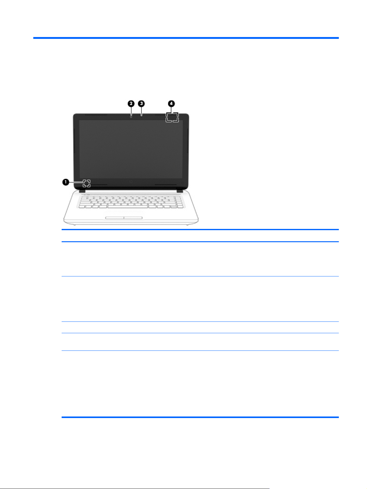
Display
Component Description
(1) Internal display switch Turns off the display and initiates Sleep if the display is closed while
the power is on.
NOTE: The internal display switch is not visible from the outside of
the computer.
(2) Webcam (select models only) Records video and captures photographs. Some models allow you to
video conference and chat online using streaming video.
To use the webcam:
▲
From the Start screen, type camera, and then select Camera
from the list of applications.
(3) Internal microphone Record sound.
(4) WLAN antenna* Send and receive wireless signals to communicate with wireless local
*The antennas are not visible from the outside of the computer. For optimal transmission, keep the areas immediately around the
antennas free from obstructions. For wireless regulatory notices, see the section of the Regulatory, Safety, and Environmental Notices
that applies to your country or region.
To access this document:
From the Start screen, type support, and then select the HP Support Assistant app.
‒ or –
From the Windows desktop, click the question mark icon in the notification area, at the far right of the taskbar.
area networks (WLANs).
Display 3
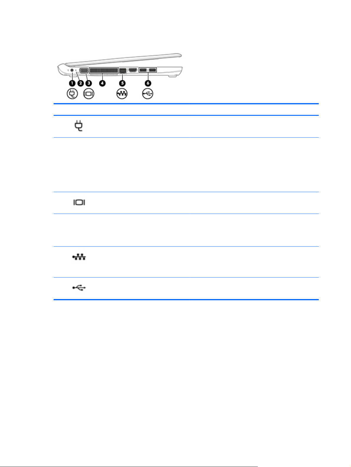
Left side
Component Description
(1)
(2) AC adapter/battery light
(3)
(4) Vent Enable airflow to cool internal components.
(5)
(6)
Power connector Connects an AC adapter.
●
Amber: The computer is connected to external power and
the battery is charged from 0 to 99 percent.
●
Blinking amber: A battery that is the only available power
source has reached a low battery level. When the battery
reaches a critical battery level, the battery light begins
blinking rapidly.
●
White: The battery is fully charged.
External monitor port Connects an external VGA monitor or projector.
NOTE: The computer fan starts up automatically to cool
internal components and prevent overheating. It is normal for
the internal fan to cycle on and off during routine operation.
RJ-45 (network) jack/status lights Connects a network cable.
●
White: The network is connected.
●
Amber: Activity is occurring on the network.
USB 3.0 ports (2) Connects an optional USB device, such as a keyboard, mouse,
external drive, printer, scanner or USB hub.
4 Chapter 2 External component identification
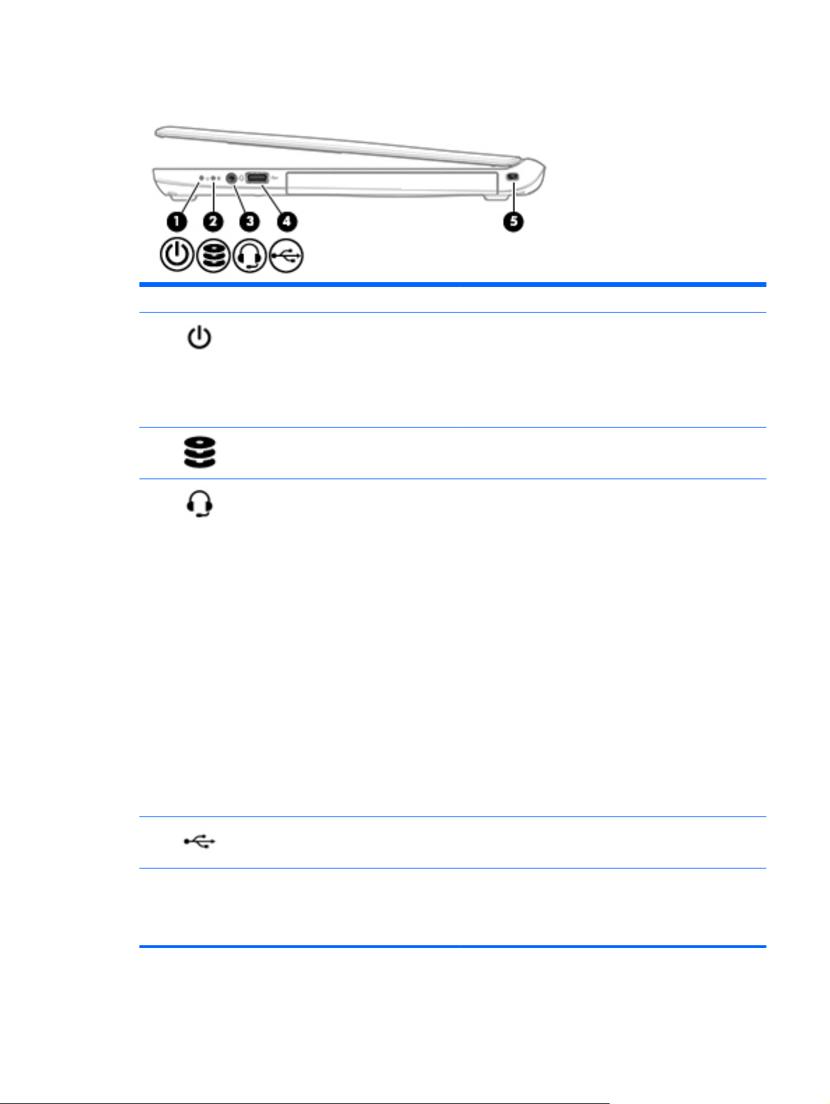
Right side
Component Description
(1)
(2)
(3)
Power light
Hard drive light
Audio-out (headphone)/Audio-in (microphone)
jack
●
White: The computer is on.
●
Blinking: The computer is in the Sleep state, a powersaving state. The computer shuts off power to the display
and other components.
●
Off: The computer is off or in Hibernation. Hibernation is a
power-saving state that uses the least amount of power.
●
Blinking white: The hard drive is being accessed.
Connects optional powered stereo speakers, headphones,
earbuds, a headset, or a television audio cable. Also connects an
optional headset microphone. This jack does not support
optional microphone-only devices.
WARNING! To reduce the risk of personal injury, adjust the
volume before putting on headphones, earbuds, or a headset.
For additional safety information, refer to the Regulatory,
Safety, and Environmental Notices.
To access this document:
▲
From the Start screen, type support, and then select the
HP Support Assistant app.
‒ or –
From the Windows desktop, click the question mark icon in
the notification area, at the far right of the taskbar.
NOTE: When a device is connected to the jack, the computer
speakers are disabled.
NOTE: Be sure that the device cable has a 4-conductor
connector that supports both audio-out (headphone) and audioin (microphone).
(4)
(5) Security cable slot Attaches an optional security cable to the computer.
USB 2.0 port Connects an optional USB device, such as a keyboard, mouse,
external drive, printer, scanner or USB hub.
NOTE: The security cable is designed to act as a deterrent, but
it may not prevent the computer from being mishandled or
stolen.
Right side 5
Top
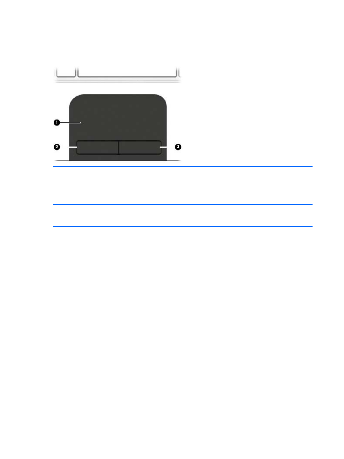
TouchPad
Component Description
(1) TouchPad zone Reads your finger gestures to move the pointer or activate
items on the screen.
NOTE: The TouchPad also supports edge-swipe gestures.
(2) Left TouchPad button Functions like the left button on an external mouse.
(3) Right TouchPad button Functions like the right button on an external mouse.
6 Chapter 2 External component identification
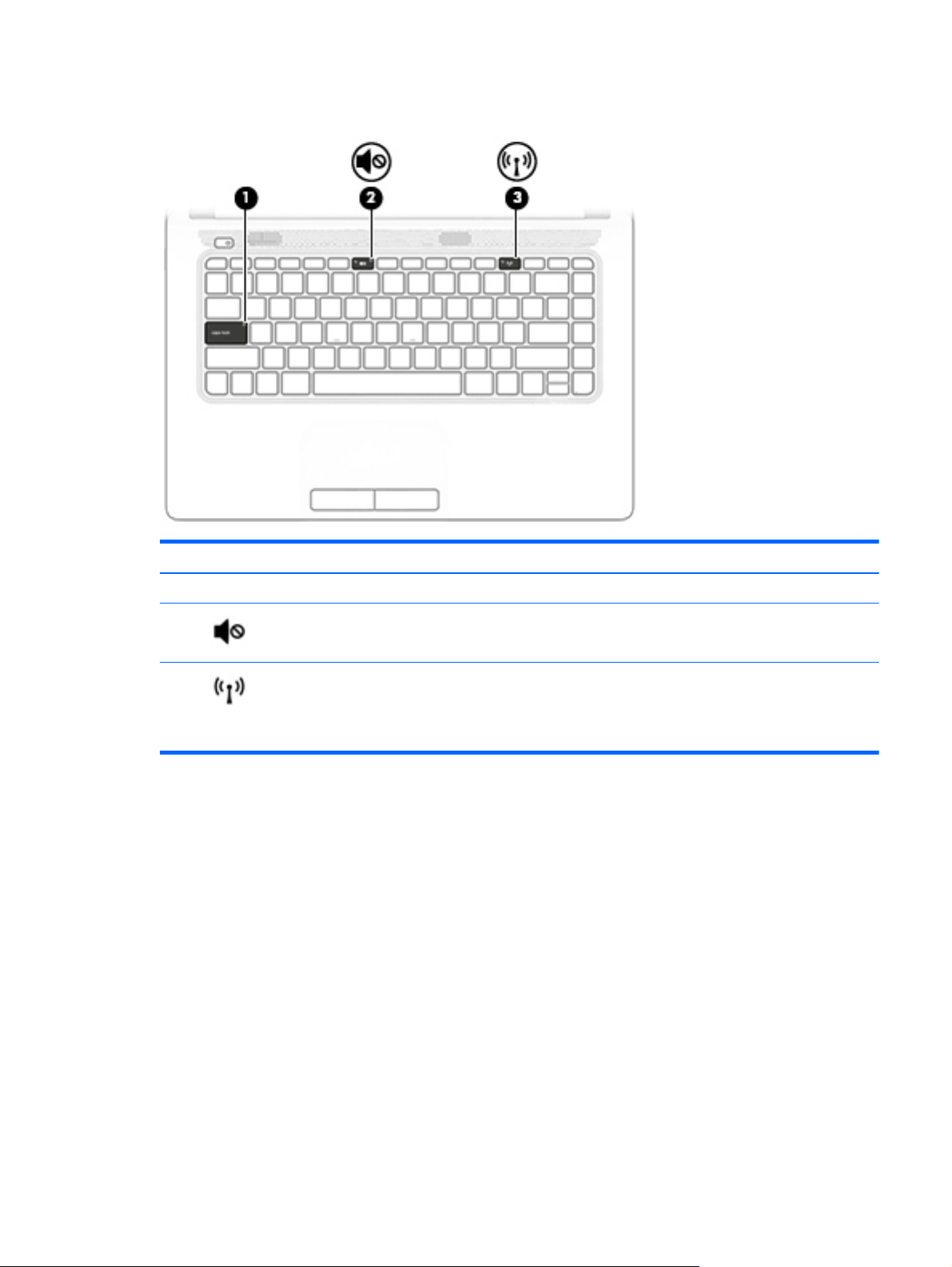
Lights
Component Description
(1) Caps lock light On: Caps lock is on, which switches the keys to all capital letters.
(2)
(3)
Mute light
Wireless light On: An integrated wireless device, such as a wireless local area
●
Amber: Computer sound is off.
●
Off: Computer sound is on.
network (WLAN) device is on.
NOTE: On some models, the wireless light is amber when all
wireless devices are off.
Top 7
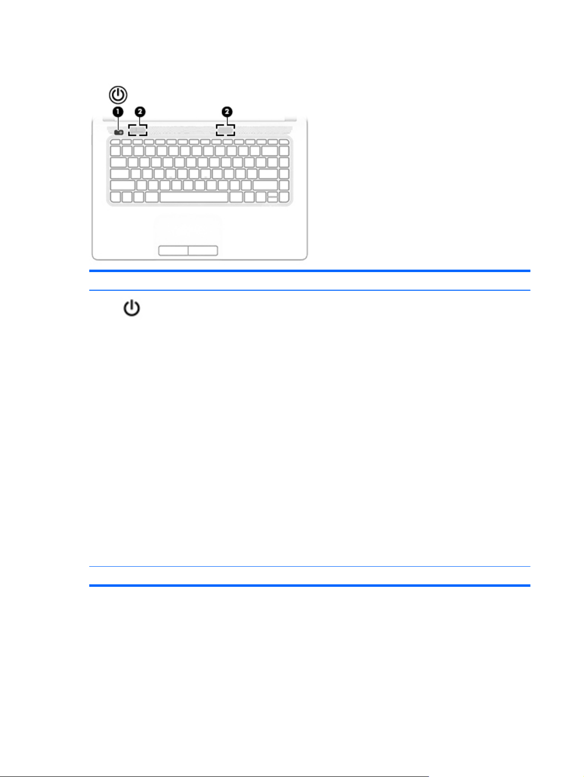
Buttons and speakers
Component Description
(1)
(2) Speakers (2) Produce sound.
Power button
●
When the computer is off, press the button to turn on the
computer.
●
When the computer is on, press the button briefly to
initiate Sleep.
●
When the computer is in the Sleep state, press the button
briefly to exit Sleep.
●
When the computer is in Hibernation, press the button
briefly to exit Hibernation.
CAUTION: Pressing and holding down the power button will
result in the loss of unsaved information.
If the computer has stopped responding and Windows shutdown
procedures are ineffective, press and hold the power button
down for at least 5 seconds to turn off the computer.
To learn more about your power settings, see your power
options.
▲
From the Start screen, type power, select Power and
sleep settings, and then select Power and sleep from the
list of applications.
‒ or –
From the Windows desktop, right-click the Start button,
and then select Power Options.
8 Chapter 2 External component identification
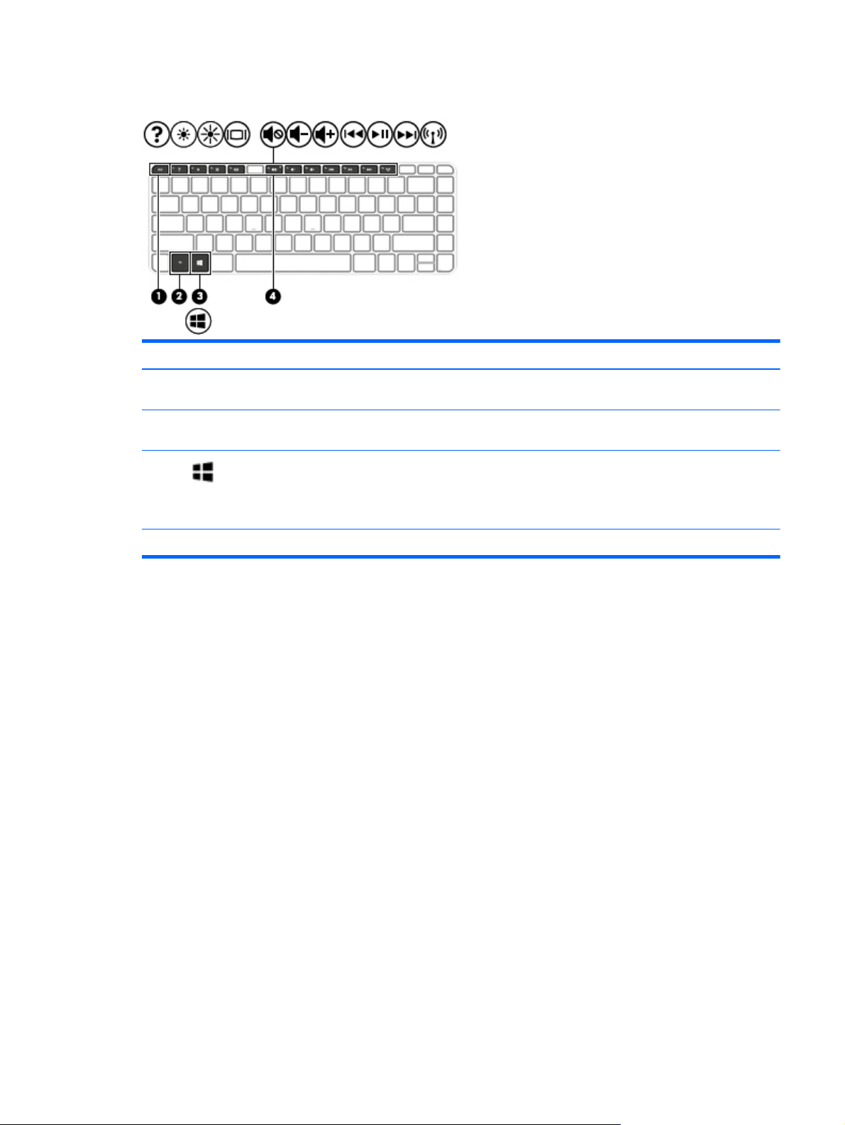
Keys
Component Description
(1) esc key Displays system information when pressed in combination with
(2) fn key Executes frequently used system functions when pressed in
(3)
(4) Action keys Execute frequently used system functions.
Windows key Returns you to the Start screen from an open app or the
the fn key.
combination with the esc key or the spacebar.
Windows desktop.
NOTE: Pressing the Windows key again will return you to the
previous screen.
Top 9
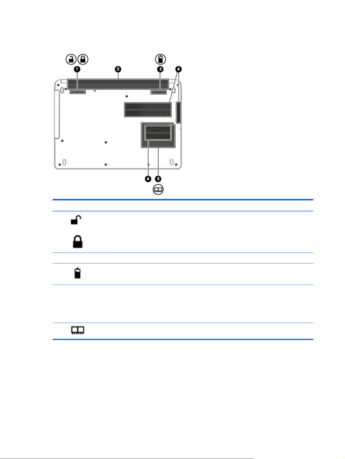
Bottom
Component Description
(1)
(2) Battery bay Holds the battery.
(3)
(4) Vents (3) Enable airflow to cool internal components.
(5)
Battery lock latch Locks and unlocks the battery in the battery bay
Battery release latch Releases the battery.
NOTE: The computer fan starts up automatically to cool
internal components and prevent overheating. It is normal
for the internal fan to cycle on and off during routine
operation.
Service door Provides access to the memory module slots
10 Chapter 2 External component identification
Labels
The labels affixed to the computer provide information you may need when you troubleshoot system
problems or travel internationally with the computer.
IMPORTANT: Check the following locations for the labels described in this section: the bottom of the
computer, inside the battery bay, under the removable service door, or on the back of the display.
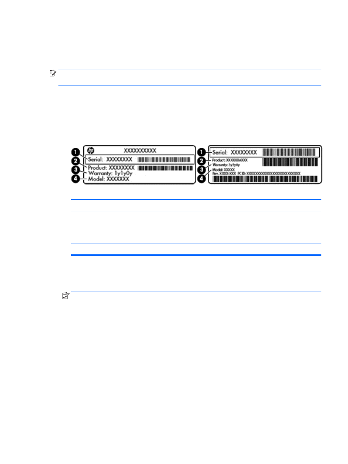
●
Service label—Provides important information to identify your computer. When contacting support,
you will probably be asked for the serial number, and possibly for the product number or the model
number. Locate these numbers before you contact support.
Your service label will resemble one of the examples shown below. Refer to the illustration that most
closely matches the service label on your computer.
Component
(1) Serial number
(2) Product number
(3) Warranty period
(4) Model number (select models only)
●
Microsoft® Certificate of Authenticity label (select models only prior to Windows 8)—Contains the
Windows Product Key. You may need the Product Key to update or troubleshoot the operating system.
HP platforms with Windows 8 or Windows 8.x preinstalled do not have the physical label. Instead a
Digital Product Key is electronically installed.
NOTE: The Digital Product Key is automatically recognized and activated by Microsoft operating
systems when a Windows 8 or Windows 8.x operating system is reinstalled using HP-approved recovery
methods.
●
Regulatory label(s)—Provide(s) regulatory information about the computer.
●
Wireless certification label(s)—Provide(s) information about optional wireless devices and the approval
markings for the countries or regions in which the devices have been approved for use.
Labels 11
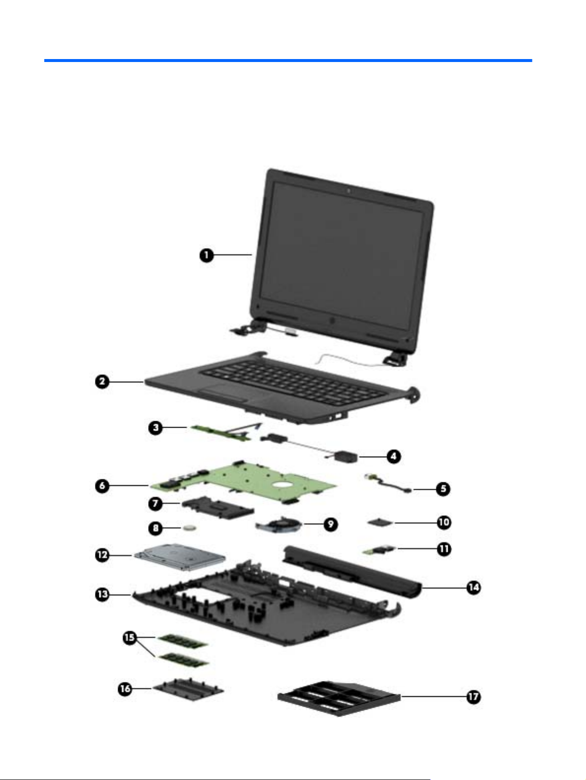
3 Illustrated parts catalog
Computer major components
12 Chapter 3 Illustrated parts catalog

Item Component Spare part number
(1) Display assembly: The display assembly is spared at the subcomponent level only. For more display assembly spare part
information, see
(2) Top cover/keyboard for use in India (includes touchpad and keyboard cable) 802473-D61
Display assembly components on page 14.
(3) TouchPad button board (includes TouchPad cable, TouchPad button board cable, and
double-sided adhesive)
(4) Speaker Kit (includes left and right speakers and cables) 802477-001
(5) Power connector cable 802488-001
(6) System board equipped with an A4-PRO 3340B 2.20-GHz processor (quad core, 25 W, 2-MB
L2 cache) and the Windows 8 Professional operating system (includes replacement
thermal material)
(7) Heat sink (includes replacement thermal material) 802480-001
(8) RTC battery 718440-001
(9) Fan (includes cable) 802479-001
(10) WLAN module:
Qualcomm Atheros AR9565 802.11b/g/n 1×1 WiFi + Bluetooth 4.0 Combo Adapter 675794-001
(11) Audio/USB board 802469-001
(12) Hard drive (does not include hard drive bracket or hard drive connector adapter):
NOTE: The hard drive bracket, rubber frame, and cable are included in the Hard Drive Hardware Kit, spare part number
802471-001. See
500-GB, 5400-rpm, SATA, 7.0-mm hard drive 778186-001
(13) Base enclosure 802470-001
Mass storage devices on page 15 for more information on the Hard Drive Hardware Kit.
802468-001
802492-601
(14) Li-ion battery
6-cell, 47-WHr, 2.20-AHr, Li-ion battery 796352-001
4-cell, 41-WHr, 2.80-AHr, Li-ion battery 752237-001
(15) Memory modules (DDR3L, 12800, 1600-MHz):
2 GB 691739-001
Plastics Kit, includes: 802476-001
(16) Memory cover
(17) Optical drive bay space saver
Computer major components 13
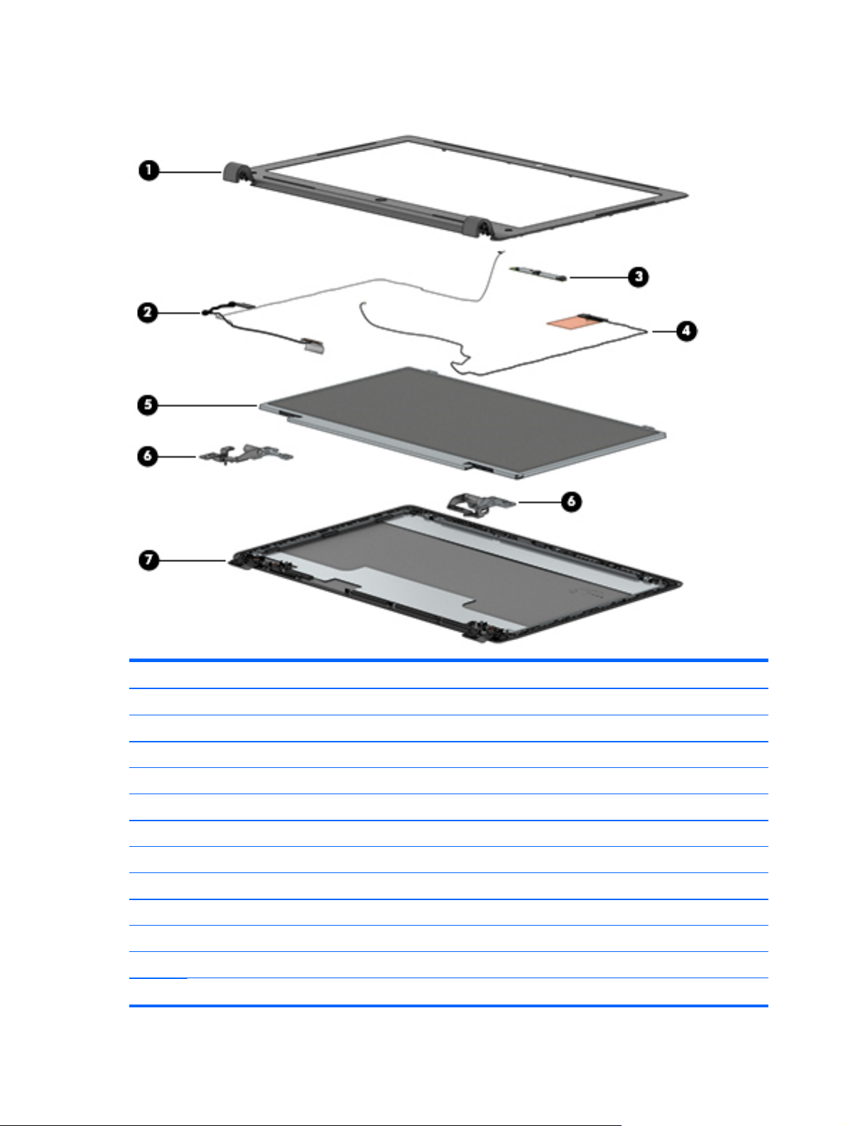
Display assembly components
Item Component Spare part number
(1) Display bezel
For use in models with a webcam 805099-001
For use in models without a webcam 805100-001
(2) Display panel cable
For use in models with a webcam 802483-001
For use in models without a webcam 805102-001
(3) Webcam/microphone module (includes double-sided adhesive) 802486-001
(4) Antenna Kit, WLAN 802484-001
(5) 35.6 cm (14.0-in), HD, SVA display panel 802491-001
Display Hinge Kit, includes: 802485-001
(6) Left and right display hinge brackets
(7) Display enclosure 802482-001
14 Chapter 3 Illustrated parts catalog
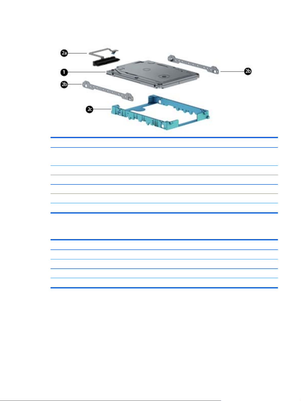
Mass storage devices
Item Component Spare part number
(1) Hard drive (does not include hard drive bracket, hard drive connector adapter, or screws):
NOTE: The hard drive bracket, hard drive connector adapter, and screws are included in the Hard Drive Hardware Kit.
500-GB, 5400-rpm, SATA, 7.0-mm hard drive 778186-001
Hard Drive Hardware Kit, includes: 802471-001
(2a) Hard drive rubber frame
(2b) Hard drive brackets (left and right)
(2c) Hard drive connector/cable
Miscellaneous parts
Component Spare part number
65-W HP Smart adapter (non-PFC, EM, 4.5-mm) 714657-001
Power cord for use only in India (3-pin, black, 1.0-m): 755530-D61
Rubber Kit 802487-001
Screw Kit 802475-001
Sequential part number listing
CSR flag designations:
A = Mandatory
B = Optional
C = Service technician recommended
N = Non-user replaceable
Mass storage devices 15

Spare part number CSR flag Description
691739-001 A 2-GB memory module (PCL3, 12800, 1600-MHz)
675794-001 N Qualcomm Atheros AR9565 802.11b/g/n 1×1 WiFi + Bluetooth 4.0 Combo Adapter
714657-001 A 65-W HP Smart adapter (non-PFC, EM, 4.5-mm)
752237-001 N 4-cell, 41-WHr, 2.80-AHr, Li-ion battery
755530-D61 A Power cord for use in India (3-pin, black, 1.0-m)
778186-001 N 500-GB, 5400-rpm, SATA, 7.0-mm hard drive (does not include hard drive bracket or hard
drive connector adapter)
NOTE: The bracket, rubber frame, and cable are included in the Hard Drive Hardware Kit,
spare part number 802471-001.
796352-001 N 6-cell, 47-WHr, 2.20-AHr, Li-ion battery
802468-001 N Touchpad button board
802469-001 N Audio/USB board
802470-001 N Base enclosure
802471-001 N Hard Drive Hardware Kit (includes bracket, rubber frame, and cable)
718440-001 N RTC battery (includes cable and double-sided adhesive)
802473-D61 N Keyboard for use in India (includes touchpad and keyboard cable)
802475-001 N Screw Kit
802476-001 N Plastics Kit (includes memory module compartment cover and optical drive bay space saver)
802477-001 N Speaker Kit (includes left and right speakers and cables)
802479-001 N Fan (includes cable)
802480-001 N Heat sink (includes replacement thermal material)
802482-001 N Display enclosure
802483-001 N Display cable for use in models with a webcam
802484-001 N Antenna Kit (includes left and right wireless antenna cables and transceivers)
802485-001 N Display Hinge Kit (includes left and right display hinges)
802486-001 N Webcam/microphone module (includes double-sided adhesive)
802487-001 N Rubber Kit (includes base enclosure rubber feet)
802488-001 N Power connector cable
802491-001 N 35.6–cm (14.0-in), HD, SVA display panel
802492-601 N System board equipped with an A4-PRO 3340B 2.20-GHz processor (quad core, 25 W, 2-MB L2
cache) and the Windows 8 Professional operating system (includes replacement
thermal material
805099-001 N Display bezel for use in models with a webcam
805100-001 N Display bezel for use in models without a webcam
805102-001 N Display cable for use in models without a webcam
16 Chapter 3 Illustrated parts catalog
 Loading...