

Page 1

HP 14 Notebook PC
Compaq 14 Notebook PC
HP 240 G3 Notebook PC
HP 245 G3 Notebook PC
HP 246 G3 Notebook PC
Maintenance and Service Guide
Page 2

© Copyright 2014 Hewlett-Packard
Development Company, L.P.
AMD and Radeon are trademarks of Advanced
Micro Devices, Inc. Bluetooth is a trademark
owned by its proprietor and used by HewlettPackard Company under license. Intel, Celeron,
Core, and Pentium are trademarks of Intel
Corporation in the U.S. and other countries.
Microsoft and Windows are U.S. registered
trademarks of the Microsoft group of
companies. SD Logo is a trademark of
its proprietor.
The information contained herein is subject to
change without notice. The only warranties for
HP products and services are set forth in the
express warranty statements accompanying
such products and services. Nothing herein
should be construed as constituting an
additional warranty. HP shall not be liable for
technical or editorial errors or omissions
contained herein.
Fourth Edition: November 2014
First Edition: March 2014
Document Part Number: 764382-004
Product notice
This guide describes features that are common
to most models. Some features may not be
available on your computer.
Not all features are available on all editions of
Windows 8. This computer may require
upgraded and/or separately purchased
hardware, drivers, and/or software to take full
advantage of Windows 8 functionality. See
http://www.microsoft.com for details.
This computer may require upgraded and/ or
separately purchased hardware and/or a DVD
drive to install the Windows 7 software and
take full advantage of Windows 7 functionality.
See http://windows.microsoft.com/en-us/
windows7/get-know-windows-7 for details.
Page 3

Safety warning notice
WARNING! To reduce the possibility of heat-related injuries or of overheating the device, do not place the
device directly on your lap or obstruct the device air vents. Use the device only on a hard, flat surface. Do not
allow another hard surface, such as an adjoining optional printer, or a soft surface, such as pillows or rugs or
clothing, to block airflow. Also, do not allow the AC adapter to contact the skin or a soft surface, such as
pillows or rugs or clothing, during operation. The device and the AC adapter comply with the user-accessible
surface temperature limits defined by the International Standard for Safety of Information Technology
Equipment (IEC 60950).
iii
Page 4

iv Safety warning notice
Page 5

Table of contents
1 Product description ....................................................................................................................................... 1
2 External component identification ................................................................................................................. 7
Display ................................................................................................................................................................... 7
Front ....................................................................................................................................................................... 8
Right side ............................................................................................................................................................... 8
Left side ................................................................................................................................................................. 9
Top ....................................................................................................................................................................... 11
TouchPad ........................................................................................................................................... 11
Lights ................................................................................................................................................. 12
Button ................................................................................................................................................ 13
Keys ................................................................................................................................................... 14
Bottom ................................................................................................................................................................. 15
Labels ................................................................................................................................................................... 16
3 Illustrated parts catalog .............................................................................................................................. 19
Computer major components ............................................................................................................................. 19
Display assembly subcomponents ..................................................................................................................... 27
Mass storage devices .......................................................................................................................................... 29
Miscellaneous parts ............................................................................................................................................. 29
Sequential part number listing ........................................................................................................................... 30
4 Removal and replacement procedures ........................................................................................................... 45
Preliminary replacement requirements .............................................................................................................. 45
Tools required ................................................................................................................................... 45
Service considerations ...................................................................................................................... 45
Plastic parts .................................................................................................................... 45
Cables and connectors .................................................................................................... 45
Drive handling ................................................................................................................. 46
Grounding guidelines ........................................................................................................................ 46
Electrostatic discharge damage ..................................................................................... 46
Packaging and transporting guidelines ....................................................... 47
Component replacement procedures ................................................................................................................. 49
Battery ............................................................................................................................................... 49
Display subcomponents (bezel, webcam, panel) ............................................................................. 50
Optical drive ...................................................................................................................................... 53
v
Page 6

Service cover ..................................................................................................................................... 55
Memory module ................................................................................................................................ 56
Keyboard ........................................................................................................................................... 57
Top cover ........................................................................................................................................... 60
Power button board .......................................................................................................................... 65
TouchPad button board .................................................................................................................... 66
USB board .......................................................................................................................................... 67
Hard drive .......................................................................................................................................... 68
WLAN module .................................................................................................................................... 71
Power connector cable ...................................................................................................................... 73
Fan ..................................................................................................................................................... 74
Display assembly .............................................................................................................................. 76
System board .................................................................................................................................... 83
Speakers ............................................................................................................................................ 89
Heat sink assembly ........................................................................................................................... 91
RTC battery ........................................................................................................................................ 94
5 Using Setup Utility (BIOS) and HP PC Hardware Diagnostics (UEFI) in Windows 8 ............................................... 97
Starting Setup Utility (BIOS) ................................................................................................................................ 97
Updating the BIOS ................................................................................................................................................ 97
Determining the BIOS version ........................................................................................................... 97
Downloading a BIOS update .............................................................................................................. 98
Using HP PC Hardware Diagnostics (UEFI) .......................................................................................................... 98
Downloading HP PC Hardware Diagnostics (UEFI) to a USB device .................................................. 99
6 Using Setup Utility (BIOS) and System Diagnostics in Windows 7 ................................................................... 101
Starting Setup Utility (BIOS) .............................................................................................................................. 101
Updating the BIOS .............................................................................................................................................. 101
Determining the BIOS version ......................................................................................................... 101
Downloading a BIOS update ........................................................................................................... 102
Using HP PC Hardware Diagnostics (UEFI) ........................................................................................................ 102
Downloading HP PC Hardware Diagnostics (UEFI) to a USB device ............................................... 103
7 Computer Setup (BIOS) and HP PC Hardware Diagnostics (UEFI) in SUSE Linux ................................................. 105
Starting Computer Setup .................................................................................................................................. 105
Using Computer Setup ....................................................................................................................................... 105
Navigating and selecting in Computer Setup ................................................................................. 105
Restoring factory settings in Computer Setup ............................................................................... 106
Updating the BIOS .............................................................................................................................................. 106
Determining the BIOS version ......................................................................................................... 106
vi
Page 7

Downloading a BIOS update ........................................................................................................... 107
Using HP PC Hardware Diagnostics (UEFI) ........................................................................................................ 107
Downloading HP PC Hardware Diagnostics (UEFI) to a USB device ............................................... 108
8 Specifications ........................................................................................................................................... 109
Computer specifications .................................................................................................................................... 109
35.6-cm (14.0-in) display specifications .......................................................................................................... 110
Hard drive specifications ................................................................................................................................... 111
DVD±RW SuperMulti DL Drive specifications .................................................................................................... 112
9 Backing up, restoring, and recovering in Windows 8 ..................................................................................... 113
Creating recovery media and backups .............................................................................................................. 113
Creating HP Recovery media ........................................................................................................... 113
Restore and recovery ........................................................................................................................................ 114
Recovering using HP Recovery Manager ........................................................................................ 115
What you need to know ................................................................................................ 115
Using the HP Recovery partition (select models only) ................................................ 115
Using HP Recovery media to recover ........................................................................... 116
Changing the computer boot order .............................................................................. 116
Removing the HP Recovery partition ............................................................................................. 116
10 Backing up, restoring, and recovering in Windows 7 ................................................................................... 117
Creating backups ............................................................................................................................................... 117
Creating recovery media to recover the original system ............................................................... 117
What you need to know ................................................................................................ 117
Creating the recovery media ...................................................................... 118
Creating system restore points ...................................................................................................... 118
What you need to know ................................................................................................ 118
Creating a system restore point ................................................................................... 118
Backing up system and personal information ............................................................................... 118
Tips for a successful backup ........................................................................................ 119
What you need to know ................................................................................................ 119
Creating a backup using Windows Backup and Restore .............................................. 119
Restore and recovery ........................................................................................................................................ 120
Restoring to a previous system restore point ................................................................................ 120
Restoring specific files .................................................................................................................... 120
Restoring specific files using Windows Backup and Restore ...................................... 120
Recovering the original system using HP Recovery Manager ........................................................ 120
What you need to know ................................................................................................ 120
Recovering using HP Recovery partition (select models only) .................................... 121
vii
Page 8

Recovering using the recovery media .......................................................................... 121
Changing the computer boot order ........................................................... 121
11 Backup and Recovery in SUSE Linux ........................................................................................................... 123
Backing up your information ............................................................................................................................. 123
Performing a system recovery .......................................................................................................................... 123
12 Statement of Volatility ............................................................................................................................ 125
Non-volatile memory usage ............................................................................................................................. 127
Questions and answers ..................................................................................................................................... 129
13 Power cord set requirements .................................................................................................................... 131
Requirements for all countries ......................................................................................................................... 131
Requirements for specific countries and regions ............................................................................................. 132
14 Recycling ................................................................................................................................................ 135
Index ........................................................................................................................................................... 137
viii
Page 9

1 Product description
Category Description HP/
Product name HP 14 Notebook PC √√
Compaq 14 Notebook PC √√
HP 240 G3 Notebook PC √
HP 245 G3 Notebook PC √
HP 246 G3 Notebook PC √
Processors Intel 5th generation processors:
Intel Core i5-5200U (2.2 GHz, SC turbo up to 2.7 GHz, 3-MB L3 Cache,
1600MHz)
Intel Core i3-5010U (2.1 GHz, 3-MB L3 Cache, 1600MHz)
Intel Core i3-5005U (2.0 GHz, 3-MB L3 Cache, 1600MHz)
Intel 4th generation processors:
Intel Core i3-4030U (1.9GHz, 3-MB L3 Cache, 1600MHz)
Intel Core i5-4210U (1.7-GHz, 3-MB L3 cache, 1600-MHz)
Intel Core i3-4010U (1.7-GHz, 3-MB L3 cache, 1600-MHz)
Intel Core i3-4005U (1.7-GHz, 3-MB L3 Cache, 1600MHz)
Intel Core i3-3217U (1.8GHz, 3-MB L3 Cache, 1600MHz)
Intel Bay Trail M processors:
Intel Pentium® N3540 (2.16-GHz, SC turbo up to 2.66 GHz, 2-MB L2 Cache,
1333MHz)
CPQ14
(Intel)
√ √
HP/
CPQ14
(AMD)
HP
240/246
G3
HP
245
G3
Intel Pentium N3530 (2.58-GHz, 2-MB L2 Cache, 1333MHz)
Intel Pentium N3520 (2.17-GHz, 2-MB L2 Cache, 1333MHz)
Intel Celeron® N2840 (2.58-GHz, SC turbo up to 2.58 GHz, 2-MB L2 Cache,
1333MHz)
Intel Celeron N2830 (2.42-GHz, 2-MB L2 Cache, 1333MHz)
Intel Celeron N2815 (1.86-GHz, 1-MB L2 Cache, 1066MHz)
AMD processors:
A8-6410 (2.0GHz, up to 2.4GHz, 2MB L2), Quad 15W, Max DDR3L-1600
A4-6310 (1.8GHz, 2MB L2), Quad 15W, Max DDR3L-1600
A4-6210 (1.8GHz, 2MB L2), Quad 15W, Max DDR3L-1600
E2-6110 (1.5GHz, 2MB L2), Quad 15W, Max DDR3L-1600
E1-6010 (1.35GHz, 1MB L2), Dual 10W, Max DDR3L-1333
AMD A6-5200 (2.0GHz, 2MB L2, 1600MHz DDR3L), Quad 25W
√ √
1
Page 10

Category Description HP/
CPQ14
(Intel)
AMD A4-5000 (1.5GHz, 2MB L2, 1600MHz DDR3L), Quad 15W
AMD E2-3800 (1.3GHz, 2MB L2, 1600MHz DDR3L), Quad 15W
A4-5050 (Quad-core Processor 1.55GHz)
E1-2150 (Dual-core Processor 1.05GHz)
HP/
CPQ14
(AMD)
HP
240/246
G3
HP
245
G3
Chipset Intel Lynx Point-LP PCH
Intel HM76 Express Chipset
Intel Bay Trail M
Integrated SOC FCH √ √
Graphics Internal graphics:*
Intel HD Graphics 5500 (5th generation processors)
Intel HD Graphics 4400 (4th generation processors)
Intel HD Graphics (Bay Trial processors)
*HP 246 G3 models offer only external graphics.
External graphics:
Nvidia 820M N15V-GM 1 GB or 2 GB VRAM
GPU power management enabled at launch
Support DX11
Support dynamic switching
Support HD Decode and HDMI
Internal Graphics:
AMD Radeon™ HD 8400 Graphics
√ √
√ √
√ √
AMD Radeon HD 8330 Graphics
AMD Radeon HD 8210 Graphics
AMD Radeon R5 Graphics
AMD Radeon R3 Graphics
AMD Radeon R2 Graphics
Switchable Discrete Graphics:
AMD Sun LE (18W) Radeon™ HD 8570M with up to 1024MB of dedicated
video memory (support for A4-6300/ A4-5050/E1-6010)
AMD Sun LE (18W) RadeonT HD 8570M with up to 2048MB of dedicated
video memory (support for A8-6500/ A4-6300/ E1-6050/ A4-5000/
A4-5050/ E1-2100)
Panel 35.6-cm (14.0-in), high-definition (HD), WLED, SVA, BrightView
(1366×768) display, flat 3.6 mm; typical brightness: 200 nits
35.6-cm (14.0-in), HD, WLED, BrightView (1366×768) display, slim, SVA;
typical brightness: 200 nits (for eTP2 touch solution only)
Touchscreen, multitouch enabled
2 Chapter 1 Product description
√ √
√√√ √
Page 11

Category Description HP/
CPQ14
(Intel)
Supports LVDS
HP/
CPQ14
(AMD)
HP
240/246
G3
HP
245
G3
Memory 2 customer-accessible/upgradable memory module slot
Supports dual-channel memory
DDR3L-1600-MHz Single Channel Support
DDR3L-1333-MHz Single Channel Support (DDR3-1600 downgrade to
DDR3-1333)
DDR3L-1066-MHz Single Channel Support (DDR3-1600 downgrade to
DDR3-1066)
Supports up to 16 GB of system RAM in the following configurations:
●
16384-MB total system memory (8192×2)
●
12288-MB total system memory (8192+4096)
●
8192-MB total system memory (8192×1)
●
8192-MB total system memory (4096×2)
●
6144-MB total system memory (4096+2048)
●
4096-MB total system memory (4096×1)
●
4096-MB total system memory (2048×2)
●
2048-MB total system memory (2048×1)
1 customer-accessible/upgradable memory module slot
Supports single-channel memory
√ √
√ √
DDR3L-1600-MHz Single Channel Support
DDR3L-1333-MHz Single Channel Support (DDR3-1600 downgrade to
DDR3-1333)
Supports up to 8 GB of system RAM in the following configurations:
●
8192-MB total system memory (8192×1)
●
4096-MB total system memory (4096×1)
●
2048-MB total system memory (2048×1)
Hard drives Supports 6.35-cm (2.5-in) hard drives in 9.5-mm (.37-in) and 7.0-mm (.
28-in) thicknesses
Serial ATA
Supports the following hard drives:
●
1-TB, 5400-rpm, 9.5-mm
●
750-GB, 5400-rpm, 9.5-mm
●
500-GB, 7200-rpm, 7.0-mm
●
500-GB, 5400-rpm, 9.5-mm or 7.0-mm
●
320-GB, 5400-rpm, 9.5-mm or 7.0-mm
Optical drive Fixed, serial ATA, 9.5-mm tray load
DVD+/-RW Double-Layer SuperMulti
√√√ √
√√√ √
3
Page 12

Category Description HP/
CPQ14
(Intel)
Supports zero power optical drive
HP/
CPQ14
(AMD)
HP
240/246
G3
HP
245
G3
Audio/video Single digital microphone
HD audio
Dual speakers
HP TrueVision HD webcam (fixed, no tilt with activity LED, 1280×720 by
30 frames per second)
Ethernet Integrated 10/100 network interface card (NIC) √√√ √
Wireless Integrated wireless local area network (WLAN) options by way of
wireless module
One or two WLAN antennas built into display assembly
Compatible with Miracast-certified devices
Single antenna support
Support for the following WLAN formats:
●
Realtek RTL8188EE 802.11bgn 1x1 Wi-Fi Adapter
●
Qualcomm Atheros AR9485 802.11bgn 1x1 Wi-Fi Adapter
●
Ralink RT3290LE 802.11bgn 1x1 Wi-Fi + BT 4.0 Combo Adapter
●
QCA 9565 802.11bgn 1x1 Wi-Fi + BT4.0 Combo Adapter
●
Broadcom BCM43142 802.11 bgn 1x1 Wi-Fi + BT4.0 HMC Combo
Adapter
●
Realtek RT8723BE 802.11bgn 1x1 Wi-Fi + BT4.0 Combo Adapter
√√√ √
√√√ √
External
media card
Ports HDMI version 1.4 supporting 1920 ×1200 @ 60Hz
Keyboard/
pointing
devices
●
Broadcom BCM43142 802.11 bgn 1x1 Wi-Fi + BT4.0 HMC Combo
Adapter
●
Realtek RT8723BE 802.11bgn 1x1 Wi-Fi + BT4.0 Combo
Adapter_WW
HP Multi-Format Digital Media Reader
Support SD/SDHC/SDXC
Push-Pull Insertion/Removal
Hot Plug/unplug and auto detect for correct output to wide-aspect vs.
standard aspect video
RJ-45 (Ethernet, includes link and activity lights)
USB 3.0 (1 port)
USB 2.0 (2 ports)
AC Smart Pin adapter plug
Headphone/microphone in combo jack
Full-size "island style" keyboard with numeric keypad √√√ √
√√ √
√√√ √
√√√ √
4 Chapter 1 Product description
Page 13

Category Description HP/
CPQ14
(Intel)
HP/
CPQ14
(AMD)
HP
240/246
G3
HP
245
G3
TouchPad with multi-touch gestures, 2-finger scrolling, and pinch-
zoom enabled
Taps enabled by default
Support Win8.1+D212 Modern Trackpad Gestures
Support PS/2, profile sensor (reserve for SMBus)
Power
requirements
4-cell, 41-Whr Li-ion battery
Security Kensington Security Lock
AC adapters:
AC Adapter 65-W Smart nPFC, 3 pin, RC 4.5mm connector - non slim for
use in discrete models
AC Adapter 45-W Smart nPFC, 3 pin, RC 4.5mm connector - non slim for
use in UMA models
AC Adapter 65-W EM Smart nPFC, 3 pin, RC 4.5mm connector, 90 degree
plug design for use in India/China
1 meter power cord
3-cell, 31-Whr Li-ion battery
Support Intel Anti-Theft
Support Intel IPT
OTP support
√√√ √
√√√ √
√√√ √
√ √
Kensington Security Lock √ √
Operating
system
Serviceability End-user replaceable parts:
Preinstalled:
●
Windows 8.1
●
Ubuntu
●
FreeDOS 2.0
●
AC adapter
●
Battery
●
Memory
●
Optical drive
●
Keyboard
√√√ √
√√√ √
5
Page 14

6 Chapter 1 Product description
Page 15
2 External component identification
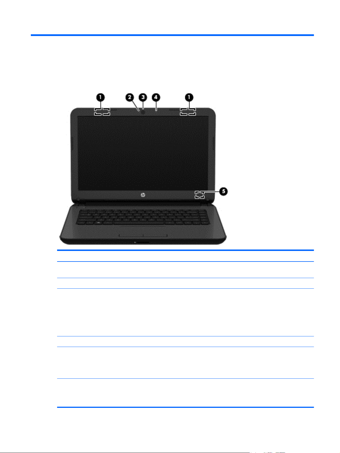
Display
Component Description
(1) WLAN antennas (1 or 2)* (select models only) Send and receive wireless signals to communicate with wireless local
area networks (WLANs).
(2) Webcam light On: The webcam is in use.
(3) Webcam Records video and captures photographs. Some models allow you to
(4) Internal microphone Records sound.
(5) Internal display switch Turns off the display and initiates Sleep if the display is closed while
*The antennas are not visible from the outside of the computer. For optimal transmission, keep the areas immediately around the
antennas free from obstructions. For wireless regulatory notices, see the section of the Regulatory, Safety, and Environmental Notices
that applies to your country or region. To access this guide in Windows 8, from the Start screen, type support, and then select the
HP Support Assistant app.
video conference and chat online using streaming video.
To use the webcam in Windows 8, from the Start screen, type
camera, and then select Camera from the list of applications.
To use the webcam in Windows 7, select Start > All Programs >
Communication and Chat > CyberLink YouCam.
the power is on.
NOTE: The internal display switch is not visible from the outside of
the computer.
Display 7
Page 16
Front
Component Description
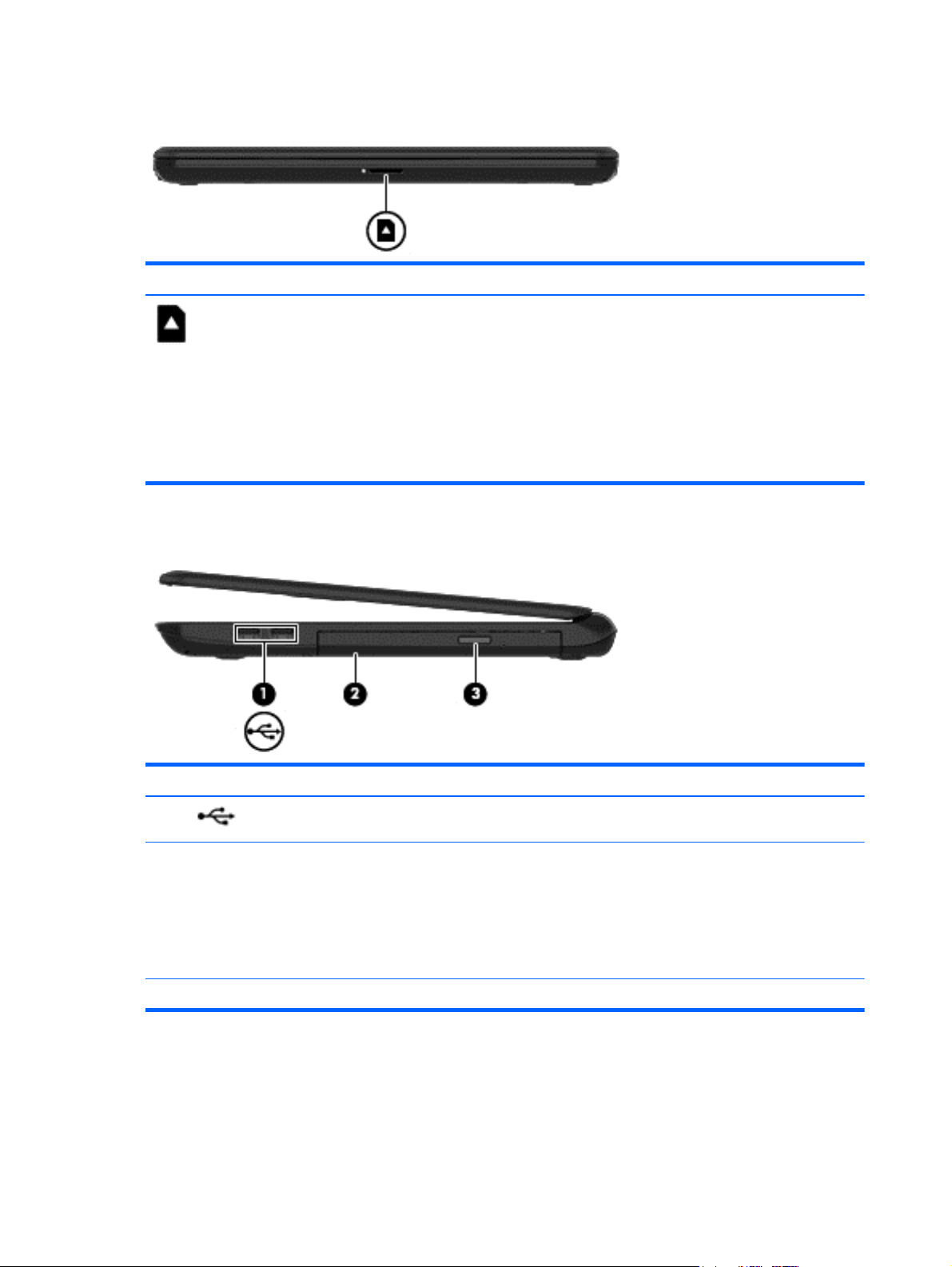
Right side
Memory card reader Reads optional memory cards that store, manage,
share, or access information.
To insert a card:
Hold the card label-side up, with connectors facing the
slot, insert the card into the slot, and then push in on the
card until it is firmly seated.
To remove a card:
Pull the card out of the slot.
Component Description
(1)
(2) Optical drive Depending on your computer model, reads an optical
(3) Optical drive eject button Releases the disc tray.
USB 2.0 ports (2) Connect an optional USB device, such as a keyboard,
8 Chapter 2 External component identification
mouse, external drive, printer, scanner or USB hub.
disc or reads and writes to an optical disc.
NOTE: For disc compatibility information, go to the
Help and Support web page. Follow the web page
instructions to select your computer model. Select
Support & Drivers, and then select Product
Information.
Page 17
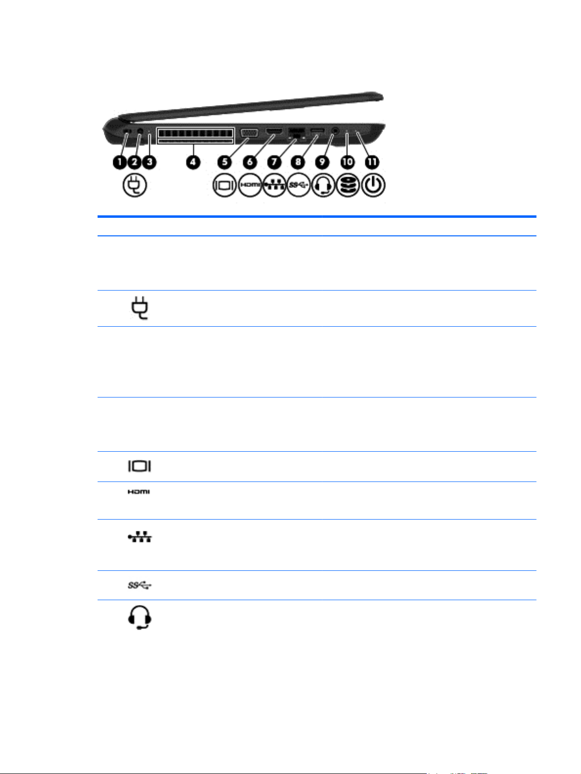
Left side
Component Description
(1) Security cable slot Attaches an optional security cable to the computer.
NOTE: The security cable is designed to act as a deterrent, but
it may not prevent the computer from being mishandled or
stolen.
(2)
(3) AC adapter light
(4) Vent Enables airflow to cool internal components.
(5)
(6)
(7)
(8)
Power connector Connects an AC adapter.
●
White: The AC adapter is connected and the battery is
charged.
●
Amber: The AC adapter is connected and the battery is
charging.
●
Off: The computer is using battery power.
NOTE: The computer fan starts up automatically to cool
internal components and prevent overheating. It is normal for
the internal fan to cycle on and off during routine operation.
External monitor port (select models only) Connects an external VGA monitor or projector.
HDMI port Connects an optional video or audio device, such as a high-
definition television, any compatible digital or audio
component, or a high-speed HDMI device.
RJ-45 (network) jack/status lights Connects a network cable.
●
White: The network is connected.
●
Amber: Activity is occurring on the network.
USB 3.0 port Connects an optional USB device, such as a keyboard, mouse,
external drive, printer, scanner or USB hub.
(9)
Audio-out (headphone)/Audio-in (microphone)
jack
Connects optional powered stereo speakers, headphones,
earbuds, a headset, or a television audio cable. Also connects an
optional headset microphone. This jack does not support
optional microphone-only devices.
Left side 9
Page 18
Component Description
WARNING! To reduce the risk of personal injury, adjust the
volume before putting on headphones, earbuds, or a headset.
For additional safety information, refer to the Regulatory,
Safety, and Environmental Notices. To access this guide in
Windows 8, from the Start screen, type support, and then
select the HP Support Assistant app.
NOTE: When a device is connected to the jack, the computer
speakers are disabled.
NOTE: Be sure that the device cable has a 4-conductor
connector that supports both audio-out (headphone) and audioin (microphone).
(10)
(11)
Hard drive light Blinking white: The hard drive is being accessed.
Power light
●
On: The computer is on.
●
Blinking: The computer is in the Sleep state, a powersaving state. The computer shuts off power to the display
and other unneeded components.
●
Off: The computer is off or in Hibernation. Hibernation is a
power-saving state that uses the least amount of power.
NOTE: For select models, the Intel® Rapid Start Technology
feature is enabled at the factory. Rapid Start Technology allows
your computer to resume quickly from inactivity.
10 Chapter 2 External component identification
Page 19
Top
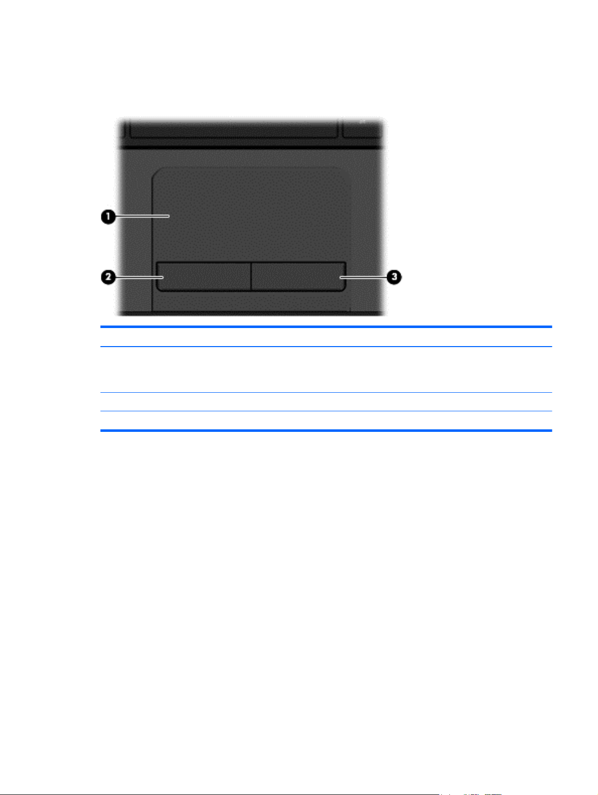
TouchPad
Component Description
(1) TouchPad zone Moves the on-screen pointer and selects or activates items on
(2) Left TouchPad button Functions like the left button on an external mouse.
(3) Right TouchPad button Functions like the right button on an external mouse.
the screen.
NOTE: The TouchPad also supports edge-swipe gestures.
Top 11
Page 20
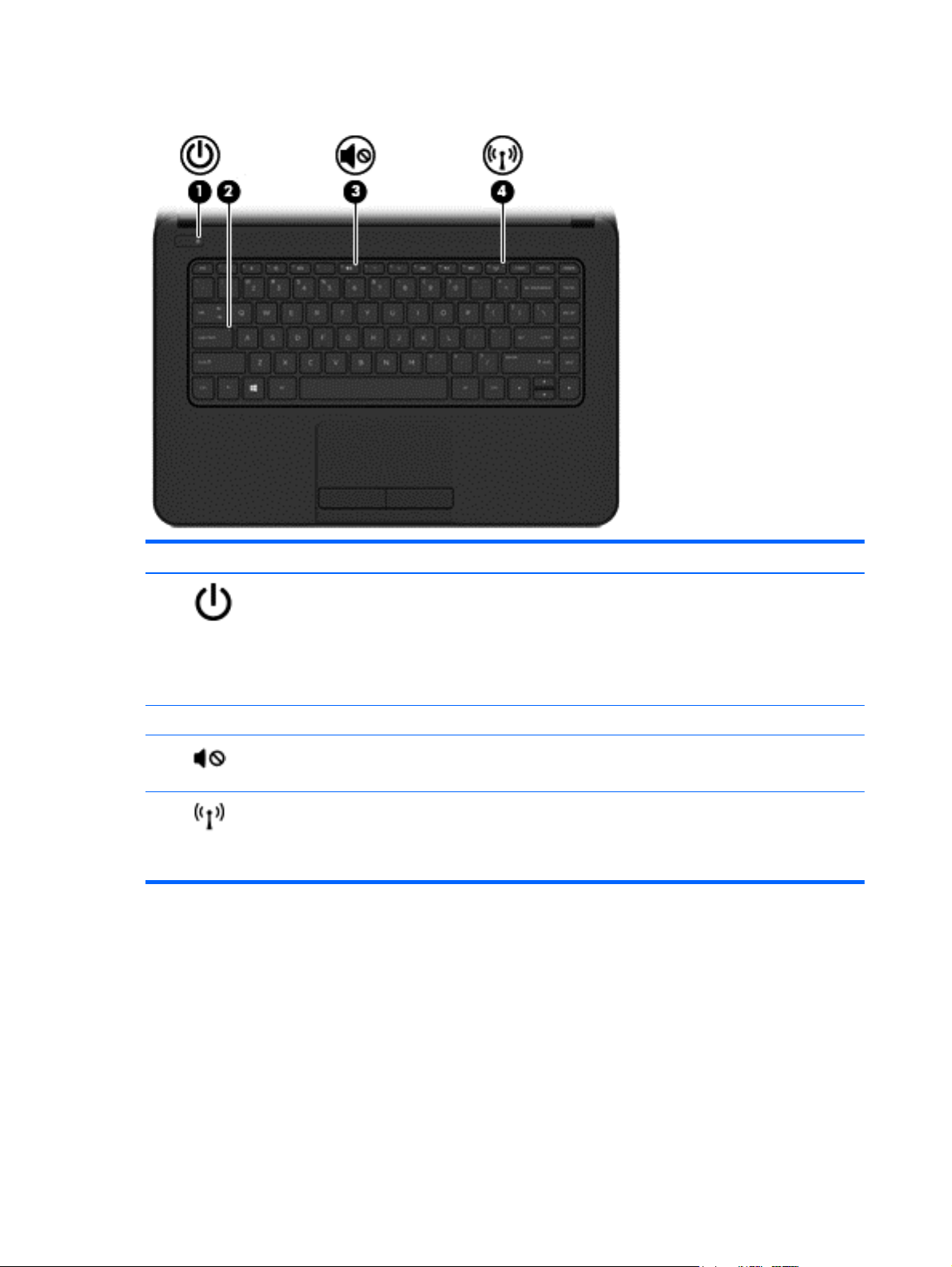
Lights
Component Description
(1)
(2) Caps lock light On: Caps lock is on, which switches the keys to all capital letters.
(3)
(4)
Power light
Mute light
Wireless light On: An integrated wireless device, such as a wireless local area
●
On: The computer is on.
●
Blinking: The computer is in the Sleep state, a powersaving state. The computer shuts off power to the display
and other unneeded components.
●
Off: The computer is off or in Hibernation. Hibernation is a
power-saving state that uses the least amount of power.
●
Amber: Computer sound is off.
●
Off: Computer sound is on.
network (WLAN) device and/or a Bluetooth® device, is on.
NOTE: On some models, the wireless light is amber when all
wireless devices are off.
12 Chapter 2 External component identification
Page 21
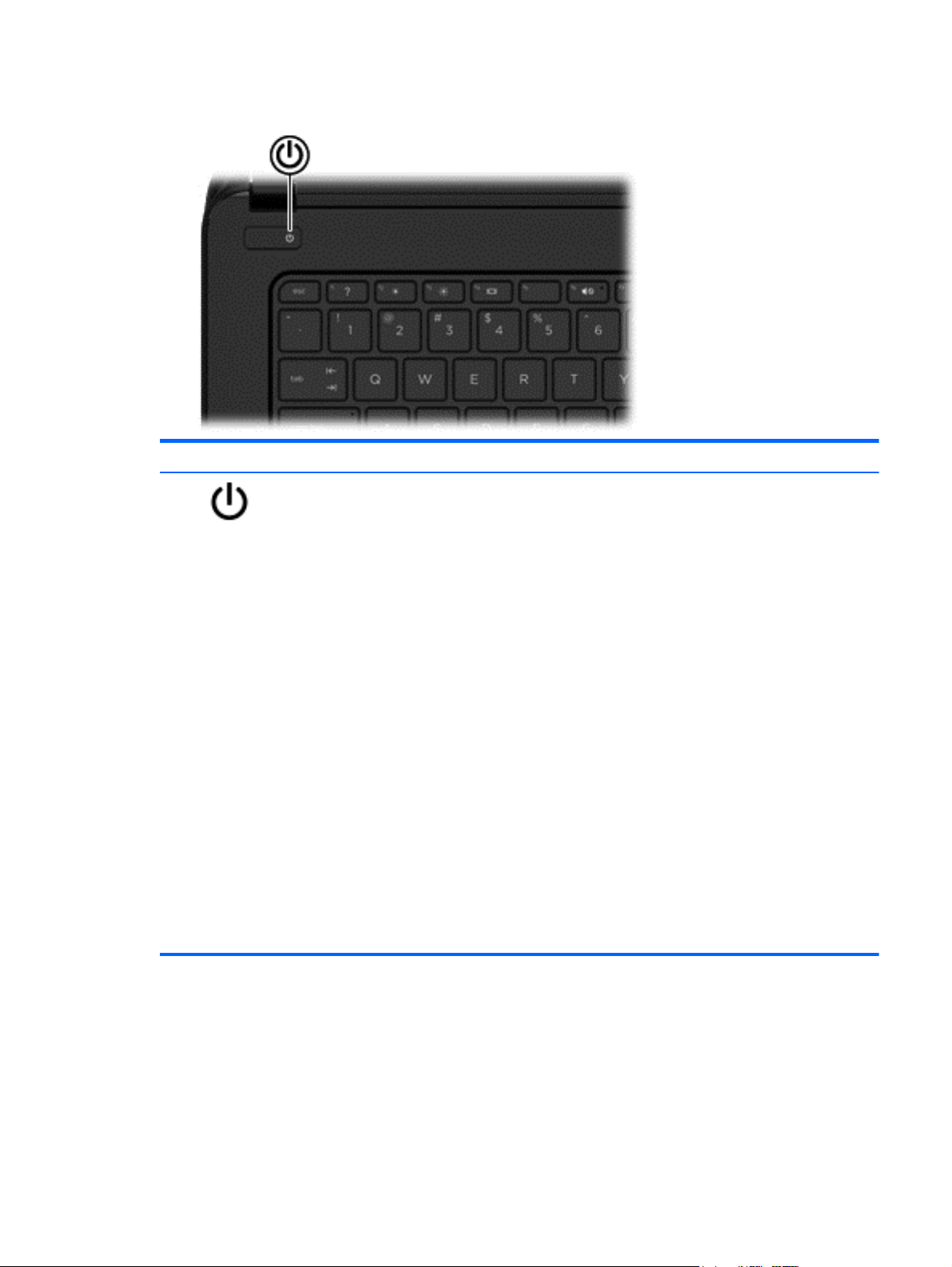
Button
Component Description
Power button
●
When the computer is off, press the button to turn on the
computer.
●
When the computer is on, press the button briefly to
initiate Sleep.
●
When the computer is in the Sleep state, press the button
briefly to exit Sleep.
●
When the computer is in Hibernation, press the button
briefly to exit Hibernation.
CAUTION: Pressing and holding down the power button will
result in the loss of unsaved information.
If the computer has stopped responding and Windows®
shutdown procedures are ineffective, press and hold the power
button down for at least 5 seconds to turn off the computer.
NOTE: For select models, the Intel® Rapid Start Technology
feature is enabled at the factory. Rapid Start Technology allows
your computer to resume quickly from inactivity.
To learn more about your power settings, see your power
options.
In Windows 8, from the Start screen, type power, select Power
and sleep settings, and then select Power and sleep from the
list of applications.
In Windows 7, select Start > Control Panel > System and
Security > Power Options,
Top 13
Page 22
Keys
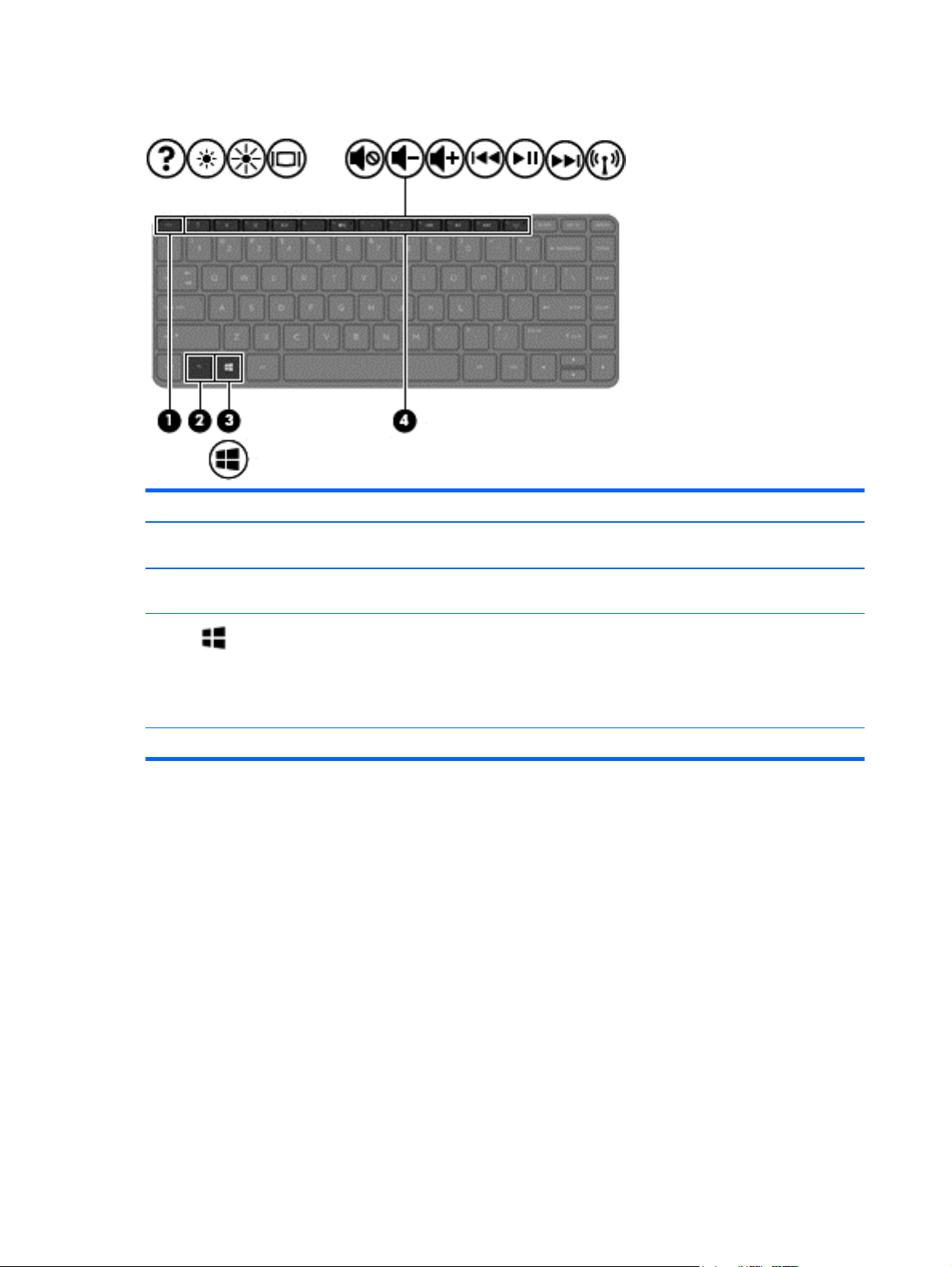
Component Description
(1) esc key Displays system information when pressed in combination with
the fn key.
(2) fn key Executes frequently used system functions when pressed in
combination with the spacebar or the esc key.
(3)
(4) Action keys Execute frequently used system functions.
Windows key Windows 8: Returns you to the Start screen from an open app or
the Windows desktop.
NOTE: Pressing the Windows key again will return you to the
previous screen.
Windows 7: Displays the Windows Start menu.
14 Chapter 2 External component identification
Page 23
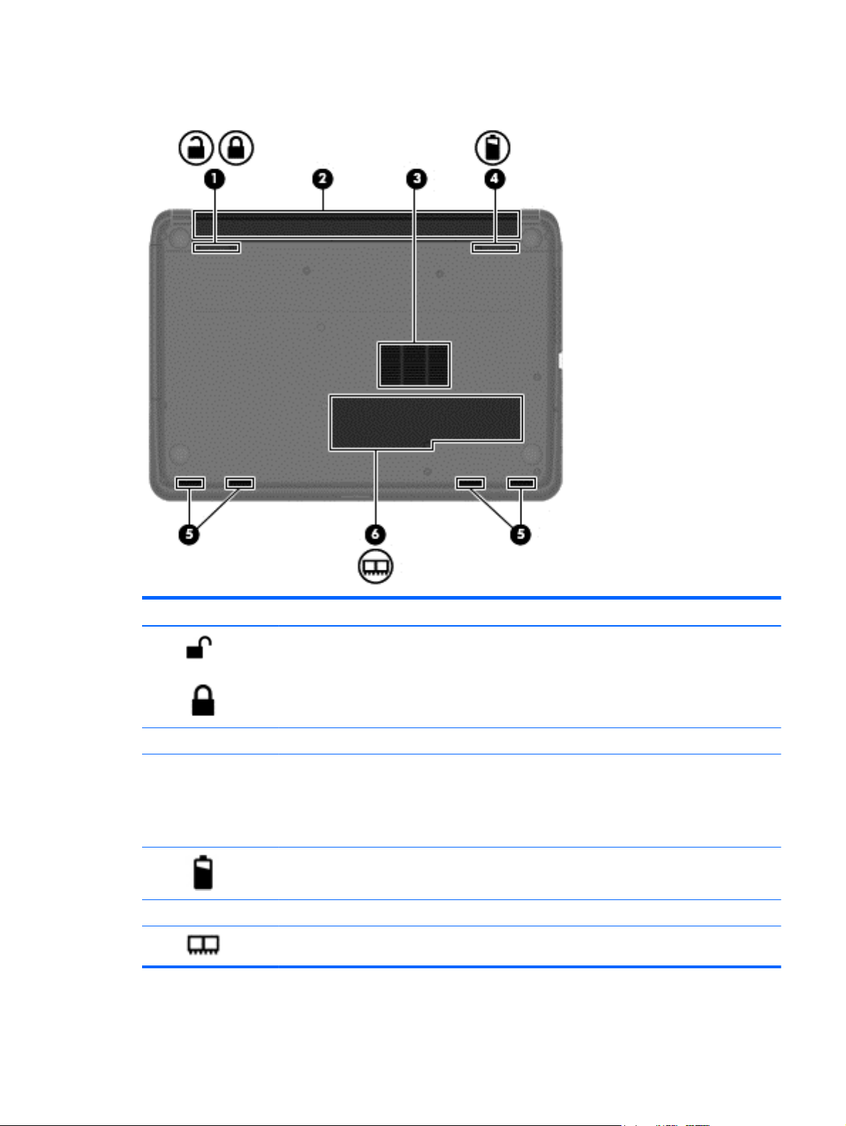
Bottom
Component Description
(1)
(2) Battery bay Holds the battery.
(3) Vent Enable airflow to cool internal components.
(4)
(5) Speaker openings (4) Produce sound.
(6)
Battery lock and unlock latch Locks and unlocks the battery in the battery bay.
NOTE: The computer fan starts up automatically to cool
internal components and prevent overheating. It is normal
for the internal fan to cycle on and off during routine
operation.
Battery release latch Releases the battery.
Service cover (select models only) Provides access to the memory module slots.
Bottom 15
Page 24
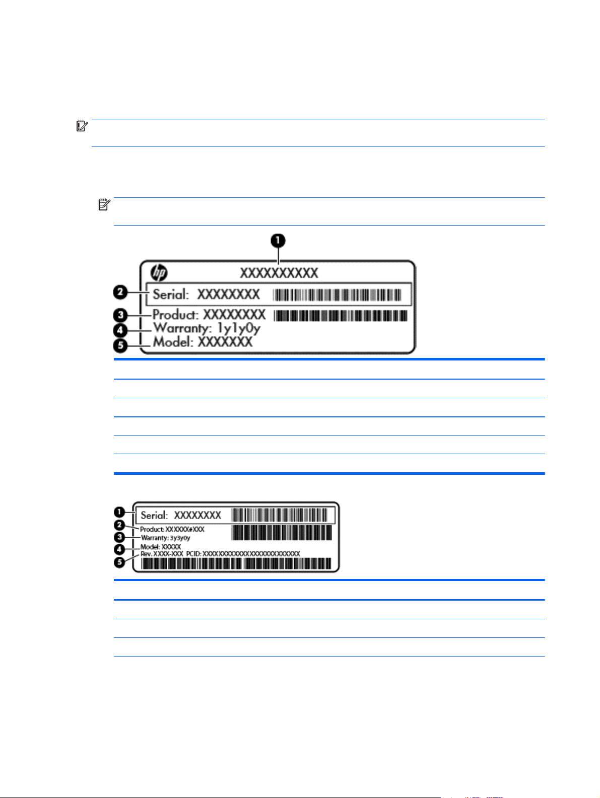
Labels
The labels affixed to the computer provide information you may need when you troubleshoot system
problems or travel internationally with the computer.
IMPORTANT: All labels described in this section will be located in one of 2 places depending on your
computer model: Affixed to the bottom of the computer, or located in the battery bay.
●
Service label—Provides important information to identify your computer. When contacting support,
you will probably be asked for the serial number, and possibly for the product number or the model
number. Locate these numbers before you contact support.
NOTE: Your service labels will resemble one of the examples shown below. Refer to the illustration
that most closely matches the service label on your computer.
Component
(1) Product name
(2) Serial number
(3) Product number
(4) Warranty period
(5) Model number (select models only)
Component
(1) Serial number
(2) Product number
(3) Warranty period
16 Chapter 2 External component identification
Page 25

Component
(4) Model number (select models only)
(5) Revision number
●
Regulatory label(s)—Provide(s) regulatory information about the computer.
●
Wireless certification label(s)—Provide(s) information about optional wireless devices and the approval
markings for the countries or regions in which the devices have been approved for use.
Labels 17
Page 26

18 Chapter 2 External component identification
Page 27
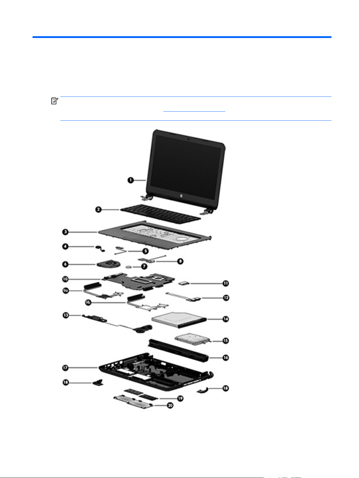
3 Illustrated parts catalog
Computer major components
NOTE: HP continually improves and changes product parts. For complete and current information on
supported parts for your computer, go to
follow the on-screen instructions.
http://partsurfer.hp.com, select your country or region, and then
Computer major components 19
Page 28

Item Component Spare part number
(1) Display assembly (35.6-cm [14.0-in] HD, anti-glare, WLED)
NOTE: For display assembly spare part information, see
(2) Keyboard
For use in the United States 757922-001
For use in the United Kingdom 757922-031
For use in France 757922-051
For use in Spain 757922-071
For use in Portugal 757922-131
For use in Turkey 757922-141
For use in Latin America 757922-161
For use in Saudi Arabia 757922-171
For use in Brazil 757922-201
For use in Russia 757922-251
For use in Thailand 757922-281
For use in Japan 757922-291
Display assembly subcomponents on page 27.
For use in Taiwan 757922-AB1
For use in South Korea 757922-AD1
For use in the Netherlands 757922-B31
For use in Israel 757922-BB1
For use in Switzerland 757922-BG1
For use in French Canada 757922-DB1
For use in Denmark, Finland, and Norway 757922-DH1
For use in the Czech Republic and Slovakia 757922-FL1
(3) Top cover (includes touchpad)
For use in HP 14 and Compaq 14 models:
●
Black 757613-001
●
Gray 758618-001
●
White 758911-001
●
Red 758912-001
●
Blue 758913-001
●
Silver 760247-001
For use in HP 245 G3 models:
For use in HP 240/246 G3 models:
●
Top cover 758618-001
20 Chapter 3 Illustrated parts catalog
Page 29

Item Component Spare part number
(4) Power connector cable 760104-001
(5) Touchpad button board (includes cables) 757609-001
(6) Fan 753894-001
(7) RTC battery 759981-001
(8) Power button board (includes cable) 757607-001
(9a) For use in models with Intel processors and discrete graphics 757602-001
For use in models with an Intel Core i3-3217U processor and discrete graphics 766502-001
For use in models with AMD processors and discrete graphics 766567-001
(9b) For use in models with Intel processors and UMA graphics 757603-001
For use in models with Intel Pentium and Celeron processors and UMA graphics 766504-001
For use in models with an Intel Core i3-3217U processor and UMA graphics 766503-001
For use in models with AMD processors and UMA graphics 766568-001
(10) System board (includes replacement thermal materials):
●
Top cover 773067-001
All Intel system boards use the following part numbers:
xxxxxx-001: Without the Windows operating system
xxxxxx-501: Windows 8.1 Standard
xxxxxx-601: Windows 8.1 Professional
HP 14, Compaq 14, and HP 240/246 G3 models with Intel processors:
NOTE: HP 246 G3 models offer only discrete graphics.
Non-touch screen models with an Intel Core i5-5200U processor and 2 GB of discrete graphics 762240-xxx
Non-touch screen models with an Intel Core i3-5010U processor and 2 GB of discrete graphics 801857-xxx
Non-touch screen models with an Intel Core i3-5010U processor and UMA graphics 801855-xxx
Non-touch screen models with an Intel Core i3-5005U processor and 2 GB of discrete graphics 791095-xxx
Non-touch screen models with an Intel Core i3-5005U processor and 1 GB of discrete graphics 791094-xxx
Non-touch screen models with an Intel Core i3-5005U processor and UMA graphics 791093-xxx
Non-touch screen models with an Intel Core i5-4210U processor and UMA graphics 755835-xxx
Non-touch screen models with an Intel Core i3-4030U processor and 2 GB of discrete graphics 779080-xxx
Non-touch screen models with an Intel Core i3-4030U processor and 1 GB of discrete graphics 779079-xxx
Non-touch screen models with an Intel Core i3-4030U processor and UMA graphics 779078-xxx
Non-touch screen models with an Intel Core i3-4010U processor and 1 GB of discrete graphics 778116-xxx
Non-touch screen models with an Intel Core i3-4010U processor and UMA graphics 755831-xxx
Non-touch screen models with an Intel Core i3-4005U processor and 2 GB of discrete graphics 755832-xxx
Non-touch screen models with an Intel Core i3-4005U processor and UMA graphics 765364-xxx
Computer major components 21
Page 30

Item Component Spare part number
Non-touch screen models with an Intel Pentium N3540 processor and UMA graphics 788003-xxx
Touch screen models with an Intel Pentium N3540 processor and UMA graphics 788208-xxx
Non-touch screen models with an Intel Celeron N2920 processor and UMA graphics 790213-xxx
Non-touch screen models with an Intel Celeron N2840 processor and UMA graphics 788004-xxx
Non-touch screen models with an Intel Celeron N2820 processor and UMA graphics 790212-xxx
Non-touch screen models with an Intel Celeron N2805 processor and UMA graphics 790211-xxx
HP 14 and Compaq 14 models with Intel processors:
Non-touch screen models with an Intel Core i5-5200U processor and 1 GB of discrete graphics 791096-xxx
Non-touch screen models with an Intel Core i5-5200U processor and UMA graphics 776890-xxx
Non-touch screen models with an Intel Core i3-5010U processor and 1 GB of discrete graphics 801856-xxx
Non-touch screen models with an Intel Core i5-4210U processor and 2 GB of discrete graphics 755834-xxx
Touch screen models with an Intel Core i5-4210U processor and 2 GB of discrete graphics 757610-xxx
Non-touch screen models with an Intel Core i5-4210U processor and 1 GB of discrete graphics 788210-xxx
Touch screen models with an Intel Core i5-4030U processor and 2 GB of discrete graphics 784981-xxx
Touch screen models with an Intel Core i3-4010U processor and 2 GB of discrete graphics 758614-xxx
Non-touch screen models with an Intel Core i3-4010U processor and 2 GB of discrete graphics 755833-xxx
Touch screen models with an Intel Core i3-4010U processor and 1 GB of discrete graphics 758613-xxx
Touch screen models with an Intel Core i3-4005U processor and UMA graphics 773153-xxx
Non-touch screen models with an Intel Core i3-4005U processor and 1 GB of discrete graphics 773154-xxx
Touch screen models with an Intel Core i3-4005U processor and 2 GB of discrete graphics 755836-xxx
Non-touch screen models with an Intel Core i3-3217U processor and UMA graphics 755829-xxx
Non-touch screen models with an Intel Core i3-3217U processor and 1 GB of discrete graphics 755830-xxx
Touch screen models with an Intel Core i3-3217U processor and UMA graphics 762239-xxx
Touch screen models with an Intel Pentium N3530 processor and UMA graphics 764051-xxx
Non-touch screen models with an Intel Pentium N3520 processor and UMA graphics 755837-xxx
Non-touch screen models with an Intel Celeron N2830 processor and UMA graphics 764050-xxx
Non-touch screen models with an Intel Celeron N2815 processor and UMA graphics 755838-xxx
HP 240/246 G3 models:
NOTE: HP 246 G3 models offer only discrete graphics.
Non-touch screen models with an Intel Pentium N3530 processor and UMA graphics 775631-xxx
Non-touch screen, GLAN models with an Intel Core i5-4210U processor and UMA graphics 795135-xxx
Non-touch screen, GLAN models with an Intel Core i3-4030 processor and UMA graphics 795136-xxx
Non-touch screen, GLAN models with an Intel Core i5-4005U processor and UMA graphics 794733-xxx
Non-touch screen models with an Intel Core i3-3217U processor and 1 GB of discrete graphics 766646-xxx
22 Chapter 3 Illustrated parts catalog
Page 31

Item Component Spare part number
Non-touch screen models with an Intel Core i3-3217U processor and UMA graphics 766645-xxx
Non-touch screen, GLAN models with an Intel Core i3-3217U processor and UMA graphics 795137-xxx
Touch screen models with an Intel Core i3-3217U processor and UMA graphics 776462-xxx
Non-touch screen models with an Intel Pentium N3530 processor and UMA graphics 775629-xxx
Non-touch screen models with an Intel Celeron N2830 processor and UMA graphics 775632-xxx
Non-touch screen models with an Intel Celeron N2815 processor and UMA graphics 775630-xxx
HP 14, Compaq 14, and HP 245 G3 models with AMD processors
AMD A8-6410 processor with UMA graphics without a touch screen
AMD A8-6410 processor with UMA graphics memory and a touch screen
AMD A8-6410 processor with 2 GB of discrete graphics memory without a touch screen
AMD A4-6210 processor with UMA graphics without a touch screen
AMD A4-6210 processor with 2 GB of discrete graphics memory without a touch screen
AMD A4-6210 processor with 1 GB of discrete graphics memory without a touch screen
●
Without Windows 8 764170-001
●
Windows 8 Standard 764170-501
●
Without Windows 8 764171-001
●
Windows 8 Standard 764171-501
●
Without Windows 8 764176-001
●
Windows 8 Standard 764176-501
●
Without Windows 8 764172-001
●
Windows 8 Standard 764172-501
●
Without Windows 8 764171-001
●
Windows 8 Standard 764171-501
●
Without Windows 8 764175-001
AMD E2-6110 processor with UMA graphics without a touch screen
AMD E1-6010 processor with UMA graphics without a touch screen
AMD E1-6010 processor with 2 GB of discrete graphics memory without a touch screen
●
Windows 8 Standard 764175-501
●
Without Windows 8 764173-001
●
Windows 8 Standard 764173-501
●
Without Windows 8 764174-001
●
Windows 8 Standard 764174-501
●
Without Windows 8 764178-001
●
Windows 8 Standard 764178-501
Computer major components 23
Page 32

Item Component Spare part number
AMD E1-6010 processor with 1 GB of discrete graphics memory without a touch screen
AMD A6-5200 processor with UMA graphics without a touch screen
AMD A6-5200 processor with UMA graphics memory and a touch screen
AMD A4-5050 processor with UMA graphics without a touch screen
AMD A4-5050 processor with 2 GB of discrete graphics memory without a touch screen
AMD A4-5050 processor with 1 GB of discrete graphics memory without a touch screen
●
Without Windows 8 776931-001
●
Windows 8 Standard 776931-501
●
Without Windows 8 762422-001
●
Windows 8 Standard 762422-501
●
Windows 8 Professional 762422-601
●
Without Windows 8 762423-001
●
Windows 8 Standard 762423-501
●
Without Windows 8 762425-001
●
Windows 8 Standard 762425-501
●
Without Windows 8 762430-001
●
Windows 8 Standard 762430-501
AMD A4-5000 processor with UMA graphics without a touch screen
AMD A4-5000 processor with 2 GB of discrete graphics memory without a touch screen
AMD E2-3800 processor with UMA graphics without a touch screen
AMD E1-2150 processor with UMA graphics without a touch screen
●
Without Windows 8 762428-001
●
Windows 8 Standard 762428-501
●
Without Windows 8 762427-001
●
Windows 8 Standard 762427-501
●
Windows 8 Professional 762427-601
●
Without Windows 8 762431-001
●
Windows 8 Standard 762431-501
●
Without Windows 8 762421-001
●
Windows 8 Standard 762421-501
●
Windows 8 Professional 762421-601
●
Without Windows 8 762426-001
●
Windows 8 Standard 762426-501
AMD E1-2100 processor with UMA graphics without a touch screen
24 Chapter 3 Illustrated parts catalog
Page 33

Item Component Spare part number
AMD E1-2100 processor with 2 GB of discrete graphics memory without a touch screen
HP 245 G3 models:
AMD A4-5000 processor and 1 GB of discrete graphics without a touch screen:
AMD A6-6310 processor and UMA graphics memory with a touch screen:
Heat sink assembly (includes replacement thermal materials):
●
Without Windows 8 762424-001
●
Windows 8 Standard 762424-501
●
Windows 8 Professional 762424-601
●
Without Windows 8 762429-001
●
Windows 8 Standard 762429-501
●
Without Windows 8 766011-001
●
Windows 8 Standard 766011-501
●
Windows 8 Professional 766011-601
●
Without Windows 8 793101-001
●
Windows 8 Standard 793101-501
●
Windows 8 Professional 793101-601
(11) WLAN module:
Atheros AR9485 802.11b/g/n 1x1 WiFi Adapter 675794-005
Ralink RT3290LE 802.11bgn 1x1 Wi-Fi and Bluetooth 4.0 Combo Adapter 690020-005
Atheros AR9565 802.11bgn 1x1 WiFi + BT4.0 combo Adapter for use in Brazil 712639-205
Realtek RTL8188EE 802.11bgn Wi-Fi Adapter 709848-005
Realtek RT8723BE 802.11bgn 1x1 Wi-Fi + BT4.0 Combo Adapter 753077-005
(12) USB board (includes cable) 757608-001
(13) Speakers (includes left and right speakers and cable) 757612-001
(14) Optical drive (DVD+/-RW Double-Layer SuperMulti)
For use in HP 14 and Compaq 14 models 757606-001
For use in HP 240/246 and 245 G3 models 766899-001
(15) Hard drive (SATA; does not include bracket):
NOTE: The hard drive bracket is available using spare part number 758615-001.
1-GB, 5400-rpm 778192-005
750-GB, 5400-rpm (HP 14 and Compaq 14 models only) 778190-001
750-GB, 5400-rpm (HP 240/246 and HP 245 G3 models only) 634250-005
500-GB, 5400-rpm (HP 14 and Compaq 14 models only) 778188-001
500-GB, 5400-rpm (HP 240/246 and HP 245 G3 models only) 669299-005
Computer major components 25
Page 34

Item Component Spare part number
500-GB, 5400-rpm, 7 mm (HP 240/246 G3 models only) 683802-005
(16) Battery:
4-cell, 41-Whr, 2.8-Ah Li-ion battery 740715-001
3-cell, 31-Whr, 2.8-Ah Li-ion battery 746641-001
Base enclosure kit, includes:
(17) Base enclosure
(18) Left and right rear covers
Lock bracket (not illustrated)
(19) Memory module (PC3L, 12800, 1600-MHz):
8-GB 693374-001
4 GB 691740-001
2 GB 691739-001
(20) Service cover 758616-001
●
For use in HP 14 and Compaq 14 models 757598-001
●
For use in HP 240/246 and HP 245 G3 models 766898-001
26 Chapter 3 Illustrated parts catalog
Page 35

Display assembly subcomponents
Item Component Spare part number
(1) Display bezel (includes Mylar screw covers):
For use with HP 14 models 757599-001
For use with HP 240/246 G3 models 766009-001
For use with HP 245 G3 models 766900-001
For use with Compaq 14 models 757600-001
(2) Webcam/microphone module
HD 757614-001
VGA 781623-001
(3) Raw display panel (35.6-cm [14.0-in], HD, WLED, BrightView)
Non-touch screen, HP 14 and Compaq 14 models 760105-001
Non-touch screen, HP 240/246 G3 models 766010-001
Touch screen, Compaq 14 models 757611-001
Display assembly subcomponents 27
Page 36

Item Component Spare part number
Touch screen, HP 14 models 760106-001
Touch screen, HP 245 G3 models 778156-001
(4) Hinges (left and right)
Non-touch screen models 757605-001
Touch screen models 766585-001
(5) Display cable (includes display panel cable and webcam/microphone cable)
Non-touch screen models 757601-001
Touch screen models 757597-001
(6) Antennas (includes wireless antenna cables and transceivers)
Non-touch screen models 757596-001
Touch screen models 766589-001
(7) Display enclosure:
Models without a touch screen:
Models with a touch screen:
●
For use in HP 240/246 and HP 245 G3 models 766896-001
●
For use in HP 240/246 and HP 245 G3 models 766897-001
●
For use in silver HP 14 models 757604-001
●
For use in black HP 14 models 758603-001
●
For use in white HP 14 models 758604-001
●
For use in red HP 14 models 758605-001
●
For use in blue HP 14 models 758606-001
●
For use in gray Compaq 14 non-touch screen models 758607-001
●
For use in gray Compaq 14 touch screen models 791174-001
●
For use in gray HP 14 models 760102-001
●
For use in black HP 14 and Compaq 14 models 758608-001
●
For use in white HP 14 and Compaq 14 models 758609-001
●
For use in red HP 14 and Compaq 14 models 758610-001
●
For use in blue HP 14 and Compaq 14 models 758611-001
●
For use in silver HP 14 and Compaq 14 models 760246-001
●
For use in gray HP 14 and Compaq 14 models 760103-001
28 Chapter 3 Illustrated parts catalog
Page 37

Mass storage devices
Item Component Spare part number
(1) Optical drive (DVD+/-RW Double-Layer SuperMulti)
For use in HP 14 and Compaq 14 models 757606-001
For use in HP 240/246 and 245 G3 models 766899-001
(2) Hard drive, SATA; does not include bracket):
1-GB, 5400-rpm 778192-005
750-GB, 5400-rpm (HP 14 and Compaq 14 models only) 778190-005
750-GB, 5400-rpm (HP 240/246 and HP 245 G3 models only) 634250-005
500-GB, 5400-rpm (HP 14 and Compaq 14 models only) 778188-005
500-GB, 5400-rpm (HP 240/246 and HP 245 G3 models only) 669299-005
500-GB, 5400-rpm, 7 mm (HP 240/246 G3 models only) 683802-005
Hard Drive Hardware Kit (includes bracket and screws) 758615-001
Miscellaneous parts
Component Spare part number
HP Smart AC adapter:
65-W non-PFC EM HP Smart AC adapter (for use in the People’s Republic of China and India only) 714657-001
65-W non-PFC EM HP Smart AC adapter 710412-001
45-W non-PFC, non-slim HP Smart AC adapter (for use in all countries and regions except for the
People’s Republic of China and India)
Power cord (3-pin, black, 1.83-m):
For use in Argentina 490371-D01
For use in Australia 490371-011
For use in Brazil 490371-202
For use in Europe, the Middle East, and Africa 490371-021
For use in India 490371-D61
For use in Israel 490371-BB1
For use in Italy 490371-061
For use in Japan 490371-291
For use in North America 490371-001
For use in the People's Republic of China 490371-AA1
741427-001
For use in South Africa 490371-AR1
For use in South Korea 490371-AD1
Mass storage devices 29
Page 38

Component Spare part number
For use in Taiwan 490371-AB1
For use in Thailand 490371-201
For use in the United Kingdom and Singapore 490371-031
Power cord (3-pin, black, 1.0-m):
For use in Argentina 755530-D01
For use in Australia 755530-011
For use in Brazil 755530-202
For use in Denmark 755530-081
For use in Europe, the Middle East, and Africa 755530-021
For use in India 755530-D61
For use in Italy 755530-061
For use in Japan 755530-291
For use in North America 755530-001
For use in the People’s Republic of China 755530-AA1
For use in South Korea 755530-AD1
For use in Switzerland 755530-111
For use in Taiwan 755530-AB1
For use in Thailand 755530-201
For use in the United Kingdom and Singapore 755530-031
Rubber feet for use on HP 14 and Compaq 14 models 766505-001
Screw Kit 758617-001
Sequential part number listing
Spare part
number
490371-001 Power cord for use in North America (3-pin, black, 1.83-m)
490371-011 Power cord for use in Australia (3-pin, black, 1.83-m)
490371-021 Power cord for use in Europe, the Middle East, and Africa (3-pin, black, 1.83-m)
490371-031 Power cord for use in the United Kingdom and Singapore (3-pin, black, 1.83-m)
490371-061 Power cord for use in Denmark (3-pin, black, 1.83-m)
490371-201 Power cord for use in Thailand (3-pin, black, 1.83-m)
Description
490371-202 Power cord for use in Brazil (3-pin, black, 1.83-m)
490371-291 Power cord for use in Japan (3-pin, black, 1.83-m)
490371-AA1 Power cord for use in the People's Republic of China (3-pin, black, 1.83-m)
30 Chapter 3 Illustrated parts catalog
Page 39

Spare part
number
490371-AB1 Power cord for use in Taiwan (3-pin, black, 1.83-m)
490371-AD1 Power cord for use in South Africa (3-pin, black, 1.83-m)
490371-AR1 Power cord for use in South Korea (3-pin, black, 1.83-m)
490371-BB1 Power cord for use in Israel (3-pin, black, 1.83-m)
490371-D01 Power cord for use in Argentina (3-pin, black, 1.83-m)
490371-D61 Power cord for use in India (3-pin, black, 1.83-m)
683802-005 500-GB, 5400-rpm, 7 mm (HP 240/246 G3 models only; does not include cable or bracket)
634250-005 750-GB, 5400-rpm hard drive (HP 240/246 and HP 245 G3 models only; does not include cable or bracket)
669299-005 500-GB, 5400-rpm hard drive (HP 240/246 and HP 245 G3 models only; does not include cable or bracket)
675794-005 Atheros AR9485 802.11b/g/n 1x1 WiFi Adapter
690020-005 Ralink RT3290LE 802.11bgn 1x1 Wi-Fi and Bluetooth 4.0 Combo Adapter
691739-001 2-GB memory module (PC3L, 12800, 1600-MHz)
691740-001 4-GB memory module (PC3L, 12800, 1600-MHz)
693374-001 8-GB memory module (PC3L, 12800, 1600-MHz)
709848-005 Realtek RTL8188EE 802.11bgn Wi-Fi Adapter
Description
710412-001 65-W non-PFC EM HP Smart AC adapter
714657-001 65-W non-PFC EM HP Smart AC adapter (for use in the People’s Republic of China and India only)
712639-205 Atheros AR9565 802.11bgn 1x1 WiFi + BT4.0 combo Adapter for use in Brazil
740715-001 4-cell, 41-Whr, 2.8-Ah Li-ion battery
741427-001 45-W non-PFC, non-slim HP Smart AC adapter (for use in all countries and regions except for the People’s Republic of
China and India)
746641-001 3-cell, 31-Whr, 2.8-Ah Li-ion battery
753077-005 Realtek RT8723BE 802.11bgn 1x1 Wi-Fi + BT4.0 Combo Adapter
753894-001 Fan
755530-001 Power cord for use in North America (3-pin, black, 1.00-m)
755530-011 Power cord for use in Australia (3-pin, black, 1.00-m)
755530-021 Power cord for use in Europe (3-pin, black, 1.83-m)
755530-031 Power cord for use in the United Kingdom and Singapore (3-pin, black, 1.83-m)
755530-061 Power cord for use in Italy (3-pin, black, 1.00-m)
755530-081 Power cord for use in Denmark (3-pin, black, 1.00-m)
755530-111 Power cord for use in Switzerland (3-pin, black, 1.00-m)
755530-201 Power cord for use in Thailand (3-pin, black, 1.00-m)
755530-202 Power cord for use in Brazil (3-pin, black, 1.00-m)
755530-291 Power cord for use in Japan (3-pin, black, 1.00-m)
Sequential part number listing 31
Page 40

Spare part
number
755530-AA1 Power cord for use in the People’s Republic of China (3-pin, black, 1.00-m)
755530-AB1 Power cord for use in Taiwan (3-pin, black, 1.00-m)
755530-AD1 Power cord for use in South Korea (3-pin, black, 1.00-m)
755530-D01 Power cord for use in Argentina (3-pin, black, 1.00-m)
755530-D61 Power cord for use in India (3-pin, black, 1.00-m)
755829-001 System board for use in non-touch screen models with an Intel Core i3-3217U processor and UMA graphics in HP 14
755829-501 System board for use in non-touch screen models with an Intel Core i3-3217U processor and UMA graphics in HP 14
755829-601 System board for use in non-touch screen models with an Intel Core i3-3217U processor and UMA graphics in HP 14
755830-001 System board for use in non-touch screen models with an Intel Core i3-3217U processor and 1 GB of discrete
755830-501 System board for use in non-touch screen models with an Intel Core i3-3217U processor and 1 GB of discrete
755830-601 System board for use in non-touch screen models with an Intel Core i3-3217U processor and 1 GB of discrete
Description
and Compaq 14 models without Windows 8
and Compaq 14 models with Windows 8 Standard
and Compaq 14 models with Windows 8 Professional
graphics in HP 14 and Compaq 14 models without Windows 8
graphics in HP 14 and Compaq 14 models with Windows 8 Standard
graphics in HP 14 and Compaq 14 models with Windows 8 Professional
755831-001 System board for use in non-touch screen HP 14, Compaq 14, and HP 240/246 G3 models without Windows 8 and
equipped with an Intel Core i3-4010U processor and UMA graphics (includes replacement thermal materials)
755831-501 System board for use in non-touch screen HP 14, Compaq 14, and HP 240/246 G3 models with Windows 8 Standard
and equipped with an Intel Core i3-4010U processor and UMA graphics (includes replacement thermal materials)
755831-601 System board for use in non-touch screen HP 14, Compaq 14, and HP 240/246 G3 models with Windows 8
Professional and equipped with an Intel Core i3-4010U processor and UMA graphics (includes replacement
thermal materials)
755832-001 System board for use in non-touch screen HP 14, Compaq 14, and HP 240/246 G3 models without Windows 8 and
equipped with an Intel Core i3-4010U processor and 1 GB of discrete graphics (includes replacement
thermal materials)
755832-501 System board for use in non-touch screen HP 14, Compaq 14, and HP 240/246 G3 models with Windows 8 Standard
and equipped with an Intel Core i3-4010U processor and 1 GB of discrete graphics (includes replacement
thermal materials)
755832-601 System board for use in non-touch screen HP 14, Compaq 14, and HP 240/246 G3 models with Windows 8
Professional and equipped with an Intel Core i3-4010U processor and 1 GB of discrete graphics (includes replacement
thermal materials)
755833-001 System board for use in non-touch screen models with an Intel Core i3-4005U processor and 2 GB of discrete
graphics in HP 14 and Compaq 14 models without Windows 8
755833-501 System board for use in non-touch screen models with an Intel Core i3-4005U processor and 2 GB of discrete
graphics in HP 14 and Compaq 14 models with Windows 8 Standard
755833-601 System board for use in non-touch screen models with an Intel Core i3-4005U processor and 2 GB of discrete
graphics in HP 14 and Compaq 14 models with Windows 8 Professional
755834-001 System board for use in non-touch screen models with an Intel Core i5-4210U processor and 2 GB of discrete
graphics in HP 14 and Compaq 14 models without Windows 8
755834-501 System board for use in non-touch screen models with an Intel Core i5-4210U processor and 2 GB of discrete
graphics in HP 14 and Compaq 14 models with Windows 8 Standard
32 Chapter 3 Illustrated parts catalog
Page 41

Spare part
number
755834-601 System board for use in non-touch screen models with an Intel Core i5-4210U processor and 2 GB of discrete
755835-001 System board for use in non-touch screen HP 14, Compaq 14, and HP 240/246 G3 models without Windows 8 and
755835-501 System board for use in non-touch screen HP 14, Compaq 14, and HP 240/246 G3 models with Windows 8 Standard
755835-601 System board for use in non-touch screen HP 14, Compaq 14, and HP 240/246 G3 models with Windows 8
755836-001 System board for use in touch screen models with an Intel Core i3-4005U processor and 2 GB of discrete graphics in
755836-501 System board for use in touch screen models with an Intel Core i3-4005U processor and 2 GB of discrete graphics in
755836-601 System board for use in touch screen models with an Intel Core i3-4005U processor and 2 GB of discrete graphics in
755837-001 System board for use in non-touch screen models with an Intel Pentium N3520 processor and UMA graphics in HP 14
755837-501 System board for use in non-touch screen models with an Intel Pentium N3520 processor and UMA graphics in HP 14
Description
graphics in HP 14 and Compaq 14 models with Windows 8 Professional
equipped with an Intel Core i5-4210U processor and UMA graphics (includes replacement thermal materials)
and equipped with an Intel Core i5-4210U processor and UMA graphics (includes replacement thermal materials)
Professional and equipped with an Intel Core i5-4210U processor and UMA graphics (includes replacement
thermal materials)
HP 14 and Compaq 14 models without Windows 8
HP 14 and Compaq 14 models with Windows 8 Standard
HP 14 and Compaq 14 models with Windows 8 Professional
and Compaq 14 models without Windows 8
and Compaq 14 models with Windows 8 Standard
755837-601 System board for use in non-touch screen models with an Intel Pentium N3520 processor and UMA graphics in HP 14
and Compaq 14 models with Windows 8 Professional
755838-001 System board for use in non-touch screen models with an Intel Celeron N2815 processor and UMA graphics in HP 14
and Compaq 14 models without Windows 8
755838-501 System board for use in non-touch screen models with an Intel Celeron N2815 processor and UMA graphics in HP 14
and Compaq 14 models with Windows 8 Standard
755838-601 System board for use in non-touch screen models with an Intel Celeron N2815 processor and UMA graphics in HP 14
and Compaq 14 models with Windows 8 Professional
757596-001 Antennas for use in non-touch screen models (includes wireless antenna cables and transceivers)
757597-001 Display cable for use in touch screen models (includes display panel cable and webcam/microphone cable)
757598-001 Base enclosure for use in HP 14 and Compaq 14 (includes left and right rear covers and lock bracket)
757599-001 Display bezel for use with HP 14 models
757600-001 Display bezel for use with Compaq 14 models
757601-001 Display cable for use in non-touch screen models (includes display panel cable and webcam/microphone cable)
757602-001 Heat sink assembly for use in models with Intel processors and discrete graphics
(includes replacement thermal materials)
757603-001 Heat sink assembly for use in models with Intel processors and UMA graphics
(includes replacement thermal materials)
757604-001 Display enclosure for use in silver HP 14 models
757605-001 Hinges for use in models without a touch screen (left and right)
757606-001 DVD+/-RW Double-Layer SuperMulti Drive for use in HP 14 and Compaq 14 models
757607-001 Power button board (includes cable)
Sequential part number listing 33
Page 42

Spare part
number
757608-001 USB board (includes cable)
757609-001 TouchPad button board (includes cables)
757610-001 System board for use in touch screen models with an Intel Core i5-4210U processor and 2 GB of discrete graphics in
757610-501 System board for use in touch screen models with an Intel Core i5-4210U processor and 2 GB of discrete graphics in
757610-601 System board for use in touch screen models with an Intel Core i5-4210U processor and 2 GB of discrete graphics in
757611-001 Raw display panel for use in Compaq 14 models, touch screen
757612-001 Speakers (includes left and right speakers and cable)
757613-001 Top cover for use in black HP 14 and Compaq 14 models (includes touchpad)
757614-001 Webcam/microphone module, HD
757922-001 Keyboard for use in the United States
757922-031 Keyboard for use in the United Kingdom
757922-041 Keyboard for use in Germany
757922-051 Keyboard for use in France
Description
HP 14 and Compaq 14 models without Windows 8
HP 14 and Compaq 14 models with Windows 8 Standard
HP 14 and Compaq 14 models with Windows 8 Professional
757922-071 Keyboard for use in Spain
757922-131 Keyboard for use in Portugal
757922-141 Keyboard for use in Turkey
757922-151 Keyboard for use in Greece
757922-161 Keyboard for use in Latin America
757922-171 Keyboard for use in Saudi Arabia
757922-201 Keyboard for use in Brazil
757922-211 Keyboard for use in Hungary
757922-251 Keyboard for use in Russia
757922-261 Keyboard for use in Bulgaria
757922-271 Keyboard for use in Romania
757922-281 Keyboard for use in Thailand
757922-291 Keyboard for use in Japan
757922-AB1 Keyboard for use in Taiwan
757922-AD1 Keyboard for use in South Korea
757922-B31 Keyboard for use in the Netherlands
757922-BA1 Keyboard for use in Slovania
757922-BB1 Keyboard for use in Israel
757922-BG1 Keyboard for use in Switzerland
34 Chapter 3 Illustrated parts catalog
Page 43

Spare part
number
757922-DB1 Keyboard for use in French Canada
757922-DH1 Keyboard for use in Denmark, Finland, and Norway
757922-FL1 Keyboard for use in the Czech Republic and Slovakia
758603-001 Display enclosure for use in black HP 14 models
758604-001 Display enclosure for use in white HP 14 models
758605-001 Display enclosure for use in red HP 14 models
758606-001 Display enclosure for use in blue HP 14 models
758607-001 Display enclosure for use in gray Compaq 14 non-touch screen models
758608-001 Display enclosure for use in black HP 14 and Compaq 14 models with a touch screen
758609-001 Display enclosure for use in white HP 14 and Compaq 14 models with a touch screen
758610-001 Display enclosure for use in red HP 14 and Compaq 14 models with a touch screen
758611-001 Display enclosure for use in blue HP 14 and Compaq 14 models with a touch screen
758613-001 System board for use in touch screen models with an Intel Core i3-4010U processor and 1 GB of discrete graphics in
758613-501 System board for use in touch screen models with an Intel Core i3-4010U processor and 1 GB of discrete graphics in
Description
HP 14 and Compaq 14 models without Windows 8
HP 14 and Compaq 14 models with Windows 8 Standard
758613-601 System board for use in touch screen models with an Intel Core i3-4010U processor and 1 GB of discrete graphics in
HP 14 and Compaq 14 models with Windows 8 Professional
758614-001 System board for use in touch screen models with an Intel Core i3-4010U processor and 2 GB of discrete graphics in
HP 14 and Compaq 14 models without Windows 8
758614-501 System board for use in touch screen models with an Intel Core i3-4010U processor and 2 GB of discrete graphics in
HP 14 and Compaq 14 models with Windows 8 Standard
758614-601 System board for use in touch screen models with an Intel Core i3-4010U processor and 2 GB of discrete graphics in
HP 14 and Compaq 14 models with Windows 8 Professional
758615-001 Hard Drive Hardware Kit (includes bracket and screws)
758616-001 Service cover
758617-001 Screw Kit
758618-001 Top cover for use in gray HP 14, Compaq 14, and HP 245 G3 models (includes touchpad)
758911-001 Top cover for use in white HP 14 and Compaq 14 models (includes touchpad)
758912-001 Top cover for use in red models (includes touchpad)
758913-001 Top cover for use in blue HP 14 and Compaq 14 models (includes touchpad)
759981-001 RTC battery
760102-001 Display enclosure for use in gray HP 14 and Compaq 14 HP models without a touch screen
760103-001 Display enclosure for use in gray HP 14 and Compaq 14 models with a touch screen
760104-001 Power connector cable
760105-001 Raw display panel for use in HP 14 and Compaq 14 models, non-touch screen
Sequential part number listing 35
Page 44

Spare part
number
760106-001 Raw display panel for use in HP 14 models, touch screen
760246-001 Display enclosure for use in silver HP 14 and Compaq 14 models with a touch screen
760247-001 Top cover for use in silver models (includes touchpad)
762239-001 System board for use in touch screen models with an Intel Core i3-3217U processor and UMA graphics in HP 14 and
762239-501 System board for use in touch screen models with an Intel Core i3-3217U processor and UMA graphics in HP 14 and
762239-601 System board for use in touch screen models with an Intel Core i3-3217U processor and UMA graphics in HP 14 and
762240-001 System board for use in non-touch screen models with an Intel Core i5-5200U processor and 2 GB of discrete
762240-501 System board for use in non-touch screen models with an Intel Core i5-5200U processor and 2 GB of discrete
762240-601 System board for use in non-touch screen models with an Intel Core i5-5200U processor and 2 GB of discrete
762421-001 System board for use in models with an AMD E2-3800 processor, with UMA graphics, without a touch screen, and
762421-501 System board for use in models with an AMD E2-3800 processor, with UMA graphics, without a touch screen, with
Description
Compaq 14 models without Windows 8
Compaq 14 models with Windows 8 Standard
Compaq 14 models with Windows 8 Professional
graphics in HP 14, Compaq 14, and HP 240/246 G3 models without Windows 8
graphics in HP 14, Compaq 14, and HP 240/246 G3 models with Windows 8 Standard
graphics in HP 14, Compaq 14, and HP 240/246 G3 models with Windows 8 Professional
without Windows 8
Windows 8 Standard
762421-601 System board for use in models with an AMD E2-3800 processor, with UMA graphics, without a touch screen, with
Windows 8 Professional
762422-001 System board for use in models with an AMD A6-5200 processor, with UMA graphics, without a touch screen, without
Windows 8
762422-501 System board for use in models with an AMD A6-5200 processor, with UMA graphics, without a touch screen, with
Windows 8 Standard
762422-601 System board for use in models with an AMD A6-5200 processor, with UMA graphics, without a touch screen, with
Windows 8 Professional
762423-001 System board for use in models with an AMD A6-5200 processor, with UMA graphics, with a touch screen, with a
touch screen, without Windows 8
762423-501 System board for use in models with an AMD A6-5200 processor, with UMA graphics, with a touch screen, with a
touch screen, with Windows 8 Standard
762424-001 System board for use in models with an AMD E1-2100 processor, with UMA graphics, without a touch screen, without
Windows 8
762424-501 System board for use in models with an AMD E1-2100 processor, with UMA graphics, without a touch screen, with
Windows 8 Standard
762424-601 System board for use in models with an AMD E1-2100 processor, with UMA graphics, without a touch screen, with
Windows 8 Professional
762425-001 System board for use in models with an AMD A4-5050 processor, with UMA graphics, without a touch screen, without
Windows 8
762425-501 System board for use in models with an AMD A4-5050 processor, with UMA graphics, without a touch screen, with
Windows 8 Standard
762426-001 System board for use in models with an AMD E1-2150 processor, with UMA graphics, without a touch screen, without
Windows 8
36 Chapter 3 Illustrated parts catalog
Page 45

Spare part
number
762426-501 System board for use in models with an AMD E1-2150 processor, with UMA graphics, without a touch screen, with
762427-001 System board for use in models with an AMD A4-5000 processor, with UMA graphics, without a touch screen, without
762427-501 System board for use in models with an AMD A4-5000 processor, with UMA graphics, without a touch screen, with
762427-601 System board for use in models with an AMD A4-5000 processor, with UMA graphics, without a touch screen, with
762428-001 System board for use in models with an AMD A4-5050 processor, with 1 GB of discrete graphics, without a touch
762428-501 System board for use in models with an AMD A4-5050 processor, with 1 GB of discrete graphics, without a touch
762429-001 System board for use in models with an AMD E1-2100 processor, with 2 GB of discrete graphics, without a touch
762429-501 System board for use in models with an AMD E1-2100 processor, with 2 GB of discrete graphics, without a touch
762430-001 System board for use in models with an AMD A4-5050 processor, with 2 GB of discrete graphics, without a touch
762430-501 System board for use in models with an AMD A4-5050 processor, with 2 GB of discrete graphics, without a touch
Description
Windows 8 Standard
Windows 8
Windows 8 Standard
Windows 8 Professional
screen, without Windows 8
screen, with Windows 8 Standard
screen, without Windows 8
screen, with Windows 8 Standard
screen, without Windows 8
screen, with Windows 8 Standard
762431-001 System board for use in models with an AMD A4-5000 processor, with 2 GB of discrete graphics, without a touch
screen, without Windows 8
762431-501 System board for use in models with an AMD A4-5000 processor, with 2 GB of discrete graphics, without a touch
screen, with Windows 8 Standard
764050-001 System board for use in non-touch screen models with an Intel Celeron N2830 processor and UMA graphics in HP 14
and Compaq 14 models without Windows 8
764050-501 System board for use in non-touch screen models with an Intel Celeron N2830 processor and UMA graphics in HP 14
and Compaq 14 models with Windows 8 Standard
764050-601 System board for use in non-touch screen models with an Intel Celeron N2830 processor and UMA graphics in HP 14
and Compaq 14 models with Windows 8 Professional
764051-001 System board for use in touch screen models with an Intel Pentium N3530 processor and UMA graphics in HP 14 and
Compaq 14 models without Windows 8
764051-501 System board for use in touch screen models with an Intel Pentium N3530 processor and UMA graphics in HP 14 and
Compaq 14 models with Windows 8 Standard
764051-601 System board for use in touch screen models with an Intel Pentium N3530 processor and UMA graphics in HP 14 and
Compaq 14 models with Windows 8 Professional
764170-001 System board for use in models with an AMD A8-6410 processor, with UMA graphics, without a touch screen, without
Windows 8
764170-501 System board for use in models with an AMD A8-6410 processor, with UMA graphics, without a touch screen, with
Windows 8 Standard
764171-001 System board for use in models with an AMD A8-6410 processor, with UMA graphics, with a touch screen, with
Windows 8
764171-501 System board for use in models with an AMD A8-6410 processor, with UMA graphics, with a touch screen, with a
touch screen, with Windows 8 Standard
Sequential part number listing 37
Page 46

Spare part
number
764172-001 System board for use in models with an AMD A4-6210 processor, with UMA graphics, without a touch screen, without
764172-501 System board for use in models with an AMD A4-6210 processor, with UMA graphics, without a touch screen, with
764173-001 System board for use in models with an AMD E2-6110 processor, with UMA graphics, without a touch screen, without
764173-501 System board for use in models with an AMD E2-6110 processor, with UMA graphics, without a touch screen, with
764174-001 System board for use in models with an AMD E1-6010 processor, with UMA graphics, without a touch screen, without
764174-501 System board for use in models with an AMD E1-6010 processor, with UMA graphics, without a touch screen, with
764175-001 System board for use in models with an AMD A4-6210 processor, with 1 GB of discrete graphics, without a touch
764175-501 System board for use in models with an AMD A4-6210 processor, with 1 GB of discrete graphics, without a touch
764176-001 System board for use in models with an AMD A8-6410 processor, with 2 GB of discrete graphics, without a touch
764176-501 System board for use in models with an AMD A8-6410 processor, with 2 GB of discrete graphics, without a touch
Description
Windows 8
Windows 8 Standard
Windows 8
Windows 8 Standard
Windows 8
Windows 8 Standard
screen, without Windows 8
screen, with Windows 8 Standard
screen, without Windows 8
screen, with Windows 8 Standard
764177-001 System board for use in models with an AMD A4-6210 processor, with 2 GB of discrete graphics, without a touch
screen, without Windows 8
764177-501 System board for use in models with an AMD A4-6210 processor, with 2 GB of discrete graphics, without a touch
screen, with Windows 8 Standard
764178-001 System board for use in models with an AMD E1-6010 processor, with 2 GB of discrete graphics, without a touch
screen, without Windows 8
764178-501 System board for use in models with an AMD E1-6010 processor, with 2 GB of discrete graphics, without a touch
screen, with Windows 8 Standard
765364-001 System board for use in non-touch screen HP 14, Compaq 14, and HP 240 G3 models with an Intel Core i3-4005U
processor, with UMA graphics, without a touch screen, without Windows 8
765364-501 System board for use in non-touch screen HP 14, Compaq 14, and HP 240 G3 models with an Intel Core i3-4005U
processor, with UMA graphics, without a touch screen, with Windows 8 Standard
765364-601 System board for use in non-touch screen HP 14, Compaq 14, and HP 240 G3 models with an Intel Core i3-4005U
processor, with UMA graphics, without a touch screen, with Windows 8 Professional
766009-001 Display bezel for use with HP 240/246 G3 models
766010-001 Raw display panel for use in HP 240/246 G3 models, non-touch screen
766011-001 System board for use in HP 245 G3 models with an AMD A4-5000 processor and 1 GB of discrete graphics, without
Windows 8
766011-501 System board for use in HP 245 G3 models with an AMD A4-5000 processor and 1 GB of discrete graphics, with
Windows 8 Standard
766011-601 System board for use in HP 245 G3 models with an AMD A4-5000 processor and 1 GB of discrete graphics, with
Windows 8 Professional
766502-001 Heat sink for use in models with an Intel Core 3217U processor and discrete graphics
38 Chapter 3 Illustrated parts catalog
Page 47

Spare part
number
766503-001 Heat sink for use in models with an Intel Core 3217U processor and UMA graphics
766504-001 Heat sink for use in models with Intel Pentium and Celeron processors and UMA graphics
766505-001 Rubber feet for use on HP 14 and Compaq 14 models
766567-001 Heat sink assembly for use in models with AMD processors and discrete graphics
766568-001 Heat sink assembly for use in models with AMD processors and UMA graphics
766585-001 Hinges for use in models with a touch screen (left and right)
766589-001 Antennas for use in touch screen models (includes wireless antenna cables and transceivers)
766645-001 System board for use in non-touch screen models with an Intel Core i3-3217U processor and UMA graphics in HP 240
766645-501 System board for use in non-touch screen models with an Intel Core i3-3217U processor and UMA graphics in HP 240
766645-601 System board for use in non-touch screen models with an Intel Core i3-3217U processor and UMA graphics in HP 240
766646-001 System board for use in non-touch screen models with an Intel Core i3-3217U processor and 1 GB of discrete
Description
(includes replacement thermal materials)
(includes replacement thermal materials)
G3 models without Windows 8
G3 models with Windows 8 Standard
G3 models with Windows 8 Professional
graphics in HP 240/246 G3 models without Windows 8
766646-501 System board for use in non-touch screen models with an Intel Core i3-3217U processor and 1 GB of discrete
graphics in HP 240/246 G3 models with Windows 8 Standard
766646-601 System board for use in non-touch screen models with an Intel Core i3-3217U processor and 1 GB of discrete
graphics in HP 240/246 G3 models with Windows 8 Professional
766896-001 Display enclosure for use in HP 240/246 and HP 245 G3 models
766897-001 Display enclosure for use in HP 240/246 and HP 245 G3 models
766898-001 Base enclosure for use in HP 240/246 and HP 245 G3 (includes left and right rear covers and lock bracket)
766899-001 DVD+/-RW Double-Layer SuperMulti Drive for use in HP 240/246 and 245 G3 models
766900-001 Display bezel for use with HP 245 G3 models
773067-001 Top cover for use in HP 240/246 G3 models (includes touchpad)
773153-001 System board for use in touch screen models with an Intel Core i3-4005U processor and UMA graphics in HP 14 and
Compaq 14 models without Windows 8
773153-501 System board for use in touch screen models with an Intel Core i3-4005U processor and UMA graphics in HP 14 and
Compaq 14 models with Windows 8 Standard
773153-601 System board for use in touch screen models with an Intel Core i3-4005U processor and UMA graphics in HP 14 and
Compaq 14 models with Windows 8 Professional
773154-001 System board for use in non-touch screen models with an Intel Core i3-4005U processor and 1 GB of discrete
graphics in HP 14 and Compaq 14 models without Windows 8
773154-501 System board for use in non-touch screen models with an Intel Core i3-4005U processor and 1 GB of discrete
graphics in HP 14 and Compaq 14 models with Windows 8 Standard
773154-601 System board for use in non-touch screen models with an Intel Core i3-4005U processor and 1 GB of discrete
graphics in HP 14 and Compaq 14 models with Windows 8 Professional
Sequential part number listing 39
Page 48

Spare part
number
775629-001 System board for use in non-touch screen models with an Intel Pentium N3520 processor and UMA graphics in HP
775629-501 System board for use in non-touch screen models with an Intel Pentium N3520 processor and UMA graphics in HP
775629-601 System board for use in non-touch screen models with an Intel Pentium N3520 processor and UMA graphics in HP
775630-001 System board for use in non-touch screen models with an Intel Celeron N2815 processor and UMA graphics in HP 240
775630-501 System board for use in non-touch screen models with an Intel Celeron N2815 processor and UMA graphics in HP 240
775630-601 System board for use in non-touch screen models with an Intel Celeron N2815 processor and UMA graphics in HP 240
775631-001 System board for use in HP 240 G3 models without Windows 8 and equipped with an Intel Pentium N3530 processor
775631-501 System board for use in HP 240 G3 models with Windows 8 Standard and equipped with an Intel Pentium N3530
775631-601 System board for use in HP 240 G3 models with Windows 8 Professional and equipped with an Intel Pentium N3530
775632-001 System board for use in HP 240 G3 models without Windows 8 and equipped with an Intel Celeron N2830 processor
Description
240 G3 models without Windows 8
240 G3 models with Windows 8 Standard
240 G3 models with Windows 8 Professional
G3 models without Windows 8
G3 models with Windows 8 Standard
G3 models with Windows 8 Professional
and UMA graphics (includes replacement thermal materials)
processor and UMA graphics (includes replacement thermal materials)
processor and UMA graphics (includes replacement thermal materials)
and UMA graphics (includes replacement thermal materials)
775632-501 System board for use in HP 240 G3 models with Windows 8 Standard and equipped with an Intel Celeron N2830
processor and UMA graphics (includes replacement thermal materials)
775632-601 System board for use in HP 240 G3 models with Windows 8 Professional and equipped with an Intel Celeron N2830
processor and UMA graphics (includes replacement thermal materials)
776462-001 System board for use in touch screen models with an Intel Core i3-3217U processor and UMA graphics in HP 240
models without Windows 8
776462-501 System board for use in touch screen models with an Intel Core i3-3217U processor and UMA graphics in HP 240
models with Windows 8 Standard
776462-601 System board for use in touch screen models with an Intel Core i3-3217U processor and UMA graphics in HP 240
models with Windows 8 Professional
776890-001 System board for use in non-touch screen models with an Intel Core i5-5200U processor and UMA graphics in HP 14
and Compaq 14 models without Windows 8
776890-501 System board for use in non-touch screen models with an Intel Core i5-5200U processor and UMA graphics in HP 14
and Compaq 14 models with Windows 8 Standard
776890-601 System board for use in non-touch screen models with an Intel Core i5-5200U processor and UMA graphics in HP 14
and Compaq 14 models with Windows 8 Professional
776931-001 System board for use in models with an AMD E1-6010 processor, with 1 GB of discrete graphics, without a touch
screen, without Windows 8
776931-501 System board for use in models with an AMD E1-6010 processor, with 1 GB of discrete graphics, without a touch
screen, with Windows 8 Standard
778116-001 System board for use in non-touch screen models with an Intel Core i5-5200U processor and UMA graphics in HP 14,
Compaq 14, and HP 240 G3 models without Windows 8
778116-501 System board for use in non-touch screen models with an Intel Core i5-5200U processor and UMA graphics in HP 14,
Compaq 14, and HP 240 G3 models with Windows 8 Standard
40 Chapter 3 Illustrated parts catalog
Page 49

Spare part
number
778116-601 System board for use in non-touch screen models with an Intel Core i5-5200U processor and UMA graphics in HP 14,
778156-001 Raw display panel for use in HP 245 G3 models, touch screen
778188-005 750-GB, 5400-rpm hard drive (HP 14 and Compaq 14 models only; does not include cable or bracket)
778190-005 500-GB, 5400-rpm hard drive (HP 14 and Compaq 14 models only; does not include cable or bracket)
778192-005 1-TB, 5400-rpm hard drive (does not include cable or bracket)
779078-001 System board for use in non-touch screen models with an Intel Core i3-4030U processor and UMA graphics in HP 14,
779078-501 System board for use in non-touch screen models with an Intel Core i3-4030U processor and UMA graphics in HP 14,
779078-601 System board for use in non-touch screen models with an Intel Core i3-4030U processor and UMA graphics in HP 14,
779079-001 System board for use in non-touch screen models with an Intel Core i3-4030U processor and 1 GB of discrete
779079-501 System board for use in non-touch screen models with an Intel Core i3-4030U processor and 1 GB of discrete
779079-601 System board for use in non-touch screen models with an Intel Core i3-4030U processor and 1 GB of discrete
Description
Compaq 14, and HP 240 G3 models with Windows 8 Professional
Compaq 14, and HP 240 G3 models without Windows 8
Compaq 14, and HP 240 G3 models with Windows 8 Standard
Compaq 14, and HP 240 G3 models with Windows 8 Professional
graphics in HP 14, Compaq 14, and HP 240/246 G3 models without Windows 8
graphics in HP 14, Compaq 14, and HP 240/246 G3 models with Windows 8 Standard
graphics in HP 14, Compaq 14, and HP 240/246 G3 models with Windows 8 Professional
779080-001 System board for use in non-touch screen models with an Intel Core i3-4030U processor and 2 GB of discrete
graphics in HP 14, Compaq 14, and HP 240/246 G3 models without Windows 8
779080-501 System board for use in non-touch screen models with an Intel Core i3-4030U processor and 2 GB of discrete
graphics in HP 14, Compaq 14, and HP 240/246 G3 models with Windows 8 Standard
779080-601 System board for use in non-touch screen models with an Intel Core i3-4030U processor and 2 GB of discrete
graphics in HP 14, Compaq 14, and HP 240/246 G3 models with Windows 8 Professional
784981-001 System board for use in touch screen models with an Intel Core i3-4030U processor and 2 GB of discrete graphics in
HP 14, Compaq 14, and HP 240/246 G3 models without Windows 8
784981-501 System board for use in touch screen models with an Intel Core i3-4030U processor and 2 GB of discrete graphics in
HP 14, Compaq 14, and HP 240/246 G3 models with Windows 8 Standard
784981-601 System board for use in touch screen models with an Intel Core i3-4030U processor and 2 GB of discrete graphics in
HP 14, Compaq 14, and HP 240/246 G3 models with Windows 8 Professional
788003-001 System board for use in non-touch screen models with an Intel Pentium N3540 processor and UMA graphics in HP 14,
Compaq 14, and HP 240 G3 models without Windows 8
788003-501 System board for use in non-touch screen models with an Intel Pentium N3540 processor and UMA graphics in HP 14,
Compaq 14, and HP 240 G3 models with Windows 8 Standard
788003-601 System board for use in non-touch screen models with an Intel Pentium N3540 processor and UMA graphics in HP 14,
Compaq 14, and HP 240 G3 models with Windows 8 Professional
788004-001 System board for use in non-touch screen models with an Intel Celeron N2840 processor and UMA graphics in HP 14,
Compaq 14, and HP 240 G3 models without Windows 8
788004-501 System board for use in non-touch screen models with an Intel Celeron N2840 processor and UMA graphics in HP 14,
Compaq 14, and HP 240 G3 models with Windows 8 Standard
788004-601 System board for use in non-touch screen models with an Intel Celeron N2840 processor and UMA graphics in HP 14,
Compaq 14, and HP 240 G3 models with Windows 8 Professional
Sequential part number listing 41
Page 50

Spare part
number
788208-001 System board for use in touch screen models with an Intel Pentium N3540 processor and UMA graphics in HP 14,
788208-501 System board for use in touch screen models with an Intel Pentium N3540 processor and UMA graphics in HP 14,
788208-601 System board for use in touch screen models with an Intel Pentium N3540 processor and UMA graphics in HP 14,
788210-001 System board for use in non-touch screen models with an Intel Core i5-4210U processor and 1 GB of discrete
788210-501 System board for use in non-touch screen models with an Intel Core i5-4210U processor and 1 GB of discrete
788210-601 System board for use in non-touch screen models with an Intel Core i5-4210U processor and 1 GB of discrete
790211-001 System board for use in non-touch screen models with an Intel Celeron N2805 processor and UMA graphics in HP 14,
790211-501 System board for use in non-touch screen models with an Intel Celeron N2805 processor and UMA graphics in HP 14,
790211-601 System board for use in non-touch screen models with an Intel Celeron N2805 processor and UMA graphics in HP 14,
790212-001 System board for use in non-touch screen models with an Intel Celeron N2820 processor and UMA graphics in HP 14,
Description
Compaq 14, and HP 240 G3 models without Windows 8
Compaq 14, and HP 240 G3 models with Windows 8 Standard
Compaq 14, and HP 240 G3 models with Windows 8 Professional
graphics in HP 14 and Compaq 14 models without Windows 8
graphics in HP 14 and Compaq 14 models with Windows 8 Standard
graphics in HP 14 and Compaq 14 models with Windows 8 Professional
Compaq 14, and HP 240 G3 models without Windows 8
Compaq 14, and HP 240 G3 models with Windows 8 Standard
Compaq 14, and HP 240 G3 models with Windows 8 Professional
Compaq 14, and HP 240 G3 models without Windows 8
790212-501 System board for use in non-touch screen models with an Intel Celeron N2820 processor and UMA graphics in HP 14,
Compaq 14, and HP 240 G3 models with Windows 8 Standard
790212-601 System board for use in non-touch screen models with an Intel Celeron N2820 processor and UMA graphics in HP 14,
Compaq 14, and HP 240 G3 models with Windows 8 Professional
790213-001 System board for use in non-touch screen models with an Intel Celeron N2920 processor and UMA graphics in HP 14,
Compaq 14, and HP 240 G3 models without Windows 8
790213-501 System board for use in non-touch screen models with an Intel Celeron N2920 processor and UMA graphics in HP 14,
Compaq 14, and HP 240 G3 models with Windows 8 Standard
790213-601 System board for use in non-touch screen models with an Intel Celeron N2920 processor and UMA graphics in HP 14,
Compaq 14, and HP 240 G3 models with Windows 8 Professional
791093-001 System board for use in non-touch screen models with an Intel Core i3-5005U processor and UMA graphics in HP 14,
Compaq 14, and HP 240 G3 models without Windows 8
791093-501 System board for use in non-touch screen models with an Intel Core i3-5005U processor and UMA graphics in HP 14,
Compaq 14, and HP 240 G3 models with Windows 8 Standard
791093-601 System board for use in non-touch screen models with an Intel Core i3-5005U processor and UMA graphics in HP 14,
Compaq 14, and HP 240 G3 models with Windows 8 Professional
791094-001 System board for use in non-touch screen models with an Intel Core i3-5005U processor and 1 GB of discrete
graphics in HP 14, Compaq 14, and HP 240/246 G3 models without Windows 8
791094-501 System board for use in non-touch screen models with an Intel Core i3-5005U processor and 1 GB of discrete
graphics in HP 14, Compaq 14, and HP 240/246 G3 models with Windows 8 Standard
791094-601 System board for use in non-touch screen models with an Intel Core i3-5005U processor and 1 GB of discrete
graphics in HP 14, Compaq 14, and HP 240/246 G3 models with Windows 8 Professional
791095-001 System board for use in non-touch screen models with an Intel Core i3-5005U processor and 2 GB of discrete
graphics in HP 14, Compaq 14, and HP 240/246 G3 models without Windows 8
42 Chapter 3 Illustrated parts catalog
Page 51

Spare part
number
791095-501 System board for use in non-touch screen models with an Intel Core i3-5005U processor and 2 GB of discrete
791095-601 System board for use in non-touch screen models with an Intel Core i3-5005U processor and 2 GB of discrete
791096-001 System board for use in non-touch screen models with an Intel Core i5-5200U processor and 1 GB of discrete
791096-501 System board for use in non-touch screen models with an Intel Core i5-5200U processor and 1 GB of discrete
791096-601 System board for use in non-touch screen models with an Intel Core i5-5200U processor and 1 GB of discrete
791174-001 Display enclosure for use in gray Compaq 14 touch screen models
793101-001 System board for use in HP 245 G3 models with a touch screen and an AMD A6-6310 processor and UMA graphics,
793101-501 System board for use in HP 245 G3 models with a touch screen and an AMD A6-6310 processor and UMA graphics,
793101-601 System board for use in HP 245 G3 models with a touch screen and an AMD A6-6310 processor and UMA graphics,
794733-001 System board for use in non-touch screen, GLAN models with an Intel Core i3-4005U processor and UMA graphics in
Description
graphics in HP 14, Compaq 14, and HP 240/246 G3 models with Windows 8 Standard
graphics in HP 14, Compaq 14, and HP 240/246 G3 models with Windows 8 Professional
graphics in HP 14 and Compaq 14 models without Windows 8
graphics in HP 14 and Compaq 14 models with Windows 8 Standard
graphics in HP 14 and Compaq 14 models with Windows 8 Professional
without Windows 8
with Windows 8 Standard
with Windows 8 Professional
HP 240 G3 models without Windows 8
794733-501 System board for use in non-touch screen, GLAN models with an Intel Core i3-4005U processor and UMA graphics in
HP 240 G3 models with Windows 8 Standard
794733-601 System board for use in non-touch screen, GLAN models with an Intel Core i3-4005U processor and UMA graphics in
HP 240 G3 models with Windows 8 Professional
795135-001 System board for use in non-touch screen, GLAN models with an Intel Core i5-4210U processor and UMA graphics in
HP 240 G3 models without Windows 8
795135-501 System board for use in non-touch screen, GLAN models with an Intel Core i5-4210U processor and UMA graphics in
HP 240 G3 models with Windows 8 Standard
795135-601 System board for use in non-touch screen, GLAN models with an Intel Core i5-4210U processor and UMA graphics in
HP 240 G3 models with Windows 8 Professional
795136-001 System board for use in non-touch screen, GLAN models with an Intel Core i3-4030U processor and UMA graphics in
HP 240 G3 models without Windows 8
795136-501 System board for use in non-touch screen, GLAN models with an Intel Core i3-4030U processor and UMA graphics in
HP 240 G3 models with Windows 8 Standard
795136-601 System board for use in non-touch screen, GLAN models with an Intel Core i3-4030U processor and UMA graphics in
HP 240 G3 models with Windows 8 Professional
795137-001 System board for use in non-touch screen, GLAN models with an Intel Core i3-3217U processor and UMA graphics in
HP 240 G3 models without Windows 8
795137-501 System board for use in non-touch screen, GLAN models with an Intel Core i3-3217U processor and UMA graphics in
HP 240 G3 models with Windows 8 Standard
795137-601 System board for use in non-touch screen, GLAN models with an Intel Core i3-3217U processor and UMA graphics in
HP 240 G3 models with Windows 8 Professional
801855-001 System board for use in non-touch screen models with an Intel Core i3-5010U processor and UMA graphics in HP 14,
Compaq 14, and HP 240 G3 models without Windows 8
Sequential part number listing 43
Page 52

Spare part
number
801855-501 System board for use in non-touch screen models with an Intel Core i3-5010U processor and UMA graphics in HP 14,
801855-601 System board for use in non-touch screen models with an Intel Core i3-5010U processor and UMA graphics in HP 14,
801856-001 System board for use in non-touch screen models with an Intel Core i3-5010U processor and 1 GB of discrete
801856-501 System board for use in non-touch screen models with an Intel Core i3-5010U processor and 1 GB of discrete
801856-601 System board for use in non-touch screen models with an Intel Core i3-5010U processor and 1 GB of discrete
801857-001 System board for use in non-touch screen models with an Intel Core i3-5010U processor and 2 GB of discrete
801857-501 System board for use in non-touch screen models with an Intel Core i3-5010U processor and 2 GB of discrete
801857-601 System board for use in non-touch screen models with an Intel Core i3-5010U processor and 2 GB of discrete
Description
Compaq 14, and HP 240 G3 models with Windows 8 Standard
Compaq 14, and HP 240 G3 models with Windows 8 Professional
graphics in HP 14 and Compaq 14 models without Windows 8
graphics in HP 14 and Compaq 14 models with Windows 8 Standard
graphics in HP 14 and Compaq 14 models with Windows 8 Professional
graphics in HP 14, Compaq 14, and HP 240/246 G3 models without Windows 8
graphics in HP 14, Compaq 14, and HP 240/246 G3 models with Windows 8 Standard
graphics in HP 14, Compaq 14, and HP 240/246 G3 models with Windows 8 Professional
44 Chapter 3 Illustrated parts catalog
Page 53

4 Removal and replacement procedures
Preliminary replacement requirements
Tools required
You will need the following tools to complete the removal and replacement procedures:
●
Flat-bladed screwdriver
●
Magnetic screwdriver
●
Phillips P0 and P1 screwdrivers
Service considerations
The following sections include some of the considerations that you must keep in mind during disassembly
and assembly procedures.
NOTE: As you remove each subassembly from the computer, place the subassembly (and all accompanying
screws) away from the work area to prevent damage.
Plastic parts
CAUTION: Using excessive force during disassembly and reassembly can damage plastic parts. Use care
when handling the plastic parts. Apply pressure only at the points designated in the
maintenance instructions.
Cables and connectors
CAUTION: When servicing the computer, be sure that cables are placed in their proper locations during the
reassembly process. Improper cable placement can damage the computer.
Cables must be handled with extreme care to avoid damage. Apply only the tension required to unseat or
seat the cables during removal and insertion. Handle cables by the connector whenever possible. In all cases,
avoid bending, twisting, or tearing cables. Be sure that cables are routed in such a way that they cannot be
caught or snagged by parts being removed or replaced. Handle flex cables with extreme care; these cables
tear easily.
Preliminary replacement requirements 45
Page 54

Drive handling
CAUTION: Drives are fragile components that must be handled with care. To prevent damage to the
computer, damage to a drive, or loss of information, observe these precautions:
Before removing or inserting a hard drive, shut down the computer. If you are unsure whether the computer
is off or in Hibernation, turn the computer on, and then shut it down through the operating system.
Before handling a drive, be sure that you are discharged of static electricity. While handling a drive, avoid
touching the connector.
Before removing a diskette drive or optical drive, be sure that a diskette or disc is not in the drive and be sure
that the optical drive tray is closed.
Handle drives on surfaces covered with at least one inch of shock-proof foam.
Avoid dropping drives from any height onto any surface.
After removing a hard drive, an optical drive, or a diskette drive, place it in a static-proof bag.
Avoid exposing an internal hard drive to products that have magnetic fields, such as monitors or speakers.
Avoid exposing a drive to temperature extremes or liquids.
If a drive must be mailed, place the drive in a bubble pack mailer or other suitable form of protective
packaging and label the package “FRAGILE.”
Grounding guidelines
Electrostatic discharge damage
Electronic components are sensitive to electrostatic discharge (ESD). Circuitry design and structure
determine the degree of sensitivity. Networks built into many integrated circuits provide some protection,
but in many cases, ESD contains enough power to alter device parameters or melt silicon junctions.
A discharge of static electricity from a finger or other conductor can destroy static-sensitive devices or
microcircuitry. Even if the spark is neither felt nor heard, damage may have occurred.
An electronic device exposed to ESD may not be affected at all and can work perfectly throughout a normal
cycle. Or the device may function normally for a while, then degrade in the internal layers, reducing its life
expectancy.
CAUTION: To prevent damage to the computer when you are removing or installing internal components,
observe these precautions:
Keep components in their electrostatic-safe containers until you are ready to install them.
Before touching an electronic component, discharge static electricity by using the guidelines described in this
section.
Avoid touching pins, leads, and circuitry. Handle electronic components as little as possible.
If you remove a component, place it in an electrostatic-safe container.
The following table shows how humidity affects the electrostatic voltage levels generated by
different activities.
CAUTION: A product can be degraded by as little as 700 V.
46 Chapter 4 Removal and replacement procedures
Page 55

Relative humidity
Event 10% 40% 55%
Walking across carpet 35,000 V 15,000 V 7,500 V
Walking across vinyl floor 12,000 V 5,000 V 3,000 V
Motions of bench worker 6,000 V 800 V 400 V
Removing DIPS from plastic tube 2,000 V 700 V 400 V
Removing DIPS from vinyl tray 11,500 V 4,000 V 2,000 V
Removing DIPS from Styrofoam 14,500 V 5,000 V 3,500 V
Removing bubble pack from PCB 26,500 V 20,000 V 7,000 V
Packing PCBs in foam-lined box 21,000 V 11,000 V 5,000 V
Packaging and transporting guidelines
Follow these grounding guidelines when packaging and transporting equipment:
●
To avoid hand contact, transport products in static-safe tubes, bags, or boxes.
●
Protect ESD-sensitive parts and assemblies with conductive or approved containers or packaging.
Typical electrostatic voltage levels
●
Keep ESD-sensitive parts in their containers until the parts arrive at static-free workstations.
●
Place items on a grounded surface before removing items from their containers.
●
Always be properly grounded when touching a component or assembly.
●
Store reusable ESD-sensitive parts from assemblies in protective packaging or non-conductive foam.
●
Use transporters and conveyors made of antistatic belts and roller bushings. Be sure that mechanized
equipment used for moving materials is wired to ground and that proper materials are selected to avoid
static charging. When grounding is not possible, use an ionizer to dissipate electric charges.
Workstation guidelines
Follow these grounding workstation guidelines:
●
Cover the workstation with approved static-shielding material.
●
Use a wrist strap connected to a properly grounded work surface and use properly grounded tools and
equipment.
●
Use conductive field service tools, such as cutters, screwdrivers, and vacuums.
●
When fixtures must directly contact dissipative surfaces, use fixtures made only of staticsafe materials.
●
Keep the work area free of nonconductive materials, such as ordinary plastic assembly aids
and Styrofoam.
●
Handle ESD-sensitive components, parts, and assemblies by the case or PCM laminate. Handle these
items only at static-free workstations.
Preliminary replacement requirements 47
Page 56

●
Avoid contact with pins, leads, or circuitry.
●
Turn off power and input signals before inserting or removing connectors or test equipment.
Equipment guidelines
Grounding equipment must include either a wrist strap or a foot strap at a grounded workstation.
●
When seated, wear a wrist strap connected to a grounded system. Wrist straps are flexible straps with a
minimum of one megohm ±10% resistance in the ground cords. To provide proper ground, wear a strap
snugly against the skin at all times. On grounded mats with banana-plug connectors, use alligator clips
to connect a wrist strap.
●
When standing, use foot straps and a grounded floor mat. Foot straps (heel, toe, or boot straps) can be
used at standing workstations and are compatible with most types of shoes or boots. On conductive
floors or dissipative floor mats, use foot straps on both feet with a minimum of one megohm resistance
between the operator and ground. To be effective, the conductive must be worn in contact with the
skin.
The following grounding equipment is recommended to prevent electrostatic damage:
●
Antistatic tape
●
Antistatic smocks, aprons, and sleeve protectors
●
Conductive bins and other assembly or soldering aids
●
Nonconductive foam
●
Conductive tabletop workstations with ground cords of one megohm resistance
●
Static-dissipative tables or floor mats with hard ties to the ground
●
Field service kits
●
Static awareness labels
●
Material-handling packages
●
Nonconductive plastic bags, tubes, or boxes
●
Metal tote boxes
●
Electrostatic voltage levels and protective materials
The following table lists the shielding protection provided by antistatic bags and floor mats.
Material Use Voltage protection level
Antistatic plastics Bags 1,500 V
Carbon-loaded plastic Floor mats 7,500 V
Metallized laminate Floor mats 5,000 V
48 Chapter 4 Removal and replacement procedures
Page 57

Component replacement procedures
This chapter provides removal and replacement procedures.
Make special note of each screw's size and location during removal and replacement.
NOTE: HP continually improves and changes product parts. For complete and current information on
supported parts for your computer, go to
follow the on-screen instructions.
Battery
Description Spare part number
4-cell, 41-Whr, 2.8-Ah Li-ion battery 740715-001
3-cell, 31-Whr, 2.8-Ah Li-ion battery 746641-001
Before disassembling the computer, follow these steps:
1. Shut down the computer. If you are unsure whether the computer is off or in Hibernation, turn the
computer on, and then shut it down through the operating system.
2. Disconnect all external devices connected to the computer.
3. Disconnect the power from the computer by first unplugging the power cord from the AC outlet and
then unplugging the AC adapter from the computer.
http://partsurfer.hp.com, select your country or region, and then
To remove the battery:
1. Position the computer upside down on a flat surface.
2. Slide the battery lock latch (1), and then slide the battery release latch (2) to release the battery.
3. Remove the battery from the computer (3).
Component replacement procedures 49
Page 58

Display subcomponents (bezel, webcam, panel)
This section describes removing display subcomponents that do not require that you remove the entire
display assembly from the computer. You can remove the display bezel, webcam/microphone module, and
display panel while the display assembly is still attached to the computer.
To remove the remaining display subcomponents, you must remove the entire display assembly from the
computer. See
its entirety.
Description Spare part number
Raw display panel for use in HP 14 and Compaq 14 models without a touch screen 760105-001
Raw display panel for use in HP 240 G3 models without a touch screen 766010-001
Raw display panel for use in HP 245 G3 models with a touch screen 778156-001
Raw display panel for use in HP 14 models, touch screen 760106-001
Raw display panel for use in Compaq 14 models, touch screen 757611-001
Display bezel for use with HP 14 models 757599-001
Display bezel for use with HP 240/246 G3 models 766009-001
Display bezel for use with HP 245 G3 models 766900-001
Display bezel for use with Compaq 14 models 757600-001
Display assembly on page 76 for more information about removing the display assembly in
Webcam/microphone module, HD 757614-001
Webcam/microphone module, VGA 781623-001
Before removing display subcomponents while the display assembly is still attached to the computer, follow
these steps:
1. Shut down the computer. If you are unsure whether the computer is off or in Hibernation, turn the
computer on, and then shut it down through the operating system.
2. Disconnect all external devices connected to the computer.
3. Disconnect the power from the computer by first unplugging the power cord from the AC outlet and
then unplugging the AC adapter from the computer.
4. Remove the battery (see
Battery on page 49).
To remove the display bezel, webcam/microphone module, and raw display panel:
1. Position the computer upright with the front toward you, and then open it.
2. Remove the two Mylar covers (1) and two Phillips PM2.0×3.0 screws (2) that secure the bezel to the
display.
3. Flex the inside of the top edge (3), the left and right sides (4), and the bottom edge (5) of the display
bezel until the bezel disengages from the display enclosure.
50 Chapter 4 Removal and replacement procedures
Page 59

4. Remove the display bezel.
5. To remove the webcam/microphone module:
a. Position the display assembly with the top edge toward you.
b. Lift to disengage the adhesive that secures the webcam/microphone module to the display, and
then lift the module enough to access the cable connection on the module (1).
c. Disconnect the cable (2) from the module.
6. To remove the display panel:
a. Remove the four Phillips PM2.0×3.0 screws that secure the display panel to the enclosure.
Component replacement procedures 51
Page 60

b. Rotate the display panel onto the keyboard to gain access to the display cable connection on the
back of the panel (1).
c. On the back of the display panel, release the adhesive strip (2) that secures the display panel cable
to the display panel, and then disconnect the cable (3).
Reverse this procedure to reassemble and install the display bezel, webcam/microphone module, and display
panel.
52 Chapter 4 Removal and replacement procedures
Page 61

Optical drive
Description Spare part number
DVD+/-RW Double-Layer SuperMulti Drive for use in HP 14 and Compaq 14 models 757606-001
DVD+/-RW Double-Layer SuperMulti Drive for use in HP 240/246 and HP 245 G3 models 766899-001
Before removing the optical drive, follow these steps:
1. Shut down the computer. If you are unsure whether the computer is off or in Hibernation, turn the
computer on, and then shut it down through the operating system.
2. Disconnect all external devices connected to the computer.
3. Disconnect the power from the computer by first unplugging the power cord from the AC outlet and
then unplugging the AC adapter from the computer.
4. Remove the battery (see
Battery on page 49).
To remove the optical drive:
1. Remove the Phillips PM2.5×8.0 screw (1) that secures the optical drive to the computer.
2. Remove the optical drive (2) by sliding it out of the optical drive bay.
3. If it is necessary to replace the optical drive bracket on the rear of the optical drive, position the optical
drive with the rear panel toward you.
4. Remove the two Phillips PM2.0×3.0 screws (1) that secure the bracket to the optical drive.
Component replacement procedures 53
Page 62

5. Remove the optical drive bracket (2).
Reverse this procedure to reassemble and install the optical drive.
54 Chapter 4 Removal and replacement procedures
Page 63

Service cover
Description Spare part number
Service cover 758616-001
Before removing the service cover, follow these steps:
1. Shut down the computer. If you are unsure whether the computer is off or in Hibernation, turn the
computer on, and then shut it down through the operating system.
2. Disconnect all external devices connected to the computer.
3. Disconnect the power from the computer by first unplugging the power cord from the AC outlet and
then unplugging the AC adapter from the computer.
4. Remove the battery (see
Battery on page 49).
To remove the service cover:
1. Loosen the Phillips service cover screw (1).
2. Lift up and remove the service cover (2).
Reverse this procedure to install the service cover.
Component replacement procedures 55
Page 64

Memory module
Description Spare part number
8-GB (PC3L, 12800, 1600-MHz) 693374-001
4-GB (PC3L, 12800, 1600-MHz) 691740-001
2-GB (PC3L, 12800, 1600-MHz) 691739-001
Before removing a memory module, follow these steps:
1. Shut down the computer. If you are unsure whether the computer is off or in Hibernation, turn the
computer on, and then shut it down through the operating system.
2. Disconnect all external devices connected to the computer.
3. Disconnect the power from the computer by first unplugging the power cord from the AC outlet and
then unplugging the AC adapter from the computer.
4. Remove the battery (see
5. Remove the service cover (see
Battery on page 49).
Service cover on page 55).
To remove a memory module:
1. Spread the retaining tabs (1) on each side of the memory module slot to release the memory module.
(The memory module tilts up.)
2. Remove the memory module (2) by pulling it away from the slot at an angle.
Reverse this procedure to install a memory module.
56 Chapter 4 Removal and replacement procedures
Page 65

Keyboard
Description Spare part number
Keyboard for use in the United States 757922-001
Keyboard for use in the United Kingdom 757922-031
Keyboard for use in France 757922-051
Keyboard for use in Spain 757922-071
Keyboard for use in Portugal 757922-131
Keyboard for use in Turkey 757922-141
Keyboard for use in Latin America 757922-161
Keyboard for use in Saudi Arabia 757922-171
Keyboard for use in Brazil 757922-201
Keyboard for use in Russia 757922-251
Keyboard for use in Thailand 757922-281
Keyboard for use in Japan 757922-291
Keyboard for use in Taiwan 757922-AB1
Keyboard for use in South Korea 757922-AD1
Keyboard for use in the Netherlands 757922-B31
Keyboard for use in Israel 757922-BB1
Keyboard for use in Switzerland 757922-BG1
Keyboard for use in French Canada 757922-DB1
Keyboard for use in Denmark, Finland, and Norway 757922-DH1
Keyboard for use in the Czech Republic and Slovakia 757922-FL1
Before removing the keyboard, follow these steps:
1. Shut down the computer. If you are unsure whether the computer is off or in Hibernation, turn the
computer on, and then shut it down through the operating system.
2. Disconnect all external devices connected to the computer.
3. Disconnect the power from the computer by first unplugging the power cord from the AC outlet and
then unplugging the AC adapter from the computer.
4. Remove the battery (see
Battery on page 49).
To remove the keyboard:
1. Position the computer upside down with the front toward you.
Component replacement procedures 57
Page 66

2. Remove the two Phillips PM2.5×5.0 screws that secure the keyboard to the computer.
3. Position the computer upright with the front toward you.
4. Lift to rotate up the top of the keyboard (1), and then lift the keyboard (2) to disengage it from the
computer.
NOTE: You may need to use a flat tool to pry up under the top of the keyboard to disengage it.
58 Chapter 4 Removal and replacement procedures
Page 67

5. Rotate the keyboard over onto the palm rest (1), and the lift the ZIF connector (2) and disconnect the
keyboard cable from the system board (3).
Reverse this procedure to install the keyboard.
Component replacement procedures 59
Page 68

Top cover
NOTE: The top cover spare part kit includes the TouchPad.
Description Spare part number
Top cover for use in black HP 14 and Compaq 14 models (includes touchpad) 757613-001
Top cover for use in gray HP 14 and Compaq 14 models (includes touchpad) 758618-001
Top cover for use in white HP 14 and Compaq 14 models (includes touchpad) 758911-001
Top cover for use in red HP 14 and Compaq 14 models (includes touchpad) 758912-001
Top cover for use in blue HP 14 and Compaq 14 models (includes touchpad) 758913-001
Top cover for use in silver HP 14 and Compaq 14 models (includes touchpad) 760247-001
Top cover for use in HP 245 G3 models 758618-001
Top cover for use in HP 240/246 G3 models 773067-001
Before removing the top cover, follow these steps:
1. Shut down the computer. If you are unsure whether the computer is off or in Hibernation, turn the
2. Disconnect all external devices connected to the computer.
computer on, and then shut it down through the operating system.
3. Disconnect the power from the computer by first unplugging the power cord from the AC outlet and
then unplugging the AC adapter from the computer.
4. Remove the battery (see
●
Service cover (see
●
Keyboard (see
Battery on page 49), and then remove the following components:
Service cover on page 55)
Keyboard on page 57)
To remove the top cover:
1. Position the computer upside down.
60 Chapter 4 Removal and replacement procedures
Page 69

2. Remove the nine Phillips PM2.5×8.0 screws that secure the top cover to the computer.
Component replacement procedures 61
Page 70

3. Remove the rear covers from the computer.
The rear covers are included in the base enclosure kit, spare part number 757598-001 for HP 14 and
Compaq 14 models, 766898-001 for HP 240/246 and HP 245 G3 models.
4. Remove the two Phillips broadhead PM2.0×2.0 screws from the optical drive bay that secure the top
cover to the computer.
5. Position the computer upright with the front toward you.
62 Chapter 4 Removal and replacement procedures
Page 71

6. Disconnect the power button board cable (1) and the touchpad button board cable (2).
7. Remove the three Phillips PM2.5×4.0 screws that secure the top cover to the computer.
8. Lift the rear edge of the top cover (1) until it disengage from the base enclosure.
NOTE: The top cover may be very tightly secured to the computer.
Component replacement procedures 63
Page 72

9. Remove the top cover (2).
Reverse this procedure to install the top cover.
64 Chapter 4 Removal and replacement procedures
Page 73

Power button board
Description Spare part number
Power button board (includes cable) 757607-001
Before removing the power button board, follow these steps:
1. Shut down the computer. If you are unsure whether the computer is off or in Hibernation, turn the
computer on, and then shut it down through the operating system.
2. Disconnect all external devices connected to the computer.
3. Disconnect the power from the computer by first unplugging the power cord from the AC outlet and
then unplugging the AC adapter from the computer.
4. Remove the battery (see
●
Service cover (see
●
Keyboard (see
●
Top cover (see
Battery on page 49), and then remove the following components:
Service cover on page 55)
Keyboard on page 57)
Top cover on page 60)
To remove the power button board:
1. Position the top cover upside down.
2. Remove the Phillips PM2.0×3.0 screw (1) that secures the power button board to the top cover.
3. Lift the board and cable up and remove from the top cover (2).
Reverse this procedure to install the power button board and cable.
Component replacement procedures 65
Page 74

TouchPad button board
Description Spare part number
TouchPad button board (includes cables) 757609-001
Before removing the TouchPad button board, follow these steps:
1. Shut down the computer. If you are unsure whether the computer is off or in Hibernation, turn the
computer on, and then shut it down through the operating system.
2. Disconnect all external devices connected to the computer.
3. Disconnect the power from the computer by first unplugging the power cord from the AC outlet and
then unplugging the AC adapter from the computer.
4. Remove the battery (see
●
Service cover (see
●
Keyboard (see
●
Top cover (see
Battery on page 49), and then remove the following components:
Service cover on page 55)
Keyboard on page 57)
Top cover on page 60)
To remove the TouchPad button board:
1. Position the top cover upside down with the front toward you.
2. Lift the ZIF connector (1), and then disconnect the touchpad board cable from the touchpad (2).
3. Remove the two Phillips PM2.0×3.0 screws (3) that secure the TouchPad button board to the top cover.
4. Remove the TouchPad button board and cable (4).
Reverse this procedure to install the TouchPad button board and cable.
66 Chapter 4 Removal and replacement procedures
Page 75

USB board
Description Spare part number
USB board (includes cable) 757608-001
Before removing the USB board, follow these steps:
1. Shut down the computer. If you are unsure whether the computer is off or in Hibernation, turn the
2. Disconnect all external devices connected to the computer.
3. Disconnect the power from the computer by first unplugging the power cord from the AC outlet and
computer on, and then shut it down through the operating system.
then unplugging the AC adapter from the computer.
4. Remove the battery (see
●
Service cover (see
●
Keyboard (see
●
Top cover (see
Battery on page 49), and then remove the following components:
Service cover on page 55)
Keyboard on page 57)
Top cover on page 60)
To remove the USB board:
1. Position the computer upright.
2. Lift the ZIF connector (1), and then disconnect the USB board cable from the system board (2).
3. Remove the Phillips PM2.5×3.0 screw (3) that secures the USB board to the base enclosure.
4. Remove the USB board (4).
Reverse this procedure to install the USB board.
Component replacement procedures 67
Page 76

Hard drive
NOTE: The hard drive spare part kit does not include the hard drive bracket.
Description Spare part number
1-GB, 5400-rpm 778192-005
750-GB, 5400-rpm (HP 14 and Compaq 14 models only) 778190-005
750-GB, 5400-rpm (HP 240/246 and HP 245 G3 models only) 634250-005
500-GB, 5400-rpm (HP 14 and Compaq 14 models only) 778188-005
500-GB, 5400-rpm (HP 240/246 and HP 245 G3 models only) 669299-005
500-GB, 5400-rpm, 7 mm (HP 240/246 G3 models only) 683802-005
Hard Drive Hardware Kit (includes bracket and screws) 758615-001
Before removing the hard drive, follow these steps:
1. Shut down the computer. If you are unsure whether the computer is off or in Hibernation, turn the
2. Disconnect all external devices connected to the computer.
3. Disconnect the power from the computer by first unplugging the power cord from the AC outlet and
computer on, and then shut it down through the operating system.
then unplugging the AC adapter from the computer.
4. Remove the battery (see
●
Service cover (see
●
Keyboard (see
●
Top cover (see
●
USB board (see
Battery on page 49), and then remove the following components:
Service cover on page 55)
Keyboard on page 57)
Top cover on page 60)
USB board on page 67
To remove the hard drive:
1. Remove the right speaker by removing the two Phillips broadhead PM2.0×2.0 screws (1), removing the
speaker cable from the clips in the chassis (2), and lifting the speaker from the base enclosure (3).
68 Chapter 4 Removal and replacement procedures
Page 77

2. Remove the two Phillips PM2.5×3.0 screws (1) that secure the hard drive to the computer.
3. Slide the hard drive to disengage it from the connector (2).
4. Lift the hard drive from the computer (3).
5. To remove the hard drive bracket, remove the two Phillips PM3.0×4.0 screws (1) that secure the bracket
to the hard drive.
Component replacement procedures 69
Page 78

6. Remove the hard drive bracket from the hard drive (2).
Reverse this procedure to reassemble and install the hard drive.
70 Chapter 4 Removal and replacement procedures
Page 79

WLAN module
Description Spare part number
Atheros AR9485 802.11b/g/n 1x1 WiFi Adapter 675794-005
Ralink RT3290LE 802.11bgn 1x1 Wi-Fi and Bluetooth 4.0 Combo Adapter 690020-005
Atheros AR9565 802.11bgn 1x1 WiFi + BT4.0 combo Adapter for use in Brazil 712639-205
Realtek RTL8188EE 802.11bgn Wi-Fi Adapter 709848-005
Realtek RT8723BE 802.11bgn 1x1 Wi-Fi + BT4.0 Combo Adapter 753077-005
CAUTION: To prevent an unresponsive system, replace the wireless module only with a wireless module
authorized for use in the computer by the governmental agency that regulates wireless devices in your
country or region. If you replace the module and then receive a warning message, remove the module to
restore device functionality, and then contact support.
Before removing the WLAN module, follow these steps:
1. Shut down the computer. If you are unsure whether the computer is off or in Hibernation, turn the
computer on, and then shut it down through the operating system.
2. Disconnect all external devices connected to the computer.
3. Disconnect the power from the computer by first unplugging the power cord from the AC outlet and
then unplugging the AC adapter from the computer.
4. Remove the battery (see
●
Service cover (see
●
Keyboard (see
●
Top cover (see
Battery on page 49), and then remove the following components:
Service cover on page 55)
Keyboard on page 57)
Top cover on page 60)
To remove the WLAN module:
1. Disconnect the WLAN antenna cables (1) from the terminals on the WLAN module.
NOTE: The #1 WLAN antenna cable is connected to the WLAN module Main terminal. The #2 WLAN
antenna cable is connected to the WLAN module Aux terminal.
2. Remove the Phillips PM2.0×3.0 screw (2) that secures the WLAN module to the system board. (The
WLAN module tilts up.)
Component replacement procedures 71
Page 80

3. Remove the WLAN module by pulling the module away from the connector (3).
NOTE: If the WLAN antennas are not connected to the terminals on the WLAN module, the protective
sleeves must be installed on the antenna connectors, as shown in the following illustration.
Reverse this procedure to install the WLAN module.
72 Chapter 4 Removal and replacement procedures
Page 81

Power connector cable
Description Spare part number
Power connector cable 760104-001
Before removing the power connector cable, follow these steps:
1. Shut down the computer. If you are unsure whether the computer is off or in Hibernation, turn the
computer on, and then shut it down through the operating system.
2. Disconnect all external devices connected to the computer.
3. Disconnect the power from the computer by first unplugging the power cord from the AC outlet and
then unplugging the AC adapter from the computer.
4. Remove the battery (see
●
Service cover (see
●
Keyboard (see
●
Top cover (see
Battery on page 49), and then remove the following components:
Service cover on page 55)
Keyboard on page 57)
Top cover on page 60)
To remove the power connector cable:
1. Position the computer upright.
2. Disconnect the power connector cable (1) from the system board.
3. Remove the power connector cable (2).
Reverse this procedure to install the power connector cable.
Component replacement procedures 73
Page 82

Fan
Description Spare part number
Fan 753894-001
NOTE: To properly ventilate the computer, allow at least 7.6 cm (3.0 in) of clearance on the left side of the
computer. The computer uses an electric fan for ventilation. The fan is controlled by a temperature sensor
and is designed to turn on automatically when high temperature conditions exist. These conditions are
affected by high external temperatures, system power consumption, power management/battery
conservation configurations, battery fast charging, and software requirements. Exhaust air is displaced
through the ventilation grill located on the left side of the computer.
Before removing the fan/heat sink assembly, follow these steps:
1. Shut down the computer. If you are unsure whether the computer is off or in Hibernation, turn the
computer on, and then shut it down through the operating system.
2. Disconnect all external devices connected to the computer.
3. Disconnect the power from the computer by first unplugging the power cord from the AC outlet and
then unplugging the AC adapter from the computer.
4. Remove the battery (see
●
Service cover (see
●
Keyboard (see
●
Top cover (see
Battery on page 49), and then remove the following components:
Service cover on page 55)
Keyboard on page 57)
Top cover on page 60)
To remove the fan:
1. Position the computer upright and open it.
2. Disconnect the fan cable (1) from the bottom of the system board.
3. Remove the two Phillips PM1.0×4.0 screws (2) that secure the fan to the computer.
74 Chapter 4 Removal and replacement procedures
Page 83

4. Remove the fan from the computer (3).
Reverse this procedure to install the fan.
Component replacement procedures 75
Page 84

Display assembly
This section describes removing the display assembly in its entirety and disassembling all the display
subcomponents.
If you only need to remove the display bezel, webcam/microphone module, or display panel, you do not need
to remove the entire display assembly from the computer. See
panel) on page 50 for more information about removing the display subcomponents that do not require that
you remove the entire display assembly from the computer.
Description Spare part number
Display assembly (35.6-cm [14.0-in] HD, anti-glare, touchscreen, for use in black HP 14 models 747121-001
Raw display panel for use in HP 14 and Compaq 14 models 760105-001
Antennas for use in non-touch screen models (includes wireless antenna cables and transceivers) 757596-001
Antennas for use in touch screen models (includes wireless antenna cables and transceivers) 766589-001
Display bezel for use in HP 14 models 757599-001
Display bezel for use with HP 240/246 G3 models 766009-001
Display bezel for use with HP 245 G3 models 766900-001
Display bezel for use in Compaq 15 models 757600-001
Display cable for use in non-touch screen models (includes display panel cable and webcam/microphone cable) 757601-001
Display subcomponents (bezel, webcam,
Display cable for use in touch screen models (includes display panel cable and webcam/microphone cable) 757597-001
Display enclosure for use in silver HP 14 models without a touch screen 757604-001
Display enclosure for use in HP 240/246 G3 models without a touch screen 766897-001
Display enclosure for use in black HP 14 models without a touch screen 758603-001
Display enclosure for use in white HP 14 models without a touch screen 758604-001
Display enclosure for use in red HP 14 models without a touch screen 758605-001
Display enclosure for use in blue HP 14 models without a touch screen 758606-001
Display enclosure for use in gray HP 14 models without a touch screen 760102-001
Display enclosure for use in gray HP 14 models with a touch screen 760103-001
Display enclosure for use in gray Compaq 14 models without a touch screen 758607-001
Display enclosure for use in gray Compaq 14 models with a touch screen 791174-001
Display enclosure for use in black HP 14 and Compaq 14 models with a touch screen 758608-001
Display enclosure for use in white HP 14 and Compaq 14 models with a touch screen 758609-001
Display enclosure for use in red HP 14 and Compaq 14 models with a touch screen 758610-001
Display enclosure for use in blue HP 14 and Compaq 14 models with a touch screen 758611-001
Display enclosure for use in silver HP 14 and Compaq 14 models with a touch screen 760246-001
Hinges for use in models without a touch screen (left and right) 757605-001
Hinges for use in models with a touch screen (left and right) 766585-001
76 Chapter 4 Removal and replacement procedures
Page 85

Description Spare part number
Webcam/microphone module, HD 757614-001
Webcam/microphone module, VGA 781623-001
Before removing the display assembly, follow these steps:
1. Shut down the computer. If you are unsure whether the computer is off or in Hibernation, turn the
computer on, and then shut it down through the operating system.
2. Disconnect all external devices connected to the computer.
3. Disconnect the power from the computer by first unplugging the power cord from the AC outlet and
then unplugging the AC adapter from the computer.
4. Remove the battery (see
●
Service cover (see
●
Keyboard (see
●
Top cover (see
●
Fan (see
Fan on page 74)
Battery on page 49), and then remove the following components:
Service cover on page 55)
Keyboard on page 57)
Top cover on page 60)
To remove the display assembly:
1. Disconnect the display panel cable from the system board (1) and remove the cable from the routing
channel in the left side of the base enclosure.
2. Release the wireless antenna cables from the WLAN module (2) and remove the cables from the routing
channel in the right side of the base enclosure.
CAUTION: Support the display assembly when removing the following screws. Failure to support the
display assembly can result in damage to the display assembly and other computer components.
Component replacement procedures 77
Page 86

3. Remove the six Phillips PM2.5×4.0 screws (1) (three from each hinge) that secure the display assembly
to the computer.
4. Remove the display assembly (2).
If it is necessary to replace any of the display assembly subcomponents:
1. To remove the display bezel:
a. Remove the two Mylar covers (1) and two Phillips PM2.0×3.0 screws (2) that secure the bezel to
the display.
b. Flex the inside of the top edge (3), the left and right sides (4), and the bottom edge (5) of the
display bezel until the bezel disengages from the display enclosure.
78 Chapter 4 Removal and replacement procedures
Page 87

c. Remove the display bezel.
NOTE: In this procedure, the display will NOT be connected to the computer, as shown in the
following image.
2. To remove the webcam/microphone module:
a. Position the display assembly with the top edge toward you.
b. Disconnect the cable (1) from the module.
c. Remove the webcam/microphone module (2). (The module is attached to the display enclosure
with double-sided tape.)
3. To remove the display panel:
a. Remove the four Phillips PM2.0×3.0 screws that secure the display panel to the enclosure.
Component replacement procedures 79
Page 88

NOTE: In this procedure, the display will NOT be connected to the computer, as shown in the
following image.
b. Rotate the display panel onto the keyboard to gain access to the display cable connection on the
back of the panel (1).
c. On the back of the display panel, release the adhesive strip (2) that secures the display panel cable
to the display panel, and then disconnect the cable (3).
NOTE: In this procedure, the display will NOT be connected to the computer, as shown in the
following image.
4. To remove the display hinges:
80 Chapter 4 Removal and replacement procedures
Page 89

a. Remove the six broadhead Phillips PM2.5×2.5 screws (1) and the two Phillips PM2.0×2.5 screws
(2) that secure the display hinges to the display enclosure.
b. Remove the display hinges (3).
5. To remove the wireless antenna cables and transceivers, release the wireless antenna cables from the
clips built into the display enclosure (1), and then lift the antenna cables from the display enclosure (2).
NOTE: The number of antenna cables may vary.
Component replacement procedures 81
Page 90

6. To remove the display/webcam cable, remove the cable from the clips built into the display enclosure
(1), and then remove the cable from the display enclosure (2).
NOTE: If replacing the display enclosure, be sure that the subcomponents (including the webcam/
microphone module, the antenna receivers, and all associated cables and hardware) are transferred to
the new enclosure.
Reverse this procedure to reassemble and install the display assembly.
82 Chapter 4 Removal and replacement procedures
Page 91

System board
NOTE: The system board spare part kit includes replacement thermal materials.
All Intel system boards use the following part numbers:
xxxxxx-001: Without the Windows operating system
xxxxxx-501: Windows 8.1 Standard
xxxxxx-601: Windows 8.1 Professional
Description Spare part number
HP 14, Compaq 14, and HP 240/246 G3 models with Intel processors:
NOTE: HP 246 G3 models offer only discrete graphics.
Non-touch screen models with an Intel Core i5-5200U processor and 2 GB of discrete graphics 762240-xxx
Non-touch screen models with an Intel Core i3-5010U processor and 2 GB of discrete graphics 801857-xxx
Non-touch screen models with an Intel Core i3-5010U processor and UMA graphics 801855-xxx
Non-touch screen models with an Intel Core i3-5005U processor and 2 GB of discrete graphics 791095-xxx
Non-touch screen models with an Intel Core i3-5005U processor and 1 GB of discrete graphics 791094-xxx
Non-touch screen models with an Intel Core i3-5005U processor and UMA graphics 791093-xxx
Non-touch screen models with an Intel Core i5-4210U processor and UMA graphics 755835-xxx
Non-touch screen models with an Intel Core i3-4030U processor and 2 GB of discrete graphics 779080-xxx
Non-touch screen models with an Intel Core i3-4030U processor and 1 GB of discrete graphics 779079-xxx
Non-touch screen models with an Intel Core i3-4030U processor and UMA graphics 779078-xxx
Non-touch screen models with an Intel Core i3-4010U processor and 1 GB of discrete graphics 778116-xxx
Non-touch screen models with an Intel Core i3-4010U processor and UMA graphics 755831-xxx
Non-touch screen models with an Intel Core i3-4005U processor and 2 GB of discrete graphics 755832-xxx
Non-touch screen models with an Intel Core i3-4005U processor and UMA graphics 765364-xxx
Non-touch screen models with an Intel Pentium N3540 processor and UMA graphics 788003-xxx
Touch screen models with an Intel Pentium N3540 processor and UMA graphics 788208-xxx
Non-touch screen models with an Intel Celeron N2920 processor and UMA graphics 790213-xxx
Non-touch screen models with an Intel Celeron N2840 processor and UMA graphics 788004-xxx
Non-touch screen models with an Intel Celeron N2820 processor and UMA graphics: 790212-xxx
Non-touch screen models with an Intel Celeron N2805 processor and UMA graphics: 790211-xxx
HP 14 and Compaq 14 models with Intel processors:
Non-touch screen models with an Intel Core i5-5200U processor and 1 GB of discrete graphics 791096-xxx
Non-touch screen models with an Intel Core i5-5200U processor and UMA graphics 776890-xxx
Non-touch screen models with an Intel Core i3-5010U processor and 1 GB of discrete graphics 801856-xxx
Non-touch screen models with an Intel Core i5-4210U processor and 2 GB of discrete graphics 755834-xxx
Component replacement procedures 83
Page 92

Description Spare part number
Touch screen models with an Intel Core i5-4210U processor and 2 GB of discrete graphics 757610-xxx
Non-touch screen models with an Intel Core i5-4210U processor and 1 GB of discrete graphics 788210-xxx
Touch screen models with an Intel Core i5-4030U processor and 2 GB of discrete graphics 784981-xxx
Touch screen models with an Intel Core i3-4010U processor and 2 GB of discrete graphics 758614-xxx
Non-touch screen models with an Intel Core i3-4010U processor and 2 GB of discrete graphics 755833-xxx
Touch screen models with an Intel Core i3-4010U processor and 1 GB of discrete graphics: 758613-xxx
Touch screen models with an Intel Core i3-4005U processor and UMA graphics 773153-xxx
Non-touch screen models with an Intel Core i3-4005U processor and 1 GB of discrete graphics 773154-xxx
Touch screen models with an Intel Core i3-4005U processor and 2 GB of discrete graphics 755836-xxx
Non-touch screen models with an Intel Core i3-3217U processor and UMA graphics 755829-xxx
Non-touch screen models with an Intel Core i3-3217U processor and 1 GB of discrete graphics 755830-xxx
Touch screen models with an Intel Core i3-3217U processor and UMA graphics 762239-xxx
Touch screen models with an Intel Pentium N3530 processor and UMA graphics 764051-xxx
Non-touch screen models with an Intel Pentium N3520 processor and UMA graphics 755837-xxx
Non-touch screen models with an Intel Celeron N2830 processor and UMA graphics 764050-xxx
Non-touch screen models with an Intel Celeron N2815 processor and UMA graphics 755838-xxx
HP 240/246 G3 models:
NOTE: HP 246 G3 models offer only discrete graphics.
Non-touch screen models with an Intel Pentium N3530 processor and UMA graphics 775631-xxx
Non-touch screen, GLAN models with an Intel Core i5-4210U processor and UMA graphics 795135-xxx
Non-touch screen, GLAN models with an Intel Core i3-4030 processor and UMA graphics 795136-xxx
Non-touch screen, GLAN models with an Intel Core i5-4005U processor and UMA graphics 794733-xxx
Non-touch screen models with an Intel Core i3-3217U processor and 1 GB of discrete graphics 766646-xxx
Non-touch screen models with an Intel Core i3-3217U processor and UMA graphics 766645-xxx
Non-touch screen, GLAN models with an Intel Core i3-3217U processor and UMA graphics: 795137-xxx
Touch screen models with an Intel Core i3-3217U processor and UMA graphics 776462-xxx
Non-touch screen models with an Intel Pentium N3530 processor and UMA graphics 775629-xxx
Non-touch screen models with an Intel Celeron N2830 processor and UMA graphics 775632-xxx
Non-touch screen models with an Intel Celeron N2815 processor and UMA graphics 775630-xxx
HP 14, Compaq 14, and HP 245 G3 models with AMD processors
AMD A8-6410 processor with UMA graphics without a touch screen
●
Without Windows 8 764170-001
●
Windows 8 Standard 764170-501
AMD A8-6410 processor with UMA graphics memory and a touch screen
84 Chapter 4 Removal and replacement procedures
Page 93

Description Spare part number
●
Without Windows 8 764171-001
●
Windows 8 Standard 764171-501
AMD A8-6410 processor with 2 GB of discrete graphics memory without a touch screen
●
Without Windows 8 764176-001
●
Windows 8 Standard 764176-501
AMD A4-6210 processor with UMA graphics without a touch screen
●
Without Windows 8 764172-001
●
Windows 8 Standard 764172-501
AMD A4-6210 processor with 2 GB of discrete graphics memory without a touch screen
●
Without Windows 8 764171-001
●
Windows 8 Standard 764171-501
AMD A4-6210 processor with 1 GB of discrete graphics memory without a touch screen
●
Without Windows 8 764175-001
●
Windows 8 Standard 764175-501
AMD E2-6110 processor with UMA graphics without a touch screen
●
Without Windows 8 764173-001
●
Windows 8 Standard 764173-501
AMD E1-6010 processor with UMA graphics without a touch screen
●
Without Windows 8 764174-001
●
Windows 8 Standard 764174-501
AMD E1-6010 processor with 2 GB of discrete graphics memory without a touch screen
●
Without Windows 8 764178-001
●
Windows 8 Standard 764178-501
AMD E1-6010 processor with 1 GB of discrete graphics memory without a touch screen
●
Without Windows 8 776931-001
●
Windows 8 Standard 776931-501
AMD A6-5200 processor with UMA graphics without a touch screen
●
Without Windows 8 762422-001
●
Windows 8 Standard 762422-501
●
Windows 8 Professional 762422-601
AMD A6-5200 processor with UMA graphics memory and a touch screen
●
Without Windows 8 762423-001
●
Windows 8 Standard 762423-501
AMD A4-5050 processor with UMA graphics without a touch screen
Component replacement procedures 85
Page 94

Description Spare part number
●
Without Windows 8 762425-001
●
Windows 8 Standard 762425-501
AMD A4-5050 processor with 2 GB of discrete graphics memory without a touch screen
●
Without Windows 8 762430-001
●
Windows 8 Standard 762430-501
AMD A4-5050 processor with 1 GB of discrete graphics memory without a touch screen
●
Without Windows 8 762428-001
●
Windows 8 Standard 762428-501
AMD A4-5000 processor with UMA graphics without a touch screen
●
Without Windows 8 762427-001
●
Windows 8 Standard 762427-501
●
Windows 8 Professional 762427-601
AMD A4-5000 processor with 2 GB of discrete graphics memory without a touch screen
●
Without Windows 8 762431-001
●
Windows 8 Standard 762431-501
AMD E2-3800 processor with UMA graphics without a touch screen
●
Without Windows 8 762421-001
●
Windows 8 Standard 762421-501
●
Windows 8 Professional 762421-601
AMD E1-2150 processor with UMA graphics without a touch screen
●
Without Windows 8 762426-001
●
Windows 8 Standard 762426-501
AMD E1-2100 processor with UMA graphics without a touch screen
●
Without Windows 8 762424-001
●
Windows 8 Standard 762424-501
●
Windows 8 Professional 762424-601
AMD E1-2100 processor with 2 GB of discrete graphics memory without a touch screen
●
Without Windows 8 762429-001
●
Windows 8 Standard 762429-501
HP 245 G3 models:
AMD A4-5000 processor and 1 GB of discrete graphics memory without a touch screen:
●
Without Windows 8 766011-001
●
Windows 8 Standard 766011-501
●
Windows 8 Professional 766011-601
86 Chapter 4 Removal and replacement procedures
Page 95

Description Spare part number
AMD A6-6310 processor and UMA graphics memory with a touch screen:
●
Without Windows 8 793101-001
●
Windows 8 Standard 793101-501
●
Windows 8 Professional 793101-601
Before removing the system board, follow these steps:
1. Shut down the computer. If you are unsure whether the computer is off or in Hibernation, turn the
computer on, and then shut it down through the operating system.
2. Disconnect all external devices connected to the computer.
3. Disconnect the power from the computer by first unplugging the power cord from the AC outlet and
then unplugging the AC adapter from the computer.
4. Remove the battery (see
Battery on page 49).
5. Remove the following components:
●
Service cover (see
●
Keyboard (see
●
Top cover (see
●
USB board (see
●
Hard drive (see
Service cover on page 55)
Keyboard on page 57)
Top cover on page 60)
USB board on page 67)
Hard drive on page 68)
NOTE: When replacing the system board, be sure that the following components are removed from the
defective system board and installed on the replacement system board:
●
Memory module (see
●
Heat sink assembly (see
●
WLAN module (see
Memory module on page 56)
Heat sink assembly on page 91)
WLAN module on page 71)
To remove the system board:
1. Position the computer upright, and then disconnect the following cables from the system board:
(1): Power connector cable
(2): Display cable
(3): Speaker cable
Component replacement procedures 87
Page 96

2. Remove the three Phillips PM2.5×4.0 screws (1) that secure the system board to the computer.
3. Lift the right side of the system board (2), and then pull the board away from the computer to remove
it.
Reverse this procedure to install the system board.
88 Chapter 4 Removal and replacement procedures
Page 97

Speakers
Before removing the speakers, follow these steps:
1. Shut down the computer. If you are unsure whether the computer is off or in Hibernation, turn the
2. Disconnect all external devices connected to the computer.
3. Disconnect the power from the computer by first unplugging the power cord from the AC outlet and
Description Spare part number
Speakers (includes left and right speakers and cable) 757612-001
computer on, and then shut it down through the operating system.
then unplugging the AC adapter from the computer.
4. Remove the battery (see
●
Service cover (see
●
Keyboard (see
●
Top cover (see
●
WLAN module (see
●
USB board (see
●
Hard drive (see
●
System board (see
Battery on page 49), and then remove the following components:
Service cover on page 55)
Keyboard on page 57)
Top cover on page 60)
WLAN module on page 71)
USB board on page 67
Hard drive on page 68
System board on page 83
To remove the speakers:
1. The right speaker was removed when removing the hard drive (
Hard drive on page 68).
2. Remove the two Phillips broadhead PM2.0×2.0 screws (1) that secure the left speaker to the computer.
Component replacement procedures 89
Page 98

3. Lift the speakers from the base enclosure (2).
NOTE: Note the rubber gaskets around each screw. When installing the speakers, make sure the
gaskets are installed correctly.
Reverse this procedure to install the speakers.
90 Chapter 4 Removal and replacement procedures
Page 99

Heat sink assembly
NOTE: The heat sink assembly spare part kit includes replacement thermal materials.
Description Spare part number
Heat sink for use in models with Intel processors and discrete graphics 757602-001
Heat sink for use in models with Intel processors and UMA graphics 757603-001
Heat sink for use in models with Intel Pentium and Celeron processors and UMA graphics 766504-001
Heat sink for use in models with an Intel Core i3-3217U processor and UMA graphics 766503-001
Heat sink for use in models with an Intel Core i3-3217U processor and discrete graphics 766502-001
Heat sink for use in models with AMD processors and discrete graphics 766567-001
Heat sink for use in models with AMD processors and UMA graphics 766568-001
NOTE: To properly ventilate the computer, allow at least 7.6 cm (3.0 in) of clearance on the left side of the
computer. The computer uses an electric fan for ventilation. The fan is controlled by a temperature sensor
and is designed to turn on automatically when high temperature conditions exist. These conditions are
affected by high external temperatures, system power consumption, power management/battery
conservation configurations, battery fast charging, and software requirements. Exhaust air is displaced
through the ventilation grill located on the left side of the computer.
Before removing the heat sink assembly, follow these steps:
1. Shut down the computer. If you are unsure whether the computer is off or in Hibernation, turn the
computer on, and then shut it down through the operating system.
2. Disconnect all external devices connected to the computer.
3. Disconnect the power from the computer by first unplugging the power cord from the AC outlet and
then unplugging the AC adapter from the computer.
4. Remove the battery (see
●
Service cover (see
●
Keyboard (see
●
Top cover (see
●
WLAN module (see
●
USB board (see
●
Hard drive (see
●
System board (see
Battery on page 49), and then remove the following components:
Service cover on page 55)
Keyboard on page 57)
Top cover on page 60)
WLAN module on page 71)
USB board on page 67
Hard drive on page 68
System board on page 83)
To remove the heat sink assembly:
1. Position the system board upside down.
2. Remove the PM2.0×3.0 screws (1) that secure the heat sink assembly to the system board.
Component replacement procedures 91
Page 100

3. Remove the heat sink assembly (2) from the system board.
Discrete heat sink:
UMA heat sink:
92 Chapter 4 Removal and replacement procedures
 Loading...