

Page 1

Printed in
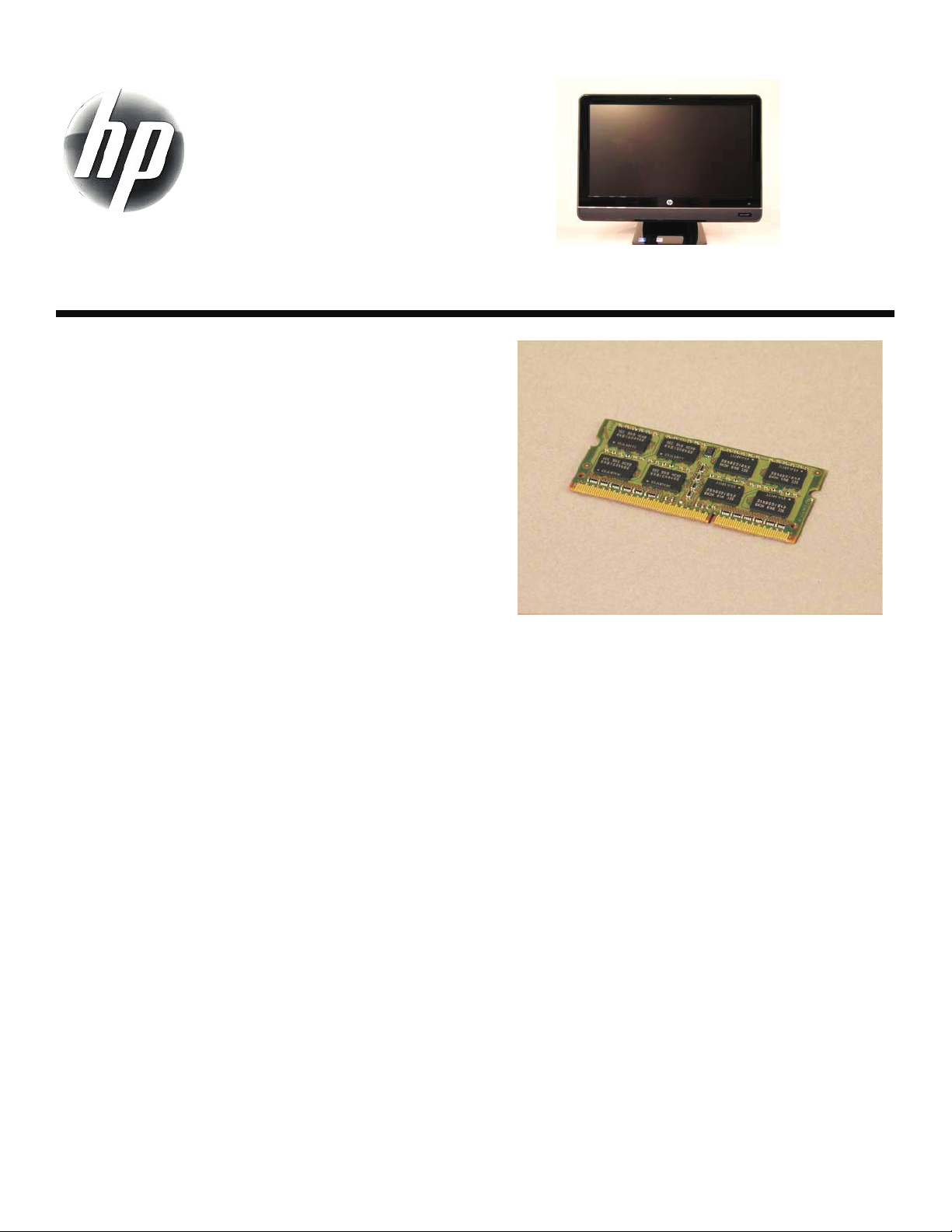
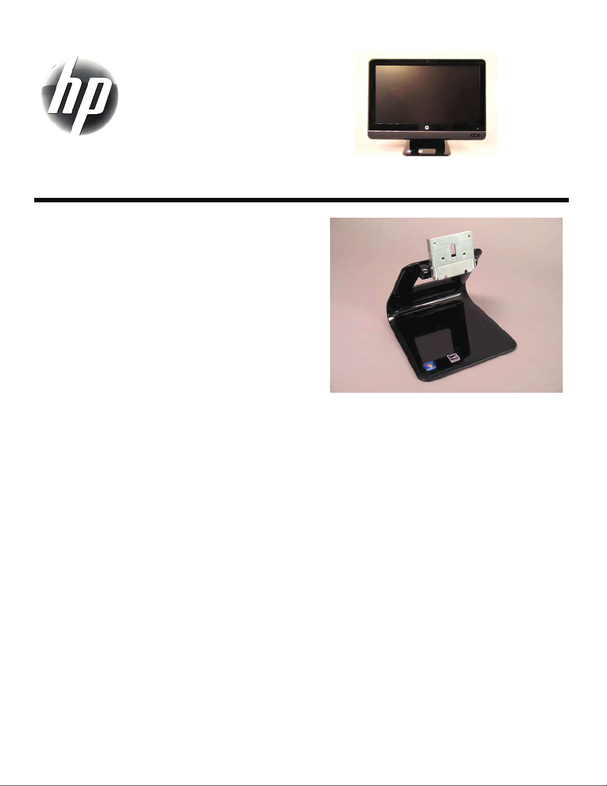
Upgrading and Servicing Guide
Removing the Stand for Wall Mounting ...........2
Before You Begin................................................. 2
Computer Preparation .......................................... 2
Removing the Stand ............................................. 3
Removing and Replacing a CD/DVD Drive .......6
Before You Begin................................................. 6
Computer Preparation .......................................... 6
Removing the CD/DVD Drive ................................ 7
Installing a New CD/DVD Drive............................ 8
Removing and Replacing a Hard Disk Drive ..12
Before You Begin............................................... 12
Computer Preparation ........................................ 12
Removing the Hard Disk Drive............................. 13
Installing a New Hard Disk Drive ........................ 14
599977-001 i
Upgrading or Replacing Memory ..................18
Before You Begin ............................................... 18
Computer Preparation ........................................ 18
Removing the Memory........................................ 19
Installing a New Memory Card............................ 20
Troubleshooting ................................................. 21
Removing and Replacing a Computer Stand ..24
Before You Begin ............................................... 24
Computer Preparation ........................................ 24
Removing the Stand ........................................... 25
Installing a New Stand ....................................... 26
Page 2

ii 599977-001
Page 3

Removing the Stand for Wall
Mounting
Page 4
Removing the Stand for Wall Mounting
5-10 minutes
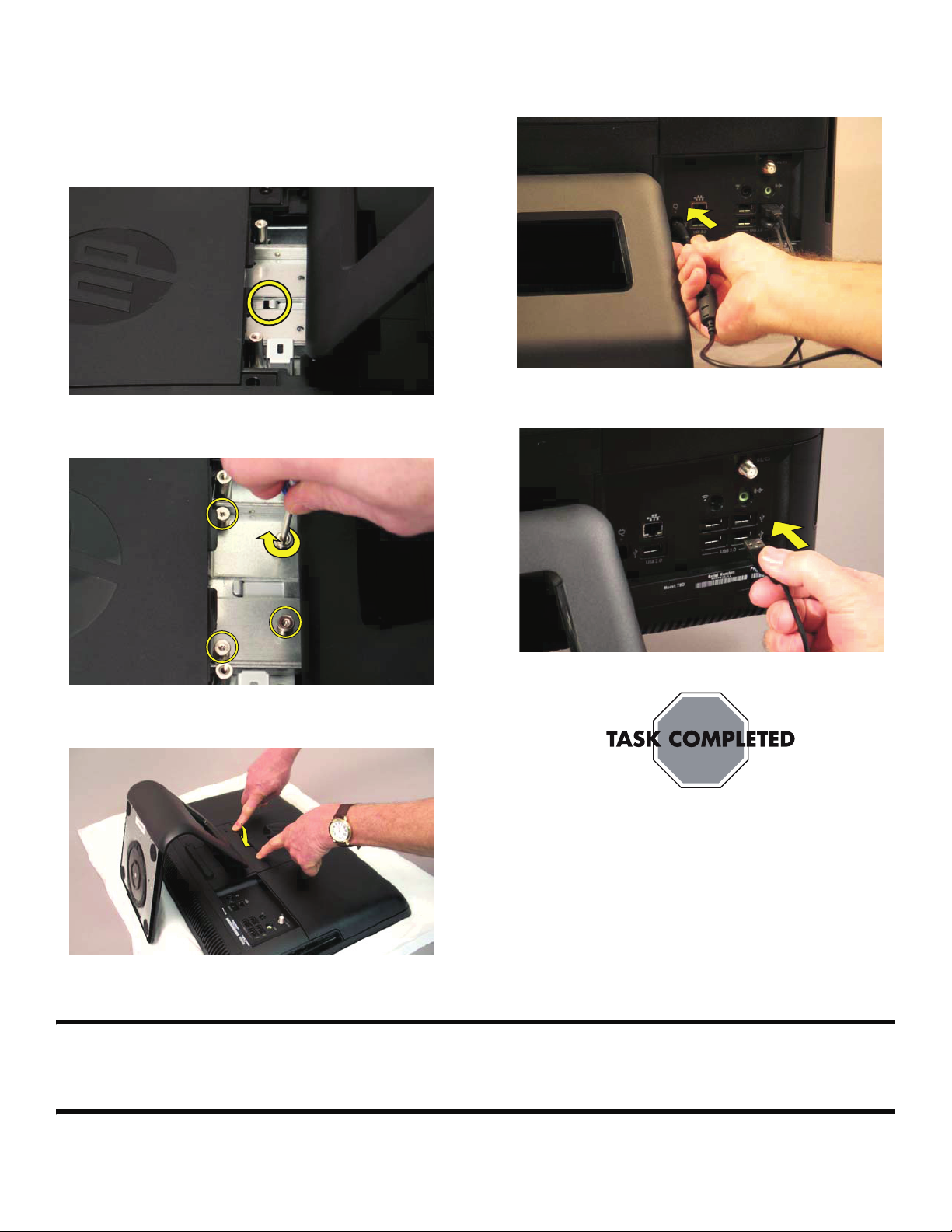
The computer can be mounted on a wall by attaching a
wall-mounting device (sold separately) to the back of the
computer. The four mounting holes on the back of the
computer are compliant with the VESA 100 mm spacing
standard for mounting compatible devices. Before you can
install the wall-mounting device, you need to remove the
stand.
Before You Begin
Observe the following requirements before removing and
replacing the computer stand.
Tools Needed
Flathead screwdriver
Phillips screwdriver #2
CAUTION: Static electricity can damage
the electronic components inside the
computer. Discharge static electricity by
touching the metal cage of the computer
before touching any internal parts or
electronic components.
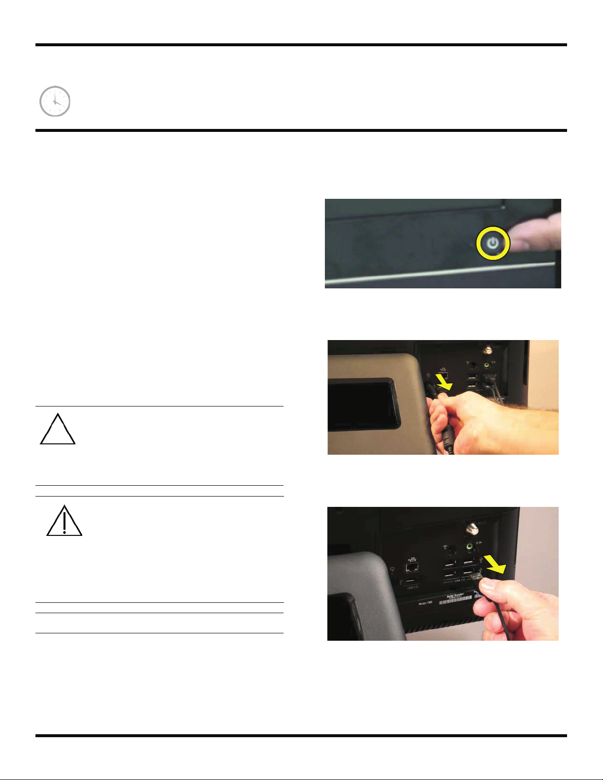
WARNING:
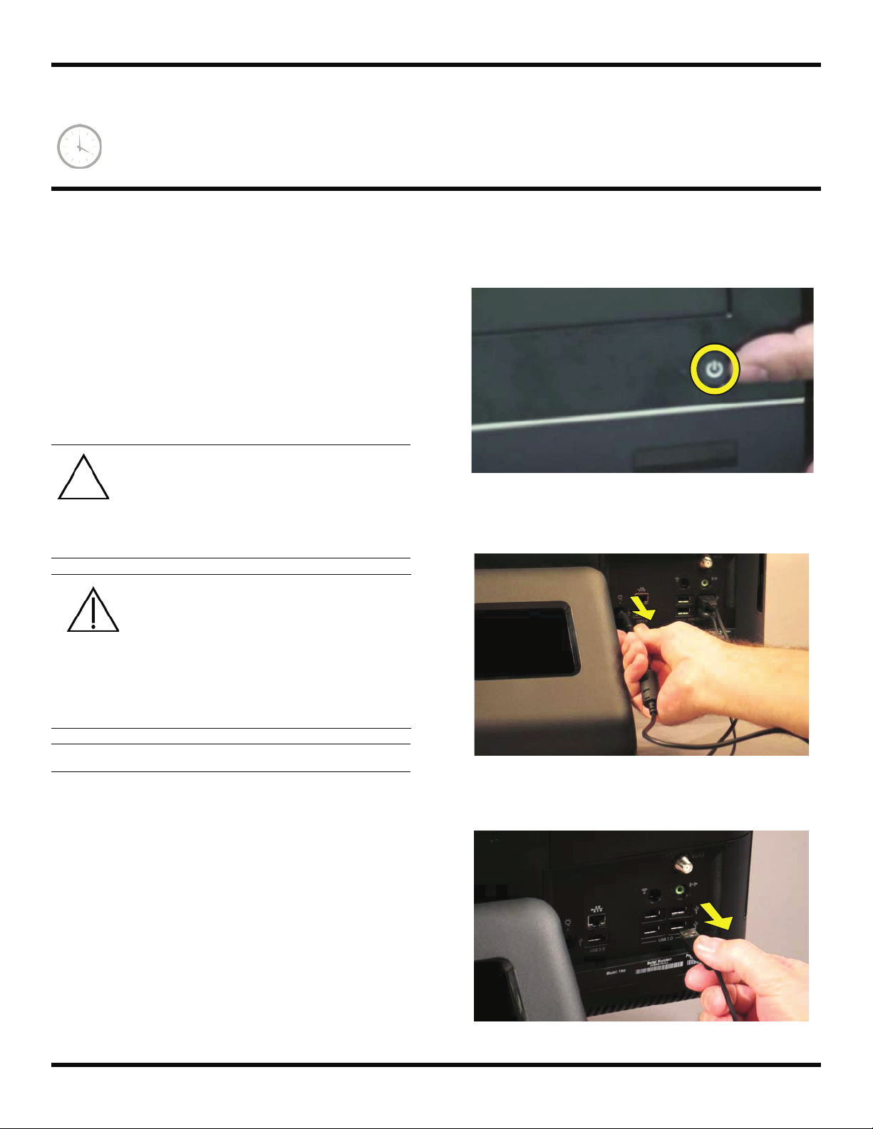
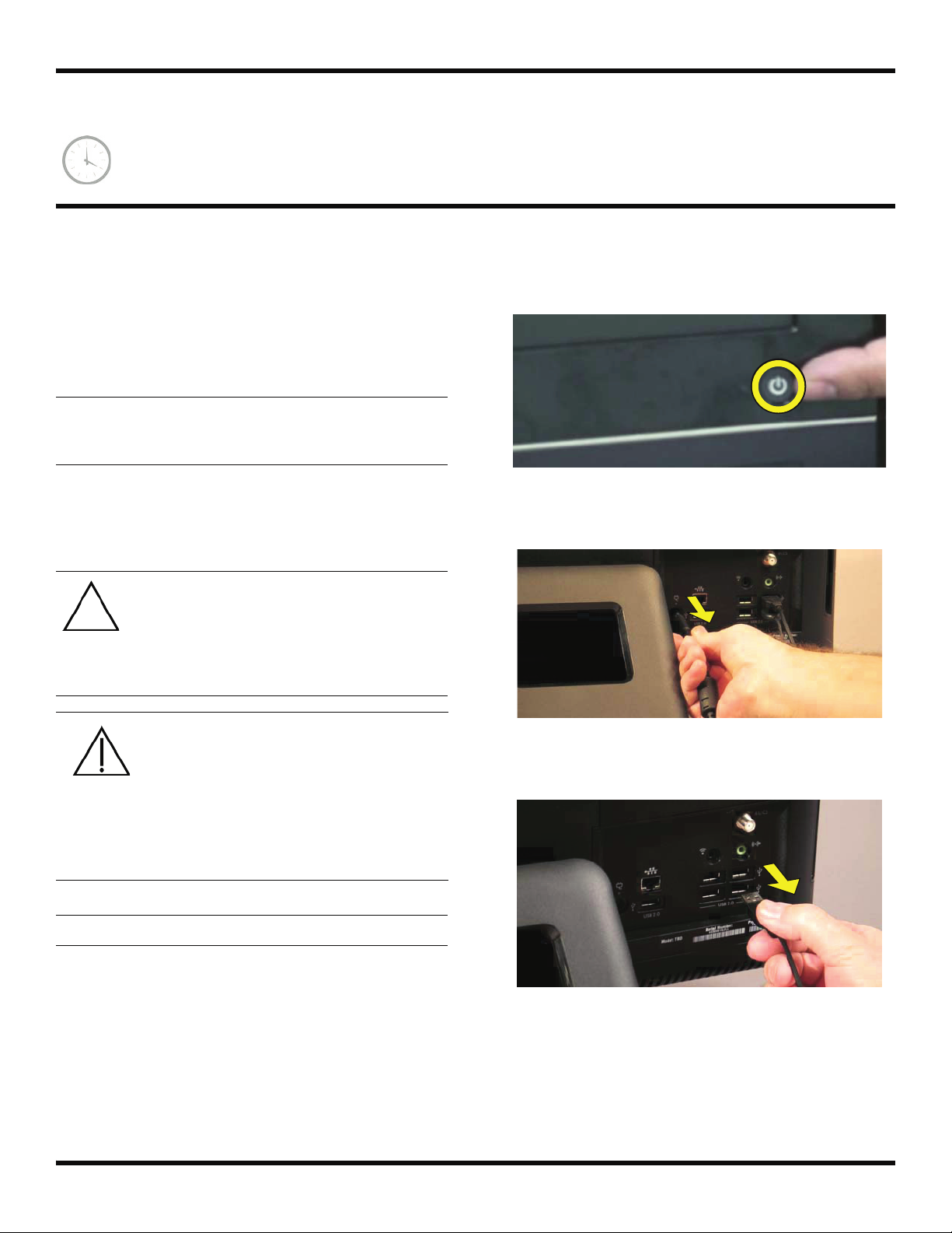
2 Press the power button to turn off the computer.
3 Unplug the computer by disconnecting the power
cord in back.
4 Unplug all attached cables from the back of the
computer.
Never open the cover with the
power cord attached or power
applied. You may damage your
computer.
Avoid touching sharp edges
inside the computer.
IMPORTANT: Computer features may vary by model.
Computer Preparation
1 Remove any media (CD, DVD, and memory cards)
from the computer.
2 599977-001 — Removing the Stand for Wall Mounting
Page 5
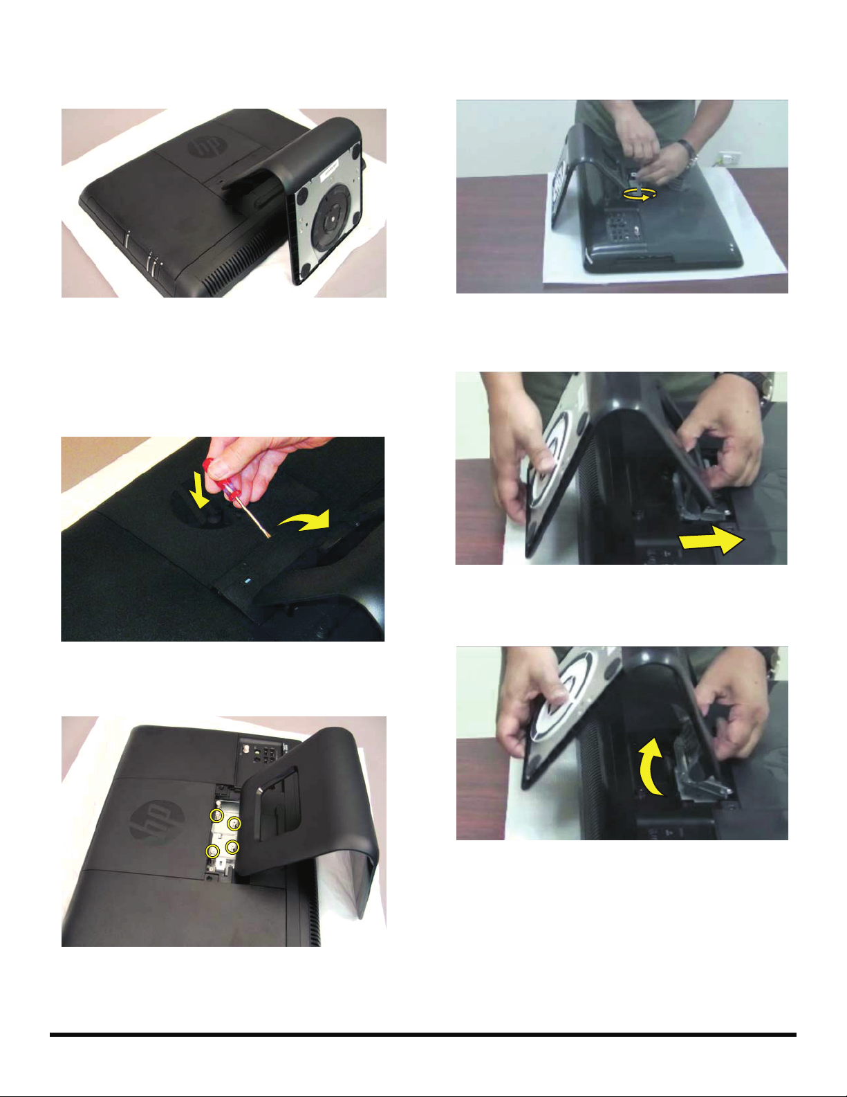
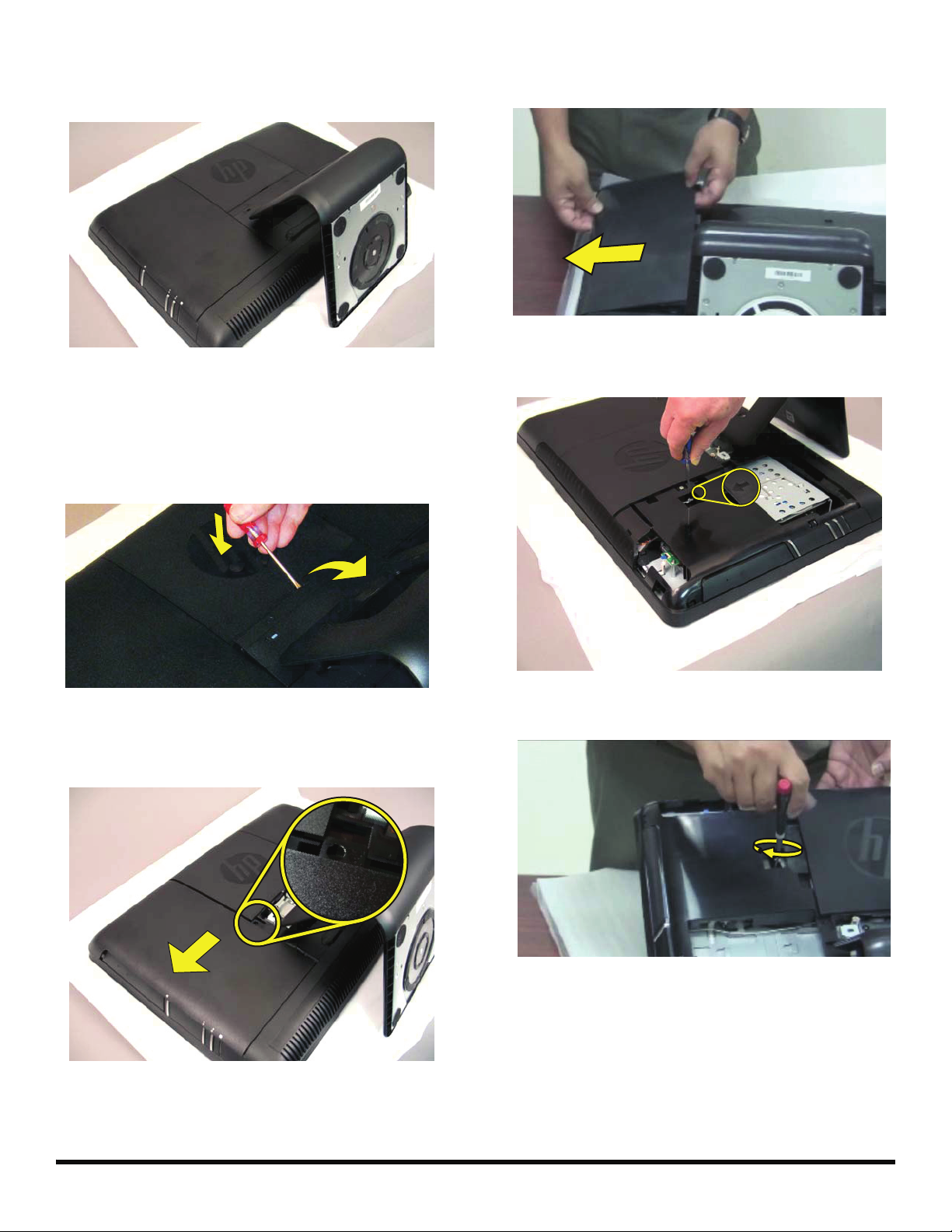
5 Lay the computer down on a flat surface, covered with
a soft cloth to protect the screen from scratches or
other damage.
8 Use a screwdriver to remove the four screws holding
the stand.
Removing the Stand
6 Remove the back cover above the stand at the back of
the computer. Insert a flathead screwdriver or other
object with a flat tip into the slot to pry it off.
7 There are four screws attaching the stand to the
computer.
9 Slide the stand assembly forward slightly, toward the
top of the computer.
10 Lift and slide the stand assembly backwards to
remove it from the computer.
599977-001 — Removing the Stand for Wall Mounting 3
Page 6
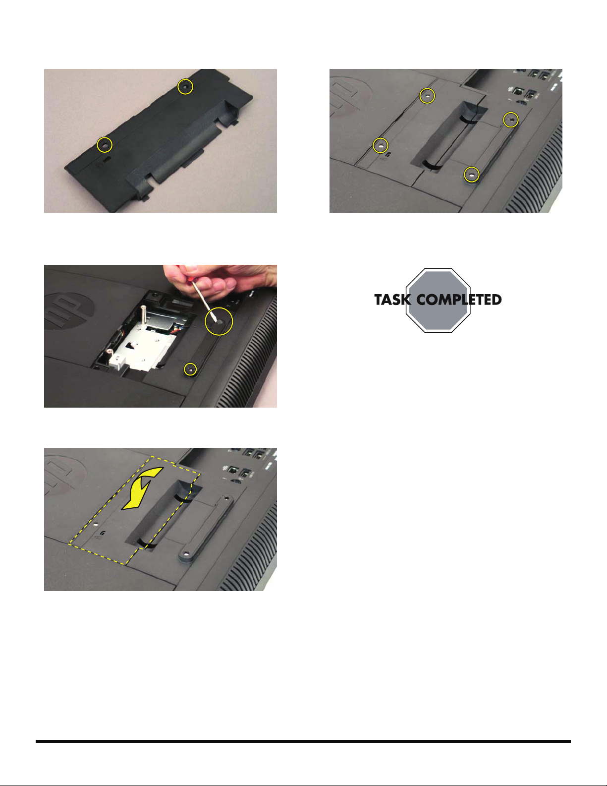
11 Use a flathead screwdriver to remove the plastic tabs
covering the two screw holes on the back cover.
14 There are four holes for screws to be used to attach
the wall mounting device to the computer.
12 Use a flathead screwdriver to remove the plastic tabs
covering the two screw holes below the back cover.
13 Replace the back cover on to the computer.
15 Follow the wall-mounting hardware manufacturer’s
instructions on how to wall-mount the computer.
4 599977-001 — Removing the Stand for Wall Mounting
Page 7
Removing and Replacing a
CD/DVD Drive
Page 8
Removing and Replacing a CD/DVD Drive
10 - 15 minutes
Before You Begin
Observe the following requirements before removing and
replacing the hard disk drive.
Tools Needed
Flathead screwdriver
Phillips screwdriver #1
CAUTION: Static electricity can damage
the electronic components inside the
computer. Discharge static electricity by
touching the metal cage of the computer
before touching any internal parts or
electronic components.
WARNING:
Never open the cover with the
power cord attached or power
applied. You may damage your
computer.
2 Press the power button to turn off the computer.
3 Unplug the computer by disconnecting the power
cord from the back of the computer.
Avoid touching sharp edges
inside the computer.
IMPORTANT: Computer features may vary by model.
4 Unplug all attached cables from the back of the
Computer Preparation
1 Remove any media (CD, DVD, and memory cards)
from the computer.
computer.
6 599977-001 — Removing and Replacing a CD/DVD Drive
Page 9
5 Lay the computer down on a flat surface, covered with
a soft cloth to protect the screen from scratches or
other damage.
Removing the CD/DVD Drive
6 Remove the back cover above the stand at the back of
the computer. Insert a flathead screwdriver or other
object with a flat tip into the slot to pry it off.
8 Slide the side cover off the computer in the direction
indicated by the arrow.
9 Markings on the CD/DVD drive cover indicate the
location of the screw.
7 The left and right side covers on the back of the
computer have a tab with an arrow indicating the
direction to remove each cover.
10 Remove the screw for the CD/DVD drive.
599977-001 — Removing and Replacing a CD/DVD Drive 7
Page 10
11 Insert a finger, or a screwdriver, in the slot and push
the CD/DVD drive out.
12 Slide the CD/DVD drive out of the computer.
Installing a New CD/DVD Drive
NOTE: The replacement CD/DVD drive may not look
exactly the same as the original drive due to different
manufacturers or models. Hewlett-Packard always
provides quality parts that meet or exceed your original
computer specifications.
1 Slide the replacement CD/DVD drive into the
computer, placing the notched edge toward the top of
the computer.
2 Push the CD/DVD drive in until it stops.
3 Replace the screw on the CD/DVD drive.
8 599977-001 — Removing and Replacing a CD/DVD Drive
Page 11

4 Replace the side cover.
5 Replace the back cover above the stand.
8 Reconnect all the cables.
6 Place the computer in an upright position.
7 Plug in the power cord.
599977-001 — Removing and Replacing a CD/DVD Drive 9
Page 12

10 599977-001 — Removing and Replacing a CD/DVD Drive
Page 13
Removing and Replacing a Hard
Disk Drive
Page 14
Removing and Replacing a Hard Disk Drive
10 - 15 minutes
Before You Begin
Observe the following requirements before removing and
replacing the hard disk drive.
IMPORTANT: A hard disk drive is extremely sensitive to
shock impact. Do not bang or drop it. Do not touch the
circuit board. Static electricity can damage the drive.
Tools Needed
Flathead screwdriver
Phillips screwdrivers #1, #2
CAUTION: Static electricity can damage
the electronic components inside the
computer. Discharge static electricity by
touching the metal cage of the computer
before touching any internal parts or
electronic components.
WARNING:
Never open the cover with the
power cord attached or power
applied. You may damage your
computer.
Avoid touching sharp edges
inside the computer.
2 Press the power button to turn off the computer.
3 Unplug the computer by disconnecting the power
cord from the back of the computer.
4 Unplug all attached cables from the back of the
computer.
IMPORTANT: Computer features may vary by model.
Computer Preparation
1 Remove any media (CD, DVD, and memory cards)
from the computer.
12 599977-001 — Removing and Replacing a Hard Disk Drive
Page 15

5 Lay the computer down on a flat surface, covered with
a soft cloth to protect the screen from scratches or
other damage.
Removing the Hard Disk Drive
6 Remove the back cover above the stand at the back of
the computer. Insert a flathead screwdriver or other
object with a flat tip into the slot to pry it off.
8 Slide the side cover off the computer in the direction
indicated by the arrow.
9 Markings on the lower portion of the computer
indicate the location of the screw for the hard disk
drive.
7 The left and right side covers on the back of the
computer have a tab with an arrow indicating the
direction to remove each cover.
10 Use a #1 Phillips screwdriver to loosen the screw on
the hard disk drive cage. (The screw should not be
removed completely.)
599977-001 — Removing and Replacing a Hard Disk Drive 13
Page 16

11 Grasp the metal handle on the hard disk drive cage to
slide the cage in the direction indicated by the arrow
on the cage.
12 Lift out the hard disk drive.
14 Slide the hard disk drive out of the cage.
Installing a New Hard Disk Drive
13 To remove the hard disk drive from the cage, unscrew
the four screws on the cage using a #2 Phillips screw
driver.
NOTE: The replacement hard drive may not look exactly
the same as the original drive due to different
manufacturers or models. Hewlett-Packard always
provides quality parts that meet or exceed your original
computer specifications.
1 Align the hard disk drive so the connectors will be
placed at the notched side of the cage.
14 599977-001 — Removing and Replacing a Hard Disk Drive
Page 17

2 Slide the replacement hard disk drive into the cage.
5 Tighten the screw.
3 Replace the four screws on the hard disk drive cage.
4 Grasp the cage by the handle and slide the hard disk
drive back into the hard disk drive bay until it stops.
6 Replace the side cover.
7 Replace the back cover above the stand.
8 Place the computer in an upright position.
599977-001 — Removing and Replacing a Hard Disk Drive 15
Page 18

9 Plug the power cord.
10 Reconnect all the cables.
16 599977-001 — Removing and Replacing a Hard Disk Drive
Page 19
Upgrading or Replacing Memory
Page 20

Upgrading or Replacing Memory
10 - 15 minutes
Before You Begin
Observe the following requirements before removing and
replacing memory cards.
Tools Needed
Flathead screwdriver
CAUTION: Static electricity can damage
the electronic components inside the
computer. Discharge static electricity by
touching the metal cage of the computer
before touching any internal parts or
electronic components.
WARNING:
Never open the cover with the
power cord attached or power
applied. You may damage your
computer.
Avoid touching sharp edges
inside the computer.
IMPORTANT: Computer features may vary by model.
2 Press the power button to turn off the computer.
3 Unplug the computer by disconnecting the power
cord in back.
4 Unplug all attached cables from the back of the
computer.
Computer Preparation
1 Remove any media (CD, DVD, and memory cards)
from the computer.
18 599977-001 — Upgrading or Replacing Memory
Page 21

5 Lay the computer down on a flat surface, covered with
a soft cloth to protect the screen from scratches or
other damage.
Removing the Memory
6 Remove the back cover above the stand at the back of
the computer. Insert a screwdriver or other object with
a flat tip into the slot to pry it off.
8 Slide the cover off the compute in the direction
indicated by the arrow.
IMPORTANT: If you are removing both cards, you must
remove the upper one before removing the lower one.
9 Use your fingers to press outwards on the retaining
clips at the left and right sides of the top memory card
to release it.
7 The left and right side covers on the back of the
computer have a tab with an arrow indicating the
direction to remove each cover.
10 Holding the memory card by its edges, remove it from
the compartment.
11 If you need to remove the lower memory card, repeat
steps 9 and 10.
599977-001 — Upgrading or Replacing Memory 19
Page 22
Installing a New Memory Card
NOTE: The replacement memory card may not look
exactly the same as the original drive due to different
manufacturers or models. Hewlett-Packard always
provides quality parts that meet or exceed your original
computer specifications.
1 Orient the new memory card so that the notch on the
edge of the card faces forward and is on the right.
4 Replace the side cover.
5 Replace the back cover above the stand.
2 Holding the card by its edges, slide it all the way into
the slot.
3 Make sure the card is pressed all the way into the
socket and then gently push down on the card to snap
it into place.
6 Place the computer in an upright position.
7 Plug in the power cord.
20 599977-001 — Upgrading or Replacing Memory
Page 23
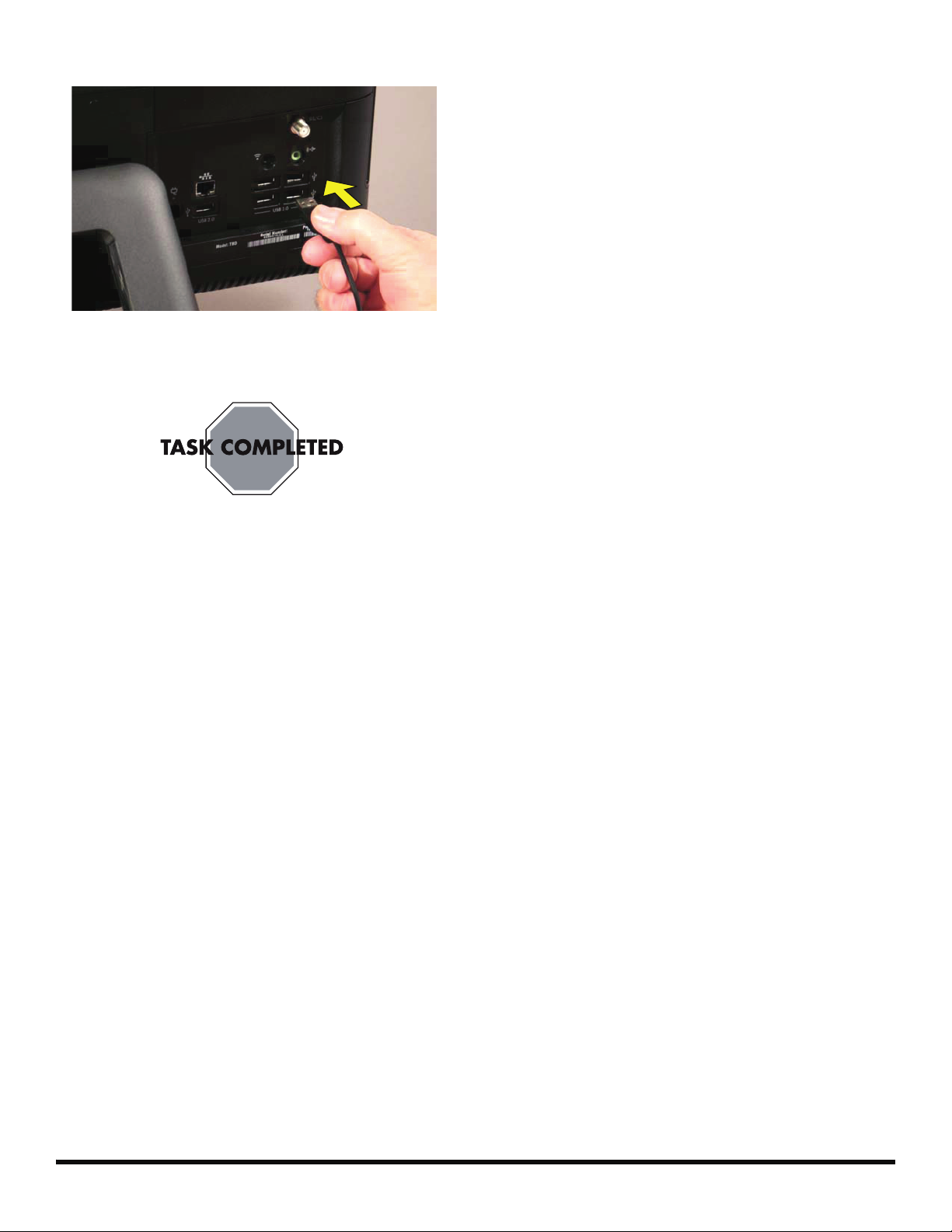
8 Reconnect all the cables.
9 Return the computer to the upright position and turn
on the computer.
Troubleshooting
If the computer displays a memory error after you have
turned it back on, check the following:
Turn the computer off and unplug the power cord,
then open up the memory compartment and make
sure the memory card is firmly seated. To install it
correctly, make sure it inserted all the way into the
compartment and then push down on it to snap it into
place.
Verify that the memory installed is compatible with this
computer. SO-DIMMs are small outline dual inline
memory modules. They are smaller and thinner than
most other DIMMs, so that they take less space in the
case.
SO-DIMM modules must meet the following
requirements:
200-pin DDR2-DIMM
PC2-4200 (533 MHz) DDR2-SDRAM or PC2-
5300 (667 MHz) DDR2-SDRAM
Unbuffered, non-ECC (64-bit) DIMMs
1.8 V memory only
4.0 GB maximum installable memory. Actual
available memory that can be used in Windows
will be less.
Because the memory uses dual channels, you
should use the same DIMM type for both sockets.
599977-001 — Upgrading or Replacing Memory 21
Page 24

22 599977-001 — Upgrading or Replacing Memory
Page 25
Removing and Replacing a
Computer Stand
Page 26

Removing and Replacing a Computer Stand
5-10 minutes
Before You Begin
Observe the following requirements before removing and
replacing the computer stand.
Tools Needed
Flathead screwdriver
Phillips screwdriver #2
CAUTION: Static electricity can damage
the electronic components inside the
computer. Discharge static electricity by
touching the metal cage of the computer
before touching any internal parts or
electronic components.
WARNING:
Never open the cover with the
power cord attached or power
applied. You may damage your
computer.
Avoid touching sharp edges
inside the computer.
2 Press the power button to turn off the computer.
3 Unplug the computer by disconnecting the power
cord in back.
4 Unplug all attached cables from the back of the
computer.
IMPORTANT: Computer features may vary by model.
Computer Preparation
1 Remove any media (CD, DVD, and memory cards)
from the computer.
24 599977-001 — Removing and Replacing a Computer Stand
Page 27

5 Lay the computer down on a flat surface, covered with
a soft cloth to protect the screen from scratches or
other damage.
8 Use a screwdriver to remove the four screws holding
the stand.
Removing the Stand
6 Remove the back cover above the stand at the back of
the computer. Insert a flathead screwdriver or other
object with a flat tip into the slot to pry it off.
7 There are four screws attaching the stand to the
computer.
9 Slide the stand assembly forward slightly, toward the
top of the computer.
10 Lift and slide the stand assembly backwards to
remove it from the computer.
599977-001 — Removing and Replacing a Computer Stand 25
Page 28
Installing a New Stand
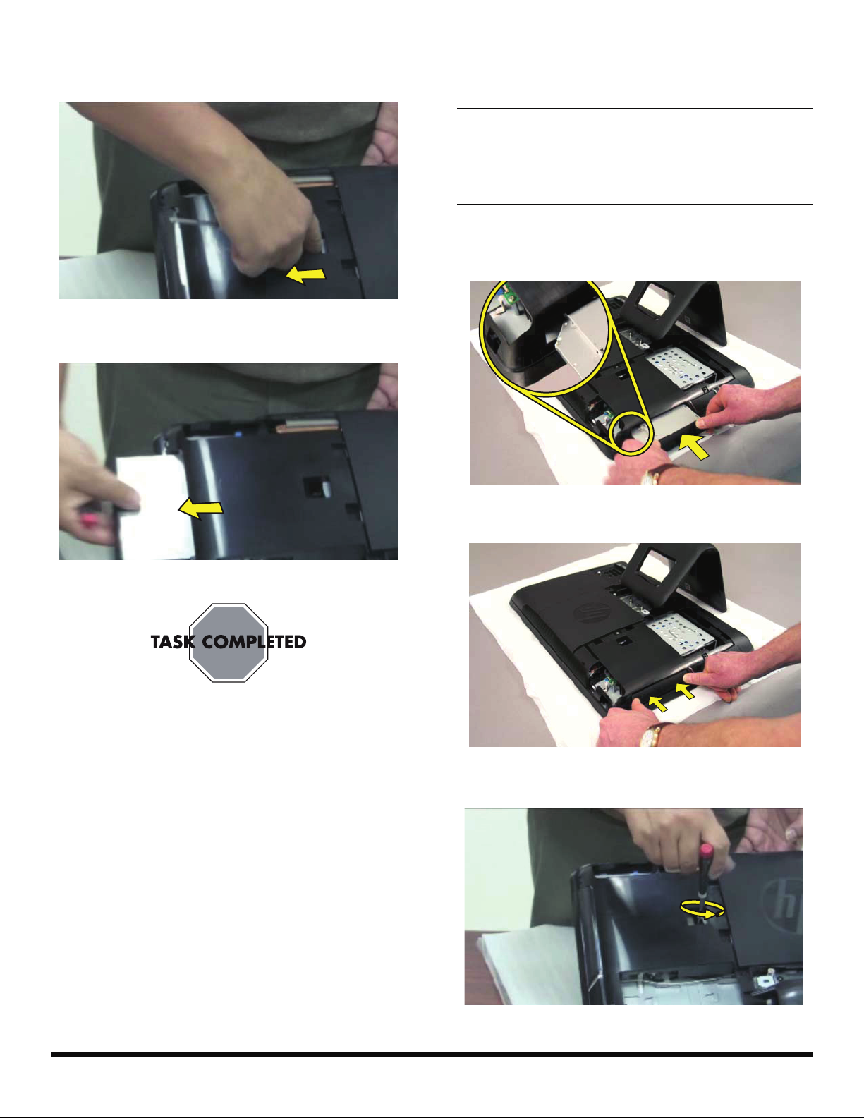
1 Align the slot in the new stand assembly with the tab
on the computer. Slide the stand in until it aligns with
the four screw holes.
2 Replace the four screws.
4 Place the computer in an upright position.
5 Plug in the power cord.
6 Reconnect all the cables.
3 Replace the back cover above the stand.
Copyright © 2010 Hewlett-Packard Development Company, L.P.
The information contained herein is subject to change without notice.
Ver si o n : 1 . 0
 Loading...