

Page 1

Operator’s Reference
Dictionary of Configuring,
Operating, and
Reporting Features
HP AdvanceStack Routers
Page 2

Hewlett-Packard Series 200, 400, and 600
Routers
Operator’s Reference
Page 3

© Copyright HewlettPackard Company 1994.
All rights reserved.
This document contains proprietary information, which
is protected by copyright.
No part of this document
may be photocopied, reproduced, or translated into another language without the
prior written consent of
Hewlett-Packard.
Publication Number
5962-8305
E0794
Edition 1, July 1994
Printed in Singapore
Product Numbers and
Software Version
This guide provides information for Hewlett-Packard
routers running software
with the following version
numbers:
A.08 series
B.08 series
C.08 series
Earlier and later software
versions may operate differently than described in this
manual.
Warranty
The information contained
in this document is subject
to change without notice
HEWLETT-PACKARD
COMPANY MAKES NO
WARRANTY OF ANY
KIND WITH REGARD TO
THIS MATERIAL, INCLUDING, BUT NOT LIMITED TO, THE IMPLIED
WARRANTIES OF MERCHANTABILITY AND
FITNESS FOR A PARTICULAR PURPOSE.
Hewlett-Packard shall not
be liable for errors contained herein or for incidental or consequential
damages in connection with
the furnishing, performance,
or use of this material.
Hewlett-Packard assumes
no responsibility for the use
or reliability of its software
on equipment that is not furnished by Hewlett-Packard.
Hewlett-Packard
8000 Foothills Boulevard
Roseville, California 95747-6588
916-786-8000
Page 4

Operator’s Reference
Preface
Preface
When To Use This Guide
Part I of this guide provides an alphabetical listing of Configuration Editor
parameters and their descriptions, grouped according to their corresponding
entries in the Configuration Menu of the Configuration Editor.
The Configuration Menu of the Configuration Guide
Refer to Part I when you need information on a parameter in order to better
understand how to use it in your router’s configuration.
Part II of this guide provides detailed descriptions o f the following:
The router statistics screens
The Network Command Language Interpreter (NCL) commands
The Event Log messages
The Management Information Base (MIB) variables
3
Page 5

Operator’s Reference
Preface
Refer to Part II when you need to learn the meanings of features in these
areas. (To learn how to use statistics screens, NCL commands, the Event
Log, and the MIB variables, refer to the User’s Guide.)
Coverage Note This manual addresses the entire range of parameters and other soft-
ware features found in Hewlett-Packard routers, including features that
are not found on all router models. Thus, for some routers, such as the
HP Router PR (J2540), certain features described in this manual are not
available in the router. For information on the features available in your
router, refer to the release notes you received with the router or most
recent software upgrade.
Audience
This guide is intended for network mangers and other technicians who
install, configure, and manage routers.
Organization
Part I: Dictionary of Configuration Parameters logically groups the
Configuration Editor parameters int o chapters, according to the options in
the Configuration menu. Each chapter contains an alphabetical listing of the
indicated parameters, along with their corresponding options and descriptions. The individual chapters are:
Chapter 1, ‘‘Global and Session Parameters’’
Chapter 2, ‘‘Software Parameters’’
Chapter 3, ‘‘Lines Parameters’’
Chapter 4, ‘‘Circuits Parameters’’
Chapter 5, “Circuit Group Parameters’’
Chapter 6, ‘‘Bridge Parameters’’
Chapter 7, ‘‘Internet Protocol (IP) Parameters’’
Chapter 8, ‘‘DECnet Parameters’’
Chapter 9, ‘‘SNMP Parameters’’
4
Page 6

Operator’s Reference
Preface
Chapter 10, ‘‘Xerox Network System (XNS) Parameters’’
Chapter 11, ‘‘IPX Protocol Parameters’’
Chapter 12, ‘‘AppleTalk Parameters’’
Chapter 13, ‘‘X.25 Service Parameters’’
Chapter 14, ‘‘V.25 bis Network Mapping Parameters’’
Part II: General Operating Reference provides detailed reference
information on the router’s statistics output, NCL command usage, event
messages, and MIB variables. The individual chapters are:
Chapter 15, ‘‘Statistics’’
Chapter 16, ‘‘Network Command Languague (NCL) Commands’’
Chapter 17, ‘‘Event Log Messages’’
Chapter 18, ‘‘Management Information Base (MIB) Variab les
Appendix A, ‘‘Public Ethernet Type Field Values’’, lists Et hernet packet types
found in the 13th and 14th octets of an Ethernet packet.
Appendix B, ‘‘TCP and UDP Well-Known Port Numbers’’, lists well-known
port numbers used by TCP and UDP.
Appendix C, “Parameter Locator”, is an aid to locating individual parameters
in the Configuration Editor Structure.
The Index includes references to terms and parameters described in this
manual.
Other HP Router Manuals
For a current listing of manuals designed for use with your Hewlett-Packard
router, refer to the Hewlett-Packard Router Products Release Notes shipped
with your router or most recent software update.
5
Page 7

Operator’s Reference
Preface
6
Page 8

Contents
Operator’s Reference
Preface . . . . . . . . . . . . . . . . . . . . . . . . . . . . . . . . . . . 3
When To Use This Guide . . . . . . . . . . . . . . . . . . . . . . . 3
Audience . . . . . . . . . . . . . . . . . . . . . . . . . . . . . . . . 4
Organization . . . . . . . . . . . . . . . . . . . . . . . . . . . . . . 4
Other HP Router Manuals . . . . . . . . . . . . . . . . . . . . . . . 5
Introduction
Part 1 Dictionary of Configuration Parameters
1 Global and Session Parameters
Overview . . . . . . . . . . . . . . . . . . . . . . . . . . . . . . . . . . 1-2
Parameters and Options . . . . . . . . . . . . . . . . . . . . . . . . . 1-4
2 Software Parameters
Overview . . . . . . . . . . . . . . . . . . . . . . . . . . . . . . . . . . 2-2
Parameters and Options . . . . . . . . . . . . . . . . . . . . . . . . . 2-3
3 Lines Parameters
Overview . . . . . . . . . . . . . . . . . . . . . . . . . . . . . . . . . . 3-2
Parameters and Options . . . . . . . . . . . . . . . . . . . . . . . . . 3-3
4 Circuit Parameters
Overview . . . . . . . . . . . . . . . . . . . . . . . . . . . . . . . . . . 4-2
Parameters and Options . . . . . . . . . . . . . . . . . . . . . . . . . 4-5
5 Circuit Group Parameters
Overview . . . . . . . . . . . . . . . . . . . . . . . . . . . . . . . . . . 5-2
Parameters and Options . . . . . . . . . . . . . . . . . . . . . . . . . 5-3
6 Bridge Parameters
Overview . . . . . . . . . . . . . . . . . . . . . . . . . . . . . . . . . . 6-2
Parameters and Options . . . . . . . . . . . . . . . . . . . . . . . . . 6-5
7
Page 9

7 Internet Protocol (IP) Parameters
Overview . . . . . . . . . . . . . . . . . . . . . . . . . . . . . . . . . . 7-2
Parameters and Options . . . . . . . . . . . . . . . . . . . . . . . . . 7-6
8 DECnet Parameters
Overview . . . . . . . . . . . . . . . . . . . . . . . . . . . . . . . . . . 8-2
Parameters and Options . . . . . . . . . . . . . . . . . . . . . . . . . 8-4
9 SNMP Agent Parameters
Overview . . . . . . . . . . . . . . . . . . . . . . . . . . . . . . . . . . 9-2
Parameters and Options . . . . . . . . . . . . . . . . . . . . . . . . . 9-3
10 Xerox Network Systems (XNS) Router Parameters
Overview . . . . . . . . . . . . . . . . . . . . . . . . . . . . . . . . . . 10-2
Parameters and Options . . . . . . . . . . . . . . . . . . . . . . . . . 10-4
11 IPX Protocol Parameters
Overview . . . . . . . . . . . . . . . . . . . . . . . . . . . . . . . . . . 11-2
Parameters and Options . . . . . . . . . . . . . . . . . . . . . . . . . 11-5
12 AppleTalk Parameters
Overview . . . . . . . . . . . . . . . . . . . . . . . . . . . . . . . . . . 12-2
Parameters and Options . . . . . . . . . . . . . . . . . . . . . . . . . 12-5
13 X.25 Service Parameters
Overview . . . . . . . . . . . . . . . . . . . . . . . . . . . . . . . . . . 13-2
Parameters and Options . . . . . . . . . . . . . . . . . . . . . . . . . 13-4
14 V.25 bis Network Mapping
Overview . . . . . . . . . . . . . . . . . . . . . . . . . . . . . . . . . . 14-2
Parameters and Options . . . . . . . . . . . . . . . . . . . . . . . . . 14-3
8
Page 10

Part II General Operating Reference
15 Using the Statistic Screens
AppleTalk Router Statistics Screen . . . . . . . . . . . . . . . . . . . 15-4
Bridge Statistics Screen . . . . . . . . . . . . . . . . . . . . . . . . . 15-6
Buffers Usage Statistics Screen . . . . . . . . . . . . . . . . . . . . . 15-8
Circuit Statistics Screen . . . . . . . . . . . . . . . . . . . . . . . . . 15-10
DECnet Router Statistics Screen . . . . . . . . . . . . . . . . . . . . 15-12
DoD IP Router Statistics Screen . . . . . . . . . . . . . . . . . . . . . 15-14
IPX Router Statistics Screen . . . . . . . . . . . . . . . . . . . . . . . 15-16
Per Second Statistics Screen . . . . . . . . . . . . . . . . . . . . . . . 15-18
XNS Router Statistics Screen . . . . . . . . . . . . . . . . . . . . . . 15-20
16 Using the Network Control Language
Managing Router Operations and Resources . . . . . . . . . . . . . 16-2
Accessing the Management Information Base . . . . . . . . . . . . . 16-30
Accessing the Internet Management Information Base . . . . . . . . 16-40
Accessing a Remote Management Information Base . . . . . . . . . 16-48
Accessing a Foreign Management Information Base . . . . . . . . . 16-51
Accessing Bridging and Routing Tables . . . . . . . . . . . . . . . . 16-54
Managing the Open Shortest Path First Protocol . . . . . . . . . . . 16-72
Blocking and Unblocking Spanning T ree Explorer Frames . . . . . 16-84
Controlling IP-Mapped Circuits for V . 25 bis . . . . . . . . . . . . . . 16-87
Using TFTP To Transfer Operating Code, Configuration,
and NCL Display . . . . . . . . . . . . . . . . . . . . . . . . . . . . 16-93
Using ZModem to Transfer Configuration and NCL Display . . . . . 16-98
17 Event Log Messages
How To Use This Chapter . . . . . . . . . . . . . . . . . . . . . . . . 17-2
at: AppleTalk Event Messages . . . . . . . . . . . . . . . . . . . . . . 17-4
boot: Boot Event Messages . . . . . . . . . . . . . . . . . . . . . . . 17-15
bootp: Network Boot Protocol Event Messages . . . . . . . . . . . . 17-16
cct: Circuit Event Messages . . . . . . . . . . . . . . . . . . . . . . . 17-18
9
Page 11

dev: Device Event Messages . . . . . . . . . . . . . . . . . . . . . . 17-60
dls: Data Link Services Event Messages . . . . . . . . . . . . . . . . 17-69
drs: DECnet Event Messages . . . . . . . . . . . . . . . . . . . . . . 17-74
egp: Exterior Gateway Protocol Event Messages . . . . . . . . . . . 17-79
ip: IP Event Messages . . . . . . . . . . . . . . . . . . . . . . . . . . . 17-86
ipx: IPX Router Event Messages . . . . . . . . . . . . . . . . . . . . 17-92
lb: Bridge Event Messages . . . . . . . . . . . . . . . . . . . . . . . . 17-96
line: Lines Event Messages . . . . . . . . . . . . . . . . . . . . . . . . 17-101
mgr: Manager Event Messages . . . . . . . . . . . . . . . . . . . . . 17-103
ospf: OSPF Event Messages . . . . . . . . . . . . . . . . . . . . . . . 17-105
pm: Port Module Manager Event Messages . . . . . . . . . . . . . . 17-112
ppp: Point-to-Point Protocol . . . . . . . . . . . . . . . . . . . . . . . 17-117
rok: Router Operating Kernel Event Messages . . . . . . . . . . . . 17-120
SMDS Event Messages . . . . . . . . . . . . . . . . . . . . . . . . . . 17-122
tcp: Transmission Control Protocol Event Messages . . . . . . . . . 17-124
telnet: Telnet Event Messages . . . . . . . . . . . . . . . . . . . . . . 17-125
tftp: TFTP and Fget Event Messages . . . . . . . . . . . . . . . . . . 17-126
10
timep: Time Protocol Event Messages . . . . . . . . . . . . . . . . . 17-133
X.25 Event Messages . . . . . . . . . . . . . . . . . . . . . . . . . . . 17-135
xrx: XNS Router Event Messages . . . . . . . . . . . . . . . . . . . . 17-147
zmodem: Zmodem Event Messages . . . . . . . . . . . . . . . . . . . 17-149
18 Management Information Base Variables
alarm: Alarm Information Base . . . . . . . . . . . . . . . . . . . . . 18-3
at: AppleTalk Information Base . . . . . . . . . . . . . . . . . . . . . 18-4
atmib: AppleTalk MIB Information Base . . . . . . . . . . . . . . . . 18-9
buf: Buffers Information Base . . . . . . . . . . . . . . . . . . . . . . 18-12
cct: Circuits Information Base . . . . . . . . . . . . . . . . . . . . . 18-14
chassis: Chassis Information Base . . . . . . . . . . . . . . . . . . . 18-43
config: Configuration Information Base . . . . . . . . . . . . . . . . 18-47
dev: Device Information Base . . . . . . . . . . . . . . . . . . . . . . 18-52
Page 12

decnet: DECnet Configuration Information Base . . . . . . . . . . . 18-53
dls: Data Link Services Information Base . . . . . . . . . . . . . . . 18-55
drs: DECnet Circuit Group Information Base . . . . . . . . . . . . . 18-58
echo: Echo Service Information Base . . . . . . . . . . . . . . . . . 18-60
egp: EGP Information Base . . . . . . . . . . . . . . . . . . . . . . . 18-61
hw: Hardware Information Base . . . . . . . . . . . . . . . . . . . . 18-63
ip: IP Information Base . . . . . . . . . . . . . . . . . . . . . . . . . . 18-64
ipx: IPX Information Base . . . . . . . . . . . . . . . . . . . . . . . . 18-68
isdn: ISDN (V.25 bis) Information Base . . . . . . . . . . . . . . . . . 18-70
key: Key Information Base . . . . . . . . . . . . . . . . . . . . . . . 18-74
lb: Bridge Information Base . . . . . . . . . . . . . . . . . . . . . . . 18-75
lbmib: Bridge Address Table Information Base . . . . . . . . . . . . 18-79
log: Event Log Information Base . . . . . . . . . . . . . . . . . . . . 18-81
mem: Memory Information Base . . . . . . . . . . . . . . . . . . . . 18-82
mgr: Manager Information Base . . . . . . . . . . . . . . . . . . . . 18-83
mib: Internet MIB . . . . . . . . . . . . . . . . . . . . . . . . . . . . . 18-84
name: Name Information Base . . . . . . . . . . . . . . . . . . . . . 18-85
pm: Port Module Manager Information Base . . . . . . . . . . . . . 18-86
proprietary: Proprietary Information Base . . . . . . . . . . . . . . . 18-88
rok: Router Operating Kernel Information Base . . . . . . . . . . . . 18-89
snmp: SNMP Information Base . . . . . . . . . . . . . . . . . . . . . 18-90
svc: System Services Information Base . . . . . . . . . . . . . . . . 18-91
tcp: TCP Information Base . . . . . . . . . . . . . . . . . . . . . . . 18-92
telnet: Telnet Information Base . . . . . . . . . . . . . . . . . . . . . 18-95
tftp: TFTP Information Base . . . . . . . . . . . . . . . . . . . . . . 18-97
timep: Time Protocol Information Base . . . . . . . . . . . . . . . . 18-99
timer: Timer Information Base . . . . . . . . . . . . . . . . . . . . . 18-100
xrx: Xerox XNS Information Base . . . . . . . . . . . . . . . . . . . 18-101
x25: X.25 Information Base . . . . . . . . . . . . . . . . . . . . . . . 18-105
11
Page 13

A Parameter Finder
How To Use the Parameter Finder . . . . . . . . . . . . . . . . . . . A-2
1. System . . . . . . . . . . . . . . . . . . . . . . . . . . . . . . . . . . A-4
2. Software & 3. Lines . . . . . . . . . . . . . . . . . . . . . . . . . . A-5
4. Circuits . . . . . . . . . . . . . . . . . . . . . . . . . . . . . . . . . A-6
5. Circuit Groups . . . . . . . . . . . . . . . . . . . . . . . . . . . . . A-12
6. Bridge . . . . . . . . . . . . . . . . . . . . . . . . . . . . . . . . . . A-13
7. DoD Internet Router . . . . . . . . . . . . . . . . . . . . . . . . . . A-16
8. DECNET IV Routing Service . . . . . . . . . . . . . . . . . . . . . A-23
9. SNMP Sessions . . . . . . . . . . . . . . . . . . . . . . . . . . . . . A-25
10. Xerox Routing Service . . . . . . . . . . . . . . . . . . . . . . . . A-26
11. IPX Routing Service . . . . . . . . . . . . . . . . . . . . . . . . . A-28
12. AppleTalk Router . . . . . . . . . . . . . . . . . . . . . . . . . . . A-31
13. X.25 Network Service . . . . . . . . . . . . . . . . . . . . . . . . . A-33
14. V.25 bis Network Mapping . . . . . . . . . . . . . . . . . . . . . . A-35
Index
12
Page 14

Introduction: How To Use the Dictionary
of Configuration Parameters
Introduction
Page 15
Access to the
Configuration
Editor
Operator’s Reference
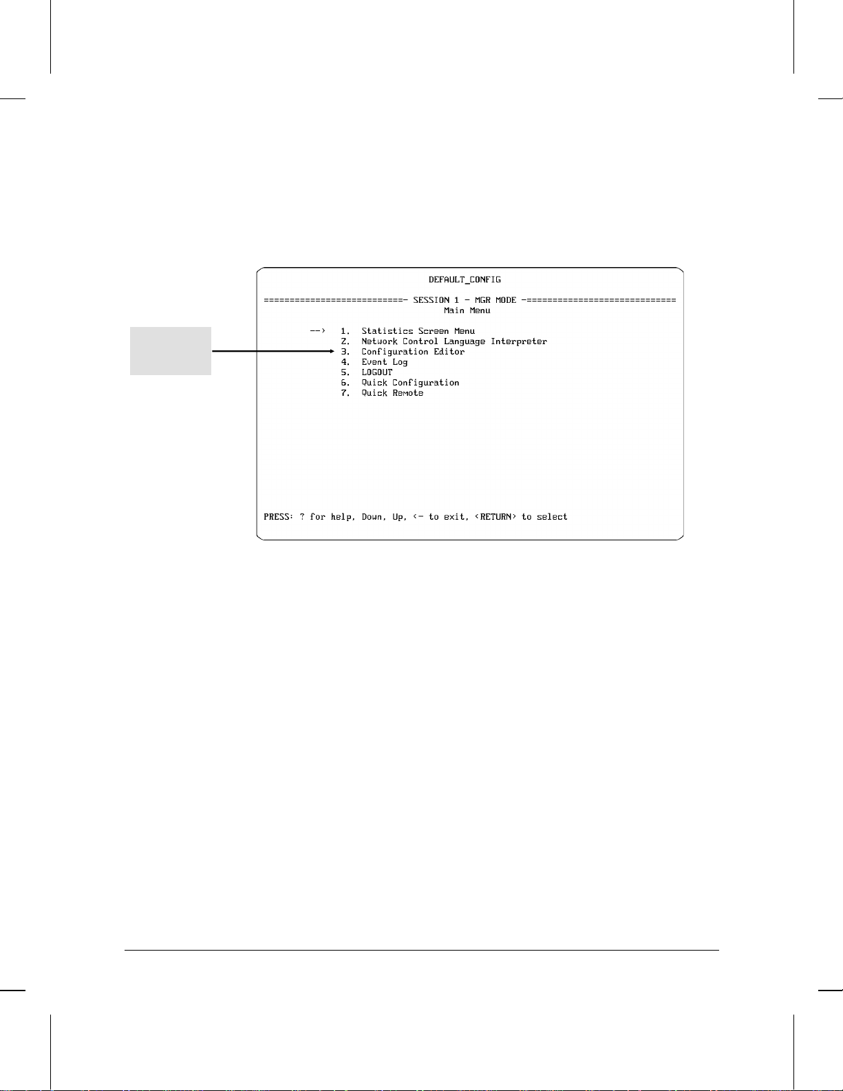
Part I is a dictionary reference of the Parameters found in the Configuration
Editor, which is accessable from the Main menu (or by using the [/] [M] hot-
key combination in Quick Configuration).
Accessing the Configuration Editor from the Main Menu
2
Page 16
Operator’s Reference
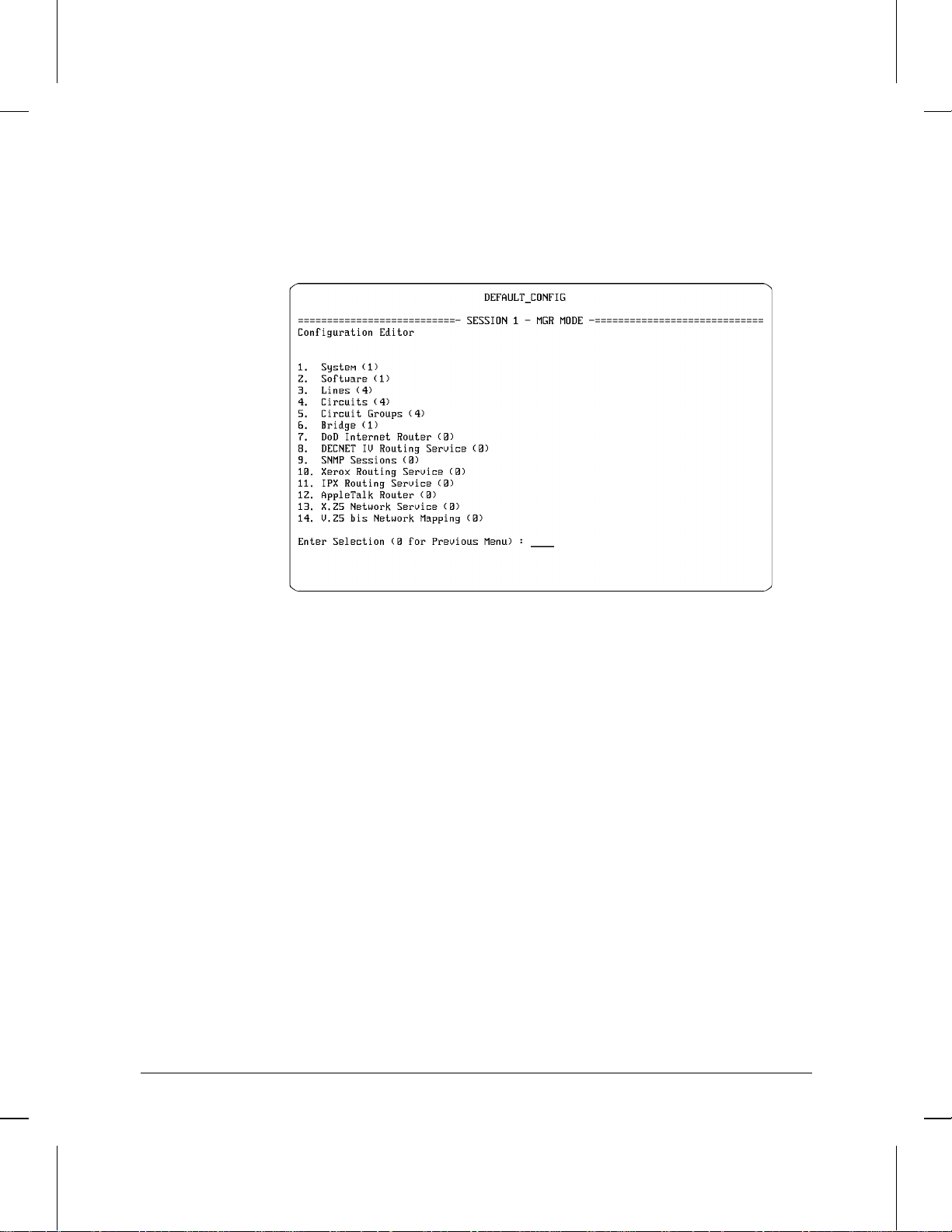
Part I is divided into fourteen chapters correspon ding to the options listed in
the Configuration menu:
Figure 1-1. The Configuration Menu
3
Page 17

Operator’s Reference
To find a parameter description, turn to the chapter corresponding to the
Configuration menu option containing that parameter. Then locate the parameter by finding it in its alphabetic order. (You can also locate the parameter description by using the page/parameter listing at the beginning of each
chapter.)
Within each chapter, the parameters are listed alphabetically, with descriptions of their functions and a ssociated options. For example, the following
sample of dictionary entries describes the Quality of Service and Remote Address parameters, and include:
The parameter names
Any applicable options for parameter settings
A description of each parameter and each parameter option
Any default settings
4
Page 18

Operator’s Reference
Example of Dictionary Entries in Operator’s Reference
Quality of Service
Parameter Name
Options for the
Quality of Service
Parameter
Remote Address
Specifies the link-level control. It always mus t remain set to LLC1, the default, for
802.3, 802.5, and PPP circuits.
Default: LLC1
LLC1
Datagram service; best-effort delivery.
LLC2
Reliable service, provides link-level control that includes error detection and error
recovery by retransmission. Results in these additional parameters:
Retry Counter Retry Timer
Connect Retries Link Idle Timer
Modulus Window Size
Accepts a unique decimal value from 00 to 99. Be sure to reverse local and remote
address values when you configure the device at the other end of the PPP circuit.
Default: 07
Range: 00 to 99
Default Setting for Quality of Service
Selecting the LLC2 option for Quality
of Service causes these six other
parameters to appear. Their
descriptions are listed
alphabetically in this chapter.
5
Page 19

Page 20

Part I
Part I
Dictionary of Configuration
Parameters
Page 21

Part I
Page 22

1
Global and Session Parameters
Page 23

Global and Session Parameters
Overview
Overview
Access to Global and Session Parameters
1-2
Figure 1-1. Access to Global Parameters in the Configuration Menu
Global Parameters: These specify how the router initializes its
services.
Page Global Parameters
1-4 Auto Enable
1-4 Automatic Reboot
1-5 Daylight Time Rule
1-8 Screen Refresh Rate
1-9 System Contact
1-9 System Name
1-9 System Location
1-9 Timezone
Page 24

Global and Session
Parameters
1
Global and Session Parameters
Overview
Session Parameters: Define the interface between the router and I/O
devices, such as a console, modem, and Telnet.
Page Session Parameters
1-4 Baud Rate
1-5 Bit / Char .
1-5 Connection inactivity time (min)
1-6 Event Filter Level
1-7 Flow Control
1-7 Modem connection time (sec)
1-7 Modem disconnection time (sec)
1-8 Modem lost receive ready time (msec)
1-8 Parity
1-8 Session Mode
1-8 Screen Refresh Rate
1-8 Stop Bits
1-9 Terminal
1-9 Timezone
1-3
Page 25

Global and Session Parameters
Parameters and Options
Parameters and Options
Auto Enable
Automatic Reboot
Baud Rate
Determines whether various system services and application modules initialize
automatically when the router boots.
Default: Yes
No
Disables all protocol-specific Auto Enable parameters for all software modules and
system services. Y ou wi ll need to enable each service or software module with the
NCL (Network Control Language Interpreter) Enable command after the router
boots.
Yes
Conditionally enables all protocol-specific Auto Enable parameters for all software
modules and system services.
Enables or disables automatic router booting after a software crash.
Default: No
No
Disables automatic rebooting—the router must be rebooted manually.
Yes
Enables automatic rebooting—the router starts operation with its bridging and
routing applications enabled if booting is successful. Your console screen stops at
the copyright screen, displays “crash” information about the cause of the cr ash,
and waits for you to type the customary password or any key before you can use
the console.
Sets the data transmission speed (baud rate) for router connect sessions initiated
through the Console port.
Other Options
Beginning day
1-4
Speed Sense
Default: Speed Sense
Automatically detects the baud rate of the remote terminal device and sets the
router to the same baud rate.
300, 600, 1200, 2400, 4800, 9600, 19200, 38400
Note: If the router is set to a fixed baud rate, the terminal device connected to the
router must be set to the same baud rate.
Assigns a day of the week to apply the time adjustment when preparing a userdefined daylight savings time rule.
Default: Sunday
Page 26

Global and Session
Parameters
1
Global and Session Parameters
Parameters and Options
Beginning month
Bit / Char.
Connection
Inactivity Time
Options:
Options
Sunday, Monday, Tuesday, W ednesday, Thursday, Friday, Saturday
Note: If Beginning Day is set to Sunday, the router compensates for daylight
savings time at 2 a.m. on that Sunday. If Beginning day is not set to Sunday, the
router makes the time correction at 2 a.m. on the first Sunday following the
specified day.
Assigns the month of the year to correct for daylight savings time when preparing a
user-defined daylight savings time rule.
Default: April
January, February, March, April, May, June, July, August, September, October,
November, December
Sets the number of data bits in each ASCII character received or transmitted over
the Console port by the router. The terminal device or remote modem connected to
the Console port must be set to a matching number of data bits.
Default: 8
8
8 data bits
7
7 data bits
Sets the number of minutes of no activity detected on the Console port before the
router terminates a communication session. When the time period elapses, the
router logs off the user if a terminal device is connected to the port or sends a hangup string if a modem is connected to the port.
Default: 0 (The router ignores inactivity on the Console port)
Options
Daylight Time Rule
Alaska
0, 1, 5, 10, 15, 20, 20, 30, 60, 120, 1080.
Applies the daylight savings time rule used by the Internet RFC 868 Time protocol.
If the Time protocol is enabled with IP routing and a timeserver is available, the
day light savings time correction is applied after the router is powered on or
booted.
Default: None
Applies the daylight savings time rule observed in Alaska local time.
None
Disables corrections for daylight savings time.
1-5
Page 27

Global and Session Parameters
Parameters and Options
Canada and
Continental US
Middle Europe
and Portugal
Southern Hemisphere
User defined
Western Europe
Ending month
Options
Ending day
Applies the daylight savings time rule observed in Canada and the continental
U.S.A..
Applies the daylight savings rule observed in middle Europe and Portugal.
Applies the daylight savings time rule observed in the southern hemisphere.
Displays a screen with four parameters for defining a custom dayli gh t savings time
rule. Use this option to define a daylight savings time rule if one of the other
parameter options does no meet your requirements. For additional information,
refer to “Beginning Month,” “Beginning Day,” “Ending Month,” and “Ending Day.”
Applies the daylight savings rule observed in western Europe.
Assigns the month in which to return to standard local time when defining a
custom daylight savings time rule.
Default: October
January, February, March, April, May, June, July, August, September, October,
November, December
Assigns the day on which to return to standard local time when defining a custom
daylight savings time rule.
Default: Sunday
Event Filter Level
Debug Events
1-6
Options
Sunday, Monday, Tuesday, W ednesday, Thursday, Friday, Saturday
Note: If Ending day is set to Sunday, the router makes the correction at 2 a.m. on
that day. If Ending day is not set to Sunday, the router makes the correction at
2 a.m. on the first Sunday after the specified day.
Determines which event messages are automatically displayed on the console.
Major A service has appeared or disappeared.
Performance A service has upgraded or degraded.
Warning A service has behaved unexpectedly.
Information General system information
Debug Installation and diagnostic information
Default: Show All Events
Sends all event messages.
Page 28

Global and Session
Parameters
1
Global and Session Parameters
Parameters and Options
Just MAJOR
PERF and MAJOR
Show All Events
Flow Control
Robust XON/XOFF
Drop All
Not INFO
None
XON/OFF
Sends no event messages.
Sends major event messages only.
Sends major, performance, and warning event messages.
Sends major and performance event messages.
Sends major, performance, warning, and information event messages.
Enables XON/XOFF flow control and sets the type of XON/XOFF flow control for
connect sessions made through the router Console port.
XON/XOFF flow control is a software method of controlling flow control
negotiation, and CTS/RTS is the hardware method of controlling flow control
negotiation. The flow control negotiation method used by the remote device must
match the router setting.
Default: XON/XOFF
Disables XON/XOFF software flow control and uses CTS/RTS hardware flow
control instead.
Enables XON/XOFF software flow control.
Enables XON/XOFF software flow control and sends out periodic XON signals
when the flow of data stops and the router expects to receive more data
(checksum failure). For example, the remote connection might have dropped (lost)
an XON signal sent by the router and could be waiting for the arrival of the lost
signal before transmitting more data. In this case, data transmission resumes when
the remote end of the connection receives the next XON signal.
Modem
Connection Time
Options
Modem
Disconnection Time
Sets the number of seconds to wait for data mode and clear to send and receiver
ready signals after asserting request to send and terminal ready signals.
Default: 60
0, 1, 5, 10, 15, 20, 25, 30, 60, 120, 255
Note: The router waits forever for the modem to connect when the parameter
setting is 0 (zero).
Sets the wait period, in seconds, for the Cons ole port after the modem disconnects
and before the modem reconnects.
1-7
Page 29

Global and Session Parameters
Parameters and Options
Default: 0.5
Options
Modem Lost Receive
Ready Time
Options
Parity
Options
Screen Refresh Rate
0.5, 1, 5, 10, 15, 20, 30, 60
Sets the number of milliseconds the receiver ready signal drops before the router
disconnects the modem attached to the Console port. This is a form of debouncing
the receiver ready signal.
Default: 400
0. 25, 50, 100, 200, 400, 800, 1600, 2550
Note: The modem waits forever when the time period is set to 0 (zero)
Assigns a value to the eighth bit of each ASCII character transmi tted by the router.
Match your console’s requirements.
Default: None (no parity)
None, Even, Odd
Note: Most terminals do not operate with an odd or even parity if Bit/Char is set to 8.
Matches the vertical frequency rate (Hz) of the router end of the connection to the
vertical frequency rate of the terminal de vice connected to Console port or remote
modem.
Default: 3 (Hz)
Session Mode
Stop Bits
1-8
Options
Telnet
User
1, 3, 5, 10, 20, 30, 45, 60
Toggles the Console port connection between standard User mode and Telnet
mode.
Default: User
Places the Console port connection in Telnet mode.
Places the Console port in standard User mode.
Specifies the number of bits following each ASCII character received or
transmitted by the router. Match your console requirements.
Default: 2
Page 30

Global and Session
Parameters
1
Global and Session Parameters
Parameters and Options
System Contact
System Location
System Name
System Session
Options
1, 1.5, 2
Accepts an ASCII character string identifying the pe rson responsible for the router.
For example: John Smith, Building 6.
Accepts an ASCII character string identifying the physi c al location of the router.
For example: Technology Center, Engineering Lab.
Accepts a 15 character string (with no spaces) naming the ro uter as a node in the
network.
Default: DEFAULT_CONFIG
Optional selection for displaying additional parameters for configuring the Console
port connection. Remote users can enable this option to display the session
parameters when they want to optimize the connection with the router. For
example, the user might want to change the baud rate of the Console port.
Default: 0
0
Displays no parameters.
1
Displays these additional parameters:
Baud Rate Bit/Char
Connection Inactivity Time Event Filter
Flow Control Modem Connection Time
Modem Disconnection Time Modem Lost Receive Ready Time
Parity Screen Refresh Rate
Session Mode Stop Bits
Terminal
Note: A smaller set of parameters are displa yed if you later toggle to Telnet
Session Mode.
Terminal
VT100
Timezone
Sets the router to match the type of terminal emulation supported by the remote
device connected to the Console port.
Default: VT100
ANSI
ANSI terminal emulation.
VT100 terminal emulation.
Sets the local time offset from GMT (Grenwich Mea n Time) for the time protocol,
which automatically sets the clock when the router boots.
1-9
Page 31

Page 32

2
Software Parameters
Page 33

Software Parameters
Overview
Overview
Access to Software Parameters
2-2
Figure 2-1. Access to Software Parameters in the Configuration Menu
Software Parameter: Enables the application modules--the bridging
and specific routing services on the router. You must enable each
application to be used. Any service that you enable can be used on any
port.
Page Software Parameter
2-3 Protocol
Page 34

Parameters and Options
2
Software Parameters
Parameters and Options
Protocol
Options
Adds or deletes the protocol (service) you want to enable or disable on the router.
Default: Bridge
Bridge, DoD IP Router, DECnet Router, Xerox (XNS) Router, IPX Router,
AppleTalk Router
Parameters
Software
2-3
Page 35

Page 36

3
Lines Parameters
Page 37

Lines Parameters
Overview
Overview
Access to Lines Parameters
3-2
Figure 3-1. Access to Lines, Circuits, and Circuit Group Parameters
Line Parameters: Describe the physical (level 1) connections
between the router and local area networks and/or long-haul transmission facilities. The lines for the ports are initially established with
default attributes configured.
Page Line Parameters
3-3 Bridge Type
3-3 Circuit Name
3-3 Clock Source
3-4 Clock Speed
3-4 Connector
3-4 Physical Access Method
3-5 Ring Interface
Page 38

Parameters and Options
Lines
Parameters
3
Lines Parameters
Parameters and Options
Bridge Type
Encapsulating
Circuit Name
Specifies the FDDI bridge type when FDDI is selected as the Physical Access
Method.
Default: Encapsulating
Translating
Identifies the circuit for the associated connector. The defa ult startup and default
Quick Configuration set this parameter to the name of the connector. This name
should also appear on your network map. In HP Series 200 and 400 routers, the
default circuit name includes the ci rc uit type and related port number (1 -- 4). For
example:
ETHER1 The first 802.3/Ethernet port configured
WAN2 The second WAN port configured
In HP Series 600 routers, the default circuit name also includes the number of the
slot in which the associated port is installed. For example:
ETHER21 The first 802.3/Ethernet port in the second slot
WAN32: The second WAN port in the third slot
Note: You can change a circuit name to nearly any character sequence you want, but
it is recommended that you use names that identify the associated slot (if any) and
port numbers for each circuit.
Clock Source
External
Internal
Identifies the origin of synchronous timing signals.
Default: External
Select this option if an external network device supplies the timing signals over
synchronous lines. In virtually all field applications, another network device supplies
the timing signals. The send timing (ST) signal is looped back through the transmit
timing (TT) output line. The upper range for external clocking is 2 megabits per
second, and the aggregate throughput is 4 megabits per second.
Select this option if the router has to supply the timing signals. Some test
environments do require an external clock. The internal clock signal drives the
transmit timing (TT) output line. If you set Clock Source to Internal, also set the
Clock Speed parameter.
3-3
Page 39

Lines Parameters
Parameters and Options
Clock Speed
Connector
Options
Sets the speed on the internal clock if the Clock Source parameter is set to
Internal. Choose one of the following options:
Default: 56 K (bits per second)
1.2 K, 2.4 K, 4.8 K, 7.2 K, 9.6 K, 19.2 K, 32 K, 38.4 K, 56 K, 64 K, 125 K, 230.4 K
420 K, 625 K, 833 K, 1.25 M
Note: The Clock Speed limit for RS-232 cables connected to the router’s WAN ports is
230.4Kbps.
Identifies the physical port interfaced to a synchronous line.
Examples of defaults:
Line Type Series 200/400 Series 600
(First Port of Type) (First Port of Type)
Ethernet/802.3: ETHER1 ETHER21 (slot 2, port 1)
Synchronous: WAN1 WAN31 (slot 3, port 1)
Token Ring: TOKEN1 TOKEN41 (slot 4, port 1)
FDDI: FDDI1
Note: The options displayed for Connector vary depending on th e type of line you
are configuring.
Physical Access
Method
3-4
CSMA/CD
Token Ring
Specifies the type of physical line connected to the indicated port (and, on
HP Series 600 routers, the Slot Number).
Note: Any option listed below is available, regardless of whether the router
you are configuring has the corresponding port type. If the router does not
have a particular port type, do not select the corresponding option.
Default: CSMA/CD
Specifies an Ethernet/802.3 LAN port. For additional information, refer to
the Connector parameter.
Specifies a Token Ring / 802.5 ring port. Results in these additional
parameters:
Connector Ring Interface
Page 40

SYNC
Lines
Parameters
3
Specifies a synchronous WAN port. Results in these additional parameters:
Connector Clock Speed
Clock Source
FDDI
Specifies an FDDI dual-attach port. For additional information, refer to the
Bridge Type parameter.
X.25
Directs the router to use the link-level control associated with X.25. This
should be set in conjunction with a circuit type of LAPB (X.25).
Lines Parameters
Parameters and Options
Ring Interface
Specifies the type of token ring service when the Phys i cal Ac cess Method is
set to Token Ring.
Default: 16 Mbps
4 Mbps
16 Mbps
16 Mbps ETR
3-5
Page 41

Page 42

4
Circuit Parameters
Page 43

Circuit Parameters
Overview
Overview
Access to Circuits Parameters
4-2
Figure 4-1. Access to Circuit Parameters
Circuit Parameters: Describe the data-link layer (level 2) transmission channels between the router and the extended network. Circuits
condition the bandwidth provided by lines to provide a reliable transmission medium.
Page 44

Page Circuits Parameters
Circuit
Parameters
4
4-5 AppleTalk multicast DLCI
4-5 ARP multicast DLCI
4-5 Auto Enable
4-6 Bridge Flood multicast DLCI
4-7 Circuit Name
4-7 Circuit Type
4-10 Connect Retry
4-11 Data Link Layer protocol
4-11 DECNet multicast DLCI
4-12 Desired Link Quality
4-14 Echo Request Time (secs)
4-14 Extended (32-bit) CRC
4-15 General multicast DLCI
4-15 IP Address
4-15 LAN Address
4-17 LCP Active-Open
4-17 LCP Auto-Restart
4-17 Link Idle Timer (T3)
4-17 Local Address
4-17 Local LAN Address
4-17 LQM Time (secs)
4-20 Max Pkt Size
4-20 Min Frame Spacing (Pt to Pt Protocol--PPP)
4-21 Minimum connect duration (sec)
4-21 Minimum Frame Spacing (HP Point To Point)
4-21 Modulus
4-23 OSI multicast DLCI
4-23 Quality of Service
4-23 Point To Point Address
4-27 Remote Address
4-25 Remote LAN Address
4-25 Remote signal and sense
4-26 Retry Counter (N2)
—Continued Next Page—
Circuit Parameters
Overview
4-3
Page 45

Circuit Parameters
Overview
Page Circuits Parameters
—Continued From Previous Page—
4-26 Retry Timer (T1)
4-28 Use UPAP
4-28 Window Size
4-29 XCVR signal polling
4-4
Page 46

Parameters and Options
Circuit
Parameters
4
Circuit Parameters
Parameters and Options
Adapter Record
Alarm Timer
AppleTalk multicast
DLCI
ARP Group Address
ARP multicast DLCI
Auto Enable
Displays a screen with parameters for configuring a V.25bis circuit. For additional
information, refer to Connect When.
Sets the time interval between issuing a Status Enquiry or Full Status Enquiry
message and the receipt of a Link Verification or Full Status Report from a Frame
Relay DCE. The timer value must be less than or equal to the value selected for Poll
Interval.
Default: 10
Range: 5 to 30
Refer to ‘‘Multicast Support’’ on page 4-22.
Accepts an IP address resolution multicast address. Enter a 10-digit decimal address
to be used for IP address resolution broadcasts or leave blank if the SMDS circuit
does not carry IP traffic.
Refer to ‘‘Multicast Support’’ on page 4-22.
Enables or disables the initial state of the LAN circuit.
This circuit-specific Auto Enable parameter works in conjunction with the global
Auto Enable parameter found on the Global Parameters screen in the System
configuration menu to enable or disable the LAN circuit when the router boots.
When the global Auto Enable parameter is set to No, the setting of the circuitspecific Auto Enable parameter is unconditionally disabled.
When the global Auto Enable parameter is set to Yes, the setting of the circuitspecific Auto Enable parameter determines whether the circuit is automatically
enabled.
Default: Yes
No
Disables the circuit. (To enable the circuit after the router boots, you must use the
NCL Interpreter’s Enable command.)
Yes
Automatically enables the circuit if the global Auto Enable parameter is enabled.
4-5
Page 47

Circuit Parameters
Parameters and Options
Bandwidth Reservation
High Priority
Normal Priority
Low
Bridge Flood
multicast DLCI
Call restrictions
Allow all
incoming calls
Allow defined inbound
call
number
Reserves percentages of the total available bandwidth on a WAN circuit for the
transmission of high, normal, and low priority packets. Use this feature to prevent
any one priority from taking over the entire bandwidth of a circuit.
Default: High Priority (34%)
Reserves 34% of the total available bandwidth.
Reserves 33% of the total available bandwidth.
Reserves 33% of the available total bandwidth.
Refer to ‘‘Multicast Support’’ on page 4-22.
Specifies which inbound phone numbers will be accepted via V.25 bis media from
other routers.
Default: Allows all incoming calls.
Accepts all incoming calls.
Accepts inbound calls only from the telephone numbers listed with the Allowed
inbound call numbers option. If you don’t want to allow any inbound calls, use this
option and leave the Allowed inbound call numbers empty.
Channel Management
Disable Management
Delta Management
Minimal Management
4-6
Selects the type of channel management.
Default: Not Used
Turns off the channel management capability in a terminal adapter with configured
channel management. Use this value only when your termina l adapter has channel
management capability that you don’t want it to use.
Causes a terminal adapter with channel management capability to use the maximum
bandwidth allowed for channel management. Refer to the manual for your terminal
adapter for more information.
Causes a terminal adapter with channel management capability to use a minimal
portion of its channel bandwidth for channel management. Refer to the manual for
your terminal adapter for more information.
Page 48

Circuit
Parameters
4
Circuit Parameters
Parameters and Options
Circuit Name
Circuit Type
Not Used
Ether/802.3
Tells the terminal adapter to operate on its preprogrammed channel management
parameters. (Refer to the manual for your adapter.) Use this option if your terminal
adapter doesn’t have v.25 bis extension features or hasn’t been configured to use
them.
Identifies the circuit for the associated connector. The default startup and default
Quick Configuration set this parameter to the name of the Connector. This name
should also appear on your network map. In HP Series 200 and 400 routers, the
default circuit name includes the ci rc uit type and related port number (1 -- 4). For
example:
ETHER1 The first 802.3/Ethernet port configured
WAN2 The second WAN port configured
In HP Series 600 routers, the default circuit name also includes the number of the
slot in which the associated port is installed. For example:
ETHER21 The first 802.3/Ethernet port in the second slot
WAN32: The second WAN port in the third slot
Note: You can change a circuit name to nearly any character sequence you want, but
it is recommended that you use names that identify the associated slot (if any) and
port numbers for each circuit.
Specifies the circuit type.
Provides a transmission channel over CSMA/CD or IEEE 802.3 Ethernet network
media.
802.5
Provides a transmission channel over IEEE 802.5 Token Ring network media.
Results in these additioinal parameters:
LAN Address Xcvr Signal Polling
FDDI
Provides a transmission channel over FDDI (Fiber-Optic Data Distribution Interface)
network media.
Frame Relay
Provides a transmission channel over a Frame Relay network. Results in these
additional parameters:
DLCI Encoding Length DLCI Encoding Type
Management Type Maximum Packet Size
Max Link Latency Provide InARP
4-7
Page 49

Circuit Parameters
Parameters and Options
HP Point-to-Point
LAPB (X.25)
Point-to-Point Protocol
(PPP)
Provides a transmission channel over a single long-haul medium terminated by a
router peer at a remote site. Uses HDLC (High-level Data Link Control) protocol to
exchange data and control packets. Displays a screen with parameters for
configuring an HP Point-to-Point Protocol circuit. Results in these additional
parameters:
Bandwidth Reservation Compression
Data Link Layer Protocol Max Link Latency
Minimum Frame Spacing Point-to-Point Address
Remote Signal and Sense
Provides a transmission channel over a public or private packet-switched X.25
network. Results in these additional parameters:
Bandwidth Reservation Max Link Latency
For additional information about other LAPB parameters, refer to Chapter 10, “X.25
Service Parameters .”
Provides a transmission channel over synchronous (WAN) media between the router
and a remote Point-to-Point peer device. The transmission channel supports the
Point-to-Point Protocol service as defined in Internet Request for Comments (RFC)
1171, 1172, and 1220. Displays a screen with parameters for configuring a Point-toPoint circuit. Results in these additional parameters:
Bandwidth Reservation Compression
Desired Link Quality Echo Request Time (sec)
Extended (32-bit) CRC IP Address
LCP Active-Open LCP Auto Restart
LQM Time (sec) Max Link Latency
Max Packet Size Min Frame Spacing
Use UPAP
4-8
PPP over V.25 bis
Provides a transmission channel using automatic dialup and Point-to-Point over a
v.25 bis circuit to a remote Point-to-Point peer device. Displays a screen with
parameters for configuring a Point-to-Point over V.25 bis circuit. Results in these
additional parameters:
Bandwidth Reservation Compression
Desired Link Quality Echo Request Time (secs)
Extended (32-bit) CRC LCP Active-Open
LCP Auto-Restart LQM Time (secs)
Max Link Latency Max Pkt Size
Min Frame Spacing IP Address
Use UPAP
Page 50

Circuit
Parameters
4
Circuit Parameters
Parameters and Options
SMDS
Provides a transmission channel over V.35 (synchronous media) between the router
and an SMDS (Switched Multi-megabit Data Service) data service unit (DSU) or
switch. Displays a screen with parameters for configuring an SMDS (Switched Multimegabit Data Service) circuit. Results in these additional parameters:
ARP Group Address Extended (32-bit) CRC
Group Address Heartbeat Down Count
Heartbeat Polling Interval Individual Address
Max Link Latency Max Pkt Size
Min Frame Spacing Use DXI v3.2
Use Heartbeat Poll Use SNAP
V.25 bis Adapter
Compression
Provides a transmission channel for automatic dialup over a V.25 bis circuit. Results
in these additional parameters:
Adapter Record Bandwidth Reservation
Max Link Latency lMin Frame Spacing
Enables or disables packet compression to enable increased throughput over HP
Point-to-Point WAN links connecting two Hewlett-Packard routers. Compres sion
reduces or eliminates the need to move to higher- speed (and more expensive)
synchronous lines. In operation, individual packets are compressed in the source
router, tr ansmitted to the destination router over the Point-to-Point circuit, and
decompressed. Compression operates with the following three circuit types:
HP Point to Point
Pt to Pt Protocol (PPP)
PPP over V.25 bis
Note: To operate properly, compression must be configured on both the source and
destination routers for the interconnecting circuit.
Limitations: On any HP series 200 or 400 router, there should be no more than than
two WAN links running with Compres sion enabled.
Default:
HP Point to Point: Auto
Pt to Pt Protocol (PPP): No Compression
PPP over V.25 bis: No Compression
Auto
Lets the router automatically sense the compression setting used by the remote
device and resets local compression accordingly.
HP PPC (Packet-by-
Packet)
No Compression
Enables packet compression.
Disables packet compression.
4-9
Page 51

Circuit Parameters
Parameters and Options
Connect inactivity
time (sec)
Other choices
Connect Retries
Connect retry count
Sets a time interval, in seconds, for determining how long to incrementally maintain
a connection after no activity is detected in either dir ecti on. This parameter is
typically set to the incremental charge rate of the local phone system. The parameter
does not become active until the Minimum connect duration (sec) parameter
elapses. Thus, if you want the inactivity time to be the sole reason for disconnecting,
set the a wait time period here and leave the Minimum connect duration (sec)
parameter set to zero.
Default: 60
Disable: 0
Range: 10 to 64800 (seconds), or Infinity
Infinity
Connection inactivity does not cause the router to terminate the call.
0 (zero) disables the timer.
Determines the number of times to try to reconnect an idle LLC2 connection. After
the Retry Time period elapses, the router broadcasts control messages based on the
value set for the Retry Counter and waits for a response from the remote end of the
circuit. If an acknowledgment is not returned, the router repeats the loop the
number of times set here for Connect Retries.
Default: 0 (infinity)
Range: 0-9999
Sets the number of times the router tries to establish a connection if the initial call
attempt fails. The range is 1 (try only once for each available phone number) to 30.
For example, if you set Connect retry count to 3, the router makes up to three call
attempts for each outbound phone number you provide (by cycling through the set
of provided phone numbers three times). If the router is unsuccessful in establishing
a connection, the internal record of connect attempts is reset to zero and an error
log message is sent to the error log file.
Connect wait time(sec)
4-10
Default: 3
Range: 1 to 30
Sets how long to wait after trying to make a connection (call) for the conn ection to
be established. If the connection is not established within the specified time, the
router drops DTR and retries the call. (In this case, retry means to bring the DTR line
back up.) This pattern is repeated until either the router make the connection or the
specified number of retries is reached.
Default: 60.
Note: If a call fails due to a ‘‘busy signal,” then the next available outbound phone
number (if configured) is used immediately. However, none of the phone numbers
are repeated before the connect wait time expires.
Page 52

Circuit
Parameters
4
Circuit Parameters
Parameters and Options
Connect when
Circuit is enabled
Data is available or on
incoming calls
Determines when to attempt a connection with the remote router via V.25 bis.
Default: Data is available or on incoming calls
Initiates a call attempt when the circuit is enabled (that is, either when the subject
circuit is configured and the router reboots or when the subject circuit is a backup
circuit that will be called when all primary circuits are down). Results in these
additional parameters:
Allowed Inbound Call Numbers Call Restrictions
Connect Retry Count Connect Wait Time (sec)
Delay after Connect Failure (min) Local Number
Max Channels to Aggregate M in Channels to Aggregate
Outbound Call Number Per Channel Bandwidth
Send CIC on all allowed INC’s
Initiates call attempts whenever there is data to transmit of there is an incoming call
from another router via V.25 bis. Results in these additional parameters:
Allowed Inbound Call Numbers Call Restrictions
Channel Management Connect Inactivity Time
Connect Retry Count Connect Wait Time (sec)
Delay after Connect Failure Local Number
Max Channels to Aggregate Min Channels to Aggregate
Minimum Connect Duration Per Channel Bandwidth
Send CIC on Allowed INC’s
Note: If the V.25 bis circuit is configured as a backup circuit, then the connection will
not be enabled unless all primary circuits become disabled.
Data Link
Layer Protocol
Standard
Pass Thru
DECnet multicast
DLCI
Enables a standard link-layer protocol or a Wellfleet-propri etary protocol (Pas s
Thru).
Default: Standard
Required for a circuit connecting to an HP remote bridge.
Displays a screen with parameters for allowing any type of synchronous protocol
(SDLC, HDLC, or LAPB) to be bridged from the pass-through circuit to a predefined
destination station (MAC) address that terminates the point-to-point link.
For additional information, refer to “Local LAN Address” and “Remote LAN Address.”
Refer to ‘‘Multicast Support’’ on page 4-22.
4-11
Page 53

Circuit Parameters
Parameters and Options
Delay after connect
failure (min)
Don’t Retry on connect
failure
Disabl e on connect
failure
Desired Link Quality
Sets the time, in minutes, elapsing before the router attempts to make another
outbound connection. This time interval comes into effect only when the router fails
to establish a connection, and only after the Connect retry count has been
exhausted. The parameter has no effect on a connection failing after successfully
connecting.)
Default: Retry immediately
Range: 0.1 to 30 (minutes)
Other options: DON’t Retry on connect failure, Disable on connect failure
Prevents the router from trying to open an outbound connection if the initial attempt
failed. In this case, if you want the router to try again, you must use the Network
Command Language (NCL) disable and denable commands to disable, then
re-enable the circuit. (Even if the router will no longer try to open an outbound
connection, it will still accept inbound calls.)
Disabl es the circuit when a connect failure occurs. In this case, if your want the
router to try again, you must use the Network Command Langure (NCL) enable
command to re-enable the circuit.
Provides a metric for measuring circuit reliability. The link-quality-report packets
exchanged by Point-to-Point peers contain counts of received and transmitted octets
and packets, thus allowing both Point-to-Point implementations to monitor data loss
across the link. Desired Link Quality specifies an "acceptable" percentage of data
loss. The percentage is determined by div iding the constant 1 by the value for
Desired Link Quality. For example, the default value, 99, specifies an acceptable loss
of approximately 1% (1/99 = .0101).
4-12
Options
Default: 99
The range of Desired Link Quality parameter values along with the resulting data
loss percentages are as follows:
Desired Link
Quality Value
1100
250
425
520
10 10
20 5
50 2
100 1
200 0.5
“Acceptable”
Loss Percentage
Page 54

Circuit
Parameters
4
Circuit Parameters
Parameters and Options
DLCI Encoding Length
Four Bytes
Three Bytes
Three + Control
T wo Bytes
Two + Control
Desired Link
Quality Value
250 0.4
300 0.3
500 0.2
999 0.1
00
Sets the length of the Frame Relay address field.
Default: Two Bytes
Sets the DCLI encoding length for four -byte extended address fields. Use this value
only if your Frame Relay service supports extended four-byte address fields.
Sets three-byte extended address fields. Use this value only if your Frame Relay
services supports extended three-byte address fields.
Sets Q922 encoding (not yet completely standardized). While this value can be
selected with the Q922 encoding type, the control field is undefined.
Sets the length of the address field to two bytes.
Sets Two + Control Q922 encoding (not yet completely standardized). While this
value can be selected with the Q922 encoding type, the control field is undefined.
“Acceptable”
Loss Percentage
DLCI Encoding Type
Q922 March
Selects the DLCI encoding format.
Default: Q.922
Q921
Q.921 is a virtually obsolete method of setting a 13-bit DLC I within a two-byte
address field. It drops the FECN, BECN, and DE bits from the second byte of the
address field. Select DLCI encoding on the basis of the encoding format used by the
attached Frame Relay DCE device.
Q922
Selects DLCI encoding as described in CCITT draft standard Q.922. This standard
specifies a 10-bit DLCI. While the DLCI is most often contained within a two-byte
address field, the Q.922 standard allows for three-byte an d four-byte address fields.
Regardless of the address field length, Q.9222 encoding provides for forward explicit
congestion notification (FECN), backward explicit congestion notification (BECN),
discard eligibility (DE), and address field extension (EA) within the second byte of
the address field.
Defines a 11-bit DLC and drops the DE bit from the second byte of the address field.
4-13
Page 55

Circuit Parameters
Parameters and Options
Q922 November
Yes
No
Echo Request Time (sec)
Events for Error
Identical to Q922 encoding except in the extended forms (three-byte and four-byte
address fields). Q922 November encoding lacks a control i ndi cator (D/C) bit in the
least significant byte.
Disables the circuit when a connect failure occurs.
Allows the circuit to continue operating when a connect failure occurs.
Sets the interval, in seconds, between the transmission of Point-to-Point echo
request packets. The default time (zero seconds) disables echo requests. When PPP
Echo Request Times is enabled (set to a not zero value), the router sends a Point-toPoint echo request with every packet and expects to receive a reply from the
destination to confirm arrival of the packet. The link between the router and
destination is considered down if the destination fails to echo a reply after five echo
request times elapse. The router automatically attempts to restart the link control
protocol if the link goes down and the LCP restart option is enabled.
Default: 0
Range:
Works in conjunction wi th Monitored Events parameter to define a quality of service
metric for the Frame Relay DCE/DTE connection.
Default: 3
Range: 1 to 10
The Events for Error and Monitored Events parameters work together to form a j
out of k relationship for measuring circuit reliability. If the number of faulty status
exchanges (Status Inquiry, Link Integrity Verification, Full Status Inquiry, and/or Full
Status Report messages) in a continuous sequence of k events(Monitored Events),
equals or exceeds j (Events for Error), the interface is declared down. While the
connection is down, status exchanges continue. Once j consecutive status
exchanges are transferred without error, the connection i s restored to the active
state.
Extended (32-bit) CRC
4-14
Determines the error detection scheme for encapsulated packets. Point-to-Point or
SMDS circuits can use either a 16-bit (standard) or 32-bit (extended) encapsulation
scheme and a corresponding cyclic redundancy check (CRC) to detect errors in the
encapsulated packet.
Point-to-Point Default: No
SMDS Default: Yes
Yes
Enables extended 32-bit encapsulation and CRC.
No
Enables standard 16-bit encapsulation and CRC.
Page 56

Circuit
Parameters
4
Circuit Parameters
Parameters and Options
Note: To use the 32-bit encapsulation scheme, all interfaces on the network must
have sufficient memory resources to handle 32-bit encapsulation. An interface with
sufficient memory resources to handle 32-bit encapsulation can unpack packets with
16-bit and 32-bit encapsulation. An interface that supports only 16-bit encapsulation
cannot unpack 32-bit encapsulated packets.
General multicast
DLCI
Group Address
Heartbeat Down Count
Heartbeat Polling
Interval
Individual Address
Intervals Between Full
Polls
Refer to ‘‘Multicast Support’’ on page 4-22.
Accepts the broadcast address for an SMDS circuit.
Sets the number of unacknowledged heartbeat polling messages to be consecutively
counted before declaring the SMDS circuit down due to lack of communication with
the DSU.
Default: 6 (messages)
Note: If DXI version 2.1 is selected (Use DXI v3.2 set to No), this parameter is
ignored.
Sets the number of seconds to wait between sending heartbeat poll messages to the
DSU.
Default: 10
Specifies the 10-digit SMDS address. SMDS addresses mirror the North American
Plan (NANP).
Specifies the interval between Full Status Inquiry messages transmitted by the
router to the Frame Relay network. The Full Status Inquiry messages requests the
Frame Relay network to respond with a Full Status Report listing all PVCs, the PVC
state (active or inactive), and whether the PVC is new or previously established.
Default: 6
Note: The default response (6) configures the multiprotocol router to send a Full
Status Inquiry message every 6 polling intervals; that i s , if th e polling interval is 10,
the router sends a Full Status Inquiry every 60 seconds.
IP Address
LAN Address
Specifies the 32-bit Internet address of the Point-to-Point circuit. Enter the IP
address in dotted-decimal notation.
Changes the station address (also called the physical or Et her ne t or MAC address)
for the port assigned to the circuit.
4-15
Page 57

Circuit Parameters
Parameters and Options
Every HP router is shipped with a unique universally-administered 48-bit station
address for each port written in read-only memory (ROM). The first 24 bits are
always 080009 (hexadecimal) from Hewlett-Packard, and the second 24 bits are
unique to each port on each unit manufactured by Hewlett- Packard. Because each
LAN device within your network requires a unique station address, it is imperative
that no other device use the same address; the address as signed in the factory
guards against duplicate addresses.
The station address of each port is used by the protocol application for routing.
Some of the protocols, when enabled, override the currently configured station
address for some or all of the ports. DECnet sets its own single station address
identically on all ports. IPX and IP host-only routing and spanning tree bridging use
the currently configured station address of the WAN1 Port for all ports in the router.
IP routing uses the currently configured station address of the WAN1 port.
By default, the LAN Address field on the Circuit Paramete rs screen is blank, which
leaves the factory default unchanged. This setting is recommended.
To assign a different station address, enter it in 12-character hexadecimal format.
(The user-configured address is also be ignored by some protocols, as described
earlier.)
The nodes ignores the value of the LAN Address on circuits supporting the Bridge
(with the spanning tree algorithm enabled). In such instances, the bridging/routing
software asserts an internally generated LAN address.
4-16
If the node uses only the IP Router, of if it uses the IP Router in conjunction with the
Bridge (with the spanning tree algorithm disabled), you can assigned an Ethernet
address of your choosing. Because each LAN device within you network requests a
unique 48-bit address, it is imperative that you guard against duplicated addresses.
Note: When assigning a user-supplied LAN address, ensure that the least significant
bit of the most significant byte is clear (equal to zero). When the LAN address is
transmitted their bit order is reversed. Consequently, the least significant bit of the
most significant byte is transmitted first. A local one in the first bit position of a
destination address designated a broadcast or multicast address.
During router operation, you can see what station address is actually being used on a
circuit by entering the following NCL command:
get cct.circuit-name .mac_addr
circuit-name is the name of the circuit. The character between mac and addr is an
underline character.
Page 58

Circuit
Parameters
4
Circuit Parameters
Parameters and Options
LCP Active-Open
LCP Auto Restart
Link Idle Timer (T3)
Local Address
Determines whether Point-to-Point establishes the LCP connection.
Note: At least one of the Point-to-Point peers must be configured to “actively” open
the LCP connection.
Default: Yes
Yes
The Point-to-Point circuit attempts to establish the LCP connection as soon as the
physical link is ready.
No
The Point-to-Point circuit waits for the remote peer to establish the LCP connection.
Determines whether the Point-to-Point protocol attempts to re-establish an LCP
connection after the link is declared down.
Yes
The Point-to-Point circuit attempts to re-estab li sh an LCP connection.
No
The Point-to-Point circuit does not attempt to re-establish an LCP connection.
Sets the idle time, in seconds, to wait before disconnecting the Point-to-Point circuit.
Default: 3 (seconds)
Range:
Accepts a unique decimal value from 00 through 99 when entering an explicit Pointto-Point (non x.25) address. For more information, refer to “Point to Point Address,”
and specifically, the Explicit option.
Default: 07
Range: 00 to 99.
Note: Avoid the conventional address values of 01 or 03.
Local LAN Address
LQM Time (secs)
Accepts the MAC address of the source pass-thru circuit. This parameter appears
when the Data Link Layer protocol parameter is set to Pass Th r u.
Sets the link-quality-monitoring report period in seconds.
Default: 0 (seconds)
Disable: 0
Range:
4-17
Page 59

Circuit Parameters
Parameters and Options
Link-quality-monitoring (a Point-to-Point initial configuration option described in
RFC 1172) is the process where Point-to-Point determines the frequency and
magnitude of data loss across the circuit. With link-quality-monitoring enabled, both
ends of a Point-to-Point circuit can exchange Link-Quality-Report packets. These
packets serve two functions. First, they provide a “keep-alive” indication to let the
local end know that the remote Point-to-Point peer is operational. Second, linkquality-report packets contain a series of counters providing dynamic information on
the number of octets and data-link frames received and transmitted.
Management Type
Options
If you do not want to enable link-quality-monitoring or if the remote Point-to-Point
peer does not issue link-quality-report p acke ts , enter 0.
If you do want to enable link-quality-monitoring, LQM Time (secs) sets the
maximum time interval (in seconds) between link-quality-report packets
generated by the remote end of the Point-to-Point circu it. Failure to receive a linkquality-report packet within the expected interv al indicates Point-to-Point link
failure.
Note: The remote Point-to-Point peer is free to generate link-quality-report packets
more rapidly than specified by the LQM Time (secs) parameter. However, it must
generate packets at least as frequently as specified by LQM Time (secs).
To avoid declaring link failure in the light of a (possibly) single lost link-qualityreport packet, the multiprotocol router waits until five link-quality-report periods
elapse without the receipt of a link-quality-report packet before declaring the link
down. For example, if LQM Time (secs) is set to a value of 3, the multiprotocol
router declares the link down after a 15-second interval between the receipt of linkquality-report packets.
Upon declaring the link down, Point-to-Point closes all active network (NCP) and
data-link layer (LCP) connections. If LCP Auto-Restart is set to Yes, it then attempts
to re-establish the LCP connection. If LCP Auto-Restart is set to No, Point-to-Point
makes no attempt to re-establish the LCP connection (thus leaving it up to the
remote Point-to-Point peer to restart LCP).
Assigns the interface management mode. The between the multiprotocol router and
the Frame Relay network is generally defined by one of two commonly implemented
standards. Both standards generally specify notification procedures for adding or
deleting PVCs, indications of the availability or unavailability of PVCs, and
verification of link integrity .
4-18
Default: ANSI Annex D
Page 60

Circuit
Parameters
4
Circuit Parameters
Parameters and Options
ANSI Annex D
LMI
Unsupported
Displays a screen with parameters for specifying interf ace ma nagement procedures
defined in Annex D to ANSI Standard T1617-1991. Results in these additional
parameters:
Alarm Timer Bandwidth Reservation
Events for Error Intervals Between Full Polls
Monitored Events Multicast Support
Permanent Virtual Circuits Poll Interval
The Local Management Interface option displays a screen with parameters for
defining a set of vendor- g enerated enhancements to the original Annex D
procedures. Results in these additional parameters:
Alarm Timer Bandwidth Reservation
Events for Error Intervals Between Full Polls
Permanent Virtual Circuits Poll Interval
Monitored Events Multicast Support
Specifies no management interface between the multiprotocol router and the Frame
Relay network. In the instance all PVCs must be manually configured.
Note: Two other parameters, Annex D Switch and LMI Switch are intended to
support test/debug environments where two Hewlett Packard (or Wellfleet)
multiprotocol routers are directly connected. To use these parameters, configure
one router as a DTE (with ANSI Annex D or LMI specified as the Management Type)
and the other router as DCE (with Annex D Switch or LMI Switch specified as the
Management Type). Both options display additional parameters. For more
information, refer to “Provide Update Status,” “Maximum Poll Interval (secs),”
“Monitored Events,” and “Events for Error.”
Max channels to
aggregate
Max Link Latency (ms)
(0=none)
Sets the upper limit for the number of channels your terminal adapter uses to make
a connection. (For further channel information, refer to the instruction manual for
your terminal adapter.)
Default: Not Used
Determines how many bytes can be queued on a WAN link (expressed in
milliseconds), based on the following equation:
bytes queued =
Default: 1000 (ms)
You can use this parameter for applications that are sensitive to response time in
order to avoid connection time-out periods.
latency (in ms)
1000
x link speed (in
bits
⁄
sec)
4-19
Page 61

Circuit Parameters
Parameters and Options
Note: Because this parameter uses the ‘‘Clock Speed’’ of the WAN circuit configured
in the Lines configuration to calculate the maximum number of bytes queued to the
WAN circu it, be sure to enter the Clock Speed accurately even when an External
Clock source is used. During router boot sequence, an event is logged to show the
calculated latency cap and the parameters in effe ct.
If Max Link Latency is set to zero (0), there is no latency li mit. As packets are
queued for transmission over the WAN circuit, the router counts the number of bytes
in the queued packets. Before a packet is adde d to the queue, the router checks to
make sure that the number of bytes in the packet plus the current number of bytes
queued does not exceed the latency cap. If the sum exceeds the cap, the packet i s
dropped. When a packet is dropped, the ‘ ‘latency_tx’’ MIB variable is incremented
and, on the first drop of a packet, an event is logged.
Max Pkt Size
or
Maximum Packet Size
Min Channels to
Aggregate
Min Frame Spacing
Determines the largest packet size handled by the Frame Relay network or the
maximum size of an SMDS packet transmitted by the router or the largest packet
size accepted by Point-to-Point from the peer router.
SMDS Default: 1547
Point-to-Point Default: 1578
Frame Relay Default: 1600
Sets the lower limit for the number of channels your terminal adapter uses to make a
connection. (For further information, refer to the instruction manual for your
terminal adapter).
Used with Pt to Pt Protocol (PPP) to determine the minimum number of eight-bit
flag sequences prefixed to an HDLC packet transmitted by the router. The packet
ends with a single instance of the same flag. The total number of of flags transmitted
between sequential packets includes the trailing flag and the variable number of
leading flags. After determining the minimum number of leading flags (not including
the trailing flag) needed, select the closest available value.
Default: 2
Range: 2 to 62 (in increments of 2)
4-20
Page 62

Circuit
Parameters
4
Circuit Parameters
Parameters and Options
Minimum connect
duration (sec)
Minimum Frame
Spacing
Modulus
Sets the total time to keep the connection open even if no further data is expected.
(This parameter is also disabled when you set the Connect when parameter to
Circuit is enabled.)
Default: 180
Disable: 0
Range: 0 to 64800 (seconds)
This parameter lets you keep a line open for the minimum period that you are
charged for a call. This reduces overall line charges by keeping a line open for
subsequent transmissions at a lower line rate than if an initial call is terminated, then
followed by another call. If a data flow interrupts a period of inactivity within the
Minimum connect duration time, then the connection remains open for at least one
Connect inactivity time period after the Minimum connect duration elapses (that is,
after the Minimum connect duration time expires).
Used with the HP Point To Point circuit type to specify the minimum number of 8-bit
flag sequences prefixed to an HDLC packet transmitted by the router. You can
choose any even-numbered value from 2 to 62. The packet ends with a single
instance of the same flag. The total number of flags transmitted between sequential
packets includes the trailing flag and the variable number of leading flags.
Default: 2
Range: Even numbers from 2 to 62
Note: The default setting (2) is the required setting for a circuit connecting to an HP
remote bridge.
Specifies the length, in bits, of the HDLC packet contr ol field. The size of the control
field determines the maximumnumber of unacknowledged packets that may be
pending at any one time. The format of the entire HDLC frame, including the control
field, is illustrated in figure 4-2, below.
Default: 8
8
Selects an 8-bit control field, providing three bits for message sequencing and
allowing for a maximum of seven unacknowledged packets.
Note: The default of 8 is the required setting for connecting an HP Remote Bridge.
128
Selects a 16-bit control field, providing seven bits for sequencing and allowing a
maximum of 127 unacknowledged packets.
4-21
Page 63

Circuit Parameters
Parameters and Options
Flag ... Flag Address Control I FCS Flag
Key: Flag 8-bit sequence (01111110)
Address 8/16 bits in length
Control 16 bits if Modulus is 123; 8 bits if Modulus is 8
I (Information) Contains n bytes of data
FPS 16-bit or 32-bit frame check sequence
Figure 4-2. HDLC Frame Format
Monitored Events
Multicast Support
Works in conjunction with the Events for Error parameter to define the
quality of service metric for the Frame Relay DCE/DTE connection.
Default: 4
Range: 1 to 10
The two parameters specify a j out of k relationship used to measure circuit
reliability as follows. If the number of faulty status exchanges (Status
Inquiry, Link Integrity Verification, Full Status Inquiry , and/or Full Status
Report messages) in a continuous sequence of k (Monitored Events) such as
events, equals or exceeds j (Events for Error), the interface is declared
down. While the connection is down, status exchanges continue. Once j
consecutive status exchanges are transferred without error, the connection
is restored to the active state.
Frame Relay multicast support lets the multiprotocol router take advantage
of the multicast functionality offered (or expected to be offered) by some
Frame Relay service providers. Frame Relay multicasting reserves certain
network-assigned DLCIs as multicast addresses. The Frame Relay network
maps multiple recipients (an address group) to this single DLCI and delivers
copies of a single Frame Relay packet to each member of the address group.
As the packet passes through the Frame Relay network, the DLCI is
manipulated so that the packet recipient receives a DLCI indicating the
actual packet source (not the multicast DLCI). Multicasting is generally used
in certain address resolution techniques and for applications requiring
delivery of identical information to multiple recipients. You can configure
the following for multicast support:
ARP multicast DLCI AppleT alk multicast DLCI
Bridge Flood multicast DLCI DECnet multicast DLCI
OSI multicast DLCI General multicast DLCI
4-22
Page 64

Circuit
Parameters
4
Circuit Parameters
Parameters and Options
OSI multicast DLCI
Password of
Remote Station
Percent of queue
reserved for high
priority packets
Percent of queue
reserved for low
priority packets
Percent of queue
reserved for normal
priority packets
Per channel bandwidth
Not Used
Refer to ‘‘Multicast Support’’, above.
Accepts the password used by the remote Point-to-Point peer when logging
into the local router. Enter the password as an ASCII string of less than 16
characters.
Default: 34
Default: 33
Default: 33
Sets the bandwidth (in Hz) for each channel making a connection. The total
bandwidth available for a connection is a cumulative value of the Per
channel bandwidth parameter setting multiplied by the number of channels.
(For further bandwidth information, refer to the instruction manual with
your adapter or contact your service provider.)
Default: Not Used
Ignores the per channel bandwidth.
Other Options
Permanent Virtual
Circuits
Point-to-Point Address
56K, 64K, 384K, 1536K
Accepts the network-assigned DLCI value, in decimal format, used in the
unlikely absence of Annex D of LMI network management services. When
the Management Type parameter is set to Unsupported, you must manually
configure all Frame Relay Permanent Virtual Circuits (PVCs) by configuring
the DLCI parameter .
Value used in the address field of the HDLC packet. Conventionally, one end
of a HP Point-to-Point circuit is assigned an addr ess of 03 and designated as
DCE; the other end of the circuit is assigned an address of 01 and desi gnate d
as DTE.
Default: Auto
Auto
Allows the router to automatically sense the HP Point-to- Po int addr ess of
the remote device and to set the local HP Point-to-Point address accordingly.
4-23
Page 65

Circuit Parameters
Parameters and Options
Note: The remote device must be either an HP router configured as a HP
Point-to-Point circuit for an HP Remote Bridge.
DCE
DCE is the required choice for a circuit connecting to an HP Remote Bridge.
To use this option, configure the remote device with the address ‘‘DTE’’.
DTE
To use this option, configure the remote device with the address DCE.
Explicit
Used when multiple communication channels are enabled by a common
satellite link. Displays a screen with two additional parameters. For more
information, refer to “Local Address” and “Remote Address.”
Poll Interval (seconds)
Provide InARP
Sets the time interval between Status Inquiry messages transmitted by the
router to the Frame Relay network.
Default: 10 (seconds)
Range:
The Status Inquiry message requests the Frame Relay network to respond
with a Link Integrity Verification to verify the status of the DCE/DTE link.
Enables or disables the Inverse Address Resolution Protocol (InARP).
InARP, an extension to the Address Resolution Protocol, enables the router
to resolve a given DLCI to a specific protocol address. Within the Frame
Relay environment, new PVCs are announced through the exchange of
signaling messages between the Frame Relay DCE and the multiprotocol
router. These signaling exchanges provide an indication of the DLCI
assigned to the PVC, but provide no information regarding protocol
addressing (thus severely limiting the immediate utility of the PVC). InARP
enables the multiprotocol router to discover the protocol address of the
remote station associated with the newly-announced DLCI (as specified in
RFC 1293).
Default: No
No
Disables InARP
Yes
Enables InARP.
Quality of Service
4-24
Specifies the link-level control. It always mus t remain set to LLC1, the
default, for 802.3, 802.5, and Point-to-Point circuits.
Default: LLC1
Auto
Allows the router to automatically detect the link-level control and to set the
link-level control accordingly.
Page 66

Circuit
Parameters
4
Parameters and Options
LLC1
Datagram service; best-effort delivery.
LLC2
Reliable service, provides link-level control that includes error detection and
error recovery by retransmission. For more information, refer to these
parameters:
Retry Counter Retry Timer
Connect Retries Link Idle Timer
Modulus
X.25
Directs the router to use the link-level control associated with X.25. This
should be set in conjunction with a circuit type of LAPB (X.25).
Circuit Parameters
Remote Address
Remote LAN Address
Remote Signal and
Sense
Inactive
Accepts a unique decimal value from 00 to 99. Be sure to reverse local and
remote address values when you configure the device at the other end of the
Point-to-Point circuit.
Default: 07
Range: 00 to 99
Accepts the MAC address of the destination pass-thru circuit. This
parameter appears when the Data Link Layer protocol parameter is set to
Pass Thru.
Enables transmission of periodic messages by the router software to the
remote router. The messages are sent at 10-second intervals to verify end-toend connectivity on the circuit. This is a proprietary protocol and can be
used only between HP or certain Wellfleet routers. When enabled, the port’s
Net Fail LED indicates the loss of connectivity even if no packets are
transmitted, since the messages are sent regularly. Also, when the router is
reset and nothing is connected to the port or if carrier detect is lost, the Net
Fail LED turns ON and the circuit is brought down. A Warning event
message is also recorded.
Default: Inactive
Disables remote signal and sense, so the loss of the connection is not
detected unless LLC type 2 is enabled.
Note: Inactive is the required choice for a circuit connecting to an HP
Remote Bridge (HP 28674A).
Active
Enables Remote signal and sense, with the effects noted earlier. For more
information, refer to “Remote signal & sense timeout (sec).” This option
only works if Quality of Service is set to LLC1.
4-25
Page 67

Circuit Parameters
Parameters and Options
Remote signal & sense
timeout (sec)
Remote Station Number
Retry Counter (N2)
Retry Timer (T1}
Sets the timeout range for the Remote signal & sense fe ature. Smaller
values allow quicker detection of disabled lines and larger values reduce the
amount of line bandwidth needed.
Default: 50-60
Range: 5-6 to 165-198 (seconds)
Note: For the specified circuit, set Remote signal & sense timeout (sec) to
the same value in both routers connected to the circuit. Otherwise, the line
between the two routers may be unintentional ly disabled.
Accepts the telephone number used by the terminal ad apter when dialing
out to reach the remote router. T h is number can be up to 20 digits l ong,
depending upon your terminal adapter. You may also be able to include
some or all of the following symbols in the number string:
: << = >> P T &
If you leave this field blank, the router operates as a V.25 bis receive-only
unit.
Determines the number of possible retransmissions of the same frame after
the Retry Timer (T1) interval elapses.
Default: 16 (seconds)
Sets the time interval, in seconds, between issuing a command and receiving
an acknowledgment. In the absence of an acknowledgment, the router
retransmits the command when the T1 Timer elapses.
Send CIC on all
allowed INC’ s
4-26
Default: 3
Note: This default is the recommended setting for the HP Remote Bridge
connection. The bridge and HP router should have the same setting.
Controls whether to send a ‘‘connect incoming call’’ (CIC) command in
response to any incoming call indication. Set this parameter to Yes only if
your adapter requires a CIC command.
Default: No
Yes
Enables the transmission of a CIC command.
No
Disables the transmission of a CIC command.
Page 68

Circuit
Parameters
4
Parameters and Options
Here are the required CIC settings for some V.25 bis devices:
Device Required CIC Setting
Ascend Multiband Adapters Yes or No
General Datacom 914 ADR Yes
Hitachi ISDN Adapter No
Motorola DU170 Yes
NEC ISDN No
Northern Telecom NT4X25AG Yes, if device not set for auto answer
Circuit Parameters
Server Password
Server User ID
Slot Number
Subaddress
Use DXI v3.2
Assigns the password used by the router when it logs in to the remote Pointto-Point peer. Enter the password as an ASCII string of less than 16
characters.
Assigns the name (user ID) used by the router when log ging in to the remote
Point-to-Point peer. Enter the name as an ASCII string of less than 16
characters.
Identifies the slot in which the port corresponding to the specified Physical
Access Method is installed. (Applies only to ports on interface modules
installed in an HP Series 600 router.
Range: 2 - 5
Accepts a subaddress extension used at the remote site to access the remote
router. Leave this field blank if a subaddress is not required. This field can
accept up to 40 digits, but the actual number of characters you enter could
be limited to your terminal’s capabilities. Use only numeric symbols in the
subaddress.
Selects which version of the Data eXchange Interface (DXI) to use
Default: No
No
Selects DXI Version 2.1.
Yes
Enables DXI Version 3.2.
Use Heartbeat Poll
DXI specifies the interface between the multiprotocol router and a
DSU/CSU. DXI version 3.2 includes a "heartbeat polling" mechanism to
verify the line from the router to the DSU. Heartbeat polling is implemented
by sending a short message on a regular interval to the DSU and verifying
that the DSU responds with an acknowledgment. Heartbeat polling does not
check the status of the trunk line connected to the DSU. If DXI version 2.1 is
selected (Use DXI v3.2 set to No), this parameter is ignored.
Default: No
4-27
Page 69

Circuit Parameters
Parameters and Options
No
Disables heartbeat polling.
Yes
Enables heartbeat polling.
Use SNAP
Use UPAP
User ID of Remote
Station
Window Size
Identifies the version of IEEE 802.6 to be used.
Default: Yes
Yes
Enables the approved version of IEEE 802.6 (D15). With 802.6 (D15),
encapsulation as specified by Internet RFC 1209, IP Over SMDS.
No
Enables IEEE version(s) D9 and D11. With IEE 802.6 (D9/D11), an At&T
proprietary encapsulation is used.
Enables the User Password Authentication protocol (UPAP). Point-to-Point
implementations can require a remote peer to authenticate itself before
engaging in NCP negotiation. For more information, refer to the RFC 1172
specification.
Default: No
No
Disables UPAP.
Yes
Enables UP AP.
Accepts the name (user ID) used by the remote Point-to-Point peer when
logging into the local router. Enter the name as an ASCII string of less than
16 characters
Used with HP Point To Point circuits to specify an exact number of packets
that may be unacknowledged at any one time. Modulus specifies a
maximum number of unacknowledged packets. This toggle option offers
different choices for different current settings of Modulus. The options are:
4-28
Modulus Setting Windows Size Options
8 7, 1, or 3
128 1,3,7,15, 31, 63, 127
Page 70

Circuit
Parameters
4
Circuit Parameters
Parameters and Options
Xcvr Signal Polling
Enables the transmission of periodic self-addressed messages by the router
software. Messages are sent at 5-second intervals to verify proper
transceiver operation on the LAN port. When signal polling is enabled, the
port’s Net Fail LED indicates the loss of the transceiver connection even if
no packets are being transmitted, since the signal polling messages are sent
regularly . Also, when the router is reset and nothing is connected to the port,
the Netfail LED turns ON. An event message with the severity leve l of the
warning is also recorded.
Default: Inactive
Yes
Enables the transmission of periodic self-addressed messages.
No
Disables the transmission of periodic self-addressed messages.
4-29
Page 71

Page 72

5
Circuit Group Parameters
Page 73

Circuit Group Parameters
Overview
Overview
Access to Circuit Group Parameters
5-2
Figure 5-1. Access to Circuit Parameters
Circuit Group Parameters: Complet e the co mmunication channels
between multiprotocol routers and network devices by forming collections of circuits used by the application modules to brid ge an d rout e
packets. A circuit group comprises circuits of the same type (such as
LAN, WAN, and Frame Relay) that originate at a common point and
terminate at another common point. Each individual circuit must be
assigned to a circuit group, even if the group consists of only one circuit.
Page Circuits Parameters
5-3 Circuit Group Name
5-3 Circuit Group Speed
5-3 Circuit Name
Page 74

Parameters and Options
Circuit Group
Parameters
5
Circuit Group Parameters
Parameters and Options
Circuit Group Name
ETHER1G
WAN1G
Circuit Group Speed
Circuit Name
Accepts a maximum of 12 alphanumeric characters to identify the circuit group.
The default when configuring an Ethernet LAN port.
The default when configuring a WA N port.
Used for WAN por ts to enable the setting of the MIB interface (‘‘if’’) Speed entry in
the ‘‘if’’ table by providing this value in response to SNMP “gets” requesting the ‘‘if’’
speed setting.
Default: 56000
Identifies the circuit for the associated connector. The default startup and default
Quick Configuration set this parameter to the name of the Connector. This name
should also appear on your network map. In HP Series 200 and 400 routers, the
default circuit name includes the ci rc uit type and related port number (1 -- 4). For
example:
ETHER1 The first 802.3/Ethernet port configured
WAN2 The second WAN port configured
In HP Series 600 routers, the default circuit name also includes the number of the
slot in which the associated port is installed. For example:
ETHER21 The first 802.3/Ethernet port in the second slot
WAN32: The second WAN port in the third slot
Note: You can change a circuit name to nearly any character sequence you want, but
it is recommended that you use names that identify the associated slot (if any) and
port numbers for each circuit.
5-3
Page 75

Page 76

6
Bridge Parameters
Page 77

Bridge Parameters
Overview
Overview
Access to Bridge Parameters
6-2
Figure 6-1. Access to Bridge Parameters
Bridge Parameters: Describe the means for filtering and relaying
frames at the data-link layer between network and/or point-to-point connections using station (MAC, or Media Access Control) addressing.
Page Bridge Parameters
6-5 Action
6-5 Aging Timer (min)
6-5 Auto Enable
6-6 Block STE
6-6 Bridge ID (hex)
6-7 Circuit Group Name
6-7 Circuit Name
6-7 Cost
6-7 Default Conversion T ype
—Continued Next Page—
Page 78

Page Bridge Parameters
6
—Continued From Previous Page—
6-7 Default Conversion T ype
6-7 DL Format
6-8 DSAP (high)
6-8 DSAP (low)
6-9 Effect
6-9 Ethernet T ype (hig h)
6-10 Ethernet Type (low)
6-10 Flood Interval (sec)
6-10 Forward Delay
6-11 Forwarding Table Size
6-11 Group LAN ID
6-11 Header
6-12 Hello Time
6-12 High Value (hex)
6-12 Hop Count Reduction
6-12 Internal LAN ID (Hex)
6-13 LAN ID (Hex)
6-13 Length
6-13 List Name
6-13 Loop Detection Time (Hex)
6-13 Low Value (hex)
6-14 MAC Address (high)
6-14 MAC Address (low)
6-14 MAC dest (high)
6-15 MAC dest (low)
6-15 MAC source (high)
6-15 MAC source (low)
6-16 Max Age
6-16 Max Hops
6-16 Offset
6-17 Precedence
6-17 Priority
6-17 Protocol ID/Org. Code (high)
6-17 Protocol ID/Org. Code(low)
—Continued Next Page—
Bridge Parameters
Overview
Parameters
Bridge
6-3
Page 79

Bridge Parameters
Overview
Page Bridge Parameters
—Continued From Previous Page—
6-18 Protocol Type
6-18 SAP (high)
6-18 SAP (low)
6-18 Set Hop Count Reduction
6-19 Spanning Tree Enable
6-20 Src Rte
6-20 SSAP (high)
6-20 SSAP (low)
6-21 STP Priority
6-21 Table Age Interval
6-22 Traffic Priority
6-22 Transitional Bridge
6-22 Type (high)
6-23 Type (low)
6-4
Page 80

Parameters and Options
6
Bridge Parameters
Parameters and Options
Action
Aging Timer (min)
Drop
Accept
High Priority
Low Priority
Determines the disposition of frames meeting the filter rule.
Default: Drop
Discards a frame meeting the filter rule.
Relays a frame meeting the filter rule.
Assigns the first priority to all incoming bridged packets from the LAN circuit
meeting the filter rule. This gives packets a higher priority than bridged and
routed packets not meeting the filter rule. To select this option, the Traffic
Priority parameter must be set to Normal.
Assigns last priority to all incoming bridged packets meeting the filter rule. This
gives packets a lower priority than any bridge d and rou ted pa ckets from the LAN
circuit not meeting the filter rule.
Sets a time interval, in minutes, for aging the source route (SR) entries in a
forwarding table.
Default: 5 (minutes)
Disable: 0
The Aging Timer controls how frequently the source route entries are checked
for removal from the bridge forwarding table. Each time a frame is forwarded to
a station, its entry in this table is time-stamped. If the entry is not accessed for a
time period equaling twice this time, the entry is removed from the table. A value
of zero disables the timer and aging is no longer performed.
Parameters
Bridge
Auto Enable
Any source-routing station that is moved from one ring to another must be timedout before it can again communicate via TRNSB. In most cases, the default (5
minutes) is sufficient. A shorter duration can cause non-functional stations to be
removed more quickly, but impacts performance.
Determines the initial state of the bridge. The bridge-specific Auto Enable
parameter works in conjunction with the global Auto Enable parameter to
enable or disable the bridge application software when the node boots based on
the following criteria.
6-5
Page 81

Bridge Parameters
Parameters and Options
When the global Auto Enable parameter is set to No, the bridge (as are all
other application software modules) is unconditionally disabled. The bridgespecific Auto Enable parameter is disabled when the global Auto Enable
parameter is disabled.
When the global Auto Enable parameter is set to Yes, the bridge (as are all
other application software modules) is conditionally enabled. The bridgespecific Auto Enable parameter can be set to enable or disable the bridge.
Default: Yes
No
Disables the bridge-specific Auto Enable paramete r i f the global Auto Enable
parameter is enabled. If you choose No, you will subsequently need to enable the
bridge manually with the NCL Interpreter after the nod e boo ts .
Yes
Enables the bridge-specific Auto Enable parameter if the global Auto Enable
parameter is also enabled.
Note: Select an applicable value for the bridge-specific Auto Enable parameter
regardless of the global Auto Enable parameter setting. If the global Auto En abl e
parameter is later enabled, the option selected for the bridge-specific Auto
Enable parameter takes effect.
Block STE
Bridge ID (Hex)
Determines whether the bridge should drop single-route explorer frames
received on the circuit group. Note that this option does not stop single route
explorer frames from being transmitted on the circuit group.
Default: No
No
Disables Block STE.
Yes
Enables Block STE.
Enables source routing. In the initial Bridge screen, identifies a specific source
route bridge. If your network does not include parallel source-routing bridges,
this is the only instance you should enter. But if your netwo rk includes parallel
source routing bridges, then you will need to configure a second Bridge ID (Hex)
entry under the ‘‘Source Route Bridge IDs’’ menu item. (The second entry
specifies a second HP bridge configured in parallel with the bridge you are
currently configuring as a source routing bridge.) Both instances of this
parameter use a value between 1 and F (hexadecimal). Leave this field blank if
you do not want to enable source routing.
Default: 1
Disable: Leave Blank
Range: 1 to F (hexadecimal)
6-6
Page 82

6
Bridge Parameters
Parameters and Options
Note: Parallel source routing bridges require unique Bridge ID (hex) values. Non-
parallel bridges do not need unique identifiers.
Circuit Group Name
Circuit Name
Cost
Default
Conversion Type
Options
Identifies the circuit group connecting the bridge and the attached LAN or
network device. Enter the name of the circuit group providing the connection.
Identifies the circuit (not the circuit group) carrying the traffic spe ci fi ed by
Protocol Type.
Assigns a relative cost value to the circuit group. Cost is meaningful only if you
have enabled the spanning tree algorithm. Move to the next field to accept the
default value (100) if the spanning tree algorithm is not enab l ed. Cost reflects the
relative speed of the media—lower costs are for high-speed media and higher
costs are for low-speed media. Use Cost to direct network traffic to higher-speed
media. There are 14 options for Cost:
Default: 100
100 1 40 80
250 10 50 90
500 30 70
65535 30 70
Assigns the default frame type for conversion. This parameter determines
whether the TRNSB converts frames to 802.3 or the Ether net V2 format. (This
rule is altered for any stations configured in the Alternate Conversion list).
Configure the frame type used by most (if not all) stations on your
802.3/Ethernet LAN.
Default: 802.3
Parameters
Bridge
DL Format
802.3
Ethernet V2
MAC only
Sets the conversion type to 802.3.
Sets the conversion type to Ethernet V2.
Enables the construction of more complex filters combining MAC-level source
and destination address filtering with protocol-specific filtering.
Default: MAC only
Prepares MAC-level source and destination filters. MAC-level source and
destination filters drop or forward a frame based of its source and destination
addresses. MAC-level filters can filter source addresses only, destination
addresses only, or some specified combination of source and destination
addresses. You can construct MAC-level source and/or destination filters for any
of the four supported encapsulation methods—Ethernet, 802.2 LLC, 802.2 SNAP,
or Novell.
6-7
Page 83

Bridge Parameters
Parameters and Options
DSAP (high)
Ethernet
802.2 LLC
802.2 SNAP
Novell
Options
Prepares Ethernet filters . Ethernet filters drop a frame on the basis of its
Ethernet type. Ethernet filters filter Ethernet type values only, or some specified
combination of Ethernet type values in conjunction with MAC-level source and
destination addresses.
Prepares of 802.2 LLC filters. 802.2 LLC filters drop or forward a frame on the
basis of its destination and/or source service access points. 802.2 LLC filters
filter only source service access points (SSAP), only destination service access
points (DSAP), some combination of SSAP and DSAP values, or some specified
combination of SSAP/DSAP values in conjunction with MAC-level source and
destination addresses.
Prepares of 802.2 SNAP filters. 802.2 SNAP filters drop or forward a frame based
on the protocol or Ethernet type. 802.2 SNAP filters fi lter only protocol ID
values, only Ethernet values, some combination of protocol ID and Ethernet type
values, or some specified combination of protocol ID/Ethernet type values in
conjunction with MAC-level source and destination addresses.
Prepares Novell filters. Novell filters drop or forward Novell frames. As an
option, you can construct filters to examine Novell-encapsulated frames in
conjunction with MAC-level source and destination addresses.
Sets the upper boundary of the range for filtering 802.2 LLC packets based on
the contents of its destination service access point (DSAP) field.
Leave this field blank if you do not want to filter destination service access
points.
DSAP (low)
6-8
Options
Leave this field blank and enter a DSAP in the DSAP (low) field if you are
filtering a single destination service access point.
Enter the highest DSAP in the range if you are filtering a range of destination
service access points.
Leave this field blank and enter the name of the SAP list in the DSAP (low)
field if you are establishing a range of destination service access points with a
filter list.
For more information, refer to “DSAP (low).” To learn how to create a SAP list,
refer to “SAP (low)” and “SAP (high).”
Sets the lower boundary of the range for filtering 802.2 LLC packets based on
the contents of its destination service access point (DSAP) field.
Leave this field blank if you do not want to filter destination service access
points.
Enter a DSAP in this field if you are filtering a single destination access point.
Page 84

6
Bridge Parameters
Parameters and Options
Enter a the lowest DSAP in this field and the highest DSAP in the DSAP (high)
field if you are filtering a range of destination service access points.
Enter the name of a SAP list in this field and leave the DSAP (high) fie l d blank
if you are establishing a range of destination service access points with a filter
list.
For more information, refer to “DSAP (high)”. To learn how to create a SAP list,
refer to “SAP (low)” and “SAP (high)” later in this chapter.
Effect
Don’t Match
Ignore
Match
Determines whether frames are dropped or relayed (filtered) based on the
contents of a frame field and a range established by a matching set of (low) and
(high) filter parameters. The frame field and correspo ndi ng (low) and (high)
filter parameters are listed in the following table:)
Frame Field Bridge Parameter
DSAP DSAP (low) and DSAP ()high)
Ethertype Ethertype (low) and Ethertype (high)
Protocol ID/Org.
Code Protocol ID/Org. Code (low) and (high)
MAC dest MAC dest (low) and MAC dest (high)
MAC source MAC source (low) and MAC source (high)
SSAP SSAP (low) and SSAP (high)
Type Type (low) and Type (high)
Default: Ignore
Applies the filtering action (drop/accept/log) if the contents of the frame field do
not fall within the range established by the matching (low) and (high) filter
parameters.
Applies no filtering action if the contents of the frame field falls within the range
established by the matching (low) and (high) parameters.
Applies the filtering action (drop/accept/log) if the contents of the frame field
falls within the range established by the matching (low) and (high) filter
parameters.
Parameters
Bridge
Ethernet Type (high)
Options
Sets the upper boundary of the range for filtering a Ethernet frame based on the
contents of its Ethernet Type field.
Leave this field blank if you do not want to filter and Ethernet frame based on
the contents of its Ethernet Type field.
Leave this field blank and enter the Ethernet Type in the Etherne t T ype (low)
field if you are filtering a single Ethernet Type.
6-9
Page 85

Bridge Parameters
Parameters and Options
Enter the highest Ethernet Type in the range if you are filtering a range of
Ethernet Types.
Leave this field blank and enter the name of a Ethernet Type li st if you want to
establish the range of Ethernet Types using a filter list.
For more information, refer to “Ethernet Type (low)” later in this chapter. To
learn how to create an Ethernet Type filter li st, refer to “Type (low)” and “Type
(high)” later in this chapter.
Ethernet Type (low)
Flood Interval (sec)
Forward Delay
Options
Sets the lower boundary of the range for filtering a frame based on the contents
of its Ethernet Type field.
Leave this field blank if you do not want to filter an Ethernet frame based on
the contents of its Ethernet Type field.
Enter the Ethernet Type in this field and leave the Ethernet Type (high) field
blank if you are filtering a single Ethernet Type.
Enter the lowest Ethernet Type in this field and enter the hig he st Ethe rnet
Type in the Ethernet Type (high) field if you are filtering a range of Ethernet
Types.
Enter the name of an Ethernet Type list in this field blank and end leave the
Ethernet Type (high) field blank if you want to establish the range of Ethernet
Types using a filter list.
For more information, refer to “Ethernet Type (high)” earlier in this chapter. To
learn how to create a Ethernet Type filter list, refer to “Type (low)” and “)Type
(high)” later in this chapter.
Sets the time interval in seconds during which (at most) a single frame will be
flooded to an unlearned address.
Default: 0 (disables flood limiting)
Sets the time interval spent by a circuit group when in the Listening and Learning
states. Setting Forward Delay to the minimum val ue causes the spanning tree to
converge at its fastest rate.
6-10
Options
Default: 15
Range: 4 to 30
Skip this field if the spanning tree algorithm is disabled.
Use the Forward Delay parameter to set a timer value for timing a circuit
group as it moves from state to state if the spanning tree algorithm is enabled.
Page 86

6
Bridge Parameters
Parameters and Options
As the algorithm operates, it eventually places all circuit groups in either a
forwarding (enabled) or blocking (disabled) state. Later, in response to network
topology changes, the algorithm can change the state of specific circuit groups.
In order to prevent network looping caused by sudden state changes, the
algorithm does not transition circuit groups directly from Blocking to
Forwarding. Rather, i t places them in two intermediate states—the Listening and
Learning state.
While in the Listening (stand-by) state, the circuit group receives networkgenerated BPDUs, but does not receive end-station-generated message traffic.
When the )Forward Delay timer expires, the circuit group is placed in the
Learning state. While in Learning state, the circuit group receives networkgenerated BPDUs, and also receives end-station-generated traffic which is
subjected to the learning process but not relayed. When the Forward Delay timer
expires, the circuit group is placed in the Forwarding state.
Forwarding Table Size
Group LAN ID
Header
Options
Specifies the maximum size of the forwarding table .
The forwarding table contains the list of end-station addresses learned by the
bridge, plus all source-address filters and destination-address filters. The value
that you enter at Forwarding Table Size sets the maximum size of this table.
Default: 1024
0, 64, 512, 1024, 2048, 4096, and 8192
For more discussion on Forwarding Table Size, refer to ‘‘Spanning Tree Enable’’
on page 6-19
Accepts the group LAN ID used by the bridge when transmitting SRFs
(Specifically Routed Frames) between HP bridges. Together with the other
routing designators, Group LAN ID helps intermediate bridges identify the
destination end station.The group ID must match the Group LAN ID assigned to
all HP bridges running software release 5.74. and differ from all Internal LAN ID
(Hex) values and external LAN ID values assigned to any bridges on the network.
Default: 1
Range: 1 to fff.
Used to position the filtered bit pattern within the incoming frame when creating
a user-defined filter.
Default: MAC
Parameters
Bridge
MAC
Data Link
Find and position the filtered bit patterns within the MAC-level header of the
incoming frame.
Find the pattern within the data-link header of the incoming frame.
6-11
Page 87

Bridge Parameters
Parameters and Options
Hello Time
High Value (hex)
Hop Count Reduction
Options
Options
Sets the time interval in seconds between BPDUs transmitted by the bridge.
Default: 2 (seconds)
Range: 1 to 10
Skip this field if the spanning tree algorithm is not enabled.
Enter the Hello Time in seconds. If the spanning tree algorithm is enabled,
Hello Time sets the time interval between BPDUs. BPDU s ar e periodic,
formatted transmissions exchanged between bridges in the extended network.
They convey configuration and topology change data.
Sets the upper boundary of the range for filtering a frame based on a userdefined bit pattern (hexadecimal value) within the MAC or data-link header.
If you are filtering a single MAC or data-link header , le ave this fi eld blank and
enter the MAC or data-link header in the Low Value (he x) field.
If you are filtering a range of MAC or data-li nk headers, enter the highest MAC
or data-link header in the range.
For more information, refer to “Low Value (hex).”
Determines whether to limit the bridge hop count to seven hops or to provide
infinite hop capability.
Default: No
Internal LAN ID (Hex)
6-12
Yes
No
Options
Enables infinite hop capability between the source-routing source and
destination.
Allows a maximum of seven hops between the source-routing source and
destination.
Assigns a numeric identifier to the bridge. The bridge uses the identifier when
constructing routing designators.
Default: 1
Disable: Leave blank
Range: 0 to FFF (hexadecimal)
Enter a value from 0 to FFF (hexadecimal) to enable global source routing.
Leave this field blank to disable source routing.
Note: The internal LAN ID must always be network-unique.
Page 88

6
Bridge Parameters
Parameters and Options
LAN ID (Hex)
Learning Bridge
Options
Yes
Sets the LAN ID of a particular interface. You must assign a unique LAN ID to
each bridge interface that uses source routing (including non-token ring
interfaces).
Default: 1
Disable: Leave blank
Range: 0 to fff (hexadecimal)
Leave this field blank if you don’t want to enable source routing.
Enable source routing by entering a value between 0 and FFF (hexadecimal).
Note: You must enter LAN ID in hexadecimal format for each node running
Release 5.70 software or later. All nodes on a token ring must have equivalent
LAN IDs.
Enables the bridging service in the router to automatically learn the addresses of
the nodes communicating through the service and on which side of the bridge
each node is located. The bridge learns the node addresses from the source
address field in each packet it receives. It learns which side the no de is on by
noting which port receives the packet. The bridge adds entries to the bridge
address table for each new address it sees.
Default: Yes
Enables automatic learning of the source address and location from which
bridged packets are received.
Parameters
Bridge
Length
List Name
Loop Detection
Time (Hex)
Low Value (hex)
No
Disables Learning Bridge operation.
Sets the length of the bit pattern of a filtered field when creating a user-defined
filter.
Accepts the name of a MAC address list, Ethernet Type list, SAP list, or Protocol
ID/Organization Code list.
Time period for detecting a loop in the network. When the bridge receives an allroutes explorer packet (ARE) for a particular source-destination pair, a time
stamp is stored in the appropriate entry in the Source Routing Intermediate
Station table. If the bridge receives another ARE for the same source destination
pair before the loop loop detection timer expires, a loop exists in the network
and the bridge drops the packet to reduce the hop count.
Default: 1000 (ms)
Sets the lower boundary of the range for filtering a frame based on a user-defined
bit pattern (hexadecimal value) within the MAC or data-link header.
6-13
Page 89

Bridge Parameters
Parameters and Options
MAC Address (high)
MAC Address (low)
Options
Options
Options
If you are filtering a single MAC or data-link header , ente r the MAC or datalink header in this field and leave the High Value (hex) field blank.
If you are filtering a range of MAC or data-li nk headers, enter the lowest MAC
or data-link header in this field and enter highest MAC or data-link header in
the High Value (hex) field.
For additional information, refer to “High Value (hex)”.
Sets the upper boundary of the MAC address range when creating a MAC
Address list.
If you are filtering a single MAC address, leave this field blank and enter the
address in the MAC Address (low) field.
If you are filtering a range of MAC addresses, enter the highest MAC address in
the range.
For more information, refer to “MAC Address (low).” To learn how to apply a
MAC Address list to a filter, refer to “MAC dest (low)” and “MAC source (low).”
Sets the lower boundary of the MAC address range when creating a MAC
Address list.
If you are filtering a single MAC address, enter the MAC address in this field
and leave the MAC Address (high) field blank.
MAC dest (high)
6-14
Options
If you are filtering a range of MAC addresses, enter the lowest MAC address in
this field and enter the highest MAC address in the MAC Address (high) field.
For more information, refer to “MAC Address (low).” To learn how to apply a
MAC Address list to a filter, refer to “MAC dest (low)” and “MAC source (low).”
Sets the upper boundary of the range for filtering a frame based on the contents
of its MAC-level destination address field.
Leave this field blank if you do not want to filter MAC destination addresses.
Leave this field blank and enter the destination address in the MAC dest (low)
field if you are filtering a single MAC destination address.
Enter the highest MAC destination address in the range if you are filtering a
range of MAC destination addresses.
Leave this field blank and enter the name of the MAC Address list in the MAC
dest (low) field if you are establishing a range of MAC destination addresses
with a MAC Address list.
Page 90

6
Bridge Parameters
Parameters and Options
For more information, refer to “MAC dest (low).” To learn how to create a MAC
Address list, refer to “MAC Address (low)” and “MAC Address (high).”
MAC dest (low)
MAC source (high)
Options
Options
Sets the lower boundary of the range for filtering a frame based on the contents
of its MAC-level destination address field.
Leave this field blank if you do not want to filter a frame based on its MAC
destination address.
Enter the destination address in this field and leave the MAC dest (high) field
blank if you are filtering a single MAC destination address.
Enter the lowest MAC destination address in this field and enter the highest
MAC destination address in the MAC dest (high) field if you are filtering a
range of MAC destination addresses.
Enter the name of a MAC Address list in this field if you are establishing the
range of MAC destination addresses with a filter list.
For more information, refer to “MAC dest (high).” To learn how to create a MAC
Address list, refer to “MAC Address (low)” and “MAC Address (high).”
Sets the upper boundary of the range for filtering a frame based on the contents
of its MAC-level source address field.
Leave this field blank if you do not want to filter a frame based on its MAC
source address.
Leave this field blank and enter the source address in the MAC source (low)
field if you are filtering a single MAC source address.
Parameters
Bridge
MAC source (low)
Options
Enter the highest MAC source address in the range if you are filtering a range
of MAC source addresses.
Leave this field blank and enter the name of the MAC Address list in the MAC
source (low) field if you are establishing a range of MAC source addresses
with a MAC Address list.
For more information, refer to “MAC source (low)”. To learn how to create a
MAC Address list, refer to “MAC Address (low)” and “MAC Address (high).”
Sets the lower boundary of the range for filtering a frame based on the contents
of its MAC-level source address field.
Leave this field blank if you do not want to filter a frame based on its MAC
source address.
6-15
Page 91

Bridge Parameters
Parameters and Options
Enter the MAC source address in this field and leave the MAC source (high)
field blank if you are filtering a single MAC source address.
Enter the lowest MAC source address in this field and enter the highest MAC
source address in the MAC source (high) field if you are filtering a range of
MAC source addresses.
Leave this field blank and enter the name of the MAC Address list in the MAC
source (low) field if you are establishing a range of MAC source addresses
with a filter list.
For more information, refer to “MAC source (high).” To learn how to create a
MAC Address list, refer to “MAC Address (low)” and “MAC Address (high)”.
Max Age
Max Hops
Offset
Options
Sets the maximum length of time the bridge stores configuration information.
The bridge declares a line down if it does not receive a BPDU for Max Age
seconds. After declaring the line down, the bridge sets the port state to Listen. If
you have not enabled the spanning tree algorithm, skip this field. If you have
enabled the spanning tree algorithm, consult table 6-1 ‘‘Suggested Spanning Tree
Parameter Values’’ (page 6-19) to determine an appropriate value for Max Age.
Default: 20 seconds
Range: 6 to 40
Limits the number of hops an ARE frame traverses through the hop route before
it is dropped by the receiving circuit group. For example, if a circuit group is
configured for Max Hops of 3, then ARE frames arriving on that circuit group
with three or more hops are dropped instead of forwarded.
Default: 7
Range: 1 to 7
Positions the filtered bit pattern within either the MAC-level or data-link-level
header. The first (most significant) bit of either the MAC-level or data-link-level
header is referenced as bit 0.
Enter the starting location of the filtered bit pattern with reference to the most
significant bit of the header. For example, an Ethernet multicast address is
designated by setting the lowest-order bit in th e highest-order byte of the
Ethernet address. Consequently, the following are valid Ethernet multicast
addresses: 010000009999, 0F0000009999. To filter multicast addresses, you would
examine the multicast bit by entering 7 at Offset.
6-16
Page 92

6
Bridge Parameters
Parameters and Options
Precedence
Priority
Protocol ID/Org.
Code (high)
Options
Options
Assigns a priority values to a filter—the hi ghe r the pr ecede nce , the greate r the
priority. You can construct up to 31 filters per bridge circuit group. The
Precedence value is used when an incoming packet meets multiple filter rules. In
such an instance, the filter with the highest priority is applied to the frame.
Default: 31
Range: 1 to 31
In the event of identical-cost circuit groups, the spanning tree al gorithm select
the circuit group with the better (lower) priority value . P r iority is only
meaningful if the spanning tree algorithm is enabled.
Default: 128
1, 2, 3, 4, 5, 6, 7, 8, 9, 10, 16, 32, 64, 127, 128, 129, 255
Sets the upper boundary of the range for filtering a frame based on the contents
its Protocol ID/Organization Code field.
Leave this field blank if you do not want to filter a frame based on its Protocol
ID/Organization Codes.
If you are filtering a single Protocol ID/ Organization Code, leave this field
blank and enter the Protocol ID/ Organization Code in the Protocol ID/Org.
Code (low) field.
If you are filtering a range of Protocol ID/Organization Codes, enter the
highest Protocol ID/Organization Code in the range.
Parameters
Bridge
Protocol ID/Org.
Code (low)
Options
If you want to establish a range of Protocol ID/Organization Codes with a filter
list, leave this field blank and enter the name of a Protocol ID /Organization
Code list in the Protocol ID/Org. Code (low) field.
For more information, refer to “Protocol ID/Org. Code (low)”.
Note: The Protocol ID/Org. Code (high) parameter is also displayed when
creating a Protocol ID/Organization Code list.
Sets the lower boundary of the range for filtering a frame based on the contents
of its Protocol ID/Organization Codes.
If you do not want to filter Protocol ID/Organization Codes, leave this field
blank.
If you are filtering a single Protocol ID/Organization Code, enter the Protocol
ID/Organization Code in this field and leave the Protocol ID/Org. Code (high)
field blank .
6-17
Page 93

Bridge Parameters
Parameters and Options
If you are filtering a range of Protocol ID/Organization Codes, enter the lowest
Protocol ID/Organization Code in this field and enter the highest Protocol
ID/Organization Code in the Protocol ID/Org. Code (high) field .
If you are establishing the range of Protocol ID/Organization Codes with a
filter list, enter the name of a Protocol ID/Organization Code list in this field
and leave the Protocol ID/Org. Code (high) field blank .
For more information, refer to ‘‘Protocol ID/Org. Code (high)’’.
Note: The )Protocol ID/Org. Code (low) parameter is also displayed
when creating a Protocol ID/Organization Code list.
Protocol T ype
SAP (high)
SAP (low)
Options
Options
Determines the protocol to filter . Enter the 12-digit hexadecimal protocol-type
value identifying the protocol to relay to a specific circuit.
Sets the upper boundary of the range for filtering a frame based on the contents
of its source service access points (SSAP) or destination service access points
(DSAP). The SAP (low) and SAP (high) parameters are displayed when creating
a SAP filter list.
Leave this field blank and enter the source or destination service access point
in the SAP (low) field if you are filtering a single service access point.
Enter the highest service access point in the range if you are filtering a range
of source or destination service access points.
For more information, refer to “SAP (low).” To learn how to apply a SAP list to a
filter, refer to “SSAP (low)” and “DSAP (low).”
Sets the lower boundary of the range for filtering a frame based on the contents
of its source service access points (SSAP) or destination service access points
(DSAP). The SAP (low) and SAP (high) parameters are displayed when creating
a SAP filter list.
If you are filtering a single source or destination service access point, enter the
service access point in this field and leave the SAP (high) field blank.
Enter the lowest source or destination service access point in this field and
enter the highest service access points in the SAP (high) field if you are
filtering a range of service access points, .
6-18
For more information, refer to “SAP (high).” To learn how to apply a SAP list to a
filter, refer to “SSAP (low)” and “DSAP (low).”
Page 94

6
Bridge Parameters
Parameters and Options
Spanning
Tree Enable
Enables or disables the spanning tree algorithm.
Default: No
Yes
Enables the spanning tree algorithm if your network topology contains
redundant bridge/LAN connections.
No
Disables the spanning tree algorithm if your network topology contains a single
bridge or multiple, non-redundant bridges.
Table 6-1. Suggested Spanning Tree Parameter Values
Hello
Time
1 >=4 >=3
2 >=6 >=4
3 >=8 >=5
4 >=10 >=6
5 >=12 >=7
6 >=14 >=8
7 >=16 >=9
8 >=18 >=10
9 >=20 >=11
10 >=22 >=13
Max
Age
Forward
Delay
Parameters
Bridge
If you enable source routing, the spanning tree algorithm is always enabled
regardless of the value assigned to the Spanning Tree Enable parameter.
Forwarding Table Size specifies the maximum size of the forwarding table.
The forwarding table contains the list of end-station addresses learned by the
bridge, plus all source-address filters and destination-address filters. The value
entered for the Forwarding Table Size parameter sets the maximum size of the
table. There are seven options for Forwarding Table Size:
02048
64 4096
512 8192
1024 (default)
6-19
Page 95

Bridge Parameters
Parameters and Options
To specify forwarding table size, refer to your network topology drawing and
estimate the number of end-stations serviced by the bridge; then double this
figure. Finally, select the next highest value from the available responses. (For
more information on the Forwarding Table parameter, refer to page 6-11.)
Src Rte
SSAP (high)
Yes
No
Options
Enables or disables source routing.
Default: No
Enables source routing for the current circuit.
Disables source routing for the current circuit.
Sets the upper boundary of the range for filtering a 802.2 LLC frame based on the
contents of its source service access points (SSAP) field.
Leave this field blank if you do not want to filter a frame based on the contents
of its SSAP field.
Leave this field blank and enter the SSAP in the SSAP (low) field if you are
filtering a single source service access point.
Enter the highest DSAP in the range if you are filtering a range of source
service access points.
Leave this field blank and enter the name of a SAP list in the SSAP (low) field
if you want to establish the range of source service access points with a filter
list.
For more information, refer to “SSAP (low)” earlier in this chapter . To learn how
to create a SAP list, refer to “SAP (low)” and “SAP (high)” earlier in this chapter.
SSAP (low)
6-20
Options
Sets the lower boundary of the range for filtering a 802.2 LLC frame based on the
contents of its source service access point (SSAP) field.
Leave this field blank if you do not want to filter a frame based on the contents
of its SSAP field.
Enter a SSAP in this field and leave the SSAP (high) field blank if you are
filtering a single source service access point.
Enter the lowest SSAP in this field and enter the highest SSAP in the SSAP
(high) field if you are filtering a range of source service access points.
Enter the name of a SAP list in this field and leave the SSAP (high) fi eld blank
if you are establishing a range of source service access points with a filter list.
Page 96

6
Bridge Parameters
Parameters and Options
For more information, refer to “SSAP (high)” earlier in this chapter. To learn how
to create a SAP list, refer to “SAP (low)” and “SAP (high)” earlier in this chapter.
STP Priority
Table Age Interval
Options
Sets the bridge priority for the spanning tree algorithm.
Default: 32768
Skip this field if you have not enabled the spanning tree al go rithm.
If you have enabled the algorithm, STP Priority supplies the most-significant
16-bits of the unique 64-bit bridge identifier used by the algorithm to identify
the root bridge (the bridge with the best prior ity). The smaller this value, the
more likely it is that the bridge will be the root. Choose one of the following
options:
11023
32047
74095
15 8191
31 16383
63 32767
127 32768 (default)
255 32769
511 65535
When assigning values to the spanning tree parameters (Hello Time, Max Age,
and Forward Delay), you might want to use the values listed in table 6-1 (page 6-
19.
Sets a time interval, in minutes, for aging the learning bridge entries in the
forwarding table.
Parameters
Bridge
Options
Default: 60
Disable: 0
0, 5, 30, 60 (default), 120, 180, 240, 300
The Table Age Interval controls how frequently the learning bridge entries are
checked for removal from the bridge forwarding table. Each time a frame is
forwarded to a station, its entry in this table is time-stamped. If the entry is not
accessed for twice this interval, the entry is removed from the table. A value of
zero disables the timer and aging is no longer performed.
Note: If the network contains a high number of end stations, a shorter duration
can prevent the forwarding table from being filled.
6-21
Page 97

Bridge Parameters
Parameters and Options
The aging algorithm consumes CPU bandwidth that could otherwise be used to
forward packets. Therefore, exce ssive aging of the table can cause occasional
dropping of frames. The default should provide the most appropriate time
interval for aging in most installations.
Traffic Priority
High
Normal
Low
Prioritizes packets received for bridging to other routers via WAN links, and
assures that packets (packets that are sensitive to long response times such as
SNA packets) are not delayed or dropped because of delays caused by traffic
congestion. Prioritizing is done on a circuit basis on inbound packets that are
bridged. You can configure to prioritize all bridged packets or use filtering to
prioritize packets based on their encapsulation type.
Default: Normal
Incoming packet configured for High priority have first priority for outgoing
bridged transmission.
Incoming packets configured for Normal priority have second priority for
outgoing bridged transmission, and are subject to the same first-in, first-out rule
governing outgoing transmission of traffic in other routing protocols. Any packet
types for which there is no level specified are automatically assigned to the
Normal level.
Incoming packets configured for Low priority have third priority for outgoing
bridged transmission, and have a lower priority than traffic in other routing
protocols.
Note: If you assign differing priorities to different packet types w ithi n the same
circuit group, then the Traffic Priority filter must be set to Normal. In this case,
any packet type that is not assigned to have Low Priority or High Priority will
have Normal priority.
Transitional Bridge
Type (high)
6-22
Yes
No
Options
Enables or disables TRNSB (Source Route Translation Bridging) on the Bridge
Configuration menu. TRNSB translates frames between source route bridging
(SRB) circuit groups and transparent bridging (TB) circuit groups.
Default: No
Enables TRNSB.
Disables TRNSB.
Sets the upper boundary of the range for filtering an Ethernet frame based on the
contents of its Ethernet Type field.
Leave this field blank and enter the Ethernet Type value in the Type (low) field
if you are filtering a single Ethernet Type.
Page 98

6
Bridge Parameters
Parameters and Options
Enter the highest Ethernet Type in the range if you are filtering a range of
Ethernet Types.
For more information, refer to “Type (low)” below. To learn how to apply an
Ethernet Type filter list, refer to “Ethernet Type (low)” (page 6-10) and “Ethernet
Type (high)” (page 6-9).
Type (low)
Options
Sets the lower boundary of the range for filtering an Ethernet frame based on the
contents of its Ethernet Type field.
Enter the Ethernet Type in this field and leave the Type (h igh) field blank if
you are filtering a single Ethernet Type.
Enter the lowest Ethernet Type value in this field and enter the highest
Ethernet Type in the Type (high) field if you are filtering a range of Ethernet
Types.
For more information, refer to “Type (high)”, above. To learn how to apply an
Ethernet Type list to a filter, refer to “Ethernet Type (low)” and “Ethernet Type
(high)” earlier in this chapter.
Parameters
Bridge
6-23
Page 99

Page 100

7
Internet Protocol (IP) Parameters
 Loading...