

HP 17-p000, 17-p099 Maintenance And Service Manual

HP 17 Notebook
AMD models 17-p000 –17-p099
Maintenance and Service Guide

© Copyright 2015 Hewlett-Packard
Development Company, L.P.
AMD and Radeon are trademarks of Advanced
Micro Devices, Inc. Bluetooth is a trademark
owned by its proprietor and used by HewlettPackard Company under license. Microsoft and
Windows are U.S. registered trademarks of the
Microsoft group of companies. SD Logo is a
trademark of its proprietor.
The information contained herein is subject to
change without notice. The only warranties for
HP products and services are set forth in the
express warranty statements accompanying
such products and services. Nothing herein
should be construed as constituting an
additional warranty. HP shall not be liable for
technical or editorial errors or omissions
contained herein.
First Edition: April 2015
Document Part Number: 811417-001
Product notice
This guide describes features that are common
to most models. Some features may not be
available on your computer.
Not all features are available on all editions of
Windows 8.1. This computer may require
upgraded and/or separately purchased
hardware, drivers, and/or software to take full
advantage of Windows 8.1 functionality. See
http://www.microsoft.com for details.

Safety warning notice
WARNING! To reduce the possibility of heat-related injuries or of overheating the device, do not place the
device directly on your lap or obstruct the device air vents. Use the device only on a hard, flat surface. Do not
allow another hard surface, such as an adjoining optional printer, or a soft surface, such as pillows or rugs or
clothing, to block airflow. Also, do not allow the AC adapter to contact the skin or a soft surface, such as
pillows or rugs or clothing, during operation. The device and the AC adapter comply with the user-accessible
surface temperature limits defined by the International Standard for Safety of Information Technology
Equipment (IEC 60950).
iii

iv Safety warning notice

Table of contents
1 Product description ....................................................................................................................................... 1
2 External component identification ................................................................................................................. 5
Locating hardware ................................................................................................................................................. 5
Locating software .................................................................................................................................................. 5
Right side ............................................................................................................................................................... 6
Left side ................................................................................................................................................................. 7
Display ................................................................................................................................................................... 8
Top ....................................................................................................................................................................... 10
TouchPad ........................................................................................................................................... 10
Lights ................................................................................................................................................. 10
Buttons and speakers (select models only) ..................................................................................... 11
Keys ................................................................................................................................................... 13
Using the action keys ........................................................................................................................ 13
Bottom ................................................................................................................................................................. 15
Labels ................................................................................................................................................................... 15
3 Illustrated parts catalog .............................................................................................................................. 17
Computer major components ............................................................................................................................. 17
Display assembly subcomponents ..................................................................................................................... 21
Mass storage devices .......................................................................................................................................... 22
Miscellaneous parts ............................................................................................................................................. 22
4 Removal and replacement procedures preliminary requirements .................................................................... 25
Tools required ...................................................................................................................................................... 25
Service considerations ........................................................................................................................................ 25
Plastic parts ....................................................................................................................................... 25
Cables and connectors ...................................................................................................................... 25
Drive handling ................................................................................................................................... 26
Grounding guidelines ........................................................................................................................................... 26
Electrostatic discharge damage ....................................................................................................... 26
Packaging and transporting guidelines ......................................................................... 27
Workstation guidelines ................................................................................ 27
5 Removal and replacement procedures for Customer Self-Repair parts ............................................................. 29
Component replacement procedures ................................................................................................................. 29
v

Battery ............................................................................................................................................... 30
Optical drive ...................................................................................................................................... 31
6 Removal and replacement procedures for Authorized Service Provider parts ................................................... 33
Component replacement procedures ................................................................................................................. 33
Base enclosure .................................................................................................................................. 34
Display panel ..................................................................................................................................... 38
WLAN module .................................................................................................................................... 44
TouchPad button board .................................................................................................................... 46
Battery Board (select models only) .................................................................................................. 47
Optical drive connector ..................................................................................................................... 47
USB board .......................................................................................................................................... 49
Hard drive .......................................................................................................................................... 50
System board .................................................................................................................................... 51
Speakers ............................................................................................................................................ 54
Memory modules .............................................................................................................................. 55
RTC battery ........................................................................................................................................ 56
Power connector ............................................................................................................................... 57
Fan ..................................................................................................................................................... 58
Heat sink ............................................................................................................................................ 59
Power button board .......................................................................................................................... 61
7 Using HP PC Hardware Diagnostics (UEFI) in Windows 8.1 ................................................................................ 63
Downloading HP PC Hardware Diagnostics (UEFI) to a USB device .................................................................... 63
8 Specifications ............................................................................................................................................. 65
Computer specifications ...................................................................................................................................... 65
43.9-cm (17.3-in) display specifications ............................................................................................................ 66
Hard drive specifications ..................................................................................................................................... 67
DVD±RW SuperMulti DL Drive specifications ...................................................................................................... 68
9 Backing up, restoring, and recovering in Windows 8.1 .................................................................................... 69
Creating recovery media and backups ................................................................................................................ 69
Creating HP Recovery media (select models only) ........................................................................... 69
Using Windows tools ........................................................................................................................................... 70
Restore and recovery .......................................................................................................................................... 70
Recovering using HP Recovery Manager .......................................................................................... 71
What you need to know before you get started ............................................................ 71
Using the HP Recovery partition (select models only) .................................................. 72
Using HP Recovery media to recover ............................................................................. 72
vi

Changing the computer boot order ................................................................................ 73
Removing the HP Recovery partition (select models only) ........................................... 73
10 Power cord set requirements ...................................................................................................................... 75
Requirements for all countries ........................................................................................................................... 75
Requirements for specific countries and regions ............................................................................................... 76
11 Recycling .................................................................................................................................................. 79
Index ............................................................................................................................................................. 81
vii

viii

1 Product description
Category Description
Product name HP Notebook
Models 17-p000 –17-p099
Processors
Chipset AMD A76M FCH
Graphics Internal graphics:
Support HD Decode, DX11, and HDMI
Panel 16:9 Ultra Wide Aspect Ratio (17.3 in 43.9 cm), HD+WLED, SVA, BrightView, 1366×768 display, 6.0 mm; typical
Memory Two SODIMM slots - NON customer accessible / upgradeable
●
AMD A10-7300 (1.9 GHz, up to 3.2, GHz, 2 MB L2), quad core 20 W, Max DDR3L-1600
●
AMD A8-7050 (2.2 GHz up to 3.0 GHz, 2 MB L2), dual core 15 W, Max DDR3L-1600
●
AMD A6-6310 (1.8 GHz up to 2.4 GHz, 2 MB L2), quad core 15 W, 1600 MHz DDR3L
●
AMD E1-6010 (1.35 GHz up to 1 MB L2), dual core 10 W, Max DDR3L-1333
AMD Integrated SOC FCH
AMD Radeon™ R6 Graphic
AMD Radeon™ R5 Graphics
AMD Radeon™ R4 Graphics
AMD Radeon™ R2 Graphics
brightness: 220 nits
Supports LVDS (co-layout with eDP1.2 PRS)
DDR3L-1600 Dual Channel Support
DDR3L-16009 Single Channel Support
DDR3L-1333 Single Channel Support (DDR3L-1600 downgrade to DDR3L-1333)
Supports up to 8 GB of system RAM in the following configurations:
●
2048-MB total system memory (2048×1)
●
4096-MB total system memory (4096×1)
●
6144-MB total system memory (4096×1) + (2048×1)
●
8192-MB total system memory (8192×1)
Hard drives Supports 2.5 in (6.35 cm) SATA hard drives in 9.5 mm (.37 in) and 7.0 mm (.28 in) thicknesses
Single HDD configurations:
●
500-GB, 5400-rpm, 9.5-mm or 7.0-mm
●
750-GB, 5400-rpm, 9.5-mm
●
1-TB, 5400-rpm, 9.5-mm
Optical drive Fixed, serial SATA, 9.5-mm tray load
1

Category Description
DVD+/-RW Double-Layer SuperMulti
Supports zero power optical drive
Supports M-disc
Audio/video HP Webcam VGA camera (USB 2.0 fixed, no tilt, with activity LED, 640 x 480 by 24 frames per second)
Dual speakers
Enable HP Noise Cancellation
DTS™ Sound
Ethernet Integrated 10/100 network interface card (NIC)
Wireless Compatible with Miracast-certified devices
Integrated Wireless options with single antenna (HMC/PCIe):
●
Realtek RTL8723BE 802.11b/g/n 1x1 Wi-Fi + BT4.0 Combo Adapter
●
Broadcom BCM43142 802.11 b/g/n 1x1 Wi-Fi + BT4.0 M.2 Combo Adapter
●
Realtek RTL8188EE 802.11b/g/n 1x1 Wi-Fi Adapter
●
Qualcomm Atheros AR9485 802.11 bgn 1x1 Wi-Fi Adapter
Internal card
expansion
External
media card
Ports HDMI version 1.4 supporting up to 1920 ×1080 @ 60Hz
Keyboard/
pointing
devices
Power
requirements
One half-size mini-card slot for WLAN
HP Multi-Format Digital Media Card Reader
Support SD/SDHC/SDXC
Push-Push Insertion/Removal
Hot Plug/unplug and auto detect for correct output to wide-aspect vs. standard aspect video
RJ-45
USB 3.0 (1 on left side)
USB 2.0 (1 on left side, one on right side)
AC Smart Pin adapter plug (4.5 mm barrel)
Headphone/Microphone combo jack
Full size standard textured island-style keyboard with numeric keypad
ClickPad with multi-touch gestures, with image sensor
Taps enabled by default
Support Win8 Modern Trackpad Gestures
Battery:
4-cell, 41-Whr, 2.8Ah, li-ion battery
Battery life enhancement
4 hr AMD for use with ULV APU (BGA, A10/A8)
5.75 hr AMD for use with APU (BGA, A8 A6/E1))
Supports fast charge
AC adapters:
2 Chapter 1 Product description

Category Description
AC Adapter 45-W Smart nPFC, 3 pin, RC 4.5mm connector (models with UMA graphics only)
1 meter power cord
Security Kensington Security Lock
Operating
system
Serviceability End-user replaceable parts:
Preinstalled:
●
Windows 8.1
●
FreeDos 2.0
●
AC adapter
●
Battery
●
Optical drive
3

4 Chapter 1 Product description

2 External component identification
Locating hardware
To find out what hardware is installed on your computer:
1. From the Start screen, type control panel, and then select Control Panel.
‒ or –
From the Windows desktop, right-click the Start button, and then select Control Panel.
2. Select System and Security, select System, and then click Device Manager in the left column.
A list displays all the devices installed on your computer.
For information about system hardware components and the system BIOS version number, press fn+esc
(select models only).
Locating software
To find out what software is installed on your computer:
▲
From the Start screen, click the down arrow in the lower-left corner of the screen.
‒ or –
From the Windows desktop, right-click the Start button, and then select Programs and Features.
Locating hardware 5
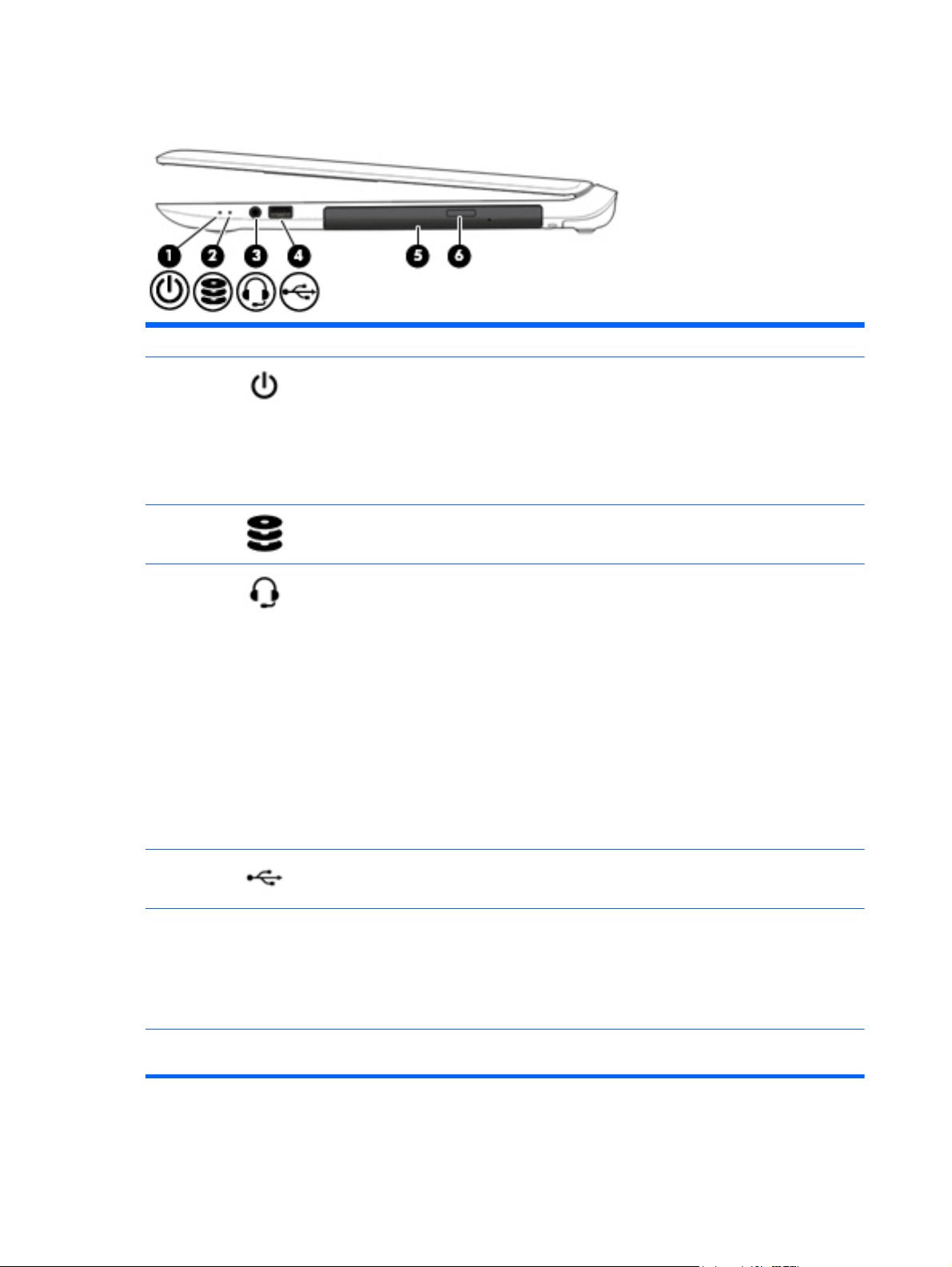
Right side
Component Description
(1)
(2)
(3)
Power light
Hard drive light Blinking white: The hard drive is being accessed.
Audio-out (headphone)/Audio-in
(microphone) jack
●
On: The computer is on.
●
Blinking: The computer is in the Sleep state, a powersaving state. The computer shuts off power to the
display and other components.
●
Off: The computer is off or in Hibernation.
Hibernation is a power-saving state that uses the
least amount of power.
Connects optional powered stereo speakers, headphones,
earbuds, a headset, or a television audio cable. Also
connects an optional headset microphone. This jack does
not support optional microphone-only devices.
WARNING! To reduce the risk of personal injury, adjust
the volume before putting on headphones, earbuds, or a
headset. For additional safety information, see the
Regulatory, Safety, and Environmental Notices. To access
this guide, from the Start screen, type support, and then
select the HP Support Assistant app.
NOTE: When a device is connected to the jack, the
computer speakers are disabled.
NOTE: Be sure that the device cable has a 4-conductor
connector that supports both audio-out (headphone) and
audio-in (microphone).
USB 2.0 port Connects an optional USB device, such as a keyboard,
(4)
(5) Optical drive (select models only) Depending on your computer model, reads an optical disc
(6) Optical drive eject button (select models
only)
6 Chapter 2 External component identification
mouse, external drive, printer, scanner or USB hub.
or reads and writes to an optical disc.
NOTE: For disc compatibility information, navigate to the
Help and Support web page. Follow the web page
instructions to select your computer model. Select
Support & Drivers, and then select Product Information.
Releases the optical drive disc tray.
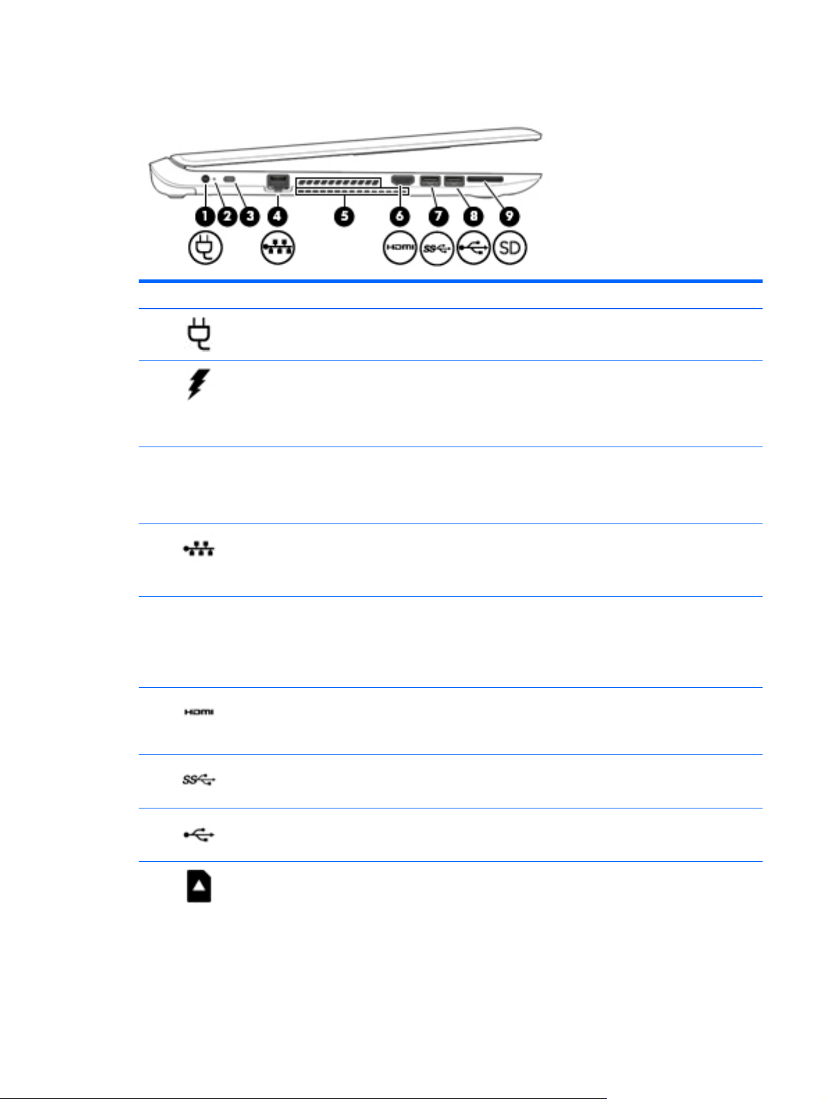
Left side
Component Description
(1)
(2)
Power connector Connects an AC adapter.
●
White: AC in and battery is full charged. (100%)
●
Amber: The computer is connected to external
power and the battery is charging.
AC adapter light
●
Off: The computer is using battery power.
(3)
(4)
(5)
(6)
(7)
(8)
Attaches an optional security cable to the computer.
NOTE: The security cable is designed to act as a
Security cable slot
RJ-45 (network) jack/status lights Connects a network cable.
Vents (2) Enables airflow to cool internal components.
HDMI port Connects an optional video or audio device, such as
USB 3.0 port Connects an optional USB device, such as a
USB 2.0 port
deterrent, but it may not prevent the computer
from being mishandled or stolen.
●
White: The network is connected.
●
Amber: Activity is occurring on the network.
NOTE: The computer fan starts up automatically
to cool internal components and prevent
overheating. It is normal for the internal fan to cycle
on and off during routine operation.
a high-definition television, any compatible digital
or audio component, or a high-speed HighDefinition Multimedia Interface (HDMI) device.
keyboard, mouse, external drive, printer, scanner or
USB hub.
Connects an optional USB device, such as a
keyboard, mouse, external drive, printer, scanner or
USB hub.
(9)
Memory card reader Reads optional memory cards that enable you to
store, manage, share or access information.
To insert a card:
▲
Hold the card label-side up, with connectors
facing the slot, insert the card into the slot,
and then push in on the card until it is firmly
seated.
Left side 7

Display
Component Description
To remove a card:
▲
Press in on the card it until it pops out.
Component Description
(1) Internal display switch Turns off the display and initiates Sleep if the display is closed while
the power is on.
NOTE: The internal display switch is not visible from the outside of
the computer.
(2) WLAN antennas* Send and receive wireless signals to communicate with wireless local
area networks (WLANs).
(3) Webcam light On: The webcam is in use.
(4) Webcam Records video and captures photographs. Some models allow you to
video conference and chat online using streaming video.
▲
From the Start screen, type camera, and then select Camera
from the list of applications.
(5) Internal microphone Records sound.
*The antennas are not visible from the outside of the computer. For optimal transmission, keep the areas immediately around the
antennas free from obstructions. For wireless regulatory notices, see the section of the Regulatory, Safety, and Environmental Notices
that applies to your country or region.
To access this document:
From the Start screen, type support, and then select the HP Support Assistant app.
8 Chapter 2 External component identification

Component Description
‒ or –
From the Windows desktop, click the question mark icon in the notification area, at the far right of the taskbar.
Display 9
Top
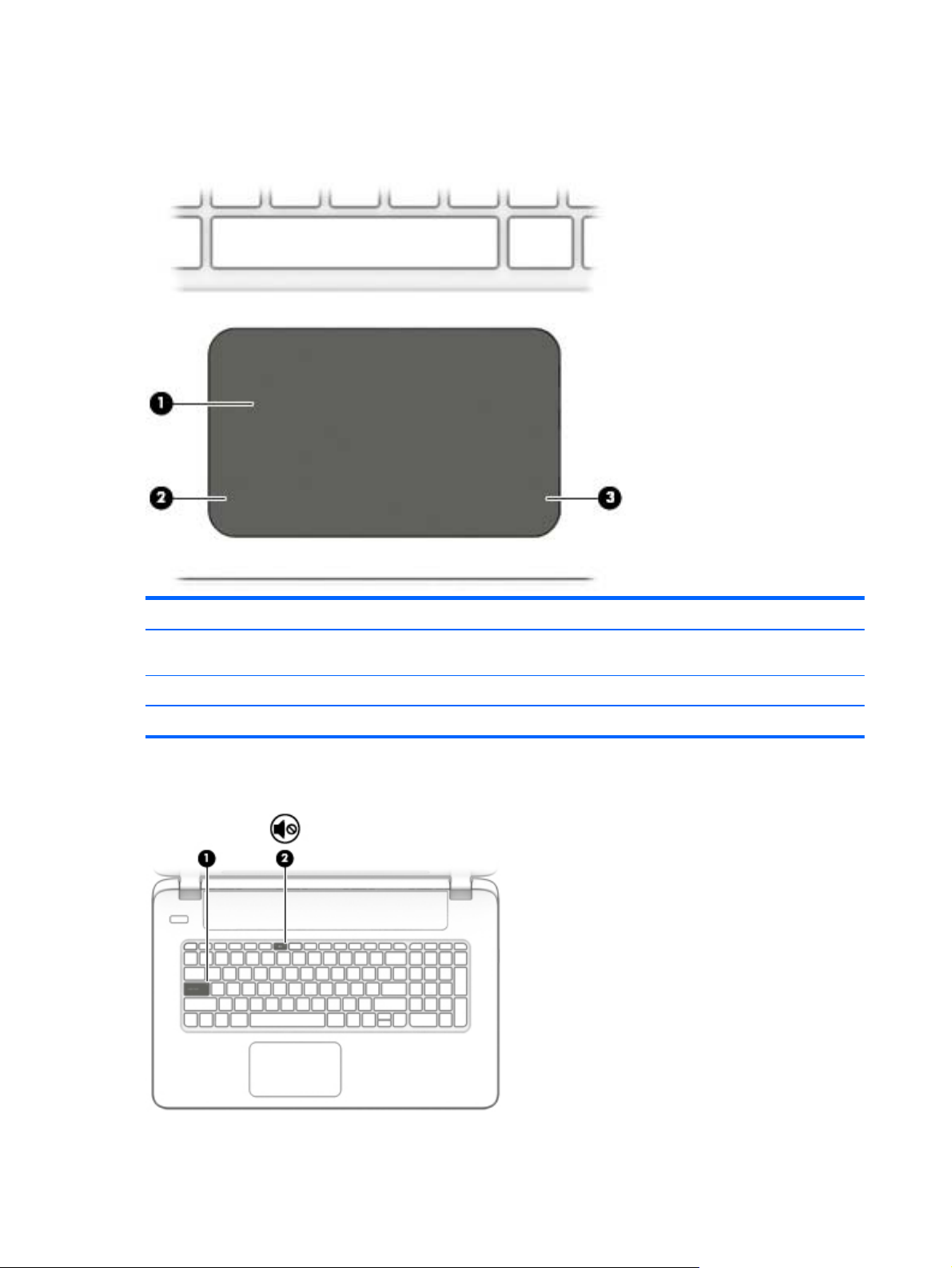
TouchPad
Lights
Component Description
(1) TouchPad zone Reads your finger gestures to move the pointer or activate
items on the screen.
(2) Left TouchPad button Functions like the left button on an external mouse.
(3) Right TouchPad button Functions like the right button on an external mouse.
10 Chapter 2 External component identification
Component Description
(1) Caps lock light On: Caps lock is on, which switches the keys to all capital letters.
(2)
Mute light
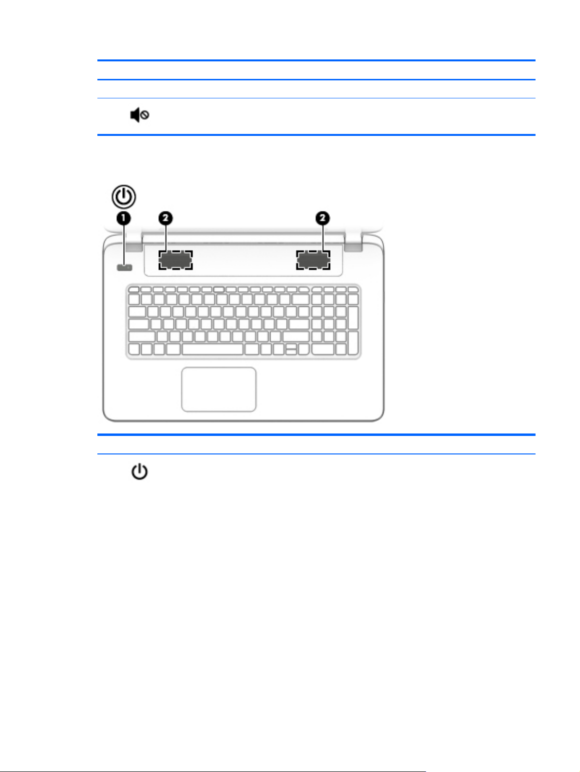
Buttons and speakers (select models only)
●
Amber: Computer sound is off.
●
Off: Computer sound is on.
Component Description
(1)
Power button
●
When the computer is off, press the button to turn on the
computer.
●
When the computer is on, press the button briefly to
initiate Sleep.
●
When the computer is in the Sleep state, press the button
briefly to exit Sleep.
●
When the computer is in Hibernation, press the button
briefly to exit Hibernation.
CAUTION: Pressing and holding down the power button will
result in the loss of unsaved information.
If the computer has stopped responding and Windows shutdown
procedures are ineffective, press and hold the power button
down for at least 5 seconds to turn off the computer.
To learn more about your power settings, see your power
options.
▲
From the Start screen, type power, select Power and
sleep settings, and then select Power and sleep from the
list of applications.
Top 11

Component Description
‒ or –
From the Windows desktop, right-click the Start button,
and then select Power Options.
(2) Speakers Produce sound.
12 Chapter 2 External component identification
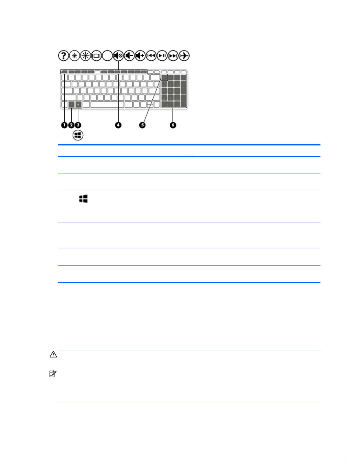
Keys
Component Description
(1) esc key Displays system information when pressed in combination with
the fn key.
(2) fn key Executes frequently used system functions when pressed in
combination with the esc key, action keys, or the spacebar.
(3)
(4) Action keys Execute frequently used system functions.
(5) num lock key Alternates between the navigational and numeric functions on
(6) Integrated numeric keypad When num lock is on, it can be used like an external numeric
Windows key Returns you to the Start screen from an open app or the
Using the action keys
Depending on the model, your computer may have the function key features as described in this table.
An action key performs an assigned function. The icon on each of the action keys illustrates the assigned
function for that key.
To use an action key function, press and hold the key.
CAUTION: Use extreme care when making changes in Setup Utility (BIOS). Errors can prevent the computer
from operating properly.
Windows desktop.
NOTE: Pressing the Windows key again will return you to the
previous screen.
NOTE: On select models, the f5 action key turns the radiance
backlight keyboard feature off or on.
the integrated numeric keypad.
keypad.
NOTE: The action key feature is enabled at the factory. You can disable this feature in Setup Utility (BIOS).
Refer to Help and Support for additional information.
After you have disabled the action key feature, you can still perform each function by pressing the fn key in
combination with the appropriate action key.
Top 13
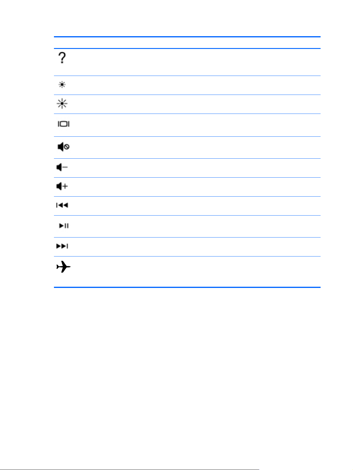
Icon Description
Opens Help and Support, which provides tutorials, information about the Windows operating system and
your computer, answers to questions, and updates to your computer.
Help and Support also provides automated troubleshooting tools and access to support.
Decreases the screen brightness incrementally as long as you hold down the key.
Increases the screen brightness incrementally as long as you hold down the key.
Switches the screen image between display devices connected to the system. For example, if a monitor is
connected to the computer, repeatedly pressing this key alternates the screen image from the computer
display to the monitor display to a simultaneous display on both the computer and the monitor.
Mutes or restores speaker sound.
Decreases speaker volume incrementally while you hold down the key.
Increases speaker volume incrementally while you hold down the key.
Plays the previous track of an audio CD or the previous section of a DVD or a BD.
Begins, pauses, or resumes playback of an audio CD, a DVD, or a BD.
Plays the next track of an audio CD or the next section of a DVD or a BD.
Turns the airplane mode and wireless feature on or off.
NOTE: The airplane mode key is also referred to as the wireless button.
NOTE: A wireless network must be set up before a wireless connection is possible.
14 Chapter 2 External component identification
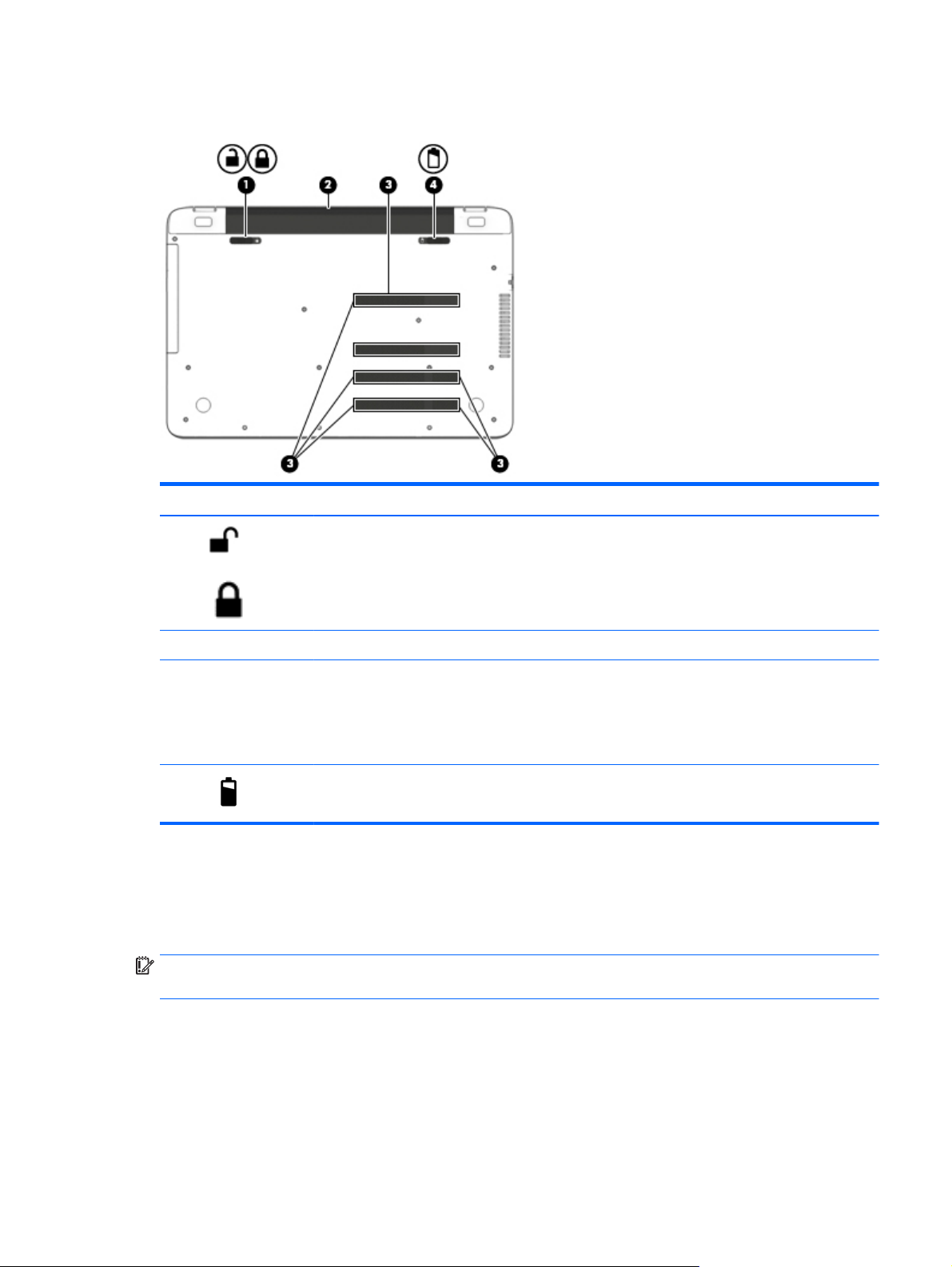
Bottom
Component Description
Labels
(1)
(2) Battery bay Holds the battery.
(3) Vents (6) Enable airflow to cool internal components.
(4)
Battery lock Locks the battery in the battery bay.
NOTE: The computer fan starts up automatically to cool
internal components and prevent overheating. It is normal
for the internal fan to cycle on and off during routine
operation.
Battery release latch Releases the battery.
The labels affixed to the computer provide information you may need when you troubleshoot system
problems or travel internationally with the computer.
IMPORTANT: Check the following locations for the labels described in this section: the bottom of the
computer, inside the battery bay, or on the back of the display.
●
Service label—Provides important information to identify your computer. When contacting support,
you will probably be asked for the serial number, and possibly for the product number or the model
number. Locate these numbers before you contact support.
Your service label will resemble one of the examples shown below. Refer to the illustration that most
closely matches the service label on your computer.
Bottom 15
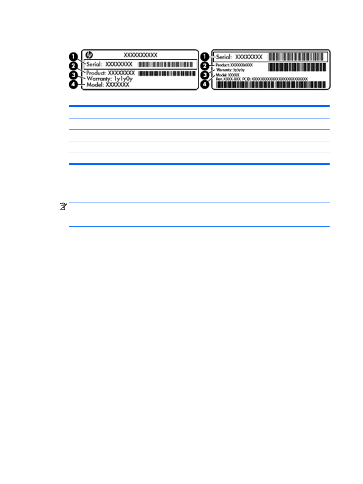
Component
(1) Serial number
(2) Product number
(3) Warranty period
(4) Model number (select models only)
●
Microsoft® Certificate of Authenticity label (select models only prior to Windows 8)—Contains the
Windows Product Key. You may need the Product Key to update or troubleshoot the operating system.
HP platforms with Windows 8 or Windows 8.x preinstalled do not have the physical label. Instead a
Digital Product Key is electronically installed.
NOTE: The Digital Product Key is automatically recognized and activated by Microsoft operating
systems when a Windows 8 or Windows 8.x operating system is reinstalled using HP-approved recovery
methods.
●
Regulatory label(s)—Provide(s) regulatory information about the computer.
●
Wireless certification label(s)—Provide(s) information about optional wireless devices and the approval
markings for the countries or regions in which the devices have been approved for use.
16 Chapter 2 External component identification

3 Illustrated parts catalog
Computer major components
NOTE: HP continually improves and changes product parts. For complete and current information on
supported parts for your computer, go to
follow the on-screen instructions.
http://partsurfer.hp.com, select your country or region, and then
Computer major components 17
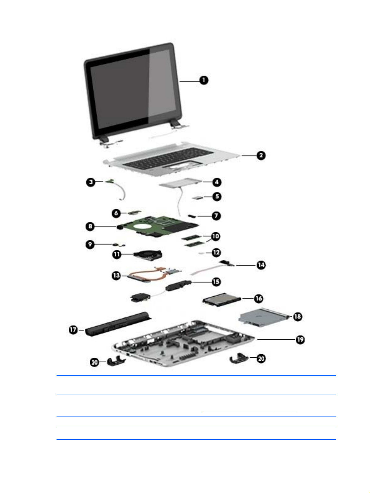
Item Component Spare part
(1) Display assembly [17.3 in 43.9 cm] HD+ non-touch screen
NOTE: For display assembly spare part information, see
WLED Brightview HD+ 810319-001
(2) Top cover/keyboard (the keyboard and top cover are spared together)
18 Chapter 3 Illustrated parts catalog
number
Display assembly subcomponents on page 21.

Item Component Spare part
For use in Belgium 809983-A41
For use in the Czech Republic and Slovakia 809983-FL1
For use in Denmark, Finland, and Norway 809983-DH1
For use in French Canada 809983-DB1
For use in France 809983-051
For use in Germany 809983-041
For use in Greece 809983-151
For use in Hungary 809983-211
For use in the Netherlands 809983-B31
For use in Portugal 809983-131
For use in Russia 809983-251
For use in Saudi Arabia 809983-171
For use in Spain 809983-071
For use in Slovenia 809983-BA1
For use in Switzerland 809983-BG1
number
For use in the United Kingdom 809983-031
For use in the United States 809983-001
(3) Power button board (includes cable) 812177-001
(4) Touchpad (includes bracket) 810602-001
(5) WLAN module:
Realtek RTL8188EE 802.11b/g/n 1x1 Wi-Fi Adapter 709848-005
Realtek RTL8723BE 802.11b/g/n 1x1 Wi-Fi + BT4.0 Combo Adapter 753077-005
(6) Battery board 763710-001
(7) USB board (includes cable) 767120-001
(8) System board (includes replacement thermal materials):
All system boards use the following part numbers:
xxxxxx-001: Without the Windows operating system
xxxxxx-501: Windows 8.1 Standard
AMD A10-7300 A76M (1.9 GHz, up to 3.2 GHz, 2 MB L2), quad core 20 W, Max DDR3L-1600 809985-xx1
AMD A8-7050 (2.2 GHz up to 3.0 GHz, 2 MB L2), dual core 15 W, Max DDR3L-1600 809986-xx1
AMD A6-6310 (1.8 GHz up to 2.4 GHz, 2 MB L2), quad core 15 W, 1600 MHz DDR3L 809987-xx1
AMD E1-6010 (1.35 GHz up to 1 MB L2), dual core 10 W, Max DDR3L-1333 809988-xx1
(9) Power connector (includes cable) 763699-001
(10) Memory module (PC3L, 12800, DDR3L-160 ):
Computer major components 19

Item Component Spare part
8 GB 693374-005
4 GB 691740-005
2 GB 691739-005
(11) Fan 765788-001
(12) RTC battery 697917-001
(13) Heat sink assembly (includes replacement thermal materials):
For use only on computer models equipped with AMD processors and UMA graphics 764080-001
(14) Display Cable 765785-001
(15) Speaker kit (includes left and right speakers and cable) 763717-001
(16) Hard drive (does not include bracket):
500 GB 5400 rpm 7 mm/ 9.5 mm 778186-005
750 GB, 5400 rpm, 9.5 mm 778190-005
1 TB, 5400 rpm SATA 2.5 in 778192-005
Hard drive kit (includes bracket and cable) 773501-001
(17) Battery (4-cell, 41-Whr, 2.8-Ah Li-ion) 756743-001
number
(18) Optical drive, SATA DVD+/-RW DL SuperMulti (includes optical drive hardware kit with optical drive
bezel and bracket):
Optical drive, External DVDRW Drive (includes optical drive hardware kit with optical drive bezel and
bracket):
(19) Bottom cover 809981-001
(20) Base enclosure hinge caps (left and right) 765789-001
809984-001
747080-001
20 Chapter 3 Illustrated parts catalog
 Loading...