

Page 1

HP 17 Notebook
AMD models 17-p000 –17-p199
Maintenance and Service Guide
Page 2

© Copyright 2015, 2016 HP Development
Company, L.P.
AMD and Radeon are trademarks of Advanced
Micro Devices, Inc. Bluetooth is a trademark
owned by its proprietor and used by HewlettPackard Company under license. Microsoft and
Windows are U.S. registered trademarks of the
Microsoft group of companies. SD Logo is a
trademark of its proprietor.
For DTS patents, see http://patents.dts.com.
Manufactured under license from DTS
Licensing Limited. DTS, the Symbol, & DTS and
the Symbol together are registered
trademarks, and DTS Studio Sound is a
trademark of DTS, Inc. © DTS, Inc. All Rights
Reserved .
The information contained herein is subject to
change without notice. The only warranties for
HP products and services are set forth in the
express warranty statements accompanying
such products and services. Nothing herein
should be construed as constituting an
additional warranty. HP shall not be liable for
technical or editorial errors or omissions
contained herein.
Product notice
This guide describes features that are common
to most models. Some features may not be
available on your computer.
Not all features are available on all editions of
Windows. This computer may require upgraded
and/or separately purchased hardware,
drivers, and/or software to take full advantage
of Windows functionality. See
http://www.microsoft.com for details.
Third Edition: February 2016
Second Edition: September 2015
First Edition: April 2015
Document Part Number: 811417-003
Page 3

Safety warning notice
WARNING! To reduce the possibility of heat-related injuries or of overheating the device, do not place the
device directly on your lap or obstruct the device air vents. Use the device only on a hard, flat surface. Do not
allow another hard surface, such as an adjoining optional printer, or a soft surface, such as pillows or rugs or
clothing, to block airflow. Also, do not allow the AC adapter to contact the skin or a soft surface, such as
pillows or rugs or clothing, during operation. The device and the AC adapter comply with the user-accessible
surface temperature limits defined by the International Standard for Safety of Information Technology
Equipment (IEC 60950).
iii
Page 4

iv Safety warning notice
Page 5

Table of contents
1 Product description ....................................................................................................................................... 1
2 External component identification ................................................................................................................. 5
Right side ............................................................................................................................................................... 6
Left side ................................................................................................................................................................. 7
Display ................................................................................................................................................................... 8
Top ......................................................................................................................................................................... 9
TouchPad ............................................................................................................................................. 9
Lights ................................................................................................................................................... 9
Buttons and speakers (select products only) ................................................................................... 10
Keys ................................................................................................................................................... 11
Bottom ................................................................................................................................................................. 12
3 Illustrated parts catalog .............................................................................................................................. 13
Computer major components ............................................................................................................................. 13
Display assembly subcomponents ..................................................................................................................... 17
Mass storage devices .......................................................................................................................................... 18
Miscellaneous parts ............................................................................................................................................. 18
4 Removal and replacement procedures preliminary requirements .................................................................... 21
Tools required ...................................................................................................................................................... 21
Service considerations ........................................................................................................................................ 21
Plastic parts ....................................................................................................................................... 21
Cables and connectors ...................................................................................................................... 21
Drive handling ................................................................................................................................... 22
Grounding guidelines ........................................................................................................................................... 22
Electrostatic discharge damage ....................................................................................................... 22
Packaging and transporting guidelines ......................................................................... 23
Workstation guidelines ................................................................................ 23
5 Removal and replacement procedures for Customer Self-Repair parts ............................................................. 25
Component replacement procedures ................................................................................................................. 25
Battery ............................................................................................................................................... 26
Optical drive ...................................................................................................................................... 27
v
Page 6

6 Removal and replacement procedures for Authorized Service Provider parts ................................................... 29
Component replacement procedures ................................................................................................................. 29
Base enclosure .................................................................................................................................. 30
Display panel ..................................................................................................................................... 34
WLAN module .................................................................................................................................... 42
TouchPad button board .................................................................................................................... 44
Battery Board (select models only) .................................................................................................. 45
Optical drive connector ..................................................................................................................... 45
USB board .......................................................................................................................................... 47
Hard drive .......................................................................................................................................... 48
System board .................................................................................................................................... 50
Speakers ............................................................................................................................................ 53
Memory modules .............................................................................................................................. 54
RTC battery ........................................................................................................................................ 55
Power connector ............................................................................................................................... 56
Fan ..................................................................................................................................................... 57
Heat sink ............................................................................................................................................ 58
Power button board .......................................................................................................................... 60
7 Computer Setup (BIOS), TPM, and HP Sure Start – Windows 10 ........................................................................ 61
Using Computer Setup ......................................................................................................................................... 61
Starting Computer Setup .................................................................................................................. 61
Navigating and selecting in Computer Setup ................................................................................... 62
Restoring factory settings in Computer Setup ................................................................................. 62
Updating the BIOS ............................................................................................................................. 63
Determining the BIOS ..................................................................................................... 63
Downloading a BIOS update ........................................................................................... 63
Changing the boot order using the f9 prompt .................................................................................. 64
TPM BIOS settings (select products only) ........................................................................................................... 65
Using HP Sure Start (select products only) ......................................................................................................... 65
8 Using Setup Utility (BIOS) in Windows 8.1 ...................................................................................................... 67
Starting Setup Utility (BIOS) ................................................................................................................................ 67
Updating Setup Utility (BIOS) .............................................................................................................................. 67
Determining the BIOS version ........................................................................................................... 67
Downloading a BIOS update .............................................................................................................. 68
9 HP PC Hardware Diagnostics (UEFI) – Windows 10 ........................................................................................... 69
Downloading HP PC Hardware Diagnostics (UEFI) to a USB device .................................................................... 70
vi
Page 7

10 Using HP PC Hardware Diagnostics (UEFI) in Windows 8.1 .............................................................................. 71
Downloading HP PC Hardware Diagnostics (UEFI) to a USB device .................................................................... 71
11 Specifications ........................................................................................................................................... 73
Computer specifications ...................................................................................................................................... 73
43.9-cm (17.3-in) display specifications ............................................................................................................ 74
Hard drive specifications ..................................................................................................................................... 75
DVD±RW SuperMulti DL Drive specifications ...................................................................................................... 76
12 Backup and recovery – Windows 10 ............................................................................................................. 77
Creating recovery media and backups ................................................................................................................ 77
Creating HP Recovery media (select products only) ........................................................................ 78
Using Windows Tools ........................................................................................................................................... 79
Restore and recovery .......................................................................................................................................... 79
Recovering using HP Recovery Manager .......................................................................................... 80
What you need to know before you get started ............................................................ 80
Using the HP Recovery partition (select products only) ................................................ 81
Using HP Recovery media to recover ............................................................................. 81
Changing the computer boot order ................................................................................ 82
Removing the HP Recovery partition (select products only) ......................................... 82
13 Backing up, restoring, and recovering in Windows 8.1 .................................................................................. 83
Creating recovery media and backups ................................................................................................................ 83
Creating HP Recovery media (select models only) ........................................................................... 83
Using Windows tools ........................................................................................................................................... 84
Restore and recovery .......................................................................................................................................... 84
Recovering using HP Recovery Manager .......................................................................................... 85
What you need to know before you get started ............................................................ 85
Using the HP Recovery partition (select models only) .................................................. 86
Using HP Recovery media to recover ............................................................................. 86
Changing the computer boot order ................................................................................ 86
Removing the HP Recovery partition (select models only) ........................................... 87
14 Power cord set requirements ...................................................................................................................... 89
Requirements for all countries ........................................................................................................................... 89
Requirements for specific countries and regions ............................................................................................... 90
15 Recycling .................................................................................................................................................. 93
Index ............................................................................................................................................................. 95
vii
Page 8

viii
Page 9

1 Product description
Category Description
Product name HP Notebook
Models 17-p000 –17-p099
Processors
Chipset AMD A76M FCH
Graphics Internal graphics:
Support HD Decode, DX11, and HDMI
Panel 16:9 Ultra Wide Aspect Ratio (17.3 in 43.9 cm), HD+WLED, SVA, BrightView, 1366×768 display, 6.0 mm; typical
Memory Two SODIMM slots - NON customer accessible / upgradeable
●
AMD A10-7300 (1.9 GHz, up to 3.2, GHz, 2 MB L2), quad core 20 W, Max DDR3L-1600
●
AMD A8-7050 (2.2 GHz up to 3.0 GHz, 2 MB L2), dual core 15 W, Max DDR3L-1600
●
AMD A6-6310 (1.8 GHz up to 2.4 GHz, 2 MB L2), quad core 15 W, 1600 MHz DDR3L
●
AMD E1-6010 (1.35 GHz up to 1 MB L2), dual core 10 W, Max DDR3L-1333
AMD Integrated SOC FCH
AMD Radeon™ R6 Graphic
AMD Radeon™ R5 Graphics
AMD Radeon™ R4 Graphics
AMD Radeon™ R2 Graphics
brightness: 220 nits
Supports LVDS (co-layout with eDP1.2 PRS)
DDR3L-1600 Dual Channel Support
DDR3L-16009 Single Channel Support
DDR3L-1333 Single Channel Support (DDR3L-1600 downgrade to DDR3L-1333)
Supports up to 8 GB of system RAM in the following configurations:
●
2048-MB total system memory (2048×1)
●
4096-MB total system memory (4096×1)
●
6144-MB total system memory (4096×1) + (2048×1)
●
8192-MB total system memory (8192×1)
Hard drives Supports 2.5 in (6.35 cm) SATA hard drives in 9.5 mm (.37 in) and 7.0 mm (.28 in) thicknesses
Single HDD configurations:
●
500-GB, 5400-rpm, 9.5-mm or 7.0-mm
●
750-GB, 5400-rpm, 9.5-mm
●
1-TB, 5400-rpm, 9.5-mm
Optical drive Fixed, serial SATA, 9.5-mm tray load
1
Page 10

Category Description
DVD+/-RW Double-Layer SuperMulti
Supports zero power optical drive
Supports M-disc
Audio/video HP Webcam VGA camera (USB 2.0 fixed, no tilt, with activity LED, 640 x 480 by 24 frames per second)
Dual speakers
Enable HP Noise Cancellation
DTS™ Sound
Ethernet Integrated 10/100 network interface card (NIC)
Wireless Compatible with Miracast-certified devices
Integrated Wireless options with single antenna (HMC/PCIe):
●
Realtek RTL8723BE 802.11b/g/n 1x1 Wi-Fi + BT4.0 Combo Adapter
●
Broadcom BCM43142 802.11 b/g/n 1x1 Wi-Fi + BT4.0 M.2 Combo Adapter
●
Realtek RTL8188EE 802.11b/g/n 1x1 Wi-Fi Adapter
●
Qualcomm Atheros AR9485 802.11 bgn 1x1 Wi-Fi Adapter
Internal card
expansion
External
media card
Ports HDMI version 1.4 supporting up to 1920 ×1080 @ 60Hz
Keyboard/
pointing
devices
Power
requirements
One half-size mini-card slot for WLAN
HP Multi-Format Digital Media Card Reader
Support SD/SDHC/SDXC
Push-Push Insertion/Removal
Hot Plug/unplug and auto detect for correct output to wide-aspect vs. standard aspect video
RJ-45
USB 3.0 (1 on left side)
USB 2.0 (1 on left side, one on right side)
AC Smart Pin adapter plug (4.5 mm barrel)
Headphone/Microphone combo jack
Full size standard textured island-style keyboard with numeric keypad
ClickPad with multi-touch gestures, with image sensor
Taps enabled by default
Support Modern Trackpad Gestures
Battery:
4-cell, 41-Whr, 2.8Ah, li-ion battery
Battery life enhancement
4 hr AMD for use with ULV APU (BGA, A10/A8)
5.75 hr AMD for use with APU (BGA, A8 A6/E1))
Supports fast charge
AC adapters:
2 Chapter 1 Product description
Page 11

Category Description
AC Adapter 45-W Smart nPFC, 3 pin, RC 4.5mm connector (models with UMA graphics only)
1 meter power cord
Security Security Lock
Operating
system
Serviceability End-user replaceable parts:
Preinstalled:
●
Windows 10
●
Windows 8.1
●
FreeDos 2.0
●
AC adapter
●
Battery
●
Optical drive
3
Page 12

4 Chapter 1 Product description
Page 13

2 External component identification
5
Page 14
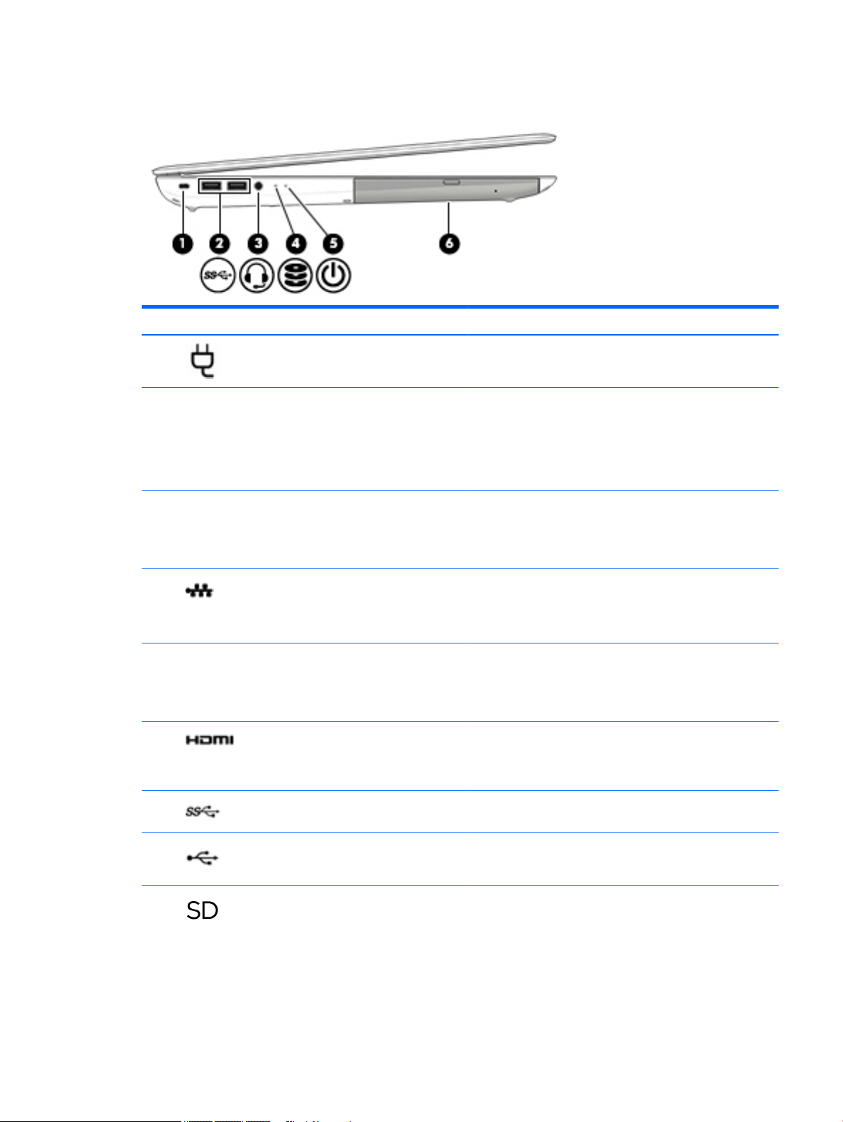
Right side
Component Description
(1) Power light
(2) Hard drive light
(3) Audio-out (headphone)/Audio-in (microphone)
jack
(4) USB 2.0 port Connects an optional USB device, such as a keyboard, mouse,
(5) Optical drive (select products only) Depending on your computer model, reads an optical disc or
●
On: The computer is on.
●
Blinking: The computer is in the Sleep state, a powersaving state. The computer shuts off power to the display
and other unneeded components.
●
Off: The computer is off or in Hibernation. Hibernation is a
power-saving state that uses the least amount of power.
●
Blinking white: The hard drive is being accessed.
Connects optional powered stereo speakers, headphones,
earbuds, a headset, or a television audio cable. Also connects an
optional headset microphone. This jack does not support
optional microphone-only devices.
WARNING! To reduce the risk of personal injury, adjust the
volume before putting on headphones, earbuds, or a headset.
For additional safety information, refer to the Regulatory,
Safety, and Environmental Notices.
NOTE: When a device is connected to the jack, the computer
speakers are disabled.
external drive, printer, scanner or USB hub.
reads and writes to an optical disc.
(6) Optical drive eject button (select products only) Releases the optical drive disc tray.
6 Chapter 2 External component identification
Page 15
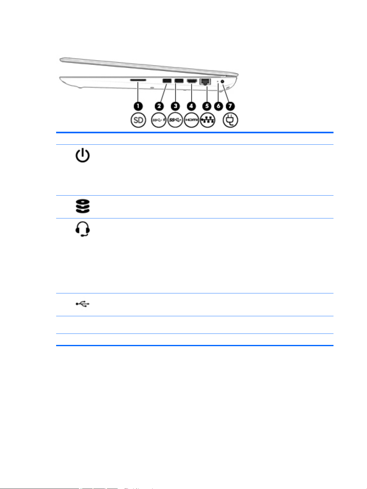
Left side
Component Description
(1) Power connector Connects an AC adapter.
(2) AC adapter/battery light
(3) Security cable slot Attaches an optional security cable to the computer.
(4) RJ-45 (network) jack/status lights Connects a network cable.
(5)
(6) HDMI port Connects an optional video or audio device, such as a high-
(7) USB 3.0 port Connects an optional USB device, such as a keyboard, mouse,
Vents (2) Enable airflow to cool internal components.
●
White: The AC adapter is connected and the battery is fully
charged.
●
Amber: The AC adapter is connected and the battery is
charging.
●
Off: The battery is not charging.
NOTE: The security cable is designed to act as a deterrent, but
it may not prevent the computer from being mishandled or
stolen.
●
White: The network is connected.
●
Amber: Activity is occurring on the network.
NOTE: The computer fan starts up automatically to cool
internal components and prevent overheating. It is normal for
the internal fan to cycle on and off during routine operation.
definition television, any compatible digital or audio
component, or a high-speed High-Definition Multimedia
Interface (HDMI) device.
external drive, printer, scanner or USB hub.
(8) USB 2.0 port Connects an optional USB device, such as a keyboard, mouse,
external drive, printer, scanner or USB hub.
(9) Memory card reader Reads optional memory cards that enable you to store, manage,
share, or access information.
To insert a card:
1. Hold the card label-side up, with connectors facing the
computer.
Left side 7
Page 16
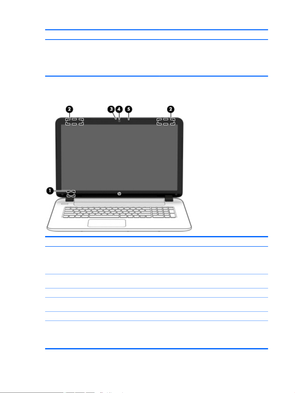
Display
Component Description
2. Insert the card into the memory card reader, and then
press in on the card until it is firmly seated.
To remove a card:
▲
Press in on the card, and then remove it from the memory
card reader.
Component Description
(1) Internal display switch Turns off the display and initiates Sleep if the display is closed while
(2) WLAN antennas* Send and receive wireless signals to communicate with wireless local
(3) Webcam light On: The webcam is in use.
(4) Webcam Records video and captures photographs. Some products allow you
(5) Internal microphone Records sound.
*The antennas are not visible from the outside of the computer. For optimal transmission, keep the areas immediately around the
antennas free from obstructions.
For wireless regulatory notices, see the section of the Regulatory, Safety, and Environmental Notices that applies to your country or
region.
8 Chapter 2 External component identification
the power is on.
NOTE: The internal display switch is not visible from the outside of
the computer.
area networks (WLANs).
to video conference and chat online using streaming video.
Page 17

Top
TouchPad
Component Description
(1) TouchPad zone Reads your finger gestures to move the pointer or activate
(2) Left TouchPad button Functions like the left button on an external mouse.
(3) Right TouchPad button Functions like the right button on an external mouse.
items on the screen.
Lights
Top 9
Page 18
Component Description
(1) Caps lock light On: Caps lock is on, which switches the key input to all capital
letters.
(2) Mute light
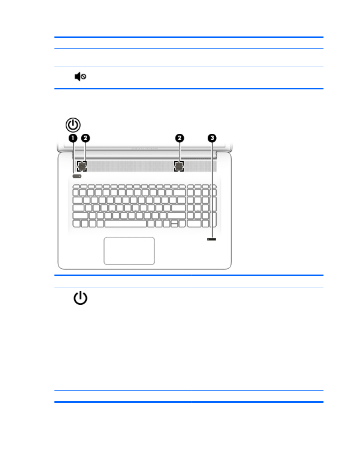
Buttons and speakers (select products only)
●
Amber: Computer sound is off.
●
Off: Computer sound is on.
Component Description
(1) Power button
(2) Speakers Produce sound.
10 Chapter 2 External component identification
●
When the computer is off, press the button to turn on the
computer.
●
When the computer is on, press the button briefly to
initiate Sleep.
●
When the computer is in the Sleep state, press the button
briefly to exit Sleep.
●
When the computer is in Hibernation, press the button
briefly to exit Hibernation.
CAUTION: Pressing and holding down the power button results
in the loss of unsaved information.
If the computer has stopped responding and Windows shutdown
procedures are ineffective, press and hold the power button
down for at least 5 seconds to turn off the computer.
Page 19
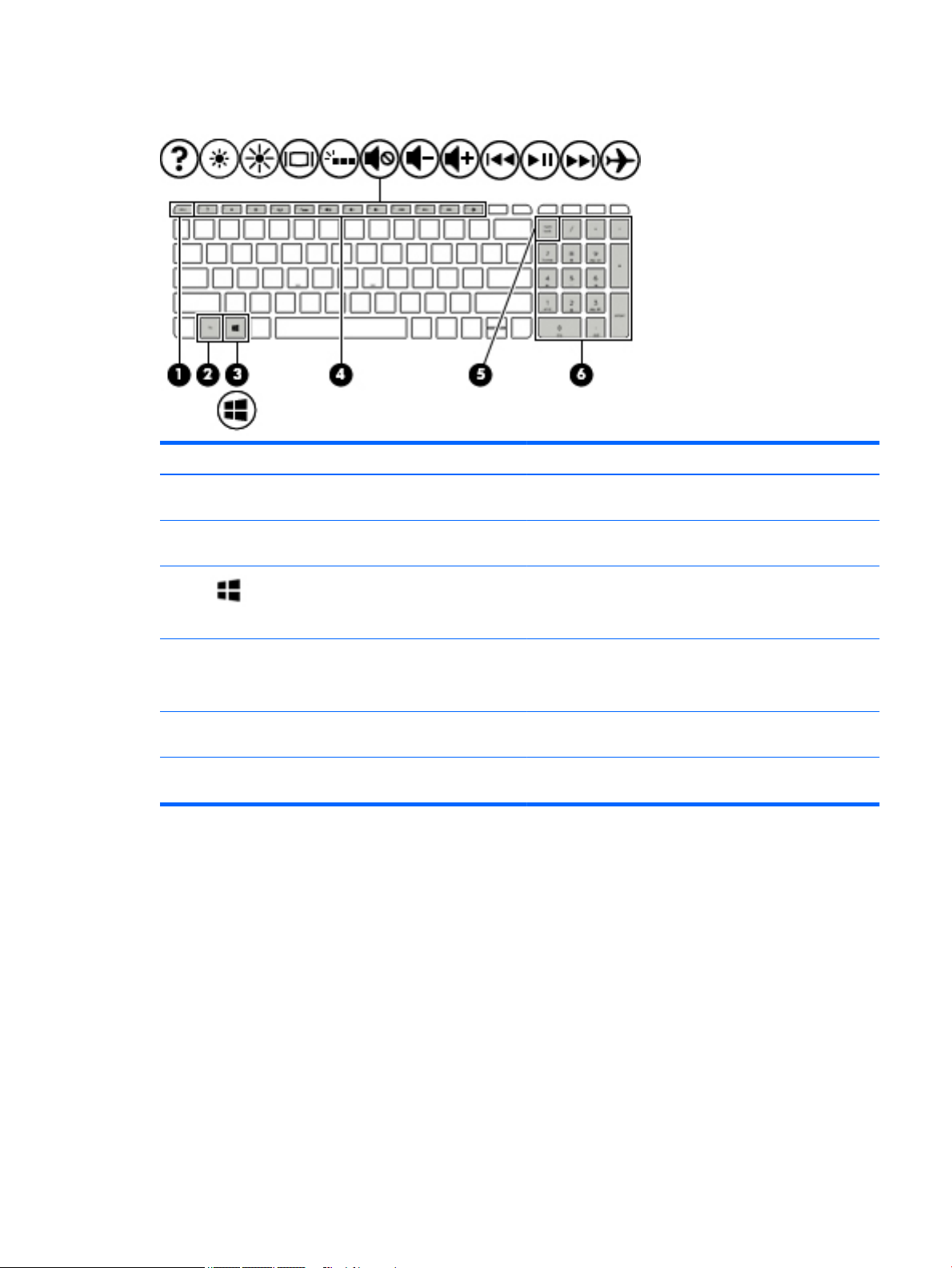
Keys
Component Description
(1) esc key Displays system information when pressed in combination with
the fn key.
(2) fn key Executes frequently used system functions when pressed in
combination with the esc key, action keys, or the spacebar.
(3) Windows key Opens the Start menu.
NOTE: Pressing the Windows key again will close the Start
menu.
(4) Action keys Execute frequently used system functions.
NOTE: On select products, the f5 action key turns the
backlight keyboard feature off or on.
(5) num lock key Alternates between the navigational and numeric functions on
the integrated numeric keypad.
(6) Integrated numeric keypad When num lock is on, the keypad can be used like an external
numeric keypad.
Top 11
Page 20
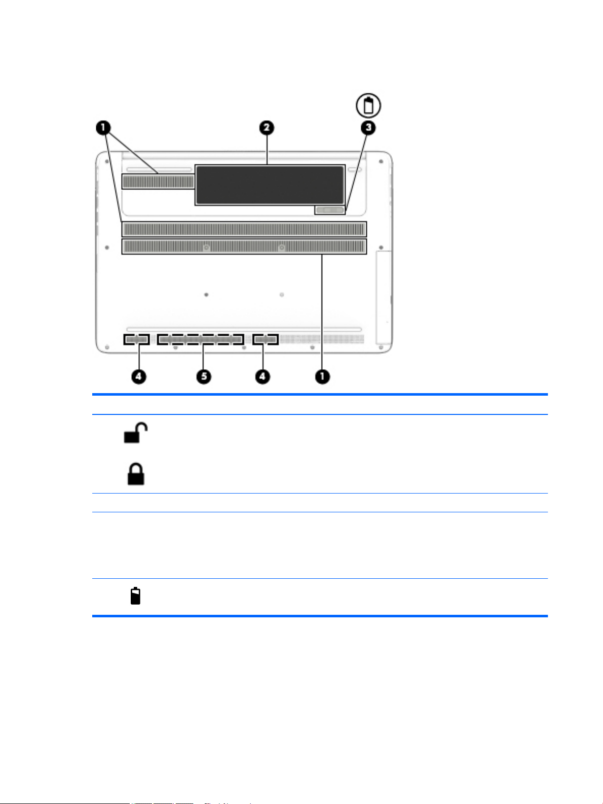
Bottom
Component Description
(1) Battery lock Locks the battery in the battery bay.
(2) Battery bay Holds the battery.
(3) Vents (6) Enable airflow to cool internal components.
NOTE: The computer fan starts up automatically to cool
internal components and prevent overheating. It is normal
for the internal fan to cycle on and off during routine
operation.
(4) Battery release latch Releases the battery.
12 Chapter 2 External component identification
Page 21

3 Illustrated parts catalog
Computer major components
NOTE: HP continually improves and changes product parts. For complete and current information on
supported parts for your computer, go to http://partsurfer.hp.com, select your country or region, and then
follow the on-screen instructions.
Computer major components 13
Page 22
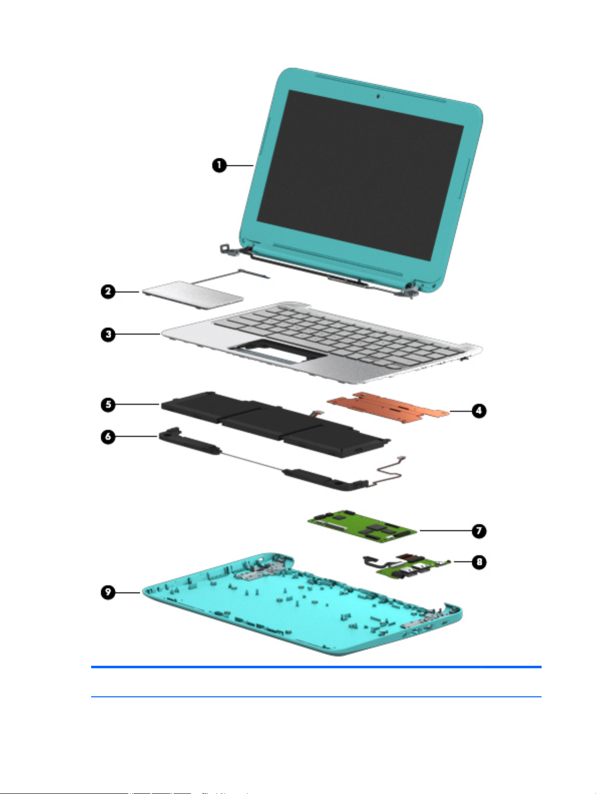
Item Component Spare part
(1) Display assembly [17.3 in 43.9 cm] HD+ non-touch screen
14 Chapter 3 Illustrated parts catalog
number
Page 23

Item Component Spare part
number
NOTE: For display assembly spare part information, see Display assembly subcomponents on page 17.
(2) Top cover/keyboard (the keyboard and top cover are spared together)
For use in Belgium 809983-A41
For use in the Czech Republic and Slovakia 809983-FL1
For use in Denmark, Finland, and Norway 809983-DH1
For use in French Canada 809983-DB1
For use in France 809983-051
For use in Germany 809983-041
For use in Greece 809983-151
For use in Hungary 809983-211
For use in the Netherlands 809983-B31
For use in Portugal 809983-131
For use in Russia 809983-251
For use in Saudi Arabia 809983-171
For use in Spain 809983-071
For use in Slovenia 809983-BA1
For use in Switzerland 809983-BG1
For use in the United Kingdom 809983-031
For use in the United States 809983-001
(3) Power button board (includes cable) 812177-001
(4) Touchpad (includes bracket) 810602-001
(5) WLAN module:
Realtek RTL8188EE 802.11b/g/n 1x1 Wi-Fi Adapter 709848-005
Realtek RTL8723BE 802.11b/g/n 1x1 Wi-Fi + BT4.0 Combo Adapter 753077-005
(6) Battery board 763710-001
(7) USB board (includes cable) 767120-001
(8) System board (includes replacement thermal materials):
All system boards use the following part numbers:
xxxxxx-001: Without the Windows operating system
xxxxxx-501: Windows 8.1 Standard
xxxxxx-601: Windows 10
AMD A10-7300 A76M (1.9 GHz, up to 3.2 GHz, 2 MB L2), quad core 20 W, Max DDR3L-1600 809985-xx1
AMD A8-7050 (2.2 GHz up to 3.0 GHz, 2 MB L2), dual core 15 W, Max DDR3L-1600 809986-xx1
AMD A6-6310 (1.8 GHz up to 2.4 GHz, 2 MB L2), quad core 15 W, 1600 MHz DDR3L 809987-xx1
Computer major components 15
Page 24

Item Component Spare part
number
AMD E1-6010 (1.35 GHz up to 1 MB L2), dual core 10 W, Max DDR3L-1333 809988-xx1
(9) Power connector (includes cable) 763699-001
(10) Memory module (PC3L, 12800, DDR3L-160 ):
8 GB 693374-005
4 GB 691740-005
2 GB 691739-005
(11) Fan 765788-001
(12) RTC battery 697917-001
(13) Heat sink assembly (includes replacement thermal materials):
For use only on computer models equipped with AMD processors and UMA graphics 764080-001
(14) Display Cable 765785-001
(15) Speaker kit (includes left and right speakers and cable) 763717-001
(16) Hard drive (does not include bracket):
For hard drive spare part details, see Mass storage devices on page 18.
(17) Battery (4-cell, 41-Whr, 2.8-Ah Li-ion) 756743-001
(18) Optical drive, SATA DVD+/-RW DL SuperMulti (includes optical drive hardware kit with optical drive
bezel and bracket):
For optical drive spare part details, see Mass storage devices on page 18.
(19) Bottom cover 809981-001
(20) Base enclosure hinge caps (left and right) 765789-001
16 Chapter 3 Illustrated parts catalog
Page 25
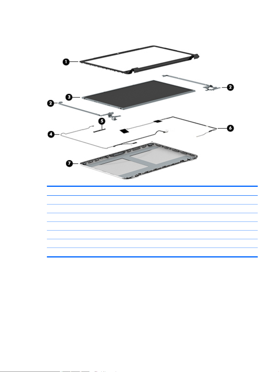
Display assembly subcomponents
Item Component Spare part number
(1) Display bezel (includes screw covers) 809982-001
(2) Hinges (left and right, includes screw covers) 763706-001
(3) Raw display panel (16:9 Ultra Wide Aspect Ratio [17.3 in, 43.9 cm ]; includes screw covers) 810319-001
(4) Display cable HD+ (includes screw covers) 765785-001
(5) Webcam/microphone module (with cables) 809989-001
(6) Antennas (includes wireless antenna cables and transceivers; includes screw covers) 763691-001
(7) Display enclosure: 809980-001
Display assembly subcomponents 17
Page 26
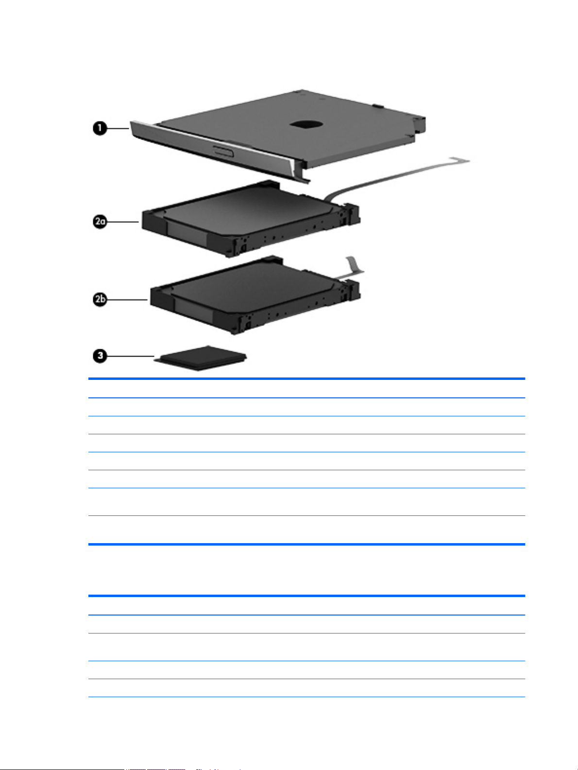
Mass storage devices
Item Component Spare part number
(1) Hard drive (does not include the hard drive rubber bracket, hard drive connector cable, or screws)
500 GB 5400 rpm 7 mm/ 9.5 mm SATA 2.5 in 778186-005
750 GB, 5400 rpm, 9.5 mm SATA 2.5 in 778190-005
1 TB, 5400 rpm 9.5 mm SATA 2.5 in 778192-005
Hard Drive Hardware Kit 773501-001
(2) Optical drive, SATA DVD+/-RW DL SuperMulti (includes optical drive hardware kit with
optical drive bezel and bracket):
Optical drive, External DVDRW Drive (includes optical drive hardware kit with optical drive
bezel and bracket):
Miscellaneous parts
Component
HP Smart AC adapter:
45-W non-PFC, non-slim HP Smart AC adapter (for use in all countries and regions except for the
People’s Republic of China and India)
Power cord (3-pin, black, 1.0-m):
809984-001
747080-001
Spare part number
741727-001
For use in Denmark 755530-081
18 Chapter 3 Illustrated parts catalog
Page 27

Component Spare part number
For use in Europe, the Middle East, and Africa 755530-021
For use in North America 755530-001
For use in Switzerland 755530-111
For use in the United Kingdom and Singapore 755530-031
Rubber Kit (includes front and rear feet) 763714-001
Screw Kit 765790-001
HDMI to VGA adapter 701943-001
Miscellaneous parts 19
Page 28

20 Chapter 3 Illustrated parts catalog
Page 29

4 Removal and replacement procedures
preliminary requirements
Tools required
You will need the following tools to complete the removal and replacement procedures:
●
Flat-bladed screwdriver
●
Magnetic screwdriver
●
Phillips P0 and P1 screwdrivers
Service considerations
The following sections include some of the considerations that you must keep in mind during disassembly
and assembly procedures.
NOTE: As you remove each subassembly from the computer, place the subassembly (and all accompanying
screws) away from the work area to prevent damage.
Plastic parts
CAUTION: Using excessive force during disassembly and reassembly can damage plastic parts. Use care
when handling the plastic parts. Apply pressure only at the points designated in the
maintenance instructions.
Cables and connectors
CAUTION: When servicing the computer, be sure that cables are placed in their proper locations during the
reassembly process. Improper cable placement can damage the computer.
Cables must be handled with extreme care to avoid damage. Apply only the tension required to unseat or
seat the cables during removal and insertion. Handle cables by the connector whenever possible. In all cases,
avoid bending, twisting, or tearing cables. Be sure that cables are routed in such a way that they cannot be
caught or snagged by parts being removed or replaced. Handle flex cables with extreme care; these cables
tear easily.
Tools required 21
Page 30

Drive handling
CAUTION: Drives are fragile components that must be handled with care. To prevent damage to the
computer, damage to a drive, or loss of information, observe these precautions:
Before removing or inserting a hard drive, shut down the computer. If you are unsure whether the computer
is off or in Hibernation, turn the computer on, and then shut it down through the operating system.
Before handling a drive, be sure that you are discharged of static electricity. While handling a drive, avoid
touching the connector.
Before removing a diskette drive or optical drive, be sure that a diskette or disc is not in the drive and be sure
that the optical drive tray is closed.
Handle drives on surfaces covered with at least one inch of shock-proof foam.
Avoid dropping drives from any height onto any surface.
After removing a hard drive, an optical drive, or a diskette drive, place it in a static-proof bag.
Avoid exposing an internal hard drive to products that have magnetic fields, such as monitors or speakers.
Avoid exposing a drive to temperature extremes or liquids.
If a drive must be mailed, place the drive in a bubble pack mailer or other suitable form of protective
packaging and label the package “FRAGILE.”
Grounding guidelines
Electrostatic discharge damage
Electronic components are sensitive to electrostatic discharge (ESD). Circuitry design and structure
determine the degree of sensitivity. Networks built into many integrated circuits provide some protection,
but in many cases, ESD contains enough power to alter device parameters or melt silicon junctions.
A discharge of static electricity from a finger or other conductor can destroy static-sensitive devices or
microcircuitry. Even if the spark is neither felt nor heard, damage may have occurred.
An electronic device exposed to ESD may not be affected at all and can work perfectly throughout a normal
cycle. Or the device may function normally for a while, then degrade in the internal layers, reducing its life
expectancy.
CAUTION: To prevent damage to the computer when you are removing or installing internal components,
observe these precautions:
Keep components in their electrostatic-safe containers until you are ready to install them.
Before touching an electronic component, discharge static electricity by using the guidelines described in this
section.
Avoid touching pins, leads, and circuitry. Handle electronic components as little as possible.
If you remove a component, place it in an electrostatic-safe container.
The following table shows how humidity affects the electrostatic voltage levels generated by
different activities.
CAUTION: A product can be degraded by as little as 700 V.
22 Chapter 4 Removal and replacement procedures preliminary requirements
Page 31

Relative humidity
Event 10% 40% 55%
Walking across carpet 35,000 V 15,000 V 7,500 V
Walking across vinyl floor 12,000 V 5,000 V 3,000 V
Motions of bench worker 6,000 V 800 V 400 V
Removing DIPS from plastic tube 2,000 V 700 V 400 V
Removing DIPS from vinyl tray 11,500 V 4,000 V 2,000 V
Removing DIPS from Styrofoam 14,500 V 5,000 V 3,500 V
Removing bubble pack from PCB 26,500 V 20,000 V 7,000 V
Packing PCBs in foam-lined box 21,000 V 11,000 V 5,000 V
Packaging and transporting guidelines
Follow these grounding guidelines when packaging and transporting equipment:
●
To avoid hand contact, transport products in static-safe tubes, bags, or boxes.
●
Protect ESD-sensitive parts and assemblies with conductive or approved containers or packaging.
Typical electrostatic voltage levels
●
Keep ESD-sensitive parts in their containers until the parts arrive at static-free workstations.
●
Place items on a grounded surface before removing items from their containers.
●
Always be properly grounded when touching a component or assembly.
●
Store reusable ESD-sensitive parts from assemblies in protective packaging or non-conductive foam.
●
Use transporters and conveyors made of antistatic belts and roller bushings. Be sure that mechanized
equipment used for moving materials is wired to ground and that proper materials are selected to avoid
static charging. When grounding is not possible, use an ionizer to dissipate electric charges.
Workstation guidelines
Follow these grounding workstation guidelines:
●
Cover the workstation with approved static-shielding material.
●
Use a wrist strap connected to a properly grounded work surface and use properly grounded tools and
equipment.
●
Use conductive field service tools, such as cutters, screwdrivers, and vacuums.
●
When fixtures must directly contact dissipative surfaces, use fixtures made only of staticsafe materials.
●
Keep the work area free of nonconductive materials, such as ordinary plastic assembly aids
and Styrofoam.
●
Handle ESD-sensitive components, parts, and assemblies by the case or PCM laminate. Handle these
items only at static-free workstations.
Grounding guidelines 23
Page 32

●
Avoid contact with pins, leads, or circuitry.
●
Turn off power and input signals before inserting or removing connectors or test equipment.
Equipment guidelines
Grounding equipment must include either a wrist strap or a foot strap at a grounded workstation.
●
When seated, wear a wrist strap connected to a grounded system. Wrist straps are flexible straps with a
minimum of one megohm ±10% resistance in the ground cords. To provide proper ground, wear a strap
snugly against the skin at all times. On grounded mats with banana-plug connectors, use alligator clips
to connect a wrist strap.
●
When standing, use foot straps and a grounded floor mat. Foot straps (heel, toe, or boot straps) can be
used at standing workstations and are compatible with most types of shoes or boots. On conductive
floors or dissipative floor mats, use foot straps on both feet with a minimum of one megohm resistance
between the operator and ground. To be effective, the conductive must be worn in contact with the
skin.
The following grounding equipment is recommended to prevent electrostatic damage:
●
Antistatic tape
●
Antistatic smocks, aprons, and sleeve protectors
●
Conductive bins and other assembly or soldering aids
●
Nonconductive foam
●
Conductive tabletop workstations with ground cords of one megohm resistance
●
Static-dissipative tables or floor mats with hard ties to the ground
●
Field service kits
●
Static awareness labels
●
Material-handling packages
●
Nonconductive plastic bags, tubes, or boxes
●
Metal tote boxes
●
Electrostatic voltage levels and protective materials
The following table lists the shielding protection provided by antistatic bags and floor mats.
Material Use Voltage protection level
Antistatic plastics Bags 1,500 V
Carbon-loaded plastic Floor mats 7,500 V
Metallized laminate Floor mats 5,000 V
24 Chapter 4 Removal and replacement procedures preliminary requirements
Page 33

5 Removal and replacement procedures for
Customer Self-Repair parts
NOTE: The Customer Self-Repair program is not available in all locations. Installing a part not supported by
the Customer Self-Repair program may void your warranty. Check your warranty to determine if Customer
Self-Repair is supported in your location.
Component replacement procedures
NOTE: HP continually improves and changes product parts. For complete and current information on
supported parts for your computer, go to http://partsurfer.hp.com, select your country or region, and then
follow the on-screen instructions.
NOTE: Please read and follow the procedures described here to access and replace Customer Self-Repair
parts successfully.
NOTE: Details about your computer, including model, serial number, product key, and length of warranty,
are on the service tag at the bottom of your computer. See Bottom on page 12 for details.
This chapter provides removal and replacement procedures for Customer Self-Repair parts.
There may be as many as five screws that must be removed, replaced, and/or loosened when servicing
Customer Self-Repair parts. Make special note of each screw size and location during removal
and replacement.
Component replacement procedures 25
Page 34

Battery
Description Spare part number
4-cell, 41 WHr 2.8 AH Li-ion battery 756743-001
Before removing the battery, follow these steps:
1. Shut down the computer. If you are unsure whether the computer is off or in Hibernation, turn
the computer on, and then shut it down through the operating system.
2. Disconnect all external devices connected to the computer.
3. Disconnect the power from the computer by first unplugging the power cord from the AC outlet and
then unplugging the AC adapter from the computer.
Remove the battery:
1. Turn the computer upside down on a flat surface.
2. With the battery bay toward you, slide the battery lock latch (1) to unlock the battery and then slide the
battery release latch (2) to release the battery.
NOTE: The battery release latch automatically returns to its original position.
3. Pivot the battery (3) upward and then remove it from the computer (4).
Reverse this procedure to install the battery.
26 Chapter 5 Removal and replacement procedures for Customer Self-Repair parts
Page 35

Optical drive
NOTE: The optical drive spare part kit includes the optical drive connector board and cable. The optical
drive connector board and cable are removed when removing the system board and not part of the customer
replacement procedure of the optical drive.
Description Spare part number
Optical drive, DVD+/-RW DL SuperMulti (includes optical drive hardware kit with optical drive bezel and
bracket):
Optical drive, External DVDRW Drive (includes optical drive hardware kit with optical drive bezel and
bracket):
809984-001
747080-001
Before removing the optical drive, follow these steps:
1. Shut down the computer. If you are unsure whether the computer is off or in Hibernation, turn
the computer on, and then shut it down through the operating system.
2. Disconnect all external devices connected to the computer.
3. Disconnect the power from the computer by first unplugging the power cord from the AC outlet and
then unplugging the AC adapter from the computer.
4. Remove the battery (see Battery on page 26).
Remove the optical drive:
1. Remove the screw (1) that secures the optical drive to the computer.
Component replacement procedures 27
Page 36

2. Use a flat tool to press on the optical drive bracket tab (2) to release the optical drive.
3. Remove the optical drive from the computer.
NOTE: The optical drive bracket is included with the optical drive.
Reverse this procedure to reassemble and install the optical drive.
28 Chapter 5 Removal and replacement procedures for Customer Self-Repair parts
Page 37

6 Removal and replacement procedures for
Authorized Service Provider parts
NOTE: HP continually improves and changes product parts. For complete and current information on
supported parts for your computer, go to http://partsurfer.hp.com, select your country or region, and then
follow the on-screen instructions.
CAUTION: Components described in this chapter should only be accessed by an authorized service provider.
Accessing these parts can damage the computer or void the warranty.
Component replacement procedures
NOTE: Details about your computer, including model, serial number, product key, and length of warranty,
are on the service tag at the bottom of your computer. See Bottom on page 12 for details.
This chapter provides removal and replacement procedures for Authorized Service Provider only parts.
There are as many as 83 screws that must be removed, replaced, and/or loosened when servicing Authorized
Service Provider only parts. Make special note of each screw size and location during removal
and replacement.
Component replacement procedures 29
Page 38

Base enclosure
Description Spare part number
Top cover with keyboard:
With full size textured island-style Keyboard. TouchPad and numeric keypad black for use in the United
States
With full size textured island-style Keyboard and numeric keypad black for use in the United Kingdom 809983-031
With full size textured island-style Keyboard and numeric keypad black for use in Germany 809983-041
With full size textured island-style Keyboard and numeric keypad black for use in France 809983-051
With full size textured island-style Keyboard and numeric keypad black for use in Spain 809983-071
With full size textured island-style Keyboard and numeric keypad black for use in Portugal 809983-131
With full size textured island-style Keyboard and numeric keypad black for use in Greece 809983-151
With full size textured island-style Keyboard and numeric keypad black for use in Saudi Arabia 809983-171
With full size textured island-style Keyboard and numeric keypad black for use in Hungary 809983-211
With full size textured island-style Keyboard and numeric keypad black for use in Russia 809983-251
With full size textured island-style Keyboard and numeric keypad black for use in Europe 809983-A41
With full size textured island-style Keyboard and numeric keypad black for use in the Netherlands 809983-B31
With full size textured island-style Keyboard and numeric keypad black for use in the Adriatics 809983-BA1
With full size textured island-style Keyboard and numeric keypad black for use in Switzerland 809983-BG1
With full size textured island-style Keyboard and numeric keypad black Canada 809983-DB1
With full size textured island-style Keyboard and numeric keypad black for use in Denmark, Finland, and
Norway
809983-001
809983-DH1
With full size textured island-style Keyboard and numeric keypad black for use in the Czech Republic
and Slovakia
Base enclosure 809981-001
Base enclosure caps 765789-001
809983-FL1
Before disassembling the computer, follow these steps:
1. Shut down the computer. If you are unsure whether the computer is off or in Hibernation, turn
the computer on, and then shut it down through the operating system.
2. Disconnect all external devices connected to the computer.
3. Disconnect the power from the computer by first unplugging the power cord from the AC outlet and
then unplugging the AC adapter from the computer.
4. Remove the battery (see Battery on page 26).
5. Remove the optical drive (see Optical drive on page 27).
Remove the base enclosure:
1. Turn the computer face down, and remove the rubber feet (1), the two screws (2) and lift the end caps
(3).
30 Chapter 6 Removal and replacement procedures for Authorized Service Provider parts
Page 39

2. Remove the ten Phillips screws.
Component replacement procedures 31
Page 40

3. Remove five screws (1) around the battery area, three broadhead screws (2) in the optical drive bay and
one screw (3) near the display hinge.
NOTE: Some models may have two screws in the optical drive bay (2).
4. Turn the computer right side up and carefully remove the top cover.
NOTE: Use a thin, non-conductive tool to lift the top cover.
5. Carefully disconnect the following cables:
32 Chapter 6 Removal and replacement procedures for Authorized Service Provider parts
Page 41

●
Power button cable (1)
●
Keyboard cable (2)
●
TouchPad cable (3)
Lift the top cover (4) to remove it from the computer.
Reverse this procedure to install the top cover and base enclosure.
Component replacement procedures 33
Page 42

Display panel
Component Spare part number
Display bezel (includes screw covers) 809982-001
Hinges (left and right, includes screw covers) 763706-001
Raw display panel (16:9 Ultra Wide Aspect Ratio [43.9-cm 17.3-in]; includes screw covers) 810319-001
Antennas (includes wireless antenna cables and transceivers; includes screw covers) 763691-001
Webcam/microphone module 809989-001
Display cable SXGA (includes screw covers) 765785-001
Display enclosure: 809980-001
Before removing the display panel, follow these steps:
1. Shut down the computer. If you are unsure whether the computer is off or in Hibernation, turn
the computer on, and then shut it down through the operating system.
2. Disconnect all external devices connected to the computer.
3. Disconnect the power from the computer by first unplugging the power cord from the AC outlet and
then unplugging the AC adapter from the computer.
4. Remove the battery (see Battery on page 26).
5. Remove the optical drive (see Optical drive on page 27).
6. Remove the top cover from the base enclosure (see Base enclosure on page 30).
Remove the display panel:
1. Open the computer.
2. Disengage the display cable (1) and disconnect the display connector (2) on the left side base of the
display panel.
34 Chapter 6 Removal and replacement procedures for Authorized Service Provider parts
Page 43

3. On the right side, disconnect the WLAN cable (3) and carefully remove the cable from the retaining tabs
(4).
Component replacement procedures 35
Page 44
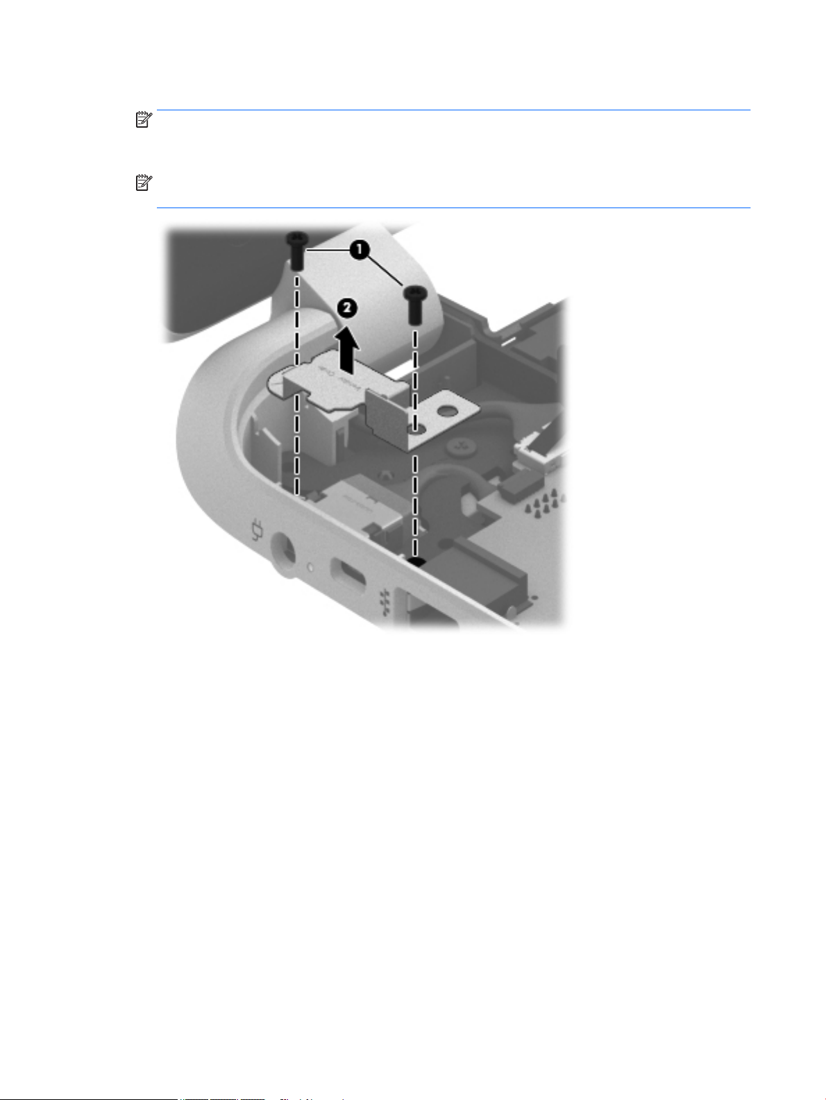
4. Remove the power connector cover by removing the two Phillips screws (1) and lifting the cover (2).
NOTE: The power connector cover has two screws, however, the screw on the left is removed during
the base enclosure and top cover removal process. Removing the cover is required for the display panel
removal.
NOTE: You will remove the power connector after you have removed the system board. This
procedure is to remove the power connector cover.
36 Chapter 6 Removal and replacement procedures for Authorized Service Provider parts
Page 45

5. Remove the six Phillips screws (1) on the left and one broadhead screw (2) on the right side base of the
display panel. Lift the panel up (3).
NOTE: Support the display panel as you are removing the screws.
6. Open the panel cover (1), swivel the display panel hinges (2) on both sides and then tilt up the display
panel hinge (3) to release it.
Component replacement procedures 37
Page 46

7. Loosen the edges of the back cover (1), (2), and (3) from all four sides of the display bezel and lift the
display panel (4).
NOTE: Use a sharp probe to pop the covers out to avoid scratching the bezel.
8. To remove the panel, remove the four Phillips screws (1) and any adhesive that secures the display
panel to the back cover and lift the display panel (2) carefully.
38 Chapter 6 Removal and replacement procedures for Authorized Service Provider parts
Page 47

9. If it is necessary to remove the display panel cable or access the webcamera and microphone, follow
these steps. With the display bezel upside down, disconnect the webcamera/microphone connectors (1)
and from the routing channel built into the back cover.
Carefully release the cable from the channel guides, the guides in the display hinge, and remove the
display panel cable (2). Lift the cable to remove it.
Component replacement procedures 39
Page 48

10. On select models, removing the panel also requires disengaging the panel from the back cover latch. To
disconnect the display panel, carefully rotate the display panel (1) to open it. Push upward on the
connection latch (2)panel and then disengage the panel from the back cover (3).
11. If it is necessary to replace the webcamera/microphone perform the following: Lift the module (1) from
the adhesive holding it in place on the display bezel and disconnect the module connector (2) if you
have not already done so when removing the display cable.
12. If it is necessary to replace the WLAN antenna cable, follow these procedures:
a. Position the display back cover face up.
40 Chapter 6 Removal and replacement procedures for Authorized Service Provider parts
Page 49

b. Remove the display brackets by removing the eight Phillips and broadhead screws (1) securing the
hinge brackets to the back cover, and then lift the brackets (2) to remove them.
c. Release the wireless antenna transceivers (1) from the display bezel. (The wireless antenna
transceivers are attached to the display bezel with double-sided tape.)
d. Remove the wireless antenna from the retaining channels (2), and lift the antenna (3)
Reverse this procedure to install the display panel.
Component replacement procedures 41
Page 50

WLAN module
Description Spare part number
Realtek RTL8188EE 802.11b/g/n 1x1 Wi-Fi Adapter 709848-005
Realtek RTL8723BE 802.11b/g/n 1x1 Wi-Fi + BT4.0 Combo Adapter 753077-005
CAUTION: To prevent an unresponsive system, replace the wireless module only with a wireless module
authorized for use in the computer by the governmental agency that regulates wireless devices in your
country or region. If you replace the module and then receive a warning message, remove the module to
restore device functionality, and then contact technical support.
Before removing the WLAN module, follow these steps:
1. Shut down the computer. If you are unsure whether the computer is off or in Hibernation, turn
the computer on, and then shut it down through the operating system.
2. Disconnect all external devices connected to the computer.
3. Disconnect the power from the computer by first unplugging the power cord from the AC outlet and
then unplugging the AC adapter from the computer.
4. Remove the battery (see Battery on page 26).
5. Remove the optical drive (see Optical drive on page 27).
6. Remove the base enclosure and top cover (see Base enclosure on page 30).
Remove the WLAN module:
1. Disconnect the #1 and #2 WLAN antenna cables from the WLAN module (1) if you have not already done
so to remove the display panel.
NOTE: The WLAN module may have two screws depending on the model.
NOTE: The #1 WLAN antenna cable is connected to the WLAN module #1 main terminal. The #2 WLAN
antenna cable is connected to the WLAN module #2 auxiliary terminal.
2. Remove the Phillips PM screw(s) (2) that secure the WLAN module to the system board. (The WLAN
module tilts up.)
42 Chapter 6 Removal and replacement procedures for Authorized Service Provider parts
Page 51

3. Remove the WLAN module by pulling the module away from the slot at an angle (3).
NOTE: If the WLAN antennas are not connected to the terminals on the WLAN module, the protective
sleeves must be installed on the antenna connectors, as shown in the following illustration.
Component replacement procedures 43
Page 52

TouchPad button board
Description Spare part number
TouchPad button board (includes cable) 810602-001
Before removing the TouchPad button board, follow these steps:
1. Shut down the computer. If you are unsure whether the computer is off or in Hibernation, turn
the computer on, and then shut it down through the operating system.
2. Disconnect all external devices connected to the computer.
3. Disconnect the power from the computer by first unplugging the power cord from the AC outlet and
then unplugging the AC adapter from the computer.
4. Remove the battery (see Battery on page 26).
5. Remove the optical drive (see Optical drive on page 27).
6. Remove the top cover from the base enclosure (see Base enclosure on page 30).
Remove the TouchPad button board:
1. Turn the top cover upside down, with the front toward you.
2. Remove the two broadhead screws (1) that secure the TouchPad button board bracket to the top cover.
NOTE: Some models may have three screws for the TouchPad button board (1).
3. Remove the TouchPad board by carefully pushing the TouchPad down (2) and routing the cable through
the opening (3) (the cable was disconnected earlier from the top cover).
Reverse this procedure to install the TouchPad button board.
44 Chapter 6 Removal and replacement procedures for Authorized Service Provider parts
Page 53

Battery Board (select models only)
Description Spare part number
Battery board (with cable) 763710-001
Before removing the battery board, follow these steps:
1. Disconnect all external devices connected to the computer.
2. Disconnect the power from the computer by first unplugging the power cord from the AC outlet and
then unplugging the AC adapter from the computer.
3. Remove the battery (see Battery on page 26).
4. Remove the optical drive (see Optical drive on page 27).
5. Remove the base enclosure and top cover (see Base enclosure on page 30).
Remove the battery board:
1. Turn the computer, with the front edge toward you.
2. Remove the two screws (1).
3. Lift the battery board (2) to remove it.
Reverse this procedure to install the battery board.
Optical drive connector
NOTE: The optical drive connector and cable are included in the optical drive spare part kit. (See the Optical
drive removal for more information for the spare part kit information.)
Component replacement procedures 45
Page 54

Before removing the optical drive connector board, follow these steps:
1. Shut down the computer. If you are unsure whether the computer is off or in Hibernation, turn
the computer on, and then shut it down through the operating system.
2. Disconnect all external devices connected to the computer.
3. Disconnect the power from the computer by first unplugging the power cord from the AC outlet and
then unplugging the AC adapter from the computer.
4. Remove the battery (see Battery on page 26).
5. Remove the optical drive (see Optical drive on page 27).
6. Remove the base enclosure and top cover (see Base enclosure on page 30).
Remove the optical drive connector board:
▲
Disconnect the cable from the ZIF connector (1), and then disconnect the optical drive connector (2)
from the tabs to remove it.
Reverse this procedure to install the optical drive connector board.
46 Chapter 6 Removal and replacement procedures for Authorized Service Provider parts
Page 55

USB board
Description Spare part number
USB board 767120-001
Before removing the USB board, follow these steps:
1. Shut down the computer. If you are unsure whether the computer is off or in Hibernation, turn
2. Disconnect all external devices connected to the computer.
3. Disconnect the power from the computer by first unplugging the power cord from the AC outlet and
4. Remove the battery (see Battery on page 26).
5. Remove the optical drive (see Optical drive on page 27).
6. Remove the base enclosure and top cover (see Base enclosure on page 30).
Remove the USB board and cables:
1. Disconnect the USB cable from the ZIF connector (1).
2. Remove the Phillips screw securing the USB board (2), and lift the USB board (3) to remove it.
the computer on, and then shut it down through the operating system.
then unplugging the AC adapter from the computer.
Reverse this procedure to install the USB board and cables.
Component replacement procedures 47
Page 56

Hard drive
Description Spare part number
500 GB 5400 rpm 7 mm/ 9.5 mm 778186-005
750 GB 5400 rpm, 9.5 mm 778190-005
1 TB, 5400 rpm, 9.5 mm 778192-005
Hard Drive Hardware Kit 773501-001
Before removing the hard drive, follow these steps:
1. Shut down the computer. If you are unsure whether the computer is off or in Hibernation, turn
2. Disconnect all external devices connected to the computer.
3. Disconnect the power from the computer by first unplugging the power cord from the AC outlet and
4. Remove the battery (see Battery on page 26).
5. Remove the optical drive (see Optical drive on page 27).
6. Remove the base enclosure and top cover (see Base enclosure on page 30).
the computer on, and then shut it down through the operating system.
then unplugging the AC adapter from the computer.
7. Remove the USB connector cable (see USB board on page 47).
Remove the primary hard drive:
▲
Disconnect the hard drive cable from the system board (1), and then tilt the hard drive (2) and lift to
remove it (3).
48 Chapter 6 Removal and replacement procedures for Authorized Service Provider parts
Page 57

If it is necessary to disassemble the hard drive:
▲
Remove the hard drive cable (1), and then remove the hard drive bracket (2).
Component replacement procedures 49
Page 58

Reverse these procedures to reassemble and install the hard drive.
System board
NOTE: The system board spare part kit includes replacement thermal material.
Description Spare part number
System board (includes replacement thermal materials):
All system boards use the following part numbers:
xxxxxx-001: Without the Windows operating system
xxxxxx-501: Windows 8.1 Standard
xxxxxx-601: Windows 10
AMD A10-7300 (1.9 GHz, up to 3.2, GHz, 2 MB L2), quad core 20 W, Max DDR3L-1600 809985-xx1
AMD A8-7050 (2.2 GHz up to 3.0 GHz, 2 MB L2), dual core 15 W, Max DDR3L-1600 809986-xx1
AMD A6-6310 (1.8 GHz up to 2.4 GHz, 2 MB L2), quad core 15 W, 1600 MHz DDR3L 809987-xx1
AMD E1-6010 (1.35 GHz up to 1 MB L2), dual core 10 W, Max DDR3L-1333 809988-xx1
Before removing the system board, follow these steps:
1. Shut down the computer. If you are unsure whether the computer is off or in Hibernation, turn
the computer on, and then shut it down through the operating system.
2. Disconnect all external devices connected to the computer.
50 Chapter 6 Removal and replacement procedures for Authorized Service Provider parts
Page 59

3. Disconnect the power from the computer by first unplugging the power cord from the AC outlet and
then unplugging the AC adapter from the computer.
4. Remove the battery (see Battery on page 26),
5. Remove the optical drive (see Optical drive on page 27).
6. Remove the top cover from the base enclosure (see Base enclosure on page 30).
7. Remove the WLAN module (see WLAN module on page 42).
Remove the system board:
1. Remove the following cables if you have not already done so:
●
Power connector board cable (1)
●
Display cables (2), and (3)
●
Speaker cable (4)
2. Disconnect the following cables if you have not already done so:
●
Optical drive cable (1)
●
Hard drive cable (2)
●
USB connector cable (3)
Component replacement procedures 51
Page 60
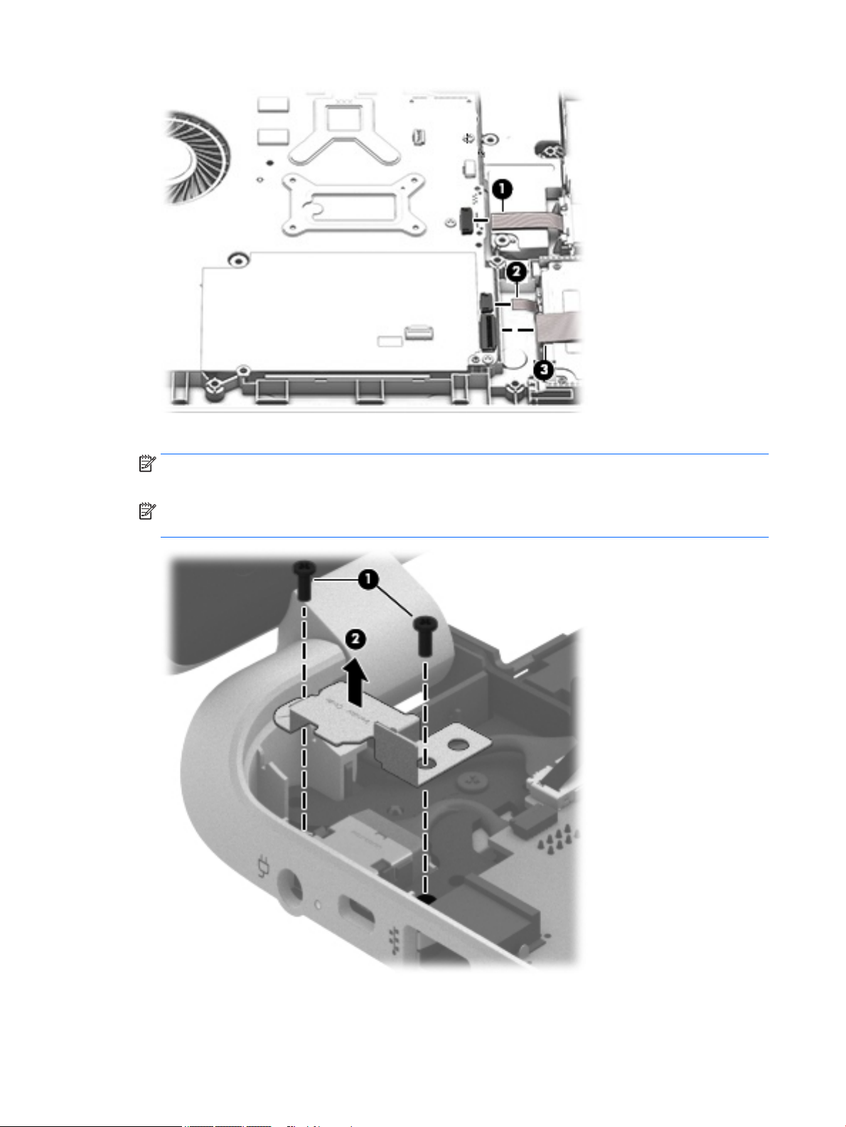
3. Remove the power connector cover by removing the screw(s) (1) and lifting the cover (2).
NOTE: The power connector cover has two screws, however, the screw on the left is removed during
the base enclosure and top cover removal process.
NOTE: You will remove the power connector after you have removed the system board. This
procedure is to remove the power connector cover if did not remove it when removing the display panel.
4. Remove the six Phillips screws (1).
52 Chapter 6 Removal and replacement procedures for Authorized Service Provider parts
Page 61

5. Lift the system board (2), and then remove the system board (3) by sliding it up and to the right at
an angle.
Reverse this procedure to install the system board.
Speakers
Description Spare part number
Speaker Kit (includes left and right front speakers and cables) 763717-001
Before removing the speakers, follow these steps:
1. Shut down the computer. If you are unsure whether the computer is off or in Hibernation, turn
2. Disconnect all external devices connected to the computer.
3. Disconnect the power from the computer by first unplugging the power cord from the AC outlet and
4. Remove the battery (see Battery on page 26),
5. Remove the optical drive (see Optical drive on page 27).
6. Remove the top cover from the base enclosure (see Base enclosure on page 30).
7. Remove the WLAN module (see WLAN module on page 42).
8. Remove the system board (see System board on page 50).
the computer on, and then shut it down through the operating system.
then unplugging the AC adapter from the computer.
Component replacement procedures 53
Page 62

Remove the speakers:
1. Turn the computer, with the front edge toward you.
2. Remove two screws (1).
3. Disengage the cables, and then remove the front speakers (2).
Reverse this procedure to install the speakers.
Memory modules
Description Spare part number
2 GB memory module 691739-005
4 GB memory module 691740-005
8 GB memory module 693374-005
Before removing a memory module, follow these steps:
1. Shut down the computer. If you are unsure whether the computer is off or in Hibernation, turn
the computer on, and then shut it down through the operating system.
2. Disconnect all external devices connected to the computer.
3. Disconnect the power from the computer by first unplugging the power cord from the AC outlet and
then unplugging the AC adapter from the computer.
4. Remove the battery (see Battery on page 26),
5. Remove the optical drive (see Optical drive on page 27).
6. Remove the top cover from the base enclosure (see Base enclosure on page 30).
54 Chapter 6 Removal and replacement procedures for Authorized Service Provider parts
Page 63

7. Remove the WLAN module (see WLAN module on page 42).
8. Remove the system board (see System board on page 50).
Remove the memory module:
1. Turn the system board over.
2. Spread the retaining tabs (1) on each side of the memory module slot to release the memory module.
(The memory module tilts up.)
CAUTION: To prevent damage to the memory module, hold it by the edges only. Do not touch the
components on the memory module.
3. Slide the memory module forward (2) to remove it.
Reverse this procedure to install a memory module.
RTC battery
Description Spare part number
RTC battery 697917-001
Before removing the RTC battery, follow these steps:
1. Shut down the computer. If you are unsure whether the computer is off or in Hibernation, turn
2. Disconnect all external devices connected to the computer.
3. Disconnect the power from the computer by first unplugging the power cord from the AC outlet and
4. Remove the battery (see Battery on page 26),
5. Remove the optical drive (see Optical drive on page 27).
the computer on, and then shut it down through the operating system.
then unplugging the AC adapter from the computer.
Component replacement procedures 55
Page 64

6. Remove the top cover from the base enclosure (see Base enclosure on page 30).
7. Remove the WLAN module (see WLAN module on page 42).
8. Remove the system board (see System board on page 50).
Remove the RTC battery:
1. Turn the system board upside down.
2. Use a thin, non-conductive tool to remove the RTC battery (1) from the socket on the system board.
Reverse this procedure to install the RTC battery on computer models. When installing the RTC battery, make
sure the “+” sign faces up.
Power connector
Description Spare part number
Power connector 763699-001
Before removing the power connector cable, follow these steps:
1. Shut down the computer. If you are unsure whether the computer is off or in Hibernation, turn
the computer on, and then shut it down through the operating system.
2. Disconnect all external devices connected to the computer.
3. Disconnect the power from the computer by first unplugging the power cord from the AC outlet and
then unplugging the AC adapter from the computer.
4. Remove the battery (see Battery on page 26),
5. Remove the optical drive (see Optical drive on page 27).
6. Remove the top cover from the base enclosure (see Base enclosure on page 30).
7. Remove the WLAN module (see WLAN module on page 42).
8. Remove the system board (see System board on page 50).
56 Chapter 6 Removal and replacement procedures for Authorized Service Provider parts
Page 65

Remove the power connector cable:
NOTE: The power connector cover was removed during the system board removal.
1. Release the metal clip to disconnect the power connector cable (1) from the system board.
2. Disengage the cable from the clips (2).
3. Release the clips (3), and then remove the power connector cable (4).
Reverse this procedure to install the power connector cable and bracket.
Fan
Description Spare part number
Fan 765788-001
Before removing the Fan, follow these steps:
1. Shut down the computer. If you are unsure whether the computer is off or in Hibernation, turn
the computer on, and then shut it down through the operating system.
2. Disconnect all external devices connected to the computer.
3. Disconnect the power from the computer by first unplugging the power cord from the AC outlet and
then unplugging the AC adapter from the computer.
4. Remove the battery (see Battery on page 26),
5. Remove the optical drive (see Optical drive on page 27).
6. Remove the top cover from the base enclosure (see Base enclosure on page 30).
7. Remove the WLAN module (see WLAN module on page 42).
8. Remove the system board (see System board on page 50).
Remove the fan:
1. Turn the system board upside down.
2. Disconnect the fan cable from the system board, and then remove the piece of tape that secures the fan
to the heat sink (1).
Component replacement procedures 57
Page 66

3. Remove the 3 screws securing the fan to the unit (2) and lift the fan to remove it (3).
Reverse this procedure to install the fan.
Heat sink
Description Spare part number
For use only on computer models equipped with AMD processors and UMA graphics 764080-001
NOTE: To properly ventilate the computer, allow at least 7.6 cm (3 in) of clearance on the left side of
the computer. The computer uses an electric fan for ventilation. The fan is controlled by a temperature
sensor and is designed to turn on automatically when high temperature conditions exist. These conditions
are affected by high external temperatures, system power consumption, power management/battery
conservation configurations, battery fast charging, and software requirements. Exhaust air is displaced
through the ventilation grill located on the left side of the computer.
Before removing the heat sink, follow these steps:
1. Shut down the computer. If you are unsure whether the computer is off or in Hibernation, turn
the computer on, and then shut it down through the operating system.
2. Disconnect all external devices connected to the computer.
3. Disconnect the power from the computer by first unplugging the power cord from the AC outlet and
then unplugging the AC adapter from the computer.
4. Remove the battery (see Battery on page 26),
5. Remove the optical drive (see Optical drive on page 27).
6. Remove the top cover from the base enclosure (see Base enclosure on page 30).
7. Remove the WLAN module (see WLAN module on page 42).
8. Remove the system board (see System board on page 50).
9. Remove the fan (see Fan on page 57).
58 Chapter 6 Removal and replacement procedures for Authorized Service Provider parts
Page 67

Remove the heat sink:
▲
Loosen the seven captive screws in the order listed on the heat sink (1), and then remove the heat sink
(2).
NOTE: The heat sink may vary by computer model and may have a different number of screws. The
heat sink is marked with the order the screws should be removed in. Follow the order shown.
NOTE: There is thermal paste between the heat sink and the processor.
Reverse this procedure to install the heat sink.
Component replacement procedures 59
Page 68

Power button board
Description Spare part number
Power button board (includes cable) 812177-001
Before removing the Power button board, follow these steps:
1. Shut down the computer. If you are unsure whether the computer is off or in Hibernation, turn
the computer on, and then shut it down through the operating system.
2. Disconnect all external devices connected to the computer.
3. Disconnect the power from the computer by first unplugging the power cord from the AC outlet and
then unplugging the AC adapter from the computer.
4. Remove the battery (see Battery on page 26),
5. Remove the optical drive (see Optical drive on page 27).
6. Remove the top cover from the base enclosure (see Base enclosure on page 30).
7. Remove the WLAN module (see WLAN module on page 42).
8. Remove the system board (see System board on page 50).
Remove the Power button board and cable:
1. Turn the top cover upside down, with the back edge toward you.
2. Remove the 2 Phillips screws securing the Power button board to the base enclosure (1).
3. Remove the Power button board (2).
NOTE: The Power button board's cable is attached to the base enclosure.
Reverse this procedure to install the Power button board.
60 Chapter 6 Removal and replacement procedures for Authorized Service Provider parts
Page 69

7 Computer Setup (BIOS), TPM, and HP Sure
Start – Windows 10
Using Computer Setup
Computer Setup, or Basic Input/Output System (BIOS), controls communication between all the input and
output devices on the system (such as disk drives, display, keyboard, mouse, and printer). Computer Setup
includes settings for the types of devices installed, the startup sequence of the computer, and the amount of
system and extended memory.
NOTE: Use extreme care when making changes in Computer Setup. Errors can prevent the computer from
operating properly.
Starting Computer Setup
NOTE: An external keyboard or mouse connected to a USB port can be used with Computer Setup only if
USB legacy support is enabled.
To start Computer Setup, follow these steps:
▲
Start Computer Setup.
●
Computers or tablets with keyboards:
▲ Turn on or restart the computer, and when the HP logo appears, press f10 to enter
Computer Setup.
●
Tablets without keyboards:
▲ Turn off the tablet. Press the power button in combination with the volume down button until
the Startup menu is displayed, and then tap F10 to enter Computer Setup.
Using Computer Setup 61
Page 70

Navigating and selecting in Computer Setup
●
To select a menu or a menu item, use the tab key and the keyboard arrow keys and then press enter, or
use a pointing device to select the item.
NOTE: On tablets without keyboards, you can use your finger to make selections.
●
To scroll up and down, select the up arrow or the down arrow in the upper-right corner of the screen, or
use the up arrow key or the down arrow key on the keyboard.
●
To close open dialog boxes and return to the main Computer Setup screen, press esc, and then follow
the on-screen instructions.
To exit Computer Setup menus, choose one of the following methods:
●
To exit Computer Setup menus without saving your changes:
Select the Exit icon in the lower-right corner of the screen, and then follow the on-screen instructions.
‒ or –
Select Main, select Ignore Changes and Exit, and then press enter.
●
To save your changes and exit Computer Setup menus:
Select the Save icon in the lower-right corner of the screen, and then follow the on-screen instructions.
‒ or –
Select Main, select Save Changes and Exit, and then press enter.
Your changes go into effect when the computer restarts.
Restoring factory settings in Computer Setup
NOTE: Restoring defaults will not change the hard drive mode.
To return all settings in Computer Setup to the values that were set at the factory, follow these steps:
1. Start Computer Setup. See Starting Computer Setup on page 61.
2. Select Main, and then select Apply Factory Defaults and Exit.
NOTE: On select products, the selections may display Restore Defaults instead of Apply Factory
Defaults and Exit.
3. Follow the on-screen instructions.
4. To save your changes and exit, select the Save icon in the lower-right corner of the screen, and then
follow the on-screen instructions.
‒ or –
Select Main, select Save Changes and Exit, and then press enter.
Your changes go into effect when the computer restarts.
NOTE: Your password settings and security settings are not changed when you restore the factory settings.
62 Chapter 7 Computer Setup (BIOS), TPM, and HP Sure Start – Windows 10
Page 71

Updating the BIOS
Updated versions of the BIOS may be available on the HP website.
Most BIOS updates on the HP website are packaged in compressed files called SoftPaqs.
Some download packages contain a file named Readme.txt, which contains information regarding installing
and troubleshooting the file.
Determining the BIOS
To decide whether you need to update Computer Setup (BIOS), first determine the BIOS version on
your computer.
BIOS version information (also known as ROM date and System BIOS) can be accessed by pressing fn+esc (if
you are already in Windows) or by using Computer Setup.
1. Start Computer Setup. See Starting Computer Setup on page 61.
2. Select Main, and then select System Information.
3. To exit Computer Setup without saving your changes, select the Exit icon in the lower-right corner of
the screen, and then follow the on-screen instructions.
‒ or –
Select Main, select Ignore Changes and Exit, and then press enter.
To check for later BIOS versions, see Downloading a BIOS update on page 63.
Downloading a BIOS update
CAUTION: To reduce the risk of damage to the computer or an unsuccessful installation, download and
install a BIOS update only when the computer is connected to reliable external power using the AC adapter.
Do not download or install a BIOS update while the computer is running on battery power, docked in an
optional docking device, or connected to an optional power source. During the download and installation,
follow these instructions:
Do not disconnect power on the computer by unplugging the power cord from the AC outlet.
Do not shut down the computer or initiate Sleep.
Do not insert, remove, connect, or disconnect any device, cable, or cord.
1. Type support in the taskbar search box, and then select the HP Support Assistant app.
‒ or –
Select the question mark icon in the taskbar.
2. Select Updates, and then select Check for updates and messages.
3. Follow the on-screen instructions.
4. At the download area, follow these steps:
a. Identify the most recent BIOS update and compare it to the BIOS version currently installed on
your computer. Make a note of the date, name, or other identifier. You may need this information
to locate the update later, after it has been downloaded to your hard drive.
b. Follow the on-screen instructions to download your selection to the hard drive.
Make a note of the path to the location on your hard drive where the BIOS update is downloaded.
You will need to access this path when you are ready to install the update.
Using Computer Setup 63
Page 72

NOTE: If you connect your computer to a network, consult the network administrator before
installing any software updates, especially system BIOS updates.
BIOS installation procedures vary. Follow any instructions that are revealed on the screen after the download
is complete. If no instructions are revealed, follow these steps:
1. Type file in the taskbar search box, and then select File Explorer.
2. Select your hard drive designation. The hard drive designation is typically Local Disk (C:).
3. Using the hard drive path you recorded earlier, open the folder that contains the update.
4. Double-click the file that has an .exe extension (for example, filename.exe).
The BIOS installation begins.
5. Complete the installation by following the on-screen instructions.
NOTE: After a message on the screen reports a successful installation, you can delete the downloaded file
from your hard drive.
Changing the boot order using the f9 prompt
To dynamically choose a boot device for the current startup sequence, follow these steps:
1. Access the Boot Device Options menu:
●
Computers or tablets with keyboards:
▲ Turn on or restart the computer, and when the HP logo appears, press f9 to enter the Boot
Device Options menu.
●
Tablets without keyboards:
▲ Turn off the tablet. Press the power button in combination with the volume down button until
the Startup menu is displayed, and then tap F9 to enter the Boot Device Options menu.
2. Select a boot device, then press enter.
64 Chapter 7 Computer Setup (BIOS), TPM, and HP Sure Start – Windows 10
Page 73

TPM BIOS settings (select products only)
IMPORTANT: Before enabling Trusted Platform Module (TPM) functionality on this system, you must
ensure that your intended use of TPM complies with relevant local laws, regulations and policies, and
approvals or licenses must be obtained if applicable. For any compliance issues arising from your operation/
usage of TPM which violates the above mentioned requirement, you shall bear all the liabilities wholly and
solely. HP will not be responsible for any related liabilities.
TPM provides additional security for your computer. You can modify the TPM settings in Computer Setup
(BIOS).
NOTE: If you change the TPM setting to Hidden, TPM is not visible in the operating system.
To access TPM settings in Computer Setup:
1. Start Computer Setup. See Starting Computer Setup on page 61.
2. Select Security, select TPM Embedded Security, and then follow the on-screen instructions.
Using HP Sure Start (select products only)
Select computer models are configured with HP Sure Start, a technology that continuously monitors
the computer's BIOS for attacks or corruption. If the BIOS becomes corrupted or is attacked, HP Sure Start
automatically restores the BIOS to its previously safe state, without user intervention.
HP Sure Start is configured and already enabled so that most users can use the HP Sure Start default
configuration. The default configuration can be customized by advanced users.
To access the latest documentation on HP Sure Start, go to http://www.hp.com/support, and select
your country. Select Drivers & Downloads, and then follow the on-screen instructions.
TPM BIOS settings (select products only) 65
Page 74

66 Chapter 7 Computer Setup (BIOS), TPM, and HP Sure Start – Windows 10
Page 75

8 Using Setup Utility (BIOS) in Windows 8.1
Setup Utility, or Basic Input/Output System (BIOS), controls communication between all the input and output
devices on the system (such as disk drives, display, keyboard, mouse, and printer). Setup Utility (BIOS)
includes settings for the types of devices installed, the startup sequence of the computer, and the amount of
system and extended memory.
Starting Setup Utility (BIOS)
CAUTION: Use extreme care when making changes in Setup Utility (BIOS). Errors can prevent the computer
from operating properly.
▲
Turn on or restart the computer, quickly press esc, and then press f10.
Updating Setup Utility (BIOS)
Updated versions of Setup Utility (BIOS) may be available on the HP website.
Most BIOS updates on the HP website are packaged in compressed files called SoftPaqs.
Some download packages contain a file named Readme.txt, which contains information regarding installing
and troubleshooting the file.
Determining the BIOS version
To decide whether you need to update Setup Utility (BIOS), first determine the BIOS version on your
computer.
BIOS version information (also known as ROM date and System BIOS) can be accessed from the Start screen
by typing support, selecting the HP Support Assistant app, selecting My computer, and then selecting
System Information, or by using Setup Utility (BIOS).
To use Setup Utility (BIOS):
1. Start Setup Utility (BIOS) (see Starting Setup Utility (BIOS) on page 67).
2. Select Main, and then make note of the BIOS version.
3. Select Exit, select Exit Discarding Changes, and then follow the on-screen instructions.
To check for later BIOS versions, see Downloading a BIOS update on page 68.
Starting Setup Utility (BIOS) 67
Page 76

Downloading a BIOS update
CAUTION: To reduce the risk of damage to the computer or an unsuccessful installation, download and
install a BIOS update only when the computer is connected to reliable external power using the AC adapter.
Do not download or install a BIOS update while the computer is running on battery power, docked in an
optional docking device, or connected to an optional power source. During the download and installation,
follow these instructions:
●
Do not disconnect power from the computer by unplugging the power cord from the AC outlet.
●
Do not shut down the computer or initiate Sleep.
●
Do not insert, remove, connect, or disconnect any device, cable, or cord.
NOTE: If your computer is connected to a network, consult the network administrator before installing any
software updates, especially system BIOS updates.
1. From the Start screen, type support, and then select the HP Support Assistant app.
‒ or –
From the Windows desktop, click the question mark icon in the taskbar.
2. Click Updates and tune-ups, and then click Check for HP updates now.
3. Follow the on-screen instructions.
4. At the download area, follow these steps:
a. Identify the most recent BIOS update and compare it to the BIOS version currently installed on
your computer. If the update is more recent than your BIOS version, make a note of the date,
name, or other identifier. You may need this information to locate the update later, after it has
been downloaded to your hard drive.
b. Follow the on-screen instructions to download your selection to the hard drive.
Make a note of the path to the location on your hard drive where the BIOS update is downloaded.
You will need to access this path when you are ready to install the update.
BIOS installation procedures vary. Follow any instructions that appear on the screen after the download is
complete. If no instructions appear, follow these steps:
1. From the Start screen, type file, and then select File Explorer.
‒ or –
From the Windows desktop, right-click the Start button, and then select File Explorer.
2. Click your hard drive designation. The hard drive designation is typically Local Disk (C:).
3. Using the hard drive path you recorded earlier, open the folder that contains the update.
4. Double-click the file that has an .exe extension (for example, filename.exe).
The BIOS installation begins.
5. Complete the installation by following the on-screen instructions.
NOTE: After a message on the screen reports a successful installation, you can delete the downloaded file
from your hard drive.
68 Chapter 8 Using Setup Utility (BIOS) in Windows 8.1
Page 77

9 HP PC Hardware Diagnostics (UEFI) –
Windows 10
HP PC Hardware Diagnostics is a Unified Extensible Firmware Interface (UEFI) that allows you to run
diagnostic tests to determine whether the computer hardware is functioning properly. The tool runs outside
the operating system so that it can isolate hardware failures from issues that are caused by the operating
system or other software components.
NOTE: To start BIOS on a convertible computer, your computer must be in notebook mode and you must
use the keyboard attached to your tablet. The on-screen keyboard, which displays in tablet mode, cannot
access BIOS.
To start HP PC Hardware Diagnostics UEFI:
1. Start BIOS:
●
Computers or tablets with keyboards:
▲ Turn on or restart the computer, quickly press esc.
●
Tablets without keyboards:
▲ Turn on or restart the tablet, and then quickly hold down the volume down button.
‒ or –
Turn on or restart the tablet, and then quickly hold down the Windows button.
2. Press or tap f2.
The BIOS searches three places for the diagnostic tools, in the following order:
a. Connected USB drive
NOTE: To download the HP PC Hardware Diagnostics (UEFI) tool to a USB drive, see Downloading
HP PC Hardware Diagnostics (UEFI) to a USB device on page 70.
b. Hard drive
c. BIOS
3. When the diagnostic tool opens, select the type of diagnostic test you want to run, and then follow
the on-screen instructions. On a tablet, press the volume down button to stop a diagnostic test.
NOTE: If you need to stop a diagnostic test on computers or tablets with a keyboard, press esc.
69
Page 78

Downloading HP PC Hardware Diagnostics (UEFI) to a USB device
There are two options to download HP PC Hardware Diagnostics to a USB device:
Download the latest UEFI version:
1. Go to http://www.hp.com/go/techcenter/pcdiags. The HP PC Diagnostics home page is displayed.
2. In the HP PC Hardware Diagnostics section, click the Download link, and then select Run.
Download any version of UEFI for a specific product:
1. Go to http://www.hp.com/support, and then select your country. The HP Support page is displayed.
2. Click Drivers & Downloads.
3. In the text box, enter the product name, and then click Go.
– or –
Click Find Now to let HP automatically detect your product.
4. Select your computer, and then select your operating system.
5. In the Diagnostic section, follow the on-screen instructions to select and download the UEFI version
you want.
70 Chapter 9 HP PC Hardware Diagnostics (UEFI) – Windows 10
Page 79

10 Using HP PC Hardware Diagnostics (UEFI) in
Windows 8.1
HP PC Hardware Diagnostics is a Unified Extensible Firmware Interface (UEFI) that allows you to run
diagnostic tests to determine whether the computer hardware is functioning properly. The tool runs outside
the operating system so that it can isolate hardware failures from issues that are caused by the operating
system or other software components.
To start HP PC Hardware Diagnostics (UEFI):
1. Start Setup Utility:
▲
Turn on or restart the computer, quickly press esc.
2. Press or tap f2.
The BIOS searches 3 places for the diagnostic tools, in the following order:
a. Connected USB drive
b. Hard drive
c. BIOS
3. When the diagnostic tool opens, use the keyboard arrow keys to select the type of diagnostic test you
want to run, and then follow the on-screen instructions.
NOTE: If you need to stop a diagnostic test, press or tap esc.
Downloading HP PC Hardware Diagnostics (UEFI) to a USB device
NOTE: Instructions for downloading HP PC Hardware Diagnostics (UEFI) are provided in English only.
There are two options to download HP PC Hardware Diagnostics to a USB device:
Option 1: HP PC Diagnostics homepage— Provides access to the latest UEFI version
1. Go to http://hp.com/go/techcenter/pcdiags.
2. Click the UEFI Download link, and then select Run.
Option 2: Support and Drivers pages—Provide downloads for a specific product for earlier and later
versions
1. Go to http://www.hp.com.
2. Point to Support, located at the top of the page, and then click Download Drivers.
3. In the text box, enter the product name, and then click Go.
– or –
Click Find Now to let HP automatically detect your product.
Downloading HP PC Hardware Diagnostics (UEFI) to a USB device 71
Page 80

4. Select your computer model, and then select your operating system.
5. In the Diagnostic section, click HP UEFI Support Environment.
– or –
Click Download, and then select Run.
72 Chapter 10 Using HP PC Hardware Diagnostics (UEFI) in Windows 8.1
Page 81

11 Specifications
Computer specifications
Metric U.S.
Dimensions
Depth 279 mm 10.9 in
Width 419.5 mm 16.5 in
Height (rear) 27.75 mm 1.09 in
Weight
Input power
Operating voltage and current 19.5 V dc @ 2.31 A – 45 W
Temperature
Operating 5°C to 35°C 41°F to 95°F
Nonoperating ‑20°C to 60°C ‑4°F to 140°F
Relative humidity (noncondensing)
Operating 10% to 90%
Nonoperating 5% to 95%
Maximum altitude (unpressurized)
Operating ‑15 m to 3,048 m ‑50 ft to 10,000 ft
Nonoperating ‑15 m to 12,192 m ‑50 ft to 40,000 ft
NOTE: Applicable product safety standards specify thermal limits for plastic surfaces. The device operates well within this range of
temperatures.
2.824 kg 6.23 lb
Computer specifications 73
Page 82

43.9-cm (17.3-in) display specifications
Metric U.S.
Active diagonal size 43.9-cm 17.3-in
Thickness 6.0 mm 0.236 inch
Resolution 1600x900 (HD+WLED)
Surface treatment BrightView
Contrast ratio 500:1 (min)
Brightness 220 nits (typical)
Viewing angle SVA
Backlight WLED
Companion standard LVDS
74 Chapter 11 Specifications
Page 83

Hard drive specifications
1-TB* 750-GB* 500-GB*
Dimensions
Height 9.5 mm 9.5 mm 7.0 mm or 9.5 mm
Length 100.45 mm (max) 100.45 mm (max) 100.45 mm (max)
Width 69.9 mm 69.9 mm 70.1 mm
Weight 115.0 g 115.0 g 92.0 g
Interface type SATA SATA SATA
Transfer rate
Synchronous (maximum) 600 MB/sec (max) 600 MB/sec (max) 600 MB/sec (max)
Security ATA security ATA security ATA security
Seek times (typical read, including setting)
Single track 2 ms 2 ms 2 ms
Average (read/write) 12 ms 12 ms 12 ms
Maximum 22 ms 22 ms 22 ms
Logical blocks 1,938,921,461 1,465,149,168 1,048,576,000
Disk rotational speed 5400 rpm 5400 rpm 5400 rpm
Operating temperature 5–55°C
*1 GB = 1 billion bytes when referring to hard drive storage capacity. Actual accessible capacity is less.
NOTE: Certain restrictions and exclusions apply. Contact technical support for details.
Hard drive specifications 75
Page 84

DVD±RW SuperMulti DL Drive specifications
Applicable disc Read:
CD-DA, CD+(E)G, CD-MIDI, CD-TEXT, CD-ROM, CDROM XA, MIXED MODE CD, CD-I, CD-I Bridge (PhotoCD, Video CD), Multisession CD (Photo-CD, CDEXTRA, Portfolio, CD-R, CD-RW), CD-R, CD-RW,
DVD-ROM (DVD-5, DVD-9, DVD-10, DVD-18), DVDR, DVD-RW, DVD+R, DVD+RW, DVD-RAM
Center hole diameter 1.5 cm (0.59 in)
Disc diameter
Standard disc 12 cm (4.72 in)
Mini disc 8 cm (3.15 in)
Disc thickness 1.2 mm (0.047 in)
Track pitch 0.74 µm
Access time CD DVD
Random < 175 ms < 230 ms
Full stroke < 285 ms < 335 ms
Data transfer rate
24X CD-ROM 3,600 KB/sec
8X DVD-ROM 10,800 KB/sec
Write:
CD-R and CD-RW
DVD+R, DVD+RW, DVD-R, DVD-RW,
DVD-RAM
24X CD-R 3,600 KB/sec
16X CD-RW 2,400 KB/sec
8X DVD+R 10,800 KB/sec
4X DVD+RW 5,400 KB/sec
8X DVD-R 10,800 KB/sec
4X DVD-RW 5,400 KB/sec
2.4X DVD+R(9) 2,700 KB/sec
5X DVD-RAM 6,750 KB/sec
Startup time < 15 seconds
Stop time < 6 seconds
76 Chapter 11 Specifications
Page 85

12 Backup and recovery – Windows 10
This chapter provides information about the following processes. The information in the chapter is standard
procedure for most products.
●
Creating recovery media and backups
●
Restoring and recovering your system
For additional information, refer to the HP support assistant app.
▲
Type support in the taskbar search box, and then select the HP Support Assistant app.
‒ or –
Click the question mark icon in the taskbar.
IMPORTANT: If you will be performing recovery procedures on a tablet, the tablet battery must be at least
70% charged before you start the recovery process.
IMPORTANT: For a tablet with a detachable keyboard, connect the keyboard to the keyboard dock before
beginning any recovery process.
Creating recovery media and backups
The following methods of creating recovery media and backups are available on select products only. Choose
the available method according to your computer model.
●
Use HP Recovery Manager to create HP Recovery media after you successfully set up the computer. This
step creates a backup of the HP Recovery partition on the computer. The backup can be used to reinstall
the original operating system in cases where the hard drive is corrupted or has been replaced. For
information on creating recovery media, see Creating HP Recovery media (select products only)
on page 78. For information on the recovery options that are available using the recovery media, see
Using Windows Tools on page 79.
●
Use Windows tools to create system restore points and create backups of personal information.
For more information, see Recovering using HP Recovery Manager on page 80.
NOTE: If storage is 32 GB or less, System Restore is disabled by default.
Creating recovery media and backups 77
Page 86

Creating HP Recovery media (select products only)
If possible, check for the presence of the Recovery partition and the Windows partition. From the Start menu,
select File Explorer, and then select This PC.
●
If your computer does not list the Windows partition and the Recovery partition, you can obtain
recovery media for your system from support. See the Worldwide Telephone Numbers booklet included
with the computer. You can also find contact information on the HP website. Go to http://www.hp.com/
support, select your country or region, and follow the on-screen instructions.
You can use Windows tools to create system restore points and create backups of personal information,
Using Windows tools on page 61.
see
●
If your computer does list the Recovery partition and the Windows partition, you can use HP Recovery
Manager to create recovery media after you successfully set up the computer. HP Recovery media can
be used to perform system recovery if the hard drive becomes corrupted. System recovery reinstalls
the original operating system and software programs that were installed at the factory and then
configures the settings for the programs. HP Recovery media can also be used to customize the system
or restore the factory image if you replace the hard drive.
◦
Only one set of recovery media can be created. Handle these recovery tools carefully, and keep
them in a safe place.
◦
HP Recovery Manager examines the computer and determines the required storage capacity for
the media that will be required.
◦
To create recovery discs, your computer must have an optical drive with DVD writer capability, and
you must use only high-quality blank DVD-R, DVD+R, DVD-R DL, or DVD+R DL discs. Do not use
rewritable discs such as CD±RW, DVD±RW, double-layer DVD±RW, or BD-RE (rewritable Blu-ray)
discs; they are not compatible with HP Recovery Manager software. Or, instead, you can use a
high-quality blank USB flash drive.
◦
If your computer does not include an integrated optical drive with DVD writer capability, but you
would like to create DVD recovery media, you can use an external optical drive (purchased
separately) to create recovery discs. If you use an external optical drive, it must be connected
directly to a USB port on the computer; the drive cannot be connected to a USB port on an external
device, such as a USB hub. If you cannot create DVD media yourself, you can obtain recovery discs
for your computer from HP. See the Worldwide Telephone Numbers booklet included with
the computer. You can also find contact information on the HP website. Go to http://www.hp.com/
support, select your country or region, and follow the on-screen instructions.
◦
Be sure that the computer is connected to AC power before you begin creating the recovery media.
◦
The creation process can take an hour or more. Do not interrupt the creation process.
◦
If necessary, you can exit the program before you have finished creating all of the recovery DVDs.
HP Recovery Manager will finish burning the current DVD. The next time you start HP Recovery
Manager, you will be prompted to continue.
To create HP Recovery media:
IMPORTANT: For a tablet with a detachable keyboard, connect the keyboard to the keyboard dock before
beginning these steps.
1. Type recovery in the taskbar search box, and then select HP Recovery Manager.
2. Select Create recovery media, and then follow the on-screen instructions.
If you ever need to recover the system, see Recovering using HP Recovery Manager on page 80.
78 Chapter 12 Backup and recovery – Windows 10
Page 87

Using Windows Tools
You can create recovery media, system restore points, and backups of personal information using
Windows tools.
NOTE: If storage is 32 GB or less, System Restore is disabled by default.
For more information and steps, see the Get started app.
▲
Select the Start button, and then select the Get started app.
Restore and recovery
There are several options for recovering your system. Choose the method that best matches your situation
and level of expertise:
IMPORTANT: Not all methods are available on all products.
●
Windows offers several options for restoring from backup, refreshing the computer, and resetting
the computer to its original state. For more information see the Get started app.
▲ Select the Start button, and then select the Get started app.
●
If you need to correct a problem with a preinstalled application or driver, use the Reinstall drivers
and/or applications option (select products only) of HP Recovery Manager to reinstall the individual
application or driver.
▲ Type recovery in the taskbar search box, select HP Recovery Manager, select Reinstall drivers
and/or applications
●
If you want to recover the Windows partition to original factory content, you can choose the System
Recovery option from the HP Recovery partition (select products only) or use the HP Recovery media.
For more information, see Recovering using Recovering using HP Recovery Manager on page 80. If you
have not already created recovery media, see Creating HP Recovery media (select products only)
on page 78.
●
On select products, if you want to recover the computer's original factory partition and content, or if you
have replaced the hard drive, you can use the Factory Reset option of HP Recovery media. For more
information, see Recovering using HP Recovery Manager on page 80.
●
On select products, if you want to remove the recovery partition to reclaim hard drive space,
HP Recovery Manager offers the Remove Recovery Partition option.
For more information, see Removing the Removing the HP Recovery partition (select products only)
on page 82.
, and then follow the on-screen instructions.
Using Windows Tools 79
Page 88

Recovering using HP Recovery Manager
HP Recovery Manager software allows you to recover the computer to its original factory state by using
the HP Recovery media that you either created or that you obtained from HP, or by using the HP Recovery
partition (select products only). If you have not already created recovery media, see Creating HP Recovery
media (select products only) on page 78.
What you need to know before you get started
●
HP Recovery Manager recovers only software that was installed at the factory. For software not
provided with this computer, you must either download the software from the manufacturer's website
or reinstall the software from the media provided by the manufacturer.
IMPORTANT: Recovery through HP Recovery Manager should be used as a final attempt to correct
computer issues.
●
To use the Factory Reset option (select products only), you must use HP Recovery media. If you have
not already created recovery media, see Creating HP Recovery media (select products only) on page 78.
●
If your computer does not allow the creation of HP Recovery media or if the HP Recovery media does
not work, you can obtain recovery media for your system from support. See the Worldwide Telephone
Numbers booklet included with the computer. You can also find contact information from
the HP website. Go to http://www.hp.com/support, select your country or region, and follow the onscreen instructions.
IMPORTANT: HP Recovery Manager does not automatically provide backups of your personal data. Before
beginning recovery, back up any personal data you want to retain.
Using HP Recovery media, you can choose from one of the following recovery options:
NOTE: Only the options available for your computer display when you start the recovery process.
●
System Recovery—Reinstalls the original operating system, and then configures the settings for
the programs that were installed at the factory.
●
Factory Reset—Restores the computer to its original factory state by deleting all information from
the hard drive and re-creating the partitions. Then it reinstalls the operating system and the software
that was installed at the factory.
The HP Recovery partition (select products only) allows System Recovery only.
80 Chapter 12 Backup and recovery – Windows 10
Page 89

Using the HP Recovery partition (select products only)
The HP Recovery partition allows you to perform a system recovery without the need for recovery discs or a
recovery USB flash drive. This type of recovery can be used only if the hard drive is still working.
To start HP Recovery Manager from the HP Recovery partition:
IMPORTANT: For a tablet with a detachable keyboard, connect the keyboard to the keyboard dock before
beginning these steps (select products only).
1. Type recovery in the taskbar search box, select Recovery Manager, and then select
HP Recovery Environment.
‒ or –
For computers or tablets with keyboards attached, press f11 while the computer boots, or press and
hold f11 as you press the power button.
For tablets without keyboards:
Turn on or restart the tablet, and then quickly hold down the volume down button; then select f11.
‒ or –
Turn on or restart the tablet, and then quickly hold down the Windows button; then select f11.
2. Select Troubleshoot from the boot options menu.
3. Select Recovery Manager, and then follow the on-screen instructions.
Using HP Recovery media to recover
You can use HP Recovery media to recover the original system. This method can be used if your system does
not have an HP Recovery partition or if the hard drive is not working properly.
1. If possible, back up all personal files.
2. Insert the HP Recovery media, and then restart the computer.
NOTE: If the computer does not automatically restart in HP Recovery Manager, change the computer
boot order. See Changing the computer boot order on page 82.
3. Follow the on-screen instructions.
Restore and recovery 81
Page 90

Changing the computer boot order
If your computer does not restart in HP Recovery Manager, you can change the computer boot order, which is
the order of devices listed in BIOS where the computer looks for startup information. You can change
the selection to an optical drive or a USB flash drive.
To change the boot order:
IMPORTANT: For a tablet with a detachable keyboard, connect the keyboard to the keyboard dock before
beginning these steps.
1. Insert the HP Recovery media.
2. Access BIOS:
For computers or tablets with keyboards attached:
▲
Turn on or restart the computer or tablet, quickly press esc, and then press f9 for boot options.
For tablets without keyboards:
▲
Turn on or restart the tablet, and then quickly hold down the volume down button; then select f9.
‒ or –
Turn on or restart the tablet, and then quickly hold down the Windows button; then select f9.
3. Select the optical drive or USB flash drive from which you want to boot.
4. Follow the on-screen instructions.
Removing the HP Recovery partition (select products only)
HP Recovery Manager software allows you to remove the HP Recovery partition to free up hard drive space.
IMPORTANT: After you remove the HP Recovery partition, you will not be able to perform System Recovery
or create HP recovery media from the HP Recovery partition. So before you remove the Recovery partition,
create HP Recovery media; see Creating HP Recovery media (select products only) on page 78.
NOTE: The Remove Recovery Partition option is only available on products that support this function.
Follow these steps to remove the HP Recovery partition:
1. Type recovery in the taskbar search box, and then select HP Recovery Manager.
2. Select Remove Recovery Partition, and then follow the on-screen instructions.
82 Chapter 12 Backup and recovery – Windows 10
Page 91

13 Backing up, restoring, and recovering in
Windows 8.1
This chapter provides information about the following processes. The information in the chapter is standard
procedure for most models.
●
Creating recovery media and backups
●
Restoring and recovering your system
For additional information, refer to Help and Support.
▲
From the Start screen, type help, and then select Help and Support.
Creating recovery media and backups
The following methods of creating recovery media and backups are available on select models only. Choose
the available method according to your computer model.
●
Use HP Recovery Manager to create HP Recovery media after you successfully set up the computer. This
step creates a backup of the HP Recovery partition on the computer. The backup can be used to reinstall
the original operating system in cases where the hard drive is corrupted or has been replaced. For
information on creating recovery media, see Creating HP Recovery media (select models only)
on page 83. For information on the recovery options that are available using the recovery media, see
Recovering using HP Recovery Manager on page 85.
●
Use Windows tools to create system restore points and create backups of personal information.
For more information, see Using Windows tools on page 84.
NOTE: If storage is 32 GB or less, Microsoft System Restore is disabled by default.
Creating HP Recovery media (select models only)
IMPORTANT: If your computer does not list a Create recovery media option, you can obtain recovery media
for your system from HP. See the Worldwide Telephone Numbers booklet included with the computer. You
can also find contact information on the HP website. Go to http://www.hp.com/support, select your country
or region, and follow the on-screen instructions.
HP Recovery Manager is a software program that allows you to create recovery media (using either a flash
drive or a set of DVDs) after you successfully set up the computer. HP Recovery media can be used to perform
system recovery if the hard drive becomes corrupted. System recovery reinstalls the original operating
system and software programs that were installed at the factory and then configures the settings for the
programs. HP Recovery media can also be used to customize the system or restore the factory image if you
replace the hard drive.
●
Only one set of recovery media can be created. Handle these recovery tools carefully, and keep them in
a safe place.
●
HP Recovery Manager examines the computer and determines the required storage capacity for the
media that will be required.
Creating recovery media and backups 83
Page 92

●
To create recovery discs, your computer must have an optical drive with DVD writer capability, and you
must use only high-quality blank DVD-R, DVD+R, DVD-R DL, or DVD+R DL discs. Do not use rewritable
discs such as CD±RW, DVD±RW, double-layer DVD±RW, or BD-RE (rewritable Blu-ray) discs; they are not
compatible with HP Recovery Manager software. Or, instead, you can use a high-quality blank USB flash
drive.
●
If your computer does not include an integrated optical drive with DVD writer capability, but you would
like to create DVD recovery media, you can use an external optical drive (purchased separately) to
create recovery discs. If you use an external optical drive, it must be connected directly to a USB port on
the computer; the drive cannot be connected to a USB port on an external device, such as a USB hub. If
you cannot create DVD media yourself, you can obtain recovery discs for your computer from HP. See
Worldwide Telephone Numbers booklet included with the computer. You can also find contact
the
information on the HP website. Go to http://www.hp.com/support, select your country or region, and
follow the on-screen instructions.
●
Be sure that the computer is connected to AC power before you begin creating the recovery media.
●
The creation process can take an hour or more. Do not interrupt the creation process.
●
If necessary, you can exit the program before you have finished creating all of the recovery DVDs. HP
Recovery Manager will finish burning the current DVD. The next time you start HP Recovery Manager,
you will be prompted to continue.
To create HP Recovery media:
1. From the Start screen, type recovery, and then select HP Recovery Manager.
2. Select Create recovery media, and then follow the on-screen instructions.
If you ever need to recover the system, see Recovering using HP Recovery Manager on page 85.
Using Windows tools
You can use Windows tools to create system restore points and create backups of personal information.
NOTE: If storage is 32 GB or less, Microsoft System Restore is disabled by default.
For more information and steps, see Help and Support.
▲
From the Start screen, type help, and then select Help and Support.
Restore and recovery
There are several options for recovering your system. Choose the method that best matches your situation
and level of expertise:
IMPORTANT: Not all methods are available on all models.
●
Windows offers several options for restoring from backup, refreshing the computer, and resetting the
computer to its original state. For more information see Help and Support.
▲
From the Start screen, type help, and then select Help and Support.
●
If you need to correct a problem with a preinstalled application or driver, use the Reinstall drivers
and/or applications option of HP Recovery Manager to reinstall the individual application or driver.
▲
From the Start screen, type recovery, select HP Recovery Manager, select Reinstall drivers
and/or applications
84 Chapter 13 Backing up, restoring, and recovering in Windows 8.1
, and then follow the on-screen instructions.
Page 93

●
On select models, if you want to reset your computer using a minimized image, you can choose the HP
Minimized Image Recovery option from the HP Recovery partition or HP Recovery media. Minimized
Image Recovery installs only drivers and hardware-enabling applications. Other applications included in
the image continue to be available for installation through the Reinstall drivers and/or applications
option in HP Recovery Manager.
For more information, see Recovering using HP Recovery Manager on page 85.
●
If you want to recover the Windows partition to original factory content, you can choose the System
Recovery option from the HP Recovery partition (select models only) or use the HP Recovery media. For
more information, see Recovering using HP Recovery Manager on page 85. If you have not already
created recovery media, see
●
On select models, if you want to recover the computer's original factory partition and content, or if you
have replaced the hard drive, you can use the Factory Reset option of HP Recovery media. For more
information, see Recovering using HP Recovery Manager on page 85.
●
On select models, if you want to remove the recovery partition to reclaim hard drive space, HP Recovery
Manager offers the Remove Recovery Partition option.
For more information, see Removing the HP Recovery partition (select models only) on page 87.
Creating HP Recovery media (select models only) on page 83.
Recovering using HP Recovery Manager
HP Recovery Manager software allows you to recover the computer to its original factory state by using the
HP Recovery media that you either created or that you obtained from HP, or by using the HP Recovery
partition (select models only). If you have not already created recovery media, see Creating HP Recovery
media (select models only) on page 83.
What you need to know before you get started
●
HP Recovery Manager recovers only software that was installed at the factory. For software not
provided with this computer, you must either download the software from the manufacturer's website
or reinstall the software from the media provided by the manufacturer.
IMPORTANT: Recovery through HP Recovery Manager should be used as a final attempt to correct
computer issues.
●
HP Recovery media must be used if the computer hard drive fails. If you have not already created
recovery media, see Creating HP Recovery media (select models only) on page 83.
●
To use the Factory Reset option (select models only), you must use HP Recovery media. If you have not
already created recovery media, see Creating HP Recovery media (select models only) on page 83.
●
If your computer does not allow the creation of HP Recovery media or if the HP Recovery media does
not work, you can obtain recovery media for your system from support. See the Worldwide Telephone
Numbers booklet included with the computer. You can also find contact information from the HP
website. Go to http://www.hp.com/support, select your country or region, and follow the on-screen
instructions.
IMPORTANT: HP Recovery Manager does not automatically provide backups of your personal data. Before
beginning recovery, back up any personal data you want to retain.
Using HP Recovery media, you can choose from one of the following recovery options:
NOTE: Only the options available for your computer display when you start the recovery process.
Restore and recovery 85
Page 94

●
System Recovery—Reinstalls the original operating system, and then configures the settings for the
programs that were installed at the factory.
●
Minimized Image Recovery (select models only)—Reinstalls the operating system and all hardwarerelated drivers and software, but not other software applications.
●
Factory Reset—Restores the computer to its original factory state by deleting all information from the
hard drive and re-creating the partitions. Then it reinstalls the operating system and the software that
was installed at the factory.
The HP Recovery partition (select models only) allows System Recovery and, on select models, Minimized
Image Recovery.
Using the HP Recovery partition (select models only)
The HP Recovery partition allows you to perform a system recovery or, on select models, minimized image
recovery without the need for recovery discs or a recovery USB flash drive. This type of recovery can be used
only if the hard drive is still working.
To start HP Recovery Manager from the HP Recovery partition:
1. From the Start screen, type recovery, select HP Recovery Manager, and then select HP Recovery
Environment
- or-
Press f11 while the computer boots, or press and hold f11 as you press the power button.
.
2. Select Troubleshoot from the boot options menu.
3. Select Recovery Manager, and then follow the on-screen instructions.
Using HP Recovery media to recover
You can use HP Recovery media to recover the original system. This method can be used if your system does
not have an HP Recovery partition or if the hard drive is not working properly.
1. If possible, back up all personal files.
2. Insert the HP Recovery media, and then restart the computer.
NOTE: If the computer does not automatically restart in HP Recovery Manager, change the computer
boot order. See Changing the computer boot order on page 86.
3. Follow the on-screen instructions.
Changing the computer boot order
If your computer does not restart in HP Recovery Manager, you can change the computer boot order, which is
the order of devices listed in BIOS where the computer looks for startup information. You can change the
selection to an optical drive or a USB flash drive.
To change the boot order:
1. Insert the HP Recovery media.
2. Start Computer Setup:
▲
Turn on or restart the computer, quickly press esc, and then press f9 for boot options.
3. Select the optical drive or USB flash drive from which you want to boot.
4. Follow the on-screen instructions.
86 Chapter 13 Backing up, restoring, and recovering in Windows 8.1
Page 95

Removing the HP Recovery partition (select models only)
HP Recovery Manager software allows you to remove the HP Recovery partition to free up hard drive space.
IMPORTANT: After you remove the HP Recovery partition, you can no longer use the Windows Refresh
option or the Windows option to remove everything and reinstall Windows. In addition, you will not be able to
perform System Recovery or Minimized Image Recovery from the HP Recovery partition. So before you
remove the Recovery partition, create HP Recovery media; see Creating HP Recovery media (select models
only) on page 83.
Follow these steps to remove the HP Recovery partition:
1. From the Start screen, type recovery, and then select HP Recovery Manager.
2. Select Remove Recovery Partition, and then follow the on-screen instructions.
Restore and recovery 87
Page 96

88 Chapter 13 Backing up, restoring, and recovering in Windows 8.1
Page 97

14 Power cord set requirements
The wide-range input feature of the computer permits it to operate from any line voltage from 100 to 120
volts ac, or from 220 to 240 volts ac.
The 3-conductor power cord set included with the computer meets the requirements for use in the country or
region where the equipment is purchased.
Power cord sets for use in other countries and regions must meet the requirements of the country or region
where the computer is used.
Requirements for all countries
The following requirements are applicable to all countries and regions:
●
The length of the power cord set must be at least 1.5 m (5.0 ft) and no more than 2.0 m (6.5 ft).
●
All power cord sets must be approved by an acceptable accredited agency responsible for evaluation in
the country or region where the power cord set will be used.
●
The power cord sets must have a minimum current capacity of 10 A and a nominal voltage rating of 125
or 250 V ac, as required by the power system of each country or region.
●
The appliance coupler must meet the mechanical configuration of an EN 60 320/IEC 320 Standard Sheet
C13 connector for mating with the appliance inlet on the back of the computer.
Requirements for all countries 89
Page 98

Requirements for specific countries and regions
Country/region Accredited agency Applicable note number
Argentina IRAM 1
Australia SAA 1
Austria OVE 1
Belgium CEBEC 1
Brazil ABNT 1
Canada CSA 2
Chile IMQ 1
Denmark DEMKO 1
Finland FIMKO 1
France UTE 1
Germany VDE 1
India ISI 1
Israel SII 1
Italy IMQ 1
Japan JIS 3
The Netherlands KEMA 1
New Zealand SANZ 1
Norway NEMKO 1
The People's Republic of China CCC 4
Saudi Arabia SASO 7
Singapore PSB 1
South Africa SABS 1
South Korea KTL 5
Sweden SEMKO 1
Switzerland SEV 1
Taiwan BSMI 6
Thailand TISI 1
The United Kingdom ASTA 1
The United States UL 2
1.
The flexible cord must be Type HO5VV-F, 3-conductor, 0.75mm2 conductor size. Power cord set fittings (appliance coupler and
wall plug) must bear the certification mark of the agency responsible for evaluation in the country or region where it will be
used.
90 Chapter 14 Power cord set requirements
Page 99

Country/region Accredited agency Applicable note number
2. The flexible cord must be Type SVT/SJT or equivalent, No. 18 AWG, 3-conductor. The wall plug must be a two-pole grounding
type with a NEMA 5-15P (15 A, 125 V ac) or NEMA 6-15P (15 A, 250 V ac) configuration. CSA or C-UL mark. UL file number must be
on each element.
3. The appliance coupler, flexible cord, and wall plug must bear a “T” mark and registration number in accordance with the
Japanese Dentori Law. The flexible cord must be Type VCTF, 3-conductor, 0.75mm
2
or 1.25mm2 conductor size. The wall plug
must be a two-pole grounding type with a Japanese Industrial Standard C8303 (7 A, 125 V ac) configuration.
4.
The flexible cord must be Type RVV, 3-conductor, 0.75mm2 conductor size. Power cord set fittings (appliance coupler and wall
plug) must bear the CCC certification mark.
5.
The flexible cord must be Type H05VV-F 3X0.75mm2 conductor size. KTL logo and individual approval number must be on each
element. Corset approval number and logo must be printed on a flag label.
6.
The flexible cord must be Type HVCTF 3X1.25mm2 conductor size. Power cord set fittings (appliance coupler, cable, and wall
plug) must bear the BSMI certification mark.
7. For 127 V ac, the flexible cord must be Type SVT or SJT 3 x 18 AWG, with plug NEMA 5-15P (15 A, 125 V ac), with UL and CSA or C-
UL marks. For 240 V ac, the flexible cord must be Type H05VV-F 3X0.75/1.00mm2 conductor size, with plug BS 1363/A with BSI
or ASTA marks.
Requirements for specific countries and regions 91
Page 100

92 Chapter 14 Power cord set requirements
 Loading...