HP 1710B Service and user manual

Page 1
Errata
Title & Document Type: 1710B Oscilloscope Operating and Service Manual
Manual Part Number: 01710-90906
Revision Date: March 1976
About this Manual

We've added this manual to the Agilent website in an effort to help you support your product. This manual provides the best information we could find. It may be incomplete or contain dated information, and the scan quality may not be ideal. If we find a better copy in the future, we will add it to the Agilent website.

HP References in this Manual

This manual may contain references to HP or Hewlett-Packard. Please note that Hewlett-Packard's former test and measurement, life sciences, and chemical analysis businesses are now part of Agilent Technologies. The HP XXXX referred to in this document is now the Agilent XXXX. For example, model number HP8648A is now model number Agilent 8648A. We have made no changes to this manual copy.

Support for Your Product

Agilent no longer sells or supports this product. You will find any other available product information on the Agilent Test & Measurement website:

www.agilent.com

Search for the model number of this product, and the resulting product page will guide you to any available information. Our service centers may be able to perform calibration if no repair parts are needed, but no other support from Agilent is available.

Page 2

Page 3

CERTIFICATION

Hewlett-Packard Company certifies that this instrument met its published specifications at the time of shipment from the factory. Hewlett-Packard Company further certifies that its calibration measurements are traceable to the United States National Bureau of Standards, to the extent allowed by the Bureau's calibration facility, and to the calibration facilities of other International Standards Organization members.

WARRANTY AND ASSISTANCE

This Hewlett-Packard , roduct is warranted against defects in materials and workmanship for a period of one year from the date of shipment. Hewlett-Packard will, at its option, repair or replace products which prove to be defective during the warranty period provided they are returned to Hewlett-Packard, and provided the preventive maintenance procedures in this manual are followed. Repairs necessitated by misuse of the product are not covered by this warranty. NO OTHER WARRANTIES ARE EX-PRESSED OR IMPLIED, INCLUDING, BUT NOT LIMITED TO, THE IMPLIED WARRANTIES OF MERCHANT-ABILITY AND FITNESS FOR A PARTICULAR PURPOSE. HEWLETT-PACKARD IS NOT LIABLE FOR CONSEQUENTIAL DAMAGES

Service contracts or customer assistance agreements are available for Hewlett-Packard products.

For any assistance, contact your nearest Hewlett-Packard Sales and Service Office. Addresses are provided at the back of this manual.

~

Page 4

OPERATING AND SERVICE MANUAL

OSCILLOSCOPE MODEL 1710B

(Including Options 001, 003, 011, 091, and 101)

SERIAL NUMBERS

This manual applies directly to instruments with serial numbers prefixed 1608A.

With changes described in Section VII this manual also applies to instruments with serial numbers prefixed 1420A through 1602A.

HEWLETT-PACKARD COMPANY/COLORADO SPRINGS DIVISION 1500 GARDEN CF THE GODS ROAD, COLORADO SPRINGS, COLORADO, U.S.A.

Manual Part Number 01710-90906 Microfiche Part Number 01710-90806

PRINTED: MARCH 1976

Page 5

SAFETY SUMMARY

The following general safety precautions must be observed during all phases of operation, service, and repair of this instrument. Failure to comply with these precautions or with specific warnings elsewhere in this manual violates safety standards of design, manufacture, and intended use of the instrument. Hewlett-Packard Company assumes no liability for the customor's failure to comply with these requirements.

GROUND THE INSTRUMENT.

To minimize shock hazard, the instrument chassis and cabinet must be connected to an electrical ground. The instrument is equipped with a three-conductor ac power cable. The power cable must either be plugged into an approved three-contact electrical outlet or used with a three-contact to two-contact adapter with the grounding wire (green) firmly connected to an electrical ground (safety ground) at the power outlet. The power lack and mating plug of the power cable meet international Electrotechnical Commission (IEC) safety standards.

DO NOT OPERATE IN AN EXPLOSIVE ATMOSPHERE.

Do not operate the instrument in the presence of flammable gases or fumes. Operation of any electrical instrument in such an environment constitutes a definite safety hazard.

KEEP AWAY FROM LIVE CIRCUITS.

Operating personnel must not remove instrument covers. Component replacement and internal adjustments must be made by qualified maintenance personnel. Do not replace components with power cable connected. Under certain conditions, dangerous voltages may exist even with the power cable removed. To avoid injuries, always disconnect power and discharge circuits before touching them.

DO NOT SERVICE OR ADJUST ALONE.

Do not attempt internal service or adjustment unless another person, capable of rendering first aid and resuscitation, is present.

USE CAUTION WHEN EXPOSING OR HANDLING THE CRT.

Breakage of the Cathode-ray Tube (CRT) causes a high-velocity scattering of glass fragments (implosion). To prevent CRT implosion, avoid rough handling or jarring of the instrument. Handling of the CRT shall be done only by qualified maintenance personnel using approved safety mask and gloves.

DO NOT SUBSTITUTE PARTS OH MODIFY INSTRUMENT,

Because of the danger of introducing additional hazards, do not install substitute parts or perform any unauthorized modification to the instrument. Return the instrument to a Hewlett-Packard Sales and Service Office for service and repair to ensure that safety features are maintained.

DANGEROUS PROCEDURE WARNINGS.

Warnings, such as the example below, precede potentially dangerous procedures throughout this manual instructions contained in the warnings must be followed.

Dangerous voltages, capable of causing death, are present in this instrument. Use extreme caution when handling, testing, and adjusting.

5.2.1/7

Page 6

S

C

TABLE OF CONTENTS
Page Section

v

pa σe
га KC.
1.197 11 !
I GENI ERAL INFORMATION 1-1
el l 11 Tu tau Justian 1.1
4 1-1. 1.1
10 1 1
1-0, Accessor/s Supplied 1.1
· . 1-10. Accessories Available 1.1
1-12. 1-1
1.14. Identification 1-2
II INST. ALLATION 2-1
· · 9.1 · Introduction 2-1
1 2.3 Initial Inspection 2-1
2-0.
9.5
Dower Corde and Recenteries 2.1
1.1 2.0. Power Requirements 2.1
· . 2.10 Repeaking for Shipmont 2-1
9-1
2-10, Repacking for Simplifient 2-1
III OPER ATION 31
s. ')
9.1
Introduction 3.1
3.3 Instrument Canabilities 3.1
9.7 Front and Beer name 0.1
٠, 1074 1 Descriptions 3-1
3-9.) General Operating
, 0.01 Instructions 3-1
3.11 Initial Turn on 3-1
2.19 Trons Align Adjustment 3.1
÷ 2.12 Forus and Astigmatism 0-1
1 0-10. A dinetmante 3.4
2.14 Acjustine Barformanas Chask 3.4
. 3 2 17 Operating Information 2.5
0°17.
2.10 ×
Auto Vergue Norm 2.5
0.19. 25 1
: 1 0.00 Deleved Sugar 0~0
2 E
3-22. პ~0
ი ⊭
, 3-24. Mixed Sweep 3-0
3-25. Application Procedures J-D
; 3-26. Peak-to-peak Voltage
A Measurements 3-0
3-27. DC Voltage Measurements 3-6
3-28. Time-interval Measurements 3-6
3-29. Frequency Calculation 3-6
1 3-30. Probe Compensation 3-6 ;
· 3-31. Time Difference Moasurements 3-7
3-32. X-Y Phase Measurements 3-7
IV PRIN CIPLES OF OPERATION 4-1
4.1 ' Introduction 4-1
· 4.3 Vertical Section Block Diagram 1.1
Input Attenuetare 4.1
, , ,5. Vertical Preamplifier and 4.1
同日 Control IC 4-1
2.4 Balay Lina 4.1
4-7. Vertical Output Amplifier 4-1
4-8, Horizontal Section Block
Diagram 4-1
4-9. Trigger Circuit 4-1
4-10. Sweep and Integrator Circuits 4-1
4-12. Holdoff Circuitry 4-1
4-13, Horizortal Preamplifier 4-1
4-14. Horizontal Output 4-1
4-15. Gate Circuitry 4-1
4-17. High-voltage Power Supply 4-2
4-21. Low-voltage Power Supply 4-2
4-24. Circuit Details 4-2
4-26. Attenuator Assemblies 4-2
4-27. General Information 4-2
4-29. Input 4-2
4-30. Attenuator Stages 4.2
4-34. Vertical Section 4-3
4-35. General Information 4-3
4-36. Preamplifier Stage 4-3
4-45. Preamplifier Controls 4-4
4-65. Delay Line Assembly 4-5
4-66. Vertical Output Amplifier 4-5
4-68. Horizontal Section 4-6
4-69. Main Trigger Circuitry 4-6
4-83. Main Sweep and Integrator 4-7
4-92. Delayed Sweep Circuitry 4-9
4-93. Horizontal Display Switch
Assembly 4-9
4-100. Horizontal Preamplifier 4-9
4-104. Horizontal Output 4-9
4-106. Gate Assembly and Calibrator 4-10
4-107. Gate Circuitry 4-10
4-117. Calibrator 4-11
4-118. CRT Controls 4-11
4-120. High-voltage Power Supply 4-11
4-128. Low-voltage Power Supply 4-12
4-130. ±15-volt Supplies 4-12
4-133. +5-volt Supply 4-12
4-134. +115-volt and +53.3-volt
Power Supplies 4-12
4-137. Flood-gun Filament Voltage 4-12
PERFO ORMANCE CHECK AND
ADJ USTMENTS 5-1
' • . • .•
6-1. Introduction 5-I
o-3. Test Equipment 5-1
0-D. Performance Checks 6-1
0-7. Adjustments 5-1
0-9. Performance Uneck Record 5-1
0-11. Front-panel Control Settings 5-1
0-14. Performance Check Procedures 5-1
b-15. Deflection Factor 5-1
0-18, Ualibrator Accuracy 5-2

iii

Page 7

TABLE OF CONTENTS (Cont'd)

Section

Page Section

5-21. Z-axis Blanking 55
5-24. Bandwidth 5-3
5-27. Triggering 5-5
5-30. Trigger-level Range 5-6
5-32 Common-mode Rejection 5-8
5-35. Sweep-time Accuracy 5-9
5-38. Delay Jitter 5-10
5-41 Differential Time Measurement
Accuracy 5-11
5-43 Rise Time 5-11
5.46 Adjustment Procedures 5-12
5.48 Low-voltage Power Supply
0.01 Adjustment 5-12
5.50 Intensity Set Adjustment 5-12
5.52 Gate-response. Amplitude and
0.02. Auto-focus Adjustments 5-13
5-54 Trace Align 5-14
5.56 Orthogonality and Pattern •••
Adjustments 5.14
5 59 Floadgun Pottorn and Intensity 0-1-1
0-00. Potio Adjustmente 5.15
E 00 Attenuator balance 0-10
, 0-00 , Adiustments 5.15
E 60 Mujustinentis 0-10
0-02. A divolmente 5.15
= 01 F wW Delence Adjustments 5 10
0-04.
E.CC
D-my Balance Adjustments 0-10
0-00. Sync Ampinier Balance E 10
= 00 0-10
5-68, Output-amplifier Balance E 17
9-17
5-70, Low-irequency Response E 177
Adjustments 0-17
5-72. Attenuator Compensation E 10
Adjustments 0-10
5-74. Calibrator-amplitude E 10
Adjustment 0-10
5-76. Vertical-gain Adjustmente 0-19
5-78. 5-mV Gain Adjustments 9-19
5-80. Trigger-recognition Threshold F 10
Adjustments 9-19
5-82. Horizontal-ampliner Gain F 00
5-20
5-84. XIO Amplither Balance
Adjustment 5-21
5-86. 1, 10 and 20 ns Sweep Time and
Linearity Adjustments 5-22
5-88. Coarse Main Sweep
Adjustments 5-23
5-90. Delayed-sweep Time
Adjustment 5-23
5-92. Fine Main Sweep
Adjustments 5-24
5-94. Vertical Pulse Response
Adjustmenta 5-24
Í.
1
5-96. X-Y Gain Adjustment 5-25
5-98. X-Y Phase Adjustment 5-26
Performance Check Record 5-27
VI REPL ACEABLE PARTS 6-1
61 Introduction 6 1
0-1, 61
0-3. Ordering information 0-1
VII MANU JAL CHANGES 7-1
7-1. Introduction 7-1
7-8. / Manual Changes 7-1
7-5. Options 7-1
i i 76. Special Options 7-1
7.9. Standard Options 7-1
7.10 Ontion 003 7-1
7.11 Ontion 101 7.1
7.12 Manual Changes Listing 7.2
,
VIII SCHE MATICS AND TROUBLE-
SHO OTING 8-1
8-1. Introduction 8-1
8-3. Schematics 8-1
8.8 Reference Designations 8-1
8-12 Component Locations 8-1
8.14 Preventive Maintenance 8-1
8.16 Mechanical Inspection 8.1
8.90 Switch Maintenance 8.3
0-20.
9.94
Bernovel and Bonlacement 8.3
0-24. CPT Removal and 0-0
0-20. Bonlagoment 8.3
0.07 Attenuator Removal and 0.0
0-27. Attenuator Removal and 04
0.00 0*4
ð-2ð. vertical Preamphiler Removal • •
and Replacement 8-4
8-29. Delay Line Removal and
Replacement 8-5
8-30. Removal and Replacement of
Assemblies in Horizontal
Section 8-5
8-36. Repair of Assemblies 8-6
8-37. General 8-6
8-39 . Replacement of Attenuator
Termination Resistors 8-6
8-41. Circuit Boards 8-6
8-43. Board Connections 8-6
8-44. Servicing Etched Circuit
Boards 8-8
8-45. Semiconductor Removal and
Replacement 8-8
8-46. Integrated Circuit Removal and ا ـ
Replacement 8-8
Page 8

Se

Table of Contents List of Illustrations

TABLE OF CONTENTS (Cont'd)

ct ion Page Section Page
8-47. Assembly A5 Integrated Circuit 8-55. Vertical Section Trouble-
Replacement 8-8 shooting 8-9
8-48. Troubleshooting 8-9 8-58, Horizontal Section Trouble-
8-51. DC Voltages 3-9 T shooting 8-9
í 8-52. Initial Troubleshooting 8-59. Low-voltage Power Supply
Ċ Procedure 8-9 Troubleshooting 8-10
8-54. Trouble Diagnosis 8-9
LIST OF ILLUSTRATIONS
Figure Title Page Figure Title Page
1
2.1 Tunes of Power Source Recenterles and 5-91 Horizontal linearity Adjustments 5-22
6 "1. Applicable Input Power Cable 5.99 Delaved.sween Adjustments 5-23
Part Numbers 2.1 0-222, 0 20
6-1 Chassis Parts Identification 6-2
3.1. Controls and Connectors 3-2 6-2. Front/Rear Panel Component
3-2 Divider Probe Adjustment Dienlay 3-6 Identification 6-4
3-3. X-Y Waveform 3-7
7-1. Option 003 Probe Power Schematic 7-3
4-1. Attenuator Simulified Block Diagram 4-3 7.2. Assembly A27 Component 1
4-2. Schmitt Simplified Block Diagram Identification 7-4
(Mixed Mode) 4-8 7-3. Assembly A26 Component
4-3. Gate Control Simplified Block Identification 7.4
Diagram 4-10 7.4. Option 101 Schematic 7-5
4-4. Time Base Simplified Block 7.5. Replacement for p/o Figure 8-19 7-6
Diagram 4.13 7-6. Replacement for Schematic 17 . 7-7
· · 77. Replacement for p/o Figure 8-20 7-8
5-1. Deflection Factor Test Setup 5-2 7-8. Replacement for Schematic 18 7-9
5-2. Calibrator Accuracy Test Setup 5-3 -
5-3. Z-axis Blanking Test Setup 5-4 8-1. Semiconductor Terminal
5-4, Bandwidth Test Setup 5-4 Identification 8-7
5-5. Main Triggering Test Setup 5-5 8-2. Board Assembly Identification 8-11
5-6. i Delayed Triggering Test Setup 5-7 8-3. Overall Block Diagram, Schematic 1 8-12
5-7. Trigger Level Test Setup 5-8 8-4. Overall Block Diagram, Schematic 2 8-13
5-8. CMRR Test Setup 5-8 8-5. Service Information, Channel A
5-9. Swee)-time Test Setup 5-10, Attenuator, Assembly A1 8-14
5-10. Rise Time Test Setup 5-11 8-6. Service Information, Channel B
5-11. Low-voltage Power Supply Attenuator, Assembly A2 8-16
1 2 i 1 Adjustment 5-12 8-7. Service Information, Vertical
5-12. Intensity Set Adjustment 5-13 • • Preamplifier, Assembly A3 8-18
5-13. Gate Assembly Adjustments 5-14 8-8. Service Information, Vertical Amplifier,
5 14. Intensity Limit Adjustment 5-14 Assembly A5 8-20
5-15. Vertical-preampliber Adjustments 5-16 S-9. Service Information, Display/Trigger 0.00
5-16. Sync Balance Adjustment 5-17 0.10 Switches, Assembly, Ab and A7 8-22
D-17. vertical Output Amplifier E 17 ö-10. Service information, Horizontal LAsplay 0.07
= 10 M 0-17
E 10
0 11 Switch Assembly Alu 0-24
0-10. Attenuator Adjustments 0-10 0-11. Service Information, Main Sweep 0.00
9-19 Adjust aspta 5.00 9.10 Samica Information Main Succes 0-20
5.00 Main Swaan Adjustments 5.21 0-12. Integrator Accombly All 8.72
0-20. 1 man pwcep rayusullents 0°61 - . 1 Incerawi, assentity All 0-20

Page 9

List of Illustrations List of Tables

Title

Figure

Model 1710B

po

Titla

LIST OF ILLUSTRATIONS (Cont'd)

Fi

р

- 40 C v.Dair T UD
1
8-13. Service Information, Dly'd Sweep
Trigger, Assembly A8
8-30 8-18. Service Information, Horizontal Output
Amplifier, Assembly A13
8-40
8-14. Service Information, Dly'd Sweep
Integrator, Assembly A9
8-32 8-19. Service Information, Gate Control/
Output, Assembly A14
8-42
/ 8-15. Service Information, Holdoff-comparator,
Assembly A12
8-34 8-20. Service Information, Gate Aseembly and
HV Power Supply, Assemblies
8-16. Service Information, Schmitt Control,
Assembly A8
8-36 8-21. A14 and A15
Service Information, Low-voltage Power
8-44
8-17. Service Information Horizontal
Preamplifier, Assembly A8
8-38 8-22. Supply, Assembly A17
Model 1710B I.C. Data
8-46
8-50

LIST OF TABLES

Table Title Page Table Title Page
1-1.
1-2.
Specifications 1-2
1-4
5-9. Vertical Adjustments 5-25
6-1. Abbreviations for Replaceable
5-1. Recommended Test Equipment 5-0 Parts List 6-1
5-2. Deflection Factor Accuracy 5-2 6-2. Replaceable Parts 6-5
5-3. Main Sweep Performance Check 5-9 6-3. List of Manufacturers' Codes 6-24
54. Delayed Sweep Performance
Check 5-9 ,
5-5. Power Supply Outputs 5-12 7-1. Manual Changes 7-1
5-6. Preliminary Sweep-time 7.2 Ontion 003 Parts List 7-1
Adjustments 5-23
5-7 Delayed eween Calibration 0.00 ·
Adjustmente 5.94 8. 1 Schematic Notes ደጋ
5.9 Main sween Calibration 0-44 2.9 Troubleshooting Guide havigentel 0-2
),,,,,,,,,,,,,,,,,,,,,,,,,,,,,,,,,,,,,, Adjustments 5-25 0-2. Section 8-10
Page 10
SECTION I GENERAL INFORMATION
1-1. INTRODUCTION.

1-2. The Hewlett-Packard Model 1710B Oscilloscope is a general-purpose, wide-band oscilloscope designed for bench or field service. It provides accurate measurements of high-frequency signals and fast rise-time pulses with 10-mV/div vertical deflection capability over the full 200 MHz bandwidth. Selectable input impedance of either 50 ohms or 1 megohm permits impedance selection that best meets measurement applications. Its low shunt capacitance of less than 11 pF reduces phase shift and signal loss in pulse or cw measurements.

1-3. This manual contains installation and operating instructions, as well as maintenance information for the Model 1710B. Insurument specifications and procedures for verifying proper operation are included. Procedures are also included for adjusting the instrument to its performance specifications. Schematic diagrams, the theory of operation, and troubleshooting information are provided for use in maintaining the instrument.

1-4. This section of the manual contains the performance specifications for the Model 1710B, and a list of the options available. It also lists the accessories supplied with the Model 1710B and other accessories that are available. Instrument and manual identification information are also included.

1-5. SPECIFICATIONS.

1-6. Table 1-1 is a complete list of the Model 1710B critical specifications that are controlled by tolerances. Table 1-2 contains general information that describes operating characteristics of the Model 1710B.

1-7. Any change in the specifications due to manufacturing, design, or traceability to the U.S. National Bureau of Standards will be listed on a manual change sheet included with this manual. The manual and manual change sheet supersede all previous information concerning specifications of the 1710B.

1-8. ACCESSORIES SUPPLIED.

1-9. The following accessories are supplied with the 1710B:

One Blue Light Filter, HP Model 10115A

One Front-panel Cover, HP Pari N. 01720-64101 One Vinyl Storage Pouch, HP I art No. 1540-0292

One 7.5-ft Power Cord. HP Part No. 8120-1521

  • Two 10:1 Divider Probes, HP Model 10014A
  • One Attenuator Resistor Kit, HP Part No. 5080-9696

1-10. ACCESSORIES AVAILABLE.

1-11. The following accessories are available for the 1710B:

Model 10020A Resistive Divider Probe Kit Mc Jel 1120A 500 MHz Active Probe Model 1125A Impedance Converter Probe Model 10491A Rack Mount Adapter

1-12. OPTIONS.

1-13. The following standard options extend the usefulness of the Model 1710B:

OPTION 001. This option supplies a fixed ac power cord in place of the normal detachable power cord. The option consists of the standard instrument modified by the addition of a power cord adapter plate (HP Part No. 01720-03201) and a power cord (HP Part No. 8120-1202).

OPTION 003. This option supplies two rear-panel connectors for probe power. The option consists of the standard instrument and assembly A18 (HP Part No. 01720-66516). Refer to Section VII for additional information.

OPTION 011. Replaces standard P31 phosphor CRT (V1) with internal graticule P11 phosphor CRT (HP Part No. 5083-4042). The option consists of replacing the CRT and assembly A14 with assembly A14 (HP Part No. 01720-66531).

OPTION 091. This option replaces the standard Model 10014A probes with HP Model 10016A 10:1 Voltage Divider Probes.

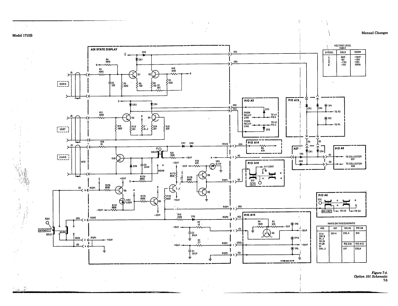
OPTION 101. This option adapts the Model 1710B for use with HP Model 1607A Logic State Analyzer to provide both digital and analog analysis. Refer to Section VII for additional information.

Page 11
General Information
1-14. INSTRUMENT AND MANUAL IDEN-TIFICATION.

1-15. Instrument identification by serial number is located on the rear panel. Hewlett-Packard uses a two-section serial number consisting of a four-digit prefix and a five-digit suffix, separated by a letter designating the country in which the instrument was manufactured. (A = U.S.A.; G = West Germany; J = Japan; U = United Kingdom.)

adopts the manual to instrument with serial numbers lower than that shown on the title page. Part numbers for the manual and the microfiche copy of the manual are also shown on the title page. Table 1-1. Specifications

1-16. This manual applies to instruments with reserial prefix number as shown on the title page. If

'changes have been made in the instrument since this manual was printed, a "Manual Changes" supplement supplied with the manual will define

these changes. Be sure to record these changes in

your manual. Backdating information in Section VII

VERTICAL DISPLAY MODES

Channel A. channel B. channels A and B displayed alternately on successive sweeps (ALT): channels A and B displayed by switching between channels at approx 1 MHz rate with blanking during switching (CHOP); channel A plus channel B (algebraic addition); X-Y (channel A vs. channel B).

VERTICAL AMPLIFIERS (2)

  • BANDWIDTH: (3 dB down from a 6 div reference signal).
  • DC-Coupled: dc to 200 MHz in both 50 ohm and high impedance input modes, 10 mV/div to 5 V/div; dc to 150 MHz at 5 mV/div.
  • AC-Coupled: lower limit is approx 10 Hz.
  • BANDWIDTH LIMIT: limits upper bandwidth to approx 20 MHz.
  • RISE TIME: <1.75 ns, 10 mV/div to 5 V/div; <2.3 ns at 5 mV/div (measured from 10% to 90% points of 6 div input step).
DEFLECTION FACTOR

  • Ranges: 5 mV/div to 5 V/div (10 calibrated positions) in 1, 2, 5 sequence, ±2% attenuator accuracy
  • Vernier: continuously variable between all ranges: extends maximum deflection factor to at least 12.5 V/div. Front panel light indicates when vernier is not in CAL position.
  • POLARITY: channel F may be inverted. front punel pushbutton.
  • Signal Delay: input signals are delayed sufficiently to view leading edge of input pulse without ødvanced trigger.
  • INPUT COUPLING: selectable, AC or DC, 50 ohms (dc) or ground. Ground position disconnects input connector and grounds amplifier input. INPUT RC (selectable)

AC and DC: 1 megohm ±2% shunted by approx 11 pF. 50 Ohm: 50 ohms ±2%, SWR <1.3:1 on E, 10, 20, and 50 mV ranges and <1.15:1 on all other ranges. MAXIMUM INPUT

  • AC and DC: ±250 V (dc + peak ac) at 1 kHz or ices. 50 Ohm: 5 V rms or ±250 V peak whichever is less. A + B OPERATION
  • Amplifier: bandwidth and deflection factors are unchanged; channel B may be inverted for A-B operation.

Differential (A-B) Common Mode: CMRR is at least 40 dB from dc to 5 MHz, decreasing to 26 dB at 50) MHz. Common mode signal amplitude equivalent to 12 cm with one vernier adjusted for optimum rejection.

TRIGGER SOURCE

Selectable from channel A, channel B, or composite.

  • CHANNEL A: all display modes triggered by channel A signal
  • CHANNEL B: all display modes triggered by channel B signal.
  • COMPOSITE: all display modes triggered by displayed signal.
VERTICAL OUTPUT

AMPLITUDE: one division of vertical deflection produces approx 100 mV output (dc to 25 MHz). CASCADED DEFLECTION FACTOR: 1 mV/div with

both vertical channels set to 10 mV/div.

CASCADED BANDWIDTH: dc to 5 MHz with bandwidth limi: engaged.

SOURCE RESISTANCE: approx 100 ohms.

SOURCE SELECTION: trigger source set to channel A selects channel A output, trigger source set to channel B selects channel B output.

HORIZONTAL DISPLAY MODES

Main, main intensified, delayed, mixed, and X-Y.

MAIN TIME BASE SWEEP

RANGES: 10 ns/div to 0.5 s/div (24 ranges) 1; 2, 5 sequence.

Accuracy
Main Sweep
Time/Div
Accuracy 0°C to 55°C
· . X1 X10
10 ns to 50 ns ±3% ±5%
100 ns to 20 ms ±2% ±3%
50 ms to 0.5 s ±3% ±3%
Model 1710B
Page 12

  • Vernier: continuously variable between all ranges; extends slowest sweep to at least 1.25 s/div. Vernier uncalibrated light indicates when vernier is not in CAL position.
  • Magnifier: expands all sweeps by a factor of 10; extends fastest sweep to I na/div.
SWEEP MODE

  • Normal: sweep is triggered by internal or external signal
  • Automatic: bright baseline displayed in absence of input signal from 10 ns/div to 20 ms/div. Triggering is same as normal above 40 Hz. Normal triggering is generally required for sweep speeds from 50 ms/div to 0.5 s/div.
  • Single: in Normal mode, sweep occurs once with same triggering as normal, reset pushbutton arms sweep and lights indicator: in Auto mode, sweep occurs once each time Reset pushbutton is pressed.
MAIN TIME BASE TRIGGERING

  • INTERNAL: dc to 100 MHz on signals causing 0.5 division or more vertical deflection, increasing to 1 division of vertical deflection at 200 MHz in all display modes. Triggering on line frequency is also selectable.
  • EXTERNAL: dc to 100 MHz on signals of 50 mV p-p or more increasing to 100 mV p-p at 200 MHz. Maximum input ±250 V (dc + peak ac) at 1 kHz or less. External input RC: approx 1 megohm shunted by

approx 15 pF. TRIGGER LEVEL AND SLOPE

  • internal: at any point on the vertical waveform displayed.
  • External: continuously variable from +1.0 V to --1.0 V on either slope of the trigger signal. +10 V to -10 V in divide by 10 mode (+10).
  • COUPLING: AC, DC, LF REJ, or HF REJ.
  • AC: attenuates signals below approx 10 Hz.

LF Reject: attenuates signals below approx 7 kHz. HF Reject: attenuates signals above approx 7 kHz. TRIGGER HOLDOFF: time between sweeps continuously variable, exceeding one full sweep from 10 ns/div to 50 ms/div.

MAIN INTENSIFIED

Intensified that part of main time base to be expanded to full screen in delayed time base mode. Delay control adjusts position of intensified portion of sweep. Rear panel intensity ratio control sets relative intensity of brightened segment.

DELAYED TIME BASE SWEED

Ranges: 10 ns/div to 20 ms/div (20 ranges) in 1, 2, 5 sequence.

Accuracy (0° to 55°C): same as main time base. Magnifler (0° to 55°C): same as main time base.

DELAYED TIME BASE TRIGGERING

  • INTERNAL: same as main time base except there is no Line Frequency triggering.
  • STARTS AFTER DELAY: delayed sweep automatically starts at end of delay period.
  • TRIGGER: with delayed trigger level control out of detent (starts after delay) delayed sweep is triggerable at end of delay period.
  • EXTERNAL: dc to 100 MHz on signals of 50 mV/p-p or more increasing to 100 mV p-p at 200 MHz. Maximum input ±250 V (dc + peak ac) at 1 kHz or less.
  • EXTERNAL INPUT RC: approx I megohm shunted by approx 15 pF.
TRIGGER LEVEL AND SLOPE

  • internal: at any point on the vertical waveform displayed when in the trigger mode.
  • External: continuously variable from +1.0 V to -1.0 V on either slope of the trigger signal, +10 V to --10 V in divided by 10 mode (+10).
  • COUPLING: AC, DC, LF REJ, or HF REJ.
  • AC: attenuates signals below approx 10 Hz.
  • LF Reject: attenuates signals below approx 7 kHz.
  • HF Reject: attenuates signals above approx 7 kHz.
  • DELAY TIME RANGE: 0.5 to 10X Main Time/Div settings of 20 ns to 0.5 s (minimum delay 50 ns).

Differential Time Measurement Accuracy (+15°C to 35°C)

Main Time Base Setting Accuracy
50 ns/aiv to 20 ms/div ±(0.5%+0.1% of full scale)
20 ns/div ±(1% +0.2% of full scale)
50 ms/div to 0.5 s/div ±3%

DELAY JITTER: <0.005% (1 part in 20 000) of maximum delay in each step.

MIXED TIME BASE

Dual time base in which the main time base drives the first portion of sweep and the delayed time base completes the sweep at the faster delayed sweep. Also operates in single sweep mode

X-Y OPERATION
BANDWIDTH

Y-axis (channel A): same as channel A.

X-axis (channel B): de to >1 MHz.

DEFLECTION FACTOR: 5 mV/div to 5 V/div (10 calibrated positions) in 1, 2, 5 sequence.

PHASE DIFFERENCE BETWEEN CHANNELS: <3°, de to 1 MHz.

R

Page 13

General Information

CATHODE-RAY TUBE AND CONTROLS

TYPE: post accelerator, approx 20.5 kV accelerating potential, aluminized P31 phosphor.

  • GRATICULE: 6 x 10 div internal graticule. 0.2 subdivision markings on major horizontal and vertical axes. 1 div = 1 cm. Rear panel adjustment aligns trace with graticule. Internal flood gun graticule illumination.
  • BEAM FINDER: returns trace to CRT screen regardless of setting of horizontal, vertical, or intensity controls.
  • INTENSITY MODULATION: +8 V, >50 ns width pulse blanks trace of any intensity, useable to 20 MHz for normel intensity, Input R, 1 kΩ ±10%. Maximum input ±10 V (dc + peak ac).
  • AUTO-FOCUS: automatically maintains beam focus with variations of intensity.
  • INTENSITY LIMIT: automatically limits beam current to decrease possible CRT damage. Circuit response time ensures full writing speed for viewing low duty cycle, fast rise time pulses.

REAR PANEL CONTROLS: astigmatism, pattern, main/delayed intensity ratio, and trace align.

GENERAL

REAR PANEL OUTPUTS: main and delayed gates, -0.7 V to +1.3 V capable of supplying approx 3 mA.

CALIBRATOR:

Type: 1 kHz ±15% square wave.

Voltage: 3 V p-p ±1%.

Rise Time: <0.1 μs.

POWER: 100, 120, 220, 240 Vac, -10% +5%; 48 to 440 Hz; 110 VA max.

  • WEIGHT: net, 12.9 kg (28.5 lb); shipping 17.9 kg (39.5 lb).
  • OPERATING ENVIRONMENT: temperature, 0 to +55°C; humidity, to 95% relative humidity at 40°C; altitude, to 4572 m (15 000 ft); vibration, vibrated in three planes for 15 min. each with 0.25 mm (0.010) excursion, 10 to 55 Hz.

DIMENSIONS: see outline drawing.

Page 14
SECTION II
INSTALLATION
2-1. INTRODUCTION

22. This section contains information and instructions necessary for installing and interfacing the Model 1710B Oscilloscope. Included arc initial inspection procedures, power and grounding requirements, installation instructions, and procedures for repackaging the instrument for shipment.

2-3. INITIAL INSPECTION.

2-4. This instrument was carefully inspected both mechnically and electrically before shipment. It should be free of mars or scratches and in perfect electrical order upon receipt. To confirm this, the instrument should be inspected for physical damage incurred in transit. If the instrument was damaged in transit, file a claim with the carrier. Check for supplied accessories (listed in Section I) and test the electrical performance of the instrument using the performance test procedures outlined in Section V. If there is damage or deficiency, see the warranty in the front of this manual.

Read the Safety Summary at the front of the manual before installing or operating the instrument.

2-5. POWER CORDS AND RECEPTACLES.

2-6. Figure 2-1 illustrates the standard configuration used for HP power ccrds. The HP part number directly above each drawing is the part number for an instrument power cord equipped with a connector of that configuration. If the appropriate power cord is not included with the instrument, notify the nearest HP Sales and Service Office and a replacement cord will be provided.

Figure 2-1. Types of Power Source Receptacles and Applicable Input Power Cable Part Numbers

2-7. POWER REQUIREMENTS.

2-8. The Model 1710B can be operated from any power source supplying 100 V, 120 V, 220 V, or 240 V (±10%), single phase, 48 to 440 Hz. Power dissipation is 100 VA maximum.

Instrument damage may result if the line-voltage selection switch is not correctly set for the proper input power, source.

2-9. The instrument is normally set at the factory for 120-volt operation. To operate the instrument from any other ac power source, proceed as follows:

a. Verify that Model 1710B power cable is not connected to any input power source.

b. Move LINE VOLTAGE SELECT switch on rear panel to 220 or 240 position.

c. Replace 1.5 Amperes LINE FUSE with 0.8 ampere fuse (HP Part No. 2110-0020) provided with instrument.

d. Connect input power cable to 220- or 240-Vac source.

2-10. REPACKING FOR SHIPMENT.

2-11. If the instrument is to be shipped to a Hewlett-Packard Sales/Service Office for service or repair, attach a tag showing owner (with address), complete instrument serial number, and a description of the service required.

2-12. Use the original shipping carton and packing material. If the original packing material is not available, the Hewlett-Packard Sales/Service Office will provide information and recommendations on materials to be used.

Page 15

Page 16
SECTION III
OPERATION
3-1. INTRODUCTION.

3-2. This section provides general operating instructions, power and warmup information, functional identification of all controls and connectors, and special applications information for the Model 1710B.

3-3. INSTRUMENT CAPABILITIES.

3-4. The instrument contains dual vertical preamplifiers for dual-channel operation. Each channel offers a choice of ac, high-Z dc, or 50-ohm input coupling. With the dual trace feature, displays can be obtained on either channel A or channel B or on both channels. Simultaneous display of two signals is possible in either chop or alternate mode of display. A+B and A--B modes of operation are also available. In addition, an X-Y mode of operation is provided. In this mode of display, the instrument becomes an X-Y display with inputs through channel A (Y-axis) and channel B (X-axis). The sensitivity of each axis is controlled by the channel A or channel B attenuator.

3-5. Ten calibrated switch settings on each vertical amplifier provide a deflection factor range from 5 mV/div to 5 V/div in 1, 2, 5 sequence. The vertical verniers permit continuous adjustment between calibrated steps and extends the least sensitive deflection factor (5 V/div) to at least 12.5 V/div.

3-6. Main horizontal amplifier sweep-speed settings from 10 ns/div to 0.5 s/div are available in a 1, 2, 5 sequence. The main sweep speed is calibrated when the SWEEP VERNIER control is set to CAL detent position.

3-7. FRONT-'AND REAR-PANEL DESCRIP-

3-8. Front- and rear-panel features are described in figure 3-1. Description numbers match the numbers on the illustration.

3-9. GENERAL OPERATING INSTRUC-TIONS.

3-10. Before connecting ac power to the Model 1710B, make sure the rear-panel line select switches are set to correspond to the voltage of the available power line. The instrument is normally set at the factory to operate from a 120-Vac source. If a differ-

ent power source is to be used, refer to Section II for settings of the line select switches and fuse type.

NOTE

In the following paragraphs all control numbers (in parentheses) refer to the numberical assignment in figure 3-1.

3-11. INITIAL TURN-ON. To place the Model 1710B into operation, perform the following steps:

a. Set INTENSITY (1) fully counterclockwise.

b. Set VERT DISPLAY to ALT (47).

c. Set INT TRIG to A (41).

d. Set vertical vernier controls (52) for channel A and channel B to CAL detent.

e. Set B INVERT switch (44) to out position.

f. Set vertical coupling for channel A and channel B to GND (50).

g. Set horizontal position (18) control to midrange.

h. Set main TIME/DIV (23) to 1 mSEC.

i. Set delayed TIME/DIV (24) to OFF.

j. Set main SWEEP VERNIER (28) to CAL detent.

k. Set AUTO/NORM (22) switch to AUTO.

1. Set main INT/EXT (34) trigger switch to INT.

m. Set LINE (38) switch to on and allow 5-minute warm-up period.

n. Adjust INTENSITY control (!) for just visible trace.

3-12. TRACE ALIGN ADJUSTMENT. The trace align adjustment compensates for external magnetic fields that may affect alignment of the horizontal trace with respect to the graticule. When the instrument is moved to a new location, trace alignment should be checked and adjusted if necessary. To align the trace, proceed as follows:

Page 17

Operation

Page 18

Operation

  • Model 1710B
    • 1. INTENSITY. Controls brightness of display.
    • 2. FOCUS. Control to provide the best focused display.
    • 3. MAG X10. In X10 position, sweep or X in X-Y mode, is magnified 10 times.
    • 4. DLY'D. Selects delayed sweep mode for display.
    • 5. MIXED. Selects mixed sweep mode for display.
    • 6: MAIN INTEN. Intensifies delayed sweep
    • 7.1 MAIN. Selects main sweek mode for display.
    • 8. X-Y. Display mode for providing X-axis deflection with signal applied to channel B input.
    • 9. BEAM FIND. Returns display to viewing area.
    • 10. delayed EXT + 10. Attenuates external trigger signal by factor of 10; increases external trigger range to ±10V.
    • 11. delayed INT/EXT. Selects internal or external delayed sweep triggering.
    • 12. delayed AC/DC. Selects drlayed sweep triggering coupling.
    • 13. delayed LF REJ. Attenuates delayed trigger signals below approximately 15 kHz.
    • 14. delayed HF REJ. Attenuates delayed trigger signals above approximately 1f kHz.
    • 15. delayed slope. Selects slope of delayed trigger signal that starts sweep.
    • 16. delayed EXT TRIG. BNC connector for delayed external trigger signal.
    • 17. DELAY. Selects delay time between start of main sweep and start of delayed sweep.
    • 18. horizontal POSITION. Controls coarse and fine horizontal position of display.
    • 19. delayed TRIGGER LEVEL. Selects amplitude point on trigger signal that starts delayed sweep.

  • 20. RESET. Resets sweep in SINGLE sweep mode; reset light indicates when sweep is
  • 21. SINGLE. Selects single or normal sweep
  • 22. AUTO/NORM
    • a. AUTO, Automatic sweep in absence of trigger signal; 'riggering occurs on trigger signals above 40 Hz.
    • b. NORM. Sweep is triggered only by applying trigger signal.
  • 23. main TIME/DIV. Controls sweep time in MAIN sweep mode.
  • 24. delayed TIME/DIV. Controls sweep time in MIXED and DLY'D sweep modes; controls intensified portion of sweep in MAIN INTEN sweep mode.
  • 25. UNCAL light. Refer to step 28.
  • 26. main TRIGGER LEVEL. Selects amplitude point on trigger signal that starts main sweep.
  • 27. TRIGGER HOLDOFF. Provides control of time between sweeps. With control fully counterclockwise, holdoff time is minimum.
  • 28. SWEEP VERNIER. Provides continuous control of sweep time between calibrated positions of TIME/DIV switch. UNCAL light indicates when control is out of CAL detent position.
  • 29. main EXT TRIG. BNC connector for main external trigger signal.
  • 30. main slope. Selects slope of main trigger signal that starts sweep.
  • 31. main HFREJ. Attenuates main trigger signals above approximately 15 kHz.
  • 32. main LF REJ. Attenuates main trigger signals below approximately 15 kHz.

NOTE LINE trigger is selected by engaging both HF REJ and LF REJ pushbutton switches simultaneously.

  • 33. main AC/DC. Selects main sweep triggering coupling.
  • 34. main INT/EXT. Selects internal or external main sweep triggering.
  • 35. main EXT + 10. Attenuates external trigger signal by factor of 10; increases external trigger range to ±10V.
  • 36. ____. Chassis ground connection for external equipment.
  • 37. power lamp. Lights when input power switch
  • 38. SCALE ILLUM. Controls brightness of scale illumination; control also contains input ac power on off switch. With control completely counterclockwise in POWER OFF position, ac power is disconnected internally.
  • 39. CAL 3V. Provides 1-kHz, negative square wnve of 3 volts ±1%.
  • 40. vertical UNCAL light. Lights when either channel A or channel B vernier is out of CAL detent.
  • v 41. internal trigger A. Selects channel A input signal for triggering.
  • 42. internal trigger B. Selects channel B input signal for triggering.
NOTE

Engaging both channel A and channel B internal trigger pushbutton switches results in composite triggering (COMP) on the displayed signal(s).

  • 4°, BW LIMIT 20 MHz. Display bandwidth limited to 20 MHz. Useful for noise reduction in normal and cascade operation.
  • 44. B INVERT. Control used to invert polarity of channel B signal display.
  • 45. vertical display A. Selects channel A input signal for display.
  • 46. vertical display B. Selects channel B input signal for display.
NOTE

The strates wester

Engaging both channel A and channel B vertical display pushbutton switches results in A+B (algebraic addition) display.

  • 47. ALT Displays each channel on alternate sweeps.
  • 48. CHOP. Displays each channel by switching between channels at 1 MHz rate.
  • 49. position A. Varies vertical position of channel A display.
  • 50. coupling. Selects capaciti e (AC), direct (DC), or 50-ohm coupling of input signal. GND position disconnects input signal and grounds input to vertical preamplifier.
  • 51. VOLTS/DIV. Selects vertical deflection factor nucessary for calibrated measurements.
  • 52. vernier. Provides continuous adjustment of volts div between calibrated positions of VOL/IS/DIV switch.
  • 53. INPUT. BNC connector for channel A input signal.
  • 54. ASTIG. Adjusts roundness of writing spot.
  • 55. PATI. Adjusts for uniform pattern over CRT viewing area.
  • 56. TRACE ALIGN. Adjust to align trace with horizontal graticule.
  • 57. INTEN RATIO. Adjusts intensity of intensified portion of sweep in MAIN INTEN mode of optration.
  • 58. Z AXiS. BNC connector for Z-axis input.
  • 59. VERTICAL OUTPUT. BNC connector for vertical amplifier output signal; provides approximately X10 gain, dc coupled, and source impedance of 100 ohms.
  • 60. MAIN gate. BNC connector for main gate output to external equipment.
  • 61. DELAYED gate. BNC connector for delayed gate output to external equipment.
  • 62. FUSI: AC power input fuse.
  • 63. LINE SELECTOR. Selects 100/120/220/240 ac operation.

Ċ

Page 19

Operation

a. Accomplish paragraph 3-11.

b. Using channel A POSITION control (49), position trace on center horizontal graticule line.

c. Using non-metallic alignment tool, adjust TRACE ALIGN (56) until trace aligns with horizontal graticule.

3-13. FOCUS AND ASTIGMATISM ADJUSTMENTS. Adjust focus and astigmatism as follows:

a. Turn INTENSITY control (1) fully counterclockwise.

b. Set LINE switch (38) to on position.

c. Set channel A controls as follows:

VOLTS/DIV (51)
Coupling (50) GND
VERT DISPLAY (45) A
Vernier (52) fully cw
Trigger select (42) В
POSITION (18) (49) a s required
HORIZONTAL DIŚPLAY (8) Х-Ү

d. Set INTENSITY (1) to observe dot.

e. Adjust FOCUS (2) and ASTIG (54) controls for best defined dot.

3-14. OPERATOR'S PERFORMANCE CHECK.

3-15. Model 1710B operation may be checked without additional test equipment by using the CAL 3 V output as a signal source. These tests will functionally check each display mode and operation of front-panel controls. To check specifications listed in table 1-1, refer to Section V for performance checks.

3-16. Operator's checks must be performed in the sequence given. Do not attempt to start a procedure in midsequence, as succeeding steps depend on control settings and results of previous steps. If any of the results are unobtainable, refer to Section V and the schematics at the rear of this manual.

a. Set Model 1710B controls as follows:
CHANNEL A
VOLTS/DIV -,5
Coupling * DC
Vernier •• CAL
POSITION 86 requ ired
VERTICAL DISPLAY -
Α
B INVERT out
CHANNEL B
VOLTS/DIV N/A
Coupling N/A
Vernier N/A
POSITION N/A
TIME BASE
Horizontal POSITION as required
SWEEP VERNIER CAL
HORIZ DISPLAY, MAIN
Main TIME/DIV . 0.5 mSEC
Delayed TIME/DIV 10 nSEC
AUTO/NORM AUTO
Main trigger INT
Main slope +/— +
Delayed slope +/ + +
Main TRIGGER LEVEL as required
Delayed TRIGGER LEVEL ccw detent
TRIGGER HOLDOFF ccw
MAG X10 out

b. Set INTENSITY, FOCUS, and POSITION controls for desired baseline display.

c. Apply CAL 3V output directly to channel A INPUT.

d. Adjust main TRIGGER LEVEL for stable display. Observe six positive-going pulses with leading edge of first and sixth pulse on first and eleventh vertical graticule lines respectively (±10%).

e. Set HORIZ DISPLAY for MAIN INTEN operation.

f. Set delayed TIME/DIV to 0.2 mSEC. Observe intensified portion of sweep.

NOTE

Intensified portion should cover 4 to 5 divisions.

g. Adjust DELAY control until intensified portion is centered on CRT.

h. Set HORIZ DISPLAY for DLY'D operation. Observe that intensified portion is expanded to 10 divisions.

i. Set HORIZ DISPLAY for MAIN INTEN operation.

j. Vary DELAY control. Observe that intensified portion moves smoothly along display.

k. Set delayed TIME/DI * control to 10 nSEC.

l. Turn SWEEP VERNIER counterclockwise to stop. Observe :5 or more pulses between first and eleventh graticule lines.

Page 20

Operation

m. Disconnect calibrator signal from vertical

n. TME/DIV to .1 SEC.

o. Set main TRIGGER LEVEL control to fully clockwise position.

p. Set AUTO/NORM switch to NORM.

q. Select SINGLE operation.

r. Press RESET pushbutton switch. Observe no sweep.

s. Turn main TRIGGER LEVEL fully counterclockwise. Observe one sweep; RESET indicator goes off after sweep.

t. Set AUTO/NORM switch to AUTO.

u. Press RESET pushbutton. Observe one sweep.

3-17. OPERATING INFORMATION.

3-18. The following paragraphs provide additional information concerning use of one special function over another.

3-19. AUTO VERSUS NORM. In AUTO operation, there will always be a recurrent sweep, except in trigger operation. A trigger of 40 Hz or higher overrides AUTO operation and produces a stable presentation. Adjustment of main TRIGGER LEVEL control may be necessary for a stable display. If the trigger is 40 Hz or less, NORM operation must be used. A trigger signal is always needed in NORM operation to generate a sweep.

3-20. In delayed operation, the delayed sweep is armed at the end of the delay time established by the DELAY control. When the delayed TRIGGER LEVEL switch is out of detent position, the delayed sweep is started by the first trigger signal after the delay time established by the setting of the DELAY control if the delayed TRIGGER LEVEL is adjusted for a stable display. In this mode, the delay time is longer than that set by the DELAY control. In starts after delay mode (detent position), the sweep starts immedia' ly after arming.

3-21. AC VERSUS DC. AC coupling removes the dc level of trigger signals and attenuates signals below 10 Hz. For example, if the trigger signal contains a dc voltage component, extreme levels can cause the signal to move out of trigger level range of the 1710B and lose the trigger operation.

3-22. DELAYED SWEEP. After obtaining a desired sweep, any portion can be expanded up to 1 ns per

division with 5% accuracy over center eight major divisions (X10 magnification) or 10 ns per division with 3% accuracy. This permits viewing of critical rise times or signal shapes with increased resolution. Because the sweeps are independent, the main VERNIER may be out of CAL detent and the delayed sweep will still be calibrated.

3-23. Sweep jitter can be reduced by using delayed trigger operation. By rotating the delayed TRIGGER LEVEL control out of detent, the delayed sweep starts on a new trigger. This reduces the jitter accumulated since start of the main sweep.

3-24. MIXED SWEEP. In MIXED SWEEP modes of operation, a dual sweep-speed display is presented. The main sweep drives the first portion of the sweep and the delayed sweep completes the display. This mode can also be selected when SINGLE sweep is desired.

C-25. APPLICATION PROCEDURES.

3-26. PEAK-TO-PEAK VOLTAGE MEASUREMENTS. To measure peak-to-peak voltage of an input signal, proceed as follows:

a. Accomplish paragraph 3-11.

b. Connect input signal to be measured to channel A INPUT connector.

c. Set channel A VOLTS/DIV control for signal display of at least three divisions in amplitude.

d. Set main TIME/DIV control so that display contains two or three cycles of input signal.

e. Adjust main TRIGGER LEVEL control for stable display.

f. Using channel A POSITION control, position negative peaks of input signal on horizontal graticule line near bottom of graticule.

g. Using horizontal POSITION control, position one positive peak of input signal on center vortical graticule line.

h. Count number of vertical divisions from most negative to most positive portions of waveform (estimate to nearest tenth of division).

i. Multiply number of divisions noted in step h by channel A VOLTS/DIV control setting for peakto-peak voltage of input signal.

NOTE

If the input signal is applied ti rough a divider probe, multiply the results obtained in step i by the attenuation factor of the probe.

Page 21
Operation

3-27. DC VOLTAGE MEASUREMENTS. To determine the de component of an input signal or a de level point on an input signal, proceed as follows:

a. Accomplish paragraph 3-11.

b. Connect input signal to be measured to channel A INPUT connector.

c. With channel A input coupling at GND position baseline on convenient horizontal graticule line using channel A POSITION control.

NOTE

Reference for positive dc voltages should be below the center horizontal graticule line; reference for negative dc voltages should be above the center horizontal graticule line. Once a particular horizontal graticule line is selected as reference, do not change channel A POSITION control.

d. Set channel A input coupling switch to DC position.

e. Set channel A VOLTS/DIV control so that point of input signal to be measured is as far as possible from zero-volt reference line selected in step c.

f. Using horizontal POSITION control, move point on signal to be measured until it rests on center vertical graticule line.

g. Count number of vertical divisions between zero-volt reference graticule line and point on signal to be measured (estimate to near st tenth of division).

h. Multiply number of divisions noted in step g by channel A VOLTS/DIV control setting for dc voltage measurement.

NOTE

If the input signal is applied through a divider probe, multiply the results obtained in step i by the attenuation factor of the probe.

3-28. TIME-INTERVAL MEASUREMENTS. To measure the time interval between two events of interest, proceed as follows:

a. Accomplish paragraph 3-11.

b. Connect signal to be measured to channel A INPUT connector.

c. Set main TIME/DIV control so that both events of interest are displayed on CRT.

d. Adjust main TRIGGER LEVEL control for stable display.

e. Using horizontal POSITION control, position one measurement point on signal to convenient vertical graticule line.

f. Using channel A POSITION control, position other measurement point on center horizontal graticule line.

g. Count horizontal divisions between two measurement points (estimate to nearest tenth of division).

h. Multiply number of divisions noted in step g by main TIME/DIV control setting for time interval between two events of interest.

3-29. FREQUENCY CALCULATION. To determine the approximate frequency of an input signal, proceed as follows:

a. Accomplish paragraph 3-28 using start and ending points of one cycle of input signal as events of interest.

b. Calculate input signal frequency using the following formula:

3-30. PROBE COMPENSATION. To adjust divider probes which have a compensation adjustment, proceed as follows:

a. Accomplish paragraph 3-11.

b. Connect divider probe cable to channel A INPUT connector.

c. Connect probe tip to PROBE ADJ terminal.

d. Set channel A VOLTS/DIV control for a square-wave display that has two or three divisions of vertical deflection.

Figure 3-2. Divider Probe Adjustment Display

Page 22

"e. Set main TIME/DIV control for horizontal display of/at least two full square waves.

f. Adjust divider probe compensation for correct display (see figure 3-2).

3-31. TIME DIFFERENCE MEASUREMENTS. To measure the time difference between two events having a common source, (e.g., propagation delay), proceed as follows:

a. Accomplish paragraph 3-11 for both channels A and B.

b. Connect one signal of interest to channel A INPUT connector.

c. Connect other signal of interest to channel B INPUT connector.

NOTE

Make sure reference signal is connected to channel A since the trigger signal for both channel A and channel B is obtained from channel A.

d. Set channel A and channel B VOLTS/DIV controls for desired vertical amplitude of display.

e. Set main TIME/DIV control so that the two events are at least four horizontal divisions apart.

f. If necessary, adjust main TRIGGER LEVEL control for stable display.

NOTE

If stable display is not obtainable, externally trigger the oscilloscope with the common source signal.

g. Using horizontal POSITION control, position first event on convenient vertical graticule line.

h. Using appropriate vertical POSITION control, position second event on center horizontal graticule line.

i. Count horizontal divisions between two measurement points (to nearest tenth of division).

j. Multiply number of divisions noted in step i by main TIME/DIV control setting for time difference between events.

3-32. X-Y PHASE MEASUREMENTS. The X-Y horizontal display mode of operation provides a method

of measuring phase differences between two signals of the same frequency (up to 3 MHz). In this mode, one input signal provides deflection along the horizontal axis (x) and the other input signal provides deflection along the vertical axis (y). The phase angle can be determined from the resulting lissajous pattern. There are other uses for this mode, such as, establishing a horizontal sweep from a free-running sweep oscillator.

3-33. To measure phase relationship between two signals of the same frequency, proceed as follows:

a. Connect one signal to channel A and the other to channel B . PUT connector.

b. Press VERT DISPLAY pushbutton switch A.

c. Press INT TRIG pushbutton switch B.

d. Press HORIZ DISPLAY pushbutton switch X-Y.

e. Set both channel A and channel B VOLTS/ DIV switches for a display of about 4 divisions (both horizontally and vertically).

f. Adjust POSITION controls until display is at center of CRT.

g. Measure distances A and B as shown in figure 3-3.

h. Divide A by B to obtain sine of phase angle (φ); (sine (φ) = A).

i. Determine sine value to determine phase angle.

j. Phase angle will be accurate to within 3° for signals up to 1 MHz.

Figure 3-3. X-Y Waveform

3-7/(3-8 blank)

Page 23

Page 24

SECTION IV
PRINCIPLES OF OPERATION
4-1. INTRODUCTION.

2. This section contains functional descriptions keyed to overall, simplified block diagrams of circuit groups (schematics 1 and 2). For simplicity, the block diagrams are drawn for function and do not show circuit details. Schematics are located in Section VIII.

4-3. VERTICAL SECTION BLOCK DIA-GRAM. (See schematic 1.)

4-4. INPUT ATTENUATORS. Channel A and channel B attenuators accept the input signals applied to the front-panel INPUT connectors. The attenuators have two functions: they select the type of input coupling (50Ω, DC, GND, AC); and, they set the vertical deflection factor (5 mV/div to 5 V/div) as selected by the front-panel VOLTS/DIV switches.

4-5. VERTICAL PREAMPLINER AND CONTROL IC. The vertical preamplifier and control integrated circuit accept a single-ended signal from the attenuator and convert it to a differential signal. The differential signal is then amplified and a portion of it is used for the sync amplifier while the main path is then acted upon by the polarity switch, vernier, position, and channel switch controls (in that sequence).

4-6. DELAY LINE. The delay line assembly delays the vertical signal approximately 50 nanoseconds. This delay allows the sweep to trigger before the vertical signal reaches the CRT plates.

4-7. VERTICAL OUTPUT AMPLIFIER. The vertical output amplifier provides drive to the CRT vertical deflection places.

4-8. HORIZONTAL SECTION BLOCK DIAGRAM. (See schematic 1.)

4-9. TRIGGER C/RCUIT. The internal sync amplifier provides the synchronization signal for the main and delayed trigger generators. The generators develop the trigger signals that start the main and delayed sweep. The trigger is also applied to an auto circuit that is used in AUTO mode only. The outputs of the generators are controlled by the level of the sync signal applied and the reset signal from the holdoff control circuit. When the reset signal is logic high, the generator is inoperative. When the reset signal is low, the generator is operational and a trigger signal

will be developed if there is an internal or external sync input.

4-10. SWEEP ANL) INTEGRATOR CIRCUITS. The sweep circuits initiate a horizontal sweep by the trigger signal that is applied to their inputs. A Miller integrator produces the horizontal sweep ramp; slope is controlled by the TIME/DIV switch on the front panel of the instrument. Output from the Miller integrator is applied through horizontal display control switches to the horizontal preamplifier circuit.

4-11. The horizontal sweep is also compared to a reference voltage by a comparator sweep length that drives the reset circuit. The reset circuit, along with other holdoff circuits, controls the timing sequence of the sweep ramp.

4-12. HOLDOFF CIRCUITRY. The holdoff circuit establishes the time interval between trigger points. This time interval is adjustable by the TRIGGER HOLDOFF control. The sweep ramp and the TIME/ DIV switch control the holdoff ramp generator. When the generator is activated, a ramp, determined by a selected holdoff capacitor and the TRIGGER HOLDOFF control, is produced. When the ramp reaches a predetermined voltage level, the reset circuit activates. This arms the trigger generator. Upon receipt of a new trigger signal, a new sweep is generated.

4-13. HORIZONTAL PREAMPLIFIER. The horizontal preamplifier provides amplification for the sweeptime ramp. A horizontal POSITION control establishes a reference level for the horizontal sweep. The BEAM FIND switch, when engaged, reduces emitter current in the output stage of the preamplifier so that the horizontal sweep will be returned to the viewing area of the CRT.

4-14. HORIZONTAL OUTPUT. The horizontal output stage provides drive to the CRT horizontal deflection plates.

4-15. GATE CIRCUITRY. (See :hematic 2.)

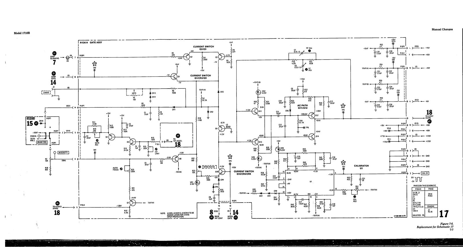
4-16. The gate assembly contains the circuitry necessary to control brightness of the CRT display. An intensity control circuit is used for brightening or blanking the CRT when necessary. Astigmatism, focus, pattern, and floodgun filament controls are part of the gate assembly. A 3-VOLT calibrator is also part of the gate assembly.

Page 25

Theory

4-17. HIGH-VOLTAGE POWER SUPPLY. (See schematic 2.)

4-18. The high-voltage power supply consists of the high voltage oscillator and a rectifying network. The high voltage oscillator produces cathode and grid voltages for the CRT. A secondary winding on the high voltage transformer provides voltage for the CRT cathode heater.

4-19. The CRT cathode voltage is sampled and fed back to a HV oscillator control circuit on the gate assembly. If the cathode voltage becomes more negative, less current is supplied to the oscillator. With less current supplied, the output amplitude of the oscillator is reduced and the cathode voltage will return to its normal operating value. If the cathode becomes less negetive, more current is supplied to the oscillator.

4-20. A tap on the secondary of the high voltage transformer is connected to a multiplier assembly. Output of the multiplier (X6) is connected to the CRT post accelerator terminal.

4-21. LOW-VOLTAGE POWER SUPPLY. (See schematic 2.)

4-22. The low-voltage power sup ly operates from an ac power source. The ac line is applied to the input power circuit where 100/120/220/240-Vac operation is selectable. The input power circuit contains the ac line protection fuse. The ac input is applied to a step-down power transformer.

4-23. Secondary outputs from the power transformer are applied to rectifiers and voltage regulator circuits, which 'convert input ac power to usable dc outputs of different voltage levels.

4-24. CIRCUIT DETAILS.

4-25. The following paragraphs provide a detailed explanation of individual circuits in the Model 1710B. Circuits that are identical for both channels are only explained for channel A.

4-26. ATTENUATOR ASSEMBLIES.

4-27. GENERAL INFORMATION. (See schematic 3.) The channel A attenuator assembly is a two section, cam-actuated attenuator. The first section is controlled by coupling switch A1S1. The second section is controlled by VOLTS/DIV switch A1S2. The attenuator components are closely mounted and their interrelationship is critical. If a malfunction occurs in an attenuator assembly, it is recommended that the attenuator board be replaced with a like unit.

4-28. In describing the attenuator assembly, only basic reference designators will be used. When

referring to table 6-2 (Section VI), prefix all basic reference designators (except A3 assembly components) with AI. See figure 4-1 for simplified block diagram of the attenuator.

4-29. INPUT. The input signal applied to channel A INPUT connector J1 is routed to coupling switch A1S1 through a 50-ohm stripline that is part of the etched circuit board. With A1S1 in its AC position. the input signal is applied through capacitor A1C1 to the first section of the attenuator. The value of AICI is such that signals below 10 Hz will be attenuated. In GND position, AIS1 disconnects the input signal and applies a ground to the attenuator input. In DC position, AISI forms a straight-through connection and applies the input signal directly to the high impedance section of the attenuator. In 500 position, A1S1 terminates the input signal in 50 ohms. The termination consists of two 100-ohm resistors, A1R1 and A1R2. These resistors are constructed of flame-proof material as a precaution against over-voltage application in the 500 position. The resistors are mounted in sockets to facilitate replacement.

4-30. ATTENUATOR STAGES. The VOLTS/DIV switch A1S2 controls a two-section cascaded attenuator. Each section consists of a group of attenuation networks. The high impedance section contains X1, X10, and X100 networks. The low impedance section contains X1, X2, and X5 networks. Each position of A1S2 cascades a network in the high impedance section with a network in the low impedance section. By cascading different network combinations, the attenuator provides 5 mV/div to 5 V/div vertical deflection. To obtain 5 mV/div, the attenuator activates a gain change of two in the vertical preamplifier.

4-31. A high-to-low impedance converter stage is inserted between the two sections of attenuator switch A1S2. The high frequency amplifier section of the impedance converter consists of field-effect transistor (FET) A1Q1 connected in a source follower configuration. Input to the gate of the FET is capacitively coupled through A1C5. Transistor A1Q2 functions as the current source for 1Q1. Emitter follower A1Q3 drives the resistive divider network of the low impedance section of attenuator switch A1S2. Under input over-voltage conditions, A1CR1 prevents reverse breakdown of the base-emitter junction of A1Q3.

4.32. The low frequency path of the input signal consists of error amplifier A3U1 and level shifter A3Q7. The error amplifier samples input and output signals within a frequency range of DC to 1 kHz and generates a correction signal to the high frequency amplifier to replace the missing low frequency signal components. The input signal sample is accomplished through a resistor divider network consisting

Page 26

Theory

Figure 4-1, Attenuator Simplified Block Diagram

of A1R8 and A3R64-A3R66. This provides isolation of capacitive loading to high frequency signals and over-voltage protection for the error amplifier. Gain of the low frequency path is set by adjusting the resistor divider ratio used to sample the output signal. Adjustment is accomplished with A3R74. Transistor A3Q7 functions as a level shifter for the low frequency correction signal. The low frequency correction signal is applied through current source A1Q2 to the high frequency amplifier circuit.

4-33. Channel B attenuator A2 functions identically as the channel A attenuator described in paragraphs 4-27 through 4-32. See schematic 4 for channel B component identification.

4-34. VERTICAL SECTION.

4-35. GENERAL INFORMATION. (See schematic 5.) Each channel preamplifier circuit consists of an integrated circuit (IC), associated biasing networks, and a chip transistor. All four ICs mounted on substrate assembly A3A1 provide two outputs: the main vertical signal and the internal sync signal.

4-36. PREAMPLIFIER STAGE. Since channel A and channel B are almost identical, only channel A will be described in detail. Where channel B differs from channel A, the difference will be discussed.

4-37. The input signal from attenuator A1 is applied to the channel A section of substrate assembly A3A1. The input amplifier stage is balanced (attenuators not in 5 mV/div) by main balance potentiometer A3R12 (A3R23 for channel B). A signal split is then accomplished with the two signals taken out separately (main signal and sync signal for time hase triggering).

4-38. The 5 mV/div vertical sensitivity is obtained by increasing the gain of the input amplifier stage by a factor of two. This is done by actively switching the emitter impedance of the input amplifier stage. The 5 mV/div range is balanced by potentiometer A3R9 (A3R24 for channel B) after A3R12 and A3R23 have been adjusted.

4-39. Outputs from channel A and channel B are combined in a common load resistor and applied to

Page 27

the input of delay line driver stage A3Q5/A3Q6. The sync outputs of channel A and channel B are combined in a common base stage and its output drives a balanced 3000 line to the input of main sync amplifier A10.

4-40. The output of A3Q3/A3Q4 is connected to delay line A4 through a bandwidth limit circuit. The bandwidth limit circuit limits the amplifier, 3 dB down to 20 MHz. A3Q3/A3Q4 operates as a differential common emitter amplifier.

4-41. BEAM FIND switch A8SIA (see schematic 15) supplies emitter bias (-15V) to amplifier A3Q3/A3Q4. When A3SIA is pressed, emitter bias is removed from the circuit. Signal sensitivity is reduced enough to return the trace to the viewing area of the CRT.

4-42. Each channel has a vertical POSITION control (R3 and R4) local d on the front panel. Vertical positioning of the viewed display is accomplished by adding or subtracting current in the main signal path. This results in shifting the vertical dc level of the output signal and causes the trace on the CRT to move up or down

443. With front panel vernier controls A1R1 and A2R1 in CAL detent position (attenuators not in 5 mV/div), the gain of each channel is adjusted by A3R1 (channel A) and A3R28 (channel B). By adjusting the ratio of bias current through two parallel connected junctions, the current division between the two junctions can be controlled. After the above adjustments have been made, the 5 mV/div gain of each channel is adjusted by A3R4 (channel A) and A3R27 (channel B).

4-44. An input signal applied to channel B can be inverted for A—B operation by front-panel B INVERT switch A6S1D. A saturated switch and bias circuit is also provided so that only a dc level change is needed to switch polarity. The dc level change (+15V) is supplied by the B INVERT switch when engaged.

4-45. PREAMPLIFIER CONTROLS (See schematic 7.) Internal Trigger Switch Assembly A6 and Vertical Display Switch Assembly A7 control the operation of substrate assembly A3A1. Control of the substrate assembly is described in the following paragraphs.

4-46. Channel A Display. Engaging VERT DISPLAY switch A7S1A selects the channel A input signal for display on the CRT. When angaged, A7S1A applies a constant high to the set input on flip-flop A7U1, causing its Q output (pire 13) to be held high and its Q output (pine 1) to be held low.

4-47. Since A7U1 is held in its set condition, the base bias applied to A7Q2 is more positive than that ap-

plied to A7Q1. Transistor A7Q2 conducts, and applies a disabling voltage to the channel B channel switch on assembly A3. With +V1 bias removed, output from the channel B preamplifier is inhibited.

4-48. Channel B Display. Engaging VERT DISPLAY switch A7S1B selects the channel B input signal for display on the CRT. When engaged, A7S1B applies a constant high to the reset input (pin 12) on flip-flop A7U1.

4-49. With A7S1B engaged and A7U1 held in its reset condition, the Q output of A7U1 is held high and the Q output is held low. With its base bias more positive, A7Q1 conducts and applies a disabling voltage to the channel A channel switch on assembly A3. With +V1 bias removed, output from the channel A preamplifier is inhibited.

4-50. Channel A and Channel B Displays. To display signals applied to both channels, VERT DISPLAY switches A7S1A and A7S1B are not engaged. The set and reset voltages applied to A7U1 are low. The flip-flop is controlled by inputs from either the ALT signal through OR/NOR gate A7U2A or the CHOP signal generated by chop oscillator A7U2B. The high and low inputs from either the ALT signal or the chop oscillator causes the Q and Q output of A7U1 to alternate between high and low logic levels. This action causes A7Q1 and A7Q2 to conduct alternately.

4-51. Channel A+B Display. To algebraically display input signals applied to both channels, VERT DIS-PLAY switches A7S1A and A7S1B are pressed simultaneously. With both switches engaged, --15V bias is removed from the emitter circuits of A7Q1 and A7Q2, cutting them off. This causes both channel A and channel B preamplifier stages on assembly A3 to be operational. In addition, with both A7S1A and A7S1B engaged, +15V is applied to the junction of A3VR5 and A3VR6. This increases the current available at the output circuit of the preamplifiers by effectively bypassing A3VR6.

4-52. For composite triggering in A+B or CHOP mode of operation, +15V is applied to the emitter circuits of A3Q5/A3Q6 through trigger switches A6S1A and A6S1B. This increases the current available at the emitters of sync amplifier A3Q5/A3Q6.

4-53. CHOP Mode Display. When CHOP made of display is selected by VERT DISPLAY switch A7S1D, a low is applied to pin 11 of OR/NOR gate A7U2B. With e low applied to pin 11, A7U2B operates as an astable multivibrator. The repetition rate of A7U2B, controlled by feedback capacitor A7C3, is approximately 1 MHz. The NOR gate output of A7U2B

Page 28

2

is applied as an input to flip-flop A7U1. The Q and Q output of the flip-flop control the operation of A7Q1/A7Q2 explained previously.

4-54. The NOR gate output of A7U2B is also applied to gate assembly A14 as a chop blanking signal. The chop blanking signal blanks the CRT trace during channel switching

4-55. ALT Mode Display. When AL/T mode of display is selected by VERT DISPLAY switch A7S1C, it releases all other display switches (A7S1A, A7S1B, and A7S1D). Electrically, A7S1C performs no function. It is mechanically connected to the other display switches so as to release them if they are engaged.

4-56. The ALT signal that is developed on main sweep assembly A8 is applied to an input on OR/ NOR gate A7U2A. At the start of the main sweep, the ALT signal goes low. With all inputs low, the NOR output of U2A (pin 5) is high. The high is applied as an input to flip.3op A7U1. At the end of the main sweep, the ALT signal becomes high and the NOR output of A7U2A becomes low. The negative transition at the input to flip.flop A7U1 causes it to change states. Thus, at the end of each sweep, channel control flip-flop A7U1 alternately disables channel A or channel B.

4-57. Channel A Sync Circuit. Internal sync switch assembly A6 contains the sync control circuitry necessary for selective internal triggering.

4-58. Engaging channel A sync switch A6S1A applies a low to the base of A7U3Q1 (pin 2). Since the channel B switch is not engaged, a high is applied to the base of A7U3Q2 turning it on. With A7U3Q5 conducting, the emitter level of A7U3Q1/A7U3Q2 (pin 3) is approximately the bias applied to A7U3 pin 13. With A7U3Q2 conducting, the bias developed at A7U3 pin 5 is applied to the channel B sync enabling network on assembly A3, preventing a channel B sync signal from being generated.

4-59. Channel B Sync Circuit. Engaging channel B sync switch A6S1B applies a low to the base of A7U3Q2. Since channel A switch is not engaged, a high is applied to the base of A7U3Q1 turning it on. With A7U3Q5 conducting, the emitter level of A7U3Q1/ A7U3Q2 (pin 3) is approximately the bias applied to A7U3 pin 13. With A7U3Q1 conducting, the bias developed at A7U3 pin 1 is applied to the channel A sync enabling network on assembly A3, preventing a channel A sync signal from being generated.

4-30. Composite Sync Circuit. When composite sync is selected, channel A and channel B sync switches (A6S1A and A6S1B) are engaged simultaneously. With both sync switches engaged, a ground is applied to the emitter circuit of A7U3Q5, cutting it off, and thereby disabling the emitter circuit of A7U3Q1/A7U3Q2. This

cuts off A7U3Q1 and A7U3Q2. In addition, with both sync switches engaged, —15V is applied to the emitter circuit of A7U3Q3 and A7U3Q4 through CHOP display switch A7S1D.

4-61. For composite sync, the outputs of A7U3Q3 and A7U3Q4 are controlled by the Q and Q outputs of A7U1. When the Q output of A7U1 is high (Q output low), A7U3Q4 conducts and A7U3Q3 is cut off. With A7U3Q4 conducting, its output (A7U3 pin 11) is approximately the bias voltage applied to its emitter (A7U3 pin 10). The bias at A7U3 pin 11 is applied to the B sync enabling network on assembly A3, preventing a channel B sync signal from being generated.

4-62. When the input to the base of A7U3Q3 is high (input to the base of A7U3Q4 is low), the collector output of A7U3Q3 (pin 8) is approximately the bias voltage applied to its emitter (A7U3 pin 7). The bias at A7U3 pin 8 is applied to the A sync enabling network on assembly A3, preventing a channel A sync signal from being generated.

4-63. Composite Sync Chop Mode Display. When composite sync is selected for CHOP mode of display, A7U3 is disabled by removing the -15V bias from both sections of the IC. This prevents A7U3 from applying a disabling voltage to either channel A or channel B enabling networks on assembly A3. The sync signal generated is a composite of signals applied to channel A and channel B.

4 34. Also, when composite sync is selected for CHOP mode of display, +15V is applied by CHOP switch A7S1D through sync switches A6S1A and A6S1B to emitter circuits of sync amplifier A3Q5/ A3Q6. The additional voltage source increases current available at the input to the sync amplifier (similar to A + B operation of the main signal amplifier A3Q3/A3Q4). When B INVERT switch A6S1D is engaged during this mode of operation, the channel B sync signal is inverted prior to developing the composite sync signal by applying +15V through A6R1 and A6S1D to a cross-over network in the channel B sync circuit on A3A1. This results in the channel B sync signal being inverted prior to combining with the channel A sync signal.

4-65. DELAY LINE ASSEMBLY. The output of the main signal amplifier A3Q3/A3Q4 is applied to delay line assembly A4. The delay line has a differential impedance of approximately 125 ohms and provides a time delay of approximately 50 nanoseconds. This delay is sufficient to allow the internal sync signal to trigger the time base and start the horizontal sweep. Without the insertion of this time delay in the signal path, the sweep would start after the signal reached the vertical deflection plates of the CRT and the leading edge of fast rise time signals would not be displayed.

4-66. VERTICAL OUTPUT AMPLIFIER. (See schematic 6.) The vertical output amplifier assembly A5

Page 29

Theory

consists of two integrated circuits with their associated control components. Integrated circuit A5U1 is the main vertical amplifier. It receives the differential signal from delay line assembly A4, amplifies it and applies it to output amplifier A5U2. High frequency adjustments A5C4, A5C6, A5C7, A5C13, A5R11, and A5R22 are adjusted for optimum pulse response.

4-67. Output amplifier A5U2 is a shunt feedback differential amplifier whose transimpedance converts the current gain of A5U1 to a voltage gain at the input of the CRT. The CRT's vertical section is the distributed line type with a 330-ohm terminating impedance.

4-68. HORIZONTAL SECTION.

4-69. MAIN TRIGGER CIRCUITRY. (See schematics 8 and 9.) The internal sync signal developed on preamplifier assembly A3 is connected to horizontal display switch assembly A10 through a 300-ohm impedance cable. Signal amplification is accomplished by sync amplifier stages A10Q1-A10Q5. Output from A10Q5 is applied through X-Y switch A10S1F to VERTICAL OUTPUT connector J4 on the rear panel of the instrument. Output from A10Q6 drives dual emitter followers A10Q7/A10Q8. Transistor A10Q7 supplies the main sync signal. Transistor A10Q8 supplies the delayed sync signal.

4-70. There are two sources of sync inputs to the main trigger circuit (see figure 4-4 for time base simplified block diagram). One input is from EXT TRIG connector J1 on the front panel of the instrument. The other input is from internal sync source A10Q7. The position of INT/EXT switch A8S10 determines which trigger source is selected. The external sync is applied to A8S10 through EXT +10 switch A8S1P. When A8S1P is engaged, a voltage divider network connected to the external input circuit reduces the input signal by a factor of 10.

4-71. The sync signal (external or internal) is applied to a high-frequency circuit and to a lowfrequency circuit (see schematic 9). The high-frequency circuit consists of A8Q1/A8Q2. This circuit readily passes all frequencies above 15 kHz. The low frequency circuit consists of A8U1/A8Q3 and readily passes all frequencies below 15 kHz.

4-72. The low-frequency path for the trigger signal is through the INT/EXT switch, AC/DC switch, and LF REJ switch to the input of an inverting operational amplifier A8U1. The output of A8U1 is applied to A8Q3 that functions as an emitter follower. The output of the low frequency path is applied to U2 pin 14. Front-panel TRIGGER LEVEL control R15 is part of the low frequency path.

4-73. With AC/DC switch A8S1N in its AC position, A8C1 blocks the dc component of the trigger signal.

When LF REJ switch A8S1M is engaged, the lowfrequency circuit is disconnected and the input to A8U1 is grounded. Pressing both the LF REJ switch and the HF REJ switch applies the line-frequency signal from primary ac power transformer T1 (see schematic 19) to the input of A8U1.

4-74. For high-frequency rejection, HF REJ switch A8S1L is engaged. This applies —15V through A8R7 to the gate of A8Q1. The source of A8Q1 and the emitter of A8Q2 are clamped by diodes A8CR2 through A8CR4 turning them off.

4-75. After conditioning by the high- and low-frequency bandpass circuits, the sync signal is applied to A8U2. This IC contains the pulse shaping network, arming circuitry, and trigger controls required to develop the trigger signal.

4-76. The sync signal is amplified by A8U2 and covered to differential signals. The differentially constructed signals are applied to the inputs of a pair of dual-input Schmitt trigger circuits located in the IC. Another Schmitt trigger on the IC controls the dual-input Schmitts.

4-77. At the end of the holdoff period, the holdoffcomparator develops a reset signal that is applied to the first Schmitt trigger on A8U2. The Schmitt trigger changes state, arming the second Schmitt trigger. When the applied trigger signal reaches the selected trigger level established, the second Schmitt trigger fires. One-half cycle later (when the trigger signal falls below the selected trigger level), the third Schmitt trigger fires producing trigger outputs from A8U2 (pin 1 and pin 2).

4.78. The input sensitivity on which A8U2 generates a trigger pulse is controlled by main trigger sensitivity potentiometer A8R47. The input sync signal slope on which A8U2 generates a trigger pulse is controlled by main slope switch A8S1K. This switch applies +5 volts to pin 16 for positive slope triggering and a ground for nega sve slope triggering.

4-79. The output of A8U2 (pin 2) is applied as one input of a dual-input current switch consisting of A8Q8 through A8Q10. The other input to the current switch is from bright-line auto generator A8U3. When the output of A8U2 (pin 2) or A8U3 (pin 5) goes low, either transistor A8Q8 or A8Q9 will conduct. With either transistor conducting, the current path for the current switch is through A8R36, A8R37, the conducting transistor, and A8R41. The signal developed at the high end of A8R41 is the main gate signal applied to the gate schmitt circuit (see schematic 14). In addition, when A8Q8 or A8Q9 conducts, A8Q10 cuts off. With A8Q10 cut off, a sweep ramp is generated by the integrator circuit (see schematic 10).

4-80. Transistor array A8U3 forms the bright-line outo circuit. In the absence of a sync signal, the output at A8U2 pin 2 is high, cutting off A8Q6. The comple-

Page 30

mentary low output at A8U2 pin 1 is applied to the base of transistor A8U3Q3 which drives the base of A8Q11 low causing A8C15 to change to the lower voltage level. The emitter of A8Q11 follows the negative charging of A8C11 which will reach its final charge in 25 milliseconds (unless a new sync signal occurs). With the lower voltage at the emitter of A8Q11, A8U3Q1 will now follow the auto signal applied to the base of A8U3Q5, A8U3Q1/A8U3Q2 form a Schmitt trigger circuit. With a sync signal applied. A8U3Q1 conducts constantly, holding off A8U3Q2. In the absence of a sync signal, the Schmitt trigger will follow the auto signal. When A8U3Q2 conducts, its collector goes low, turning on A8Q9, and, in turn, cutting off A8Q10. With A8Q10 cut off, the main sweep is activated. At the end of the main sweep, the reset signal goes high and is applied to A8U2 pin 4. With a high applied to A8U2 pin 4, the output at A8U2 pin 6 is low, turning on A8Q5. When A8Q5 conducts, it turns on A8U3Q5 which turns on A8U3Q1. With A8U3Q1 conducting, bias is removed from A8U3Q2, cutting it off. The output at A8U3 pin 5 goes high, turning off A8Q9 and turning on A8Q10. With A8Q10 conducting, a new sweep ramp will not start. At the end of the holdoff period, the reset signal goes low, the output at A8U2 pin 6 goes high, and A8Q5 turns off. When A8Q5 turns off, the cycle is repeated and a new sweep is initiated.

4-81. In NORM position of the AUTO/NORM switch A8S1K, +5V is applied to the base of A8U3Q4 turning it on. With A8U3Q4 conducting, forward bias is applied to the base of A8U3Q5 turning it on. This applies a constant forward bias to A8U3Q1 turning it on. With A8U3Q1 conducting, A8U3Q2 and A8Q9 are cut off. In the absence of a trigger signal, A8Q8 is also cut off and A8Q10 is conducting, preventing the generation of a sweep ramp. When a sync signal is applied to A8U2, the output at A8U2 pin 2 goes low. This turns on A8Q8 and turns off A8Q10, starting a new sweep.

4-82. For single sweep operation SINGLE switch A8S1I is pressed. With A8S1I engaged, +5V is applied through resistor network A8R30, A8R32, and A8R34 to A8U2 pin 5. This prevents A8U2 from developing a trigger signal. When RESET switch A8S1H is pressed, causes a negative-going spike to be applied to A8U2 pin 5. A8U2 is armed causing the output at A8U2, pin 6 to go high turning off A8Q5. A8Q4 and A8Q6 turn on and the reset lamp, DS4, on the front panel lights. A sync signal will produce one sweep.

4-83. MAIN SWEEP AND INTEGRATOR. (See schematic 10.) The main integrator, in conjunction with the sweep time controls, generates the main sweep ramp. The sweep is applied to the horizontal circuits.

4-84. The main integrator circuit is controlled by A8Q10 on assembly A8. When conducting, A8Q10 serves as a current source and prevents generation

of a main sweep ramp. When A8Q10 is cut off by the bright-line auto circuit or the receipt of a trigger signal, A1101B and A1102 turn off, removing reset current from the ramp capacitors. With A11Q2 cut off, Miller integrator circuit A11Q3/A11Q4 is activated. Depending upon the position of main TIME/DIV switch A11S1, a specific integrating capacitor is connected between the gate of A1103 and the collector of A11Q4. The TIME/DIV switch also connects a specific integrating resistor to the emitter circuit of A11Q7 that functions as a constant current source for the ramp capacitors. When A11Q2 turns off, the charging current drained by A11Q7 flows through the selected ramp capacitor (A11C11 through A11C17). This results in a linear, positivegoing ramp at the output of A11Q4. The ramp generated is applied to emitter follower A11Q6. The ovtput of A11Q6 is applied to the horizontal preamplifier through horizontal display switch assembly A10.

4.85. The output of constant current source A11Q7 is controlled by operational amplifier A11U1. A different reference voltage is developed for different ranges covered by the TIME/DIV switch This reference voltage is applied to AI1U1 pin 3. When different ranges are selected by the TIME/DIV switch. the values of the ramp capacitor, integrating resistor, and A11U1 reference voltage are changed. This action changes the ramp slope for various sweep speeds. The ramp slope can be varied for any selected range with main WEEP VERNIER potentiometer R12. The potentiometer is part of a voltage divider in parallel with the reference voltage applied to operational amplifier AIIUI. When the fastest range (10 ns) of the TIME/DIV switch is selected, capacitors A11C3 and A11C4 function as the ramp generator.

4.86. The sweep ramp, developed at the collector of A11Q4 is applied to the base of A12Q14. Conduction through A12Q14 and A12Q15 follows the positive-going sweep ramp and charges (positively) a particular holdoff capacitor (A12C2 through A12C8) in the collector circuits of A12Q1 through A12Q7. The holdoff capacitor that charges positively is determined by which transistor is conducting. Depending upon the position of TIME/DIV switch A11S1 (see schematic 10), base bias is applied to only one transistor which conducts. With the TIME/ DIV switch in either the 10-nanosecond or 20-narosecond position, no transistor is biased on. The holdoff capacitor, which is always in the circuit, is A13C1.

4-87. When the selected, holdoff capacitor charges to approximately +11V, transistor A12Q8 turns off and transistor A12Q9 turns on. The output of A12Q9 is the positive reset pulse applied to A8U2 (refer to paragraph 4-80.)

4-88. While the reset pulse is positive, A8Q8 and A8Q9 are turned off and A8Q10 turns on (see schematic 9). Since the base bias on A11Q1A (see schematic 9).

Page 31

matic 10) is more positive than A11Q1B, A11Q1B conducts heavily and discharges the selected ramp capacitor (A11C11 through A11C17) through A11Q2. When the voltage on the base of A11Q1A reaches the voltage level applied to the base of A11Q1B, both A11Q1B and A11Q2 turn on and the sum of currents at the gate of A11Q3 is zero and the ramp is reset.

4-89. As the sweep ramp resets, transistors A12Q14 and A12Q15 turn off (see schematic 13). The selected holdoff capacitor (A12C1-A12C8) discharges through A12R1 and TRIGGER HOLDOFF potentiometer R8. The position of R8 determines the rate of discharge and therefore the holdoff period. When the holdoff capacitor discharges to approximately +1.4V, A12Q10 turns off and A12Q11 turns on causing the reset signal to go negative. The negative transition of the reset signal arms trigger generator A8U2. Upon receipt of the next sync signal a new sweep is generated.

4-90. Transistor array A12U2 controls arming of the delayed sweep. DELAY potentiometer R7 establishes a reference voltage which is applied through isolation amplifier A12U1 to the base of comparator A12U2Q5. The high input impedance of A2U1 prevents load variations from affecting the setting of R7. When the main sweep ramp which is applied to the base of A12U2Q4 slightly exceeds the reference level applied to the base of A12U2Q5, A12U2Q4 conducts. turning on A12U2Q1 and turning off A12U2Q2. With A12U2Q2 turned off, A12U2Q3 conducts, arming the delayed trigger control A8U5. When main sweep only is selected by MAIN sweep switch A10S1E (see schematic 8), A12Q12 conducts, turning off A12Q13. With A12Q13 turned off, emitter bias is removed from comparator A12U2Q3/Q5 and the delay comparator control signal is inhibited. This prevents the delayed sweep from being generated.

4-91. The gate Schmitt circuit (see schematic 14) provides gate assembly A14 with the proper input for

Page 32

each display mode. The main and delayed sweep require their own respective gates, (see figure 4-2 for simplified block diagram of gate Schmitt circuit). In mixed mode of display, a gate is generated at the start of the main sweep and stops at the end of the delayed sweep. Depending upon which input is supplied, gate Schmitt (A8U7) changes state on the first positive control pulse and resets on the first negative control pulse. The pulses are provided by differentiating the control pulses. Buffered outputs are provided to rear-panel BNC connectors (J5 and J6) for both the main gate and delayed gate. In addition, the ALT signal is developed from the buffered main gate output signal. It is applied to vertical display switch A7.

4-92. DELAYED SWEEP CIRCUITRY. (See schematics 11 and 12). The delayed trigger, integrator, and sweep circuits function similarly to the main sweep circuit described previously. The one exception is that the slowest speed for delayed sweep is 20 milliseconds. Refer to paragraphs 4-69 through 4-90 for theory of operation of trigger, integrator, and sweep circuits.

4-93. HORIZONTAL DISPLAY SWITCH ASSEMBLY. (See schematic 8.) The horizontal display switch assembly selects the mode of horizontal display. The different modes are X10 magnification, delayed sweep, mixed sweep, main/delayed intensified sweep, main sweep, and X-Y display.

4-94. X10 Magnification. The MAG switch A10S1A supplies bias to one of two circuits in the horizontal preamplifier. When not engaged, A10S1A supplies forward bias to a X1 stage (A8Q28/A8Q29) on the horizontal preamplifier. When engaged, A10S1A removes the forward bias from the X1 stage and applies it to a X10 stage (A8Q26/A8Q27).

4-95. Delayed Sweep. The DLY'D sweep switch A10S1B performs two functions. When engaged, A10S1B reverse biases the main gate control circuit preventing development of a main gate signal. Also, when engaged, A10S1B routes the delayed sweep ramp to the horizontal preamplifier.

4-96. Mixed Sweep. The MIXED sweep switch AIOSIC performs two functions. When engaged, AIOSIC applies the main sweep ramp as the reset reference to the delayed sweep integrator circuit. Also, when engaged, AIOSIC routes the delayed sweep ramp to the horizontal preamplifier.

4-97. Main Intensified. The MAIN INTEN sweep switch A10S1D performs three functions. When engaged, A10S1D removes the +5V bias applied to intensity gate A14Q10. It also applies +5V to the delayed gate control circuit, disabling it. In addition, A10S1D routes the main sweep ramp to the horizontal preamplifier.

4-96. Main Sweep. The MAIN sweep switch A10S1E performs three functions. When engaged, A10S1E applies +5V to the delay comparator control and to the delayed gate control circuits disabling them. In addition, A10S1E routes the main sweep ramp to the horizontal preamplifier.

4-99. X-Y Control. The X-Y switch A10S1F performs a number of functions. When engaged, A10S1F removes the sync signal from rear-panel connector J4 and applies it to the horizontal preamplifier. It applies the x-y offset voltage to the horizontal preamplifier. The x-y control signal is grounded to prevent generation of the composite gate signal. It also inhibits the main and delayed gate signals applied to connectors on the rear of the instrument, innibits the sweep circuit, and unblanks the CRT.

4-100. HORIZONTAL PREAMPLIFIER. (See schematic 15.) The horizontal preamplifier converts the single-ended sweep from the sweep generator into a differential sweep for driving the horizontal output amplifier. During x-y operation, horizontal position and the x-signal are summed and applied to the preamplifier. The preamplifier provides sweep gain adjustment, trace magnification (X10), and trace centering.

4-101. Transistors A8Q23 and A8Q24 are emitter followers used to provide input isolation. Current in the collector circuit of A8Q25 is determined by the setting of horizontal POSITION control R13A/B. The output current from A8Q25 is applied to A8Q24 base resistor A8R137. In x-y operation, channel B vernier controls the x-axis gain. A8R133 serves as the x-axis gain calibration adjustment. An offset current is supplied to the junction of A8R132, A8R133, and A8R135 to center the x-y display. Variable capacitor A8C45 compensates the x-y phase.

4-102. The emitter outputs from transistors A8Q23/ A8Q24 are applied to a dual differential stage that furnishes the X1 or X10 magnification for the horizontal sweep. When MAG switch A10S1A is not engaged, +53V is applied to the emitter circuits of transistors A8Q28 and A8Q29, biasing them on. Gain for the X1 range is adjusted by A8R148. Engaging MAG switch A10S1A removes the +53V bias from A8Q28/A8Q29 and applies it to the emitter circuits of A8Q26 and A3Q27. Gain for the X10 range is adjusted by A8R146. Resistors A8R152, A8R153, and A8R154 provide a dc balance network for the differential amplifier.

4-103. Differential amplifier A8Q30/A8Q31 provides differential drive to the horizontal output amplifier. This stage, as well as the preceding differential stage, will current limit when overdriven. This prevents saturation of the output amplifier. Transistor A8Q32 functions as a constant current source for the amplifier stage. When BEAM FIND switch A8S1A is pressed, less current is supplied to the amplifier stage. This ensures that the horizontal portion of the trace is returned to the viewing area of the CRT.

4-104. HORIZONTAL OUTPUT. (See schematic 16.) The horizontal output is a differential shunt-feedback amplifier. The currents through A13R3 and A13R4 determine the output voltage since little current flows in the bases of transistors A13Q1, A13Q2, A13Q3, and A13Q4. Variable capacitors A13C5 and A13C7

Page 33

L'igure 4-3. Gate Control Simplified Block Diagram

control the fast corner response, and A13C6 and A13C8 control the slightly slower corner response of the circuit. Resistors A13R1 and A13R2 establish the minimum output voltage level. With the input circuit disconnected, the minimum output voltage level is approximately +9V. sf-t

4-105. Transistors A13Q1 through A13Q4 are emitter followers with A13Q1 and A13Q4 providing the dc signal path and A13Q2 and A13Q3 providing the ac signal path. In a similar manner, A13Q5 and A13Q8 are the de signal path, and A13Q6 and A13Q7 are the ac signal path. Transistors A1306 and A1307 are current sources, and resistors A13R23 and A13R24 serve to lower the power in these transistors. Each side of the output amplifier can swing from approximately +9V to +95V.

4-106. GATE ASSEMBLY AND CALIBRA-TOR.

4-107. GATE CIRCUITRY. (See schematics 17 and 18.) The gate assembly controls intensity of the trace on the CRT. The gate preamplifier, consisting of A14Q1 through A14Q10 sums all desired functions necessary for control of trace intensity. This is accomplished with current switches (see figure 4-3 for simplified block diagram of gate circuit).

4-108. Gate Preamplifier. The setting of front-panel INTENSITY control R2 controls the base voltage applied to A14Q8. The emitter voltage of A14Q8 follows the base voltage and is 0.6V above the base voltage. This voltage applied to A14R18 establishes

the current for current switch A14Q1, A14CR3, and A1409.

4-109. The composite gate signal from the gate Schmitt is applied to the base of A14Q1. This signal switches the current path between A14Q1 or A14Q9. thus causing the gate output voltage to the highvoltage power supply to change.

4.110 The intensified gate functions in a similar manner. It is a current switch consisting of A14Q10. A14CR4, and A14CR5. Its current source is the voltage at the emitter of A14Q8 across A14R22 and A14R23. Zener diode A14VR1 and resistor A14R2 limit the maximum level of the intensified gate. The main intensity control signal is applied through A14R25 to this current switch. The main intensity signal enables the current switch during main intensified mode only.

4-111. Chop blanking is accomplished by current switch A14Q2 and A14Q3. When CHOP mode of operation is selected, the chop blanking signal applied to the base of A14Q2 turns it on and off. The alternating action switches the current path between A14Q2 and A14Q3. Transistor A14Q3 supplies additional current to A14Q9 increasing the brightness of the trace.

4-112. When BEAM FIND switch A8S1A is pressed the front-panel INTENSITY control R2 is disabled and a fixed voltage is supplied through the gate amplifier to the high-voltage power supply. A z-axis voltage applied to A14R6 similarly causes a current

Page 34

change through the gate amplifier. A z-axis signal of > +1 V, pulse width > 50 nanoseconds, dc to 20 MHz will blank the CRT trace of normal intensity. A z-axis signal of +8V will blank the CRT trace regardless of intensity setting.

4-113. Transistors A14Q4 and A14Q5 make up an intensity limit circuit. As intensity becomes excessive in the CRT, its first accelerator begins to draw current. This increases current through A14R16, causing the voltage on the base of A14Q4 to change. The voltage at the emitter of A14Q4 follows the base voltage and is 0.6V below the base. This values the voltage applied to the base of A14Q8 through frontpanel INTENSITY control R2. Variable resistor A14R15 establishes the level at which limiting takes place. Variable resistor A14R10 scts the maximum level the gate output can reach, providing optimum gate drive to the CRT.

4-114. An auto-focus circuit is incorporated in the instrument. Varying INTENSITY control R2 varies the bias applied to the emitter circuit of A14Q7. As conduction through A14Q7 increases or decreases, the voltage drop across FOCUS control R1 changes accordingly (see schematic 18). This automatically corrects the focus adjustment for changes in intensity level.

4-115. Gate Amplifier. The gate amplifier output is a shunt feedback stage consisting of A14Q11 through A14Q14. Transistors A14Q11 and A14Q13 are emitter followers with A14Q11 providing the ac signal path. Resistors A14R30 and A14R31 provide the dc feedback path. Variable capacitor A14C7 controls fast corner response while A14C8 controls slightly slower corner response.

4.116. Due to the high open loop gain of the amplifier most of the current appearing at the summing junction (bases of A14Q11 and A14Q13) flows through the feedback resistors A14R30 and A14R31. This results in a change in output voltage equal to the input current times the feedback resistance (A14R30 plus A14R31). Under certain conditions, the gate output may swing from +5V to +100V.

4-117. CALIBRATOR. (See schematic 17.) The calibrator consists of integrated circuit A14U1 and associated bias controls. It is connected in a multivibrator configuration and free-runs at approximately 1 kHz. Calibrator amplifier adjustment A14R51 is adjusted to produce a square wave with 3 volts amplitude at the CAL 3V terminal on the front panel.

4-118. CRT CONTROLS. (See schematic 18.) There are a few CRT adjustments phy sically located on gate assembly A14 yet are accessible at the rear panel of the instrument for CRT control. These adjustments are TRACE ALIGN (A14R67), ASTIG (A14R74), and PATT (A14R76). A functional description of these controls is given in Section III.

4-119. Two additional CRT controls physically located on gate assembly A14 are screwdriver adjustments. Flood-gun pattern control A14R64 adjusts the voltage applied to flood-gun filaments of the CRT to control scale illumination range. ORTHO ADJ control A14R70 adjusts current through the y-axis alignment coil on the CRT.

4-120. HIGH-VOLTAGE POWER SUPPLY.

4-121. The high-voltage power supply contains a high-voltage oscillator and a rectifying circuit. The high-voltage regulator is part of gate assembly A14.

4-122. When the instrument is turned on, +20V (unregulated) is applied to transistor QI, turning it on. As A1 conducts through the primary winding of A15T1 (pin 3 and 4), positive feedback to the base of Q1 occurs through another winding on the transformer (pins 1 and 2). The circuit oscillates at a rate determined by the inherent distributed inductance and capacitance of the circuit. The magnitude of the oscillations, and consequently the output of the power supply, is controlled by voltage on the collector of voltage regulator A14Q17.

4-123. A reference voltage from the +15V supply is established at the junction of A15R10 and A15R12 and is applied to the base of A14Q15 on gate assembly A14. A sample of the rectified cathode voltage is fed back to the base of A14Q15 through A15R10. Any difference in cathode voltage is amplified and inverted by Darlington amplifier A14Q15/Q16. Output of the Darlington pair drives the base of A14Q17, causing its collector voltage to change. This change is coupled through a winding on A15T1 to the base of Q1 and causes the amplitude of its oscillations to change. This change is in such a direction as to correct the original change in the rectified cathode voltage. Diodes A15CR1 and A15CR2 protect the oscillator transistor base from excess reverse voltage.

4-124. The CRT cathode and grid voltages are developed in the secondary of high voltage transformer A15T1. The cathode voltage is rectified and filtered before application to the cathode of the CRT. It is also used as a feedback control to the high-voltage oscillator, as a reference for the CRT filament winding, for grid bins supply, and for the focus voltage-divider network. The cathode voltage will vary between -2827V to -2973V, depending on component tolerances and is not adjustable.

4-125. The CRT grid voltage is supplied by a voltage tap (pin 5) on the secondary winding of A15T1. Approximately 300V peak is developed and applied through a series RC network (A15C2/A15R2) to diodes which clamp the voltage swing between that established by INT SET control A15R3 and the gate dc levels. The peak-to-peak voltage swing is rectified, and applied to the grid with reference to cathode voltage end controls the beam brightness.

Page 35

Theory

4-126. The unrectified cathode voltage in the secondary of A15R1 is applied to multiplier assembly A16 where the voltage is multiplied approximately six times. The output of the multiplier (approximately +17.5 kV) is applied to the post accelerator connector on the CRT.

4-127. Another secondary winding of transformer A15T1 provides filament voltage for the CRT. This winding is referenced to the rectified cathode voltage through A15R5.

4-128. LOW-VOLTAGE POWER SUPPLY.

4-129. The low-voltage power supply provides regulated +5V, +15V, +53.3V, +115V, and --15V for operation of the various circuits in the instrument. All low voltage supplies are referenced to the +15V supply for regulation purposes.

4-130. ±15-VOLT SUPPLIES. (See schematic 20.) +15volt Supply. One of the secondary windings on input power transformer T1 is connected to bridge rectifier A17CR7. The rectified voltage (nominally+20 Vdc) is filtered by A17C8. The output of the supply is maintained at +15 volts by integrated circuit A17U2 and series regulator transistor Q5. Regulator A17U2 contains a temperature-compensated reference circuit (pin 4) and a differential amplifier with a Darlington output. The reference circuit is connected to the noninverting input of the differential amplifier (pin 3) through A17R20. The +15-volt output is attenuated through A17R22, A17R23, and A17R24. The wiper of potentiometer A17R23 is connected to the inverting input of the differential amplifier. The Darlington output (pin 6) drives the base of series transistor Q5. Resistor A17R23 is adjusted to compensate for variations of the reference voltage (nominally +7.15 volts), so that with an output of +15 volts from the supply, the inverting and noninverting input voltages are equal.

4-131. The IC regulation includes an output current limiting circuit consisting of an NPN transistor whose collector is connected to the differential amplifier and first base of the Darlington pair (within the IC). The emitter and base connections for the NPN transistor are pins 1 and 10 on A17U2. When load current through A17R21 produces a sufficient voltage drop, the NPN transistor conducts, pulling the input to the Darlington pair toward the emitter potential of Q5. This limits the output current. The output current limit is 0.55 to 0.75 ampere.

4-132. --15-volt Supply. (see schematic 20.) Operation of the --15V regulator A17U3 is identical to that of the +15V regulator except that the inver ing

input to the IC is the sum of the +15V and -15V outputs (Nominally 0V).

4-133. +5-VOLT SUPPLY. (See schematic 19.) The +5-volt regulator A17U1 functions identically to that of the +15V regulator A17U2 except that the reference is provided by the output of the +15V supply and attenuated by A17R15 and A17R16.

4-134. +115-VOLT AND +53.3-VOLT POWER SUP-PLIES. (See schematic 19.) The +115-volt and +53.3volt power supplies function identically, therefore only the +115-voit supply will discussed.

4-135. The ac input voltage from power transformer T1 is applied to bridge rectifier A17CR1. The dc output from A17CR1 is filtered by A17C1. A +15V reference is applied through A17CR5 to the emitter of transistor A17Q3. The base of A17Q3 is connected to a voltage-divider network across the output circuit. If the output falls below +115V, the base of A1703 becomes less positive than the emitter and it conducts. With A17Q3 turned on, conduction through Darlington pair Q2 and A17Q2 increases. This results in an increase in output voltage. When the output voltage again reaches +115 volts, A17Q3 turns off. Transistor A17Q1 and resistor A17R2 form a current limiting circuit. As current requirements increase toward the limit of the supply capability, the voltage drop across A17R2 is applied to the base of A17Q1 which conducts and limits current drain from the Darlington pair.

4-136. The +53.3-volt power supply functions identically as the +115-volt supply. The Darlington pair consists of transistor Q3 and A17Q5. The current limiting circuit consists of transistor A17Q4 and resistor A17R8.

4-137. FLOOD-GUN FILAMENT VOLTAGE. (See schematic 20.) Flood-gun filament voltage is developed in a secondary winding of ac power transformer T1. The ac input voltage is rectified by A17CR9/CR10 and filtered by A17C14. One branch of the cutout circuit is applied directly to the flood-gun filament connection on the CRT. The other branch is applied to a control circuit on gate assembly A14. Output of the control circuit on assembly A14 is applied to the other filament connection on the CRT (see schematic 18).

4-138. LINE FREQU2NCY. (See schematic 19.) The line frequency trigger s gnal is developed in the same secondary winding of power transformer T1 that is used for the +5-volt power supply. The line frequency signal is applied through A17R18 to HF REJ switch A8S1M on assembly A8 (see schematic 9).

Page 36

Figure 4·4. Time Base Simplified Block Diagram 4-13

Theory

Page 37

Page 38

Performance Check

Table 5-1, Recommended Test Equipment

Model 1710B

Instrument Required Required
Туре Model Characteristics For
DC Stendard
Voltmeter
VHF Oscillator
HP Model
740B
HP Model 3200B
Voltage: 0.5 to 30V
Accuracy: to 0.1%
Frequency: to 300 MHz
Accuracy: ±2%
P, A
P, A
Test Oscillator HP Model 651B Frequency: 10 MHz P, A
RF Voltmeter HP Model 8406A Voltage: to 3V P, A
Time-mark
Generator
HP Model 226A Time marks: 2 ns to 0.5 s P, A
Fast-rise
Pulse Generator
HP Model 1105A
and 1108A
Pulse rise time: <400 ps Р
Multifunction
Digital Voltmeter
HP Model 34740A
with 34702A
Voltage Range: >115V
Accuracy: ±0.1%
Α
Adapter HP Part No. 1250 GR874 to BNC male р
Adapter (2) 0849
HP Part No. 1250-
0850
GR874 to BNC female Р
Adapter HP Model 10110A Twin Banana Plug to BNC male adapter Ρ, Λ
Adapter HP Part No. 1250-
0080
BNC female to BNC female Р
44-in. BNC
Cable (4)
HP Model 10501A BNC, 44-in. cable Ρ, Α
9-in. BNC
Cable (3)
HP Model 10502A BNC, 9-in. cable Р
Adapter HP Part No. 1251-
2277
Twin Banana Plug to
BNC female adapter
,
Test Lends HP Model 11002A Р, А
50-ohin Tee HP Model 11063A Accessory for RF voltmeter Р
BNC Tee (2) HP Part No. 1250-
0781
BNC Tee Ρ
Prohe HP Model
10014A
Divide Ratio; 10:1
20-dB
Attenuator
HF Model 355D Attenuator: 20 dB A
50-ohm Power
Divider
HP Model 11549A · P
Adapter (3) HP Part No. 1250-
0780
Male type N to female BNC Р
Test Oscillo-
scope
HP Model 180C/
1808A/1820C
Blanking Gate Output; Sweep
Output
Α
Pulse Generator HP Model 8013B Trigger Output A
50-ohm Load HP Part No. 0950- Frequency: 10 KHz Р
50-ohm
Termination
HP Model 10100C Termination: 50 ohms , P

P = Performance Check, A = Adjustment Procedure.

Page 39
SECTION V
PERFORMANCE CHECK AND ADJUSTMENTS
5-1. INTRODUCTION.

5-2. This section contains step-by-step procedures for checking the instrument specifications as given in table 1-1 of this manual. The performance checks are arranged in numerical order. For best results, this order should be followed. Included in this section are test setups, procedures, and test equipment required. Most test points and adjustment locations are shown within the procedures in which they are referenced. The procedures for making all internal adjustments are covered in paragraphs 5-46 through 5-99.

5-3. TEST EQUIPMENT.

5-4. Recommended test equipment and accessories are listed in table 5-1. Test equipment equivalent to that recommended may be substituted, provided it meets the required characteristics listed in the table. For best results, use recently calibrated test equipment.

5-5. PERFORMANCE CHECKS.

5-6. The performance checks given in this section are suitable for incoming inspections, preventative maintenance, and troubleshooting. The checks are designed to verify the published instrument specifications. Perform the checks in the order given, and record the measured information on the performance check record at the end of the performance check.

5-7. ADJUSTMENTS.

5-8. The adjustment procedures are arranged in a recommended sequence of adjustments. While most adjustments may be made independent of other adjustments, it is recommended that adjustments be made sequentially as a number of adjustments are directly related to preceding or following adjustments.

5-9. PERFORMANCE CHECK RECORD.

5-10. Each measurement point in the performance check is repeated in the performance check record. The pages may be removed for filing. The first time the performance check is made, enter the results on the performance check record and file it for future reference.

5-11. FRONT-PANEL CONTROL SET-TINGS.

b-12. Set up the instrument and perform initial adjustments outlined in Section III before proceeding with the performance check and adjustment procedures.

5-13. The control settings listed below are to be used for each performance check and adjustment procedure. If a control is to be set to another position, it will be listed in the procedure. After the completion of each performance check or adjustment procedure, set the controls back to the original frontpanel settings.

Position

Vertical (channels A and B):

Control

POSITION ۰.
• • centered
VOLTS/DI V
Coupling.,
••• DC
Verniers
• • ;
. CAL
VERT DISI PLAY
• • A
INT TRIG
Λ
BW LIMIT
•• out position
B INVERT
•• out position
Horizontal:
POSITION (coarse and fine) centered
HORIZ DISPLAY MAIN
MAG X10 X1 position
DELAY 1.00
TIME/DiV (main)1 mSEC
TIME/DIV (delayed) OFF
TRIGGER LEVEL (delayed) STARTS
AFTER DELAY
TRIGGER LEVEL (main) midrange
SWEEP VERNIER CAL
TRIGGER HOLDOFF detent position
All time base pushbuttons out position
INTENSITY visible trace
5-14. PERFORMANCE CHECK PROCE-DURES.

5-15. DEFLECTION FACTOR. The ranges are from 5 mV/div to 5 V/div (9 ranges) in 1, 2, 5 seque..c.. The accuracy is ±2% with the vernier in calibrated

Page 40

Performance Check

Model 1710B

Figure 5-1. Deflection Factor Test Setup

position. The vernier is continuously variable between all ranges and extends maximum deflection factor to at least 12.5 volts/div. The UNCAL light indicates when vernier is not in CAL position.

5-16. The deflection factor is checked by applying a dc voltage-calibrated signal to the input. The displayed displacement is compared against the voltage standard.

Equipment Required:

DC Standard voltmeter Adapter (HP Part No. 1251-2277) 44-in. BNC cable

5-17. Perform deflection factor check as follows:

a. Connect instruments as shown in figure 5-1.

b. Set main TIME/DIV control to .5 mSEC.

c. Set channels A and B VOLTS/DIV controls to .01 position.

d. Set base line to bottom graticule line.

e. Set de standard voltmeter controls for 50-mV de output signal.

f. Note display. Vertical deflection should be 5 divisions ±2% (±.1 div).

g. Observe vertical deflection factors specified in table 5-2.

h. Set dc standard voltmeter output for 30V.

i. Set channel A VOLTS/DIV control to 5.

j. Rotate channel A vernier fully counterclockwise, Vernier UNCAL light should be lighted and

display amplitude should decrease to less than 2.4 divisions.

k. Set channel A vernier to CAL position.

l. Connect dc standard voltmeter to channel B INPUT connector.

  • m. Set VERT DISPLAY control to B.
  • n. Set INT TRIG control to B.
  • o. Repeat steps d through k for channel B.
  • p. Disconnect test equipment.

q. Set Model 1710B front-panel controls to initial settings.

DC
Standard
Settings
(Volts)
VOLTS/DIV
Settings
Vertical Display
(div)
,03 ,005 6 ±2% (±,12)
.05 .01 5 ±2% (±.1)
.1 .02 5 ±2% (±.1)
,3 .05 6 ±2% (±.12)
,5 .1 5 ±2% (±,1)
1 .2 5 ±2% (±,1)
3 .5 6 ±2% (±.12)
5 1 5 ±2% (±,1)
10 2 5 ±2% (±,1)
30 5 6 ±2% (±.12)

Table 5-2. Deflection Factor Accuracy

5-18. CALIBRATOR ACCURACY. The calibrator output is a square wave with 3V ±1% amplitude, at approximately 1 kHz.

5-19. The amplitude is checked by comparing the p-p signal against a known 0.1% signal.

Page 41

Figure 5-2. Calibrator Accuracy Test Setup

Equipment Required:

DC Standard voltmeter Adapter (HP Part No. 1251-2277) 44-in. BNC cable Test lead Adapter

5-20. Perform calibrator accuracy check as follows:

a. Connect equipment as shown in figure 5-2.

b. Set Model 1710B controls as follows:

T'IME/DIV (main) .5 mSEC VOLTS/DIV (channel A) .5

c. Set dc standard voltmeter for 3V dc output signal.

d. Note vertical deflection on CRT.

e. Disconnect dc standard voltmeter from Model 1710B.

f. Connect Model 1710B CAL 3V output to channel A INPUT connector using test lead and HP Model 10110A adapter.

g. Note vertical deflection on CRT. Vertical deflection should be same as noted in step d, ±1%. Frequency should be approximately 1 kHz.

h. Disconnect test lead.

i. Set Model 1710B front-panel controls to initial settings.

5-21. Z-AXIS BLANKING. A signal of +8 volts, >50-ms wide pulse will blank a trace of any intensity. Usable to 20 MHz for normal intensity.

5-21. A free-running trace of normal intensity is obtained on CRT. A signal of +8 volts is applied to

n in 1910 in 1975. Anna an anna anna anna an an

the Z-AXIS input connector on the rear panel of Model 1710B. The display should be blanked regardless of INTENSITY setting.

Equipment'Required:

DC Standard voltmeter Adapter (HP Part No. 1251-2277). 44-in. ENC cable

5-23. Perform Z-axis blanking check as follows:

a. Obtain free-running base line on CRT.

b. Adjust INTENSITY control for normal viewing level of paseline.

c. Connect equipment as shown in figure 5-3.

d. Set dc standard voltmeter for +8 volts, dc output signal.

e. Observe base line is blanked.

f. Disconnect test equipment.

g. Set Model 1710B front-panel controls to initial settings.

5-24. BANDWIDTH. Direct or with HP Model 10020 probe, or with 10X, 10-megohm divider probe (HP Model 10014A). (3 dB down from a 10-MHz 6-division reference signal from a terminated 50-ohm source.) DC coupled: dc to 200 MHz: AC coupled: 10 Hz to 200 MHz; except on 5 mV/range: 150 MHz.

5-25. To check the bandwidth, a vhf oscillator is used to apply a 6-division 10-MHz reference signal to the input of Model 1710B. An rf voltmeter is used to measure the signal level. The vhf oscillator frequency is increased to 200 MHz and the amplitude is adjusted to give the same indication on the rf

Page 42
Performance Check

Model 1710B

voltmeter. Displayed amplitude on CRT/must be equal to or greater than 4.2 divisions:

Equipment Required:

VHF oscillator RF voltmeter 44-in. BNC cable 50-ohm Tee Adapter (HP Part No. 1250-0850) Adapter (HP Part No. 1250-0849) 50-ohm termination 50-ohm power divider

5-26. Perform bandwidth check as follows:

a. Connect equipment as shown in figure 5-4.

b. Set channels A and B input coupling to 500 position.

c. Adjust vhf oscillator for 10-MHz 6-division display on CRT.

d. Note indication on rf voltmeter.

e. Increase signal output of vhf oscillator to 200 MHz.

Figure 5-4. Bandwidth Test Setup

Page 43

, M

Performance Check

f. Adjust output amplitude of signal from vhf oscillator until rf voltmeter indication is same as noted in step d.

g. Observe display on CRT. Signal amplitude should be equal to or greater than 4.2 divisions.

h. Disconnect input signal from channel A INPUT connector.

i. Connect input signal to channel B INPUT connector.

j. Set VERT DISPLAY control to B.

k. Set INT TRIG control to B.

1. Repeat steps c through h for channel B.

m. Set channels A and B VOLTS/DIV to .005 and repeat steps c thru l, checking bandwidth to 150 MHz.

n. Disconnect test equipment.

o. Set Model 1710B front-panel controls to initial settings.

5-27. TRIGGERING. Internal triggering occurs from dc to 100 MHz on signals causing 0.5 division or more of vertical deflection, increasing to 1-division vertical deflection at 200 MHz in all display modes. Triggering on line frequency is also selectable. External triggering occurs from dc to 100 MHz on signals with an amplitude of 50 mV p-p or more, increasing to 100 mV p-p at 200 MHz.

Page 44

Performance Check

5-28. In the internal trigger mode of operation, triggering is checked against certain vertical deflections on the CRT. In the external trigger mode of operation, the input signal amplitude is monitored with an rf voltmeter.

Equipment Required:

VHF oscillator RF voltmeter 44.in BNC cable Two 9-in. BNC cables 50-ohm Tee 50-ohm power divider 50-ohm termination

5-29. Perform triggering check as follows:

a. Connect equipment as shown in figure 5-5.

b. Set Model 1710B channel A coupling to 50 position.

c. Set vhf oscillator for 100 MHz, 0.5 division of vertical deflection output signal.

d. Adjust main TIME/DIV and main TRIGGER LEVEL controls for stable display. (If stable display is obtained, instrument is 'riggering properly.)

e. Set vhf oscillator for 200 MHz, 1 division of vertical deflection output signal.

f. Adjust main TRIGGER LEVEL control for stable display. (If stable display is obtained, instrument is triggering properly.)

g. Set main INT/EXT switch to EXT position.

h. Set vhf oscillator for 100-MHz 17.7-mV output signal as observed on rf voltmeter (50 mV p-p).

i. Adjust main TRIGGER LEVEL control for stable display. (If stable display is obtained, instrument is triggering properly.)

i. Set vhf oscillator for 200-MHz 35.4-mV out put signal as indicated on rf voltmeter (100 mV p-p).

k. Adjust main TRIGGER LEVEL control for stable display. (If stable display is obtained, instrument is triggering properly.)

I. Set main INT/EXT switch to INT position.

m. Set main TIME/DIV control to 20-nSEC position.

n. Set delayed TIME/DIV control to 10-nSEC position.

o. Adjust whf oscillator for 1 division of signal amplitude.

p. Adjust main TRIGGER LEVEL control for stable display.

o. Set HORIZ DISPLAY control to DLY'D

r. Adjust delayed TRIGGER LEVEL con. of for stable display.

s. Connect equipment as shown in figure 5-6.

t. Set delayed INT/EXT switch to EXT posi-

u. Set HORIZ DISPLAY control to MAIN.

v Set vhf ascillator for 200 MHz 35 4 mV out. put signal as indicated on rf voltmeter (100 mV p-p).

w. Adjust channel A VOLTS/DIV switch for approximately two major divisions of vertical deflection

x. Adjust main TRIGGER LEVEL control for stable display.

v. Set HORIZ DISPLAY control to DLY'D

z. Adjust delayed TRIGGER LEVEL control for stable display. (Readjust main TRIGGER LEVEL control if necessary.)

an. If stable display is obtained, instrument is triggering properly.

ab. Disconnect test equipment.

ac. Set Model 1710B front-panel controls to initial setings.

5-30. TRIGGER-LEVEL RANGE. Internal triggering at any point on displayed waveform when in a triggered mode. External triggering is continuously variable between +1 volt and -1 volt on either slope of trigger signal.

Equipment Required:

VHF oscillator 50-ohm power divider 44-in. BNC cable Two 9-in. BNC cables Three adapters (HP Part No. 1250-0780) 50-ohm termination

5-31. Perform trigger level range check as follows:

a. Connect equipment as shown in figure 5-7.

b. Set vhf oscillator for displayed signal on CRT of approximately 10 MHz and 5-division amplitude.

c. Set channel A coupling to 500.

Page 45

12

Figure 5-6. Delayed Triggering Test Setup

d. Set main TIME/DIV switch to 10 nSEC.

e. Rotate main TRIGGER LEVEL control to both extremes. Triggering point should adjust smoothly across positive slope of displayed waveform.

f. Set main trigger slope to (-).

g. Rotate main TRIGGER LEVEL control to both extremes. Triggering point should adjust smoothly across negative slope of displayed waveform.

h. Set channel A VOLTS/DIV control to .5 position.

i. Increase output of vhf oscillator so that displayed signal on CRT has vertical amplitude, of 4 divisions.

j. Set main INT/EXT switch to EXT position.

k. Rotating main TRIGGER LEVF L control, triggering point should adjust smoothly from +1 volt to -1 volt (using both (+) and (--) main-slope controls).

· (1) 智慧明文字:文文: Mar And Real Contraction

l. Set main INT/EXT switch to INT position.

m. Adjust main TRIGGER LEVEL control for stable display.

n. Set HORIZ DISPLAY control to DLY'D.

o. Set main TIME/DIV control to 20-nSEC position.

p. Set delayed TIME/DIV control to 10-nSEC position.

q. Rotating delayed TRIGGER LEVEL control, stable triggering should occur at all points on displayed waveform (using both (+) and (---) delayedslope controls).

r. Set delayed INT/EXT switch to EXT position.

s. Disconnect external trigger signal from main EXT TRIG input connector.

t. Connect external trigger signal to delayed EXT TRIG input connector.

Page 46

Performance Check

Model 1710B

Figure 5-7. Trigger Level Test Setus

17108-015-1-76

u. Rotating delayed TRIGGER LEVEL control, triggering point should adjust smoothly from +1 volt to -1 volt (using both (+) and (--) delayed slope controls).

v. Disconnect test equipment.

w. Set Model 1710B front-panel controls to initial settings.

5-32. COMMON-MODE REJECTION. At least 40 dB, dc to 5 MHz, decreasing to 26 dB at 50 MHz. The common-mode signal amplitude is equivalent to 12

divisions with one vernier adjusted for optimum rejection.

5-33. Identical signals are applied to both channels A and B with channel B set to the inverted mode. The displayed signal is the common-mode signal.

Equipment Required:

Test oscillator 50-ohm power divider 44-in. BNC cable Two 9-in. BNC cables

Figure 5-8. CMRR Test Setup

Page 47

5-34. Perform common-mode rejection check as follows:

a. Connect equipment as shown in figure 5-8.

NOTE

Cables used to connect channels A and B INPUT connectors to 50-ohm power divider must be of the same electrical length.

b. Set Model 1710B front-panel controls as follows:

VOLTS/DIV (channels A and B).1Coupling (channels A and B)500B INVERTengaged

c. Set test oscillator for 5-MHz 2-division amplitude display on CRT.

d. Set channels A and B VOLTS/DIV controls to .01 position.

e. Set VERT DISPLAY control for A+B operation (both A and B pushbutton switches depressed).

f. Adjust either channel A or channel B vernier (whichever is most effective) to achieve minimum deflection.

g. Deflection should be less than one minor division (40 dB).

h. Set test oscillator for 50-MHz output.

i. Repeat steps b through f, using 50 MHz.

j. Deflection should be less than 1.1 major division (26 dB).

k. Disconnect test equipment.

l. Set Model 1710B front-panel controls to initial settings.

5-35. SWEEP-TIME ACCURACY. The ranges are from 10 ns/div to 0.5 s/div (24 ranges) in 1, 2, 5 sequence. The accuracy of the 10 ns/div through 50 ns/div and 50 ms/div through 0.5 s/div ranges is ±3%. The accuracy of the 100 ns/div through 20 ms/div ranges is ±2%. The stipulated accuracies of all ranges are with the vernier in calibrated position. The vernier is continuously variable between all ranges and extensis slowest sweep to at least 1.25 s/div. The vernier UNCAL light indicates when the vernier is not in CAL position.

5-36. The Model 1710B time base is compared to a time-mark generator to verify accuracy.

. ⊒∎n

Equipment Required:

Time-mark generator 44-in. BNC cable

5-37. Perform sweep time accuracy check as follows:

a. Connect equipment as shown in figure 5-9.

b. Set channel A input coupling to 500 position.

c. Check main sweep accuracy in accordance with table 5-3.

d. Set HORIZ DISPLAY control to DLY'D.

e. Check delayed sweep accuracy in accordance with table 5-4.

f. Disconnect test equipment.

g. Set Model 1710B front-panel controls to initial settings.

Table 5-3. Mair ı Sweev F rformance Check
Main NME/DIV and
Time Mark Generator
Settings
*Accuracy
10 nSEC to 50 nSEC ±3% (within .3 div)
.1 uSEC to 20 mSEC ±2% (within .2 div)
50 mSEC to .5 SEC ±3% (within .3 div)

*Set one time mark at first left graticule line and read error at eleventh graticule line. Adjust main TRIGGER LEVEL control as necessary for stable displays.

Table 5-4. Delayed Sweep Performance Check

*Delayed TIME/DIV and
Time Mark Generator
Settings
**Accuracy
10 nSEC to 50 nSEC ±3% (within .3 div)
,1 nSEC to 20 mSEC ±2% (within .2 div)

* Main TIME/DIV is always one sweep position slower than delayed TIME/DIV switch setting.

**S:t one time mark at first left graticule line and read error at eleventh graticule line. Adjust main and delayed TRIGGER LEVEL controls as necessary for stable display.

Page 48

Performance Check

Model 1710B

Figure 5-9, Sweep-time Test Setup

5-38. DELAY JITTER. Delay jitter should be less than 0.005% (1 part in 20,000).

5-39. Delay jitter is checked by expanding the sweep by 20,000 and visually monitoring the jitter.

Equipment Required:

Time-mark generator (HP Model 226A), 44-in. BNC cable (HP Model 10501A).

5-40. Perform delay jitter check as follows:

a. Connect equipment as shown in figure 5-9.

b. Set Model 1710B front-panel controls as follows:

TIME/DIV (main)1 mSECVOLTS/DIV (channel A).5TIME/DIV (delayed).5HORIZ DISPLAYMAIN INTEN

c. Set time-mark generator for 1-mSEC time marks.

d. Adjust DELAY control so intensified portion of sweep starts at 11th graticule line.

e. Set HORIZ DISPLAY control to DLY'D.

f. Adjust DELAY control so display is centered. Delay jitter (horizontal axis) should be less than 1 division, which is equal to less than 0.005%.

g. Disconnect test equipment.

h. Set Model 1710B front-panel controls to initial settings.

5-41. DIFFERENTIAL TIME MEASUREMENT AC-CURACY. (+15°C to +35°C) 50 ns/div to 20 ms/div (±0.5% of measurement, ±0.1% of full scale); 20 ns/div

(±1% of measurement, ±0.2% of full scale). Full scale is 10X the main TIME/DIV control setting.

Equipment Required:

Time-mark generator (HP Model 226A), 44-in. BNC cable (HP Model 10501A).

5-42. Perform differential time measurement accuracy check as follows:

a. Connect equipment as shown in figure 5-9.

b. Set Model 1710B front-panel controls as follows:

VOLTS/DIV (channel A).5Coupling (channel A).00HORIZ DISPLAYMAIN INTENTIME/DIV (main)I mSECTIME/DIV (delayed)10 uSEC

c. Set time-n: ark generator for 1-mSEC time marks.

d. Adjust DELAY control to intensify second time mark from left.

e. Sei HORIZ DISPLAY control to DLY'D.

f. Adjust DELAY control to place visible time mark on center vertical-graticule line.

g. Note DELAY control dial setting.

h. Set HORIZ DISPLAY control to MAIN INTEN.

i. Adjust DELAY control to intensify 10th time mark from left.

j. Set HORIZ DISPLAY control to DLY'D.

k. Adjust DELAY control to place visible time mark on center vertical-graticule line.

Page 49

Performance Check

Figure 5-10. Rise Time Test Setup

I. Note DELAY control dial setting.

m. Subtract DELAY control dial setting obtained in step g from dial setting obtained in step l.

n. Difference obtained in step m should be 8 ±.050.

o. Disconnect test equipment.

p. Set Model 1710B front-panel controls to initial settings.

5-43. RISE TIME. The rise time is less than 1.75 nanoseconds (measured from the 10% to 90% points of a 6-division input step from a terminated 50-ohm source). On 5-mV range rise time is less than 2.3 nanoseconds. Measurements can be made direct, with HP Model 10020A probe, or with 10X, 10-megohm divider probe (HP Model 100 iA).

5-44. A step with a rise time of less than 400 picoseconds is applied to the vertical input. The displayed rise time in then checked to see that it is less than 1.75 nanoseconds, except on the 5-mV range when it should be less than 2.3 nanoseconds.

Equipment Required:

Fastrise pulse generator (HP Models 1105A and 1108A)

44-in. BNC cable (HP Model 10501A)

5-45. Perform rise time check as follows:

a. Connect equipment as shown in figure 5-10.

b. Set main TIME/DIV control to .01 uSEC position.

c. Set channels A and B input coupling to 500 position.

d. Adjust channel A VOLTS/DIV and fast-rise pulse generator controls for display signal having exactly 6 divisions amplitude.

e. Adjust main TRIGGER LEVEL control for stable dicolay.

f. Set HORIZ DISPLAY control to MAG X10.

g. Adjust horizontal POSITION control as necessary to measure rise time.

h. Observed rise time should be less than 1.75 nanoseconds (10% to 90% points).

i. Disconnect fast-rise pulse generator from channel A INPUT connector.

j. Connect fast-rise pulse generator to channel B INPUT connector.

k. Set VERT DISPLAY control to B.

1. Set INT TRIG control to B.

m. Repeat steps d through h for channel B.

n. Disconnect test equipment.

o. Set Model 1710B front-panel controls to initial settings.

Page 50
Adjustments

Model 1710B

5-46. ADJUSTMENT PROCEDURES.

WARNING

Read the Safety Summary at the front of this manual buttore performing adjustment procedures.

5-47. Remove top and bottom covers from the instrument; set front-panel controls to initial settings (paragraph 5-11); apply power and allow fifteen minutes for instrument to warm up. Test equipment requided for adjustment procedures is listed in table 5-1.

5-48. LOW-VOLTAGE POWER SUPPLY ADJUST-MENT. (See figures 5-11 and 8-21.) The +15-volt power supply is the only adjustable low-voltage power supplv in the instrument. All other low-voltage power supplies are referenced to the +15-volt supply.

Equipment Required:

Multifunction digital voltmeter Test leads

Figure 5-11. Low-voltage Power Supply Adjustment

5-49. Adjust low-voltage power supply as follows:

NOTE

Perform steps a through g only if LVPS Assembly A17 has been replaced. Other wise adjust LVPS by performing steps f and k through m.

  • a. Set A17R23, LV ADJ, fully clockwise.
  • b. Turn off ac input power to Model 1710B.
  • c. Remove LVPS assembly A17 retaining screws.

d. |Raise front of assembly A17 until adjustment A17R24 is accessible.

CAUTION

Be careful not to short A17 assembly to chassis or other assemblies.

e. Turn on ac input power to Model 1710B.

f. (onnect multifunction digital-voltmeter (DVM) test lead to test point A17TP1.

g. Adjust A17R24, LV LUMIT, for an indication on DVM of +15.3V.

h. Turn off ac input power to Model 1710B.

i. Remount LVPS assembly A17 with retaining screws removed in step c.

j. Turn on ac input power to Model 1710B.

k. Adjust A17R23 for an indication on DVM of +15V ±50 mV.

l. Check power supply outputs as indicated in table 5-5.

m. Disconnect test equipment.

Table 5-5. Power Supply Outputs

Power Supply
Output
Measurement
Test Point
Tolerence
+15V A17TP1 ±50 mV
+115V A17TP5 ±2.5V
+53.3V A17TP4 ±0.25V
+5V A17TP2 ±0.6V
+20V A17TP7 −0.5V, +3.0V
-15V A17TP3 ±.32V
-2950V A15TP1 <2973V, >2827V

5-50. INTENSITY SET ADJUSTMENT. (See figures 5-12 and 8-19.) The intensity set is adjusted so that the front-panel INTENSITY control will adjust the trace from fully off to maximum brightness for the fastest sweep speeds.

Equipment Required:

Test oscilloscone 10:1 divider probe

5-51. Adjust intensity set as follows:

a. Set front-panel main TIME/DIV control to 5 µs position.

b. Connect test oscilloscope to test point A14TP4 using 10:1 divider probe.

Page 51

17108-020-1-76

Figure 5-12, Intensity Set Adjustment

c. Connect '10:1 divider probe ground lead to A14TP5.

d. Set front-panel INTENSITY control for a 10V pk-pk gate pulse.

e. Adjust A15R3, INT SET, to just extinguish trace on Model 1710B CRT.

f. Disconnect test equipment.

g. Set Model 1710B front-panel controls to initial settings.

5-52. GATE-RESPONSE, AMPLI, E, and AUTO-FOCUS ADJUSTMENTS. (See figure 5-13.) The gate amplifier is adjusted for optimum rise time, overshoot, and correct amplitude. The auto-focus circuit is adjusted for optimum focus at all intensity levels.

Equipment Required:

Test oscilloscope

10:1 divider probe

5-53. Adjust gate response, amplitude, and autofocus as follows:

a. Set Model 1710B front-panel controls as follows:

POSITION (channel A) ... fully clockwise TIME/DIV (main) ....................................

b. Connect test oscilloscope to test point A14TP4 using 10:1 divider probe.

c. Connect 10:1 divider probe ground lead to test point A14TP5.

d. Set intensity limit adjust A14R15 fully counterclockwise.

e. Set gate adjust, A14R10, for gate amplitude of +70 volts.

f. Expand sweep time of test oscilloscope to observe leading edge and overshoot of gate pulse.

g. Alternately turn gate-response adjustments A14C7 and A14C8 for fastest rise time and flattest pulse top (A14C7 adjusts fast corner).

h. Set Auto Focus Adj A14R20 fully ccw.

i. Set controls as follows:

TIME/DIV (main) 10µSF')
TIME/DIV (delayed) 10 nSEC
HORIZ PISPLAY DLY'D
INTENSITY maximum
POSITION (channel A) trace centered

j. Observe center screen trace width while at optimun. focus. Trace width should be 1 mm. If not, adjust Gate Adj A14R10 slightly to make width 1 mm.

k. Set INTENSITY to 10 o'clock position.

1. Set HORIZ DISPLAY to MAIN.

m. Adjust Auto Focus A14R20 for best focus.

n. Set HORIZ DISPLAY to DLY'D.

o. Set INTENSITY to maximum.

p. Refocus, using front panel FOCUS, if necessary.

c. Set INTENSITY to 10 o'clock position.

r. Set HORIZ DISPLAY to MAIN.

s. Readjust Auto Focus A14R20 if necessary for best focus.

t. Set Model 1710B front-panel controls to initial settings except as follows:

POSITION (channel A) ... fully clockwise TIME/DIV (main) ..... 10 mSEC INTENSITY ..... fully clockwise

u. Set test oscilloscope TIME/DIV control to 20 mSEC/div.

v. Use test oscilloscope (connected to test point A14TP4 through 10:1 divider probe) to observe waveform as shown in figure 5-14. If necessary, readjust intensity limit A14R15 to make pulse 30V to 50V as shown.

w. Disconnect test equipment.

x. Set Model 1710B front-panel controls to initial settings.

Page 52

Figure 5-13, Gate Assembly Adjustments

5-54. TRACE ALIGN. (See schematic 18.) The rearpanel TRACE ALIGN control is adjusted to align the horizontal trace parallel to the horizontalpraticule lines.

Equipment Required: None.

5-55. Adjust trace align as follows:

a. Adjust front-panel INTENSIT'Y and FOCUS controls to obtain sharp trace on CRT.

b. Adjust rear-panel TRACE ALIGN control A14R67 so that horizontal trace exactly parallels center horizontal-graticule line.

5-56. ORTHOGONALITY AND PATTERN ADJUST-MENTS. (See schematic 18 and figure 5-13.) The orthognal adjustment aligns the vertical trace with

17108-022-1-76

Figure 5-14. Intensity Limit Adjustment

the vertical axis. The perior adjustment minimizes pincushioning and barreling (trace bow).

Equipment Required: Test oscillator 44-in, BNC cable

5-57. Adjust orthogonality and pattern as follows:

a. Connect test oscillator to channel A INFUT connector.

b. Set test oscillator controls for 1 kHz, greater than 6-division output display signal.

c. Set front-panel INT TRIG control for B trigger.

d. Set front-panel HORIZ DISPLAY control for X-Y mode of display.

e. Align vertical trace with center vertical-graticule line using front-panel horizontal POSITION control.

f. Adjust orthogonal control A14R70 so that vertical trace exactly parallels center vertical-graticule line.

g. Set front-panel HORIZ DISPLAY control * MAIN mode of display.

Page 53

h. Set front-panel INT TRIG control for A trigger.

i. Set test oscillator controls for 500 kHz, 6division output display signal.

j. Adjust rear-panel PATT control A14R76 to obtain best raster display (minimum pincushioning or barreling at top. Bottom, and both sides of display).

k. Disconnect test equipment.

l. Set Model 1710B front-panel controls to initial settings.

5-58. FLOODGUN PATTERN AND INTENSITY HATIO ADJUSTMENTS. (See schematics 17 and 18; figure 5-13.) The floodgun pattern control is adjusted for the most uniform CRT illumination. The intensity ratio between the normal portion and intensified portion of the sweep is set to the desired contrast.

Equipment Required: None.

5-59. Adjust floodgun pattern and intensity ratio as follows:

a. Set front-panel AUTO/NORM pushbutton switch to NORM.

b. Set front-panel SCALE ILLUM control fully clockwise.

c. Set floodgun pattern control, A14R64, fully counterclockwise.

d. Slowly turn floodgun pattern control A14R64 clockwise until an even intensity pattern is noted,

e. Set Model 1710B front-panel controls as follows:

AUTO/NORM ...... AUTO HORIZ DISPLAY ...... MAIN INTEN TIME/DIV (delayed) ..... 20 µSEC

f. Turn rear-panel INTEN RATIO control A14R23 fully clockwise.

g. Turn rear-panel INTEN RATIO control A14R23 counterclockwise until desired contract between normal and intensified portion of trace is obtained.

h. Return Model 1710B front-panel controls to initial settings.

5-60. ATTENUATOR-BALANCE ADJUSTMENTS. (See schematics 3 and 4; figure 5-15.) The attenuators are balanced, so that the trace does not shift when the attenuators are changed from range to range.

Equipment Required: None.

5-61. Adjust attenuator balance as follows:

a. Set front-panel channel A VOLTS/DIV switch to .05 position.

b. Center trace using front-panel channel POSITION control.

c. Set front-panel channel A VOLTS/DIV switch to .1 position.

d. Center trace by adjusting channel A attenuator-balance control A3R71.

e. Set VERT DISPLAY to B.

f Repeat steps a through d for channel B using channel B attenuator-balance adjustment A3R85.

g. Set Model 1710B front-panel controls to initial settings.

5-62. VERTICAL-PREAMPLIFIER BALANCE AD-JUSTMENTS. (See schematic 5 and figure 5-15.) The main-balance adjustments are set to balance the vertical preamplifier with POSITION control set to midrange.

Equipment Required: None.

5-63. Adjust vertical-preamplifier balance as follows:

a. Set fro..t-panel channel A vertical POSI-TION control to 12 o'clock position.

b. Center trace by turning channel A mainbalance adjustment, A3R12.

c. Turn front-panel channel A VOLTS/DIV vernier fully counterclockwise.

d. Center trace using channel A POSITION control.

e. Turn front-panel channel A VOLTS/DIV vernier fully clockwise to detent position.

f. If necessary, turn main-balance adjustment A3R12 to recenter trace.

g. Repeat steps a through f until trace shift is minimized.

h. Set front-panel VERT DISPLAY control to channel B.

i. Repeat steps a through g for channel B using channel B main-balance adjustment A3R23.

j. Set Model 1710B front-panel controls to initial settings.

Page 54
Adjustments

Model 1710B

17108-023-1-76

Figure 5-15. Vertical-preamplifier Adjustments

5-64. 5-niV BALANCE ADJUSTMENTS. (See schematic 5 and figure 5-16.) The 5-mV balance adjustments are made to center the trace on the .005 VOLTS/DIV range with the POSITION controls centered.

Equipment Required: None.

5-65. Adjust 5-mV balance as fellows:

a. Set Model 1/10B controls as follows:

Coupling (both) GND
VOLTS/DIV (both)
Vertical POSITION
(both) t race centered

b. Adjust channel A 5-mV balance A3R9 for less than 2 mm of vcrtical shift in base line while switching channel A VOLTS/DIV between .005 and .01.

c. Set VERT DISPLAY to B.

d. Adjust channel B 5-mV balance, A3R24, for less than 2 mm of vertical shift of base line while switching channel B VOLTS/DIV between .005 and .01.

e. Return Model 1710B controls to initial settings.

5-66. SYNC AMPLIFIER BALANCE ADJUSTMENTS. (See schematics 5 and 8; figures 5-15 and 5-16.) With no input, the sync-amplifier circuit is balanced for a 0-volt output.

Equipment Required:

Multifunction digital voltmeter Test leads

Page 55

Figure 5-16. Sync Balance Adjustment

5-67. Adjust sync-amplifier balance as follows:

a. Connect multifunction digital voltmeter (DVM) across test points A10TP1 and A10TP2 (DVM) ground lead connected to A10TP2).

b. Set channel A sync-balance adjustment, A3R8, for indication of 0 volt ±10 mV.

c. Set front panei INT TRIG control to B trigger.

d. Set channel B sync-balance adjustment, A3R18 for indication of 0 volt ±10 mV.

e. Disconnect DVM ground lead from test point A10TP2.

f. Connect DVM ground lead to chassis ground.

g. Set sync zero adjustment, A10R22, for DVM indication of 0 volt ±20 mV.

h. Disconnect test equipment.

i. Set Model 1710B front-panel controls to initial settings.

5-68. OUTPUT-AMPLIFIER BALANCE ADJUST-MENTS. (See schematic 8 and figure 5-17.) The vertical output amplifier is balanced to center the vertical portion of the display.

Equipment Required: None.

5-69. Perform output-amplifier balance adjustments as follows:

a. Press front-panel BEAM FIND pushbutton switch.

Figure 5-17. Vertical Output Amplifier Adjustments

b. Center trace by adjusting balance control A5R23.

c. Release BEAM FIND switch.

5-70. LOW-FREQUENCY RESPONSE ADJUSTMENTS. (See schematics 3 and 4; figure 5-15.) Using a 100-Hz square-wave input, the low-frequency circuit is adjusted for optimum pulse response.

Equipment Required:

Pulse generator 44-in. BNC cable

5-71. Adjust low-frequency response as follows:

a. Connect output of pulse generator to channel A INPUT connector.

b. Set Model 1710B front-panel controls as follows:

Coupling (b o th ch a nnels).
.,
50Ω
TIME/DIV (main)
••
1 mSEC

c. Set pulse generator controls for *100-Hz 6division output display signal.

d. Adjust front-panel main TRIGGER LEVEL control for stable display.

e. Set channel A low-frequency adjustment A3R74 for best signal response.

f. Connect output from pulse generator to channel B INPUT connector.

g. Set front-panel VERT DISPLAY control to channel B.

Page 56
Adjustments

h. Set front-panel INT TRIG control to B trigger.

i. Set channel B low-frequency adjustment A3R88 for best signal response.

j. Disconnect test equipment.

k. Set Model 1710B front-panel controls to initial settings.

5-72. ATTENUATOR COMPENSATION ADJUST-MENTS. (See schematics 3 and 4; figure 5-18.) The attenuators are adjusted for optimum signal response using a 10-kHz square-wave input signal.

Equipment Required:

Pulse generator 44-in. BNC cable

5-73. Adjust attenuator-compensation as follows:

a. Connect pulse generator 50-ohm output to channel A INPUT connector.

b. Set Model 1710B front-panel controls as follows:

VOLTS/DIV (channel A)
Coupling (both) 50Ω
TIME/DIV (main) 10 µSEC

c. Set pulse generator for 10-kHz =0.5V outputdisplay signal.

d. Set channel A .1V attenuator-compensation adjustment A1A1C3 for optimum square-wave response.

e. Set channel A VOLTS/DIV switch to 1 VOLTS/DIV position.

f. Increase pulse generator output to *5 volts.

g. Set channel A 1V attenuator compensationadjustment A1A1C4 for optimum square-wave response.

h. Disconnect pulse generator from channel A INPUT connector.

i. Connect pulse generator 50-ohm output to channel B INPUT connector.

j. Set front-panel VERT DISPLAY control to channel B display.

k. Set front-panel INT TRIG control to B trigger.

eps 1 Jil

l. Repeat steps b through g for channel B attenuator using adjustments A2A1C3 for .1V compensation and A2A1C4 for 1V compensation.

m. Disconnect test equipment.

n. Set Model 1710B front-panel controls to initial settings.

Figure 5-18. Attenuator Adjustments

5-74. CALIBRATOR-AMPLITUDE ADJUSTMENT. (See schematic 17 and figure 5-13.) The calibrator output is compared visually to a known standard and adjusted for exactly -3 volts.

Equipment Required:

DC Standard voltmeter 44-in. BNC cabla Adapter (HP Part No. 1251-2277)

Page 57

5-75. Adjust calibrator amplitude as follows:

a. Set channel A VOLTS 'DIV switch to 0.2V position.

b. Set channel A coupling to DC position.

c. Connect dc standard to channel A INPUT connector.

d. Set de standard to 3V p-p output.

e. Adjust channel A vernier for display of six divisions.

f. Disconnect de standard from Model 1710B.

g. Connect CAL 3V output to channel A INPUT connector.

h. Adjust cal ampl adj A14R51 for 6-division display.

i. Disconnect CAL 3V output from channel A INPUT connector.

j. Set Model 1710B front-panel controls to initial settings.

5-76. VERTICAL-GAIN ADJUSTMENTS. (See schematic 5 and figure 5-15.) The gain of the vertical preamplifier is calibrated using the CAL 3V output.

Equipment Required:

Test leads Adapter (HP Model 10110A)

5-77. Adjust vertical-gain as follows:

a. Using test lead and adapter, connect CAL 3V output to channel A INPUT connector.

b. Set channels A and B VOLTS/DIV switches to 5 position.

c. Set channel A gain adjustment A3R1 for exactly six divisions of vertical deflection.

d. Using test lead and adapter, connect CAL 3V output to channel B INPUT connector.

e. Set front-panel VERT DISPLAY control for channel B display.

f. Set front-panel INT TRIG control for B trigger.

g. Set channel B gain adjustment A3R28 for exactly six divisions of vertical deflection.

h. Disconnect test lead.

i. Set Model 1710B front-panel controls to initial settings.

5-78. 5-mV GAIN ADJUSTMENTS. (See schematic 5 and figure 5-15.) Vertical-amplifier gain is calibrated on the 5-mV range.

Equipment Required:

DC Standard voltmeter 44-in. BNC cable Adapter (HP Part No. 1251-2277)

5-79. Adjust 5-mV gain as follows:

a. Using adapter and BNC cable, connect the dc standard output to the channel A INPUT.

  • b. Set de standard controls for a 30-mV de signal.
  • c. Set Model 1710B controls as follows:
VOLTS/DIV (both)
TIME/DIV (main) 1 mSEC
HF REJ (main) engaged

d. Adjust channel A 5 σ V gain A3R4 for exactly six divisions of vertical deflection.

e. Set VERT DISPLAY to B.

f. Set INT TRIG to B.

g. Connect dc standard output to channel B.

h. Adjust channel B5-mV gain A3R27 for exactly six divisions of vertical deflection.

i. Disconnect test equipment.

j. Set Model 1710B front-panel controls to initial settings.

5-80. TRIGGER-RECOGNITION THRESHOLD AD-JUSTMENTS. (See schematics 9 and 11; figure 5-19.) The main- and delayed-trigger recognition circuitry are adjusted for optimum triggering over the triggering spectrum.

Equipment Required:

Test Oscillator 44-in. BNC cable

Adjustments

Page 58

5-81. Adjust trigger-recognition threshold as follows:

a. Set Model 1710B front-panel controls as follows:

Coupling (channel A) GND
AUTO/NORM NORM
TIME/DIV (main) 1 mSEC
INT/EXT (main) ., EXT

b. Set main trigger sensitivity adjustment A8R47 fully clockwise.

c. Set test oscillator controls for 30 mV pk-pk, 10 MHz sine wave output.

Figure 5-19. Horizontal Sweep Assembly Adjustments

d. Connect test oscillator to n ... EXT TRIG input connector.

e. Slowly turn main TRIGGER LEVEL control from one extreme to other. Note that one sweep occurs for each direction of rotation.

f. While turning main TRIGGER LEVEL control, slowly adjust A8R47 counterclockwise until sweep occurs for only one direction of rotation of main TRIGGER LEVEL control.

g. Set Model 1710B front-panel controls as follows:

AUTO/NORM . AUTO
HORIZ DISPLAY . DLY'D
INT/EXT (delayed) EXT
TIME/DIV (delayed) .5 mSEC
TRIGGER LEVEL (main) fully cw
TRIGGER LEVEL (delayed) midrange

h. Set test oscillator controls for 30 mV pk-j)k, 10 MHz sine wave output.

i. Connect test oscillator to delayed EXT TRIG . input connector.

j. Set delayed trigger sensitivity adjustment A8R89 fully clockwise.

k. While turning delayed TRIGGER LEVEL control from one extreme to other, adjust A8R89 counterclockwise until sweep occurs for only one direction of rotation.

I. Disconnect test equipment.

m. Set Model 1710B front-panel controls to initial settings.

5-82. HORIZONTAL-AMPLIFIER GAIN ADJUST-MENTS. (See schematics 10 and 15; figures 5-19 and 5-20.) The horizontal-amplifier gain in both X1 and X10 is adjusted to a known reference standard.

Equipment Required:

Time-mark generator 44-in. BNC cable

5-83. Adjust horizontal-amplifier gain as follows:

a. Set Model 1710B front-panel controls as follows:

Coupling (channel A)
VOLTS/DIV (channel A)
HORIZ DISPLAY MAIN INTEN
TIME/DIV (main) 5 uSEC
TIME/DIV (delayed) 10 nSEC
DELAY 1.00

Page 59

inte

b. Using horizontal POSITION control, position intensified dot exactly on second vertical-graticule line.

NOTE

A slight reduction in intensity may be helpful.

c. Set DELAY control to 9.00 position.

d. Using X1 adjustment A8R148 position intensified dot on 10th vertical-graticule line from left.

e. Set DELAY control to 1.00 position.

f. Repeat steps b through e until intensified dot is on second vertical-graticule line when DELAY control is at 1.00 position and is on 10th verticalgraticule line from left when DELAY control is at 9.00 position,

g. Connect time-mark generator to channel A INPUT connector.

h. Set time-mark generator for 5-µs time markers.

i. Using horizontal POSITION control, align time markers with vertical-graticule lines.

j. On main-sweep integrator assembly A11, adju-200-5 µs adjustment, A11R33, for exactly one time marker per division.

k. Set HORIZ DISPLAY control to MAG X10.

l. Using horizontal POSITION control, align one time marker with first left vertical-graticule line.

m. On main sweep assembly A8, adjust X10 adjustment, A8R146, until one time marker coincides with first left vertical-graticule line and ~r_ time marker coincides with last right vertical-graticule line.

n. Disconnect test equipment.

o. Set Model 1710B front-panel controls to initial settings.

5-84. X10 AMPLIFIER BALANCE ADJUSTMENT. (See schematic 15 and figure 5-19.) The horizontal amplifier is balanced so that the display is expanded about center screen when magnifier is engaged.

Equipment Required:

Time mark generator 44-in. BNC cable

Figure 5-20. Main Sweep Adjustments

5-85. Perform X10 amplifier balance adjustments as follows:

a. Set Model 1710B front-panel controls as follows:

Coupling (channel A) 50Ω
VOLTS/DIV (channel A)
TIME/DIV (main) .2 µSEC

b. Connect time-mark generator to channel A INPUT connector.

c. Set time-mark generator for 1-µs time markers.

Page 60
Adjustments

d. Set HORIZ DISPLAY control to MAG X10.

e. Using horizontal POSITION control, center middle time marker on CRT screen.

f. Set HORIZ DISPLAY control to MAG X1.

g. Using dc balance adjustment, A8R153, position center time marker to center of CRT screen.

h. Repeat steps e through g switching between X1 and X10 displays until middle time marker remains at center of CRT screen when magnified.

i. Disconnect test equipment.

j. Set Model 1710B front-panel controls to initial settings.

5-86. 1, 10, AND 10 NS SWEEP TIME AND LIN-EARITY ADJUSTMENTS. (See schematic 10; figures 5-20 and 5-21.) The main time base is calibrated to a known time standard and the horizontal amplifier is adjusted for linearity.

Equipment Required:

Time-mark generator Two 44-in. BNC cables

Figure 5-21. Horizontal-linearity Adjustments

5-87. Perform sweep time adjustments as follows:

n. Set Model 1710B front-panel controls as follows:

Coupling (channel A) 50Ω
VOLTS/DIV (channel A) 0.5
INT/EXT (main) TXT
TIME/DIV (main) 10 nSEC

b. Connect time-mark generator to channel A INPUT connector. Externally trigger main sweep.

Model 1710B

c. Set time-mark generator for 10-ns time markers.

d. Turn 10-ns adjustment A11C4 until one marker is on each graticule. (Neglect 1st two major division of sweep.)

e. Set main TIME/DIV control to 20-ns position.

f. Set time-mark generator for 20-ns time markers.

g. Turn 20-ns adjustment A11C12 until one marker is on each graticule. (Neglect 1st major division of sweep.)

h. Set time-mark generator for 2-ns time markers.

i. Center display on CRT using horizontal POSITION control.

j. Engage MAG X10 switch.

k. Note whether 2-ns sweep is slow across right half of CRT (more than two complete cycles for every two major division) or whether sweep is fast (less than two complete cycles for every two major divisions).

l. If sweep is slow, slowly adjust A13C6 and A13C8 clockwise in 180° increments until linearity is within ±0.5 minor division.

m. Repeat steps k and l, as necessary.

n. Observe sweep across left half of CRT. If sweep is slow, adjust A13C5 and A13C7 counterclockwise in 180° increments for best linearity. If sweep is fast, adjust A13C5 and A13C7 clockwise in 180° increments for best linearity.

NOTE
Disregard first 15 ns of sweep.

o. Repeat steps k through n to compensate for interaction.

p. Set Model 1710B front-panel controls as follows:

TIME/DIV (main) 10 nSEC
MAG X10 X1

  • q. Center display.
  • r. Engage MAG X10 switch.
Page 61

R

s. Adjust A11R39 until one cycle is displayed every two divisions over inside eight divisions (±2 minor divisions).

t. Disconnect test equipment.

u. Set Model 1710B front-panel controls to initial settings.

5-88. COARSE MAIN SWEEP ADJUSTMENTS. (See schemalic 10 and figure 5-20.) The main time base is adjusted to a known standard.

Equipment Required:

Time-mark generator 44-in. BNC cable

5-39. Perform preliminary sweep-time adjustments as follows:

a. Connect time-mark generator to channel A INPUT connector.

b. Set Model 1710B front-panel controls as follows:

Coupling (channel A) 50Ω
VOLTS/DIV (channel A) 5
TIME/DIV (main) 10 nSEC

c. Beginning with step 1 in table 5-6, use horizontal POSITION control to set first marker to left edge of graticule.

d. Adjust A11C4 to place 11th time marker on right edge of graticule.

NOTE A11C4 affects other adjustments and must be adjusted first. Do not readjust separately.

e. Repeat steps c and d for remainder of table 5-6.

NOTE

Omit first 20 nanoseconds of two fastest sweep speeds.

Table 5-6. Preliminary Sweep-time Adjustments

Step Main Time/DIV and
Time-mark Generator
Settings
Adjust
1 10 nSEC A11C4
2 20 nSEC A11C12
3 .5 μSEC A11C14
4 5 μSEC A11R33
5 .5 mSEC A11R34
5 50 mSEC A11R35

Figure 5-22. Delayed-sweep Adjustments

5-90. DELAYED-SWEEP TIME ADJUSTMENT. (See schematic 12 and figure 5-22.) The delayed time base is calibrated to a known standard.

Equipment Required:

Time-mark generator 44-in. BNC cable

5-91. Adjust delayed sweep time as follows:

a. Connect time-mark generator to channel A INPUT connector.

Page 62
Adjustments

Table 5.7, Delayed.sweep Calibration Adjustments

Step Main
TIME/DIV
Delayed
TIME/DIV
Time-mark
Generator
Adjust
1 20 nSEC 10 nSEC 10 nSEC A9C2
2 50 nSEC 20 nSEC 20 nSEC A9C10
3 1 μSEC .5 μSEC .5 µSEC A9C12
4 .1 mSEC 50 μSEC 50 µSEC A9R30
5 10 mSEC 5 mSEC 5 mSEC A9R31

b. Set Model 1710B front-panel controls as follows:

Coupling (channel A) 50Ω
VOLTS/DIV (channel A)
TIME/DIV (main) 20 nSEC
TIME/DIV (delayed) 10 nSEC
HORIZ DISPLAY DLY'D

c. Beginning with step 1 in table 5-7, use horizontal POSITION control to set first murker to left edge of graticule.

d. Adjust A9C2 to place 11th time marker on right edge of graticule.

NOTE

A9C2 affects other adjustments and must be accomplished first. Do not readjust separately.

e. Repeat steps c and d for remainder of table 5-7.

NOTE

Omit first 20 nanoseconds of two fastest sweep speeds.

5-92. FINE MAIN SWEEP ADJUSTMENTS. (See schematic 10 and figure 5-20.) The main time base is calibrated to a chosen tolerance using the delay time dial.

NOTE

These adjustments utilize the accuracy of the DELAY dial to calibrate the main sweep more accurately than is possible using the visual method. These adjustments must be performed if the differential time accuracy specification is to be met.

Equipment Required:

Time-mark generator 44-in. BNC cable

5-93. Adjust main-sweep as follows:

a. Connect time-mark generator to channel A INPUT connector.

b. Set Model 1710B front-panel controls as follows:

Coupling (channel A) , 50Ω
VOLTS/DIV (channel A)
TIME/DIV (main) 20 nSEC
TIME/DIV (delayed) 10 nSEC
MAG X10 X10
HORIZ DISPLAY . DLY'D
AUTO/NORM NORM

c. Set time-mark generator for 20-ns time markers.

d. Set Model 1710B DELAY potentiometer to 1.00 position.

e. Using channel A POSITION control, center vertically time-mark display on CRT.

f. Using horizontal POSITION control, set leading edge of time mark to center CRT graticule line.

g. Set Model 1710B DELAY potentiometer to 9.00 position.

h. Adjusting A11C12, set leading edge of time marker to center CRT graticule line.

i. Repeat steps d through h until leading edge of time marker can be set to center CRT graticule line with DELAY dial set between 8.96 and 9.04.

j. This completes step I in table 5-8. Complete remaining steps in table by repeating above procedure for each step.

5-94. VERTICAL PULSE RESPONSE ADJUSTMENTS. (See schematic 15 and figure 5-17.) A pulse of known characteristics (rise time, overshoot, etc.) is applied and the vertical amplifier is adjusted so that the display will resemble the known characteristics.

Equipment Required:

Fast-rise pulse generator. 44-in. BNC cable.

Page 63

Adjustments

Model 1710B

S.

Ľ

Table 5-8. Main-sweep Calibration Adjustments

Step Time-mark
Generator
Main
TIME/DIV
Delayed
TIME/DIV
ADJUST Test Limits
Major Div
1
2
3
4
6
20 nSEC
.5 µSEC
50 µSEC
5 mSEC
50 mSEC
20 nSEC
.5 μSEC
50 μSEC
5 mSEC
50 mSEC
10 nSEC
50 nSEC
5 μSEC
.5 mSEC
5 mSEC
A11C12
A11C14
A11R33
A11R34
A11R35
+2,0
+5,0
+5,0
+5,0
+5,0
+5,0

5-95. Adjust vertical pulse response as follows:

a. Connect pulse generator to channel A INPUT connector.

b. Set Model 1710B front-panel controls as follows:

Coupling (both channels)....................................

c. Adjust pulse generator output and channel A VOLTS/DIV control to obtain exactly 6 divisions of vertical deflection.

NOTE

Ensure that channel A VOLTS/DIV vernier is in CAL detent position.

d. Make adjustments shown in table 5-9 for A5.

NOTE

If pulse generator being used is specified for 3% overshoot, do not set adjustments for less than 3% since this is effectively detuning the vertical amplifier bandwidth.

e. Disconnect test equipment.

Table 5-9. Vertical Adjustments

Adjustment Ref
Designation
Effect
on Pulse
HF1
HF 2
A5R11
A5C6
HF 3 A5C4
HF 4
HF 5
A5R22
A5C13
HF 6 A5C7
HF Comp A3C6

f. Set Model 1710B front-panel controls to initial settings.

5-96. X-Y GAIN ADJUSTMENT. (See schematic 15 and figure 5-19.) A low-frequency signal is applied to channel A and then to channel B. While in the X-Y mode of operation, channel B is adjusted to equal the gain of channel A.

Equipment Required:

Test oscillator 44-in. BNC cable

5-97. Adjust X-Y gain as follows:

a. Connect test oscillator to Model 1710B channel A INPUT connector.

b. Set Model 1710B front-panel controls as follows:

VOLTS/DIV (channels A and VERT DISPLAY and B)
INT TRIG X-Y operation
HORIZ DISPLAY

c. Set oscillator output for approximately 100 kHz.

d. Adjust oscillator output for exactly 6 divisions of Y-axis deflection.

e. Disconnect oscillator from Model 1710B channel A INPUT connector.

f. Connect oscillator to Model 1710B channel B INPUT connector.

g. Set X-Y gain adjustment A8R135 for exactly 6 divisions of " axis deflection.

h. Disconnect test equipment.

i. Set Model 1710B front-panel controls to initial settings.

Page 64

5-98. X-Y PHASE ADJUSTMENT. (See schematic 15 and figure 5-19.) A 1-MHz signal is applied and the amplifiers are matched for less than 3° of phase shift.

Equipment Required: Test oscillator 44-in. BNC cable Two 9-in. BNC cable 50-ohm power divider

5-99. Adjust X-Y phase as follows:

a. Connect oscillator to both channel A and channel B INPUT connectors using 50-ohm power divider.

NOTE

Cable lengths from TEE connections to channel INPUT connections should be as short as possible and of the same electrical length.

b. Set Model 1710B front-panel controls as follows:

Coupling (both channels), 50Ω
INT TRIG X-Y operation
VOLTS/DIV (both channels).
HORIZ DISPLAY Х-Ү

e. Adjust oscillator output for 1-MHz, *500mV p-p.

d. Turn X-Y phase adjustment A8C45 until ellipse most resembles straight diagonal line.

e. Disconnect test equipment.

f. Set Model 1710B front-panel controls to initial settings.

Page 65

Performance Check

Model 1710B

Ą

PERFORMANCE CHECK RECORD MODEL 1710B
Instrument Serial Number Dat e
Check Specification Measured
DEFLECTION FACTOR CH A CH B
.005 VOL/TS/DIV
.01 VOL/TS/DIV
.02 VOL/TS/DIV
.05 VOL/TS/DIV
.1 VOL/TS/DIV
.2 VOL/TS/DIV
.5 VOL/TS/DIV
2 VOL/TS/DIV
5 VOL/TS/DIV
5 VOL/TS/DIV
6 div ±2% (±.12)
5 div ±2% (±.1)
5 div ±2% (±.1)
6 div ±2% (±.1)
5 div ±2% (±.1)
5 div ±2% (±.1)
6 div ±2% (±.1)
5 div ±2% (±.1)
5 div ±2% (±.1)
6 div ±2% (±.1)
6 div ±2% (±.12)
Channel B vernier < 2.4 div
< 2.4 div
CALIBRATOR ,
Accuracy
Frequency
3V ±1%
= 1kHz
*
Z-AXIS BLANKING
CRT blanked + 8V input
BANDWIDTH
Channel A bandwidth
Channel B bandwidth
Channel A bandwidth .005 range
Channel B bandwidth .005 range
> 4.2 div
> 4.2 div
> 4.2 div
> 4.2 div
> 4.2 div
TRIGGERING ·
Main Internal Triggering (100 MHz)
Main Internal Triggering (200 MHz)
Main External Triggering (100 MHz)
Main External Triggering (200 MHz)
Delayed Internal Triggering (200 MHz)
Delayed External Triggering (200 MHz)
$
$
$
$
$
$
$
$
$
$
$
$
$
$
$
$
$
$
$
Main Trigger Level (+)
Main Trigger Level ()
Main External Trigger Level (+)
Main External Trigger Level ()
Delayed Trigger Level (+)
Delayed Trigger I.evel ()
Delayed External Trigger Level (+)
Delayed External Trigger Level ()
(√)
(√)
+1V
−1V
(√)
(√)
+1V
−1V

Page 66

---------------------------------------

i

PERFORMANCE CHECK RECORD (Cont'd)

MODEL 1710B

Inst rument Seriel Number Dat 6
Check Specification Measured
COMMON MODE REJECTION
Channels A and B (5 MHz)
Channels A and B (50 MHz)
< 1 minor div
< 1.1 div
SWEEP TIME ACCURACY
Main TIME/DIV over 10 div ±3%
(with 1- .3 div)
10 nSEC
20 nSEC
50 nSEC
.1 uSEC
.2 uSEC
.5 uSEC
1 uSEC
2 uSEC
5 uSEC
10 uSEC
20 uSEC
50 uSEC
.1 mSEC
.2 mSEC
1 mSEC
2 mSEC
5 mSEC
10 mSEC
20 mSEC
20 mSEC
Over 10 div ±2%
(within .2 div)
50 mSEC
.1 SEC
.2 SEC
.5 SEC
Over 10 div ±3%
(within .3 div)
Delayed TIME/DIV
10 nSEC
20 nSEC
50 nSEC
Over 10 div ±3%
(within .3 div)
,
Page 67

PERFORMANCE CHECK RECORD (Cont'd)

Instrument Serial Number Dat te
Check Specification Measured
Delayed TIME/DIV (Cont'd)
.1 uSEC
.2 uSEC
.5 uSEC
1 uSEC
2 uSEC
5 uSEC
10 uSEC
20 uSEC
50 uSEC
.1 mSEC
.2 mSEC
1 mSEC
2 mSEC
5 mSEC
1 mSEC
2 mSEC
5 mSEC
2 mSEC
2 mSEC
2 mSEC
2 mSEC
2 mSEC
2 mSEC
2 mSEC
2 mSEC
2 mSEC
2 mSEC
2 mSEC
2 mSEC
2 mSEC
2 mSEC
2 mSEC
2 mSEC
2 mSEC
2 mSEC
2 mSEC
2 mSEC
2 mSEC
2 mSEC
2 mSEC
2 mSEC
2 mSEC
2 mSEC
2 mSEC
2 mSEC
2 mSEC
2 mSEC
2 mSEC
2 mSEC
2 mSEC
2 mSEC
2 mSEC
2 mSEC
2 mSEC
2 mSEC
2 mSEC
2 mSEC
2 mSEC
2 mSEC
2 mSEC
2 mSEC
2 mSEC
2 mSEC
2 mSEC
2 mSEC
2 mSEC
2 mSEC
2 mSEC
2 mSEC
2 mSEC
2 mSEC
2 mSEC
2 mSEC
2 mSEC
2 mSEC
2 mSEC
2 mSEC
2 mSEC
2 mSEC
2 mSEC
2 mSEC
2 mSEC
2 mSEC
2 mSEC
2 mSEC
2 mSEC
2 mSEC
2 mSEC
2 mSEC
2 mSEC
Over 10 div ±2%
(within .2 div)
DELAY JITTER
Delay Jitter <1 div
Dial differential 8 ±0,050
RISE TIME
Channel A rise time
Channel B rise time
Channel A rise time (.005 range)
Channel B rise time (.005 range)
< 1.75 ns
< 1.75 ns
< 2.3 ns
< 2.3 ns
;
}
MODEL 1710B

5-29/(5-30 blank)

Page 68

Page 69
SECTION VI
REPLACEABLE PARTS
6-1. INTRODUCTION.

6-2. This section contains information for ordering replacement parts. The abbreviations used in the parts list are described in table 6-1. Table 6-2 lists the parts in alphanumeric order by reference designation and includes the manufacturer and manufacturer's part number. Table 6-3 contains the list of manufacturers' codes.

6-3. ORDERING INFORMATION.

6-4. 'To obtain replacement parts from Hewlett-Packard, address order or inquiry to the nearest Hewlett-Packard Sales/Service Office and supply the following information:

  • a. Instrument model and serial number.
  • b. HP part number of item(s).
  • c. Quantity of part(s) desired.
  • d. Reference designator of part(s).

6-5. To order a part not listed in the table, provide the following information:

a. Instrument model and serial number.

b. Description of the part, including function and location in the instrument.

c. Quantity desired.

Table 6-1. Abbreviations for Replaceable Parts List
and the second
Δ н NPN NEGATIVE POSITIVE RWV REVERSE WORKING
V22A ASSEMBLY HG MERCUEY NEGATIVE VOLTAGE
rman I PIGGENIDET HP HEWLETT PACKARD NSB NOT SEPARATELY
80 ROARD(S) HZ HERTZ REPLACEABLE S-B SLOW BLOW
BH : SCR SILICON CONTROLLED
80 BANDBASS IF INTERMEDIATE FREQ - E RECTIFIER
penteress IMPG IMPREGNATED OBD OBDER BY SE SELENIUM
C 1 CENTI 110/21 INCD INCANDESCENT DESCRIPTION SEC SECOND(S)
CAR CARRON INCL INCLUDE(S) ОН OVAL HEAD SECT SECTION(S)
CCW COUNTERCLOCKWISE INS INSULATION(ED) 0X OXIDE st SILICON
CER CERAMIC INT INTERNAL UN SIL SILVER
CHO CARINET MOUNT ONLY P PFAK SL SLIDE
COAY COAVIAL к KILO (103) PC PRINTED (ETCHED) SP SINGLE POLE
CORE COEFFICIENT ĸĠ KILOGRAM CIRCUIT(S) SPL. SPECIAL
COLL COMPOSITION PF PICOFARADS ST SINGLE THROW
CUNN CONNECTORIS 18 POLINDIS PHL PHILLIPS STD STANDARD
CRT CATHODE RAY TURE 1.11 LEET HAND PIV PEAK INVERSE •••
CI OCKWISE 1.11 LINFAR TAPER •••• VOLTAGEISI TA TANTALUM
CEOCRITISE 106 LOGARITHMIC TAPER PNP POSITIVE NEGATIVE TD TIME DELAY
n DECLUDID IPF LOW PASS FILTER(S) POSITIVE TFL TEFLON
DEPC DEPOSITED CARBON LVR LEVER P/O PART OF TGL TOGGLE
DP DOUBLE POLE PORC PORCELAIN THYR THYRISTOR
DT DOUBLE THROW м MILLE (10 -3 ) POS POSITION(_) TI TITANIUM
MEG MEGA (10 6 ) POT POTENTION ETER(S) TNLDIO TUNNEL DIODE(S)
ELECT ELECTROLYTIC MET FILM METAL FILM P.P PEAK TO PLAK TOL TOLERANCE
ENCAP ENCAPSULATED METOX METAL OXIDE PRGM PROGRAM TRIM TRIMMER
EXT EXTERNAL MER MANUFACTURER PS POLYSTVRENE
MINAT MINIATURE PWV PEAK U MICRO (10 -6 )
F FARADIS MOM MOMENTARY VOLTAGE
FET FIELDEFFECT MTG MOUNTING V VOLTS
i TRANSISTOR'S) MY MYLAR RECT RECTIFIER(S) VAR VARIABLE
FH FLAT HEAD RF RADIO FREQUENCY VDCW DC WORKING VOLT(S)
FILH FILLISTER HEAD N NANO (10 .9 ) RFI RADIO FREQUENCY
FXD FIXED N/C NORMALLY CLOSED INTERFERENCE W WATT(S)
NE NEON RH ROUND HEAD W/ WITH
G GIGA (10 9 ) N/O NORMALLY OPEN OR WIV WORKING INVERSE
ĞE GERMANIUM NOP NEGATIVE POSITIVE RIGHT HAND VOLTAGE
, GL) GLASS ZERO IZERO TEMPER- RMO BACK MOUNT ONLY W/O WITHOUT
GRD GROUNDED ATURE COEFFICIENT) RMS ROOT MEAN SQUARE WW WIREWOUND
Page 70
Replaceable Parts
COMMON HARDWARE LIST
Reference
Designation
HP Part Number Qty Description Mfr
Code
Mfr Part Number
H1
H2
H3
H4
H6
H6
H7
H8
H9
H10
H11
H12
H13
H13
H14
H15
H15
H15
H15
H15
H15
H15
H15
H17
H22
H23
H27
H28
H27
H28
H27
H28
H28
H27
H28
H28
H28
H28
H28
H28
H28
H28
H28
H28
2360 0201
2510 0111
2190 0010
2200 0141
2000 0197
2190 0046
2420 003
3030 0022
2700 0143
2700 0143
2700 0143
2700 0143
2700 0143
2700 0143
2700 0143
2700 0143
2700 0143
2700 0143
2190 008
2190 008
2190 008
2060 0235
2190 0038
3050 0215
2050 0152
2050 0152
2050 0152
2050 001
0403 001
2190 0007
2200 0167
2200 0167
2200 0167
2200 0167
2200 002
0574 0279
2190 002
0565 0072
2190 0035
2190 0035
2190 0035
2190 0035
2190 0035
2190 0035
2190 0035
2190 0035
2190 0035
2190 0035
2190 0035
2190 0035
2190 0035
2190 0035
2190 0035
2190 0035
2190 0035
2190 0035
2190 0035
2190 0035
2190 0035
2190 0035
2190 0035
2190 0035
2190 0035
2190 0035
2190 0035
2190 0035
2190 0035
2190 0035
2190 0035
2190 0035
2190 0035
2190 0035
2190 0035
2190 0035
2190 0035
2190 0035
2190 0035
2190 0035
2190 0035
2190 0035
2190 0035
2190 0035
2190 0035
2190 0035
2190 0035
2190 0035
2190 0035
2190 0035
2190 0035
2190 0035
2190 0035
2190 0035
2190 0035
2190 0035
2190 0035
2190 0035
2190 0035
2190 0035
2190 0035
2190 0035
2190 0035
2190 0035
2190 0035
2190 0035
2190 0035
2190 0035
2190 0035
2190 0035
2190 0035
2190 0035
2190 0035
2190 0035
2190 0035
2190 0035
2190 0035
2190 0035
2190 0035
2190 0035
2190 0035
2190 0035
2190 0035
2190 0035
2190 0035
2190 0035
2190 0035
2190 0035
2190 0035
2190 0035
2190 0035
2190 0035
2190 0035
2190 0035
2190 0035
2190 0035
2190 0035
2190 0035
2190 0035
2190 0035
2190 0035
2190 0035
2190 0035
2190 0035
2190 0035
2190 0035
2190 0035
2190 0035
2190 0035
2190 0035
2190 0035
2190 0035
2190 0035
2190 0035
2190 0035
2190 0035
2190 0035
2190 0035
2190 0035
2190 0035
2190 0035
2190 0035
2190 0035
2190 0035
2190 0035
2190 0035
2190 0035
2190 0035
2190 0035
2190 0035
2190 0035
2190 0035
2190 0035
2190 0035
2190 0035
2190 0035
2190 0035
2190 0035
2190 0035
2190 0035
2190 0035
2190 0035
2190 0035
2190 0035
2190 0035
2190 0035
2190 0035
2190 0035
2190 003
4287424233
463111278
16744441248
8224313514
SCREW MACH & 32 5 IN LG PAN HD PO21
SCREW MACH 4:32 5 IN LG PAN HD PO21
SCREW MACH 4:32 75 IN LG PAN HD
WASHER LOCK 12 IN ID. 275 IN OD
SCREW MACH 4:0 312 IN LG PAN HD
WASHER SHIDR INO. 4.116 IN ID. 21 IN OD
SCREW MACH 4:0 312 IN LG PAN HD
WASHER LOCK HLLL NO. 6.141 IN ID. 239 IN OD
NUT-HEX OBL (TMAK 6: 32 THD OM THK
SCREW MACH 4:0 375 IN LG PAN HD
WASHER FL MTLC NO. (I 147 IN ID. 375 IN OD
WASHER FL OCK KIT IN VI, 6 I 141 IN ID. 375 IN OD
WASHER FL OCK CK INTLY, 6 IN OD TO
WASHER I LOCK KIT IN VI, 6 I 151 IN ID. 731 N OD
TCRMINAL, SLOA LUG, 38 SCR. 375 IN OD
WASHER FL MTLC NO. (I 177 IN-ID. 251 IN OD
WASHER FL MTLC NO. 8.171 IN-ID. 251 IN OD
WASHER FL MTLC NO. 8.172 IN ID 021 IN OD
SCREW MACH 4:0 375 IN (G PAN HD
OC REW MACH 8:2 21 IN LG JAN HD PO21
WASHER FL MCK HLC NO. 8.172 IN ID 331 N OD
WASHER FL OCK HLCL NO. 8.141 IN ID .338 IN OD
WASHER FL OCK MICL NO. 8.141 IN ID .338 IN OD
WASHER FL OCK INTLY TO 8.161 IN ID .338 IN OD
WASHER FL OCK INTLY NO. 716 A72 IN ID
MASHER I DOCK INTLY TO 751 HT. 34400
GROMMET: VINYL 0.356 IN IG WAN HD PO21
WASHER I DCK INTLY TNO. 5.141 IN ID .338 IN OD
WASHER FL OCK INTLY TNO. 5.141 IN ID .338 IN OD
WASHER I DCK INTLY TNO. 5.141 IN ID .338 IN OD
WASHER I DCK INTLY NO. 5.141 IN ID .338 IN OD
WASHER I DCK INTLY TNO. 5.141 IN ID .338 IN OD
SCREW MACH 4: 0.375 IN IG PAN HD PO21
WASHER I DCK INTLY TNO. 5.141 IN ID .338 IN OD
SCREW MACH 4: 0.375 IN ID MAY INT HC MASHER
DCK INT HEX DBL CHAM 15/32 21 IN DOS THK
TERMINAL, SLOR LUG, JB SCR. 350 062
WASHER I DCK INTLY TNO. 5.10 D02
TRK
WASHER I DCK INTLY TNO. 5.10 D02
T
28480
28480
04713
28480
28480
28480
28480
28480
28480
28480
28480
28480
28480
28480
28480
28480
28480
28480
28480
28480
28480
28480
28480
28480
28480
28480
28480
28480
28480
28480
28480
28480
28480
28480
28480
28480
28480
28480
28480
28480
28480
28480
28480
28480
28480
28480
28480
28480
28480
28480
28480
28480
28480
28480
28480
28480
28480
28480
28480
28480
28480
28480
28480
28480
28480
28480
28480
28480
28480
28480
28480
28480
28480
28480
28480
28480
28480
28480
28480
28480
28480
28480
28480
28480
28480
28480
28480
28480
28480
28480
28480
28480
28480
28480
28480
28480
28480
28480
28480
28480
28480
28480
28480
28480
28480
28480
28480
28480
28480
28480
28480
28480
28480
28480
28480
28480
28480
28480
28480
28480
28480
28480
28480
28480
28480
28480
28480
28480
28480
28480
28480
28480
28480
28480
28480
28480
28480
28480
28480
28480
28480
28480
28480
28480
28480
28480
28480
28480
28480
28480
28480
28480
28480
28480
28480
28480
28480
28480
28480
28480
28480
28480
28480
28480
28480
28480
28480
28480
28480
28480
28480
28480
28480
28480
28480
28480
28480
28480
28480
28480
28480
28480
28480
28480
28480
28480
28480
28480
28480
28480
28480
28480
28480
28480
28480
28480
28480
28480
28480
28480
28480
28480
28480
28480
28480
28480
28480
28480
28480
28480
28480
28480
28480
28480
28480
28480
28480
28480
28480
28480
28480
28480
28480
28480
28480
28480
28480
28480
28480
28480
28480
28480
28480
28480
28480
28480
28480
28480
28480
28480
28480
28480
28480
28480
28480
28480
28480
28480
28480
28480
28480
28480
28480
28480
28480
2840
284
2360 0201
2510 0111
34.852200F01
2700 0141
3050 0791
2180 0046
2420 0003
3030 0072
2700 0143
2700 0143
2700 0103
3050 0066
1806 00
2300 0135
080
124 06
2250 0038
3050 0235
2190 0030
761 3/8
2250 0038
3050 0235
2190 0030
761 3/8
2250 0037
2190 0030
761 3/8
250 0037
2510 0138
3050 0017
2510 0137
3050 0017
2500 0035
1214 06
2200 0167
2250 0035
1214 05
2190 0035
1214 05
2190 0035
1214 05
2190 0035
1214 05
2190 0035
1214 05
2190 0035
1214 05
2190 0035
1214 05
2190 0035
1214 05
2190 0035
1214 05
2190 0035
1214 05
2190 0035
1214 05
2190 0035
1214 05
2190 0035
1214 05
2190 0035
1214 05
2190 0035
1214 05
2190 0035
1214 05
2190 0035
1214 05
2190 0035
1214 05
2190 0035
1214 05
2190 0035
2190 0035
2190 0035
2190 0035
2190 0035
2190 0035
2190 0035
2190 0035
2190 0035
2190 0035
2190 0035
2190 0035
2190 0035
2190 0035
2190 0035
2190 0035
2190 0035
2190 0035
2190 0035
2190 0035
2190 0035
2190 0035
2190 0035
2190 0035
2190 0035
2190 0035
2190 0035
2190 0035
2190 0035
2190 0035
2190 0035
2190 0035
2190 0035
2190 0035
2190 0035
2190 0035
2190 0035
2190 0035
2190 0035
2190 0035
2190 0035
2190 0035
2190 0035
2190 0035
2190 0035
2190 0035
2190 0035
2190 0035
2190 0035
2190 0035
2190 0035
2190 0035
2190 0035
2190 0035
2190 0035
2190 0035
2190 0035
2190 0035
2190 0035
2190 0035
2190 0035
2190 0035
2190 0035
2190 0035
2190 0035
2190 0035
2190 0035
2190 0035
2190 0035
2190 0035
2190 0035
2190 0035
2190 0035
2190 0035
2190 0035
2190 0035
2190 0035
2190 0035
2190 0035
2190 0035
2190 0035
2190 0035
2190 0035
2190 0035
2190 0035
2190 0035
2190 0035
2190 0035
2190 0035
2190 0035
2190 0035
2190 0035
2190 0035
2190 0035
2190 0035
2190 0035
2190 0035
2190 0035
2190 0035
2190 0035
2190 0035
2190 0035
2190 0035
2190 0035
2190 0035
2190 0035
2190 005
2190 005
2190 005
2190 005
2190 005
2190 005
2190 005
2190 005
2190 005
2190 005
2190 005
2190 005
2190 005
21
1 ·

Figure 6-1. Chassis Parts Identification (Sheet 1 of 2)

Page 71

Page 72

Page 73
d 1710B

_____ _____

Table 6-2. Replaceable Parts
Reference
Designation
HP Part Number Qty Description Mfr
Code
Mfr Part Number
41
22
22
22
22
22
22
22
22
01710-83409
01710-83410
01710-66542
01720-81625
01720-86538
ATTENUATOR ASSY, CHANNEL A
ATTENUATOR ASSY, CHANNEL B
BOARD ASSY, VERTICAL PREAMPLIFIER
CABLE ASSY, DELAY LINE
BOARD ASSY, VERTICAL OUTPUT
28430
28460
28480
28480
28480
28480
01710-63409
01710-63409
01710-63652
01720-61626
01720-61626
01720-66538
A8
A7
A8
A9
A10
01720-66534
01720-66536
01720-66530
01720-66530
01720-66536
BOARD ASSY, INT TRIGGER SWITCH
BOARD ASSY, VERTICAL DISPLAY SWITCH
BOARD ASSY, HORIZONTAL SWEEP
BOARD ASSY, HORIZONTAL SWEEP SWITCH
BOARD ASSY, HORIZONTAL DISPLAY SWITCH
25480
25480
25480
25480
25480
01720 66534 :
01720 66535
01720 6650
01720 66547
01720 66547
A11
A12
A13
A14
A16
01720-66546
01720-66529
01720-66537
01720-66537
01720-66532
BOARD ASSY, MAIN SWEEP SWITCH
BOARD ASSY, HOLDOFF/COMPARATOR
BOARD ASSY, HORIZONTAL OUT7UT
BOARD ASSY, GATE
BOARD ASSY, HVPS
26480
26480
26480
26480
26480
25480
01720 86648
01720 86629
01720 66637
01720 66633
01720 66633
A18
A17
DS1
DS2
DS3
0000-0117
01720-66528
2140-0391
1 ASSY: H.V. MULTIPLIER (NOT REPAIRABLE)
BOARD ASSY, LVPS
LAMP, GLOW
DELETED
DELETED
DELETED
28480
25480
08805
0960-0117
01720-66528
ANSI G28
054
056
056
E1
£2
1990-0324
1990-0324
1990-0324
1610-0038
0340-0511
3 PHOTO DEVICE, DIO VSBL LT EMTR 200MW PD
PHOTO DEVICE, DIO VSBL LT EMTR 200MW PD
BINDING POST; SINGLE: 1/4-32
INSULATOR, TRANSISTOR
28480
78480
28480
28480
13103
1990-0324
1990-0324
1990-0324
1510-0038
43-77-2
51
12
13
13
2110-0304
1250-0118
1250-0118
1250-0118
1250-0118
1
6
FUSE: 1.5A 250V SLO BLO
CONNECTOR COAX, BNC, 50 OHM FEMALE
71400
96712
96712
96712
96712
96712
MOX:1-1/2A
30384 1
30384 1
30384 1
30384 1
30384 1
35
35
37
38
L1
1250-0118
1250-0118
1251-3073
1251-3201
5060-0435
/
1
CONNECTOR COAX, BNC, 50 OHM FEMALE
CONNECTOR: 3F
CONNECTOR: 3F
COIL: ALIGNMENT Z AXIS
95712
95712
28480
28480
28480
30384-1
30384-1
1251-3073
1251-3201
5060-0435
L2
MP1
MP2
MP3
MP4
00191-88004
0370-2787
01740-87402
01720-87403
01720-83703
1
2
1
1
1
COIL: ALIGNMENT, Y AXIS
KNOB, VOLTS/OIV
KNOB, MAIN SWEEP
KNOB, DELAYED SWEEP
SHAFT ASSY, MAIN SWITCH
28480
28480
28480
28480
28480
28480
00191-56004
0370-2787
01740-67402
01720-67403
01720-63703
M75
F1P6
AF7
MP8
MP9
01720-01207
01720-00603
1140-0036
01720-04103
0060-0461
1 BRACKET, FOCUS
SHIELD, SCALE ILLUM
COUNTING-DISPLAY, TURNS DIAL 10 TURNS
BRACKET, DELAY LINE
LENS ASSY
28480
29480
28480
28480
28480
28480
01720-01207
01720-00603
1140-0036
01720-04101
5060-0451
MP10
MP11
MP12
MP13
MP14
0370-0903
5040-7598
0370-1005
0370-1100
0370-0803
1 2 2 1 3 KNOB, CONC, RND, (FINE)
LEVER, COUPLING
KNOB, BASE, PTR, 175 IN, JGK, 'GI
KNOB, SASE-CONC PTR, 15 IN, JG,'
PUSHBUTTON, M GRAY SP
28420
28480
28480
28480
28480
28480
0370-0063
6040-7596
0370-1005
0370-1100
0370-0603
MP16
MP16
MP17
MP18
MP19
0370-2630
4040-0814
6040-5861
6040-5862
6020-8745
14 PUSHBUTTON, WILLOW GRN
BEZELI OLIVE, BLACK
FOOT: BASE
FOOT: REAR, CAP
SPACER, DIAL, LEFT COUPLING
28480
28480
28480
28480
28480
28480
0370-2630
4040-0814
5040-6801
5040-6802
5020-8745
MP20
MP21
MP22
MP23
MP24
5020-8744
01701-04108
01716-04103
01716-00208
01720-00212
* SPACER, DIAL, RIGHT COUPLING
COVER: CRT
COVER: TRANSFORMER
PANEL, FRONT, FINISHED
PANEL, REAR
28480
26480
26480
26480
26480
26480
5020-8744
01701-04108
01710-04103
01710-00208
01720-00212
MP25
MP26
MP27
MP28
MP29
01720-04102
01720-04103
01720-04103
01720-04105
01720-04105
01720-04108
1
1
1
1
1
COVER, TOP
COVER, BOTTOM
BRACKET, GATE/HV
BRACKET, VERTICAL OUTPUT
COVER, HV
28480
26480
26480
26480
26480
28480
01720-04102
01720-04103
01720-04104
01720-04106
01720-04106
MP30
MP31
MP32
MP33
MP33
01720-20501
01720-20502
01720-23201
01720-23701
01720-23705
!
6
2
1
FRAME, FRONT
FRAME, REAR
EXTENDER, SWITCH
RAIL, SIDE
SHAFT, MAIN SWEEP INNER
28480
28480
28480
26480
26480
28480
01720-20501
01720-20502
01720-23201
01720-23701
01720-23705
MP35
MP38
MP38
MP38
MP39
01720-24101
01720-24702
5020-8733
5040-0515
01720-80501

2
1
SHIELD, SAFETY, CAT
SUPPORT, CRT CAMERA
GEAR, HANDLE
ASSY, HANDLE
SHIELD ASSY, CRT
28480
28480
28480
28480
28480
28480
01720-24101
01720-24702
6020-8733
6040-0615
01720-60501
MP40
MP41
MP42
MP43
MP44
01720-80101
0370-2628
0370-1099
01720-22501
01720-01209
1
30
7
1
DECK, MAIN
BEZEL: PUSHBUTTON KNOB M GRAY SQ
KNOB, BASE, JADE GRAY
RING, ANTI-RUN
BRACKET, CRT LEFT REAR AND RIGHT REAR
28480
28480
28480
28480
28480
28480
01720-60101
0370-2626
0376-1099
01720-22501
01720-01209
11 1 1
1
1

See introduction to this section for ordering information See introduction to this

Page 74
Replaceable Parts

ŝ

Table 6-2. Replaceable Parts (Cont'd)
Reference
Designation
Reference
Designation HP Part Number
Description Mfr
Code
Mfr Part Number
30745
30745
30747
MP48
MP48
0370 0671
5040 7648
01830 23201
5040 5942
01771 67405
13
1
8
1
2
PUSHBUTTON, LEGAL BLU, SO
PLATE, CRT SOCKET
COUPLER: BALSHAFT
CORE DIAL TIME/DIV
KNOB, CONCENTRIC
28480
28480
28480
28480
28480
28480
0370 0671
5040 7648
01830 72201
5040 5942
01720 67405
MP60
MP61
MP52
MP53
MP54
5020-8734
1400-0534
5060-0458
01720-61901
01720-61902
2
1
1
1
RING, HANDLE
CLAMP: HOSE; 2.37 DIA .37 W STL
HEADER: LAMP
SWITCH, ROTOR, MALE
SWITCH, ROTOR, FEMALE
28430
28480
28480
28480
28480
28480
5020-8734
1400-0534
5050-0458
01720-61901
01720-61902
MP55
MP58
MP57
MP58
MP59
01720-61903
01720-81904
6040-0518
01180-09105
01220-42301
SWITCH, ROTOR, FEMALE
COVER, PANEL
CLIF: GROUND
HOLDER: TUBE
26480
26480
26480
25480
25480
01720-81903
01720-81904
5040-0515
00180-09105
01220-42301
MP60
MP81
MP62
MP63
MP64
0350-0084
01720-20503
01720-23708
5040-0511
*
1
2
DELETED
DECAL, CORE, TIME/DIV DIAL
HEAT SINK
SHAFT, EXTENSION
CAP, TRIM
28480
28480
28480
28480
28450
01720-09101
0350-0864
01720-23708
5040-0511
MP66
MP66
MP67
MP68
MP69
1540-0292
1400-0540
1400-0547
0610-0515
1500-0215
331 POUCH, ACCESSORY
CLAMP; RETAINER RING: LED MTG: .27-IN
CLAMP; CLIP-LED PANEL MT; BLK POLYP
RETAINER, RING, .33 DIA, NI PLT BE CU
COUPLER: EQLID
26480
26480
26480
26480
26480
26480
1540-0292
1400-0540
1400-0547
9510-0515
1500-0215
MP70
MP71
MP72
P1
Q1
1480-0804
0370-1099
10115-22701
1251-4070
1854-0320
2 SPRING; COMPRESSION; CYLINDER
KNOB: OLIVE BLACK
FILTER: CONTRAST
CONTIECTOR, AC PWR, HP & MALE FLANGE
TRANSISTOR NPN SI PD-B3.5W FT-4MHZ
28480
28480
26480
82389
28480
1460-0694
0370-1099
10115-22701
FAC301
1854-0320
02
03
04
05
05
1854-0330
1854-0737
1854-0370
1854-0370
1854-0370
1 TRANSISTOR NPN 51 PD=21W FT=10MHZ
TRANSISTOR, NPN, SI
TRANSISTOR NPN 2N5294 51 PD=1.8W
28480
28480
02735
02735
02735
1854-0330
1864-0737
2N5294
2N5294
2N5294
2N5294
R1
R2
R3
R4
R5
2100-0685
2100-0683
2100-3385
2100-3385
0687-3311
1
1
2
1
RESISTOR: VAR, CONT, 5M 20% CC (FOCUS)
RESISTOR: VAR, CONT, 10K 10% CC (INTENSITY)
RESISTOR: VAR, CONT, 2K 20% CC (VERT POSITION)
RESISTOR: FXD; 130 OHM 10% 5W CC
71590
71590
28480
28480
01121
MCJEL 2 HV
MODEL 2
2100-3385
2100-3385
E83311
R6
R7
R8
R9
R10
0684-1221
2100-1443
2100-0660
0684-1001
0684-1001
1
1
2
RESISTOR; FXD; 1.2K 10%.25W CC TUBULAR
RESISTOR; VAR, CONT, 50K 3% WW (DELAY)
RESISTOR: VAR, 100K 20% SPST SW (TRIG HOLDOFF)
RESISTOR; FXD; 10 OHM 10%.25W CC
01121
26480
26480
01121
01121
CB1221
2100-1443
2100-0660
CB1001
CB1001
CB1001
R11
R12
R13
R14
R15
0757-0458
2100-0827
2100-0814
2100-0862
2100-0861
1 RESISTOR; FXD; 51.1K 1%, 125W F TUBULAR
RESISTOR; VAR, 100K, CW SW (SWP VERNIER)
RESISTOR: VAR, CNTRC, 20K/20K 20% (HORIZ POS)
RESISTOR: VAR, 50K 30% SYST SW DLYD TRIG LEVEL)
RESISTOR: VAR, CONT, 50K 30% CC (MAIN TRIG LEVEL)
24546
28480
28480
28480
71590
C4-1/8-T0-6112 F
2100-0627
2100-3014
2100-0662
MODEL 2
R16
R17
R18
R19
R20
0696-7096
0596-7095
0687-8211
0687-3931
2100-3387
2
1
1
RESISTOR; FXD; 10 OHM 10% .125W CC
RESISTOR; FXD; 820 OHM 10% .5W CC
RESISTOR; FXD; 39K 10% .5W CC TUBULAR
RESISTOR; VAR, 5K CC 5W (SCALE ILLUM)
01121
01121
01121
01121
01121
28480
881001
881001
88211
88331
2100-3387
R21
R22
51
52
T1
0757-0401
0596-7196
3101-0825
9100-3410
1 RESISTOR; FXD; 100 OHM 1%, 125W F
RESISTOR 21.5 OHM 2%, 125W (FACTORY SELECTED)
(PART OF R20)
SWITCH: SW SL 2 SEC 2 POS (POWER SELECT)
TRANSFORMER, POWER
24546
28480
28480
28480
C4-1/8-70-101-F
V1
W1
W2
W3
W4
5083-4052
8120-1521
01720-81822
01720-81823
01720-81823
1
1
1
CRT, P31
CABLE, UNSHLD 3-COND 18AWG
CABLE ASSY, 5YNC
CABLE ASSY, HORIZONTAL INPUT
CABLE ASSY, HORIZONTAL OUTPUT
25480
70903
28480
26480
28480
5093-4052
KH 147
01720-61522
01720-61523
01720-61524
W5
V/8
01720-61629
01720-61606
CABLE ASSY, CRT BASE
CABLE ASSY, CRT NECK FINS
28480
25480
01720-61629
01720-81605
XFE
XV1
1400-0084
5040-7549
1 HOLDER: FUSE
SOCKET, CRT
(PART OF W5)
28480
25480
1400-0084
5040-7649
;
······································

See introduction to this section for ordering information

Page 75

R

0

1

1

Replaceable Parts
Table 6-2. Replaceable Parts (Cont'd)
Reference
Designation
HP Part Number Qty Description Mfr
Code
Mfr Part Number
A1
A1A1 11
A1B1
A1B2
A1A1Q1
01710-63409
01720-66544
2100-0064
0698-3132
5060-9691

1
2
2
ATTENUATOR ASGY, CHANNEL A
BOARD ASSY, CH A ATTENUATOR (PARTS NOT LISTED
ARE NSR-REFER TO SECTION VIII.)
RESISTOR: YAR, OK 10%, SPST SW (VERNIER)
RESISTOR: FX0: 261 OHM 1% 1/8W
TSTR: MATCHED PR INCLUDES A2A101 (NOT P/O A1A1-
28480
28480
28480
28480
28480
28480
01710 63409
01720 66544
2100 0664
0696 3132
5060 9691
A1A1Q2
A1A1Q3
A1A1Q3
A1A1R1
A1A1R2
A2
1854-0636
1864-0632
0668-6433
0638-6433
01710-63410
10
2
4
1
ORDER SEPARATELY.)
TRANSISTOR NPN SI TO 92 PD=360MW
TRANSISTOR NPN SI PD=180MW FT=4GHZ
RESISTOR; FXD; 100 OHM 1%, 25W F TUBULAR
ATTENUATOR ASSY, CHANNEL B
26480
25403
26480
26480
26480
26480
1854 0636
BFR 91
0598 6433
0598 6433
01710-63410
A2A1
A2R1
A2R2
A2A1Q1
A2A1Q2
01720-66645
2100-3463
0698-3132
1854-0636
1 BOARD ASSY, CH B ATTENUATOR (PARTS NOT LISTED
ARE NSR-REFER TO SECTION VIII.)
REJISTOR-VAR 26K/SK 10% DPST SW
FESISTOR; FXD; 261 DHM 1% 1/8W
TRANSISTOR: MATCHED PR (P/O ATA101)
TRANSISTOR NPN SI T092 P0-350AW
28480
28480
28480
28480
01720 66645
2100 3463
0696 3132
1854 0636
A2A103
A2A1R1
A2A1R2
A3
1854-0532
0598-6433
0698-6433
01710-66552
1 TRANSISTOR NPN SI PD=180MW FT=4GH2
RESISTOR; FXD; 100 OHM 1%, 25W F TUBULAR
BOARD ASSY, VERT PREAMPL (DOES NOT INCLUCE
AJAI)
25403
28480
73480
28480
BFA 91
0698 6433
0696 6433
01710-66552
A3C1
A3C2
A3C3
A3C4
A3C5
0160-0230
0180-0197
0160-3470
0140-0196
CAPACITOR; FXD; 1UF ±20% 60 WVDC TA SOLID
CAPACITOR; FXD; 2:20F ±10% 20V0C TA
CAPACITOR; FXD; 0:1UF ±60-20% 60WVDC
NOT USED
CAPACITOR; FXD; 160PF 5% 300WVDC MICA
56269
56289
28480
72136
150010EX0050A2
16U0225X9020A2
01603470
RDM15F151J3C
A3C8
A3C7
A3C9
A3C9
A3C10
0121 0467
0160-3647
0140-0190
0140-0190
0140-0196
٩ CAPACITOR: VAR CER 3.09.0 PF 100WVDC
CAPACITOR, 22PF 15% 100WVDC
CAPACITOR; FXD; MICA 39 PF 5%
CAPACITOR; FXD; 150PF 5% 300WVDC MICA
72982
28480
72136
72136
72136
72136
611 000 3 9A
0160 3647
ROM 16E 3900 3C
ROM 16E 3900 3C
RDM 16F 151 '3C
A3C11
A3C12
A3C13
A3C14
A3C15
0160-3470
0180-0230
0180-0230
0180-0230
0180-0230
NOT USED
CAPACITOR; FXI?: 01 JF +80-20% BOWVDC
CAPACITOR; FXD; 11F +20% BOWVDC TA SOLID
28480
56289
50289
56289
0160-3470
1500-106X00E0A2
1500-105X00E0A2
1500-105X0050A2
A3C16
A3C17
A3C18
A3C19
A3C20
0180-0230
0180-0230
0180-0228
0180-0228
0180-0228
0180-3446
CAPACITOR; FXD; 1UF ±20% 50WVDC TA 50LID
CAPACITOR; FXD; 22UF ±10% 15WVDC TA 50LID
CAPACITOR; FXD; 220FF ±10% 1000WVDC
56289
56289
56289
56289
56289
28480
1500 105X0050A2
1500 105X0050A2
1500 226X901582
1500 226X901582
0160 3446
A3C21
A3C22
A3C23
A3C24
A3C26
0180 0229
0180-0228
0180-0228
0180-0228
0160-3446
0180-0229
CAFACITOR; FXD; 33UF ±10% 10WVDC TA SOLID
CAFACITOR; FXD; 22UF ±10% 15WVDC TA SOLID
CAFACITOR; FXD; 22UF ±10% 100WVDC
CAFACITOR; FXD; 33UF ±10% 10WVDC TA SOLID
56289
56289
56289
28480
56289
1500338X901082
1500226X901882
1500228X901882
01603448
1500336X901082
A3C26
A3C27
A3C28
A3C29
A3CR1
0160-3448
0160-3802
0160-2204
1901-0040
CAPACITOR; FXD; 1000PF ± 10:5 1000WVDC
CAPACITOR; FXD; 150PF ± 10% 100WVDC
DELETED
CAPACITOR; FXD; 100PF 5% 300WVDC MICA
DIODE: SWITCHING, 30V MAX VRM 50MA
28480
28480
72136
28480
0160 3448
0160 3802
RDM 16F 101 J3C
1901 0040
A3CR2
A3CR3
thru
A3CR10
A3L1
1901-0040
5080-0442
9100-2257
DIODE: SWITCHING, 30V MAX VRM 50MA
DIODES MATCHED SET OF 8
COIL: FXD MOLDED RF CHOKE, .82 UH 10%
26480
26480
24226
1901 0040
5060 0442
10/820
A3L2
A3L3
A3L4
A3L5
thru
A3L9
9100-2247
8106-2247
9100-2257
9140-0142
COIL: FXD MOLDED RF CHOKE, 1 UH 10%
COIL: FXD MOLDED RF CHORE, 1 UH 10%
COIL: FXD MOLDED RF CHOKE, 32 UH 10%
24226
24226
24226
24226
24226
10/100
10/100
10/820
10/221
A3L10
A3L11
A3L12
A301
A302
9170-0016
9170-0016
9170-0029
1853-0036
1853-0036
CORE, MAG, SHIELDING BEAD, 138 OD, 047
CORE, MAG, SHIELDING BEAD
TRANSISTOR PNP SI PO-310MW FT-250 MHZ
TRANSISTOR; FNP SI PO-310MW FT-250 MHZ
02114
02114
02114
28480
28480
56 590 66A 1/38
56 590 65A 1/38
56 590 65A 2/4A
1853 0036
1853 0036
A303
A304
A305
A306
A306
A307
1854-0546
1854-0548
1854-0345
1854-0345
1853-0336
TRANSISTOR NPN SI PD=200MW FT=1.4 GHZ
TRANSISTOR NPN ZN5179 SI PD=200MW
TRANSISTOR NPN 2N5179 SI PD=200MW
TRANSISTOR NPN SI PD=310MW FT=250 MHZ
28480
28480
04713
04713
28480
1854 G345
1854 G46
2N51 79
2N51 79
1853 0036
A308
A3R1
A3R2
A3R3
A3R3
A3R4
1853-0036
2100-3252
0757-0419
0757-0419
2100-3210
TRANSISTOR PNP SI PD-310MW FT-2C0 MHZ
RESISTOR: VAR, TRMR BK OHM 10% C
RESISTOR; FX0: 681 OHM 1%, 125W F
RESISTOR; FXD; 681 OHM 1%, 125W F
RESISTOR: VAR, TRMR 10K OHM 10% C
28480
32997
24548
24548
32997
1853 0036
33899-1 502
C4-1/8-T0-681R F
C4-1/8-T0-681R F
33899-1-103
A385
A386
A387
A388
A388
A389
0757 0290
0684 3321
0757 0431
2100 3252
2100 0667
RESISTOR 6.19K 1%, 125W F TUBULAR
RESISTOR; FXO; 3.3K 10%, 25W CC TUBULAR
RESISTOR; 2.4XK 1%, 125W F TUBULAR
RESISTOR; 2.4XK 1%, 126W F TUBULAR
RESISTOR; VAR, TRMR 5K OHM 10% C
RESISTOR; VAR, TRMR, 2K OHM 10% C
19701
01121
24545
32997
73138
MFC4 1/8-T0 6191 F
C8 3321
C4 1/8-T0 2431 F
33899-1 602
729 R24

See introduction to this section for ordering information

Page 76
Replaceable Parts

Table 6-2. Replaceable Parts (Cont'd)

Reference
Designation
HP Part Number Qty Description Mfr
Code
Mfr Part Number
A3R10
A3R11
A3R12
A3R13
A3R13
A3R14
0054-4741
0058-1031
2100-0211
0757-0438
00584-1041
RESISTOR; FXD; 470K 10% .25W CC TUBULAR
RESISTOR; FXD; 10K 10% .25W CC TUBULAR
RESISTOR; VAR, TRMR, 1K OHM 10% C
RESISTOR 6.11K 1% .125W F TC 0+-100
RESISTOR; FXD; 100K 10% .25W CC TUBULAR
01121
01121
32997
24546
01121
CB4741
CB1031
3389P-1-102
C4-1/8-T0-5111-F
CB1041
A3R15
A3R16
A3R17
A3R18
A3R18
A3R18
0757 0407
0757 0407
0757 0290
2100 3252
0684-4741
4 RESISTOR 200 UHM 1%, 125W F TUBULAR
RESISTOR 200 OHM 1%, 125W F TUBULAR
RESISTOR 6,19K 1%, 125W F TUBULAR
RESISTOR: VAR, TIMR 5K OHM 10% C
RESISTOR: FXD; 470K 10%,25W CC TUBULAR
24546
24546
19701
32997
01121
C4-1/8-T0-201 F
C4-1/8-T0-201 F
MFC4-1/8-T0-501 F
3389P-1 502
C84741
A3R20
A3R21
A3R22
A3R23
A3R24
0757-0438
0584-1041
0684-1031
2100-3211
2100-0687
RESISTOR 5.11K 1%, 125W F TC 0+-100
RESISTOR; FXD; 100K 10%, 75W CC TUBULAR
RESISTOR; FXD; 10K 10%, 25W CC TUBULAR
RESISTOR; VAR, 1RMR 1K 0HM 10% C
RESISTOR; VAR, TRMR 2K 0HM 10% C
24546
01121
01121
73136
73138
C4-1/8-T0-6111 F
C81041
C81031
72PR1K
72PR2K
A3R26
A3R26
A3R27
A3R28
A3R28
A3R29
0684-3321
0757-0431
2100-3210
2100-3252
0757-0419
RESISTOR; FXD; 3.3K 10%.25W CC TUBULAR
RESISTOR 2433 OHM 1%.125W F TUBULAR
RESISTOR: VAR, TAMA 10% OHM 10% C
RESISTOR: VAR, TAMR 5K OHM 10% C
RESISTOR; FXD; 681 OHM 1%.126W F
01121
25480
32997
32997
24546
C83321
0757 0431
3389P-1-103
3389P-1 502
C4-1/8-T0 681R F
A3R30
A3R31
A3R32
A3R33
A3R33
0757-0419
0683-1535
0761-0025
0761-0025
0683-1536
RESISTOR; FXD; 881 OHM 1%, 125W F
RESISTOR; FXD; 15K 5%, 25W CC TUBULAR
RESISTOR; FXD; 120 OHM 5%, 1W MO TUBULAR
RESISTOR; FXD; 16K 5%, 2JW CC TUBULAR
24546
01121
24546
24546
01121
C4-1/8-T0-6818-F
CB1535
FP32-1-700-121-J
FP32-1-700-121-J
CB1535
A3R36
A3R36
A3R37
A3R38
A3R38
A3R38
0757 0407
0757-0820
0757-0290
0757 0412
RESISTOR 200 OHM 1% .125W F TUBULAR
NOT USED
RESISTOR; FXO; 1.1K 1% .5W F TUBULAR
RESISTOR 1K OHM 1% .125W F TUBULAR
RESISTOR; FXD; 365 OHM 1% .125W F TUBULAR
24546
30983
28480
24545
C4-1/8 T0-201 F
MF7C-1/2-T0-1101-F
0757-0280
C4-1/8-T0-365R-F
/ 3840
/ 3841
A3842
A3843
A3844
A3844
0636-7196
0689-3378
0689-378
0684-6521
0757-0412
1 RESISTOR; FXD; 21.5 OHM 2%, 06W F
RESISTOR; FXD; 51 OHM 5%, 125W CC TUBULAR
RESISTOR; FXD; 21.5K OHM 2%, 06W F
RESISTOR; FXD; 56K 10%, 25W CC TUBULAR
RESISTOR; FXD; 365 OHM, 125W F TUBULAR
24546
01121
24646
0\121
24546
C3-1/8-T00-21R5 G
C85105
C3-1/8-T00-21R5-G
C85621
C4-1/8-T00-365R-F
A3R45
A3R46
A3R47
A3R48
A3R48
A3R49
0696-7206
0689-7208
0684-1811
0684-1811
0757-0290
RESISTOR; FXD; 68.1 OHM 2%, 05W F TUBULAR
RESISTOR; FXD; 180 OHM 10%, 25W CC
RESISTOR 1K OHM 1%, 125W F TUBULAR
01121
01121
01121
01121
01121
28480
C3-1/8-T00-66R1
C3-1/8-T00-68R1
C8-1811
C8-1811
0757-0280
Ajr50
Ajr51
Ajr52
Ajr53
Ajr54
0757-9280
0757-1094
0757-0280
0757-1094
0696-7238
RESISTOR 1K OHM 1% .125W F TUBULAR
RESISTOR; FXD; 1.47K 1% .125W F TUBULAR
RESISTOR; 1K OHM 1% .125W F TUBULAR
RESISTOR; FXD; 1.47K 1% .125W F TUBULAR
RESISTOR; FXD 1.21K 1% .125W F TUBULAR
28480
24548
28480
24546
24546
0767-0280
C4-1/2: T0-1471-F
0767-0280
C4-1/8-T0-1471-F
C3-1/8-T0-1471-F
AJR55
AJR56
AJR57
AJR58
AJR58
AJR59
0696-7238
0757 0419
0757-0290
0757 0407
TESISTOR; FXD; 1.21K 1%.125W F TUBULAR
NOT USED
RESISTOR; FXD; 681 OHM 1%.125W F
RESISTOR; FXD; 1K OHM 1%.125W F TUBULAR
RESISTOR 200 OHM 1%.125W F TUBULAR
24546
24546
24548
24548
C3-1/8-T0-1211 G
C4-1/8-T0-681R F
C4-1/8-T0-1001 F
C4-1/8-T0-201 F
A3R60
thru
A3R63
-6271 RESISTOR; #XD; 2.7 OHM 10% .25W CC 01121 CB27G1
A3R64
A3R65
A3R66
0599-3236
0757-0394
RESISTOR; FXD; 500K OHM 1%, 125W F TUBULAR
RESISTOR; FXD; 51.5 OHM 1%, 125W F
19701
24545
MF5C-1/8-T0-5003-F
C4-1/8-T0-51R1-F
A3R67
A3R68
A3R68
A3R69
A3R70
0556 5439
0757-0431
0757-0274
0757-0274
RESISTOR; FAD; 2134 18: 125W F TUBULAR
RESISTOR; FXD; 2434 19: 125W F TUBULAR
RESISTOR; FXD; 2:434 19: 125W F TUBULAR
RESISTOR; FXD; 1:21K 19: 125W F TUBULAR
24545
28480
24545
24546
24546
C4, 170
C4, 1/8-T0-2431 F
C4, 1/8-T0-1213 F
C4-1/8-T0-1213 F
A3871
A3872
A3873
A3874
A3874
A3875
2100-3094
9757-0482
9757-0394
2100-3253
0596-4525
RESISTOR; VAR, T 1MR 100K OHM 10% C
RESISTOR; FX0; 76 ( OHM 1%, 12% F TUBULAR
AESISTOR; FX0, 51, OHM 1%, 12% F
RESISTOR; VAR, TRM9 50K OHM 10% C
RESISTOR; FX0; 187K, 125% F TUBULAR
32997
24548
24548
32997
24548
3006P-1-104
C4-178-T0-7602-F
C4-178-T0-51811-F
3389P-1-503
C4-178-T0-1873-F
A3R76
A3R77
A3R78
A3R79
A3R80
0684 5601
0757-0429
0898 3263
0757-0394
0698 6426
( RESISTOR; FXD; 58 OF # 10%, 25W CC
RESISTOR 1.82X 1%, 7.8W F TUBULAR
RESISTOR; FXD; 500K GHM 1%, 125W F TUBULAR
RESISTOR; FXD; 511, OHM 1%, 125W F
RESISTOR; FXD; 213K 1%, 125W F TUBULAR
0/121
24545
197/1
24545
24546
24546
C85601
C4-1/8-T0-1821-F
MF5C-1/8-T0-5003-F
C4-1/8-T0-51R1-F
C4, T-0
A3R81
A3R82
A3R83
A3R84
A3R84
A3R85
0696-64"3
0757-0431
0757-0274
0757-0274
2100-3094
RESISTOR; FXD; 10M 6%, 125W F TUBULAR
RESISTOR; FXD; 2.43K 1%, 125W F TUBULAR
RESISTOR; FXD; 1.21K 1%, 125W F TUBULAR
RESISTOR; FXD 1,21K 1%, 125W F TUBULAR
RESISTOR; VAR, TRMR 10LK 01:M 10% C
28480
24545
24546
24545
32997
0698 6430
C4-1/B-T0-2431-F
C4-1/B-T0-1213-F
C4-1/B-T0-1213-F
2006P-1-104
A3R86
A3R87
A3R88
A3R88
A3R89
A3R90
0757 0462
0757 0394
2100 3253
0698 4525
0684 5601
RESISTOR; FXD; 75K OHM 1%,125W F TUBULAR
RESISTOR; FXD; 51:1 OHM 1%,125W F
RESISTOR; VAR, TRMR 50K OHM 10% C
RESISTOR; FXD; 187K 1%,125W F TUBULAR
RESISTOR; FXD; 66 OHM 10%,25W CC
24548
24548
32997
24546
01121
C4-178-T0-7502 F
C4-178-T0-5181 F
23899-1 503
C4-178-T0-1873 F
C85601
· Í
*
-

See introduction to this section for ordering information

Page 77

Replaceable Parts

Table 6-2. Replaceable Parts (Cont'd)

and and a second a Tabl e 6-2. Replaceable Parts (Cont'd)
∯♪ Reference
Designation
HP Part Number Qty Description Mfr
Code
Mfr Part Number
2
2
2
2
3
3
3
3
3
3
3
3
3
3
3
3
3
3
3
3
A3RV1
A3R92
A3R93
A3U1
A3U2
0757 0429
0757 0280
0757 0280
1825 0187
1825 0187
2 RESISTOR 1.82K 1%.125W F TUBULAR
RESISTOR 1K OHM 1%.125W F TUBULAR
IG, LINEAR
IG, LINEAR
24548
28480
28480
28480
28480
28480
C4 1/8 T0-1821 F
0757 0:90
0767 0210
1826 0187
1826 0187
A3V31
A3VA2
A3VA3
A3VA3
A3VA4
A3V45
1902-3245
1902-3245
1902-0049
1902-0049
1902-3070
DIODE; TENER; 27.57 VZ; AW MAX PD
DIODE; ZENER; 21.57 VZ; AW MAX PD
DIODE; ZENER; 6.197 VZ; AW MAX PD
DIODE; ZENER; 4.277 VZ; AW MAX PD
04713
04713
28480
28480
04713
5212939-278
5210939-278
1902-0049
1902-0049
5210939-74
ASVR6 1902-3002
5081-3028
1 DIGNE: ZENER; 2:37V V2; 4W MAX PD
ASSY, SUBSTRATE (NOT SUPPLIED WITH A3, ORDER
SEPARTELY)
04713
28480
52 10930-2
6061-3028
A4
A5
01720-61626
01720-66538
CAGLE ASSY, DELAY LINE
BOARD ASSY, VERT OUTPUT (DOES NOT INCLUL 1
ASA1 ASU1, ASU2)
28480
28480
01720-61626
01720-66638
:
1
A5C1
A5C2
0160-3451
0760-35C7
I. CAPACITOR: FXD: 01UF +80-20% TOOWVDC
CAPACITOR: FXD; TOPF +8% TOOWVDC
28480 0160 345 1
0160-3567
A5C3
A5C4
A5C5
A5C6
A5C6
A5C7
0180-2264
0121-2487
0180-0180
0121-0046
0121-0466
2 CAPACITOR; F):D; 20PF ±5% 500WV0C
CAPACITOR; VAR, TRMR, CER, 9PF
CAPACITOR; FXD; MY 0.0082 UF 10% 200VDCW
CAPACITOR; VAR; TRMR, CER, 9/35PF
CAPACITOR; VAR; TRMR, CER, 1/3PF
28480
28480
56289
73899
28480
0160-2264
0121-0467
1.3292292.9T5
DV11FS350
0121-0466
, )
|
|
A5C9
A5C9
A5C10
A5C11
A5C12
0140-0193
0160-0297
0160-3451
0160-3451
0160-3443
ţ C: FXD MICA 82 PF 5%
CAPACITOR; FXD; 1200FF 10% 200WVDC
CAPACITOR; FXD; 01UF +80-20% 100WVDC
CAPACITOR; FXD; .1UF +80-20% 50WVDC
28480
56289
28480
28480
28480
28480
0140-0160
1929:12202 PT5
0160-3451
0160-3451
0160-3443
A5C13
A5C14
A5C15
A5C16
A5C16
A5C17
0121-0487
0160-3451
0160-3451
0180-0230
0180-0230
0180-7461
CAPACITOR; VAR; TRMR, CER, BPF
CAPACITOR; FXD; 01UF +80-13% 100WVDC
CAPACITOR; FXD; 01UF +80-20% 100WVDC
CAPACITOR; FXD; 1UF +-20% 50VDC TA-SQLID
CAPACITOR; FXD; 01UF +80-20% 100WVDC
28480
28480
23480
56289
28450
0121-0467
0160-3461
1500-3461
1500-108X0060A2
0160-3451
A5C18
A5C19
A5C20
A5CR1
A5CR1
A5CR2
0160-3461
0180-1735
0160-2198
0122-0077
0122-0077
- 2 CAPACITOR; FXD; 01UF +80-20% 100WVDC
CAPACITOR; FXD ELECT 0.22 UF 10% 35VDCW
CAPACITOR; FXD; 20FF ±5% 300W/DC
DIODE
26430
26480
72136
28480
26480
01603461
01601735
RDM15C200135
G1220077
01720077
A5CR3
A5CR4
A5L1
A5L2
A5L3
1901-0047
1901-0047
0140-0083
9140-0098
9170-0029
2
8
DIODE: SWITCHING; 20V MAX VRM 75MA
COIL; FXD; MOLDED RF CHORE; 2.2UH 10X
COIRE, MAG, SHIELDING BEAD, 138 DD .047
28480
20480
24226
24226
24226
24226
1901-0047
1901-0047
15/221
15/221
56 600-65A2/4A
A5R1
A5R2
A5(3)
A5R0
A5R5
0757-0388
0624-1001
0757-0276
0757-0276
0757-0424
1
22
1
RESISTOR; FXD; 30.1 OHM 1%, 125W F
RESISTOR; FXD; 10 OHM 10%, 25W CC
RESISTOR; FXD; 61.9 OHM 1%, 126W F
RESISTOR; FXD; 61.9 OHM 1%, 125W F
RESISTOR; FXD; 61.9 OHA 1%, 125W F
RESISTOR; FXD; 1.1K 1%, 125W F TUBULAR
24546
01121
24546
24546
24546
C4-1/8-T0-30R1-F
C81001
C4-1/8-T0-4192-F
C4-1/8-T0-8192-F
C4-1/8-T0-8192-F
C4-1/8-T0-1101-F
• • A5R6
A5R7
A5R8
A5R9
A5R10
0698-7203
0698-7203
0698-3441
0698-0084
0767-0278
1
1
RESISTOR; FXD; 42.2 OHM 2%, 05W F
RESISTOR; FXD; 42.2 OHM 2%, 06W F
RESISTOR; FXD; 215 OHM 1%, 126W F TUBULAR
RESISTOR 2.15K OHM 1%, 126W METFLM
3: FXD METFLM; 178K OHM 1%, 178W
24546
24546
16299
28480
28480
C3-1/8-T00-4282 G
C3-1/8-T00-4282 G
C4-1/8-T0-2158-F
0598 0084
0757 0278
н
1-1
1-1
A5R11
A5R12
A5R13
A5R14
A5R16
2100-0567
0698-3132
0698-3150
0737-0429
0658-7236
12 RE NSTOR; VAR; TRMR, 2K OHM 10% C
RE NSTOR; FXD; 201 OHM 1%, 125W F
RFSISTOR 2.37K OHM 1%, 125W METFLM
RESISTOR 1.82K OHM 1%, 125W METFLM
RESISTOR; FXD; 1K, 2%, 05W F TUBULAR
73138
16299
28480
28480
28480
24545
72PA2K
C4-1/8-T0-2610-F
0696-3150
0767-0429
C3-1/8-T0-1001-G
A5R16
A5R17
A5R18
A5R19
A5R20
0757-0458
0757-0437
0757-0274
0757-0818
0757-0798
: 2 RESISTOR; FXD; 36.5K 1%.125W F TUBULAR
R*SISTOR; FXD METFLM 4750 OHM 1%.1/RW
RESISTOR; FXD; 1.21K 1%.125W F TUBULAR
RESISTOR; FXD; 825 OHM 1%.5W F TUBULAR
RESISTOR; FXD; 10 OHM 1%.6W F TUBULAR
24546
28480
24546
30983
30983
C4-1/B-T0-3652-F
0757-0437
C4-1/B-T0-1213-F
MF7C-1/2-T0-825R-F
MF7C-1/2-T0-111-F
A5R21
A5R22
A5R23
A5R23
A5R24
A5R26
0698-7203
2100-2081
2100-2080
0757-0398
0757-0398
, RESISTOR, FXD, 42.2 OHM 2%, 05W F
RESISTOR; VAR, TRMR, 200 OHM 10% C
R: VAR FLM 50 OHM 20% LIN 1/2W
RESISTOR; FXD; METFLM 75 OHM 1%, 1/8W
24546
73138
28480
28480
28480
C3-1/8-T00-42R2 G
2100-2061
2100-2060
0767-0398
0767-0398
A5R26
A3R27
A5R28
A5R29
A5R20
0698-3394
0757 0437
076" 0025
0761 0025
0761 0025
1 RESISTOR; FXD; 31.6 OHM 1% .5W F TUBULAR
RESISTOR; FXD METFLM 4750 OHM 1% .1/8W
RESISTOR; FXD; METOX 120 OHM 5% 1W
19701
28480
28480
28480
28480
28480
MF7C-1/2-T0-31R6-F
0757-0437
0761-0075
0761-0075
0761-0025
; ASRTI
ASUI
0837-0113
5081-3022
; THERMISTON DISC TYPE 100K OHM 10% 28480
28480
0837 0113
5081-3022
A5U2 5081-3024 1 (NOT SUPPLIED W/AB, ORDER SEPARATELY)
ASSY, GUBSTRATE
(NOT SUPPLIED W/A5, ORDER SEPARATELY)
28480 5081-3024
l i i ASVRI 1902-0025 2 - DIODE; ZENER; 10V V2; .4W MAX PD 04713 SZ10939-182
(m)
j
J
4. ) I

See introduction to this section for ordering information

Page 78
Replaceable Parts
Table 3-2, Replaceable Parts (Cont'd)
Reference
Designation
HP Part Number Oty , Description Mfr
Code
Mfr Part Number
AGVR7
ASXU1
ASA1
A6
A6UR1
1902-3059
1200-(138
5081-3721)
01720 88534
1901-0040
3
1
25
DIGDE; ZNR; 1.83V 5% DO 7 PU-A TC- 061%
BOCKET, ELEC, IC 16 CONT DIP SLDR TERM
ASSY, SUBSTUATE
(NOT SUPPLIED W/AS, OADER SEPARATELY)
BOARD ASSY, INT TRICGER SWITCH
DIGDE; SWITCHING; 3°, MAX VRM BOMA
15818
24995
28480
28480
28480
28480
CD 35586
583529-1
5081-3021
01720-66534
1901-0040
A6J1
A6J2
A6R1
A6R2
A6S1
1251 0523
1251 3472
0084-2731
0584-2731
3101-0558
1
2
2
1
CONNECTOR, POST TYPE 10-FEMALE CONTACT
COMNECTOR, 8-CONT; FEM; M * TYPE
RESISTOR; FXD; 27K 1.W, 25W CC TUBULAR
RESISTOR; FXD; 27K 10% 25W CC TUBULAR
SWITCH
27264
27264
01121
01121
28480
09-52-5103
09-52-3081
C82731
3101-0658
A7
A7C1
A7C2
A7C3
A7C3
A7C4
01720-66535
0180-0230
0180-0230
0160-2209
0160-3470
1 EGARD ASSY, VERTICAL DISPLAY SWITCH
CAPACITOR; FXD; 10F 120% 50VDC TA SQLID
CAPACITOR; FXD; 360F 15% 37CWVDC
CAPACITOR; FXD; .01UF 180-20% 70WVDC
23480
56289
56289
28480
28480
28480
01720-66535
1500 105X0050A2
1500 105X0050A2
0160-2208
0160-3470
A7C5
A7CR1
A7CR2
A7J1
A7P1
0160-2204
1901-0040
1901-0040
1261-3472
1261-3472
. 1 CAPAGITOR; FXD; 100PF 5% 300WVDC
DIODE; 5WITCHING; 30V MAX VRM 60MA
DIODE; 5WITCHING; 30V MAX VRIJ 60MA
CONNECTOR; 8-CONT; FEM; POST TYPE
CONNECTOR; 10-CONT; MALE; POST TYPE
72136
28489
28480
27264
27264
NDM16F101J3C
1901-0040
1801-0040
09 52 3061
09 64-1103
A701
A702
A7R1
A7R2
A7R3
1854-0271
1854-0271
0690-3150
0757-0441
0757-0273
10
1
2
2
TRANSISTOR NPN SI PD-300NW FT-200MHZ
RESISTOR; FXD:237K 1%, 125W F TUBULAR
HESISTOR; FXD; 8.25K 1%, 125W F TUBULAR
RESISTOR; FXD; 3.01K 1%, 125W F TUBULAR
28480
28480
16299
24546
24546
1854-0071
1854-0071
C4-1/8-T0-2371-F
C4-1/8-T0-8251-F
C4-1/0-T0-3011-F
A7R4
A7R6
A7R6
A7R7
A7R8
0757-0407
0753-0398
0757-0598
0757-0599
0757-0740
3
4
1
2
RESISTOR; FXD; 200 OHM 1%,125W F
RESISTOR; FXD; 75 OHM 1%,125W F TUBULAR
RESISTOR; FXD; 332 OHM 1%,5W F TUBULAR
RESISTOR; FXD; 2.21K 1%,21 / F TUBULAR
24548
24546
24548
30983
24548
C4-1/8-T0-201-F
C4-1/8-T0-76R0 F
C4-1/8-T0-76R0 F
MF7C-1/2-T0-332R-F
C5-1/4-T0-2211-F
A790
47#10
A7811
A7812
A751
0757-0740
(683-1825
0684-2211
0584-2211
3101-0581
)
1
RESISTOR; FXD; 2.21K 1%.25W F TUBULAR
RESISTOR; FXD; 1.8K 6%.26W CC TUBULAR
RESISTOR; 220 OHM 10%.26W CC
RESISTOR 220 OHM 10%.26W CC
SWITCH
24546
01121
01121
01121
28480
C5-1/4-T0-2211-F
C81825
C82211
CB2211
3101-0661
A7U1
A7U2
A7U3
A7XU1
A7XU2
1820-0102
1820-0142
1831-0001
1200-0441
1200-0441
1
6
8
INTEGRATED CIRCUIT, DGTL, ECL JK FLIP
INTEGRATED CIRCUIT, DGTL, ECL DUAL 4
IC; LIN; TRANSISTOR ARRAY
SOCY:ET, ELEC, IC 14-CONT DIP SLDR TERM
SOCKET, ELEC, IC 14-CONT DIP SLDR TERM
04713
04713
02735
24905
24995
4C1013P
MC1004P
CA3046
533627-1
583527-1
A7XU3
AB
1200-0411
01720-66530
1 SOCKET, ELEC, IC 14 CONT DIP SLDR TERM
BOARD ASSY, HORIZ SWP (DOSS NOT INDLUDE ABUZ AND
AdUS.)
24995
28480
683527-1
01720-66530
A8C1
A8C2
A8C3
0150-0070
0150-3445
0160-3451
2 CAPACITOR; FXD; 02UF +20% 500WVUC
CAPACITOR; FXD; 220FF ±10% 1000WVDC
CAPACITOR; FXD; 01UF +80-20% 100WVDC
28480
28480
28480
0150-0070
0160-3446
0160-3451
A8C4
A8C5
A8C8
A8C7
A8C8
0160-3451
0160-3451
0160-2248
0160-3218
2 CAPAC'TOR; FXD; .01UF +80-20% 100WVDC
CAPACITOR; FXD; .01UF +80-20% 100WVDC
DELETED
CAPACITOR; FXD; 3.6PF ±.26PF 500HVDC
CAPACITOR; FXD; .047UF ±10% 100WVDC CER
26480
26480
28480
61637
0160-3451
0160-3451
0160-2243
K06SK473K
ABC9
ABC10
ABC11
ABC12
AJC13
0160-3451
0160-3560
0160-3318
0160-3451
0160-3451
0160-3451
4
2
5
CAPACITOR; FXD; 01UF +80-20% 100WVDC
CAPACITOR; FXD; 27PF ±5% 100WVDC
CAPACITOR; FXD; 047UF ±10% 100WVDC CER
CAPACITOR; FXD; 01UF ±60% 100WVDC
CAPACITOR; FXD; 21PF ±5% 500WVDC
28480
28480
61637
28480
28480
0160-3451
0160-3669
K065K473K
0160-3461
0160-3461
0160-2265
ABC10
ABC10
ABC10
ABC17
ABC18
0180-3451
0180-0168
0180-0197
0180-3451
0163-2257
1 :
20
4 : 1
CAPACITOR; FXD; D1UF +80-201 100% v0C
(CAPACITOR; FXD; 1UF +10% 200% V0C
CAPACITOR; FXD; 2UF +10% 20V0C TA
CAPACITOR; FXD; 2UF +60-203 100% V0C
CAPACITOR; FXD; 10FF +5% 500% V0C
28480
66289
56289
28480
28480
0160-3451
292910492
15C0225X9020A2
0160-3451
0160-2257
A8C19
A8C20
A8C21
A8C21
A8C22
A8C22
A8C23
0180-3448
0160-0070
0160-3451
0*60-3451
0180-3451
1 CAP, LIT DP; FXD; 220FF ±10% 1000WVDC
CAPACITOR; FXD; .020F ±20% 500WVDC
CAPACITOR; FXD; .01UF ±80- 20% 100WVDC
CAPACITOR; FXD; .01UF ±80-20% 100WVDC
28480
28480
28480
28480
28480
28480
0160-3446
0150-0070
0160-3451
0160-3451
0160-3451
ASC24
ABC25
ABC25
ABC27
ABC27
0160-3461
0160-2246
0160-7318
0160-3589
CAPACITOR; FXD; 01UF+80-2X 100WVDC
CAPACITOR; FXD; 36FF 4:26FF 500WVDC
CAPACITOR; FXD; 047UF 410% 100WVDC CER
NOT USED
CAPACITOR; FXD; 22FF 45% 102WVDC
20400
29480
28480
28480
0160-3451
0160-2246
0160-3318
A5C28
A8C30
A8C31
A8C32
A8C33
0160-3318
0160-3451
0160-3451
0160-2267
0160-2451
CAPACITOR; FXD; D47UF ±10% 100WVDC CER
CAPACITOR; FXD; D1UF ±00-20% 100WVDC
CAPACITOR; FXD; D1UF ±80-20% 100WVDC
CAPACITOR; FXD; 01UF ±80-20% 100WVDC
61637
28480
28480
28480
26480
26480
KO65K473K
0160-3451
0160-3451
0160-3451
0160-3451
A8C34
A8C35
A8C36
A8C36
A8C37
A8C38
0160-3451
0160-3451
0160-3451
0160-3451
0160-3451
0160-3451
ŕ: CAPACITOR; FXD; 01UF +80-20% 100WVDC
CAPACITOR; FXD; 01UF +80-20% 100WVDC
28480
28480
28480
28480
28480
24880
24880
0160-3451
0160-3451
0160-3451
0160-3451
0160-3451
0160-3451
1 1

See introduction to this section for ordering information

Page 79

C

Table 6-2. Replaceable Parts (Cont'd)

· Reference
Designation
HP Part Number Qty Description Mfr
Code
Mfr Part Number
A5C33
A8C40
A8C41
A8C42
A8C43
0160-2765
0180-2765
0180-3765
0180-3461
0160-3461
0180-3197
CAPACITOR; FXD; 22PF ±5% 500WVDC
CAPACITOR; FXD; 31UF +80-20% 100WVDC
CAPACITOR; FXD; 01UF +80-20% 100WVDC
CAPACITOR; FXD; 2,2UF ±10% 20VDC TA
2848C
28480
28480
28480
28480
56289
0160-2265
0160-2265
0160-3451
0160-3451
1600-225X9020A2
1. i A8C44
A8C45
A8C46
A8C47
A8C43
0180-0197
0121-0046
0160-2257
U180-3461
0160-3451
CAPACITOR; FXD; 2.2UF ±10% 20VDC TA
CAPACITOR; VAR; TRMR, CFR, 9/38PF
CAPACITOR; FXD; 10PF ±2% 60MVDC
CAPACITOR; FXD; 01UF +80-20% 100MVDC
56229
71899
28480
28480
28480
28480
1600225X9020A2
DV11P5350
01602257
01603451
01603451
, i i A8C49
A8C50
A0C51
A8C52
A8C53
0180-0197
0160-3451
0160-3451
0160-3451
0160-3451
0160-3451
CAPACITOR; FXD; 2.2UF ±10% 20VDC TA
CAPACITOR; FXD; 01UF ±80-20% 100WVDC
CAPACITUR; FXD; 01UF ±80-20% 100WVDC
CAPACITOR; FXD; 01UF ±80-20% 100WVDC
56289
28480
28480
28480
26480
28480
1500225X9020A2
01603451
01603451
01603451
01803451
01803451

A8C54
A8C56
A8C56
A8C57
A8C58
0160-3115
0160-3451
0160-3451
0160-2202
CAPACITOR; FXD; 27PF +10% 600WVD;
DELETED
CAPACITOR; FXD; 01UF +80-20% 100WVDC
CAPACITOR; FXD; 78PF ±5% 300WVDC MICA
28460
56269
56289
28480
0150-0115
C023B101F1032525-CDH
0160-2202
A8CR1
A8CR2
A8CR3
A8CR4
A8CR5
1901-0376
1901-0047
1901-0047
1901-0047
1901-0047
1910-0016
2
10
2
DIODE; GEN PRP; 35V MAX VRM 50MA
DIODE; SWITCHING; 20V MAX VRM 75MA
DIODE; SWITCHING; 60V MAX VRM 60MA
28480
26480
28480
28480
28480
28480
1901-0376
1901-0047
1901-0047
1907-0047
1907-0047
1910-0016
ABCR6
ABCR7
ABCR8
ABCR9
ABCR10
1901-0047
1901-0376
1901-0047
1901-0047
1901-0047
DIODE: SWITCHING: 20V MAX VRM 75MA
DIODE: GEN PRP: 35V MAX VRM 50MA
DIODE: SWITCHING: 20V MAX VRM 76MA
26480
26480
28480
28480
28480
28480
1901-0047
1901-0376
1907-0047
1901-0047
1901-0047
V. ABCR11
ABCR12
ABCR13
ABCR14
ABJ1
1910-0016
1901-0047
1901-0047
1901-0047
01722-27601
3 DIODE: SWITCHING: 60V MAX VRM 50MA
DIODE: SWITCHING: 20V MAX VRM 75MA
CONNECTOR, PC EDGE, 10-CONT, DIP SOLDER
28480
28480
28480
28480
28480
28480
1910-0016
1601-0047
1901-0047
1901-0047
01722-27601
ABJ2
ABJ3
ABJ4
ABL1
ABL2
01722-27601
01722-27601
1250-0083
01921-61303
8170-0029
12 CONNECTOR, PC EDGE, 10-CONT, DIP SOLDER
CONNECTOR, PC EDGE, 10-CONT, DIP SOLDER
CONNECTOR:COAX, BNC, 50 DHM FEMALE
BEAD
CORE; MAG; SHIELDING BEAD, .138 CD .047
28480
28480
24931
28480
02114
01722-27801
01722-27601
28JR:130-1
01421-01303
56-600-86A2/4A
A8L3
A8L4
A8L5
A8L5
A8L7
9140-0115
01921-61303
9170-0023
9140-0115
9140-0138
4 COIL; FXD; MOLDED RF CHOKE, 22UH 10%
BEAD
CORE; MAG; SHIELDING BEAD, .17800.047
COIL; FXD; MOLDED RF CHOKE, 22UH 10%
COIL; FXD; MOLDED RF CHOKE; 180UH 5%
82142
28480
02114
82142
24226
22-4422 8K
01921-81303
66-500 68A2/4A
22-4422-8K
15/183
A8L8
ABP1
A8P2
A8P3
A8P4
9100-2255
1251-3475
1251-3072
1251-3319
1251-33197
4 1 3 COIL FXD: MOLDED RF CHOKE, BSUH 10%
CONNECTOR; 10-CONT, MALE, POST TYPE
CONNECTOR; 12-CONT; MALE, POST TYPE
CONNECTOR; 10-CONT, MALE, POST TYPE
CONNECTOR; 12-CONT; MALE, POST TYPE
24226
28254
27254
27254
27254
27254
10/580
1251-3475
09-66-1121(2183-12A)
09-64-1101(A2402-10A)
09-60-1121(2403-12A)
ABP5
ABQ1
ABQ2
ABQ3
ABQ4
1251-3276
1855-0081
1854-0546
1854-0071
1853-0036
1
6
CONNECTOR; & CONT, MALE, POST TYPE
TRANSISTOR; JFET N.CHAN O-MODE SI
TRANSISTOR NPN SI PO-200MW FT=1.4GHZ
TRANSISTOR NPN SI PO-300MW FT=200MHZ
TRANSISTOR PNP SI PD=310MW FT=260MHZ
27254
01295
28430
26480
26480
04-60-1081(A2403-6A)
208245
1854-0646
1854-0071
1853-0036
A505
A306
A307
A507
A508
A509
1853-0036
1854-0071
1853-0036
1853-0036
1853-0036
TAANSISTOR PNP SI PO-310MW FT-250MH2,
TRANSISTOR PNP SI PO-300MW FT-200MHZ
TRANSISTOR PNP SI PD-310MW FT-250MHZ
28480
28480
28480
28480
28480
24880
1853-0036
1854-0071
1853-0036
1853-64/36
1853-6036
1 A8010
A8011
A8012
A8013
A8014
1853-0036
1854-0071
1855-0081
1854-0546
1854-0546
IRANSISTOR PNP SI PD-310MW FT-250MHZ
TRANSISTOR NPN SI PD-300MW FT-200MHZ
TRANSISTOR; JFET N-CHAN D-MODE SI
TRANSISTOR NPN SI PD-200MW FT-1.4GHZ
TRANSISTOR NPN SI PD-300MW FT-200MHZ
28480
28480
01295
28480
28480
28480
1853-0036
1854-0071
2N5245
1854-0546
1854-0071
ABQ15
ASQ16
ASQ17
ASQ18
ASQ19
1853-0036
1853-0036
1853-0036
1853-0036
TRANSISTOR PNP SI PD-310MW FT-250MHZ
DELETED
TRANSISTOR PNP SI PD-310MW FT-250MHZ
28480
28480
28480
28480
28480
1853-0036
1853-0036
1853-0036
1855-0036
A8020
A8021
A8027
A8020
A8020
A8020
1854-0092
1854-0092
1854-0092
1854-0092
1854-0092
B TRANSISTOR NPN SI PD-200MW FT-600MHZ
TRANSISTOR NPN SI PD-200MW FT-600MHZ
28480
28480
28480
28480
28480
28480
28480
1854-0092
1854-0092
1854-0092
1854-0092
1854-0092
1854-0092
A8025
A8025
A8027
A8028
A8029
1853-0036
1853-0015
1853-0015
1853-0015
1853-0015
TRANSISTOR PNP SI PD-310MW FT-520MHZ
TRANSISTOR PNP SI PD-200MW FT-600MHZ
28480
28480
28480
28480
28480
28480
1853-0036
1853-0015
1853-0015
1853-0015
1853-0015
·
Page 80
Replaceable Parts

Model 1710B

Table 6-2. Replaceable Parts (Cont'd)
Reference
Designation
HP Part Number Qty Description Mfr
Code
Mfr Part Number
ABO30
ABO31
ABO32
ABO33
ABO33
ABO33
1854-0092
1854-0092
1854-0092
1853-0015
0684-1001
TRANSISTOR NPF: SI PD-200MW FT-600MH2
TRANSISTOR NPN SI PD-200MW FT-600MH2
TRANSISTOR NPN SI PD-200WV FT-600MH2
TRANSISTOR PNP SI PD-200MW FT-600MH2
REGISTOR; FXD; 10 0HM 10% .26W CC
28480
28480
28450
28480
01121
1854-0092
1854-0092
1853-0015
CB1001
ABR2
ABR3
ABR4
ABR5
ABR6
0684-1021
0757-0488
0757-0485
0757-0488
0584-1021
4 RESISTOR 1K 10%.25W CC TUBULAR
RESISTOR; FXD; 909K 1%, 125W F TUBULAR
RESISTOR; FXD; 100K 1%, 125W F TUBULAR
RESISTOR; FXD; 909K 1%, 125W F TUBULAR
RESISTOR; FXD; 1K 10%, 25W CC TUBULAR
01121
19701
24546
19701
01121
C81021
MFF-1/3-T-1
C4-1/8-T0-10C3-F
MFF-1/8-T-1
C81021
ABR7
ABR8
ABR9
ABR10
ABR11
0684-1001
0684-3321
0757-0283
0757-0284
0757-0487
3
9
2
2
RESISTOR; FXD; 10M 10%, 25W CC TUBULAR
RESISTOR; FXD; 3.3X 10%, 25W CC TUBULAR
RESISTOR; FXD; 2X 1%, 125W F TUBULAR
RESISTOR 150 0HM 1%, 125W F TUBULAR
RESISTOR 825K 1%, 125W F TUBULAR
01121
01121
24546
24548
28480
C81081
C83221
C4-1/8-T0-2001-F
C4-1/8-T0-151-F
0757-0487
ABR12
ABR13
ABR14
ABR16
ABR16
ABR16
0757-0464
0757-0488
0684-2221
0757-0485
0684-2221
2
17
2
RESISTOR 90.9K 1%, 125W F TUBULAR
RESISTOR 90.9K 1%, 126W F TUBULAR
RESISTOR 57.02, 2.2K 10%, 25W CC TUBULAR
RESISTOR 681K 1%, 126W F TUBULAR
RESISTOR; FXD; 2.2K 10%, 25W CC TUBULAR
24546
29480
01121
28480
01121
C4-1/8-TO-9002-F
0767-0488
C82221
0767-0485
C82221
ABR17
ABR18
ABR19
ABR20
ABR21
0684-2221
0684-3901
0684-2211
0684-2721
0684-1011
2 RESISTOR; FXD; 2,2X, 1/3, 25W CC TUBULAR
RESISTOR 39 OHM 10%, 25W CC TUBULAR
RESISTOR; FXD; 20 OHM 10%, 25W CC
RESISTOR; FXD; 2,7K, 10%, 25W CC TUBULAR
RESISTOR; FXD; 100 CHM 10%, 25W CC
01121
01121
01121
01121
01121
01121
CB2221
CB3901
CB2211
CB2721
CB1011
A8R22
A8R23
A8R24
A8R26
A8R26
A8R28
0683-2706
0757-0734
0765-0416
0598-3431
0598-3431
2 6 4 RESISTOR; FXD; 27 OHM 8% ,25W CC TUBULAR
RESISTOR; FXD; 1.21K 1% ,25W F TUBULAR
RESISTOR; FXD; 511 OHM 1% ,125W F
RESISTOR; FXD; 217 OHM 1% ,125W F
01121
24546
24548
03888
03888
C82705
C5-1/4-T0-1211-F
C4-1/8-T0-511R-F
PME55-1/8-T0-23R7-F
PME55-1/8-T0-23R7-F
A8327
A8828
A8829
A8830
A8831
0757-0429
0757-0404
0684-0271
0684-7011
0684-2221
5
2
RESISTOR; FXD; 1.82X 1%, 126W F TUBULAR
RESISTOR; FXD; 130 OHM 1%, 126W F
RESISTOR; FXD; 2.7 OHM 10%, 25W CC
RESISTOR; FXD; 100 OHM 10%, 25W CC
RESISTOR; FXD; 100 OHM 10%, 25W CC TUBULAR
24546
24546
01121
01121
01321
C4-1/8-T0-1821-F
C4-1/8-T0-131-F
C827G1
C81011
C82221
ABR32
ABR33
ABR34
ABR36
ABR36
0698-3153
0684-1021
0757-0409
0584-3901
0584-1001
4
5
6
RESISTOR; FXD; 1.83K 1%, 125W F TUBULAR
RESISTOR; FXD; 1K 10%, 22W CC TUBULAR
RESISTOR; FXD; 274 OHM 1%, 125W F
RESISTOR; FXD; 30 OHM 10%, 25W CC
RESISTOR; FXD; 10 OHM 10%, 25W CC
16299
01121
24546
01121
01121
C4-1/8-T0-3831-F
CB1021
C4-1/8-T0-274R-F
C83901
C81901
ABR37
ABR38
ABR30
ABR40
ABR41
0757-0427
0684-2211
0684-3311
0684-3001
0757-0410
6
14
RESISTOR; FXD; 1.5K 1% .125W F TUBULAR
RESISTOR; FXD; 220 OHM 10% .25W CC
RESISTOR; FXD; 330 OHM 10% .25W CC
RESISTOR; FXD; 39 OHM 10% .25W CC
RESISTOR; FXD; 39 OHM 10% .125W F
24546
01121
01121
0\121
24548
C4-1/8-T0-1501-F
C82211
C83311
C83801
C4-1/8-T0-301R-F
ABR42
ABR43
ABR44
ABR45
ABR46
ABR46
0696-3153
0787-0409
0684-2221
0694-3311
0757-0281
۱ REGISTOR; FXO; 3.83K 1%, 1.25W F TUBULAR
REGISTOR; FXO; 274 OHM 1%, 125W F
REGISTOR; FXO; 320 OHM 10%, 25W CC
REGISTOR; 2.74K 1%, 125W F TUBULAR
16299
24546
01121
01121
24546
C4-1/8-T0-3831-F
C4-1/8-T0-274R-F
C82221
C83311
C4-1/8-T0-2741-F
A8R47
A8R48
A8R49
A8R50
A8R50
J
A8R51
2100-0554
0684-1011
0757-0224
0757-0421
0757-0260
4
5
RESISTOR; VAR; TAMR, 600 OHM 10% C
RESISTOR; FXD; 100 OHM 10%, 26W CC
RESISTOR; FXD; 121K 1%, 126W F TUBULAR
RESISTOR; FXD; 826 OHM 1%, 126W F
RESISTOR; IK 1%, 125W F
73138
01121
24546
24546
24546
72PR600K
CB1011
C4-1/8-T0-1213-F
C4-1/8-T0-825R-F
C4-1/8-T0-1001-F
A8R52
A8R53
A8R54
A8R56
A8R56
0684-2211
0684-3311
0684-101
0757-0283
0757-0283
0757-0419
RESISTOR; FXD; 220 OHM 10%, 25W CC
RESISTOR; FXD; 330 OHM 10%, 25W CC
RESISTOR; FXD; 10 OHM 10%, 25W CC
RESISTOR; FXD; 2K, 1%, 125W F TUBULAR
RESISTOR; FXD; 681 OHM 1%, 125W F TUBULAR
01121
01121
01121
24546
24546
CB2211
CB3311
CB1001
C4-1/8-T0-2001-F
C4-1/8-T0-681R-F
A8R57
A8R58
A8R59
A8R60
A8R61
0684-1031
0698-0085
0624-1001
0757-0488
2 RESISTOR 10K 10%, 25W FC
RESISTOR; FXD; 2.61K 1%, 125W F TUBULAR
RESISTOR; FXD; 10 DHM 10%, 25W CC
DELETED
RESISTOR; FXD; 909K 1%, 125W F TUBULAR
01121
16299
01121
19701
C81031
C4-1/8-T0-2611-F
C81001
MFF-1/8-T-1
A8R62
A8R63
A3R64
A8R65
A8R65
0757-0485
0757-0484
0757-0488
0884-1061
0884-1021
RESISTOR; FXD; 100K 1% .126W F TUBULAR
RESISTOR 00.9K 1% .125W F TUBULAR
RESISTOR; FXD; 900K 1% .125W F TUBULAR
RESISTOR; FXD; 10M 10% .25W CC TUBULAK
RESISTOR; FXD; 1K 10% .25W CC TUBULAR
24546
24546
19701
01121
01121
C4-1/8-T0-1003 F
C4-1/8-T0-161-F
MFF-1/8-T-1
C81061
C81061
C81021
A8R67
A8R68
A8R69
A8R70
A8R71
A8R71
0584-3321
0767-0283
0757-0284
0757-0487
0757-0488
RESISTOR; FXD; 3.3K 10%.25W CC TUBULAR
RESISTOR; FXD; 2K 1%, 126W F TUBULAR
RESISTOR; FXD; 2K 1%, 125W F TUBULAR
RESISTOR 150 OHM 1%, 125W F TUBULAR
RESISTOR 909K 1%, 125W F TUBULAR
01121
24546
24546
28480
28480
29480
C83321
C4-1/8-TO-2001-F
C4-1/8-TO-161-F
O757-0487
0757-0488
A8R72
A8R73
A8R74
A8R76
A8R76
0684-2221
0757-0485
0684-2221
0684-2221
0684-2211
RESISTOR; FXD: 2.2K 10%.25W CC TUBULAR
RESISTOR 681K 1%.126W F TUBULAR
RESISTOR; FXD: 2.2K 10%.25W CC TUBULAR
RESISTOR; FXD: 220 CHM 10%.25W CC
01121
28480
01121
01121
01121
01121
C82221
0767-0485
C82221
C82221
C82221
C82211
. ,

See introduction to this section for ordering information

d-12

Page 81

C

Table 6-2. Replaceable Parts (Cont'd)
Reference
Designation
HP Part Number Qty Description Mfr
Code
Mfr Part Num
ABR7)
ABR78
ABR79
ABR80
ABR81
0883 2705
0684 2721
0684 1011
0767 0734
0757 0416
RESISTOR; FXD; 27 OHM 5% .26W CC TUBULAR
RESISTOR; FXD; 2.7K 10% .26W CC TUBULAR
RESISTOR; FXD; 100 OHM 10% .25W CC
RESISTOR; FXD; 1.21K 1% .25W F TUBULAR
RESISTOR; FXD; 511 OHM 1% .125W F
01121
01121
01121
24546
24546
CB2705
CB2721
CB1011
C5-174-T0-1211-F
C4-178-T0-511R-F
ABR82
ABR83
ABR84
ABR86
ABR86
0757-0283
0596-3431
0598-3431
0584-3901
0584-3901
0584-0271
RESISTOR; FXD; 2K 1% .125W F TUBULAR
RESISTOR; FXD; 23.7 OHM 1% .125W F
RESISTOR; FXD; 23.7 OHM 1% .25W CC TUBULAR
RESISTOR; FXD; 2.7 OHM 10% .25W CC
24646
03888
03883
01121
01121
C4-1/8-TO-2001-F
PME85-1/8-TO-23R7-F
PME85-1/8-TO-23R7-F
C83901
C827G1
A5R87
A5R88
A5R69
A5R90
A5R90
A5R91
0757-0409
0684-1011
2100-0554
0684-2221
0696-3163
RECISTOR; FXD; 274 OHM 1%, 126W F
RESISTOR; FXD; 100 OHM 10%, 25W CC
RESISTOR; VAR; TRMR, 500 OHM 10% C
RESISTOR; FXD; 2.2K 10%, 25W CC TUBULAR
RESISTOR; FXD; 3.83K 1%, 126W F TUBULAR
24646
G1121
73138
01121
16299
C4-1/8-T0-274R-F
C01011
72PR500K
C82221
C4-1/8-T0-3831-F
ABR92
ABR93
ABR94
AJR96
ABR96
0684-3901
0684-2211
0684-2211
0757-0634
0757-0634
2 AESISTOR; FXD; 39 OHM 10%, 25W CC
RESISTOR; FXD; 230 OHM 10%, 25W CC
RESISTOR; FXD; 220 OHM 10%, 25W CC
RESISTOR; FXD; 642K 1%, 5W F TUBULAR
RESISTOR; FXD; 681 OHM 1%, 125W F
01121
01121
01121
30983
24548
CB3901
CB2211
CB2211
MF7C-1/2-T0-6621-F
C4-1/8-T0-681R-F
ABR97
ABR98
ABR99
ABR100
ABR101
0757-0417
0598-0084
0584-3321
0684-3901
0584-1031
2 RESISTOR; FXD; 562 OHP. 1%, 125W F
RESISTOR; FXD; 2.15K 1%, 125W F TUBULAR
RESISTOR; FXD; 3.3K 10%, 25W CC TUBULAR
RESISTOR; FXD; 39 OHM 10%, 25W CC
RESISTOR; FXD; 10K 10%, 25W CC TUBULAR
24546
16299
01121
01122
01121
C4-1/8-T0-662R-F
C4-1/8-T0-2151-F
C83321
C839K
C81031
AðR102
AðR103
AðR104
AðR106
AðR106
0684 3321
0684 2221
0684 3321
0757 0428
3 RESISTOR; FXD; 3.3K 10%.25W CC TUBULAR
RESISTOR; FXD; 2.2K 10%.25W CC TUBULAR
DELETED
RESISTOR; FXD; 3.3K 10%.25W CC TUBULAR
RESISTOR; FXD; 1.62K 1%.125W F TUBULAR
01121
01121
01121
24546
C83321
C82221
C83321
C4-1/8-T0-1821-F
A8R107
A4R108
A8R109
A8R110
A8R111
0684-3321
0696-6612
0696-6612
0696-5612
0696-3441
0757-0417
RESISTOR; FXD; 3.3K 10%, 25W CC TUBULAR
RESISTOR; FXD; 2K, 1%, 125W F TUBULAR
RESISTOR; FXD; 2", 1%, 125W F TUBULAR
RESISTOR; FXD; 25 0 HM 1%, 125W F
RESISTOR; FXD; 562 0 HM 1%, 125W F
01121
19701
19703
18299
24545
C83321
MF4C-1/8-T2-2001-B
MF4C-1/8-T2-2001-B
C4-1/8-T0-216R-F
C4-1/8-T0-562H-F
ABR112
ABR113
ABR114
ABR116
ABR116
ABR116
0757-0420
0757-0428
0698-7401
0698-8612
0684-1011
1
1
RESISTOR; FXD; 75C OHM 1%, 125W F
RESISTOR; FXD; 1.62K 1%, 125W F TUBULAR
RESISTOR; FXD; 1.71K, 1%, 125W F TUBULAR
RESISTOR; FXD; 2.1%, 125W F TUBULAR
RESISTOR; FXD; 100 OHM 10%, 25W CC
24548
24548
30983
19701
01:21
C4-1/8-TO-751-F
C4-1/8-TO-1621-F
MF4C-1/8-T2-1711-B
MF4C-1/8-T2-2001-B
CB1011
A8A117
A8A118
A8A119
A8A120
A8A121
0684-3321
0683-3901
0698-3136
0684-1011
0684-3321
1
2
RESISTOR; FXD; 3.3K 10%.26W CC TUBULAR
RESISTOR; FXD; 17.8K 1%.125W F TUBULAR
RESISTOR; FXD; 100 OHM 10%.26W CC
RESISTOR; FXD; 3.3K 10%.26W CC TUBULAR
01121
16299
01121
01121
C83321
C4-1/8-T0-1782-F
C81011
C83321
ABR122
ABR123
ABR124
ABR125
ABR125
0584-3901
0598-3445
0757-0405
0584-3901
0584-3921
RESISTOR; FXO; 39 OHM 10%, 25W CC
RESISTOR; FXD; 348 OHM 1%, 125W F
RESISTOR; FXD; 162 OHM 1%, 125W F
RESISTOR; FXD; 90 OHM 10%, 125V; fCC
RESISTOR; FXD; 33K 10%, 25W CC TUBULAR
01121
16299
24646
01121
01121
CB3901
C4-1/8-T0-348R-r
C4-1/8-T0-162R-F
CB3901
CB3321
A8R127
A8R128
A8R129
A8R129
A8R130
A8R131
0684-1001
0684-1001
0767-0278
0757-0422
0684-1031
1 RESISTOR; FXD; 10 OHM 10%, 25W CC
RESISTOR; FXD; 10 OHM 10%, 25W CC
RESISTOR; FXD; 1.7EK 1%, 125W F TUBULAR
RESISTOR; FXD; 009 OHM 1%, 125W F
RESISTOR; FXD; 10K 10%, 25W CC TUBULAR
01121
01121
24546
24546
01121
C81001
C81001
C4-1/8-T1×1781-F
C4-1/8-T0 6G9R-F
C81031
ABR132
ABR133
ABR134
ABR136
ABR136
ABR136
0757-0447
2100-0554
0757-0404
0757-0407
0757-0401
6 RESISTOR; FXD; 16.2K 1%, 125W F TUBULAR
RESISTOR; VAR; TRMR, 600 OHM 10% C
RESISTOR; FXD; 130 OHM 1%, 126W F
RESISTOR; FXD; 100 OHM 1%, 126W F
RESISTOR; FXD; 100 OHM 1%, 125W F
24646
73138
24546
24546
24546
24546
C4-1/8-T0-1622-F
729R500K
C4-1/8-T0-131-F
C4-1/8-T0-201-F
C4-1/8-T0-101-F
A8R137
A8R138
A8R139
A8R140
A8R141
0684-3311
0684-1031
0757-0485
0698-0085
0787-0435
3 RESISTOR; , XD; 330 OHM 10% .25W CC
RESISTOR; FXD; 10K 10% .25W CC TUBULAR
RESISTOR; FXD; 36.5K 1% .125W F TUBULAR
RESISTOR 2.6K OHM 1% .125W F TUBULAR
RESISTOR 3.92K 1% .125W F TUBULAR
01121
01121
24£46
16299
24546
C83311
C81031
C4-1/8-T0-3652-F
C4-1/8-T0-3652-F
C4-1/8-T0-3921-F
ABR142
ABR143
ABR144
ABR145
ABR146
0757-0436
0757-0440
0757-0451
0757-0451
2100-0568
4
2
6
1
RESISTOR FXD: 4.32K 1%, 125W F TUBULAR
RESISTOR; FXD: 7.5K 1%, 125W F TUBULAR
RESISTOR; 7XD: 24.3K 1%, 125W F TUBULAR
RESISTOR; FXD: 24.3K 1%, 125W F TUBULAR
RESISTOR; VAR; TRMR, 100 OHM 10% C
24548
24548
24548
24548
24548
73138
C4-1/8-T0-4321-F
C4-1/8-T0-7501-F
C4-1/8-T0-2432-F
C4-1/8-T0-2432-F
72PR100K
ABR147
ABR148
ABR149
ABR160
ABR161
0757-0284
2100-3211
0757-0427
0757-0451
0757-0451
6 RESISTOR; FXD; 150 OHM 1% .125W F
RESISTOR; VAR; TAMR, 1K OHM 10% C
RESISTOR; FXD; 1.5K 1%, 125W F TUBULAR
RESISTOR; FXD; 24.3K 1%, 125W F TUBULAR
24546
32997
24546
24546
24546
C4-1/8-T0-151-F
3389P-1-102
C4-1/8-T0-1501-F
C4-1/8-T0-2432-F
C4-1/8-T0-2432-F
ARR752
ABR153
ABR154
ABR156
ABR156
ABR156
0757-0124
2100-3255
0757-0124
0757-0410
0757-0410
.1
1
RESISTOR; FXD; 39.2K 1%, 126W F TUBULAR
RESISTOR; VAR; TRMR, 50K OHM 10% C
RESISTOR; FXD; 30,2K 1%, 125W F TUBULAR
RESISTOR; FXD; 301 OHM 1%, 125W F
24546
32997
24546
24546
24546
24548
C5-1/4-T0-3922 F
3389P-1-503
C5-1/4-T0-3922 F
C4-1/8-T0-301R-F
C4-1/8-T0-301R-F
Page 82
Replaceable Parts
Model 1710B
Table 6-2. Peplaceable Parts (Cont'd)
Reference
Designation
HP Part Number Qty Description Mfr
Code
Mfr Part Number
ABR 157
ABR 158
ABR 169
ABR 160
ABR 160
ABR 161
0757-0398
0757-0398
0757-0417
0757-0283
0757-0283
RESISTOR; FXD; 75 OHM 1%, 125W F TUBULAR
RESISTOR; FXD; 552 OHM 1%, 125W F TUBULAR
RESISTOR; FXD; 2K 1%, 125W F TUBULAR
RESISTOR: FXD; 2K 1%, 125W F TUBULAR
24546
24546
24546
24546
24546
24546
C4-1/8-T0-75R0 F
C4-1/8-T0-75R0 F
C4-1/8-T0-75R0 F
C4-1/8-T0-562R-F
C4-1/8-T0-2001-F
C4-1/8-T0-2001-F
ABR 162
ABR 163
ABR 164
ABR 165
ABR 166
0684-3311
0684-1221
069-3439
0757-0418
0757-0416
3
2
RESISTOR; FXD; 330 OHM 10%, 25W CC
RESISTOR; FXD; 1.2K 10%, 25W CC TUBULAR
RESISTOR; FXD; 17B OHM 1%, 125W F TUBULAR
RESISTOR; FXD; 511 OHM 1%, 125W
01121
01121
28480
28480
28480
C83311
C81221
0508/3439
0757/0416
0757/0416
A8R167
A8R168
A8R169
A8R170
A8R171
0757-0282
0757-0398
0757-0480
0757-0480
RESISTOR; FXD; 221 OHM 1% ,126W F TUBULAR
DELETED
RESISTOR; FXD; 75 OHM 1% ,126W F TUBULAR
RESISTOR 432K 1% ,126W F TUBULAR
24546
24548
28480
28480
C4-1/B-T0-221R-F
C4-1/B-T0-1211-F
0757-0480
0767-0480
A8R172
A8R173
A8R174
A8R175
A8P178
0684-1021
0684-1021
0683-2225
0683-5615
0684-1051
RESISTOR; FXD; 1K 10%.25W CC TUBULAR
RESISTOR; FXD; 1K 10%.25W,
RESISTOR 7 X OHM 6%.25W CC
RESISTOR 500 OHM 6%.25W CC
RESISTOR 1M OHM 10%.25W CC
01121
01121
01121
01121
01121
01121
CB1021
CB1021
CB2225
CB6615
CB1061
A8R179
A8S1
A8U1
A8U2
0684-1011
3101-0659
1826-0086
5061-3019
|
5
2
RESISTOR 100 OHM 10% .25W CC TUBULAR
SWITCH
IC: LIN: OPERATIONAL AMPLIFIER
ASSY, SUBSTRATE
(NOT SUPPLIED W/AB, ORDER SEPARATELY)
01121
28480
07263
28480
CB1011
3101-0659
776HC
5081-3019
A8U3
A8U4
A8U5
1821-0001
1825-0085
5061-3019
IC; LIN; TRANSISTOR ARRAY
IC; LIN; OPERATIONAL AMPLIFIER
ASSY, SUBSTRATE
INOT SUPPLIED WAB, ORDER SEPARATELY}
02735
07263
28480
CA3046
776HC
5G81-3019
A8U6
A8U7
A8VR1
1821-0001
1821-0001
1902-3048
4 IC; LIN; TRANSISTOR ARRAY
IC; LIN; TRANSISTOR ARRAY
DIODE; ZENER; 348V VZ; 4W MAX PD
02735
02735
04713
CA3048
CA3048
52 10939-50
ABVH2
ABVRJ
ABVR4
ABVR5
ABVR5
ABVR6
1902-3048
1902-3048
1902-3048
1902-3048
1902-3104
1902-0025
. 1 DIGDE; ZENER; 3.43V V2; 4W MAX PD
DIGDE; ZENER; 3.43V V2; 4W MAX PD
DIGDE; ZENER; 6.62V V2; 4W MAX PD
DIGDE; ZENER; 10V V2; 4W MAX PD
04713
04713
04713
04713
04713
SZ 10939-80
SZ 10939-60
SZ 10939-65
SZ 10939-110
SZ 10939-182
AGW1
ABXU1
ABXU2
ABXU3
ABXU3
ABXU4
01720-61620
1200-0753
1200-0438
1200-0441
1200-0463
1
5
CABLE ASSY, COAX
SOCKET, ELEC, IC BCONT DIP SLDR TERM
SOCKET, ELEC, IC IB-CONT DIP SLDR TERM
SOCKET, ELEC, IC IA-CONT DIP SLDR TERM
SOCKET, ELEC, IC B-CONT DIP SLDR TERM
28480
71785
24995
24995
71785
01720 61620
133 98 92 063
683529-1
683527-1
133 98 92 061
A8XU5
A8XU6
A8XU7
A9
A9C1
1200-0438
1200-0441
1200-0441
01720-66547
0150-0116
1 SOCKET, ELEC, IC 18-CONT DIP SLDR TERM
SOCKET, ELEC, IC 14-CONT DIP SLDR TERM
BOARD ASSY, DELAYED SWEEP SWITCH
CAPACITOR; FXD; 47PF ± 10% 500WVDC
24995
24995
24995
28480
16299
583529-1
583527-1
583527-1
01720-66547
C4-1/8-T0-178R-F
A9C2
A9C3
A9C4
A9C5
A9C5
0121-0495
0150-0063
0140-0218
0140-0218
0140-0218
0160-3451
6
1
4
CAPACITOR VAR 1.9/16.7 PF
CAPACITOR; FXD; 10PF ± .6% 500WVDC
CAPACITOR; FXD; 160PF ± .2% 300WVDC
CAPACITOR; FXD; .01UF +8020% 100WVDC
26480
26480
72136
72136
28480
0121-0495
0150-0063
DM15F181G0300WV1CR
DM15F181G0300WV1CR
0160-3451
A9C7
A9C8
A9C9
A9C10
A9C11
0180-0197
0180-0197
0180-0197
0121-0495
0160-2261
з CAPACITOR; FXD; 2:2UF ±10% 20VDC TA
CAPACITOR; FXD; 2:2UF ±10% 20VDC TA
CAPACITOR; FXD; 1:2UF ± 10% 20VDC TA
CAPACITOR; FXD; 1:5F ± 5K 500WVDC
56289
56289
56289
28480
28480
28480
1500225X9020A2
1500225X9020A2
1500225X9020A2
0121 0496
0160-2551
A9C12
A9C13
A9C14
A9C16
A9C16
0121-0495
0160-0974
0160-3451
0160-3324
0160-3451
2
2
CAPACITOR-VAR 1.9/16,7 PF
CAPACITOR: FXD BOPF #2% 300WVDC
CAPACITOR: FXD: J01UF +80-20% 100WVDC
CAPACITOR: FXD: 1UF +5% 100WVDC
CAPACITOR; FXD: J01UF +80-20% 100WVDC
28480
28480
28480
28480
28480
28480
0121-0406
0160-0974
0160-3451
0160-3324
0160-3451
A9C17
A9C18
A9C19
A9C19
A9CR1
A9CR2
0160-3451
0160-3451
0160-2250
1901-0040
1901-0040
CAPACITOR; FXD; .01UF +80-20% 100WVDC
CAPACITOR; FXD; .01UF +80-20% 100WVDC CER
DIODE; SWITCHING; 20V MAX VRM 50MA
DIODE; SWITCHING; 30V MAX VRM 50MA
28480
28480
72982
28480
28480
0160-3451
0160-3451
301-000-C0H0-579C
1901-0040
1901-0040
A9CR3
A9L1
A9L2
A9L3
A9L4
1901-0040
9140-0115
9170-0029
9170-0029
9170-0029
9170-0029
DIODE; SWITCHING; 30V MAX VRM 50MA
COIL; FXD; MOLDED RF CHOKE, 22UH 10%
CORE; MAG SHIELDING BEAD
CORE, MAG SHIELDING BEAD
26480
82142
02114
02114
02114
1901 0040
22-4422 8K
66-590-85A2/4A
56-590-85A2/4A
56-590-85A2/4A
A9L5
A9MP1
A9MP2
A9Q1
A9Q2
9170-0029
1460-1148
01840-22502
1853-0036
1853-0036
22 CORE, MAG SHIELDING BEAD
SPRING: TORSION
ROLLER: DETENT
TRANSISTOR PNP SI PD-310MW FT-250MHZ
TRANSISTOR PNP SI PD-310MW FT-260MHZ
02114
28480
28480
28480
56 590 65A2/4Å
OBD
01840 22502
1853 0036
1853 0036
A903
A904
A905
A906
A907
1853-0244
1835-0081
1854-0019
1854-0528
1: '$0591
2
5
2
TRANSISTOR PNP SI PD-310MW FT-500MHZ
TRANSISTOR; JFET N-CHAN D-MODE SI
TRANSISTOR NPN SI TO-18 PD-360MW
TRANSISTOR NPN SI
TRANSISTOR NPN SI
26480
01295
28480
04713
28480
1263-0244
2N5245
1854-0019
MPS-H17
1854-0691
e Rossiense See introd luction to this section for ordering information
6-14
i i

9 6-14

Page 83

Table 6 5-2. I Replaceable Parts (Cont'd)
Reference
Designation
HP Part Number Qty Description Mfr
Code
Mfr Part Number
A908
A909
A9R1
A9R2
A9R3
1853 0036
1854 0591
0528-3446
0757 0280
0757-0288
1
1
2
TRANSISTOR PNP SI PD=310MW FT=250MHZ
TRANSISTOR NPN SI
RESISTOR; FXD; 393 OHM 1% ,125W F
RESISTOR; FXD; IK 1% ,125W F TUBULAR
RESISTOR; FXD; 9:09K 1% ,125W F TUBULAR
26480
26480
16299
24545
30983
1863 0036
1854 C291
C4 1/8-T0-383R-F
C4-1/8-T0-1001-F
MF4C-1/8-T0-9091-F
A9R4
A9R5
A9R6
A9R7
A9R8
0684-2201
0608-0082
0757-0420
0683-1035
0684-5601
4
1
1
2
RESISTOR; FXD; 22 OHM 10%, 25W CC
RESISTOR; FXD, 464 OHM 1%, 126W F
RESISTOR; FXD, 750 OHM 1%, 126W F
TUBULAR
RESISTOR; FXD; 10K 5%, 25W CC TUBULAR
RESISTOR; FXD; 56 OHM 10%, 25W CC
01121
16299
24546
01121
01121
C82201
C4-1/8-T0-4640-F
C4-1/8-T0-761R-F
C81035
C86601
A9R0
A9R10
A9R11
A9R12
A9R13
0684 6601
0667-1821
0684-4721
0684-321
0684-1001
722 RESISTOR; FXD; 55 OHM 10%, 25W CC
RESISTOR; FXD; 1.8K 10%, 5W CC TUBULAR
RESISTOR; FXD; 4.7K 10%, 25W CC TUBULAR
RESISTOR; FXD; 3.3K 10%, 5W CC TUBULAR
RESISTOR; FXD; 10 GHM 10%, 25W CC
01121
01121
01121
01121
01121
01121
C85601
E81821
C84721
E83327
C81001
A9R14
A9R16
A9R16
A9R17
A9R1R
0684-1001
0684-1001
0687-2721
0096-6450
0698-5449
2 RESISTOR; FXD; 10 OHM 10% .25W CC
RESISTOR; FXD; 10 OHM 10% .25W CC
RESISTOR; FXD; 2.7K 10% .5W CC TUBULAR
RESISTOR; FXD; 2.6K .1% .126W F TUBULAR
RESISTOR; FXD; 5K .1% .125W F TUBULAR
01121
01121
01121
03888
30983
CB1001
CB1001
EB2721
PME55-T-2
MF4C-1/8-T2 5001-8
ABR10
ABR20
A9R21
ABR22
ABR23
0698-6360
0698-6942
0698-5450
0698-4158
0757-0427
2222 RESISTOR; FXD; 10K .1% .125W F TUBULAR
RESISTOR; FXD; 25K .1% .125W F TUBULAR
RESISTOR; FXD; 50K .1% .125W F TUBULAR
RESISTOR; FXD; 100K .1% .125W F TUBULAR
RESISTOR; FXD; 1.5K 1% .125W F TUBULAR
19701
19701
30983
19701
24545
MF4C-1/8-T9-1002 B
MF4C-1/8-T2-2502-8
MF4C-1/8-T2-6002-8
MF4C-1/8-T2-1003-8
C4-1/8-T0-1501-F
A9874
A9825
A9826
A9827
A9828
0684-5601
0584-4751
0757-0427
0757-0426
0757-0435
3 RESISTOR; FXD; 56 OHM 10% .25W CC
RESISTOR; FXD; 4.7M 10% .25W CC TUBULAR
RESISTOR; FXD; 1.5K 1% .126W F TUBULAR
RESISTOR; FXD; 3.92K 1% .125W F TUBULAR
01121
01121
24546
24546
24546
24546
C85601
C84751
C4-1/8-T0-1501-F
C4-1/8-T0-1301-F
C4-1/3-T0-3921-F
A9R29
A9R30
A9R31
A9R32
A9R33
0696-0065
2100-3056
2100-3056
0757-0439
0757-0836
5
1
RESISTOR; FXD; 2.61K 1%.125W F TUBULAR
RESISTOR; VAR; TRMR, 5K OHM 10% C
RESISTOR; FXD; 63IK 1%.125W F TUBULAR
RESISTOR; FXD; 7.5K 1%.5W F TUBULAR
16209
32997
32907
24546
28480
C4-1/8-T0-2611-F
3006P-1-502
3006P-1-502
C4-1/8-T0-6811-F
0757-0836
A9834
A9835
A9836
A9837
A9838
0884 5601
0757-0434
0757-0416
0757-0448
2100-3354
RESISTOR; FXD; 56 OHM 10%, 25W
RESISTOR; FXD; 3.65K 1%, 125W F TUBULAR
RESISTOR; FXD; 511 OHM 1%, 125W F TUBULAR
AESISTOR; FXC 15K 1%, 125W F TUBULAR
RESISTOR; VAR; TRMR, 50K OHM 10% C
28480
28480
28480
24548
73138
0684 5601
0757 0434
0757 0416
C4-178 T0 1502 F
72XR504
A9R39
A9U1
A3XU1
A10
A10C1
0684-1011
1826-0066
1200-0763
01720-66536
0160-3451
1 RESISTOR: FXD; 100 OHM 10%, 25W CC
IC; LIN; OPERATIONAL AMPLIFIER
SOCKET, ELEC, IC B COMT DIP SLDR TERM
BOARD ASSY, HORIZONTAL DISPLAY SWITCH
CAPACITOR; FXD; JOLF +80-20% 100WVDC
01121
07263
71785
28480
28480
CB1011
776HC
13399 92 061
01720 66536
0160-3451
A10C2
A10C3
A10C4
A10C5
A10C5
0160-3451
0160-2253
0160-3451
0160-3451
0160-7261
CAPACITOR; FXD; 01UF +80-20% 100WVDC
CAPACITOR; FXD; 8.89F +.259F 500WVDC
CAPACITOR; FXD; 0.10F +80-20% 100WVDC
CAPAC TOR; FXD; 0.10F +80-20% 100WVDC
CAPAC +0R; FXD; 159F ±5% 500WVDC
28480
72982
28480
28480
28480
28480
0160-3451
301 000 C0H0 689C
0160-3461
0160-3461
0160-2261
A10C7
A10C8
A10C9
A10C10
A10C10
01603451
01603451
01603451
01603451
CAPAC. 10R; FXD; .01UF +80-20% 100WVDC
CAPACITOR; FXD; .01UF +80-20% 100WVDC
DELETED
28480
28480
28480
28480
28480
0160-3451
0160-3451
0150-3451
0160-3451
0180-3451
A10C12
A10C13
A10C14
A10C15
A10C16
01603451
01603451
01603461
01603451
01603451
CAPACITOR; FXD; 01UF +80-20% 100WVDC
28480
26480
28480
28480
28480
28480
(4,50-3451
0,60-3461
(160-3451
0,80-3451
0,190-3451
A10C17
A10C18
A10C19
A10C20
A10CR1
0160-3461
0160-0160
0160-345
0160-3451
1901-0040
CAPACITOR; FXD; JIUF +8020% 100WVDC
CAPACITOR; FXD; J0082UF ±10% 200WVDC
CAPACITOR; FXD; J1UF +8020% 100WVDC
DIODE; SWITCHING; 30V MAX VRM 50MA
28480
66299
28480
28480
28480
28480
0160-3451
292992292
0160-3451
0160-3451
1901-0040
A10CR2
A10J1
A10J2
A10L1
A10L2
1901 0040
1251-3272
1251-3274
9170-0029
9170-0029
2
2
DIODE: SWITCHING; 3CV MAX VRM 60MA
CONNECTOR; 6 CONT, FEM, POST TYPE
CONNECTOR; 4 CONT, FEM, POST TYPE
CORE; MAG; SHIELDING BEAD, 138 OD .047
CORE; MAG, SHIELDING BEAD, 138 OD .047
26480
27264
27264
02114
02114
1901 0040
09 52-3053(2145 6C)
09 52-3043(2145 4C)
56 590 65A2(4A
56 590 65A2(4A
A10L3
A10L4
A1001
A1002
A1003
9170-0029
9170-0029
1854-0545
1854-0545
1853-0352
4 CORE; MAG, SHIELDING BEAD. 138 OD.047
CORE; MAG, SHIELDING BEAD. 138 OD.047
TRANSISTUR NPN SI PD-200MW FT=1.4GH2
TRANSISTOR NPN SI PD-200MW FT=14GH2
TRANSISTOR PNP SI PD-350MW FT=1GHZ
02114
02114
28480
28480
28480
28480
56 590 65 A 2/4 A
56 590 65 A 2/4 A
1854 05 45
1854 05 45
1854 05 45
1853 0352
A1004
A1005
A1005
A1007
A1008
1853-0352
1853-0352
1853-0352
1854-0546
1854-0545
TRANSISTOR PNP SI PD-350MW FT-1GHZ
TRANSISTOR PNP SI PD-200MW FT-1AGHZ
TRANSISTOR NPN SI PD-200MW FT-1AGHZ
26480
29480
28480
28480
28480
28480
1853 0352
1853 0352
1853 0352
1854 0546
1854 0546
2
Sua intra dustion to this section for ordering information I
Page 84
Replaceable Parts

Model 1710B

Designation ļ יmber Qty Description Mfr
Code
Mfr Part Number
A10R1
A10R2
A10R3
A10R4
A10R6
0757-0434
0684-1001
0698-3447
0757-0284
0757-0284
4
1
RESISTOR; FXD; 3.65K 1% .125W F TUBULAR
RESISTOR; FXD; 10 OHM 10% .25W CC
RESISTOR; FXD; 422 OHM 1% .125W F
RESISTOR; FXD; 160 OHM 1% .125W F
RESISTOR; FXD; 150 OHM 1% .125W F
24546
01121
16299
24546
24546
C4-1/8-T0-3051 F
C81001
C4-1/8-T0-422R F
C4-1/8-T0-151 F
C4-1/8-T0-151 F
A1086
A1087
A1088
A1089
A1089
A10810
0757-0284
0757-0394
0757-0394
0757-0815
0757-0815
0757-1060
RESISTOR; FXD; 150 OHM 1%, 125W F
RESISTOR 51.1 OHM 1%, 125W F TUBULAR
RESISTOR 562 OHM 1%, 5W F TUBULAR
RESISTOR 196 OHM 1%, 5W F TUBULAR
24546
24546
24546
28480
28480
C4-1/8-T0-150R F
C4-1/8-T0-51R1-F
C4-1/8-T0-51R1-F
0757-0615
0757-1050
A10811
A10812
A10813
A10814
A10814
A10815
0767 0401
0757 0401
0596 3429
0698 3429
0757 0059
2
1
RESISTOR; FXD; 100 OHM 1%, 125W F
RESISTOR; FXD; 106 OHM 1%, 126W F
RESISTOR; FXD; 121 OHM 1%, 25W F TUBULAR
24545
24545
03888
03888
30983
C4-1/8-TO-101-F
C4-1/8-TO-101-F
PME55-1/8-TO-19R6-F
PME55-1/8-TO-19R6-F
MF52C-1/4-TO-121R-F
A10816
A10817
A10818
A10818
A10819
A10820
0684-2201
0684-2201
0684-6811
0757-0401
0757-0617
1
2
RESISTOR; FXD; 22 OHM 10%, 26W CC
RESISTOR; FXD; 22 OHM 10%, 25W CC
RESISTOR; FXD; 820 OHM 10%, 25W CC
RESISTOR; FXD; 700 OHM 1%, 125W F
RESISTOR; FXD; 750 OHM 1%, 5W F TUBULAR
01121
01121
01121
24548
30983
CB 2201
CB 2201
CB 6811
CB 6811
C4 1/8 TO 101-F
MF 7C 1/2-TO 751-F
A10R21
A10R22
A10R23
A10R23
A10R24
A10R25
0757-0617
2100-3351
0757-0401
0684-6811
0684-1021
1
2
RESISTOR; FXD; 750 0HM 1%.5W F TUBULAR
RESISTOR; FXD; 100 0HM 1%.125W F
RESISTOR; FXD; 600 0HM 10%.25W CC
RESISTOR; FXD; 1K 10%.25W CC . UBULAR
30983
73138
24548
01121
01121
MF7C-1/2:T0-751-F
72XR501
C4-1/8:T0-101-F
C86811
CB1021
A10626
A10827
A10828
A10829
A10830
0684-6811
0684-1021
0684-1001
0757-0283
0757-0416
RESISTOR; FXD; 680 OHM 10%, 25W CC
RESISTOR; FXD; 1K 10%, 25W CC TUBULAR
RESISTOR; FXD; 10 OHM 10%, 25W CC
RESISTOR; FXD; 2K 11%, 125W F TUBULAR
RESISTOR; FXD; 511 OHM 1%, 125W F
01121
01121
01121
24545
24545
CB6811
CB1021
CB1001
C4-1/B-T0-2001-F
C4-1/B-T0-511R-F
A10R31
A10R32
A10R33
A10R33
A10R34
A10S1
0757 0434
0757 0422
0757 0393
0757 0393
3101 0678
1 RESISTOR; FXD; 3.85K 1%, 125W F TUBULAR
RESISTOR; FXD; 900 OHM 1%, 125W F TUBULAR
RESISTOR 47.5 OHM 1%, 126W F TUBULAR
SWITCH
24546
24548
28480
28480
28480
C4-1/8-T0-3661-F
C4-1/8-T0-009R-F
0757-0393
0757-0393
3101-0678
A11
A11C1
A11C2
A11C2
A11C3
A11C4
01720 66546
0140-0203
0160-3451
0160-2257
0121-0495
1 BOARD ASSY, MAIN SWEEP SWITCH
CAPACITOR; FXD; 30FF 16% 500WVDC
CAPACITOR; FXD; 01UF 180-20% 100WVD
CAPACITOR; FXD; 10FF 18% 500WVDC
CAPACITOR; VAR 1.9/15.7 PF
28480
72136
28480
28480
29480
01720-88548
DM15E300J0500WV1CR
0160-3451
0160-3257
0121-0495
A11C5
A11C6
A11C7
A11C7
A11C8
A11C9
0160-3451
0160-3451
0180-0197
0180-0197
0180-0197
CAPACITOR; FXD; 01UF +80-20% 100WVDC
CAPACITOR; FXD; 21UF ±10% 20VDC TA
CAPACITOR; FXD; 2.2UF ±10% 20VDC TA
28480
28480
56289
56799
56269
0160-3451
0160-3451
1500-275X9020A2
1500-275X9020A2
1500-225X9020A2
A11C10
A11C11
A11C12
A11C13
A11C13
A11C14
0180-0197
0160-2261
0121-0496
0160-0974
0121-0496
CAPACITOR; FXD; 2.2UF ±10% 20V/IC TA
CAPACITOR; FXD; 15PF ±5% 500WVDC
CAPACITOR: VAR 1.9/15.7 PF
CAPACITOR; FXD; 80PF ±2% 300WVDC
CAPACITOR: VAR 1.9/15.7 PF
55289
26480
28480
28480
28480
28480
1500225X9020A2
0160-2251
0121-0465
0160-0974
0121-0495
A11C15
A11C16
A11C17
A11C17
A11C18
A11C19
0160-3541
0100-3324
0180-0481
0160-3451
· CAPACITOR: FXD; DIUF ±5% 100WVDC
CAPACITOR: FXD; IUF ±5% 100WVDC
CAPACITOR: FXD; 100UF ±10% 30VDC TA WET
CAPACITOR: FXD; J0IUF +8020% 100WVDC
DELETED
84411
28480
28480
28480
28480
HEW-192
0160-3324
0180-0481
0160-3461
A11C20
A11CR1
A11CR2
A11CR3
A11CR4
0160-3451
1901-0040
1905-0042
CAPACITOR; FXD; .01UF +80-20% 100WVDC
DELETED
DELETED
DIODE; SWITCHING; 30V 21AX VRM 60WA
DIODE; MULT; SILICON, DUAL
28480
28480
28480
0160-3451
1901-0040
1908-0042
A11CR5
A11J1
A11J2
A11L1
A11L2
1910-0030
1251-3272
12 1-3274
1.40-0144
9170-0029
DIODE; SWITCHING; ISV MAX VRM BOMA
CONNECTOR, & CONT, FEM, POST TYPE
COIL, FXD; MOLDED RF CHOKE, 4.7UH 10%
CORE; MAG; SHIELDING BEAD
2848C
27264
27284
24226
02114
1910 0030
09 52-3063(2145 6C)
09 52-3043(2145 4C)
10/471
56 590-65A2/4A
A11MP1
A11MP2
A11MP3
A11Q1
A11Q2
1460-1148
01840-22502
1205-0235
1853-0316
1853-0244
1 SPRING: TORSION
ROLLER: DETENT
HEAT-DISSIPATOR, 5GL, TO-36 PKG
TRANSISTOR; BIPOL: 5); PNP DUAL
TRANSISTOR PNP SI CHIP PD-310MW
00000
28480
28480
28480
28480
28480
080
01840-22502
1205-0235
1853-0316
1853-0244
A1103
A1104
A1106
A1106
A1106
A1107
1856-0081
1854-0723
1854-0828
1854-0691
1853-0354
TRANSISTOR: JFET N CHAN, D MODE SI
TRANSISTOR NPN SI
TRANSISTOR NPN SI PD-625MW FT-600MHZ
TRANSISTOR NPN SI
TRANSISTOR PNP SI CHIP PD-350MW
01295
28480
04713
28480
28480
2N5245
1854-0723
MP5-H17
1854-0691
1853-0354
A11QB
A11R1
A11R2
A11R3
A11R3
A11R4
1854-0691
0584-1011
0757-0282
0757-0288
0757-0288
TRANSISTOR NPN SI
RESISTOR; FXD; 100 OHM 10% .25W CC
RESISTOR; FXD; 221 OHM 1% .125W F TUBULAR
RESISTOR; FXD; 9.09K 1% .125W F TUBULAR
RESISTOR; FXD; 1K 1% .125W F TUBULAR
28480
01121
24548
30983
24546
1854 0691
C81011
C4-1/8-T0-221R-F
MF4C-1/8-T0-9018 F
C4-1/8-T0-1001-F

Table 6-2. Replaceable Parts (Cont'd)

Page 85

R

C

Replaceable Parts
Reference
Designation
HP Part Number Qty Description Mfr
Code
Mfr Part Number
A11R6
A11R6
A11R7
1 A11R8
A11R9
0684 2201
0757 0280
0757 0427
0733 1035
7,684 5601
RESISTOR; FXD; 22 OHM 10% .25W CC TUBULAR
RESISTOR; FXD; IK 1% .128W F TUBULAR
RESISTOR; FXD; 1.5K 1% .128W F TUBULAR
RESISTOR; FXD; 10K CK .22W CC TUBULAR
RESISTOR; FXD; 55 OHM 10% .25W CC TUBULAR
01121
24546
24546
01121
01121
C82201
C4-1/8-T0-1001-F
C4-1/8-T0-1601-F
C81C35
C85601
A11R10
A11R11
A11R12
A11R13
A11R14
0684-4781
0757-0427
0684-3321
0684-1031
0684-1031
RESISTOR; FXD; 4.7M 10%.25W CC TUBULAR
RESISTOR; FXD; 1.5K 1%, 120W F TUBULAR
RESISTOR; FXD; 3.3K OHM 10%,25W CC TUBULAR
RESISTOR; FXD; 10K 10%,25W CC TUBULAR
RESISTOR; FXD; 100 OHM 10%,25W CC
01121
24546
01121
01121
01121
01121
C84751
C4-1/8-T0-1501-F
C83321
C81031
C81011
A11R15
A11R16
A11R17
A11R18
A11R18
A11R19
0684 5601
0684 4721
0684 1001
0684 1001
0684 1001
RESISTOR; FXD; 66 OHM 10% .25W CC TUBULAR
RESISTOR; FXD; 4.7K OHM 10% .25W CC TUBULAR
RESISTOR; FXD; 10 OHM 10% .26W CC TUBULAR
RESISTOR; FXD; 10 OHM 10% .25W CC TUBULAR
01121
01121
01121
01121
01121
01121
CB5601
CB4721
CB1001
CB1001
CB1001
CB1001
A11820
A11821
A11822
A11823
A11823
A11824
0584-1011
0584-1011
0584-1011
0598-4158
0598-5450
RESISTOR; FXD; 100 OHM 10% .25W CC
RESISTOR; FXD; 100K .1% .125W F TUBULAR
RESISTOR; FXD; 50K .1% .125W F TUBULAR
01121
01121
01121
19701
30983
CB1011
CB1011
CB1011
MF4C 1/8-T2-1003 B
MF4C-1/8-T2-5002 B
A11825
A11826
A11827
A11828
A11828
A11829
0698-8942
0696-6360
0698-5449
0698-6450
0757-0426
RESISTOR; FXD; 25K .1% .125W F TUBULAR
RESISTOR; FXD; 10K .1% .125W F TUBULAR
RESISTOR; FXD; 5K .1% .125W F TUBULAR
RESISTOR; FXD; 25K .1% .125W F TUBULAR
RESISTOR; FXD; 1.3K 1% .125W F TUBULAR
19701
19701
30963
03888
24546
MF4C-1/8-T2-250; 8
MP4C-1/8-T2-1005 B
MF4C-1/8-T2-500; 8
PME55-T2
C4-1/8-T0-1301; F
A11830
A11831
A11832
A11833
A11834
0757 0435
0757 0283
0587-2721
2100 3056
2110 3056
6 RESISTOR; FXD; 3.92K. X.125W F TUBULAR
RESISTOR; FXD; 2K 1%, 126W F FURULAR
RESISTOR; FXD; 2.7K 1%, 5.6W CC TUBULAR
RESISTOR; VAR; TRMR, 5K OHM 10% C
24546
24546
01121
32997
32997
C4-1/8-TO-3921-F
C4-1/8-TO-2C31-F
C92721
3006P-1-502
3006P-1-502
A11R36
A11R36
A11R37
A11R38
A11R38
A11R39
2100-3356
0767-0438
0757-0448
0684-1011
2100-3354
: RESISTOR; VAR; TRMR, 5K OHM 10% C
RESISTOR; FXD; 5.11K 1%, 125W F TUBULAR
RESISTOR; FXD; 15K 1%, 125W F TUBULAR
RESISTOR; FXD; 100 OHM 10%, 25W CC
RESISTOR; VAR; TRMR, 50K OHM C
329J7
24546
24546
01121
73138
3008P-1-802
C4-1/8-T0-5111-F
C4-1/8-T0-1602-F
C81011
72X R504
A11U1
A11VR1
A11XQ1
A11XU1
A12
1826-0086
1902-0041
1200-0777
1200-0783
01720-85529
1 IC; LIN; OPERATIONAL AMPLIFIER
DIODE; ZENER; 5, 11V VZ; AW MAX PO
SOCKET; ELEC; IC & CONT DIP SLDR TERM
BOARD ASSY, HOLDOFF/COMPARATOR
07263
04713
71785
71785
28480
778HC
52-10939-96
133-96-92-060
133-96-92-061
01720-66529
A12C1
A12C2
A12C3
A12C4
A12C4
A12C5
0140-0191
0160-2204
0160-0298
0160-0161
0160-0162
1 CAPACITOR; FXD; 56PF ±5% 300WVDC
CAPACITOR; FXD; 100PF ±5% 300WVDC MICA
CAPACITOR; FXD; 1600PF ± 10% 200WVDC POL YE
CAPACITOR; FXD; .01UF ± 10% 200WVDC POL YE
CAPACITOR; FXD; .022UF ± 10% 200WVDC
72136
28480
56289
56289
56289
DM 15E560/03000W 1 CR
0160-2204
292P 15292
292P 10392 PTS
292P 2392
A12C8
A12C7
A12C8
A12C9
A12C9
A12C10
0180 0230
0180 0197
0180 0044
0180 0069
0180 0069
1 CAPACITOR; FXD; 1UF ±20% 50VDC TA-50LID
CAPACITOR; FXD; 2:2UF ±10% 20VDC TA
CAPACITOR; FXD; 100UF +75-10% 25VDC AL
CAPACITOR; FXD; 10UF +75-10% 25VDC AL
56289
56289
56289
56289
56289
56289
1500 105X0050A2
150C 225X9020A2
30D 107G025002
30D 105G025882
30D 105G025882
A12C11
A12C12
A12C13
A12C13
A12C14
A12C15
01603451
01603451
01600197
01600197
01600197
01600197
CAPACITOR; FXD; JOIUF +80-20% 100WVDC
CAPACITOR; FXD; JOIF +10% 20VDC TA
28480
28480
66289
56289
56289
0160-3451
0160-3451
1500-25559020A2
1500-22559020A2
1500-22559020A2
A12C16
A12C17
A12CR1
A12CR2
A12CR3
0180 0197
0180 3451
1901-0513
1901-0040
1901-0040
T CAPACITOR; FXD; 2:2UF ±10% 20VDC TA
CAPACITOR; FXD; 0:1UF ±80-20% 100WVDC
DIODE; MULT, SILICON, DUAL
DIODE; SWITCHING; 30V MAX VRM BCMA
DIODE; SWITCHING; 30V MAX VRM BOMA
56269
28480
28480
28480
28480
28480
1500225X9020A2
0160-3451
1901-0513
1901-0240
1901-0240
A1291
A1201
A1202
A1202
A1203
A1204
1251-3319
1854-0536
1854-0536
1854-0536
1854-0536
CONNECTOR; 10-CONT, MALE, POST TYPE
TRANSISTOR NPN SI PD-350MW FT-300MHZ
27264
28480
28480
28480
28480
28480
09 64-1101(A2402:10A)
1854 0636
1854 0636
1854 0636
1854 0636
1854 0636
A1205
A1206
A1207
A1208
A1209
1854-0636
1854-0636
1854-0636
1853-0086
1863-0086
2 TRANSISTOR NPN SI PD>360MW FT>300MHZ
TRANSISTOR NPN SI PD>360MW FT>300MHZ
TRANSISTOR PNP SI PD>310MW FT>40MHZ
TRANSISTOR PNP SI PD>310MW FT=40MHZ
28480
28480
28480
28480
28480
28480
1854-0536
1854-0536
1854-0536
1853-0086
1853-0086
A12010
A12011
A12012
A12013
A12014
1854-0842
1854-0642
1854-0071
1854-0071
1853-0036
3 TRANSISTOR; NPN, SI
TRANSISTOR; NPN, SI
TRANSISTOR NPN SI PO=300MW FT=200NHZ
TRANSISTOR NPN SI PO=300MW FT=200MHZ
TRANSISTOR PNP SI PO=310MW FT=250MHZ
04713
04713
28480
28480
28480
28480
MPS A17
MPS A17
1854 0071
1854 0071
1853 0036
A12016
A12R1
A12R2
A12R3
A12R3
A12R4
1834 0642
0757-0448
0684 3311
0664 3311
0684 3311
З TRANSISTOR; NPN, SI
RESISTOR; FXD; 15K 1%, 125W F TUBULAR
RESISTOR; FXD; 330 OHM 10%, 25W CC
04713
24546
01121
01121
01121
01121
MPS A17
C4-1/8-T0-1602 F
C83311
C83311
C83311
C83311
:
Table 6-2. Replaceable Parts (Cont'd)
Page 86
Replaceable Parts

Model 1710B

Reference
Designation
HP Part Number Qty Doscription Mfr
Code
Mfr Part Number
AR6
A1286
A1287
A1288
A1288
A1289
0684-3311
0684-3311
0684-3311
0684-3311
0684-3311
0684-1011
RESIS' OR; FXL; 330 OHM 10%.26W CC
RESIS':0R; FXD; 330 OHM 10%.26W CC
RESIS':0R; FXD; 330 OHM 10%.25W CC
RESIS':0R; FXD; 100 OHM 10%.25W CC
01121
01121
01121
01121
01121
01121
C83311
C83311
C.J311
C83311
C83311
C81011
A12R10
A12R11
A12R12
A12R12
A12R13
A12R14
0767 0274
0767 0427
0698 3153
0757 0437
0757 0437
3 RESIS (OR; FXD; 1.71K 1%, 175W F TUBULAR
RESIS (OR 1.5K OHM 1%, 125W
RESISTC:R; FXD; 3L3K 1%, 125W F TUBULAR
RESISTOR; FXD; 4.75K 1%, 175W F TUBULAR
RESISTOR; FXD; 4.75K 1%, 125W F TUBULAR
24546
28480
16299
24545
24546
C4-1/8-T0-1213 F
0757-0427
C4-1/8-T0-3831 F
C4-1/8-T0-4751 F
C4-1/8-T0-4751 F
A12R15
A12R16
A12R17
A12R18
A12R18
A12R18
0757-0416
0757-0451
0757-044J
0757-0444
0584-4753
1 RESISTOR; FXD; 511 DHM 1% .126W F
RESISTOR; FXD; 24.3K 1% .125W F TUBULAR
RESISTOR; FXD; 7.5K 1% .125W F TUBULAR
RESISTOR; FXD; 7.2K 1% .125W F TUBULAR
RESISTOR; FXD; 4.7M 10% .25W CC TUBULAR
24546
24546
24546
24546
24546
01121
C4-1/8-T0-5117-F
C4-1/8-T0-2432 F
C4-1/8-T0-7501-F
-//8-T0-1212 F
/ J4751
A12820
A12821
A12822
A12823
A12823
A12824
0684-1011
0684-3311
0757 0437
0757 0441
0757 0283
RESISTOR; FXD; 100 0HM 10%, 25W CC
RESISTOR; FXD; 330 0HM 10%, 25W CC
RESISTOR; FXD; 475K 1%, 126W F TUBULAR
RESISTOR; FXD; 62K 1%, 125W F TUBULAR
RESISTOR; FXD; 2K 1%, 125W F TUBULAR
01121
01121
24548
24548
24548
24548
C81011
C83311
C4-1/8-T0-4751-F
C4-1/8-T0-8251 F
C4-1/8-T0-2001 F
A12R25
A12R26
A12R27
A12R28
A12R28
A12R29
0684-3311
0584-1011
0757-0399
0757-0409
0757-0434
1 RESISTOR; FXD; 330 OHM 10% 25W CC
RESISTOR; FXD; 100 OHM 10% 25W CC
RESISTOR; FXD; 82.5 OHM 1% 125W F
RESISTOR; FXD; 7274 OHM 1% 125W F
RESISTOR; FXD; 31.65K 1% .125W F TUBULAR
01121
01121
24546
24546
24546
CB3311
CB1011
C4-1/8-T0 82R5-F
C4-1/8-T0-274R-F
C4-1/8-T0-3651-F
A12R30
A12R31
A12R32
A12R32
A12R33
A12R33
0757-0429
0757-0407
0757-0273
0696-3132
0684-3921
3 RESISTOR; FXD; 1 82K 1%, 125W F TUBULAR
RESISTOR; FXD; 200 OHM 1%, 125W F
RESISTOR; FXD; 201K 1%, 126W F TUBULAR
RESISTOR; FXD; 261 OHM 1%, 125W F
RESISTOR; FXD; 3.9K 10%, 25W CC TUBULAR
24548
24548
24546
16299
01121
C4-1/8-T0-1821-F
C4-1/8-T0-201-F
C4-1/8-T0-2011-F
C4-1/8-T0-2610-F
C83921
A12R35
A12R36
A12R37
A12R38
A12R38
A12R39
0684-1011
0684-3921
0584-1001
0684-1001
RESISTOR; FXD; 100 OHM 10%.25W CC
DELETED
RESISTOR; FXD; 3 9K 10%.25W CC TUBULAR
RESISTOR; FXD; 10 OHM 10%.25W CC
01121
01121
01121
01121
01121
CB 1011
CB 3921
CB 1001
CB 1001
A12R40
A12R41
A12R42
A12U1
A12U2
0684-1001
0684-1001
0684-1001
1826-0086
1821-0001
RESISTOR; FXD; 10 OHM 10% .25W CC
IC; LIN; OPERATIONAL AMPLIFIER
IC; LIN; TRANSISTOR ARRAY
01121
01121
01121
07263
02736
CB1001
CB1001
CB1001
776HC
CA3046
A12VR1
A12XU1
A12XU2
A13
A13C1
1902:3182
1200:0763
1200:0441
01720:66537
0160:3451
۱ DIODE: 2NR, 12.1V 5% DO 7 PD= AW TC++.064%
SOCKET; ELEC; IC B CONT DIP SLDA TEAM
SOCKET; ELEC; IC 14-CONT DIP SLDA TEAM
BOARD ASSY, HORIZONTAL OUTPUT
CAPACITOR; FXD; DIUF +80-20% I00WVDC
15818
71785
24995
28480
28480
CD 35730
133-98 92 061
683527-1
01720 68537
0160-3451
A13C2
A13C3
A13C4
A13C5
A13C5
A13C5
0160-3451
0160-3451
0160-3451
0121-0168
0132-0004
4 CAPACITOR; FXD; 01UF +80-20% 100WVDC
CAPACITOR; FXD; 01UF +80-20% 100WVDC
CAPACITOR; VAR; TRMR, PSTN, 2/15PF
CAPACITOR; VAR; TRMR, PSTN, 3/3PF
28480
28480
28480
28480
78480
72962
0160-3451
0160-3451
0160-3451
0121-0168
535-009-4R
A13C7
A13C8
A13C9
A13C10
A13C10
A13C11
0121-0168
0132-0004
0180-3451
0180-3655
0160-3655
2 CAPACITOR; VAR; TRMR, PSTN, 2/1.5PF
CAPACITOR; VAR; TRMR, PSTN, .7/3PF
CAPACITOR; FXD; .01UF +80-20% 100WVDC
CAPACITOR; FXD; .01UF +80-20% 500WVDC
28480
72982
28480
28480
28480
0121-0168
535-009-4R
0160-3451
0160-3665
0160-3665
A13C12
A13C13
A13C14
A13C15
A13C15
A13C16
0160-3665
0160-3451
0160-3665
0160-3665
0160-3665
0160-2240
CAPACITOR; FXD; 01UF +80-20% 500WVDC
CAPACITOR; FXD; 01UF +80-20% 100WVDC
CAPACITOR; FXD; 01UF +80-20% 500WVDC
26480
28480
28480
28480
26480
26480
0160-3685
0160-3451
0160-3665
0160-3685
0160-7240
A13C17
A13CR1
A13CR2
A13CR3
A13CR3
A13CR4
0160-2240
1901-0040
1901-0040
1901-0047
1901-0047
CAPACITOR: FXD: 27F 1.26F 600WVDC
DIODE: 5WITCHING: 30V MAX VRM 50MA
DIODE: 5WITCHING: 20V MAX VRM 75MA
28480
28480
28460
28460
28480
28480
0160-2240
1901-0040
1901-0040
1901-0047
1901-0047
A13L1
A13L2
A13L3
A13MP1
A1301
9140-0179
1205-0033
1853-0354
1 2 2 DELETED
DELETED
COIL: FXD: MOLDED RF CHOKE, 22UH 10%
HEAT DISSIPATOR, SGL, TO 5 PKG
TRANSISTOR FNP SI PD-350MW FT-800MHZ
24226
28480
28480
15/222
1205-0033
1853-0354
A1302
A1303
A1304
A1305
A1305
A1306
1854-0019
1854-0019
1853-0354
1854-0419
1853-0232
3
3
3
TRANSISTOR NPN SI TO 18 PD-380MW
TRANSISTOR PNP SI PD-360MW FT-800MHZ
TRANSISTOR PNP SI PD-1W FT-200MHZ
26480
26480
26480
26480
26480
1854-0019
1854-0019
1853-0354
1854-0419
1853-0232
A1307
A1308
A1381
A1381
A1382
A1383
1853-0232
1854-0419
0757-0442
0757-0442
0757-0284
2 TRANSISTOR PNP SI PD-1W FT-200MHZ
TRANSISTOR NPN SI PD-1W TT-200MHZ
RESISTOR; FXD; 10K 1%, 125W F TUBULAR
RESISTOR; FXD; 160 OHM 1%, 125W F
28480
28480
24546
24546
24548
24548
1853-0232
1854-0419
C4-1/8-TO-1002-F
C4-1/8-TO-1002-F
C4-1/8-TO-151-F

Table 6-2. Replaceable Parts (Cont'd)

See introduction to this section for ordering information

Page 87
Replaceable Parts

Table 6-2. Replaceable Parts (Cont'd)

Reference
Designation
HP Part Number Qty Description Mfr
Code
Mfr Part Number
, A13R4
A13R5
A13R6
A13R7
A13R8
0757 0284
0757 0421
0757 0421
0757 0394
0584 2221
HESISTOR; FXD; 160 OHM 1%, 125W F
RESISTOR; FXD; 025 OHM 1%, 125W F
RESISTOR; FXD; 825 OHM 1%, 126W F
RESISTOR; FXD; 51: 0HM 1%, 125W F
RESISTOR; FXD; 5:2K 10%, 25W CC TUBULAR
24546
24546
24546
24546
24546
01121
C4-1/8-T0-161-F
C4-1/8-T0-825R-F
C4-1/8-T0-825R-F
C4-1/8-T0-81R1-F
C8-2221
A13R9
A13R10
A13R11
A13R12
A13R13
0684-2221
0787 0394
0684-2221
0684-2221
0696 6542
2 RESISTOR; 5 XD; 2.2K 10%, 25W CC TUBULAR
RESISTOR; FXD; 5.1.1 OHM 1%, 126W F
RESISTOR; FXD; 2.2K 10%, 25W CC TUBULAR
RESISTOR; FXD; 3.6K 2% 1.0W MET OX
01121
24548
01121
01121
07718
C82221
C4-1/8-T0-5181-F
C82221
C82221
0596 6542
A13R14
A13R15
A13R16
A13R16
A13R17
A13R18
0760-0017
0693-6542
0760-0017
0757-0653
0757-0653
2
3
RESISTOR; FXD; 3.9K 2% 1W VC TJBULAR
RESISTOR; FXD; 3.9K 2% 1.DW MET OX
RESISTOR; FXD; 3.9K 2% 1W MO TJBULAR
RESISTOR; FXD; 3.1K 1% .MW F TJBULAR
RESISTOR; FXD; 61.1K 1% .5W F TJBULAR
FR003
07715
FR003
30963
30963
C32
0696 65 12
C32
MF 7C-1/2-T0-5112-F
MF 7C-1/2-T0-5112-F
A13R19
A13R20
A13R21
A13R22
A13R22
A13R23
0757-0438
1757-0436
0757-0726
0757-0726
0761-0006
2
2
RESISTOR; FXC; 4.32K 1%, 125W F TUBULAR
RESISTOR; FXD; D1 OHN 1%, 25W F TUBULAN
RESISTOR; FXD; D1 OHN 1%, 25W F TUBULAR
RESISTOR; FXD; 10K 5% 1W MO TUBULAR
24548
24546
24546
24546
24546
24546
C4-1/8-T0-4321-F
C4-1/8-T0-4321-F
C5-1/4-T0-511R-F
C5-1/4-T0-511R-F
FP32-1-1002-J
A13R24
A13R25
A13R26
A13R26
A13R27
A13R28
0761 0006
0767 0394
0757 0394
0696 3162
0696 3162
RESISTOR; FXD; 10K 6% 1W MO TUBULAR
RESISTOR; FXD; 51,1 OHM 1%, 125W F
RESISTOR; FXD; 51,1 OHM 1%, 126W F
RESISTOR; FXD; 64,4K 1%, 125W F TUBULAR
RESISTOR; FXD; 45,4K 1%, 125W F TUBULAR
24546
24546
24546
16299
16299
FP32-1-1002-J
C4-1/8-T0-5181-F
C4-1/8-T0-5181-F
C4-1/8-T0-4642-F
C4-1/8-T0-4642-F
, A13R29
A13R30
A13VR1
A13VR2
A14
0757 0442
0767-0442
1902-0041
1902-0041
01720-66533
2 RESISTOR; FXD; 10K 1%, 125W F TUBULAR
RESISTOR; FXD; 10K 1%, 125W F TUBULAR
DIODE; ZENER: 5, 11V VZ; .4W MAX PD
BOARD ASSY, GATE
24548
24548
04713
04713
28480
C4-1/8-T0-1002 F
C4-1/8-T0-1002 F
SZ-10939-96
SZ-10939-96
01720-66533
) A14C1
A14C2
A14C3
A14C4
A14C5
0160-3451
0160-3451
0160-3451
0160-3451
0160-3451
0160-3451
6 CAPACITOR; FXD; 01UF +80-20% 100V/VDC
CAPACITOR; FXD; 01UF +80-20% 100V/VDC
CAPACITOR; FXD; 01UF +80-20% 100W/VDC
CAPACITOR; FXD; 01UF +10% 35/VDC TA-SOLID
CAPACITOR; FXD; 01UF +80-20% 100W/VDC
28480
28480
28480
56289
28480
0160-3451
0160-3451
0160-3451
1500106X9035A2
0160-3451
C A14C5
A14C7
A14C8
A14C9
A14C9
A14C10
0180.0291
0121-0168
0121 0168
0160-2903
0160-2903
2 CAPACITOR; FXD; IUF ±10% 35VDC TA-SOLID
CAPACITOR; VAR; TRMR, PSTN, .2/1.5PF
CAPACITOR; FXD; .05UF ±20% 500WVDC
56289
29480
28480
28480
28480
28480
1500106X9035A2
01210168
01210168
01602903
01602903
A14C11
A14C12
A14C13
A14C14
A14C14
A14C15
0160-3461
0160-3461
0160-3461
0160-3461
0180-0197
0180-0291
CAPACITOR; FXD; 01UF +80-20% 100WVDC
CAPACITOR; FXD; 12UF ±10% 20VDC TA-
CAPACITOR; FXD; 1UF ±10% 35VOC TA-SOLID
28480
28480
28480
56289
56289
0160-3451
0160-3451
0160-3461
1500-225X9020A2
1500-105X9035A2
A14C16
A14C17
A14C18
A14C19
A14C19
A14C20
0160-3451
0180-1745
0130-0291
0180-0197
0160-3451
٦ CAPACITOR; FXD; .01UF +80-20% 100WVDC
CAPACITOR; FXD; 15UF ±10% 20V0C TA
CAPACITOR; FXD; 1UF ±10% 20V0C TA 50LID
CAPACITOR; FXD; .22UF ±10% 20V0C TA
CAPACITOR; FXD; .01UF +80-20% 100WVDC
28480
55289
56289
56289
28480
0160-3451
1500 155X9020A2
1500 105X9035A2
1500 225X9020A2
0160-3451
A14C21
A14C22
A14C23
A14C23
A14C24
A14C25
0180-0197
0160-3451
0180-0197
0160-3451
0180-0197
CAPACITOR; FXD; 2:2UF ±10% 20VDC TA
CAPACITOR; FXD; JUUF ±10%-20% 100WVDC
CAPACITOR; FXD; 2:UF ±10% 20VDC TA
CAPACITOR; FXD; JUUF ±10% 20VDC TA
CAPACITOR; FXD; 2:2UF ±10% 20VDC TA
56289
28480
56289
28480
56289
1500225X9020A2
0160-3451
1500225X9020A2
0160-3451
1500225X9020A2
A14C26
A14J27
A14C78
A14C29
A14C30
0160-3451
0180-1746
0160-3453
0170-0040
0180-0291
2 CAPACITOR; FXD; .01UF +80-20% 100WVDC
CAPACITOR; FXD; 15UF ±10% 20V0C TA-SOLID
CAPACITOR; FXD; .05UF +80-20% 100WVDC
CAPACITOR; FXD; .047UF ±10% 200WVDC
CAPACITOR; FXD; 1UF ±10% 35VDC TA-SOLID
28480
55289
28480
55289
55289
55289
0160-3451
1500 158X 902082
0160-3453
2929 47392
1500 105X 9035A2
) A14CJ1
A14CJ2
A14CR1
A14CR2
A14CR3
0160-2198
0180-0094
1901-0040
1901-0040
1901-0040
1 CAPACITOR; FXD; 20PF 15% 300WVDC
CAPACITOR; FXD; 100UF 175-10% 25VDC AL
DIODE; SWITCHING; 30V MAX VRM 50MA
28480
56269
28480
28480
28480
28480
0160-2198
30010760230D2
1901-0040
1901-0040
1901-0040
A14CR4
A14CR5
A14CR6
A14CR7
A14CR8
1901-0040
1901-0040
1901-0040
1901-0040
1901-0040
,
,
DIODE; SWITCHING; 30V MAX VRM 50MA
28480
28480
28480
28480
28480
28480
1901 0040
1901 0040
1901 0040
1901 0040
1901 0040
A14CR9
A14CR10
A14CR11
A14CR12
A14CR13
1901-0040
1901-0040
1901-0040
1901-0040
1901-0040
1 DIGDE: SWITCHING; 30V MAX VRM 60MA
DIGDE; SWITCHING; 30V MAX VRM 60MA
P\GDE; SWITCHING; 50V MAX VRM 60MA
28480
28480
28480
28480
28480
28480
1901 0040
1901 0040
1901 0040
1901 0040
1901 0040
1901 0040
.: A14CR14
A14CR15
A14CR16
A14CR17
1901-0040
1901-0378
1901-0040
1901-0040
DIODE; SWITCHING; DOV MAX VRM 50MA
DIODE:GEN PRP 35V 50 MA
DIODE; SWITCHING; 30V MAX VRM 50 MA
28480
28480
28480
28480
28480
1901-0040
1901-0376
1901-0040
1901-0040
G A14L1
A14L2 ,
A14L3
A14MP1
9140-0129
9170-0229
9170-0029
1205-0033
۶ 1 · · COIL; FXD; MOLDED RF CHOKE, 220 UH 5%
CORE; MAG SHIELDING BEAD
CORE: MAG SHIELDING BEAD
HEAT-DISSIPATOR; SGL, TO 5 PKG
24226
02114
02114
28480
18/223
86:590-65A2/4A
86:590-65A2/4A
1206-0033
Page 88

Replaceable Parts

Table 6-2. Replaceable Parts (Cont'd)
Reference
Designation
HP Part Number Ωῖγ Mfr
Code
Mfr Part Number
A14Q1
A14Q2
A14Q3
A14Q4
A14Q6
1854-0019
1853-0036
1853-0036
1853-0036
1853-0036
3 TPANSISTOR NPN 51 PD-360MW FT-500MHZ
TRANSISTOR PNP 51 PD-310MW FT-560MHZ
TRANSISTOR PNP 51 PD-310MW FT-250MH2
TRANSISTOR NPN 51 PD-310MW FT-200MHZ
TRANSISTOR PNP 51 PD-310MW FT-250MHZ
26480
26480
20489
26480
26480
26480
1854-0019
1853-0036
1853-003.
1854-0071
1853-0036
A1406
A1407
A1408
A1409
A1409
A14010
1854-0063
1853-0330
1853-0036
1854-0019
1854-0019
3 TRANSISTOR: NPN SI
TRANSISTOR PNP SI PD=6:5MW FT=50MH2
TRANSISTOR PNP SI PD=310MW FT=250MH2
TRANSISTOR NPN SI PD=360MW FT=500MH2
28480 1 1
26480
28480
28480
28480
28480
28480
1854 U063
1863 0336
1853 0036
1854 0019
1854 0019
A14011
A14012
A14013
A14014
A14016
1853-0203
1853-0232
1854-0019
1854-0419
1854-0023
1 (
)
3
TRANSISTOR PNP 51 CD-360MW FC+700MH2
TRANSISTOR PNP 51 PD-1W FT+200MH2
TRANSISTOR NPI 51 PD-360MW FT+600MH2
TRANSISTOP NPN 51 PD-1W FT+200MH2
TRANSISTOR NPN 51 PD-366MW FT+16MH2"
28480
28480
28480
28480
28480
28480
1853 0203
1853 0232
1854 0019
1854 0419
1854 0019
A14Q16
A14Q17
A14Q18
A14Q18
A14Q19
A1481
1854-0215
1853-0036
1854-0216
1834-0074
U684-2211
TRANSISTOR NPN 51 PD-310/AW FT-300MHZ
TRANSISTOR PNP 51 PD-310MW FT-300MHZ
TRANSISTOR NPN 51 PD-310MW FT-300MHZ
THYTIFTOR: SCR. JEOEC 2NE0600
RESISTOR; FXD; 220 OHM 10%. 25W CC
04713
28480
04713
04713
01121
SPS-3611
1053-0036
SPS-3611
2%5060
C82211
A14R2
A14R3
A14R4
A14R4
A14R5
A14R6
0757-0283
0757-0418
0757-0429
0684-4711
0684-4711
1 RÉSISTOR: FXD: 2K 1%.125W F TUBULAR
RESISTOR: FXD: 619 OHM 1%.125W F
RESISTOR: FXD: 1.82K 1%.125W F
TUBULAR
RESISTOR: FXD: 470 OHM 10%.25W CC
24548
24548
24546
01121
01121
C4-1/8-T.6-2001 F
C4-1/8-T0-618R F
C4-1/8-T0-1821 F
CA6711
C84711
A1487
A1488
A1489
A1489
A1481
0606-3450
0584-5621
0584-1031
21/20-0558
0595-3135
2 RESISTOR: FXD: 42.2K 1%.125W F TUBULAR
RESISTOR: FXD: 5.6K 10%.25W CC TUBULAR
RESISTOR: FXD: 10K 10%.25W CC TUBULAR
RESISTOR: VAR: TAMA.20K DHM 10% C
RESISTOR: FXD: 17.6K 1%.125W F TUBULAR
16299
01121
01121
73138
16299
C4-1/8-T0-4222 F
C85A21
C81\03
T2µ
Ư≠1 ∳T0-1782 F
A14R12
A14R13
A14R14
A14R16
A14R16
A14R16
0684-1021
0757-0469
0757-0451
2100-3213
0684-1021
1
2
RESISTOR; FXD: IK 10%.25W CC TUBULAR
RESISTOR; FXD; 160K 1%.125W F TUBULAR
RESISTOR; FXD; 24.3K 1%.125W F TUBULAR
RESISTOR; VAR; TRMR, 200K OHM 10% C
RESISTOR; FXD; 1K 10%.25W CC TUBULAR
01121
24546
24546
32997
01121
CB 1021
C4-1/7, '0 1503 F
C4-1/5, '0 2432 F
33 L # - 1-204
CB 1021
A14017
A14R18
A14R19
A14R20
A14R20
0684-1011
0757-0823
0857-4751
2100-3213
0684-4731
1 AESISTOR; FXD; 100 OHM 10%, 25W CC
RESISTOR; FXD; 1.1K 1%, 5W F TUBULAR
RESISTOR; FXD; 4.7M 10%, 5W CC TUBULAH
RESISTOR; VAR; TAMR, 200K OHM 10%, J
RESISTOR 47K OHM 10%, 25W CC
01121
30983
01121
32997
01121
CB1011
MF7C-1/2-T0-1101-F
EB-4751
3380P-1:204
CB4731
A14R22
A14R23
A14R24
A14R26
A14R26
A14R26
0683-5615
2100-3274
0757-0220
0767-1064
0084-4701
1
1
RESISTOR 560 OHM 5%, 25% CC
RESISTOR; VAR; TRMR, 10K OHM 10% C
RESISTOR; FXD; 1K 1%, 125% F TUBULAF;
RESISTOR; FXD; 1.47K 1%, 125% F TUBULAR
RESISTOR; FXD; 47 OHM 13%, 25% CC
01121
28480
24546
24546
01121
C86615
2105 2274
C4-1/8-T0-1001 F
C4-1/8-T0-1471 F
C84701
A14R27
A14R28
A14R29
A14R30
A14R31
0684-2221
0684-1811
0584-2221
0757-0631
19757-0634
1
1
RESISTOR; FXD; 2.2K 10% .26W CC TUBULAR
RESISTOR; FXD; 180 OHM 17% .26W CC
RESISTOR; FXD; 5.2K 10% .26W FCUBULAR
RESISTOR; FXD; 5.62X 1% .5W F TUBULAR
01121
01121
01121
30963
30963
CB2221
CB1811
CB2221
MF7C:1/2-T0-4321 F
MF7C:1/2-T0-5621 F
A14R32
A14733
A14R34
A14R36
A14R36
A14R38
1 0599-0002
0787-0438
0757-0853
0757-0728
0767-0728
1781-0073
1
E - 3
F
HÉSISTOR; FXD; & BOHM 10%, 5W CC
RESISTOR; FXD; 4.72K 1%, 125W F TUBULAR
RESISTOR; FXD; 51.7K 1%, 5W F TUBULAR
RESISTOR; FXD; 619 OHM 1%, 25W F TUBULAR
RESISTOR; FXD; 13K 5%, 1W MO TUBULAR
01121
24546
30963
24546
24546
E868G1
C4-1/8 T0-4321-F
MF7C-1/2-T06112-F
C5-1/4-T06118-F
FP32-1-T00-1302-J
A14R37
A14R38
A14R38
A14R40
A14R40
A14R41
0757-0438
0757-0448
0757-0448
0757-0448
0684-2711
0757-0283
2 ्ः
1
RESISTOR; FXD; 6.11K 1%. 123W F TUBULAR
RESISTOR; FXD; 18.2K 1%. 123W F TUBULAR
RESISTOR; FXD; 3.92K 1%. 123W F TUBULAR
RESISTOR; FXD; 270 OHM 10%. 25W (C
RESISTOR; FXD; 2K 1%. 125W F TUBULAR
24546
24546
24546
01121
24546
C4-1/8-T0-5111-F
C4-1/8-T0-1822 F
C4-1/8-T0-3921-F
C32215
C4-1/8-T0-2001-F
A14842
A14843
A14844
A14845
A14846
0757 0416
0757-0280
0757-0280
0757-004
0757-0283
0757-0435
RESISTOR; FXD; 611 OHM 1%,125W F
RESISTOR; FXD; 1K, 1%,125W F TUBULAR
RESISTOR; FXD; 1.47K, 1%,125W F TUBULAR
RESISTOR; FXD; 2K, 1%,125W F TUBULAR
RESISTOR; FXD; 3.92K 1%,125W F TUBULAR
24546
24548
24546
24346
24346
24546
C4-1/8-T0-511R F
C4-1/8-T0-1001 F
C4-1/8-T0-1471 F
C4-1/8-T0-2001 F
C4-1/8-T0-2001 F
C4-1/8-T0-3921 F
A14R47
A14R48
A14R49
A14R50
A14R50
A14R51
0698-3154
0757-0442
0757-0438
0757-0317
2100-3212
1 RESISTON; FXD; 4.22K 1%, 125W F TUBULAR
RESISTOR; FXD; 18.2K 1%, 125W F TUBULAR
RESISTOR; FXD; 5.11K 1%, 125W F TUBULAR
RESISTOR; FXD; F 33K 1%, 125W F TUBULAR
RESISTOR; VAR; TRMR, 200 OHM 10K C
16299
24546
24546
24546
24546
32997
C4-1/8-T0-4221 F
C4-1/3-T0-1822 F
C4-1/8-T0-5111 F
C4-1/8-T0-5111 F
C4-1/8-T0-1331 F
3399P-1-201
A 16852
A14853
A14854
A14855
A14855
A14857
0721-C011
7883-0475
0883-0475
0683-0475
0683-0475
1 RESISTOR; FXD; 450 OHM 1%, IW CF TUBULAR
RESISTOR; FXD; 47 OHM 5%, 25W CC
91637
01121
01121
01121
01121
01121
DC-1/10451-F
C84765
C847C5
C847G5
C847G5
C847G5
A14857
A14858
A14859
A149 10
A149 10
A14861
0684-1011
0757-0458
0684-1011
0684-1021
0684-1021
2 HESISTOR; FXD; 100 ONN 10% 25W CC
RESISTOR; FXD; C1,1K 1%, 125W F TUBULAR
RESISTO; FXD; C1,1K 1%, 125W F TUBULAR
RESISTO 1; FXD; 1K 10%, 25W CC TUBULAR
RESISTC 4; FXD; 1K 10%, 25W CC TUBULAR
01121
24545
01121
01121
01121
CB1011
C4-1/B-T0-5112-F
CB1011
CB1021
CB1021
CB1021

See introduction to this section for ordering information

6-20

,

Page 89

8

Table 6-2 l. Re placeable Parts (Cont'd)
Reference
Designation
HP Part Number Qty Description Mfr
Code
Mfr Part Number
A14R62
A14R63
A14R64
A14R65
A14R65
A14R65
0757 0433
0684-3921
2100-3210
0684-1221
0758-0028
1 RESISTOR; FXD; 5.11K 1%, 126W F TUBULAR
RESISTOR; FXD; 3.9K 10%, 26W CC TUBULAR
RESISTOR; VAR; TRMR, 10K OHM 10% C
* RESISTOR; FXO; 1.2K 10%, 26W CC TUBULAR
RESISTOR 270 OHM 5%, 26W F TUBULAR
24546
01121
32997
01121
24546
C4-1/B-T0-5111-F
C83921
J969-1-103
C81221
C5-1/4-T3-271-J
A14867
A14868
A14869
A14870
A14871
2100-3353
0758-0028
0758-0028
2100-0568
0768-0028
1 RESISTOR; VAR; TRMR, 2% OHM 10% C
RESISTOR 270 OHM 5% 25% F TUBULAR
RESISTOR 270 OHM 5% 25W F TUBULAR
RESISTOR; VAR; 1 MA, 20K OHM 10% C
RESISTOR 270 OHM 5% 25W F TUBULAR
73138
24546
24546
73138
24546
2XR203
C5-1/4-T0-271-J
C5-1/4-T0-271-J
729
C5-1/4-T0-271-J
A14872
A14873
A14874
A14875
A14875
A14876
0757-0446
0698-3162
2112-3355
0634-5631
2100-3354
1
1
1
5
RESISTOR; FXD; 15K 1% .126W F TUBULAR
RESISTOR; FXD; 46.4K 1% .125W F TUBULAR
RESISTOR; VAR; TRMR, 100K OHM 10% C
RESISTOR; FXD; 66K 10% .25W CC TUBULAR
RESISTOR; VAR; TRMR, 60K OHM 10% C
24548
16200
73138
01121
73138
C4-1/8-T0-1602-F
C4-1/8-T0-4642-F
72XR104
C86631
72XR504
A14R77
^14R78
A14R79
A14R80
A14R81
0684-3931
0684-1001
0684-1521
0757-0397
0684-1041
1
2
RESISTOR; FXD; 39K 10%.25W CC TUBULAR
RESISTOR; FXD; 10 OHM 10%.25W TUBULAR
RESISTOR; FXD; 1.5K 10%.25W CC
RESISTOR 58,1 OHM 1%.125W F TUBULAR
RESISTOR 100K 10%.25W CC TUBULAR
01121
01121
01121
28480
01121
CB3931
CB1001
CB1521
0767 0397
CB1041
A14U1
A14VR1
A14VR2
A14VR3
A14VR3
A14VR4
1821-0001
1902-3036
1902-3096
1902-3096
1902-3096
23 IC: LIN; TRANSISTOR ARRAY
DIODE; ZENER; 3.16V VZ; AW MAX PD
DIODE; ZENER; 5.23V VZ; AW MAX PD
OIODE; ZENER; 5.23V VZ; AW MAX PD
DIODE; ZENER; 5.23V VZ; AW MAX PD
02735
04713
04713
04713
04713
04713
CA3048
SZ-10939-33
SZ-10939-101
SZ-10939-101
SZ-10939-101
A14VR5
A14XU1
A15
A15C1
A15C2
1902-3149
1200-0441
01720-66532
0180-0116
0180-2254
1 DIODE; ZNR; 9.09V VZ, 5% .4W MAX
SOCKET; ELEC, IC 14 CONT DIP SLDR TERM
BOARD ASSY, HVPS
CAPACITOR; FXD; 8.6. 2 ±10% 35VDC TA
CAPACITOR; FXD; 20P+ ±5% 500WVDC
04713
24995
28450
56289
28480
52-10939-170
683527-1
01720-86532
1500-6853903582
0160-2264
A15C3
A15C4
A15C5
A15C5
A15C5
A15C7
0160-3665
0160-4079
0180-0644
0160-4200
0160-4079
3
1
1
CAPACITOR; FXD; .01UF +80-20% 500WVDC
CAPACITOR; FXD; .0015UF ±20% 4000WVDC
CAPACITOR; FXD; .022UF ±20% 400CVVDC
CAPACITOR; FXD; .047UF ±20% 400WVDC
CAPACITOR; FXD; .0015UF ±20% 400WVDC
28480
28480
84411
28480
28480
0160-3645
0160-4079
HEW-337
0160-4200
0160-40 9
A16C8
A15C9
A16CR1
A16CR2
A16CR3
0160-3463
0160-4079
1901-0028
1901-0028
1901-0028
13
1
CAPACITOR; FXD; 05UF +80-20% 100MVDC
CAPACITOR; FXD; 0015UF ±20% 4000WVDC
DIODE; PWR RECT; 400V MAX VRM 750MA
DIODE; HV RECT; 10KV MAX VRM 5MA
28480
28480
04713
04713
28480
0160-3453
0160-4079
SR1388 Ø
SR1388 Ø
1901 0583
A15CR4
A15CR5
A15CR6
A15CR7
A15DS1
1901-0028
1901-0028
1901-0028
1901-0028
2140-0013
5 DIODE; PWR RECT; 400Y MAX VRM 750MA
DIODE; PWR RECT; 400Y MAX VRM 750MA
DIODE; PWR RECT; 407Y MAX VRM 750MA
DIODE; PWR RECT; 400Y MAX VRM 750MA
LAMP, GLOW, BULB T-2, 57V
04713
04713
04713
04713
04713
74276
SR 1368 9
SR 1368 9
SR 1368 9
SR 1368 9
SR 1368 9
NE 23A
A15052
A15053
A15054
A15055
A1551
A1551
A1551
A1551
A1551
A1551
2140-0013
2140-0013
2140-0013
2140-0013
2110-0269
2110-0269
2110-0020
9100-3139
5040-0402
2 LAMP, GLOW, BULB T-2, 57V
LAMP, GLOW, BULB T-2, 57V
FUSEHOLDER; CLIP TYPE
FUSE; BA 250V SLO-BLO
COIL: 75 UH
MOUNT: TRANSFORMER
74278
74276
74276
74276
26483
71400
28480
28480
28480
NE23A
NE23A
NE23A
2110-0269
MOL-8/10
9100-3139
5040-0402
A16MP2
A15P1
A15R1
A16R2
A16R3
5040-0430
1251-3319
0757-0412
0757-0465
2100-3253
١ MOUNT: TRANSFORMER
CONNECTOR: 10-CONT, MALE, POST TYPE
RESISTOR; FXD; 365 OHM 1%, 129W F
RESISTOR; FXD; 100K 1%, 129W F TUBULAR
RESISTOR; VAR; TAMR, 50K OHM 10% C
28480
27264
24546
24546
32997
5040-0430
09 64-1101(A2402-10A)
C4-1/8-T0-356R-F
C4-1/8-T0-1003-F
3389P-1-503
A1584
A1585
A1586
A1587
A1587
0683-1825
0684-1011
0684-1021
0684-1011
0684-1011
RESISTOR; FXD; 1.8K 5%, 25W CC TUBULAR
RESISTOR; FXD; 100 OHM 10%, 26W CC
RESISTOR; FXO; 1X 10%, 25W CC TUBULAR
RESISTOR; FXD; 100 OHM 10%, 25W CC
RESISTOR; FXD; 10M 10%, 25W CC TUBULAR
01121
01121
01121
01121
01121
01121
01121
CB1825
CB1011
CB1021
CB1011
CB1061
A1689
A16810
A16811
A16812
A16813
0684-1021
0698-8018
0698-6441
0698-4211
0598-6442
1 RESISTOR; FXD; 1K 10%.25W CC TUBULAR
RESISTOR; FXD; 30M +1-19% 3W CP TUBULAR
RESISTOR; FXD; 6.5MEG 6% 1.0W F
RESISTOR; FXD; 6.6MEG 1%.125W F TUBULAR
RESISTOR; FXD; 13MEG 5% 1.0W F
01121
03888
07716
16299
07716
CB1021
PVC175-3-TO-3004 F
0698-6441
C4-178-TO-1583-F
0698-6442
A15R14
A16T1
A16W1
A16
A17
0684 4731
01720 81101
01720 81627
0660 0117
01720 86528
1
5
1
RESISTOR 47K 10%, 25W CC TUBULAR
TRANSFORMER, HV
CABLE ASSY; HV OSCILLATOR
ASSY; H.V. MULTIPLIER (NOT REPAIRABLE)
BOARD ASSY, LVPS
01121
28480
28480
28480
28480
28480
CB4731
01720-61101
01720-61627
0660-0117
01720-66628
A17C1
A17C2
A17C3
A17C4
A17C4
A17C5
0180-2172
0180-0089
0180-0489
0180-0489
0180-1938
1
2
1
1
CAPACITOR; FXD; 130UF +75-10% 200VDC AL
CAPACITOR; FXD; 10UF +50-10% 160VDC AL
CAPACITOR; FXD; 520UF +75-10% 100VDC AL
CAPACITOR; FXD; 10UF +50-10% 150VDC AL
CAPACITOR; FXD; 2600UF +75-10% 15VDC AL
56289
56289
56289
56289
56289
56289
39D137G200HL4
30D106F150DD2
39D527F160JP4
30D106F150DD2
39D268G015JJ4
A17C6
A17C7
A17C8
A17C9
A17C9
A17C10
0160-3448
0180-0341
0180-2371
0160-3448
0180-0045
1 CAPACI1 JR; FXD; 001UF ±10% 1000WVDC
CAPACITOR; FXD; 20UF ±75-10% 12VDC AL
CAPACITOR; FXD; 2400UF ±75-10% 30VDC AL
CAPACITOR; FXD; 001UF ±10% 1000WVDC
CAPACITOR; FXD; 20UF ±10% 1000WVDC
CAPACITOR; FXD; 20UF ±10% 25VDC AL
28480
56269
28480
28480
56269
0160-3448
300256G012882
0180-3271
0120-3448
3002066026C52
Page 90

Replaceable Parts

.

Model 1710B

12

Table 6-2. Replaceable Parts (Cont'd)
Reference
Designation
HP Part Number Qty Description Mfr
Code
Mfr Part Number
A17C11
A17C12
A17C13
A17C13
A17C14
A17C16
0180-2351
0160-3448
0180-0045
0180-2600
0180-1747
, t
1
CAPACITOR; FXD; 2000UF +75-10% 50VDC AL
CAPACITOR; FXD; 001UF ±10% 1000WVDC
CAPACITOR; FXD; 20UF +75-10% 25VDC AL
CAPACITOR; FXD; 1500UF ±50-10% 16VDC AL
CAPACITOR; FXD; 150UF 20% 15WVDC
28480
28480
56289
28480
56289
0180-2351
0160-3448
30D2066025CB2
0180-2500
1500157X0015
A17CR1
A17CR2
A17CR3
A17CR4
A17CR4
A17CR5
1906-0023
1906-0023
1901-0028
1901-0028
1901-0028
4 DIODE; MULT, FULL WAV JRIDGE RECTIFIER
DIODE; MULT, FULL WAV, JRIDGE RECTIFIER
DIODE; PWR RECT; 4COV MAX VRM 750MA
DIODE; PWR RECT; 4OOV MAX VRM 750MA
04713
04713
04713
04713
04713
04713
MDA9224
MDA9224
SR13589
SR13588
SR13589
SR13589
A17CR6
A17CR7
A17CR8
A17CR9
A17CR9
A17CR10
1901-0028
1906-0023
1906-0023
1901-0028
1901-0028
DIODE; PWR RECT; 400V MAX VRM 750MA
DIODE; MULT; FULL WAVE BRIDGE RECTIFIER
DIODE; PWR RECT; 400V MAX VRM 750MA
04713
04713
04713
04713
04713
04713
SR 1358 9
MDA922 4
MDA922 4
SR 1358 9
SR 1358 9
A17CR11
A17CR12
1901-0028
1901-0028
1 DIQLE, PWR NECT; 400V MAX VRM 750M4-
DIQLE; PWR RECT; 400V MAX VRM 750MA
04713
04713
58 1358 9
58 1368 9
A17DS1
A17E1
2140-0018
2110-0269
T LAMP; GLOW, BULB T-2, 58V
FUSEHOLOER: CLIP TYPE
06806
28480
A9A (NE-2E1)
2110-0260
A17P1
A17P2
A17P3
A17Q1
A17Q2
1251-3475
1251-3475
1251-3192
1854-0575
2
1
1
CONNECTOR; 10-CONT; MALE; POST TYPE
CONNECTOR; 3-CONT; MALE; POST TYPE
TRANSISTOR NPN SI PD-300MW FT-200MHZ
TRANSISTOR NPN SI PD-625MW FT-50MHZ
27264
27264
27264
28480
28480
09 60-1101
09 60-1101
09-60-1031(2403-03A)
1854-0071
1854-0675
A17Q3
A17Q4
A17Q5
A17Q6
A17Q6
A17R1
1853-0317
1854-0071
1854-0395
1853-0080
0684-1041
1
1
1
TRANSISTOR PNP SI PD=625MW FT=100MHZ
TRANSISTOR NPN SI PD=300MW FT=200MHZ
TRANSISTOR NPN SI TO-30 PD=10W FT=50MHZ
TRANSISTOR PNP SI PD=300MW FT=30MHZ
RESISTOR; FXD; 100K 10% .25W CC TUBULAR
28480
28480
28480
28480
28480
01121
1853-0317
1854-0071
1854-0395
1853-0060
CB1041
A17R2
A17R3
A17R4
A17R5
A17R6
0683-0615
0687-1041
0783-1026
0684-2741
0757-0465
1 2 1 RESISTOR; FXD; 5.1 OHM 6%.25W CC
RESISTOR; FXD; 100K 10%.25W CC TUBULAR
RESISTOR; FXD; 1K 6%.26W CC TUBULAR
RESISTOR; FXD; 270K 10%.26W CC TUBULAR
RESISTOR; FXD; 100K 1%.125W F TUBULAR
01121
01121
01121
01121
01121
24546
CB61G5
EB1041
CB1025
CB2741
C4-1/8-T0-1003-F
A17R7
A17R8
A17R9
A17R10
A17R11
0757-0445
0608-3547
0687-6831
0683-1025
0684-6831
1
1
1
RESISTOR; FXD; 15K 1% .125W F TUBULAR
RESISTOR; FXD; 1 OHM 5% .5W CC TUBULAR
RESISTOR; FXD; 68K 10% .5W CC TUBULAR
RESISTOR; FXD; 68K 10% .25W CC TUBULAR
24546
01121
01121
01121
01121
01121
C4-1/0-T0-1602-F
EB10G5
EB6831
C81025
C86831
A17R12
A17R13
A17R14
A17R16
A17R16
A17R16
0757-0454
0757-0445
0811-1605
0698-3329
0598-5579
|
|
|
|
|
RESISTOR; FXD; 33.2K 1%.125W F TUBULAR
RESISTOR; FXD; 13K 1%.125W F TUBULAR
RESISTOR; FXD; 82 OHM 5%.2W PW TUBULAR
RESISTOR; FXD; 82 OHM 5%.276W F TUBULAR
RESISTOR; FXD; 5K.5%.125W F TUBULAR
24546
24546
75042
03888
24546
C4-1/8-T0-3322-F
C4-1/8-T0-1302-F
BWH2 82/100-J
PME55-1/8-T0-1002 D
C4-1/8-T0-5001 D
A17R17
A17R18
A17R19
A17R20
A17R21
0757-0433
0683-3355
0757-0643
0757-0429
0811-1653
1
1
2
RESISTOR; FXD; 3.72K 1%, 126W F TUBULAR
RESISTOR; FXD; 3.33A 5%, 25W CC TUBULAR
RESISTOR; FXD; 6.2K 2%, 126W F TUBULAR
RESISTOR; FXD; 1.2XK 1%, 125W F TUBULAR
RESISTOR, 68 OHM 5% 2W PW TUBULAR
24546
01121
24546
24548
75042
C4-1/8-T0-3321 F
C83355
C4-1/8-T0-8201 G
C4-1/8-T0-1821-F
BWH2-11/16-J
A17822
A17823
A17824
A17825
A17826
0757-0437
2100-3212
2100-3055
0598-3329
0598-3329
RESISTOR 4.75K OHM 1%.125F TUBULAR
RESISTOR; VAR; TRMR, 200 OHM 10% C
RESISTOR; VAR; TRMR, 5K OHM 10% C
RESISTOR; FXD; 10K .5%.125W F TUBULAR
RESISTOR; FXD; 10K .5%, 125W F TUBULAR
28480
73138
73138
03688
03688
0757 0437
72PR 200
89PR5K
PME55-1/8 TO-1002 D
PME55-1/8-TO-1002 D
A17R27
A17R28
A17R29
A17U1
A17U2
0683 5125
0611-1563
0757 0280
1820-0196
1820-0196
1
3
RESISTON, FXD; 5.1K 5%, 25W CC TUBULAR
RESISTOR, 58 OHM 5% 2W PW TUBULAR
RESISTOR 1K OHM 1%, 125W F TUBULAR
IC; LIN; VOLTAGE REGULATOR
01121
75042
28480
07263
07263
C85125
BWH2-11/16-J
0757 0280
723HC
723HC
A17U3
A17VR1
A17VR2
A17VR3
A17VR3
1820-0196
1902-3036
1902-3149
1902-0680
1902-3323
١ IC; LIN; VOLTAGE REGULATOR
DIODE; ZENER; 3.16V V2; .4W MAX PD
DIODE; ZENER; 9.09V V2; .4W MAX PD
DIODE; ZENER; 6.2V 6% .4V D.0-7 PD25W
DIODE ZNR 42.2V 6% D0-7 PD/ W
07263
04713
04713
12954
04713
723HC
52-10939-38
52-10939-170
1N827
52-10939-361
A17XU1
A17XU2
A17XU3
1200-0493
1200-0493
1200-0493
3 SOCKET; I.C. FOR 10PIN TO6 (ASE
SOCKET; I.C. FOR 10PIN TO6 CASE
SOCKET; I.C. FOR 10PIN TOL CASE
4H713
4H713
4H713
133 99 92 054
133 99 92 054
133 99 92 054
)
Ì
:
1
1 )
·
)

See introduction to this section for ordering information

Page 91

Replaceable Parts

Reference
Designation
HP Part Number Qty Description Mfr
Code
Mfr Part Number
A26
A2°01
A21°2
A26°3
A26Co
01710 68553
0160-3451
0160-3451
0160-3451
0160-3451
0160-3461
1 PARTS LIGT FOR OPTION 101
BD ASSY STATE DISPLAY
CAPACITOR FXD JUF +80-20% 100WVDC CER
28480
78480
28480
28480
28480
28480
01710-66553
0160-3461
0160-3461
0160-3446
0160-3446
A26CR1
A26CR2
A26CR3
A26CR3
A26CR4
A26CR5
1001-0047
1901-0047
1901-0047
1901-0047
1901-0047
1901-0047
DIODE-SWITCHING IONS 20V 75MA
28480
25480
26480
26480
26480
26480
1910-0047
1901-0047
1901-0047
1901-0047
1901-0047
A26CR6
A26CR7
A26CR8
A26P1
A26P2
1901-0047
1901-0047
1901-0047
1251-3973
1251-3973
DIODE-SWITCHING 10NS 20V 75MA
DIODE-SWITCHING 10NJ 20V 75MA
CONNECTOR-MALE
CONNECTOR-MALE
26480
26480
28480
28480
26480
26480
1901-0047
1901-0047
1901-0047
1251-3973
1251-3973
A26G1
A2602
A2603
A2604
A2605
1854 0215
1854 0215
1854 0215
1854 0215
1854 0215
1853 0036
THANSISTOR NPN SI PD-310MW FT-300MHZ
TRANSISTOR NPN SI PD-310MW FT-300MHZ
TRANSISTOR PNP SI CHIP PD-310MW
04713
04713
04713
04713
04713
28480
SP$3611
SP$3611
SP$3811
SP$3811
1853 0036
A26Q8
A26Q7
A26Q8
A26Q9
A26Q9
A26Q10
1854 0215
1853-0036
1854 0215
1853-0036
1854-0215
TRANSISTOR NPN SI PD-310WW FT-300MHZ
TRANSISTOR PNP SI CHIP PD-310WW
TRANSISTI IR NPN SI PD-310WW FT-300MHZ
TRANSISTOR PNP SI PD-310WW FT-300MHZ
TRANSISTOR NPN SI PD-310MW FT-300MHZ
04713
28480
04713
28480
04713
SPS3611
1853-0036
SPS3611
1853-0036
SPS3611
SPS3611
A2681
A2682
A2683
A2684
A2684
A2685
0684-0271
0684-1001
0696-3155
0608-3155
0757-0283
RESISTOR 2.7 OHM 10%, 25W CC TUBULAR
RESISTOR 10 OHM 10%, 25W CC TUBULAR
RESISTOR 4.64K 1%, 125W F TUBULAR
RESISTOR 2K 1%, 125W F TUBULAR
01121
01121
16299
16299
24546
CB27G1
CB1001
C4-1/8-T0-4641 F
C 4-1/8-T0-4641 P
C4-1/8-T0-4641 P
C4-1/8-T0-2001 F
A2686
A2687
A2688
A2680
A2680
A26810
0757.0284
0757.0729
0757.0284
0757.0427
0698-3152
RESISTOR 160 OHM 1% .125W F TUBULAR
RESISTOR 671 OHM 1% .25W F TUBULAR
RESISTOR 160 OHM 1% .125W F TUBULAR
RESISTOR 1.6K 1% .125W F TUBULAR
RESISTOR 3.48K 1% .125W F TUBULAR
24548
24548
24548
24548
18299
C4-1/8 T0-151 F
C4-1/8 T0-681R F
C4-1/8 T0-1611 F
C4-1/8 T0-1501 F
C4-1/8 T0-1501 F
C4-1/8 T0-3481 F
A26811
A26812
A26813
A26814
A26814
A26816
0757-0288
0757-0280
0757-0410
0757-0410
0757-0410
0757-0421
RESISTOR 9.09K 1%, 125W F TUBULAR
RESISTOR 1K 1%, 125W F TUBULAR
RESISTOR 301 OHM 1%, 125W F TUBULAR
RESISTOR 825 OHM 1%, 125W F TUBULAR
19701
24648
24548
24546
24546
24546
MF4C-1/8-T0-8001 F
C4-1/8-T0-1001 F
C4-1/8-T0-301R-F
C4-1/8-T0-301R-F
C4-1/8-T0-825R-F
A26R16
A26R17
A26R18
A26R19
A26R20
0698-0085
1910-0243
0684-4711
0757 0932
0684-1001
RECISTOR 2.61X 1X.125W F TUEULAR
RESISTOR 6.6K; IEIGHT SECTIONS)
RESISTOR 470 CHM 10%. 5W CC TUBULAR
RESISTOR 170 CHM 10%. 25W CC TUBULAR
RESISTOR 10 CHM 10%. 25W CC TUBULAR
16299
28480
01121
24548
01121
C4 1/8 T0-2011 F
1810 0243
E84711
C4 1/8 T0-2201 G
C81001
A26R21
A26S1
A26VR1
A26VR2
A27
0684-1021
3101-0973
1902-3084
1902-3149
01710-66554
RESISTOR 1K 10%, 25W CC TUBULAR
SWITCH; 5L; DPDT .5A 126VAC/DC
DIODE: 2NR 5.11V 2% 00 7 PD4W
DIODE: 2NR 9.00V 6% 00 7 PD4W
BD ASSY: DIODE INTERFACE
01121
79727
04713
04713
28480
CB 1021
GF 126-0018
SZ 10939-99
SZ 10939-170
01710-66554
A27CR1
A27CR2
A27CR3
A27CR3
A27CR4
MP42
1901-0047
1901-0047
1901-0047
1901-0047
01720-61403
1 DIODE SWITCHING 10AS 20V 75MA
DIODE SWITCHING 10NS 20V 75MA
KNOB ASSY/101 (INTENSITY CONTROL ONLY)
28480
26480
26490
28480
28480
26480
1901-0047
1901-0047
1901-0047
1901-0047
01720-61403
R2
WB
W9
W10
2100-3244
01710-81635
01710-81638
01710-61637
01710-61637
, 1 RESISTOR VAR 10K 10% 4PSW (INTEI-SITY)
CABLE OPT 101 MAIN
CABLE OPT 101 TWIN
CABLE OPT 101 COAX
28480
28480
28480
28480
28480
2100-3244
01710 61635
01710 61636
01710 61637
Y.
j. ţ,
-
Table 6-2. Replaceable Parts (Option 001)
Page 92
MFR.
NQ
MANUFACTURER NAME ADDRESS ZIP
CODE
NG
FR003
C0000
01121
01295
C2114
02215
C3888
C4713
C6560
07263
07716
C6805
12964
13103
15818
16299
19701
24225
24545
24645
24935
24935
24935
24935
24935
24935
25403
27264
28480
30983
32997
414713
66269
61637
70903
71400
71500
71744
71785
72136
72952
73136
72952
73136
72954
SOVCOR ELECTRONIQUE
U.S.A. COMMON
ALLEN BRADLEY CO
TEXAS INSTR INC SEMICOND CMPNT DIV
FERROXCUBE CORP
HCA CORP SOLID STATE DIV
PYROFILM CORP
MOTOROLA SEMICONDUCTOR PRODUCTS
AIRCO SPEER ELECTRONICS DIV
FAIRCHILD SEMICONDUCTOR PRODUCTS
ON INITURE LAMP PROD DEPT
DICKSON ELECTRONICS CORP
THEMALLOY CO
TELEDYNE SEMICONDUCTOR
CORNING GL WK ELEC CMPNT CIV
MEPCO/ELECTRA CORP IMF RESI
GOWANDA ELECTRONICS CORP
CORNING GL WK ELEC CMPNT CIV
MEPCO/ELECTRA CORP IMF RESI
SPECIALTY CONNECTOR CO INC
ENVIRONMENTAL CATURE BYC CATLE RESI
SPECIALTY CONNECTOR CO INC
ENVIRONMENTAL CATURE BYC CATLE RESI
SPECIALTY CONNECTOR CO INC
ENVIRONMENTAL CATURE BYC CATLE RESI
SOLONS INC TRIMINOT ROD DIV
MOLEX PRODUCTS CO
HEWLETT-PACKARD CO CORPORATE NO
MEFCO/ELECTRA CORP IVAR RESI
BOUMAS INC TRIMINOT RADD DIV
CINCH MFG CO
SPRAUE ELECTRIC CO
UNION CARBIDE CORP
BUSSMAN MFG DIV OF MCGRAW EDISON CO
CENTRALAB ELECTRIC CO
UNION CARBIDE CORP
BELENCORP
BUSSMAN MFG DIV OF MCGRAW EDISON CO
CENTRALAB ELECTRIC CO
UNION CARBIDE CORP
BELET FACKARD CO INC
ENTRALAB ELECTRIC CO
UNION CARBIDE CORP
BUSSMAN MFG DIV OF MCGRAW EDISON CO
CENTRALAB ELECTRIC CO
UNION CARBIDE CORP
BELENCORP
BUSSMAN MFG DIV OF MCGRAW EDISON CO
CENTRALAB ELECTRIC CO
UNION CARBIDE CORP
BELERCOMPONENTS CINCH DIV
ELECTRON MOTIVE MFG CO INC
ERIE TECHNOLOGICAL PRODUCTS INC
BECKMAN INSTRUMENTS INC HELIPOT DIV
FEDERAL SCREW PRODUCTS INC
LE VESINET FRANCE
MILWAUKEE WI
DALLAS TX
SAMGERTIES NY
SOMMERVILLE NJ
WHIPPANY NJ
PHOENIX AZ
NGGALES AZ
MOUNTAIN VIEW CA
BURLINGTON IA
CLEVELAND OH
SCOTTSDALE AZ
DALLAS TX
MOUNT, N VIEW CA
RALEIGH NC
MINERAL WELLS TX
GOWANDA NY
BHADFORD PA
INDIANAPOLIS IN
PALO ALTO CA
SLATTERSVILLE RI
DCWNERS GROVE IL
PALO ALTO CA
SLATTERSVILLE RI
DCWNERS GROVE IL
PALO ALTO CA
SLATTERSVILLE RI
DCWNERS GROVE IL
PALO ALTO CA
SHI DIEUT/CA
RIVELSICE CA
SHELBYY 'LLE IN
'URTH' JANSMA
I EW YOLK NY
C.IICAGO IL
ST LOU'S MO
MILWAUKEE WI
CHICAGO IL
FLY GRUVE VILLAGE IL
WILLIMANTIC CT
ERIE PA
FULLERTON CA
CODE
63212
75231
12477
06876
07881
65008
85621
94040
67601
44112
85262
75247
94040
27604
27604
27604
76067
14070
14070
14070
14070
14070
14070
14070
14070
14070
14070
14070
14070
16044
60515
94304
92121
92207
46176
6044
6044
6044
6044
6044
6044
6044
6044
6044
6040
00226
16512
92634
80618
73890
74970
75042
75915
76915
78963
82142
82369
84411
81637
66712
J F D ELECTRONICS CORP
JOHNSON E F CO
TRW INC PHILADELPHIA DIV
LITTLEFUSE INC
ZIERICK MFG CO
NO M/F DESCRIPTION FOR THIS MFG NUMBER
SWITCHCRAFT INC
TRW CAPACITOR DIV
DALE ELECTRONICS INC
BENDIX CORP THE MICROWAVE DEVICES
BROOKLYN NY
WASECA MA
PHILADELPHIA PA
DES PLAINSS IL
ELGIN IL
MT KISCO NY
CHICAGO IL
OGPLLALA NE
COLUMBUS NE
FRANKLIN IN
11219
56093
19108
6016
60128
10549
60530
69153
88601
48131
Table 6-3. List of Manufacturers' Cedes
Page 93

Page 94
SECTION VII
MANUAL CHANGES
7-1. INTRODUCTION.

7-2. This section contains information required to backdate or update this manual for a specific instrument. Descriptions of special and standard options are also provided in this section.

7-3. MANUAL CHANGES.

7-4. This manual applies directly to the instrument having the same serial prefix shown on the manual title page. If the wrial prefix of the instrument is not the same as the one on the title page, find your serial prefix in table 7-1 and make the changes to the manual that are listed for that serial prefix. Refer to paragraph 7-12 for changes. When making changes listed in table 7-1, make the change with the highest number first. Example: if backdating changes 1, 2, and 3 are required for your serial prefix, do change 3 first, then change 2, and finally change 1. If the scrial prefix of the instrument is not listed either on the title page or in table 7-1, refer to the enclosed MANUAL CHANGES sheet for updating information. A'so, if a MANUAL CHANGES sheet is supplied, make all indicated ERRATA corrections.

Serial Prefix Make Changes
1420A 1, 2, 3, 4, 5, 6
1510A 2, 3, 4, 5, 6
1515A 3, 4, 5, 6
1523A 4, 5, 6
1545A 5, 6
1602A 6

Table 7.1 Manual Changes

7-5. OPTIONS.

7-6. SPECIAL OPTIONS. Most customer special application requirements and/or specifications can be met by factory modification of a standard instrument. A standard instrument modified in this manner will carry a special option number, such as Model 0000A/ Option C01.

7-7. An operating and service manual and a manual supplement are provided with each special option

instrument. The operating and service manual contains information about the standard instrument. The supplement for the special option describes the factory modifications required to produce the special option instrument. Amend the operating and service manual by changing it to include all manual supplement information (and MANUAL CHANGES sheet information, if applicable). When these changes are made, the operating and service manual will apply to the special option instrument.

7-8. If you have ordered a special option instrument and the manual supplement is missing, notify the rearest Hewlett-Packard Sales/Service Office. Be sure to give a full description of the instrument, including the complete serial number and special option number.

7-9. STANDARD OPTIONS. Standard options are modifications installed on HP instruments at the factory and are available on request. The following paragraphs list additional information on standard options available for Model 1710B.

7-10. OPTION 003. This option supplies two rearpanel connectors for probe power. The option consists of the standard instrument and assembly A18 (HP Part No. 01720-66516). See figure 7-1 for option 003 schematic. Refer to table 7-2 for component part numbers.

Table 7.2, Option ous Furis List
Ref
Desig
HP
Part No.
Description
C1 0180-0045 C:20 µF, 25 VDCW
CR1 1901-0028 CR:DIODE SI
J1, 2 5060-0467 CONN:MALE PROBE
MP1 1205-0095 HEAT SINK (FOR Q1)
Q1 1854-0039 TSTR:SI NPN
Q2 1853-0086 TSTR:SI PNP
R1 0698-3155 R:4.64K 1/8W

R-94 3K-178W

ˈ 7-1

R-1.5K 1/4W

0757-0451

0683-1525

82

R3

Table 7-2. Option 003 Parts List

7-11. OPTION 101. Consists of Board Assembly A26, HP Fart No. 01710-66553, and Board Assembly A27, HP Part No. 01710-66554. The board assemblies adapt the Model 1710B for use with HP Model 1607A Logic State Analyzer. When modified, the Model 1710B can be used normally or as a 16-channel logic state display. (See figures 7-2 through 7-4 for schematic and assembly component identification. Refer to the end of table 6-2 for Option 101 parts list.)

Page 95
7-12. MANUAL CHANGES LISTING.
CHANGE 1

Table 6-2.

  • A12: Change HP Part No. and Mfr Part No. to HP Part No. 01720-66510; Description unchanged, A12C2: Change to HP Part No. 0140-0149: CAPACI-
  • TOR FXD 470 PF +--5% 300 WVDC: Mfr Code 72136, Mfr Part No. DM15F471J0300WV1CR.
  • A12C3: Change to HP Part No. 0160-0300: CAPACITOR-FXD .0027 UF +-----------------------------------Mfr Code 56289, Mfr Part No. 292P27292
  • A12C4: Change to HP Part No. 0160-0162; CAPAC-ITOR-FXD .022 UF +---10% 200 WVDC: Mfr Code 56289. Mfr Part No. 292P22392.
  • A12C5: Change to HP Part No. 0170-0040; CAPAC-ITOR-FXD ,047 UF +-----------------------------------56289, Mfr Part No. 292P47392.
  • A12C7: Change to HP Part No. 0180-0301; CAPAC-ITOR-FXD 5 UF +75-10% 50 WVDC AL: Mfr Code 56289. Mfr Part No. 30D505G050BB2.

Scheamtic 13.

A12C2: Change value to 470 PF.

  • A12C3: Change value to 2700 PF.
  • A12C4: Change value to .022 UF.
  • A12C5: Change value to .047 UF.
  • A12C7: Change value to 5 UF.
CHANGE 2

'fable 6-2.

  • A8: Change HP Part No. and Mfr Part No. to HP Part No. 01720-66519; Description unchanged.
  • A8C8: Change to HP Part No. 0160-3650: CAPAC-ITOR-EXD .018 (JF +--- 10% 50 WVDC: Mfr Cede 28480, Mfr. Part No. 0160-3650.
  • ASC11: Change to HP Part No. 0160-3448: CAPAC-ITOR-FXD .001 UF +-10% 1000 WVDC; Mfr Code 28480, Mfr Part No. 0160-3448.
  • A8C26: Change to HP Part No. 0160-3650: CAPAC-ITOR-FXD .018 UF +-----------------------------------28480, Mfr Part No. 0160-3650.
  • A8C29: Change to HP Part No. 0160-3448: CAPAC-ITOR-FXD .001 UF +---10% 1000 WVDC: Mfr Code 28480, Mfr Part No. 0160-3448.
  • Add: A8R2. HP Part No. 0757-0471; RESISTOR 182K 1% ,125W F TUBULAR; Mfr Code 24546, Mfr Part No. C4-1/8-T0-1823-F.
  • A8R10: Change to HP Part No. 0698-3427; RESIS-TOR 13.3 OHM 1% .125W F TUBULAR; Mfr Code 03888, Mfr Part No. PME55-1/8-T0-13R3-F.
  • A8R11: Change to HP Part No. 0698-3451; RESIS-TOR 133K 1% .125W F TUBULAR: Mfr Code 16299, Mfr Part No. C4-1/8-T0-1333-F.
  • A8R12: Change to HP Part No. 0757-0471; RESIS-TOR 182K 1% .125W F TUBULAR: Mir Code 24546 Mfr Part No. C4-1/8-T0-1823-F.

  • A8R15: Change to HP Part No. 0684-3341; RESIS-TOR 330K 10% .25W CC TUBULAR; Mfr Code 01121, Mfr Part No. CB3341.
  • A8R18: Change to HP Part No. 0684-1011: RESIS-TOR 100 OHM 10% .25W CC TUBULAR: Mfr Code 01121, Mfr Part No. CB1011,
  • Add: A8R60, HP Part No. 0757-0471; RESISTOR 182K 1% .125W F TUBULAR: Mfr Code 24546. Mfr Part No. C4-1/8-T0-1823-F.
  • A8R63: Change to HP Part No. 0757-0471; RESIS-TOR 182K 1% 125W F TUBULAR: Mfr Code 24546. Mfr Part No. C4-1/8-T0-1823 7.
  • A8R69: Change to HP Part No. 0698-3427: RESIS-TOR 13.3 OHM 1% ,125W F TUBULAR: Mfr Code 03888, Mfr Part No. PME55-1/8-T0-13R3-F.
  • A8R70: Change to HP Part No. 0698-3451: RESIS-TOR 133K 1% .125W F TUBULAR: Mfr Code 16299, Mfr Part No. C4-1/8-T0-1333-F
  • A8R71: Change to HP Part No. 0698-8198: RESIS-TOR 1.58M 1% .125W F TUBULAR; Mfr Code 30983, Mfr Part No. MF5C1/8-T0-1584-F.
  • A8R73: Change to HP Part No. 0684-3341; RESIS-TOR 330K 10% 25W CC TUBULAR: Mfr Code 01121. Mfr Fart No. CB3341.
  • A8R85: Change to HP Part No. 0684-1011: RESIS-TOR 100 OHM 10% .25W CC TUBULAR: Mfr Code 01121, Mfr Part No. CB1011,
  • A8R170: Change to HP Part No. 0757-0464: RESIS-TOR 90.9K 1% .125W F TUBULAR: Mfr Code 24546 Mfr Part No C4-1/8-T0-9092-F.
  • A8R171: Change to HP Part No. 0757-0464; RESIS-TOR 90.9K 1% .125W F TUBULAR; Mfr Code 24546, Mfr Part No. C4-1/8-T0-9092-F.

Schematic 9.

A8C8: Change value to .018 UF.

A8C11: Change value to 1000 PF.

  • Add: A8R2 between right, center contact A8S1N and ground. Value is 182K.
  • A8R10; Change value to 13.3.
  • A8R11: Change value to 133K.
  • A8R12: Change value to 182K.
  • A8R13: Change value to 1.58M.
  • A8R15: Chanze value to 330K. A8R18: Change value to 100.
  • A8R171: Change value to 90.9K.
  • Schematic 11.
    • A8C26: Change value to .018 UF.
    • A8C29: Change value to 1000 PF.
    • Add: A8R60 between right, center contact A8S1D and ground. Value is 182K.
    • A8R63: Change value to 182K.
    • A8R69: Change value to 13.3.
    • A8R70: Change value to 133K.
    • A8R71: Change value to 1.58M.
    • A8R73: Change value to 33CK.
    • A8R85: Change value to 100.
    • A8R170: Change value to 90.9K.
Page 96
CHANGE 3
Table 6-2.

A14: Change HP Part No. and Mfr Part No. to 01720-66513; Description unchanged. A15: Change HP Part No. and Mfr Part No. to 01720-66512: Description unchanged. Add: DS2 and DS3; HP Part No. 2140-0008; LAMP, GLOW, BULB T-2, 59 V; Mfr Code 71744, MS. Part No. A1A(NE-2). W5: Change HP Part No. and Mfr Part No. to 01720-61604; Description unchanged. Delete: A14C32. Delete: A14CR13 and A14CR14. Delete: A14Q18 and A14Q19. Delete: A14R5. A14R6: Change to HP Part No. 0684-1021; RESIS-TOR 1K OHM 10% .25W CC TUBULAR; Mfr Code 01121. Mfr Part No. CB1021. Delete: AI4R80 and AI4R81. Delete: A14VR5. Delete: A15DS1 and A15DS2. Delete: A5R14. Figure 8-19. Replace with figure 7-5. Schematic 17. Replace with figure 7-6. Figure 8-20, Replace with figure 7-7. Schematic 18, Repaire with figure 7-8.

CHANGE 4
Table 6-2,

A5: Change HP Part No. and Mfr Part No. to 01720-66525; Description unchanged. Delete: A5CR3 and A5CR4. A6: Change HP Part No. and Mfr Part No. to 01720-6650°; Description unchanged. A7: Change HP Part No. and Mfr Part No. to 01720-66502; Description unchanged. A10: Change HP Part No. and Mfr Part No. to 01720-66518; Description unchanged. A13: Change HP Part No. and Mfr Part No. to 01720-66523; Description unchanged. A13: Change HP Part No. and Mfr Part No. to 01720-66523; Description unchanged. Delete: A13CR3 and A13CR4.

Page 7-1, Delete: Paragraph 7-11. Figure 8-8, Delete: A5CR3 and A5CR4. Schematic 6, Delete: A5CR3 and A5CR4. Figure 8-18, Delete: A13CR3 and A13CR4. Schematic 16, Delete: A13CR3 and A13CR4.

CHANGE 5
Table 6-2,

  • A9: Change HP Part No. and Mfr Part No. to 01720-66522; Description unchanged.
  • All: Change HP Part No. and Mfr Part' No. to 01720-66521; Description unchanged.
  • A9C2: Change to HP Part No. 0121-0456; Description unchanged; Mfr Code 74970, Mfr Part No. 187-0109-105. A9C10: Change to HP Part No. 0121-0456;
  • A9C10: Change to HP Part No. 0121-0406; Description unchanged; Mfr Code 74970, Mfr Part No. 187-0109-105. A9C12: Change to HP Part No. 0121-0456; Descrip-
  • A9C12: Change to HP Part No. 0121-0406; Description unchanged; Mfr Code 74970, Mfr Part No. 187-0109-105.
  • A11C4: Change to HP Part No. 0121-0456; Description unchanged; Mfr Code 74970. 187-0109-105. A11C12: Change to HP Part No 0121-0456; Description unchanged; Mfr Code 74970, Mfr Part No. 187-0109-105.
  • A11C14: Change to HP Part No. 0121-0456; Description unchanged; Mfr Code 74970, Mfr Part No. 187-0109-105.
CHANGE 6
Table 6-2.

  • A1: Change HP Part No. and Mfr Part No. to 01710-63407; Description unchanged. A2: Change HP Part No. and Mfr Part No. to
  • A2: Change HP Part No. and Mfr Part No. to 01710-63408; Description unchanged.
  • A1A1: Change HP Part No. and Mfr Part No. to 01720-66505; Description unchanged.
  • A2A1: Change HP Part No. and Mfr Part No. to 01720-66506: Description unchanged.

Page 97

7.4

REF
DESIG
GRID
LOC
REF
DESIG
GRID
LOC
REF
DESIG
GRID
LOC
REF GRID
LOC
REF
DESIG
GRID
LOC
AEF
DESIG
GRID
LOC
CI 8-1 CR5 0.2 03 F-2 81 8-1 R9 A-3 R17 C-2
C2 D-2 CR6 E-3 04 F-2 82 D-2 810 A-3 R18 C-2
C3 B-2 CR7 E-3 Q 5 C-2 R3 8-3 P.11 E-1 R19 D-2
C4 F-2 CR8 D-3 06 C-3 84 8-3 812 E-1 R20 F-3
CR1 B-1 P1 C-1 07 C-2 RB 8-3 R13 E-2 R21 C-1
CR2 8-2 P2 | D-1 08 C-2 R6 A-3 R14 E-2 VR1 B-3
CR3 F-1 01 A-2 09 B-2 87 C-3 R15 E-2 V82 D-3
CR4 F-1 02 A-2 Q10 F-3 R8 A-3 R16 E-2
L

Figure 7-3. Assembly A26 Component Identification

Model 1710B

Figure 7-2. Assembly A27 Component Identification

Page 98

Manual Changes

Figure 7-4. Option 101 Schematic 7-5

Page 99

Manual Changes

Model 1710B

Figure 7-5. Replacement for P/O Figure 6-19

Page 100

---------------------------------------

Figure 7·6. Replacement for Schematic 17 7-7

ĥ

4

Loading...