

Page 1
122A
OSGlllOSCOPE
OPERATING AND SERVICING MANUAL
Page 2
OPERATING AND SERVICING MANUAL
FOR
MODEL 122A/AR
OSCILLOSCOPE
101
SERIAL
AND ABOVE
Copyright HEWLETT-PACKARD COMPANY
275
PAGE MILL ROAD, PAL0 ALTO, CALIFORNIA,
U.
1959
S.
A.
122AQ01
Page 3
SWEEP
Model 122A
SPECIFICATIONS
Sweep Range: 15 Calibrated sweeps, accurate to within
Sweep Expand:
Synchronization:
Trigger Point: Control overrides automatic ailu
VERTICAL AMPLIFIERS
Bandwidth:
Sensitivity:
*5%,
in a 1, 2,
5
psec/cm to 200 millisec/cm.
Vernier
permits continuous adjustment
sweep time between calibrated steps and extends the 200 millisec/cm
to at least
X5
sweep expansioil
1
psec/cm.
accuracy
Automatic from
0.5
is
40%.
sec/c
lllay
Expansion
50
cps to
uc;
ust;u
is
about the
mu
ail
xaiigcs
center
KC;
internally rrom vertical deflection signals
and expands fastest sweep
of the CRT and expanded
causing 1/2 cm or more vertical deflection; from external signals
peak-to-peak or greater, and from
d
+10
-10 an
Dperation.
I
matic
DC
coupled: dc to
AC coupled: 2 cps to
Bandwidth
10
millivolts/cm to
volts. Turning fully counterclockwise into AU1
200
kc.
200
kc.
is
independent of calibrated sensitivity setting.
100
volts/cm.
line
voltage.
,,F;Illllcu
clIF;
LILRRF;l
--
4
calibrated steps accurate within
5,
10,
to be set between
-
r0
restores auto-
...
sequence,
2.5
01
steF
ta
sweep
volts
*5%,
10 mv/cm, 100 mv/cm, 1 v/cm and 10 v/cm. Vernier permits continuous
stem
adjustment of sensitivitv between
and extends 10 v/cm step to at least
100 v/cm.
Internal Calibrator:
Input Impedance:
Phase Shift:
Balanced Input:
Difference Input:
Vertical
Presentation:
Calibrating signal automatically connected to vertical amplifier for standardizing of gain, acc
1
megohm,-apprc
Vertical and hoi
*2"
to 100
10
mv/cm
On
by approximate
mode signal mi
Both input signals
all
on
vertical sensitivity ranges. The sensitivity switches may be set sep-
:uracy *2%.
50
)ximately
-:.--.-..-I
ilruiiLai
then verniers
kc
w
'ange on both amplifiers. Input impeda
r
ppf.
:ly 25
1st not exceed
may
ppf shunt capacitance.
---1:1:---
amuiiiiers
are
fully
L
----
nave
cw.
-----
same
Common mode rejectionis
*3
volts peak.
IJ~
swiccneu
to
one cnannei to give differential input
-L-
unase
I-
characteristics within
nce,
2 megohms shunted
40
at least
db. Common
arately to allow mixing signals of different levels. Common mode rejection
is
at
least
40
db with
on most sensitive range,
30
db on other
es
ranges.
A
Switch selects:
O~LY,
B
ONLY, B-A, ALTERNATE
or
CHOPPED.
Page 4
Model 122A
-IORIZONTAL AMPLIFIER
SPECIFICATIONS (CONT’D.)
Bandwidth:
Sensitivity:
Input Impedance:
Phase Shift:
SENERAL
Cathode Ray Tube:
CRT Bezel:
CRT Plates:
DC coupled: dc
AC coupled: 2 cps to 200 kc.
Bandwidth
0.1 volt/cm to 100 volts/cm.
v/cm, 1 v/cm, and 10 v/cm. Vernier permits continuous adjustment
.1
sensitivity between steps and extends 10 v/cm step to
1
megohm, nominal, shunted by approximately 100
Horizontal and vertical amplifiers have same phase characteristics within
*2 to 100 kc.
5AQPl mono-accelerator normally supplied; 2500 volt accelerating potential.
P7 and
special applications.
Light proof bezel provides firm mount for oscilloscope camera and
moved easily for quick change
Direct connection
approximately 20 v/cm.
P11
to
200 kc.
is
independent of calibrated sensitivity setting.
3
calibrated steps, accurate within
phosphors
are
also available. P2
of
filter.
to
deflection plates via terminals on
wf.
is
available
at
rear.
least
if
desired for
Sensitivity
.5%,
of
100 v/cm.
is
re-
Intensity Modulated:
Filter
Illuminated Graticule:
Supplied:
Dimensions:
Weight:
Power:
Accessories
Available:
Terminals on
Color of
Green with
Amber with P7
Blue with
Edge lighted with controlled illumination,
squares. Major horizontal and vertical axes have 2 mm subdivisions,
Cabinet Mount: 9-3/4 in. wide, 15 in. high, 21-1/4 in. deep.
Rack Mount:
Cabinet Mount: Net 35 lbs., shipping 51 Ibs.
Rack Mount:
115/230 volts
AC-83A Viewing
rear.
+20 v to blank
filter
compatible with CRT phosphor supplied:
P1
and P2
P11.
19 in. wide,
19-1/2 in. deep behind panel.
Net
33
lbs., shipping 48 lbs.
+lo%,
50-1000 cps; approximately 150 watts.
Hood,
face-fitting molded rubber.
trace
of normal intensity.
7
in. high, 21-1/4 in. deep.
10 cm x 10 cm, marked in cm
Page 5
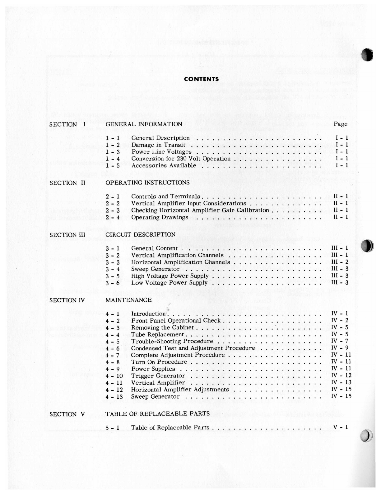
CONTENTS
SECTION
SECTION I1 OPERATING INSTRUCTIONS
SECTION
SECTION IV MAINTENANCE
111
I
GENERAL INFORMATION Page
1
.
1
General Description
1
.
2
Damage in Transit
1
.
3
Power Line Voltages
1
.
4
Conversion for 230 Volt
1
.
5
Accessories Available
2
.
1
Controls and Terminals
2
.
2
.
2 . 4
CIRCUIT DESCRIPTION
3
.
3 . 2
3 . 3
3
.
3 . 5
.
3 6
Vertical Amplifier Input Considerations
2
Checking Horizontal Amplifier Gair Calibration
3
Operating Drawings
1
General Content
Vertical Amplification Channels
Horizontal Amplification Channels
4
Sweep Generator
High Voltage Power supply
Low Voltage Power Supply
..........................
........................
.........................
.
.
0
.
.............
.............
.............
.......................
..............
..........
........................
..................
.................
..........................
.....................
.....................
i
.
i
.
1-1
1-1
1-1
I1 . 1
11
.
I1 . 1
I1
.
111 . 1
111
.
I11
.
111
.
111
.
.
111
1
1
1
1
1
2
3
3
3
SECTION
V
4-1
4-2
4-3
4-4
4-5
4-6
4-7
4-a
4-9
4
.
4
.
4 . 12
.
4
TABLEOFREPLACEABLEPARTS
5
.
Introduction
Front Panel Operational Check
Removing the Cabinet
Tube Replacement.
Trouble-Shooting Procedure
Condensed Test and Adjustment Procedure
Complete Adjustment Procedure
Turn On Procedure
Power Supplies
Trigger Generator
10
Vertical Amplifier
11
Horizontal Amplifier Adjustments
Sweep Generator
13
Table
1
.............................
.........................
.........................
.........................
...........................
.........................
.........................
..........................
of
Replaceable
Parts
...................
....................
............
..................
.................
.....................
IV
.
1
IV
.
2
IV
.
5
IV
.
5
IV
.
7
IV
.
9
IV
.
11
IV . 11
IV
.
11
IV
.
12
IV
.
13
IV
.
15
IV
.
15
V . 1
Page 6
I
I
I
I
I
I
I
I
I
I
I
I
I
I
I
I
I
I
I
I
I
I
I
I
I
I
I
I
I
I
I
I
I
I
I
I
I
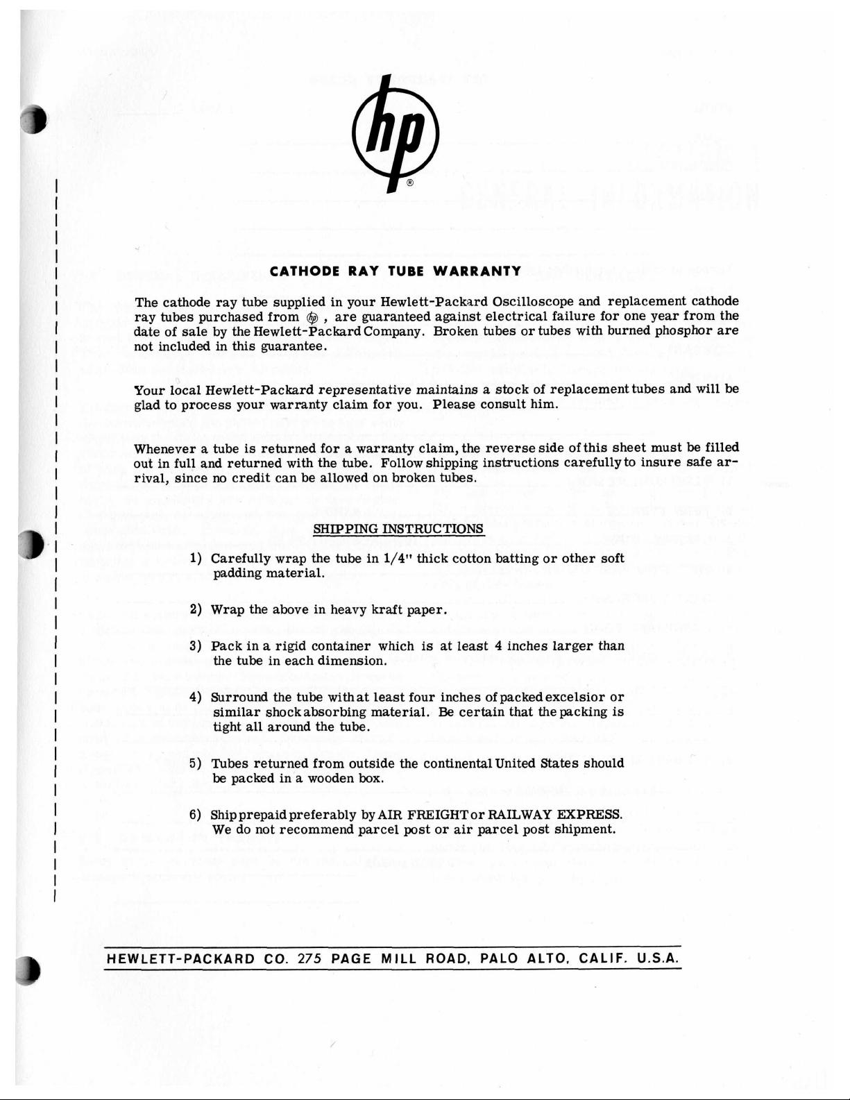
CATHODE RAY TUBE WARRANTY
The cathode ray
ray tubes purchased from
date
of
sale by the Hewlett-PackardCompany. Broken tubes or tubes with burned phosphor
not included in this guarantee.
Your local Hewlett-Packard representative maintains
glad to process your warranty claim for you. Please consult him.
Whenever
out in full and returned with the tube. Follow shipping instructions carefullyto insure safe
rival, since no credit can be allowed on broken tubes.
1)
2)
3)
4)
5)
6)
tube
supplied in your Hewlett-Packard Oscilloscope and replacement cathode
@
,
are guaranteed against electrical failure for one year from the
a
stock of replacement tubes and
a
tube
is
returned for a warranty claim, the reverse side of this sheet must
SHIPPING INSTRUCTIONS
Carefully wrap the
padding material.
Wrap the above in heavy kraft paper.
Pack in a rigid container which
the tube in each dimension.
Surround the tube withat
similar shockabsorbing material.
tight
all
around the
Tubes
Ship prepaid preferably by AIR FREIGHTor RAILWAY EXPRESS.
We do not recommend parcel post or
returned from outside the continental United States should
be
packed in a wooden
tube
in
tube.
box.
1/4"
thick cotton batting or other soft
is
at least 4 inches larger than
least
four inches ofpackedexcelsior or
Be
certain that
air
parcel post shipment.
the
packing
is
be
will
filled
are
be
ar-
HEWLETT-PACKARD
co.
275
PAGE
MILL
ROAD,
PALO ALTO,
CALIF.
U.S.A.
Page 7
FROM:
COMPANY:
ADDRESS:
Person to contact for further inform
NAME
TITLE
COMPANY:
ADDRESS:
To process your claim quickly pl
1)
2)
:
:
@INSTRUMENT MODEL
TUBE TYPE
ease
-
CRT WARRANTY CLAIM
~~~~~~~
enter the information indic
SERIA:
SERIA:
:ated
L
L
below:
I
DATE:
I
I
I
I
I
I
I
I
I
I
I
I
I
I
I
I
I
I
I
I
I
3)
ORIGINALTUBE
4)
YOUR PURCHASE ORDER NO
5)
DATE PURCHASED
6)
PURCHASED FROM
7)
COMPLAINT: (Please describe nature
~~~
8)
OPERATING CONDITIONS: (Please describe conditions prior to and
REPLACEMEN
of
trouble)
SIGNATURE
r
TUBE
at
time of failure
I
‘9
Page 8

Model 122A Sect. I Page
1
SECTION
GENERAL INFORMATION
1-1 GENERAL DESCRIPTION 1-3 POWER LINE VOLTAGES
The Model 122A
cathode-ray oscilloscope. It has accurately
brated input sensitivity and sweep-speed ranges.
This oscilloscope features dc-coupled differential
amplifiers and dual-trace operation.
Differential amplifiers
the common-mode (in-phase) part
amplifying the differential (out-of-phase) part. For
instance, they
plifying the desired signal. In addition, using differential amplifiers has other advantages. Normally dc amplifiers are difficult
Changes such as aging and changes of potentials
cause
the common-mode type and
ferential amplifiers. Thus differential amplifiers
are also used
this drift. However, these changes are of
is
a dc
to
200 kc dual-trace
are
useful since they reject
of
the input
will
reject hum pick-up while am-
to
are
rejected by dif-
to
stabilize dc amplifiers.
cali-
while
keep stable.
This instrument
inal 115 or
operate satisfactorily over a
the nominal value,
130/260 volts
normally high line voltage
line voltage
127 volts.
1-4 CONVERSION FOR
The instrument can be converted from 115 v
230
v operation by reconnecting the power transformer dual primary windings as follows: Remove
the instrument from the cabinet by removing the
two large
the instrument from the cabinet by pushing on the
rear
screws
of
the chassis.
is
designed to operate from a nom-
230
volt
source.
i.e.
103-127 volts. Operationat
will
damage the instrument. If ab-
to
be certain
from the rear
The instrument
*lo%
is
suspected monitor the
it
does not exceed
230
VOLT OPERATION
of
the cabinet. Push
1
will
variation from
to
Dual-trace operation
switch.
at the same time. The two signals may be viewed
either alternately during consecutive sweeps
chopped on each sweep. Chopped operation involves
switching rapidly between the
both appear to be traced simultaneously. The most
useful type
upon the frequencies involved. Generally, chopped
operation
signals may
difference
1-2 DAMAGE
Refer
damage
This
permits observation of
of
presentation in each
is
used with low frequency signals. These
also
(B-A)
to
the warranty page in this manual
is
apparent upon receipt.
is
obtained with an electronic
two
signals
or
two
signals
case
be viewed separately or with their
displayed on the screen.
IN
TRANSIT
will
so
that
depend
if
any
Locate the
next
to
minals on each side
ing the windings in parallel. Remove these jumpers.
Connect an insulated jumper between the second
and fourth terminals, connecting the windings in
series.
Schematic
blow fuse with a 1.0 amp slow-blow fuse.
1-5 ACCESSORIES AVAILABLE
An AC-83 Viewing
is
This
shade the
ambient light conditions. It
lower
power
the power transformer. The twoouter
Refer
for
a face-fitting moulded rubber hood used
face
beam intensity setting.
supply terminal strip situated
are
jumpered together connect-
to
the Low Voltage
details. Replace the 2.0 amp slow-
Hood
is
available
of
the cathode-ray tube under high
will
Power
at
extra cost.
permit the useof
ter-
Supply
to
Page 9

Sect.
11
Page
0
e
c
Y
VI
Model
122A
c
I
I
I
\\
\\
\\
\
I
\
I
I
I
I
I
E
c
C
2
Y
I
I
I II
I
Page 10
122A
Sect. I1 Page
1
P
ONTROLS AND TERMINALS
2-1
briefly shows how
nt. Additional detailed information
VERTICAL AMPLIFIER INPUT
:ONSIDERATIONS
exceed the common-signal voltage limit
my conditions. This limit
Note
rid.
-
c
plus peak ac).
he
attenuators are used the voltage to the
brminals may
the
attenuation as follows:
to
operate the in-
is
*3
that this
be
TABLE
is
the sum of
increased by the amount of
2-1
is
given
volts on the
all
volt-
SECTION
II
OPERATING INSTRUCTIONS
C. Other Types of Input
Other types of input
balanced input with either dual or single channel
operation
as
with most other types
that
ranges must be observed. Thus the commonsignal limit
since there
red input terminal and the input grid. The
red terminal does not have an attenuator between
it and its input grid.’ Therefore balanced input
with attenuation
channel without external attenuators. However, this
may be accomplished using both channels
paragraph B above and Figure
is
possible
it
may only be used on the
is
*3
is
an attenuator only between the upper
are
possible. For example,
(see
Figure
of
volts. This limitation
is
not possible using only a single
2-4).
However,
input, the limitation
.01
VOLTS/CM
is
necessary
2-3).
lower
(see
Attenuator Setting Common-Signal Limi
0.01
VOLTS/CM
0.1
1
.o
10
NOTE Maximum peak input voltage limit
volts (dc plus peak
ommended ways
fer
to
Figures
cerning connections.
A.
Unbalanced Input
Maximum voltage limit
B. Differential (B-A) Input (see Figure
Maximum voltage limit from each line
as
in table
least
40
VOLTS/CM.
ranges, functions of the controls
2-1.
db with both switches
Rejection
ac).
The following are
of
connecting the oscilloscope. Re-
2-1
to
2-4
for further details con-
(see
Figure
as
in table
Common-signal rejection
is
at least
2-2)
set
volts
*3
30
300
500
is
600
rec-
2-1.
2-3)
to
ground trations that follow.
is
at
on
10
MILLI- model. The location of the controls on the front
30
db on other panel
2-3
CHECKING HORIZONTAL AMPLIFIER
GAIN CALIBRATION
The horizontal amplifier may be calibrated by comparing it with the vertical amplifier. First, calibrate the vertical amplifier as shown in Figure
Set both VERT. and HORIZ. SENSITIVITY switches
to
0.1
VOLTS/CM with VERNIER’S in Cal. Feed
1
an external
zontal input terminals. Adjust the input amplitude
for
a
10
R114,
2-4
Basic operating procedures are shown in the
cabinet model but are the same for the rack mount
for exactly
OPERATING DRAWINGS
is
volt signal into the verticaland hori-
cm high pattern. Set Horiz. Gain Adj.,
10
cm of horizontal deflection.
Directions are given for the
different in the rack mount model but the
are
2-10.
illus-
the same.
Page 11
Sect.
I1
Page
2
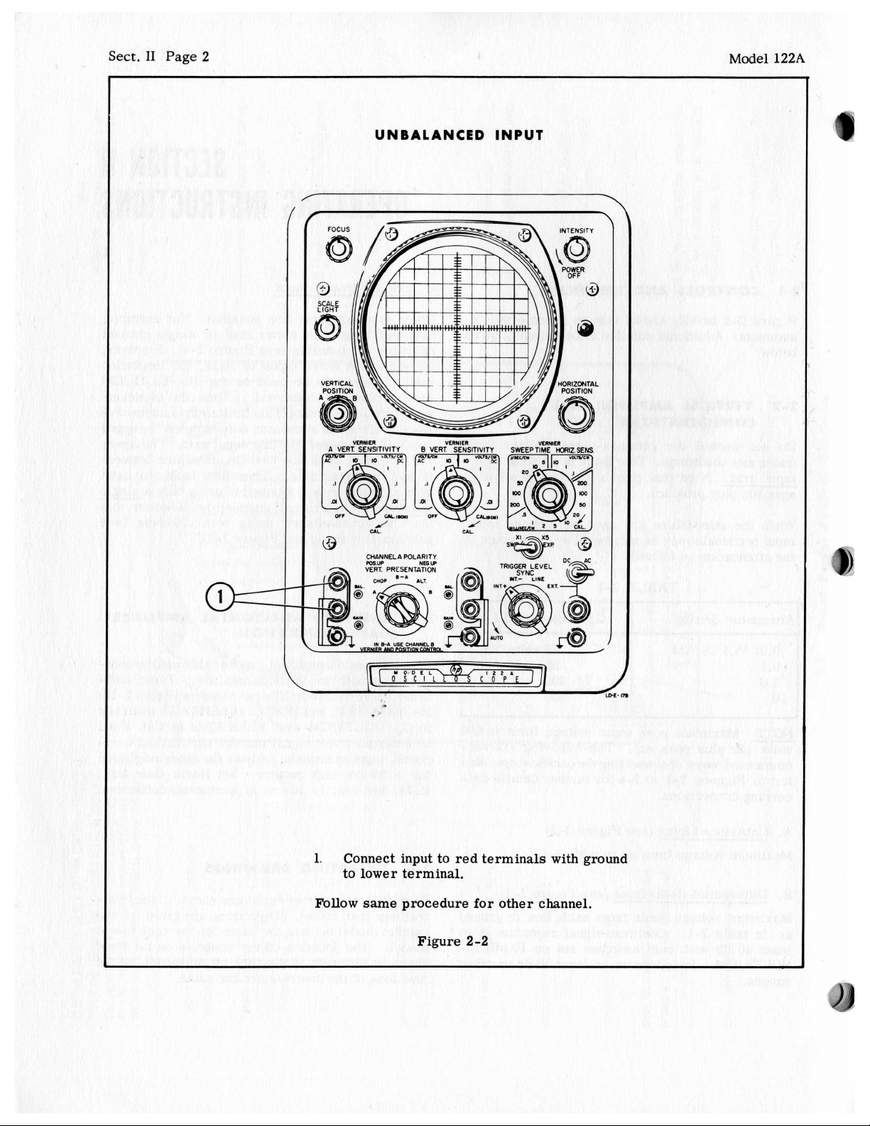
UNBALANCED INPUT
mim
A VERT SENSITIVITY
Model
I
122A
3
\
1.
CHANNELA POLARITY
pos
UP
NE6
up
YODEL
0
SCI
c'i
'P~E
L
J
Connect input to red terminals with ground
to lower terminal.
Follow same procedure for other channel.
Figure
2-2
Page 12
:1
122A
Sect.
I1
Page
3
BALANCED
INPUT
/L
Connect one lead
1.
YODEL
-JI
0
SCI
L
112.
COP
to
top terminal
nel and other lead to other channel.
2.
Set VERT. PRESENTATION to B-A.
3.
Set
both
VERT.
SENSITIVlTY
(same) sensitivity desired
Figure
2-3
of
switches to
(AC
or DC range).
one chan-
Page 13
Sect.
I1
Page
4
Model
122A
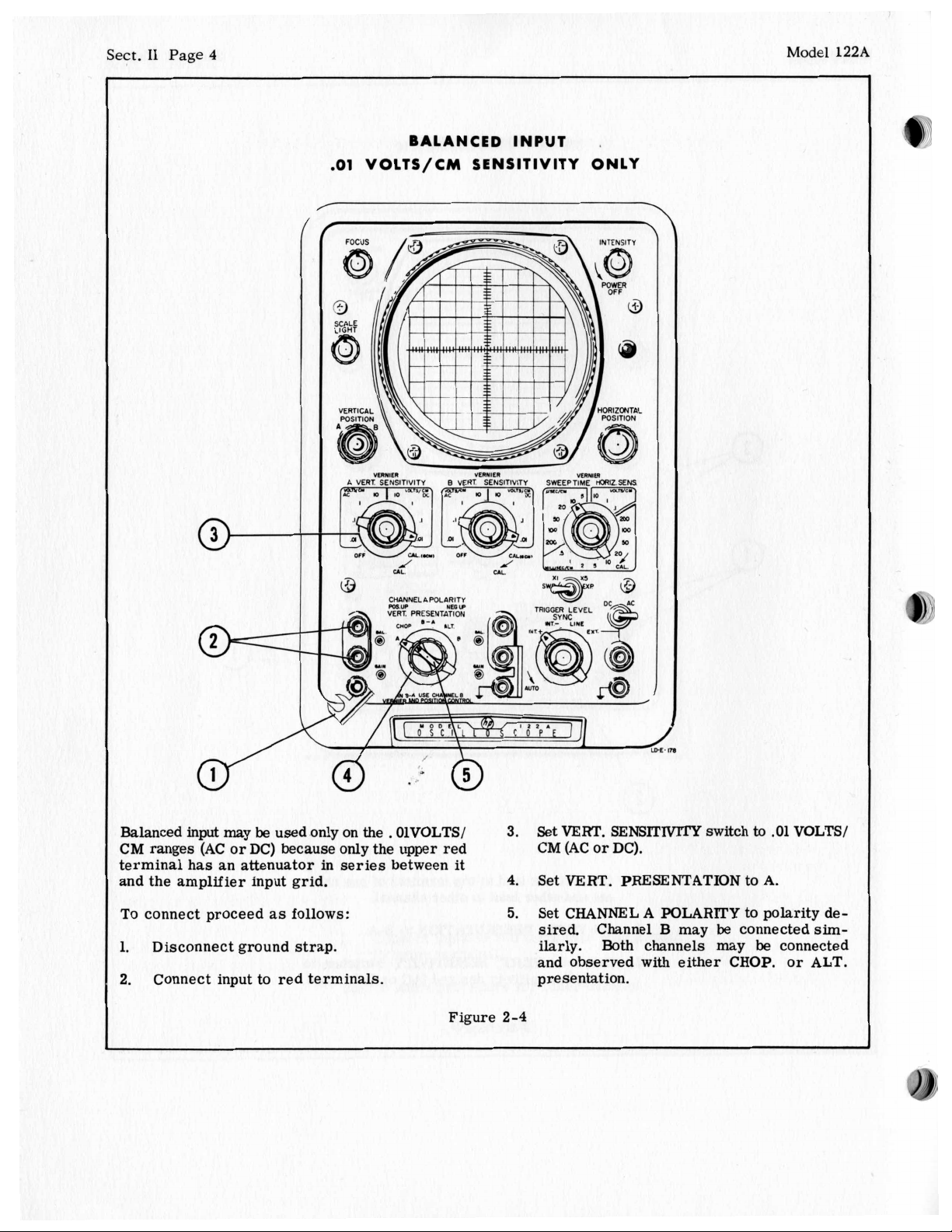
BALANCED INPUT
.01
VOLTS/CM SENSITIVITY ONLY
VLI*ILR
A
VERT SENSITIVITY B VERT SENSITIVITY SWEEPTIME
"EIWlLl
vLI)yDI
,
WIZ
SEM
Balanced input may
CM
ranges (AC
be
used only on
or
DC) because only the upper red
the
.
OlVOLTS/
terminal has an attenuator in series between
and the amplifier input grid.
To
connect proceed
1.
Disconnect ground strap.
Connect input to red terminals.
2.
as
follows:
I
it
Figure
Set
3.
4.
5.
VERT. SENSITMTY
CM
(AC or DC).
Set
VERT. PRESENTATION
Set
CHANNEL
sired.
A POLARITY
Channel
B
may
ilarly. Both channels may
and observed with either CHOP.
presentation.
2-4
switch
to
to
to polarity de-
be
connected
be
.01
VOLTS/
A.
connected
or
sim-
ALT.
Page 14
Model
122A
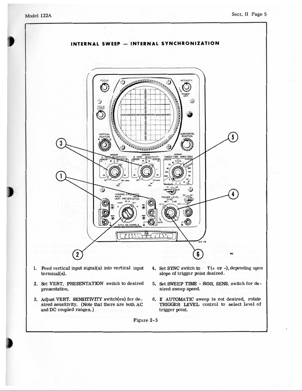
INTERNAL SWEEP - INTERNAL SYNCHRONIZATION
Sect.
I1
Page
5
1.
Feed vertical input signal(s) into vertical input
terminal(s).
2.
Set
VERT. PRESENTATION
presentation.
3.
Adjust VERT. SENSITIVlTY
sired sensitivity.
and
DC
coupled ranges.
(Note
switch to desired
switch(es) for de-
that
there are
)
both
AC
Figure
4.
Set
slope
5.
Set
sired
6.
E
AUTOMATIC
TRIGGER
trigger point.
2-5
SYNC
switch
of
trigger
SWEEP TIME
sweep speed.
LEVEL
T(+
€€OR
is
control
or
SENS.
not desired, rotate
to
to
point desired.
-
sweep
-),depending upon
switch for de-
select level of
Page 15
Sect.
I1
Page
6
CH
0
PP
ED
0
PER
AT1 0 N
Model
122A
.
.
’-
d
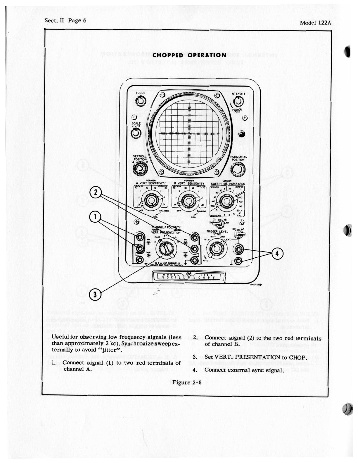
Usefulfor observing low frequency signals (less
than approximately
ternally
1.
to
avoid
Connect signal
channel
A.
2
kc). Synchronize sweep ex-
“Jitter”.
(1)
to
two
red terminals of
Figure
2.
Connect signal
of channel
3.
Set VERT. PRESENTATION
4.
Connect external sync signal.
2-6
B.
(2)
to
the
two
red terminals
to
CHOP.
Page 16
Model
122A
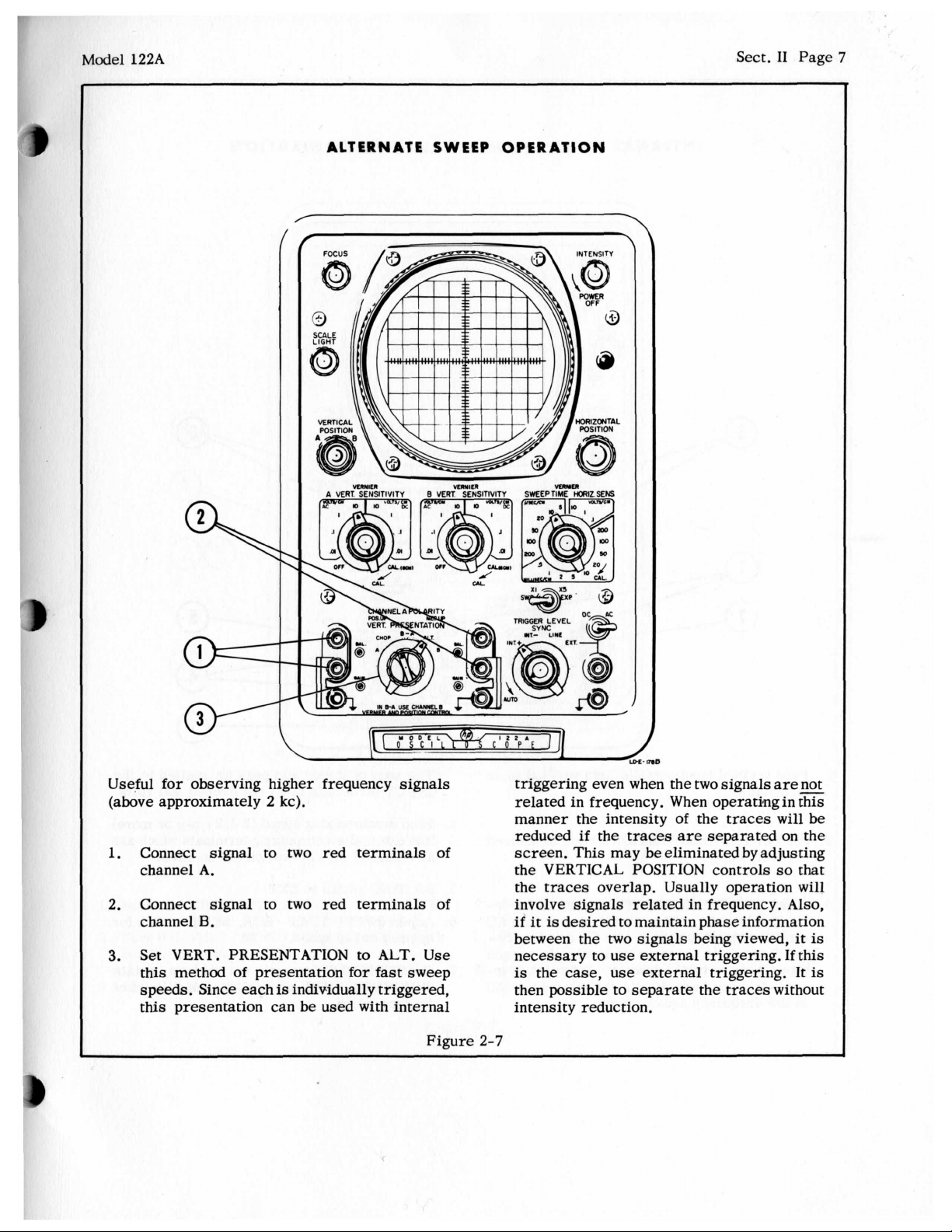
ALTERNATE SWEEP OPERATION
/
Sect.
I1
Page
7
Useful
(above approximately
1.
2.
3.
for
observing higher frequency signals
2
kc).
Connect signal
channel
A.
Connect signal
channel
B.
to
two red terminals
to
two
red terminals
Set VERT. PRESENTATION
this method
speeds. Since each
of
presentation
is
individually triggered,
to
for
ALT.
fast
this presentation can be used with internal
of
of
Use
sweep
Figure
triggering even when the
two
signals
related in frequency. When operating in this
of
manner the intensity
reduced
if
the
traces
the traces
are
separated on the
screen. This may be eliminated by adjusting
the VERTICAL POSITION controls
the
traces
overlap. Usually operation
involve signals related in frequency.
if
it
is
desired to maintain phase information
between the
necessary
is
the
then possible
case,
two
signals being viewed,
to
use
external triggering. If this
use
external triggering. It
to
separate the traces without
intensity reduction.
2-7
ares
will
be
so
that
will
Also,
it
is
is
Page 17
Sect.
I1
Page
8
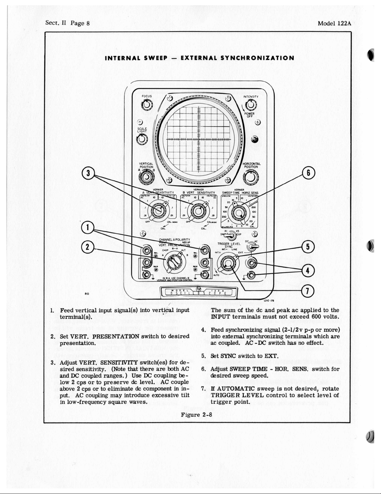
INTERNAL SWEEP - EXTERNAL SYNCHRONIZATION
B
VERT
SENSITIVIT
Model
122A
UL
RO
1.
Feed vertical input signal(s) into vertid input
terminal(
2.
Set
presentation.
3.
Adjust VERT. SENSITIVITY switch(es) for desired sensitivity. (Note
and
low 2 cps
above
put.
in low-frequency square waves.
s).
VERT.
DC
PRESENTATION switch to desired
coupled ranges.
or
to preserve
2
cps or to eliminate dc component in in-
AC
coupling may introduce excessive
I
that
there are both AC
)
Use DC
dc
level. AC couple
coupling
be-
tilt
The sum of the dc and peak ac applied to the
INPUT
4.
Feed synchronizing
into external synchronizing terminals which
ac
5.
Set SYNC switch to EXT.
6.
Adjust SWEEP TIME - HOR.
desired sweep speed.
7.
If
TRIGGER LEVEL control to select level of
trigger point.
terminals must not exceed
signal
coupled.
AUTOMATIC sweep
AC
-DC
switch
600
(2-1/2v p-p or more)
has
no effect.
SENS.
is
not desired, rotate
switch for
volts.
are
Figure 2-8
Page 18
Model
122A
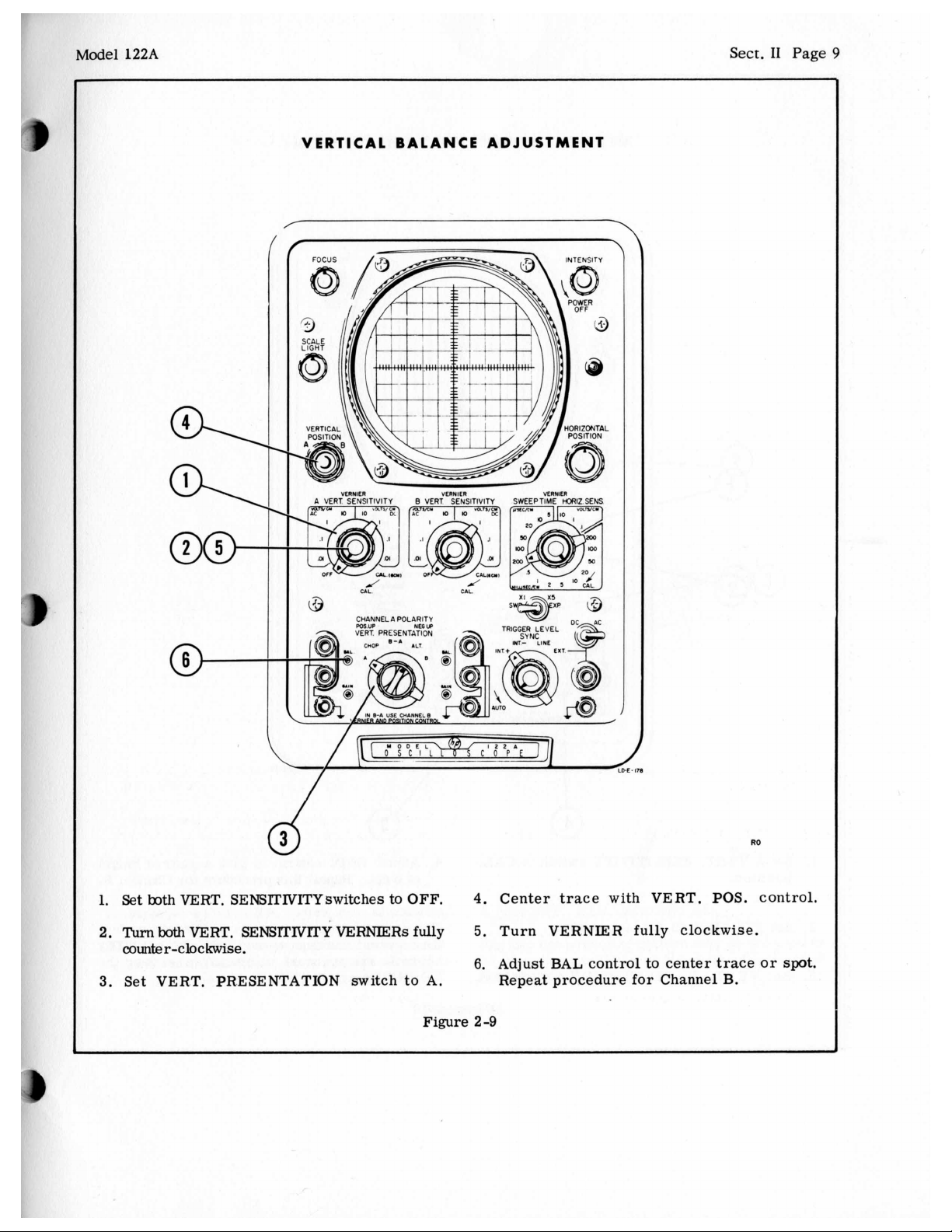
VERTICAL BALANCE ADJUSTMENT
Sect.
I1
Page
9
1.
Set
both
VERT. SENSTI'IVITYswitches to OFF. 4. Center trace with VERT.
2.
TurnbothVERT.
SENSFlWTYVERNIERsfully
5.
Turn VERNIER fully clockwise.
counter-clockwise.
6.
Adjust BAL control
3.
Set VERT. PRESENTATION switch to A. Repeat procedure for Channel B.
Figure
2-9
to
center
POS.
trace
no
control.
or spot.
Page 19
Sect.
I1
Page
10
VERTICAL SENSITIVITY CALIBRATION
Model
122A
mien
A
MRT SENSITIVITY 0 VERT SENSITIVITY
1.
Set A VERT. SENSITIVITY switch
position. of
2.
Set
3.
VERNIER
Set
VERT. PRESENTATION switch
to
CAL. position.
to
vEnmn
CAL.
to
A. VERNIERS
b
4.
Adjust
The vertical amplifier
the engraved markings on
controls
GAIN
6
cm. Repeat
are
accurate within
are
control to give a pattern height
this
in CAL.
M)
procedure for Channel
is
now
the
calibrated
VERT.
+5%
whenever
so
SENSlTIVlTY
B.
that
the
Figure 2-10
Page 20
Mod€
:1
122A
Sect.
I1
Page
11
r
INTERNAL SWEEP MAGNIFICATION
/
A
VERT
WnlcR
SENSITIVITY
e
VERT
"ERllEl
SENSITIVITY
VEwm
SWEEPTIME
KRIZ SENS
1.
Make
sure
SWP.
EXP. switch in in
2.
After obtaining pattern, center the
meters of pattern to
axis
vertical
with
be
HORIZ.
magnified on center
POS.
Xl
position.
two
control.
centi-
Figure 2-11
3.
Set SWP. EXP. switch to X5.
Any two cm portion of pattern may
be
viewed magnified five times by adjustment
HORIZ.
POS.
control.
be
selected
to
of
Page 21
Sect.
I1
Page
12 Model 122A
EXTERNAL HORIZONTAL INPUT
7'
1. Feed horizontal
signal
to horizontal input ter-
CHANNELA POLARITY
VERT PRESENTATION
3.
TRIGGER LEVEL
Set
SWEEP
minds. desired sensitivity.
2.
Set
AC-DC
switch for type of input coupling
This type of input will
desired. Lissajous patterns, etc.
Figure
2-12
TIME
RO
-
HOlUZ.
be
SENS.
switch for
found useful for viewing
Page 22
'1
122A
HORIZONTAL
INTENSITY MODULATION OPERATION
dYICAL
D3
Sect.
I1
Page
13
03
L
REAR
T
VIEW
OF INSTRUMENT.
POSITIVE DEFLECTS UP
I
!
LDY-174
I
AUTION - The deflection plates of the oscil- To intensity modulate with an external signal:
Iscope operate
URN
THE INSTRUMENT OFF BEFORE RE-
at
a
dc potential above ground.
OVING THE COVER PLATE FROM THEDE-
Remove the vertical jumper marked
2.
Connect the external intensity modulation
Z-axis.
1.
LECTION PLATE TERMINALS, TO AVOID signal to these terminals (a negative signal
OMING
IN
CONTACT WITH
HIGH
VOLTAGES.
will
brighten the trace).
Figure
2-13
Page 23
Sect.
I1
Page
14
Model
122A
/
I
I
I
./.----
TOP
-.
OF
CASE
-.--
CONNECTION
HOR/Z.
/wur
-
REAR VIEW OF INSTRUMENT.
TO
DEFLECTION
VERT
iwur
PLATES
-.-.-.
LO-M-169
-.
'\.
\
i
i
i
i
RO
CAUTION
To connect an external signal to the deflection plates:
-
Deflection plates of cathode-ray tube operate
BEFORE REMOVING COVER PLATE FROM DEFLECTION PLATE TERMINALS.
I
I
A.
AC COUPLED
1.
Remove the jumpers going to terminals D1
and D2 for horizontal input and/or D3 and
D4 for
2. Connect
of
3. Connect the
to terminals D3 and
put blocking condensers to D3 and D4.
The POSlTION controls on the 122A
trol the pattern and good focus
vertical
1
megohm 1/2
the jumpers removed in step
input.
vertical
watt
input
D4
resistors in place
blocking
and
the
will
1.
condensers
horizontal in-
will
still
con-
be maintained.
Figure
at
high dc potentials. TURN 122~ OFF
B. DIRECT COUPLED
1.
Remove the jumpers going to terminals D1
and D2 for horizontal input and/or D3 and
D4 for vertical input.
2. Connect leads from the vertical input directly
to D3 and D4 and the lead from the horizontal
input directly to D1 and D2.
POSITION controls
Position voltages
source. Best picture focus
plates are at +275V with respect to
2-14
will
no longer control pattern.
must
be furnished
is
obtained when
122A
by
the signal
chassis.
Page 24
Model 122A Sect.
I1
Page 15
ALIGNING
SCOPE TRACE
WITH
GRATICULE
To align oscilloscope trace with graticule,
move oscilloscope from cabinet; then
1.
Loosen locking clamp with screwdriver.
2.
Adjust fiber lever to adjust position
ray
tube
in
both
radial
and longitudinal direc-
of
cathode-
re-
tions. CAUTION HIGH VOLTAGE. TAKE CARE
NOT TO TOUCH TERMINALS WHICH HAVE A
HIGH POTENTIAL ON THEM.
When the cathode-ray tube is
tighten locking clamp and replace instrument
in cabinet.
Figure 2-15
in
desired position
Page 25
Sect.
I1
Page
16
CONNECTING EXTERNAL CAPACITORS TO EXTEND SWEEP TIME
Model
122A
4
CAPACITORS
-SIDE OF FRONTPANEL
-
TOP OF
rhe slowest calibrated sweep provided
strument
vith the SWEEP TIME VERNIER to af least
;econd/cm or 5 seconds for the
f
you wish a slower sweep the range can be exended indefinitely
apacitors to the sweep circuits.
'0
'abinet.
.
.
Connect external capacitor from point shown
to ground.
is
1/5
second/cm. This can
by
connecting a pair of external
extend the sweep time, remove chassis from
Connect external capacitor across capacitor
shown on SWEEP TIME/CM switch.
FRONT
full
10
IN
PANEL IN RACK-MOUNT MODEL
on
the in-
be
extended
cm sweep.
CABINET
1/2
C A PAC1
MODEL
Values of both capacitors are the same and
be determined by the sweep speed desired.
that the only ranges that these capacitors
affect are the
ranges.
proportion to the amount of capacity added to the
circuit.
calibration
.5,
1,
and 2 seconds/cm respectively.
The capacitor mentioned
must be a high-quality type such
loss of sweep linearity occurs
these specifications
tor
is
connected to the hold-off circuits and does
not require special characteristics.
50,
100
and
200
MICROSECONDS/CM
The extension of the sieep time
Using
2
pfd capacitors
of
the above ranges to approximately
in
is
used. The second capaci-
will
step 1 of this figure
as
if
a
capacitor with
TORS
a0
Note
is
increase the
mylar.
wil:
will
in
No
Figure
2-16
Page 26

Ma
del
122A
Sect.
111
Page
1
D
GENERAL CONTENT
3
-1
Thj
is
section contains a description
of
the Model 122A Oscilloscope. The material in
this
3
section
!
Vertical Amplification Channels
3-2
i
Horizontal Amplification Channel
3-3
.
Sweep Generator
3-4
I
High Voltage
3-5
I
Low Voltage Power Supply
3-0
I
3-1
Bot
.h channels
wil:
1
be given. The vertical amplifier receives
the
input signal, amplifies
def:
lection plates. It provides attenuation
inpi
ut signal, determines the vertical position
the
spot on the screen, and supplies a signal
intc
xnal synchronization. The signal comes into
the
input terminals and
the VERT. SENSITIVITY switch. If the switch
of
1
is
<
3n an AC range the signal goes through a capa-
citc
)r.
s
directly
goe
:e
thrc
str;
light-through range, an
inpi
it grid
CAI
L.
position the calibrator output
the
vertical
nected
con
neo
n-lamp relaxation oscillator.
Ver
.tical Amplifiers
-
!
vertical amplifiers consist
The
cha
nnels of amplification,
witching multivibrator, and
a
s\
:h vertical amplifier
Eac
pled differential amplifiers in cascade. The
cou:
inpi
it
amplifier in each channel has the BAL. control
ween
is
as
follows:
Power
VERTICAL AMPLIFICATION CHANNELS
are
similar
If the switch
to
the attenuator.
frequency - compensated attenuators,
is
shorted, and a CAL. range. In the
amplifier input and plate voltage
to
the calibrator. The calibrator
its
cathodes. The VERT. SENSITIVITY
Supply
so
it,
anddrives the vertical
is
fed tothe AC-DC section
is
on
a
OFF
a
is
composed of three dc-
of
the operation
only one description
Dc
range the signal
The attenuator has
range where the
is
connected to
of
two identical
switching amplifier,
a
trigger amplifier.
SECTION
C
I
R
C
U
IT
DES
VERNIER and the GAIN control
plates
and output amplifier in each channel have plate-to-
grid neutralization. The VERTICAL POSITION
control
plifiers.
the switching amplifiers since the cathode current
for
ing amplifiers. The switching amplifiers in turn
are
The VERT. PRESENTATION switch
type
A
The locked state
ENTATION switch
of
the
for
is
that the multivibrator can be locked in either of
of
two
The other channel in each
the B-A position Channel B
ALT.
The bi-stable
ENTATION switch
a
stable in either
when operating in the ALT. position, Channel
off
received from the sweep. Then Channel
is
on and Channel B
a
repetitive and occurs at the end of each sweep.
CHOP
In the CHOP. position the multivibrator
The circuit
at
position, the
tween the
B-A
-
In the B-A position the signal fromchannel B input
is
of
the input amplifier. The secondamplifier
is
between the cathodes of the second am-
The output amplifiers
the output amplifiers
controlled by the switching multivibrator.
of
vertical amplifier operation as
or
B
is
possible states (Channel A on or Channel B on).
state
of
and Channel
an approximately
two
fed directly into the channel B amplifier. The
B
is
a
free-running multivibrator running
trace
channels
is
furnished by the switch-
used
when theVERT. PRES-
is
set
to
case
is
is
used when the VERT. PRES-
is
set to ALT. Bi-stable means
two positions.
is
on until a trigger pulse
is
turned off. This action
40
kc
rate.
is
switched back and forth be-
at a 40
C
R
I
PTI
are
between the
are
controlled by
selects
A, B or B-A.
is
biasedoff. In
locked on.
For
A
is
Thus, in the CHOP.
kc
rate.
Ill
0
N
the
follows:
Note
example,
A
is
is
is
turned
is
astable.
Page 27
Sect.
III
Page 2
Model 122A
CHANNEL
A
e+
f
CHANNEL
B
OFF
0
ATTENUATOR
CALIBRATOR
ATT E N U ATOR
Figure
4)
I
(DIFFERENTIAL)
3-1.
(40KC)
8-A
Model 122A Block Diagram
DIFFERENTIAL
AMPLIFIER
3
STAGE
DIFFER ENTIA
AMPLlFl ER
I
I
I
I
I
L
-
--
I
I
I
I
A
input
is
signal from Channel
side of the Channel
output
of
the Channel B amplifier
B
differential amplifier. The
ference between the Channel B and Channel
signal. This
3-3
HORIZONTAL AMPLIFICATION CHANNELS
is
the only signal shown on the screen.
The horizontal amplifier receives an input
either from the horizontal input terminals
fedintothe opposite
is
then the dif-
A
signal
or
from
the internal sweep generator, amplifies the signal,
and drives the horizontal deflection plates.
horizontal amplification channel
tenuation
of
the input signal, magnification of the
also
provides
The
at-
internal sweep, and determines the horizontal position of the
The signal comes into the input terminals and
fed
to
AC position the signal goeb through
If this switch
trace
on the screen.
the AC-DC switch..
is
in the
DC
is
If
this switch
is
a
capacitor.
in the
position the signal goes
straight through. The horizontal input signal then
goes through the horizontal sensitivity section
the SWEEP TIME - HORIZ. SENS. switch.
of
This
switch has a three-position frequency compensated
attenuator.
A
signal
is
fed
into the horizontal amplifier. This
signal may be either the horizontal input signal or
a
sawtooth signal from the sweep generator. The
position of the SWEEP TIME-HORIZ. SENS. switch
will
determine which signal
fier.
The amplifier consists
is
fed into the ampli-
of
two
differential
amplifiers in cascade. Plate-to-grid neutralization
is
used in both stages. The input differential
amplifier,
grid
of
POS.
VlOlA,
is
driven single-ended. The
the undriven tube, VlOlB, goes to the HORIZ.
potentiometer.
Two
potentiometers, HORIZ.
SENS. VERNIER and Horiz. Gain, in the cathode
circuit of
potentiometers
SWEEP TIME-HORIZ. SENS. switch
HORIZ. SENS. ranges.
the SWEEP EXPAND switch
X1
or the X5 resistor legs may
tween the cathodes
tiometer and
between the plates
other differential amplifier, V102.
V102
goes
VlOl
provide gain adjustment. These
are
in the
circuit
only when the
is
in the
In the SWEEPTlME ranges
is
used. 'Either the
be
switched be-
of
V101. A
a
Phase. Adj. condenser
of
V101.
Horiz.
Tube
Bal. poten-
are
connected
VlOl
The
feeds
output of
to the horizontal deflection plates.
an-
Page 28

Model 122A Sect.
111
Page 3
3-4
SWEEP GENERATOR
The sweep generator consists of a trigger generator
and a sawtooth generator. The trigger generator
receives the synchronizing signal, selected by the
SYNC selector, and generates a pulse which
itiates the action of
the
sawtooth generator. The
in-
sawtooth generator then goes through one complete
cycle. It automatically
shuts
itself
off bymeans of
feedback upon completion of one cycle. The sweep
circuit
will
operate again
when
another pulse
is
received from the trigger generator, but only after
a hold-off time during which all of
had time to
delay
is
necessary
return
to
their
quiescent voltages. This
so
that successive waveforms
the
circuits have
will start from the same voltage each time.
Trigger Generator
The trigger generator consists of a synchronizing
circuit and a trigger generator, V201. The
syn-
chronizing circuit receives a signal either from
the
vertical amplifier for internal synchronization
(+
or
-),
from an internal 6.3 volt source for line
the
frequency synchronization, or from
horizontal
input terminals for external synchronization. The
trigger generator converts the signal into a fast,
constant-amplitude pulse for operation of the startstop trigger, V202.
The trigger generator, V201,
with narrow hysteresis limits.
is
a Schmitt Trigger
A
negative signal
starts the action by causing the trigger generator
to change state. This action generates a square
is
wave output. This square wave output
differentiated by L201 into a series of positive and negative pulses. These pulses are fed to the start-
s
top trigger.
Sawtooth Generator
The sawtooth generator consists of a start-stop
trigger, an integrator switch, an integrator, and a
hold-off cathode follower. The pulse from
the
trigger generator controls the start-stop trigger
in
which,
turn, controls the integrator switch.
The integrator switch controls the action of the
integrator. The integrator generates a linear,
rising, voltage. This action
plus
the switching
action of .the integrator switch generates a sawtooth
is
voltage. This sawtooth voltage
fed to the horizontal amplifier and to the hold-off cathode follower.
The output of the hold-off cathode follower
the grid of the start-stop trigger.
keeps the start-stop trigger from triggering
all
the circuits have had time to recover to their
is
fed to
This voltage
until
original quiescent voltage.
Gate Cathode-Follower
Another function of
a positive pulse to unblank
This pulse
is
Normally the voltage applied to the grid
cathode-ray tube cuts
the
sweep
obtained from
off
generator
the
the
start-stop trigger.
the
beam. During
is
cathode-ray tube.
to furnish
of
the
the
time of the sweep operation a positive pulse is applied which overrides
negative voltage and
un-
the
blanks the picture.
3-5
HIGH VOLTAGE POWER SUPPLY
The High Voltage Power Supply consists of a Hartley
Oscillator feeding two separate secondary windings
and rectifiers.
Hartley Oscillator
The Hartley Oscillator consists of a pentode, V302,
and a tapped winding on
the
high-voltage transformer. This circuit oscillates at approximately
100 kc. The high-voltage transformer has two
separate secondaries and feeds two separate recti-
fier tubes. Output of one rectifier, V304,
nected to the grid of
INTENSITY control
ply determines the voltage on
thus
and
ing pulse
the brilliance
is
also direct-coupled to
hence to the grid of
the
from
other rectifier
of the cathode-ray tube. Voltage
supply and fed
into
the
cathode-ray tube. The
in
the
output divider of this sup-
the
CRT control grid
of
the
pattern. The unblank-
this
the
cathode-ray tube. Output
is
connected to
is
taken from
the
input of a two stage dccoupled amplifier. The output of this amplifier
fed back to the screen of
the
proper phase to oppose any change
the
Hartley Oscillator
is
con-
supply and
the
cathode
this
is
in
in
the dc
output of the cathode supply.
The Intensity-Modulation terminals are ac coupled
to
the
voltage
cathode of
input
the
cathode-ray tube. A negative
will
brighten the trace while a positive
voltage of approximately twenty volts will blank the
tube from normal intensity.
3-6
LOW VOLTAGE POWER SUPPLY
The
Low Voltage Power Supply consists of three
regulated supplies, one positive and one negative
and a dc filament
supply.
Positive Voltage Supply
The Positive Voltage supply furnishes
+
380 volts
and +lo0 volts. It consists of a transformer, four
Page 29

Sect.
111
Page
4
silicon rectifiers, a pentode amplifier and a triode
in
regulator
figuration, and a triode cathode-follower. Full
output of the supply
ode-follower drops this down to furnish +lo0 volts.
Neon tube, V315, protects V307B from excessive
cathode-to-grid voltage during warm-up.
Negative Voltage Supply
The Negative Voltage Supply furnishes
and -30
silicon rectifiers, and a
erence tube combination
power supply configuration. The
the usual regulated
is
+380 volts. The output cath-
volts.
It consists
regulator-amplifier-ref-
power
supply con-
-150
of
a transformer, two
in
the usual regulated
-30
volt output
volts
is
Model
used
as
a filament reference voltage and fed to the
the
center tap of
Regulated Filament Supply
This supply furnishes regulated
heaters of the four input tubes
plifier. These tubes,
nected in series-parallel. By supplying this filament voltage from
drift
is
greatly reduced.
The
supply consists of a transformer, a silicon
rectifier, and two pnp transistors. Transistor
is
the
series
emitter follower controlling 4301. Reference voltage
is
obtained from the -150 volt supply.
Hum Balance potentiometer.
+24
volts to the
of
the vertical am-
V1,
2,
and
V4,
a
regulated source vertical trace
element. Transistor
122A
5 are con-
4301
4302
is
an
Page 30

Model
122A
Sect. IV Page
1
SECTION
IV
MAINTENANCE
I-1
INTRODUCTION
This section contains instructions
justing, and trouble-shooting the Model 122A
cilloscope.
The Front Panel Operational Check, paragraph 4-2,
is
a
fast method
instrument. The Trouble-Shooting Procedure,
paragraph 4-5,
section
The Condensed
paragraph 4-6,
basic
Test Procedure, paragraph 4-7,
the condensed
Paragraphs 4-3 and 4-4 contain information on
I
removing the cabinet and replacing tubes.
Schematic Diagrams and the Table
Parts
of
the instrument that
adjustments
are
of
checking the operation
is a rapid means of isolating
Test
and Adjustment Procedure,
is
a
fast
method
of
the instrument. The Complete
test
and adjustment procedure.
located at the end
for
testing, ad-
is
not functioning.
of
checking the
is
an expansion
of
Replaceable
of
this section.
of
Os-
the
a
of
YZE
4
AI
EXTRA DATA
SPECIFICATIONS.
In general, the Model 122A can be divided into
sections with the
located behind the front panel controls for that
section. The
on the top chassis brace. Thematerial that
is
divided into sections according
functions. Each section has
adjustment instructions.
The following
and adjusting the Model 122A Oscilloscope during
manufacture. Equivalent
used for testing purposes.
1) “Reference Oscillator” with frequency range
400 cps
5
millivolts
Wide Range Oscillator.
to
RTICULAR INSTRUMENT. THIS
P.
CANNOT BE CONSIDERED AS
parts
power
test
500 kilocycles, and adjustable output
to
20 volts, such
for
any particular section
supplies
equipment
test
are
in the
rear
and
follows
to
circuit
a
complete
is
used
equipment may be
as
@Model 200CD
for
set
testing
of
of
F
Standard, readily available components
for
manufacture
sible. Special components
from the
source
local
stock
please specify instrument model and serial number
plus the component description and stock number
appearing in the Table
Your
plete
assist
or
repair
ments
SPECIFICATIONS FOR THE @ 122A OSCILLO-
SCOPE ARE GIVEN IN THE FRONT OF THIS
MANUAL. THE SERVICE PROCEDURES THAT
FOLLOW CONTAINEXTRADATATOHELPYOU
@
for
@
representative who maintains a parts
for
your convenience. When ordering
local
facilities
you with any engineering, application,
problems you may have with @instru-
.
of
@
instruments whenever
are
available directly
factory. Perhaps the most convenient
spare
@
or
replacement parts
of
Replaceable
representative
and specially trained personnel
also
maintains com-
are
is
used
pos-
your
parts,
Parts.
to
test,
2) “Reference VTVM” with
to
500 kilocycles frequency range, and 50 milli-
volts
to
60
volts voltage range, suchas the @Model
400H Vacuum Tube
3) “Marker Generator” with frequency range
200 kilocycles
steps and an accuracy
Tektronix 180 Time Mark Generator.
4) “Calibration Generator” furnishing lOOv dc and
100
v
ac
at
400
curacy
erator”
the voltage to 20 millivolts in
uation with an accuracy
cation 23678
meet these specifications.
5)
steps from
Attenuator
of * 0.25%. In addition the “Calibration Gen-
must have an attenuator which
“Adjustable Attenuator” having adjustable db
or
Voltmeter.
to 1 cycle per second in decade
or
1000 cps,
Voltmeter
1
to
110
equivalent.
1%
accuracy, 400 cps
of
*0.3%,
all
voltages with an ac-
a
of
*0.25%. The @ Specifi-
Calibration Generator
db.
Use
such
as
will
reduce
1-2-5 times atten-
an @ Model 350A
of
the
will
Page 31

Sect.
IV
Page
2
6)
“Square Wave Generator” capable of furnishing
square waves or pulses, audio frequencies, such
as
the @Models
4-2
Perform the following procedure whenever there
is
the instrument. This
if
sociated equipment. Always perform
ation Check before attempting instrument adjustment or repair.
For a Proof-of-Performance Check complete the
steps as given and compare the
specifications.
strument
up for at least fifteen minutes.
A.
1)
Figure
2)
shown
function properly,
section of the maintenance procedure before proceeding further.
B.
FRONT PANEL OPERATIONAL CHECK
any question about the proper functioning of
the malfunction
in
ADJUST
CALIBRATION
Check the vertical dc balance as shown in
2-9.
Check the vertical sensitivity calibration as
in
VERTICAL AMPLIFIER SENSITIVITY
211A
and
212A.
will
enable you to determine
is
in
this instrument or as-
this
Oper-
results
All
tests are made with the
the cabinet and the instrument warmed
DC
Figure
BALANCE
2-10.
refer
If these controls donot
to VERTICAL AMPLIFIER
AND
with the
VERTICAL
in-
Model
2)
Connect
tion Generator” to input terminal
trace should
refer
tenance procedure.
3)
Check dc
voltage from the “calibration generator”
As
on.
spot should shift
VERTICAL POSITION
4)
Check the accuracy of the remaining VOLTS/CM
positions.
and gives peak-to-peak and
should produce the deflection listed.
5)
Repeat steps 3 and 4 using the A VERT. SEN-
SITIVITY AC ranges.
6)
Repeat above procedure for channel B.
C. VERTICAL AMPLIFIER BANDWIDTH
1)
Set VERTICAL PRESENTATION to
A
TRIGGER LEVEL to AUTO.
2)
Connect the
minal
“reference vtvm”.
3)
Set “reference oscillator” to 2 kilocycles and
adjust for
“reference vtvm”.
a
0.1
volt
ac
signal from the“Ca1ibra-
The vertical
A.
be
10
cm
*5%
(9.5 - 10.5
to
VERTICAL AMPLIFIER section of main-
response
the voltage
10
Table
by switching a
is
switched
cm
*5%
as
necessary.
4-1
lists the selector positions
off
(9.5 - 10.5
rms
cm).
0.1
and on the CRT
cm). Adjust
voltages which
-
A
VERT. SENSITIVITY to
“reference
A,
and monitor the input voltage with the
10
cm of deflection. Note reading on
oscillator” to input ter-
.01
VOLTS/CM
122A
If
not,
volt dc
off
and
I
d
1)
Set VERTICAL PRESENTATION to
A
VERT. SENSITIVITY to
A
VERT. SENSITIVITY VERNIER
TRIGGER LEVEL maximum counterdockwise
but not in AUTO.
Sensitivity
Volts/cm
.01
A
VOLTS/CM,(DC)
ro
Deflection Voltage Required
cm
.01
.1
1
10
CAL.
+
5%
5
5
5
5
4)
Set “reference oscillator” to
rmS
0.0
1767
0.1767
1.767
17.67
“reference
Set output to previous reading on
The deflection should be at least
down point).
section
If
not, refer toVERTICAL AMPLIFIER
of
maintenance procedure.
Peak/Peak
0.05
0.5
5.0
50.0
200
kilocycles.
7.07
vtvm”.
cm
(3db
4
Page 32

Model 122A
Sect.
IV
Page
3
Repeat above procedure for channel B.
5)
VERTICAL AMPLIFIER COMMON
REJECTION
Set
A
VERT. SENSITIVITY to .01 VOLTS/CM
A
VERT. SENSITIVITY VERNIER to CAL.
SWEEP TIME to
VERT. PRESENTATION to
TRIGGER LEVEL to AUTO.
SYNC to INT
Connect the “reference oscillator” to the chan-
2)
ne1
1
A
input terminal through an “adjustable atten-
tor”
Ual
3)
ma
of
4)
int
Stl
cil
5)
of
E.
terminated with
With “reference oscillator’’ set to 1 kc and
tximum output, switch in attenuation until
deflection
Change input
o
both red input terminals. Remove ground
.ap and connect ground side
lator” to black terminal.
Switch “adjustable attenuator” until
1
cm
inge
least
at
Repeat above procedure for channel B.
VERTICAL AMPLIFIER COMMON-SIGNAL
REJECTION (B-A)
is
displayed.
so
is
again obtained. The external attenuation
is
the common-signal rejection and should
40 db.
0.5
MILLISECONDS/CM
A
600
ohms.
that the same signal
of
\
-
“reference
a
deflection
SIGNAL
1
cm
is
fed
os-
6)
Switch A VERT. SENSITIVITY and B VERT.
SENSITIVITY to 0.1 VOLTS/CM. There should
less
than
10
cm of deflection.
7)
Switch VERT. PRESENTATION to B.
8)
Set the “reference oscillator” to 200 kc, and
5
adjust for
9)
Repeat steps 4, 5 and
as
before.
If the instrument
consult the appropriate part of the VERTICAL
AMPLIFIER section
F. WAL TRACE PRESENTATION
1) Set TRIGGER LEVEL to AUTO.
2) Adjust remaining oscilloscope controls to display the chopped
3)
The A VERT.
chopped trace and
move the other.
4) Set VERT. PRESENTATION to ALT. Thechan-
A
ne1
alternately.
cm of deflection.
Limits
6.
fails
to meet any
of
the maintenance procedure.
SYNC to INT
VERT. PRESENTATION
SWEEP TIME to
A
VERT. SENSITIVITY to OFF
B VERT. SENSITIVITY to OFF
50
of
to
CHOP
MILLISECONDS/CM
trace.
POS
control should move one
B
VERT. POS control should
and channel B
traces
should
are
the same
these limits
be
displayed
be
b
1
A
VERT. SENSITIVITY
B
VERT. SENSITIVITY to
B VERT. SENSITIVITY VERNIER to CAL.
SWEEP TIME to
VERT. PRESENTATION to B
Connect the “reference oscillator” to
2)
tnnel
A
cha
Set “reference
3)
out
put for
Switch VERT. PRESENTATION
4)
:tion should
flec
Set
5)
n
ti01
and channel B input terminals.
5
cm
A&
B VERT. SENSITIVITY to 1 V.
should
be
of
deflection.
be
less
less
0.5
oscillator”
than
to
10
VOLTS/CM
10
VOLTS/CM
MILLISECONDS/CM
to 2 kc and adjust
to
B-A.
than
0.1
cm.
1.0
cm.
both
the
De-
Deflec-
HORIZONTAL AMPLIFIER SENSITIVITY
G.
1) Set HORIZ SENS to
HORIZ SENS VERNIER to CAL
VERT PRESENTATION to
DC-AC (horizontal input coupling) to
2) Connect the “calibration generator”,
1.0
volts 4WPTP to the horizontal input terminals. Adjust the position controls to center the
horizontal
(9.5-
AMPLIFIER section
3)
Check the dc response by switching
dc voltage from the “calibration generator”
and on.
CRT “spot” should shift
VERT. POS.
trace.
10.5
cm). If not,
As
the voltage
as
necessary.
.1
VOLTS/CM
A
The trace should
refer
of
the maintenance procedure.
is
switched
10
be
10
to the HORIZONTAL
off
and on, the
cm
*5%.
set
*5%
a
0.1
Adjust
DC
for
long
volt
off
A
Page 33

Sect. IV Page
4)
Check the accuracy of the remaining VOLTS/CM
positions as given
Sensitivity
Volts/cm
.1
1
4
in
the
following table:
Voltage for 10 ( 5%) cm Deflection
Peak/Peak RMS
1.0 0.3535
10.0 3.535
Model 122A
vertical input.
~
with the
6)
7)
lator” until the pattern goes out of synchronization.
The reading on
0.885 volts or
“reference
Set SYNC switch to EXT.
Decrease the amplitude of the “reference oscil-
Monitor the
vtvm”.
the
“reference vtvm” should be
less.
sine
wave
amplitude
10
H.
HORIZONTAL AMPLIFIER BANDWIDTH
1) Set HORIZ SENS to
TRIGGER LEVEL to AUTO
Connect the “reference oscillator” to the
2)
cilloscope horizontal input terminals. Monitor
the
sine
3) Adjust the remaining oscilloscope controls
display the horizontal trace.
4)
Set the “reference oscillator” to 2 kilocycles
and adjust for 10 cm
on “reference vtvm”.
5) Set “reference oscillator” to
Set output to previous reading on “reference vtvm”.
The deflection should now be at least
down point).
AMPLIFIER section
I.
SWEEP GENERATOR TRIGGERING
1)
Set SYNC to INT
TRIGGER LEVEL to AUTO
A
A
VERT PRESENTATION to
2) Connect the
approximately 0.5
scope vertical input.
3)
Adjust remaining oscilloscope controls to dis-
play a
4)
lator” until the pattern
The pattern should
5)
synchronization terminals and the oscilloscope
few
Decrease the input from the
Connect
I
100.0 35.35
I
.1
VOLTS/CM
os-
wave amplitude with the “reference vtvm”
of
deflection. Note reading
200
kilocycles.
7.07
cm (3 db
If
not,
refer
to the HORIZONTAL
of
the maintenance procedure.
VERT SENSITIVITY to
VERT SENSITIVITY VERNIER to CAL
“reference
v
rms,
400
cycles of signal.
goes
be
0.5 cm high or
“reference
oscillator” to the external
0.1
VOLTS/CM
A
oscillator”, set for
cps, to the oscillo-
“reference
out of synchronization.
oscil-
less.
to
If the oscilloscope fails to meet either check,
to the TRIGGER GENERATOR section of the maintenance procedure.
J.
INTERNAL SWEEP TIME
1
1)
.
2) Connect
to the oscilloscope vertical input. Set “marker
generator” for 1/1,000 sec of a
period.
display the signal
to-peak deflection of
signal should produce 10 cycles
cm of horizontal deflection.
3)
checked using
step. Table 4-2 provides complete information on
selector position, frequency or period of the timing
signal and cycles of the signal produced in 9.5-10.5
cm of horizontal deflection.
does not meet these checks,
GENERATOR section of the maintenance procedure.
K.
1)
2)
to the oscilloscope vertical input. Set “marker
generator” for 1,00O/sec.
Ad just remaining oscilloscope controls to display
the
deflection of
produce 10 cycles
zontal deflection.
SWEEP TIME to
Set
SWEEP TIME VERNIER to CAL
SYNC to INT
TRIGGER LEVEL to AUTO
SWEEP EXPAND to
the
output of the “marker generator”
Adjust remaining oscilloscope controls to
with
a vertically centered peak-
4
Each step of the SWEEP TIME/CM selector
the
method outlined
EXPANDED SWEEP CALIBRATION
Set SWEEP TIME to 1 MILLISECONDS/CM
SWEEP TIME VERNIER to CAL.
SYNC. to INT.
TRIGGER LEVEL to AUTO.
SWEEP EXPAND to
Connect
signal with a vertically centered peak-to-peak
the
output of the “marker generator”
4
to 6 centimeter. This signal should
in
10 (55%) centimeters of hori-
MILLISECONDS/CM
X1
1
millisecond
to 6 centimeters. This
in
10 *5% (9.5 - 10.5)
in
the previous
If
your oscilloscope
refer
to the TRIGGER
X1
or
a 1 millisecond period.
refer
is
Page 34

Model
122A
Sect. IV Page
5
SWEEP TIME/CM
Position
*200
MILLISECONDS
100
MILLISECONDS
50
MILLISECONDS
20
MILLISECONDS
10
MILLISECONDS
5
MILLISECONDS
2
MILLISECONDS
1.
MILLISECONDS
.5
MILLISECONDS
200
MICROSECONDS
100
MICROSECONDS
50
MICROSECONDS
20
MICROSECONDS
TABLE
Frequency
1
10
10
10
100
100
100
1,OOO
1,000
1,OOO
10
10
10
4-2.
SWEEP TIME ACCURACY
Timing Signal
cycle
cycles
cycles
cycles
cycles
cycles
cycles
cycles
cycles
cycles
kilocycles
kilocycles
kilocycles
Period
1
second
100
milliseconds
100
milliseconds
100
milliseconds
10
milliseconds
10
milliseconds
10
milliseconds
1
millisecond
1
millisecond
1
millisecond
100
microseconds
100
microseconds
100
microseconds
Cycles Produced in
9.5
to
10.5
cm
2
10
5
2
10
5
2
10
5
2
10
5
2
10
MICROSECONDS
5
MICROSECONDS
*
Use
DC
input coupling
3)
Set SWEEP EXPAND switch
plete
cycles should now appear in
neters
4-3
Disconnect power cord and remove
screws on the
front panel
3ut
[f
moved, dangerous voltages
of
horizontal deflection.
REMOVING THE CABINET
rear
screws.
of
cabinet.
the instrument
is
to
avoid degrading input signal.
of
cabinet.
Slide oscilloscope forward
CAUTION
operated with the cabinet
are
100
100
to
X5.
10
Do
not remove any
exposed. Take
kilocycles
kilocycles
Two
com-
(fig)
centi-
two
large
re-
10
microseconds
10
microseconds
adequate safety precautions, especially when working around the cathode-ray tube terminals and the
power
4-4
In many
rected by replacing a weak
fore
ment, check the tubes. Adjustments that
in an attempt
will often complicate the
It
rather than by use
supplies.
TUBE REPLACEMENT
cases
instrument malfunction can
changing the setting
to
compensate
is
good practice
to
of
check
a
10
5
or
defective tube. Be-
of
any internal adjust-
for a defective tube
repair
problem.
tubes
“tube
by substitution
checker”. The
be
are
cor-
made
Page 35

Sect. IV Page 6
Model 122A
results obtained from the "tube
misleading. Before removing
that
if
the tube
same socket. Replace only tubes proved to be which should
weak or defective. replaced.
CIRCUIT
REFERENCE
I
4301
4302
is
good it can
TABLE 4-3.
v1
v2
v3
v4
v5
V6
v7
V8
v9
VlOl
v102
v201
v202
V203
V204
v205
V301
V302
V303
&
V304
V305
V306
V307
V308
V309
V310
checker"
a
tube, mark it
be
returned to the The following table lists the tests and adjustments
TUBE
TUBE OR TRANSISTOR
TYPE
CTPl113 Regulator
2N383 Amplifier
12AU7 Vert. Input Amp.
12AU7 Vert. Amp.
6DJS/ECC88 Output Amp.
12AU7 Vert. Input Amp.
12AU7 Vert. Amp.
6DJ8/ECC88 Output Amp.
6DJ8/ECC88 Switching Amp.
12AU7 Switching Multivibrator
6AU6 Switching Amplifier
6DJ8/ECC88 Horiz. Amp.
12AT7 Output Amplifier
6AN8 Trigger Generator
6U8 Start-Stop Trigger
12AU7 Gate and Hold-off
12AU7 Integrator Switch
6U8 Sawtooth Integrator
12AU7 Amplifier
6AQ5 Oscillator
5642
5AQP- Cathode-Ray
12B4A Regulator
6U8 Amp.- Output
12B4A Regulator
6AU6 Amplifier
5651
AND
Cathode-Follower.
H.
V.
Cathode-Follower
Reference
can be Any tube with corresponding standard EIA (JEDEC)
so
&
TRANSISTOR REPLACEMENT CHART
FUNCTION
characteristics can
Check+ 24 volt power supply output.
Same as 4301.
Check Vertical Balance and Gain.
Same as
Check Vertical Gain and Balance.
Same as
Same as
Same as
None.
None.
None.
Entire Horiz. Amp. test procedure ex-
cept Attenuator Compensation.
Same as V101.
Check Trigger Generator.
Check Sweep Stability Control Adj.
None.
Hum Balance.
None.
Check
Same as V301.
Rectifier
Tube
Same as V301.
See adjustments under
check Vert. and Horiz. Gain.
Check +380 volt
Check+380 and +lo0
Check -150 volt output voltage.
Same as V308.
Same as V308.
be
used as a replacement.
be
performed after the tubes are
TESTS
AND/OR
V1.
V1.
V1.
ADJUSTMENTS
V3.
H.
V.
Power Supply Output.
TURN
power
supply output.
v
output voltages.
ON
and
Page 36

Model
122A
Sect.
IV Page
7
)
4-5
Ci
time
that
w:
is
imp
any inti
only
a
A.
CH:
-
All
ac
ments
cor
and
ti
If the
1)
Che
of the
usually
Check
B. CHI
-
Check
4-9
PC
refer
tc
and
Ta
MENT
C. CHI
-
TROUBLE-SHOOTING PROCEDURE
1
del
122A Oscilloscope
isic
sections
an
be
minimized by following a procedure
ill
isolate
to
Irtant
ernal adjustments. In the majorityof
tube change
I
ECK AC POWER CIRCUIT
power
will
light with the instrument turned on
inected
ubes
will
ck the power line
Ehassis. The cause
be
found in the
silicon
ECK
DC
dc voltages
)WER SUPPLIES. If you replace any tubes
3
Table 4-3 TUBE REPLACEMENT CHART
ble 4-4 CONDENSED TEST AND ADJUST-
PROCEDURE.
ECK HIGH VOLTAGE CIRCUITS
or
the section needing
isolate the problem before changing
will
be
circuits
to
not light:
a
suitable
are
rectifiers,
LOW VOLTAGE CIRCUITS
as
described under paragraph
is
composed
circuits. Repair and
of
repair.
cases,
required.
normal if any tube
power
fuse
of
low
filter
source.
mounted on the
a
blown line fuse can
voltage power supply.
capacitors,
sev-
test
fila-
rear
etc.
The voltage on the cathode and grid
can be most easily measured
on the high voltage transformer assembly on the
top brace
be
removed on the cabinet model only).
It
vacuum tube voltmeter with a high voltage probe,
such
Voltage Multiplier
Measure
with the orange
proximately -2250 volts. If the voltage
value, both the Hartley Oscillator and the
ondary connected
be
assumed
Measure the CRT grid voltage by measuring the
voltage on the green wire going
rectifier.
volts. If this voltage
the Hartley Oscillator and the secondary connected
to
the grid
If either
Hartley Oscillator may
ing properly. If neither voltage
for
the trouble in the Hartley Oscillator. If
only one voltage
cillator and that secondary
erly. Look for trouble in the secondary supply
with the incorrect voltage.
If you replace any
REPLACEMENT CHART and Table 4-4 CONDENSED TEST AND ADJUSTMENT PROCEDURE.
of
the instrument (shield
as
the @Model 410B VTVM with Model 459A
Probe,
this
voltage on the
wire.
to
the cathode
to
be
functioning properly.
This voltage should be -2260
is
are
functioning properly.
of
the above voltages
is
correct, both the Hartley
tubes
at
the
rectifier
will
for
this measurement.
rectifier
This voltage should be ap-
of
the CRT can
to
within these limits, both
are
be
assumed to be function-
is
present, look
are
functioning prop-
refer
to
Table 4-3 TUBE
of
the CRT
tubes
have
Use
terminal
is
of
the other
to
-2325
correct
to
a
this
sec-
the
Os-
If you
focused
control
assume
If
a
sp
horizon
ins ulatc
TURN
CONNE
be
foun
clip lea
This
s
the CR'
control
ray
tub
are able
I
spot with good brilliance by adjusting the
s,
d
to
ot
or
ita1 deflection plates
zd
INSTRUMENT OFF BEFORE MAKING THIS
CTION. Terminals
id
in the
.d short
hould produce
T
screen
.
If not, check the voltage on the cathode-
e
cathode.
to
get a small, round, and sharply
the high voltage power supply can
be
working.
trace
is
clip
not present, short
lead.
circuit
at
DANGER HIGH VOLTAGE1
rear
access
the vertical deflection plates.
a
spot
some setting
of
the CRT with an
for
these plates
hatch. With a second
near the center
of
circuit
the INTENSITY
be
the
will
of
D.
CHECK HORIZONTAL
PLIFIERS
The Horizontal and
tioning properly when
CRT can be moved easily and smoothly by the
horizontal and vertical position controls.
a
spot
is
If
1) Short the horizontal deflection plates together
with an insulated clip lead. DANGER HIGH VOLTAGE1 TURN THE INSTRUMENT
MAKING THIS CONNECTION. Terminals
plates
not visible on the screen:
are
accessible through the
Vertical
a
spot
AND
VERTICAL AM-
Amplifiers
on the
OFF
are
face
BEFORE
rear
for
access
func-
of
the
these
Page 37

Sect. IV Page
8
Model 122A
hatch. If the “short” produces
be
moved by VERT POS
by
a
vertical input, the vertical amplifier
functioning properly.
2) Short the vertical deflection plates together.
If this produces
HORIZ POS control and deflected by
input, the horizontal amplifier
properly.
amplifiers
The
and balanced, and corresponding voltages in each
side
of
the
circuit
the spot on the screen. The settings
balance and position controls
balanced voltages and should
checking an amplifier.
To
check an inoperative amplifier, short
cuit
corresponding points in each
at
ing
the spot does not return to the screen.
ample, in the Horizontal Amplifier,
is
connected together, remove the jumper from
tween the deflection plates and connect it between
the plate (pin
V102A). Work toward the input, shorting gridto-grid, and plate-to-plate until
where the spot
will
appeared and the point where the spot no longer
appears.
E.
the CRT, until a point
on the screen when the deflection plates
be
between the last point where the
CHECK SWEEP GENERATORS
a
in the instrument
must remain balanced to keep
6)
of
V102B and the plate (pin
does
control
spot that can
not appear. The trouble
a
spot
and deflected
be
moved by
a
horizontal
is
functioning
are
direct
coupled
can
introduce un-
be
considered when
stage,
is
reached where
For
if
the spot
a
point
is
reached
that
of
gain,
start-
spot
can
is
cir-
ex-
are
be-
1
of
2)
A
repetitive sweep should
of
position
the generator
step
in the order listed.
Turn the
ling the
voltages
indicated point with an @Model
pedance Vacuum Tube Voltmeter.
3)
Check
by substitution. Always replace the original
if
proper operation
4) Check the setting
by rotating the control through the entire adjustment range.
If the
a.
plete adjustment step
If adjustment does not restore operation,
b.
R228 near the mechanical center
ment range.
Check the setting
5)
Rotate the control through the entire adjustment
range.
the SWEEP TIME/CM
is
inoperative, try
NOTE
-
power
tubes
are
tubes
generator
off
before
discussed in this procedure.
measured between ground and the
V201 through V205, one
is
not
of
Stability Adjustment, R228,
operates at some setting, com-
10,
of
be
obtained in each
selector.
the
following
removing
410B
or
High Im-
at
restored.
describedinTable4-4.
of
the adjust-
Trigger
Sensitivity R247.
instal-
All
a
time
tube
set
If
I
1)
Set A VERT SENSITIVITY
B
VERT SENSITIVITY
VERT. PRESENTATION to
SWEEP EXPAND
SYNC
to
INT
TRIGGER LEVEL
to
to
to
to
X1
AUTO
OFF
OFF
A
.’
If the generator operates at some setting, com-
a.
plete adjustment step
If adjustment does not
b.
R247 near the mechanical center
ment range.
9,
described inTable 4-4.
restore
operation, set
of
the adjust-
Page 38

del
122A
6
CONDENSED TEST AND ADJUSTMENT
PROCEDURE
the basic
test
and adjustments
are
covered
in the following Table
for
instruments that
strument
is
not operating
are
4-4.
This procedure
functioning.
refer
to
Sect.
IV
If
paragraph
Page
is
the in-
4-5.
9
Page 39

EQUIPMENT
REQUIRED
Dc
vtvm with
1%
accuracy.
None
400 cycle Voltage
Calibration
Generator
None
~~
None
400 cycle Voltage
Calibration
Generator
Time Marker
Generator
Oscilloscope with
low capacity probe
PROCEDURE
Measure all low voltage power supply
outputs, should be within the following
limits: -150+2 volts
+100*3 volts
+380*10 volts
+
24
k1
volt
A.
VERT. SENSITIVITY to .01,
VERNIER fully ccw.
B VERT. SENSITIVITY to OFF
HORIZ. SENS. to 10 VOLTS/CM
Rotate VERNIER fully
A
VERT. SENSITIVITY to .01,
cw
VERNIER to CAL
VERT. PRESENTATION to
A
Connect 100 mv p-p from Calibration
Generator to
B
VERT. SENSITIVITY to .01,
(A)
vertical amplifier.
VERNIER to CAL
VERT. PRESENTATION to B
Connect 100 mv p-p from Calibration
Generator to (B) vertical amplifier.
A
VERT. SENSITIVITY
in
CAL
B VERT. SENSITIVITY in CAL and
both VERNIER’S in CAL.
HORIZ SENS to 10 VOLTS/CM,
VERNIER to CAL.,
A
VERT. SENSITIVITY to OFF,
VERT. PRESENTATION to
A.
Turn VERNIER fully ccw.
.1
HORIZ SENS to
VOLTS/CM,
VERNIER to CAL.,
A
VERT. SENS. to OFF,
VERT. PRESENTATION to
A.
Connect 1.0 v p-p from Calibration
Generator to horizontal input.
5
SWEEP TIME to
SWEEP EXPAND to
MILLISECONDS/CM,
X1.
Apply 5 millisecond markers to
vertical input.
Change time markers to
1
MILLISECONDS/
CM and set SWEEP EXPAND to X5.
SWEEP TIME 10 psec/cm.,
SWEEP EXPAND to
X1
Connect probe to pin 1 or 6 of V102.
Adjust sweep start to center of screen.
SWEEP EXPAND to X5. Adjust Sweep-
Start to center of
screen.
Do
not adjust
ADJUST
if
within limits. Check sweep
-
NOTES
Adjust R344 for -150 volts. calibration
-150~ (R268)
is
adjusted.
Adjust spot to center of
screen
with A VERTICAL required.
Repeat as
POSITION control.
Repeat for
Center spot with channel
A
BAL.
A
Adjust channel
Gain (R27)
channel
B.
for 10 cm deflection.
Adjust channel B
Gain
(R47)
for 10 cm deflection.
Adjust Calibrator Set (R356)
for 6.0 cm deflection.
A
Center spot with
(outer) Repeat as
VERT. POS. knob. required.
Center spot with Horiz. Bal.
(R110).
-
Set Horiz. Gain (R114) for
10 cm horiz. deflection.
Adjust trigger level for
stable pattern.
Adjust R107 for marker coincidence with
1
cm graticule
marks.
Adjust R108 for marker coin-
cidence with
1
cm graticule
marks.
Adjust C105 to compensate
fly bac
k.
Adjust C106 to compensate
flyback.
if
Oscilloscope with
1O:l
probe
50
cps to 250 kc
oscillator
AC VTVM
DC
VTVM
SYNC to EXT.,
TRIGGER LEVEL to AUTO.
DC
couple a 250 kc
sine
wave of
.5
v rms
into the EXT. SYNC. input.
to
Couple probe loosely
body of R204
(a 3.6K resistor pin 6 V201)
Disconnect
(-100
all
ext. inputs. Connect VTVM
v
scale) to pin
8
of
V203,
VERT. SENS. to OFF
SWEEP TIME to
.5
MILLISECONDS/CM,
SYNC INT. TRIGGER LEVEL fully ccw
but not in AUTO.
Set trigger sensitivity control Check for stab1
(R247) just clockwise of
the
point where stable triggers
are
obtained.
triggers from
50
cps to 250
with
0.5
v
rms.
kc
Slowly adjust SWEEP STABIL-
until
sweep
ITY (R228)
begins.
Repeat and note voltage just
prior to sweep start.
Set R228 for 2.0 volts more
positive.
Page 40

M
o(
jel
122A
Sect. IV Page
11
4-1
usu
con
test
con
The
mer
tion
cau,
befc
mer
SPE
CIL
MA:
COT
AL'
EX'
CAI
For
low:
VOll
seci
SUP1
recc
adjL
4-a
Per
has
of
SUP1
rhpi
-..-:k upon the correctness
have been made.
1)
to ground. When measured with an @Model 410B
Voltmeter, they should be within
COMPLETE ADJUSTMENT PROCEDURE
ially a particular oscilloscope will not need
or
iplete testing and calibration. Only one
:s
will be needed and they can be done without
ipleting the entire
!
following procedures
ided sequence
I
operation. In general, tubes
se
of trouble and new ones should be tried
ire
making adjustments
its. See paragraph 4-4.
3CIFICATIONS FOR THE
,LOSCOPE ARE GIVEN IN THE FRONT OF THIS
NUAL. THE FOLLOWING TEST PROCEDURE
gTAINS EXTRA CHECKS TO HELP YOU
fZE A PARTICULAR INSTRUMENT. THESE
TRA CHECKS AND THE DATA THEY CONTAIN
VNOT BE CONSIDERED AS SPECIFICATIONS.
'
location
ing procedure,
tage
tion. A fifteen minute warm-up and power
ply output voltage measurements
2mmended before making any other
is
tment
TURN
form this procedure only after repair work
been done on the instrument. The purpose
lis
procedure
tl
Jlies
Measure resistances from the power supplies
of
and Resistance Diagram
.
ON
have been shorted and
test
procedure.
are
listed in a recom-
for a complete
test
and calibra-
are
or
component replace-
@
MODEL 122A
the controls mentioned in the fol-
see
Figures 4-1, 4-2 and the
at
the end of this
are
PROCEDURE
is
to
check that none
to
of
50%
of
the power
serve
as
the repairs that
of the following:
two
the main
OS-
AN-
always
test
a
partial
or
3)
Turn instrument on and measure the output
voltage of the internal
graph 4-9 POWER SUPPLIES). When turning the
oscilloscope on for the
power supply circuit, turn the INTENSITY control
fully counterclockwise before applying power.
ure to follow this precaution may cause permanent
cathode-ray tube damage. If you
a
small, round, and sharply focused spot with good
brilliance by adjusting the controls, the high voltage
power supply can be assumed
properly.
4) If necessary, the high voltage can be measured
and adjusted
Voltage Adjustment,
Astigmatism (R316) controls
tain
a
small, round, and sharply focused spot. If
the high voltage
and Horizontal Amplifier Gain.
5)
If the cathode-ray tube physical position has
been changed, check
Turn TRIGGER LEVEL control fully counterclockwise
to
CROSECONDS/CM. The CRT
parallel with the graticule lines. The CRT
should be placed just behind the
If CRT face and
pattern will result.
4-9
The power supplies in the oscilloscope
tremely stable and will require infrequent adjust-
ment. The output voltages should be measured
with
an @Model 405A
but unnecessary adjustments should be avoided.
POWER SUPPLIES
a
as
in paragraph 4-8. If R308, High
is
AUTO. Set SWEEP TIME switch to
filter
recently calibrated
power
first
is
changed, adjust FOCUS and
changed, recalibrate the
trace
touch, a visible interference
or
412A, at regular intervals
supplies (see para-
time
after
repair in any
Fail-
are
able to
to
be operating
at
low
intensity toob-
Vertical
alignment with bezel.
50
MI-
trace
should be
face
filter
in the bezel.
are
ex-
1%
voltmeter, such
get
as
50K
+
380
volt supply
+
100
-150 12K
+
24 5.5K (Remove V1, 2,
2) Measure resistances
and horizontal input terminals
positions. As
Voltmeter these resistances should
VERT SENSITIVITY
HORIZ SENSITIVITY I 1
measured with an @Model 410B
to
OFF
CAL
ohms
50K
4, and
ground into the vertical
for
=
1
Megohm
=a
=a,
Megohm
all
read:
5
to check)
dc switch
CAUTION
When first turning the oscilloscope on turn the
INTENSITY control fully counterclockwise before
applying power. Failure
can cause permanent cathode-ray tube damage.
to
follow this precaution
------------
1) Turn instrument on and allow at'least 15 minutes for warm-up.
2) Turn the sweep generator off by turning the
SWEEP TIME
CM.
-
HORIZ SENS switch
to
10
VOLTS/
Page 41

Sect.
IV
Page
12
Model 122A
3) Measure power supply output voltages with line
set
to
115
voltage
various voltages appear can
color
wire
will normally
tiometer Low Voltage Set, R344, can
if necessary,
the limits in Table 4-5. If the voltages
limits and
adjust in an attempt
settings.
If adjustment of the
check
ments.
TABLE 4-5. REGULATED POWER SUPPLY
NOMINAL NORMAL
VOLTAGE
-7-
code
pass
all
Sweep Generator and Calibrator adjust-
RIPPLE
-150
+
380
+
100
+
24
With line voltage
c*
In vertical amplifiers.
40
40
v. The points at which the
be
identified by the
given in Table 4-5. The voltages
be
within the limits given. Poten-
be
adjusted,
to
set the
-150
volt supply within
are
steps 4 and 5 that follow,
to
refine the existing control
-150
4
3
mv
set
to
volt supply
COLOR
CODE
Violet
Red
Yellow
White**
115
v.
is
necessary,
VOLTAGE
TOLERANCE*
*
2 volts
*lo
*3
*
1
within
do
not
spot.
and adjust Intensity Limit control, R322,
the CRT
ments
the high voltage control, R308, has been changed.
4-10
The Trigger Generator must
the Vertical and Horizontal Amplifiers. Also,
these amplifiers must be adjusted before the Sawtooth Generator can be adjusted. Check the
Generator
1) Check power supply according
2) Adjust Stability Control, R228.
Connect an @410B (-100 v dc range)
V203. Slowly
counterclockwise until the sweep
ning. Then back control
Take
-78
the
the stability control.
Set
pointer on INTENSITY knob
spot
is
just extinguished. These adjust-
are
usually required only
TRIGGER GENERATOR
as
follows:
Set A VERT SENSITIVITY
B VERT SENSITIVITY
SWEEP TIME
SYNC to INT
TRIGGER
not in AUTO.
VERT PRESENTATION to A
to
LEVEL
rotate
.5
fully counterclockwise but
Stability Control, R228,
if
the setting
be
working to adjust
to
paragraph 4-9.
to
OFF
to
OFF
MILLISECONDS/CM
or
starts
off
until
it
a
voltage reading which should be about
Set
volts.
last
R228 to 2.0 volts more positive than
reading. This
is
the proper setting for
to 9 o’clock
so
that
Trigger
B
to
pin 8
free-run-
just stops.
of
of
4) You may wish
supply voltage
between
should remain within
range.
5) Measure the ripple voltage on the various sup-
plies. They should approximate the values given
in
6) Measure
instructed in paragraph 4-5C.
H.
voltage to -2250 volts. If this adjustment
changed,
amplifier gain.
7)
ASTIGMATISM control, R316, for a small, round,
103
Table
V, Adjustment, can
Adjust FOCUS control
4-5 with the line voltage
recalibrate
to
check regulation of each power
as
the power line voltage
and
127
volts. All regulated voltages
*l%
over this line voltage
cathode-ray tube cathode voltage
If necessary R308,
be
adjusted to
the horizontal and vertical
for
best focus and
at
fs
115
set
varied
volts.
as
this
is
set
3) External
Set
Trigger
SYNC switch
TRIGGER LEVEL
Horizontal AC-DC switch
VERT PRESENTATION control
Trigger
counterclockwise.
Connect
SYNC (right-hand) terminals.
observe the
probe over the body
Increase Trigger Sensitivity
stable
tivity from
should
range.
when the TRIGGER LEVEL control
position--should
a
250 kc sine wave of
square
triggers
50
be
obtained with
Remove the test set-up and check the
Sensitivity
to
EXT
to
AUTO
to
DC
Sensitivity Control, R247, fully
0.7
With an oscilloscope
wave by clipping the oscilloscope
of
R204 (V201A plate resistor).
control R247, until
are
obtained.
cps to 250 kc. Stable triggering
less
be
about 120
Check
than 0.7 v rms over this
*50
cps.
to
A
or
v rms to the
trigger
sensi-
rate
is
in AUTO
B
Page 42

Sect. IV Page
13
Figure
4-11
1)
Turn
counterclockwise and adjust spot to center with
A
VERNIER control fully clockwise and readjust spot
to
until there
is
ter.
2)
VERTICAL AMPLIFIER
Balance Channel
Set VERT PRESENTATION
A
VERT SENSITIVITY
HORIZ. SENSITIVITY
A
VERT. SENSITIVITY VERNIER fully
VERT.
center with BAL control. Repeat this sequence
rotated. Set A VERT.
Balance Channel B
Set VERT. PRESENTATION
POS.
is
Spot should now be on screen.
B VERT. SENSITIVITY
HORIZ. SENS.
A
to
to
to
control. Turn A SENSITIVITY
no movement
of
POS.
control
to
to
10
VOLTS/CM
Left-Side Adjustment Location Diagram
4-1.
A
.01
VOLTS/CM
10
VOLTS/CM
spot
as
VERNIER
to
the cen-
B
to
10
VOLTS/CM
MP-S-408
Using B VERT. SENSITIVITY VERNIER and
VERT.
3)
Feed into channel
volt peak-to-peak signal from
tion Generator
of
Check this setting
Setting
voltages. If not, check power supplies and vertical
amplifier tubes.
4)
POS.
control repeat procedure
Adjust Channel A Gain
Set VERT. PRESENTATION
A
VERT. SENSITIVITY
A
VERT. SENSITIVITY VERNIER to CAL
A
input terminals
(($9
Specification
channel
Adjust Channel B Gain
Set VERT. PRESENTATION
A
to
give exactly
at
127
and
of
GAIN control should
VERT. SENSITIVITY VERNIER
B
of
step
to
A
to
.01
VOLTS/CM
a
100
milli-
a
Voltmeter Calibra-
23678).
10
cm
103
volts line input.
be
to
B
Set GAIN
of
deflection.
same with
to
CAL
all
B
1.
Page 43

Sect. IV Page 14
of
Repeat procedure
controls.
and
5)
Channel B Attenuator Compensation
B VERT. SENSITIVITY to
Set
(E
B VERT. SENSITIVITY VERNIER
SYNC
to
TRIGGER LEVEL
SWEEP TIME
VERT. PRESENTATION
Connect
minals. Adjust
flection. Adjust C13
uator
VERT. SENSITIVITY
input
response.
VOLTS/CM and apply
generator
Switch back through the
and check
5
kc square wave
for
a
flat-topped square wave. Switch
to
give
8 cm deflection. Adjust C16
Switch
to
input. Adjust C18
for
1O:l
step 3 with channel B input
range)
INT
+
to
AUTO.
to
200 $EC/CM
to
channel
level
for
an 8 cm verticalde-
on
channel B vertical atten-
to
1
VOLTS/CM and increase
B
VERT. SENSITIVITY
full
output
four
attenuator pitions
divisions
(should
.1
VOLTS/CM
to
B
B input
of
square wave
for
flat
be
within
to
CAL
ter-
for
flat
to
response.
1%).
B
10
Model 122A
6)
Channel A Attenuator Compensation
Set
A
VERT. SENSITIVITY to
(DC
range)
A
VERT. SENSITIVITY VERNIER
SYNC
to
DIT+
TRIGGER LEVEL to AUTO.
SWEEP TIME
B
VERT. SENSITIVITY
(DC
range)
B
VERT. SENSITIVITY VERNIER
a
200
Apply
channel
erence
PRESENTATION to B-A and adjust C3
attenuator
VERT. SENSITIVITY and B VERT. SENSITIVITY
to
deflection.
Set
SENSITIVITY
a
oscillator"
10
VOLTS/CM and adjust C8
VERT. PRESENTATION to A and A VERT
5
kc
kc sine wave
B
vertical
for
to
square wave
to
200 pSEC/CM
to
input terminals
set
for
20-25 volts. Set VERT.
minimum deflection. Set both
.1
VOLTS/CM
to
channel A input and adjust
.1
VOLTS/CM
to
CAL
to
.1
VOLTS/CM
to
CAL
both channel A and
from
a
"ref-
on
channel
for
minimum
(DC
range). Apply
A
A
C223
C235
C233
C225
C226
L
..
Figure 4-2. Right-Side Adjustment Location Diagram
Page 44

Model 122A Sect. IV Page
level
for
8
cm deflection. Adjust C22 on VERT
PRESENTATION switch for flat response.
7) Calibrator Amplitude
NOTE
Channel
this step.
A
gain should be adjusted
before
doing
------------
Set A VERT SENSITIVITY to CAL
A
VERT SENSITIVITY VERNIER
B VERT SENSITIVITY
B VERT SENSITIVITY VERNIER
VERT PRESENTATION to
TRIGGER LEVEL to AUTO
Adjust Calibrator Set,
vertical deflection.
4-12
1)
Adjust
control. Turn HORIZ SENS VERNIER fully counter
clockwise and readjust position
ontal Balance Adjustment, R110. Turn HORIZ
SENS VERNIER
HORIZ POS control. Repeat until there
movement
is
The
2) Adjust GAIN
Apply
bration Generator (@Specification 23678)
horizontal input terminals. Set Horiz. Gain Ad-
justment, R114,
Check this setting
Setting
voltages. If not, check power supplies and horizontal amplifier
HORIZONTAL
Balance
Set HORIZ SENS switch to
HORIZ SENS VERNIER
B VERT SENSITIVITY
VERT PRESENTATION
spot
to
of
spot when HORIZ SENS VERNIER
rotated. Set HORIZ POS control
spot
should now be on screen.
Set HORlZ. SENS. control
HORIZ. SENS. VERNIER
1.0
v peak-to-peak from a Voltmeter
of
GAIN control should
center
to
for
at
AMPUFIER
of
CAL and center
exactly
high and low line voltages.
tubes.
to
CAL
A
R365,
for
exactly 6 cm
ADJUSTMENTS
10
to
CAL
to
OFF
to
B
screen with HORIZ POS
of
spot with Horiz-
to
.1
to
CAL
10
cm
of
be
to
CAL
to
CAL
VOLTS/CM
spot
with
is
to
center.
VOLTS/CM
Cali-
to
deflection.
same at
no
the
all
3)
Square Wave Response
Set HORIZ. SENS.
HORIZ. SENS. VERNIER
VERT. PRESENTATION
Connect “square wave generator”
vertical input terminals. Apply
to
horizontal input terminals and
to
trigger Sawtooth Generator. Adjust C107
minimum capacity. Adjust CllO
A
wave.
4)
Attenuator Compensation
Set HORIZ. SENS.
Apply
minals and
of
tooth Generator connected
minals. Adjust C233 on SWEEP TIME switch
flat response. Switch HORIZ. SENS. switch
10
VOLTS/CM and adjust C233
Now switch back through the three attenuator ranges
and check
within
5)
Phase Adjustment
Set HORIZ. SENS.
Apply
channel B input terminals, and
input terminals. Adjust amplitude
6
cm
PRESENTATION
of
pattern.
and adjust C44
phase adjustment on
CM ranges
4-13
The
adjusted
be
completed.
1)
X1
Set SWEEP TIME switch
maximum
HORIZ. SENS. VERNIER
5
kc square wave to horizontal input ter-
also
for
1%.
HORIZ. SENS. VERNIER
A
VERT. SENSITIVITY to
A
VERT. SENSITIVlTY VERNIER
B VERT. SENSITIVITY
B VERT. SENSITIVITY VERNIER to CAL
VERT. PRESENTATION
100
kc sine wave
of
deflection along both axes. Switch VERT.
Switch VERT. PRESENTATION
also.
SWEEP GENERATOR
Vertical and Horizontal amplifiers must
before
Calibration
CM
SWEEP EXPAND switch
to
.l
VOLTS/CM
to
CAL
to
B
to
50
kc square wave
use
for
optimum square
of
2% overshoot
to
1
VOLTS/CM
use same signal
to
1O:l
division. Division should
to
.1
VOLTS/CM
is
to
CAL
to
trigger a Saw-
vertical input
for
flat
to
CAL
.1
to
.1
to
A
to
both channel A and
to
the horizontal
to
to
B and adjust C107
for
closure
.1
Sweep Generator Adjustment can
of
pattern.
VOLTS/CM and 1 VOLT/
to
5
MILLISECONDS/
to
X1
channel B
same signal
permitted.
response.
VOLTS/CM
to
VOLTS/CM
give about
for
closure
Check
15
for
ter-
for
to
be
CAL
to
A
be
Page 45

Sect.
IV
Page 16
Model 122A
Apply 100 cps from
to Vertical Input terminals. Adjust TRIGGER
LEVEL control and choose either INT+ or
best pattern.
R107,
other major division on
2) X5 Calibration
Apply
input terminals. Adjust TRIGGER LEVEL control
for
R108,
major division on the graticule.
3) Sweep Attenuator Compensation
Set SWEEP TIME switch to
Set C226 (see Figure 4-2) to mid-value.
50:l probe to the calibrator output of an additional,
monitor, oscilloscope. Compensate the probe.
Attach this probe to pin 2 of
at input to Horizontal Amplifier. Apply
marker pips from a “Marker Generator” to the
Vertical input terminals. Adjust C214
ure
of sawtooth. The flyback should not overshoot
or
4)
Connect 50:l probe to output of Horizohtal Amplifier, pin
sweep to center of screen with HORIZ. POS.
control.
pensation of fly-back of sawtooth. Switch SWEEP
EXPAND switch to X5 and adjust C106
ure
5) Calibrate
so
Set SWEEP EXPAND switch X5
1
kc from “Marker Generator” to Vertical
best
pattern.
so
SWEEP EXPAND switch to
4-4
undershoot the steady-state voltage.
X1
-
X5 Compensation
Set SWEEP EXPAND switch to
4-3) for proper compensation.
Set SdEEP TIME to 50 MILLISECONDS/CM
Adjust
that the markers coincide with every
that the markers coincide with each
in
this
1
or 6 of V102. Position start of
Adjust C105 (see Figure 4-3) for com-
50
a
Time Marker Generator
for
-
X1
Sweep Gain Adjustment,
the
graticule.
Adjust X5 Sweep Gain Adjustment
10
MICROSECONDS/CM
X1
Attach
VlOlA
section)
millisecond Adjustment Control
to
to
view
sawtooth
100
kc
(see
Fig-
compensate fly-back
X1
(see
Fig-
Remove probe.
Apply
minals.
for marker coincidence with every other major
division on the graticule.
6) Calibrate 0.5 millisecond Adjustment Control
Apply
terminals. Adjust C223
coincidence with
graticule.
7) Calibrate 50 MICROSECONDS/CM Adjustment
Apply
terminals. Adjust C225 (see Figure 4-2) for marker
coincidence
graticule.
8)
Apply
Vertical input terminals. Adjust C226
ure
major division on the graticule.
9)
Apply 1 kc
to the Vertical input terminals. Turn the SWEEP
TIME VERNIER down approximately 3:l and tune
to observe hum modulation on thesweep. Switch
SWEEP EXPAND switch to X5. Adjust Hum
ance control, R360, for minimum hum.
10
cps time markers to Vertical input ter-
Adjust
Set SWEEP SPEED to
1
kc time markers to the Vertical input
Control
Set SWEEP SPEED control to 50 MICROSEC-
ONDS/CM
10
Calibrate 5 MICROSECONDS/CM Adjustment
Control
Set SWEEP SPEED switch to
ONDS/CM
100
4-2) for marker coincidence with every other
Hum
Set SWEEP TIME switch to .5 MILLISECOND/
SYNC to
TRIGGER LEVEL control to AUTO
SWEEP EXPAND switch
50
ms Calibrate adjustment, R251,
.5
MILLISECONDS/CM
(see
Figure 4-2) for marker
every
other major marker on the
kc time markers to the Vertical input
with
every
other major division on
5
MICROSEC-
kc from “Marker Generator” to the
CM
(see
the
Fig-
INT
to
X1
sine
wave
from “reference oscillator”
Bal-
Page 46

Sect.
IV
Page
18
Model
'.
\
122A
E
E
m
0
.-
n
c
.-
L
c
I
>
W
C
0
.-
)I
0
4
c
c
:
c
w
3
.I
W
4
I
0
.-
>
n
0
c
t
c
0
n
n
0
0
m
0
0
c
0
.
\.
\,
1
\
.\
.\
'.
L
b?
I
/
L
/
/-
/
,;
'-
/
/'
/
/
(L
u
/
3
/
/*
C
P
t
3
m
.-
Y
Page 47

Model
122A
Sect.
IV
Page
19
\
I
E
e
'f
.I
n
3
e
0
c
n
.I
n
a
I
a
0
0
c
I
0
>
W
e
0
e
0
.I
c
E
0
4
a
e
E
c
n
3
.-
W
<
3
a
.I
>
E
0
c
c
0
m
Page 48

Sect.
IV
Page
20
Model
-L
122A
'-U
::
I
-I
59
-T
--
n
un
-I-
IT
-
h
0
9-
?
as
"N
-IC
3
I
4s
UN
Page 49

Sect.
IV
Page
t
21
P
-b
a
b
+
0-
9
h
E
1
I
0
i;
PPI
I
I
Page 50

Sect.
IV
Page
9
b
9"
c
::
22
Model
122A
L
0
.I
z
I
E"
4
I
0
c
N
N
C
0
N
._
L
0
r
h:
P
f
N
O?
ON
ie
I
@I
'c
0:
Page 51

M2A
Sect.
IV
Page
23
4
Page 52

Sect.
-1V
Page
24
L
k2
r
Model
122A
bi
.-
L
0
I
I
:
.-
c
P
0
i
Y)
s;
P
Page 53

el
122A
Sect.
IV
Page
25
1
0
%
I
h
5?
L
1
a
?
c
d
c
P
Page 54

Sect.
IV
Page
26
Model
122A
INTERNATIONAL
RECTIFIER
CORPORATION
CR30
2"916
...
u-.
29YAC
953
-
:cC332
1000
2N383
EMITTER
FOLLOWER
C322A
a
"
R3SS
27.5K
R3480
'"
AMPLIFIER
R352
R349A
I50
R3498
150
C
a
E-
c
4440
.OlUF
'%?
E
::g
-
R3S4
*
-:
c333
.
5
SVP ,>v5
.
*VI
4*v4
.+
0301
CLEVITE
CTP1113
REGULATOR
-/MY
f:%
REFERENCE
T
*
-SOY
iOIUF
c330
FIL, DETAIL
.:R345
:.2.52M
CY?
.01ALF
R357
0
CALIBRPTOR
SET
mg:;F-J-
f
L
C
CJEOV
CALIERATOR
OUTPUT
VERT. AMI!
-/sob,
REF. DESIGNATORS
C321
-
335
CR3Ol-
307
OS
301
-
305
0301
-
302
R331 - 364
5301
-
303
V306
-
317
UNASSIGNED:
c326.3zn.331
S302
vi11
-
314
-5
6.3YAC
u
6!7VAC
4.5
RE
+
(SEE
t
6.3YAC
1-
Figure
t
4-5
9
low
-/SOY
.
3
3
4.5
Voltage and Filament Supplies
c
~3.0~
V306
-3OV
-/SOY
SlPPLYl
..
V3 V6 VI02 V307 V308
4-11.
t
-1sov
4 -4 4
>VI01 VPOl V202 V203
5 5
-*
..5
4.5
4.5
,
.
4-i
v7
4.5u
4
v9
Page 55

CATHODE RAY TUBE WARRANTY
The cathode ray tube supplied in your Hewlett-Packard Oscilloscope and replacement cathode
ray tubes purchased from
date
of sale
not included in
Your
local Hewlett-Packard representative maintains a stock
glad to process your warranty claim for you.
Whenever
out in
rival, since
by
the
Hewlett-Packard Company. Broken tubes
this
guarantee.
a
tube
is
returned for a warranty claim,
full
and returned with
no
credit can
1)
Carefully wrap the tube in
padding material.
2)
Wrap
the
3)
Pack in a rigid container which
the
tube in each dimension.
@
,
are guaranteed against electrical failure for one year from the
the
tube. Follow shipping instructions carefullyto insure safe
be
allowed on broken tubes.
SHIPPING INSTRUCTIONS
1/4"
above in heavy
kraft
Please
thick cotton batting
paper.
is
at
the
least
consult him.
reverse
4
inches larger than
or
tubes with burned phosphor
of
replacement tubes and will be
side
of
this
sheet
must
or
other soft
be
are
filled
ar-
4)
Surround
similar shockabsorbing material.
tight
5)
Tubes
be
packed in a wooden box.
6)
Ship prepaid preferably by
We
HEWLETT-PACKARD CO.
the
all
around
returned from outside the continental United
do
not recommend parcel post
tube withat
the
275
PAGE MILL ROAD, PAL0 ALTO, CALIF. U.S.A.
tube.
least
four inches ofpackedexcelsior
Be
certain
AIR
FREIGHTor RAILWAY
or
air
that
parcel post shipment.
the packing
States
should
EXPRESS.
or
is
Page 56

CRT WARRANTY CLAIM
FROM: DATE:
NAME
COMPANY:
Person to contact for further information:
TITLE
COMPANY:
ADDRESS:
To process your claim quickly please enter the information indicated below:
1)
2)
3)
:
:
($3
INSTRUMENT MODEL SERIAL
TUBE TYPE SERIAL
OFUGINALTUBE REPLACEMENT TUBE
4)
YOUR PURCHASE ORDER NO.
5)
DATE PURCHASED
6)
PURCHASED FROM
7)
COMPLAINT: (Please describe nature of trouble)
8)
OPERATING CONDITIONS: (Please describe conditions prior to and
SIGNATURE
at
time of failure
-
Page 57

Sect.V Page
1
TABLE
in this instrument, whenever possible. However, special
components may be obtained from your local Hewlett-
or
Packard representative
When ordering parts always include:
from the factory.
OF
REPLACEABLE PARTS
SECTION
V
1.
63
Stock Number.
2.
Complete description of part including circuit reference.
3.
Model number and
strument.
4.
If
part
tion, function, and location of part.
If
there are any corrections for the Table of Replaceable
Parts
sheet
they
at
the front
is
not listed give complete descrip-
will
be listed on an Instruction Manual Change
of
this manual.
serial
number
of
in-
Page 58

Sect. V Page 2
CIRCUlT
REF.
TABLE OF REPLACEABLE PARTS
DESCRIPTION, MFR.
*
&
MFR.
DESIGNATION
@
STOCl
NO.
Model 122A
-
#
c1
c2
c3
c4
c5
C6
c7
C8
c9
c10
Capacitor: fixed, mylar,
0.1 pf *2%, 600 vdcw
Capacitor: fixed, mica,
27 ppf *5%, 300 vdcw
Capacitor: variable, ceramic,
5-25 ppf
Capacitor: fixed, mica,
390 ppf
Capacitor: fixed, mica,
15 ppf
Same
Capacitor: fixed, mica,
3300 ppf
Capacitor: variable, polystyrene,
0.7 - 3 ppf, 350 vdcw
Capacitor: fixed, ceramic,
.002 pf *2Wo,
Capacitor: fixed, ceramic,
.
01
~100/0,
*lo%,
as
C3
pf *20%,250 vdcw
500 VdCW
500 vdcw
*lo%,
1000
500
vdcw
vdcw
Texas Capacitor Co.
16-110
14-78
Z"
13-28
14-65
14-15
14-64
V*
13-37
L*
15-80
L*
15-135
cw4
c11
c
12
C13
C14
C15
C 16
C17
C 18
*
See
#
Total qua
Lid
game
as
C1
3ame
as
C2
as
as
as
as
as
as
used
C3
C4
C5
C3
C7
C8
in
the instrument.
Same
Same
Same
Same
Same
Same
If
Manufacturers Code Letters
ity
For
Replaceable
Pa
s
Table".
Page 59

C"..
le1
IRCUIT
C
REF.
9
c1
122
TABLE OF REPLACEABLE PARTS
r
DESCRIPTION, MFR.
Same as C9
~
_____~
*
i%
MFR. DESIGNATION
@
STOCI
NO.
-
Sect.
V
Page 3
#
Ma
-
-
c2
c2
c2
c2
c
2,
c
21
c21
c
2!
c3
c3:
0
1
2
3A
4,25
6,27
B
9,30
1,32
3,34
Same
as
C10
Capacitor: fixed, mica,
5
wf
*2Wo, 500 vdcw
Capacitor: variable, ceramic,
3
-
12
wf
Capacitor: fixed, electrolytic, 2 sections,
120
If,
40
pf,
450 vdcw
Capacitor: fixed, titanium dioxide,
2.0
wf
*5%,
500 vdcw
Same
as
C7
Capacitor: fixed, ceramic,
.01
pf,
tol.
-0%
+1Ooo/o,
Capacitor: fixed, titanium dioxide,
1.5
ppf
Same
Same
as
as
*2W0,
C24
C7
500
1000 VdCW
Vdcw
V*
L*
cc
DD*
cc*
DD*
*
14-68
13-29
18
-
51HP
15-118
15-43
15-38
2
1
2
3
13
4
c31
c
c31
C3!
c41
c4:
-
*
#
3(
St
TI
5
;,
37
3
J,40
1,42
?e
tal
"Lis1
Same
as
C28
as
22
330
C29
as
C28
as
C5
ppf
*50/0, 500 vdcw
ppf
*lo%,
in
the
500 vdcw
instrument.
Same
Same
Same
Zapacitor: fixed, mica,
Zapacitor: fixed, mica,
3f Manufacturers Code Letters
quantity used
For
ReDlaceable
J*
Z*
Pa
15-116
14-79
:s
Table".
2
2
-
Page 60

Sect. V Page
CIRCUIT
REF.
~~
4
TABLE OF REPLACEABLE PARTS
DESCRIPTION, MFR.
*
&
MFR.
DESIGNATION
@
STOCl
NO.
-
#
Model
122A
c44
c45
thru
C46
c
100
ClOl
c102
C103
C 104
C105
C106
C107
Capacitor: variable, mica,
2 - 25
Same as
These circuit references
not assigned
Capacitor: fixed, paper,
0.1
Capacitor: fixed, titanium dioxide,
2.2
Same as
Same as
Same as
Capacitor: variable, mica,
50 - 380
Same as
Wf,
C21
pf
*100/0, 600
ppf
*lo%, 500
C28
C102
C44
ppf,
C3
175
175
VdCW
vdcw
vdcw
vdcw
QQ*
cc*
DD*
QQ*
13-34
16-1
15-52
13-5
4
2
3
2
C108,109
CllO
Clll
2112
:113
thru
2199
2200
:201
See
11
List
#
Total
quantity used in the instrument.
Same as
Same as
Capacitor: fixed, mica,
iame as
rhese circuit references
Japacitor: fixed, mica,
Japacitor: fixed,
of
Manufacturers Code Letters For ReDlaceable
C102
C106
680
Wf
*100/~,
C28
not assigned
33
ppf
*5%, 300
1.0
wf'fl%,
500
V~CW
vdcw
titanium
500
vdcw
*'
dioxide,
Z*
Z*
DD*
Pa
14-21
5-136
5-102
6
Tablerr.
1
2
1
-
Page 61

Model 122A
~~
CIRCUrr
REF.
TABLE OF REPLACEABLE PARTS
DESCRIPTION, MFR.
*
&
MFR. DESIGNATION
@
STOCE
NO.
-
-
Sect.
V
Page 5
#
c202
C203
C204
C205,206
C207
C208
C209
c210
c211
Capacitor: fixed, paper,
ppf
as
*lm,
C200
*lo%,
+lo%,
*lo%,
220
Same
Capacitor: fixed, mica,
22 ppf *5%, 500 vdcw
Capacitor: fixed, electrolytic,
20 pf, 25 vdcw
Capacitor: fixed,
68 ppf
This circuit reference
not assigned
Capacitor: fixed,
2000 ppf *20%, 1000 vdcw
Capacitor: fixed, mica,
100 ppf
Capacitor: fixed, mica,
100 ppf
600 vdcw
mica,
500 vdcw
ceramic,
500 vdcw
500
vdcw
Radio Materials Corp.
cc*
V*
cc*
V*
V*
V*
16-12
14-69
18-66
14-60
15-80
14-73
14-100
1
1
2
1
1
1
1
c212
C213
C214
C215
C216
C217
C218
C219,220
*
See
#
Total
Same
as
C28
Capacitor: fixed, mica,
820
ppf
*lo%,
Capacitor: variable, mica,
-
150 ppf, 175 VdCW
14
Same
as
C28
This circuit reference
not assigned
Capacitor: fixed, mica,
47 ppf
Same
These circuit references
not assigned
Lis%
if
I&k&a&Fers Code
quantity used
*lo%,
as
C43
in
the instrument.
500 vdcw
500
vdcw
Letters
For
Replaceable
V*
QQ*
V*
Pa
14-28
13-33
14-67
:s
Tableii.
2
1
1
Page 62

Sect. V Page 6
Model 122A
TABLE OF REPLACEABLE PARTS
CIRCUrr
REF.
c221
c222
C223
C224
C225
C226
C227
C228
C229
DESCRIPTION, MFR.
Capacitor: fixed, mylar,
0.2 pf *5%, 200 vdcw
Capacitor: fixed, mylar,
pf
.02
Capacitor: variable, mica,
170
Capacitor: fixed, mylar,
.0018 pf *5%, 200 vdcw
Same as C213
Capacitor: variable, ceramic,
7
Capacitor: fixed, paper,
.22 pf
Capacitor: fixed, paper,
.022 pf
Capacitor: fixed, paper,
2200
*5%, 200 vdcw
-
790
-
45
wf
+lo%,
*lo%,
wf
*lo%,
ppf,
175 VdCW
,500 VdCW
400 vdcw
600
*
WICW
600 vdcw
&
MFR.
DESIGNATION
cw*
cw*
QQ*
cw*
L*
cc*
cc*
cc*
@
STOCl
NO.
16-121
16-120
13-32
16-119
13-1
16-48
16-12
16-22
1
1
1
1
1
1
1
1
C230
C231
C232
C233
C234
C235
C236
C237
*
See List
#
Total quantity useddn the instrument.
Capacitor: fixed, mica,
220 ppf
Capacitor: fixed, mica,
150
Capacitor: fixed, mica,
1500
game as C44
Zapacitor: fixed, mica,
470
Same
Zapacitor: fixed, silver mica,
30 ppf +5%, 500 vdcw
2apacitor: fixed, sflver mica,
150
bf
MKdactuErs Code Letter8 For Replaceable
*lo%,
wf
*lWo,
wf
*2Wo,
wf
as
C44
wf
*5%, 500 vdcw
500 vdcw
500 vdcw
500
500 vdcw
VdCW
14-66
1
V*
14-150
1
V*
,
14-1500
Z*
14-62
1
1
V*
Z*
A*
Parts
15-146
15-31
Table".
1
1
Page 63

.._..
MI
del
:IRcui
REF.
C:
238
C:
299
C:
300
C:
301
C:
302
C:
303
C:
304
122A
DESCRIPTION, MFR.
thri
These circuit references
not assigned
Same
as
ClOl
Same
as
C9
Capacitor: fixed, mica,
390 ppf
This circuit reference
not assigned
Same
as
C5
TABLE OF REPLACEABLE PARTS
*
&
MFR. DESIGNATION
*5%,
500 vdcw
Z4
@
14-43
STOC
NO.
-
-
V
Page
Sect.
#
1
7
C:
10
5
C:
IO6
c3
107
c3
I08
c3
109
c3
10
c3
11
c3
12
c3
13
C314 thru
C320
Capacitor: fixed, tubular,
.Ol
pf
*2%, 400 vdcw
Capacitor: fixed, paper,
3300 pf *2%, 6000 vdcw
Eapacitor: fixed, paper,
ppf
C28
C306
C307
pi
C9
*209b,
+la,
*lwo,
1500
game
as
as
same
3ame
as
2apacitor: fixed, paper,
.051 pf
zapacitor: fixed, paper,
.015
lame
as
'hese circuit references
not assigned
5000
200 vdcw
3000 vdcw
vdcw
cc*
cc*
cc*
Z*
cc
*
6
-
109
6
-94
6-125
6-84
5-126
1
2
2
1
1
3f
#
Total quantity used in the instrument.
Manufacturers Code Letter8 For Replaceable
Pa
'
Tableii.
Page 64

Sect. V Page 8
Model 122A
CIRCUlT
REF.
C321
C322A
C
323
C324
C325
A,
B
C326
C327
C328
TABLE
DESCRIPTION,
Capacitor: fixed, electrolytic,
120 pf, 350 vdcw
Same
as
C23A
Same
as
C28
Capacitor: fixed, electrolytic,
40
pf
,
450 vdcw
Capacitor: fixed, electrolytic, 2 sections,
20 pf/sect., 450 vdcw
This circuit reference
not assigned
Same
as
C28
rhis circuit reference
not assigned
MFR.
*
OF
REPLACEABLE PARTS
&
MFR.
DESIGNATION
cc
cc
cc
*
*
*
@
STOCl
NO.
18-62HP
18-40HP
18-22HP
-
#
1
1
1
C329
C330
2331
2332
2333
2334
2335
2R301
2R302
2R307
2apacitor: fixed, paper,
0.1 pf
Same
rhis circuit reference
not
2apacitor: fixed, electrolytic,
1000
Same asC28
Same
!ame
?ectifier,
thri
?ectifier, silicon: SD500 Audio Devices
*lo%,
as
C28
assigned
wf,
as
C9
as
C28
silicon:
400 VdCW
50 vdcw
lOOV,
,
.
'.
P.LV.
cc*
cc*
AA*
16-35
.8
-
77HP
812-134
12-147
1
1
1
5
See
#
Total
1'
List of Manufacturers Code Letters
quantity used
in
the instrument.
For
Replaceable
Pa
s
Table".
-
Page 65

Model 122A Sect. V Page
9
CIRCUFI:
REF.
DS301
DS302 thri
DS305
F301
J1
52
TABLE
~ ~~ ~~
DESCRIPTION, MFR.
Lamp, incandescent: 6
2 pin base, GE#12
Lamp, incandescent: 6
.15 amp,
Fuse, cartridge: 2 amp, slow-blowfl
1 a (230 v only)
or
Consists
Connector Assembly:
binding post and ground link
Binding post insulator: double, black
Binding post: insulated, black
Binding post: insulated, red
Consists
Connector Assembly:
binding post and ground link
#47
of
of:
OF
REPLACEABLE PARTS
*
&
MFR. DESIGNATION
-
8V,
-
8V,
N*
N*
E*
HP
HP*
HP
HP
HP*
211-78
211-47
211-16
G-76K
*
AC-54A
AC-1OC
*
AC-1OD
*
G-76J
@
STOCE
NO.
#
1
4
1
1
4
3
5
1
53 thru
JlOO
JlOl
L201
L202 thru
L300
L301
P301
Binding post insulator: double, black
Binding post: insulated, black
Binding post: insulated,
t'hese circuit references
not assigned
Zonsists
Binding post insulator: single, black
Binding post: insulated, black
Binding post: insulated, red
:oil,
rhese circuit references
not assigned
:oil,
Power Cord Elec. Cords Co
R.F.:
RF.:
of:
500 ph
200
ph
red
HP
HP
HP
HP
HP*
HP
CG
CG
*
*
*
*
*
*
*
AC
-
54A
AC-1OC
AC-1OD
AC -54D
AC-1OC
AC-1OD
18-37
18-34
312-56
1
1
1
1
I:
See
Y
Total
tf
II
Lis1
quantity used in the instrument.
Manufacturers Code
Letters
For
Redaceable
Pn
:s
Table"
-
.
Page 66

Sect. V Page 10
CIRCUIT
REF.
Q301
DESCRIPTION, MFR.
Transistor: germanium CTP-1113
TABLE OF REPLACEABLE PARTS
@
STOCK
*
&
MFR. DESIGNATION
Clevite
NO.
213-2
-
Model 122A
#
1
Q302
R1
R2
R3
R4
R5
R6
R7
R8
R9
Transistor: germanium TS-6OOC
Resistor: fixed, deposited carbon,
1
megohm
*l%,
1/2
W
Resistor: fixed, composition,
1
megohm *5%, 1/2
W
Resistor: fixed, deposited carbon,
900,000
ohms
*l%,
1/2
W
Resistor: fixed, deposited carbon,
111,000 ohms
*l%,
1/2
W
Resistor: fixed, deposited carbon,
990,000 ohms
*l%,
1/2
W
Resistor: fixed, deposited carbon,
9100 ohms
*l%,
1/2
W
Resistor: fixed, deposited carbon,
1000 ohms
*l%,
1/2
W
Resistor: fixed, composition,
100,000 ohms
Same
as
R1
f100/0,
1/2
W
CB*
NN*
B*
NN*
NN*
NN*
NN*
NN*
B*
113-1
-
1M
33
23-1M-5
33-900K
33-111K
33-990K
33-9.1K
33-1K
23-100K
1
2
3
2
2
2
2
2
4
R
10
R11
R12
R
13
R
14
R15
R
16
See
#
Total quantity used
Same
Same
Same
Same
Same
Same
Same
11
List of Manufacturers Code Letters For Replaceable
as
R2
as
R3
as
R4
as
R5
as
R6
as
R7
as
R8
in
the instrument.
Parts
Table".
Page 67

del
122A
TABLE OF REPLACEABLE PARTS
Sect.
V
Page
11
mcum
REF.
.7,18
.9
!O,
21
!2
13
!4
!5
16
DESCRIPTION,
Resistor: fixed, composition,
100
ohms
Resistor: fixed, composition,
470
ohms
Resistor: fixed, deposited carbon,
59,480
Resistor: fixed, deposited carbon,
80,000
Resistor: variable, composition,
linear taper,
Resistor: variable, Composition,
250,000
Resistor: fixed, composition,
1000
Resistor: fixed, composition,
18,000
ohms
ohms
ohms
ohms
ohms
MFR.
*lo%,
+lo%,
1/2
1/2
*l%,
*l%,
500
*2W0, .25
*lo%,
*lo'%,
W
W
1/2
1
W
ohms
1/2
1/2
*
&
MFR. DESIGNATION
W
*lo%
W
W
W
B*
B*
NN*
NN*
I*
BO*
B*
B*
@
STOCl
NO.
23-100
23-470
33-59.48E
31-80K
210-25
210-239
23-1K
23-18K
#
-
15
3
4
2
2
2
6
4
17
18,29
'0
1
A,
B
2,
33
4,35
6, 37
8
Resistor: variable, composition,
250,000
Same as
Resistor: fixed, deposited carbon,
8700
Resistor: variable, wirewound,
dual concentric,
*lo%,
Resistor: fixed, deposited carbon,
98,000
Resistor: fixed, composition,
16,.000
Same as R17
Resistor: fixed, composition,
22,000
ohms
R17
ohms
2
w
ohms
ohms
ohms
*20%, 1/4
il%,
1
500
*l%, 1 W
*5%,
*5%,
W
W
ohms each
1/2
W
2
W
BO*
NN*
BO*
NN*
B*
B*
210-228
31-8.7K
210-129
31
-98K
13-16K-5
15 - 22K - 5
2
2
1
4
4
2
?e
!'Lis1
otal quantity used in
If
Manufacturers Code Letters For Realaceable
the
instrument.
Pa
s
Table!'.
-
Page 68

Sect. V Page
CIRCUlT
REF.
12
DESCRIPTION,
TABLE OF REPLACEABLE PARTS
($3
STOCl
MFR.
*
8z
MFR. DESIGNATION
NO.
Model
#
122A
R39
R40,41
R42
R43
R44
R45
R46
R47
R48,4
R50,51
Resistor: fixed, composition,
8200
ohms
Same
Same
Same
Same
Same
Same
Same
Same
Same
as
as
as
as
as
as
as
as
as
*lo%, 1
R20
R22
R23
R24
R25
R26
R27
R17
R32
W
24-8.2K
2
R
52
R53
Same
rhis circuit reference
not assigned
R54,55
R56,57
R
58
3
59
360
See Lis1
#
Total quantity used
Same
Same
Same
Same
?esistor: fixed, composition,
18,000
E
Manufacturers Code Letters
as
R30
as
R34
as
R17
as
R39
as
R38
ohms
in
the instrument.
*lo%, 2
W
.
'.
For
Replaceable
B*
Pa
t5-18K
s
Table'?.
1
3
-
Page 69

lode1
122A
CIRCUIT
REF.
TABLE OF REPLACEABLE PARTS
DESCRIPTION, MFR.
*
&
MFR. DESIGNATION
$2
STOCE
NO.
-
Sect.
V
Page
13
#
361
362,63
?64,65
?66,67
?68
?69
3
70
371
372
thru
?
100
3101
Resistor: fixed, composition,
47,000
Resistor: fixed, composition,
24,000
Resistor: fixed, deposited carbon,
1.15
Resistor: fixed, deposited carbon,
2
Resistor: fixed, composition,
270,000
Resistor: fixed, composition,
560,000
Resistor: fixed, composition,
1.5
Resistor: fixed, composition,
56,000
These circuit references
not assigned
Resistor: variable, composition,
linear taper,
ohms
ohms
megohms
megohms
ohms
ohms
megohms
ohms
*lo%, 2
*5%,
1
+l%,
*l%, 1/2
*lo%,
+lo%,
*lo%, 1/2
*lo'%, 1/2
500,000
W
W
1/2
W
1/2
1/2
ohms
W
W
W
W
W
B*
B*
NN*
NN*
B*
B*
B*
B*
G*
25-47K
24 -24K-
5
33-1.15M
33
-2M
23-270K
-
560K
23
23-1.5M
23
-
56K
210-20
1
4
2
3
2
1
3
1
2
?
102
?
103
3
104
1105
?
106
3107
See Lis1
Total quantity used in the instrument.
Resistor: fixed, composition,
120,000
Resistor: fixed, composition,
1
megohm
Same
Same as
Resistor: fixed, composition,
22,000
Resistor: variable, linear taper,
50,000
If
Manufacturers Code Letters
as
ohms
R8
R17
ohms
ohms
*lo%,
*lo%, 1/2
*lo%, 1/2
*20%,
1/3
1/2
W
W
W
W
For
Replaceable
B*
B*
B*
BO*
Pa
23-120K
23-1M
23-22K
210-245
s
Table".
1
9
3
4
Page 70

Sect. V Page 14
CIRCUIT
REF.
DESCRIPTION, MFR.
TABLE OF REPLACEABLE PARTS
@
STOCK
*
€i
MFR. DESIGNATION
NO.
Model 122A
#
R
108
R109
RllO
Rlll
R112
R113
R114
R115
R116
Resistor: variable, linear taper,
1/2
W
W
1/2
1
W
W
W
5000 ohms *200/0, 1/2
Resistor: fixed, compos ition,
2700 ohms
Resistor: variable, linear taper,
2500 ohms, tol. 200/0, 1/2
Resistor: fixed, composition,
12,000 ohms
Resistor: fixed, composition,
100,000 ohms
Resistor: variable, composition, 2 sections,
50,000 ohms +200/0; rear section:
100,000 ohms
(part of S103)
Same
as
Same
as
Same
as
RllO
R112
Rlll
*100/0,
*lo%,
*lo%,
t
20%
BO*
B*
BO*
B*
B*
BO*
210-246
23-2.7K
210-243
23-12K
24-100K
210-226
1
1
2
2
3
2
R117,118
R119
R120
R121
R122
R123
R124
*
See
It
#
Total quantity used
Same
Resistor: fixed, composition,
Resistor: fixed, composition;
Resistor: fixed, composition,
Resistor: fixed, composition,
Same
Same
Lis1
,f
Manufacturers Code Letters
as
R17
30,000 ohms *5%, 2
6800 ohms
6800 ohms
1800 ohms
as
as
*lo%,
*lo%,
*lo%,
R120
R119
in
the instrument.
1/2
2
1/2
W
W
W
W
For
Replaceable
B*
B*
B*
B*
Pa
2
5-30K - 5
23-6800
25-6800
23-1800
8
Table".
2
2
1
1
Page 71

Modi
r
CII
R
-
el
122A
3cum
:EF.
DESCRIPTION,
TABLE
MFR.
OF
REPLACEABLE PARTS
*
&
MFR. DESIGNATION
@
STOCH
NO.
-
Sect.
V
Page 15
#
R12
R
I<
R2(
R 2C
R2C
R2C
R2C
R2C
R2C
R 2C
R2G
!5
19
10
)1
12
)3
14
)5
)6
I7
I8
These circuit references
thru
not assigned
Same as R25
Same
as
R103
Same
as
R17
Same
as
R103
This circuit reference
not assigned
Resistor: fixed, deposited carbon,
83,000
This circuit reference
not assigned
Res istor: fixed, composition,
10,000 ohms
Same
as
ohms
R62
*l%,
&lo%,
1/2
1/2
W
W
NN*
B*
33-83K
23-10K
1
1
-
*
#
R2G
R21
R21
R21
R21
R21
Set
To
19
0
1
2
3
4
3
I'LiSl
tal
quantity
Same
as
R8
Resistor: variable, linear taper,
200,000 ohms, tol. 20%) .25
(not separately replaceable) (part of S202)
Resistor: fixed, composition,
120,000 ohms *5%, 1/2
Resistor: fixed, deposited carbon,
71,560 ohms
Same as R211
Resistor: fixed, composition,
68,000 ohms
fManufsuyersCode Letters
used
in
*l%,
*lo%,
the
instrument.
1/2
1/2
W
W
W
W
For
Replaceable
BO*
B*
NN*
B*
Parts
210-241
23-120K-5
33-71.56K
23-68K
Tableft.
1
2
1
1
Page 72

Sect. V Page 16
CIRCUIT
REF.
R215
This circuit reference
TABLE OF REPLACEABLE PARTS
DESCRIPTION, MFR.
not assigned
*
&E
MFR. DESIGNATION
@
STOCE
NO.
-
-
Model 122A
#
R216
R217
R218
R219,220
R221
R222
R223
R224
R225
R226
Same
as
R26
Same
as
R17
This circuit reference
not assigned
These circuit references
not assigned
Same
as
R112
Resistor: fixed, composition,
47,000 ohms
Same
as
R25
Resistor: fixed, composition,
27,000 ohms
Resistor: fixed, composition,
680,000
Same
as
R60
ohms
+IO%,
+lo%,
+lo%,
112
112
112
W
W
W
B*
B*
B*
23-47K
13-27K
13-680K
5
6
2
R227
R228
R229
R230
R231
R232
:
See Lis
#
Total
Same
as
R224
:
Resistor
10,000 ohms, tol. 30%, 113
Same
Resistor: fixed, composition,
430,000
Resistor: variable, linear taper,
250,000
Resistor: fixed, composition,
330,000
Electrical value adjusted
bf
Manufacturers Code Letters For Replaceable
quantity
used
variable, 1inea;"tape
as
R224
ohms
*5%, 112
ohms,
ohms
in
the
tol. 20%, 114
*lo%,
instrument.
112
W
W
r,
W
W
at
factory
Eo*
B*
BO*
B*
Pa
l10-240
13
/
430K-
!lo-244
t3-330K
8
Table".
5
1
1
1
1
-
Page 73

ode1 122A
CIRCUIT
REF.
TABLE OF REPLACEABLE PARTS
DESCRIPTION, MFR.
*
i3x
MFR. DESIGNATION
@
STOCK
NO.
Sect.
V
Page 17
#
3233
R234
R235
R236
R237
R238
R239
R240
R241
Resistor: fixed, composition,
220,000 ohms
Electrical value adjusted
Resistor: fixed, glass body,
27,000 ohms
Resistor: fixed, composition,
24,000 ohms +5%, 1/2
Resistor: fixed, composition,
160,000 ohms +5%, 1/2
Same
as
R2
Resistor: fixed, composition,
2 megohms
Same
as
Rl9
Same
as
R224
Resistor: fixed, composition,
100,000 ohms
+lo%,
+lo%,
+5%,
+lo%,
4
1/2
1/2
W
W
W
2
W
W
W
at
factory
B*
AB*
B*
B*
B*
B*
13-220K
134-27K
I3
-
24K-
5
13-16OK-5
13-2M-5
!5-100K
1
1
1
1
1
1
R242
R243
R244 thru
Et246
3247
3248
3249
3250
3251
See List
#
Total quantity used in
Resistor: fixed, composition,
820,000 ohms
Same
as
These circuit references
not assigned
Resistor: variable, linear taper,
1000 ohms, to1 20%, 1/2
Same
as
Resistor: fixed, composition,
270,000 ohms +5%, 1/2
Resistor: fixed, composition,
3900
Same
as
3f
Manufacturers Code
R19
R62
ohms
+lo%,
R107
the
&lo%,
1/2
1/2
W
Letters
instrument.
W
W
W
For Replaceable
B*
BO*
B*
B*
PS
!3-820K
10-247
3-270K-5
3-3.9K
s
Table".
2
1
1
1
Page 74

Sect. V Page
18
Model 122A
TABLE OF REPLACEABLE PARTS
CIRCUlT
REF.
R252
R253
R254
*,B
R255,256
R257
R258
R259
R260
DESCRIPTION, MFR.
Same
as
R106
Resistor: fixed, composition,
47,000 ohms
Resistor: fixed, deposited carbon,
3 megohms
Resistor: fixed, deposited carbon,
3 megohms
Same
as
R113
Resistor: fixed, composition,
39,000 ohms
Same
as
R68
Resistor: fixed, deposited carbon,
20,000 ohms
*lo%,
*I%,
*l%,
*lo%,
*l%,
1
1/2
1/2
*
&s
MFR. DESIGNATION
1
W
W
W
1/2
W
W
B"
NN"
NN"
B"
NN'
@
STOCP
NO.
24-47K
31-3M
33-3M
23-39K
33 -20K
-
#
1
1
2
1
1
R261
R262
R263
R264 thru
R299
R300
R301
R302
R303
Same
as
R66
Resistor: fixed, deposited carbon,
200,000 ohms
Resistor: fixed, deposited carbon,
1.8
megohms + 1%,
These circuit references
not assigned
Resistor: fixed, composition,
1000 ohms
Same
as
R25
Same
as
R222
Resistor: fixed, composition,
150,000 ohms
*l%,
*lo%,
*lo%,
1
1/2
1/2
W
W
W
,
.
'-
2
W
NN*
NN*
B*
B*
33-200K
33-1.8M
24-1K
2 5- 150K
I
1
1
1
1
See Lis1
#
Total quantity used
if
Manufacturers Code Letters
in
the instrument.
For
Replaceable
Pa
8
Table".
-
Page 75

cc-
122A
-
WIT
F.
,311
TABLE OF REPLACEABLE PARTS
DESCRIPTION, MFR.
Resistor: fixed, composition,
560,000 ohms
Same
as
R103
Same as R70
Resistor: fixed, composition,
3 megohms *5%, 1/2
Resistor variable, linear taper,
1
megohm, tol. 30%, .25
Resistor: fixed, composition,
4.7 megohms
Resistor: fixed, composition,
5.6 megohms
*lo%,
+lo%,
*lo%,
*
t3z
MFR. DESIGNATION
1
W
W
W
2
W
2
W
B*
B*
BO*
B*
B*
~
@
STOCK
NO.
l4 - 560K
13-3M-5
210-242
25-4.7M
25-5.6M
-
Sect. V Page 19
#
2
1
3
1
2
,315
'thru
Resistor: variable, composition, linear taper,
3.5 megohms
Same
as
R225
Same
as
R224
Same as R107
Resistor: fixed, composition,
56,000 ohms
Resistor: fixed, composition,
2.2 megohms
Resistor: fixed, composition,
8.2 megohms
Same
as
RlOl
Resistor: variable, composition,
200,000 ohms *200/0, 1/4
(not separately replaceable)
k.3096,
*lo%,
*lo%,
*lo%,
1/2
1
1/2
2
W
W
W
W
W
(part
of
S301)
I*
B*
B*
B*
BO*
2
10- 150
14-56K
!3-2.2M
!5-8.2M
!lo-224
1
1
1
3
1
-
Lid
al
quantity
Same as R222
If
Manufacturers Code Letters
used
in
the
instrument.
For
Replaceable
Pa
s
Table".
Page 76

Sect. V Page 20
CIRCUIT
REF.
DESCRIPTION, MFR.
TABLE OF REPLACEABLE PARTS
@
STOCE
*
&
MFR. DESIGNATION
NO.
-
Model 122A
c
#
R325
R326
R327
R328
R329,330
R331,332
R333
R334
R335
R336
Same as R70
This circuit reference
not assigned
Same as R25
Same as R222
These circuit references
not assigned
Same as R103
Same as R304
Resistor: fixed, composition,
470,000 ohms *100/0,
Same
as
R222
Same as R103
1
W
B*
24-470K
1
R337
R338
R339
R340
R341
R342
See "List
1
Total quantity used in the instrument.
Resistor: fixed, wirewound,
3500 ohms
Resistor: fixed, deposited cdrbon,
405,000 ohms
Electrical value adjusted at factory
Resistor: fixed, deposited carbon,
136,700 ohms
Electrical value adjusted at factory
Resistor: fixed, deposited carbon,
200,000 ohms
Resistor: fixed, composition,
22 megohms
Resistor: fixed, composition,
10,000 ohms
of
Manufacturers Code Letters
*lo%,
10
*l%,
*l%,
*l%,
*lo%,
*lo%,
W
1/2.w
1/2
1/2
1/2
2
W
I
W
W
W
For
Replaceable
R*
NN*
NN*
NN*
B*
B*
Pa
Z6
-
102
33 -40 5K
33-136.7K
33-200K
i3-22M
!5-10K
s
Table".
1
1
1
1
1
1
-
Page 77

L_
V
del 122A
Ma
Sect.
TABLE OF REPLACEABLE PARTS
Page 21
-
@
'IRCUIT
C
REF.
-
R:
343
DESCRIPTION, MFR.
Resistor: fixed, deposited carbon,
1.88
megohms
*l%,
*
&
MFR. DESIGNATION
1/2
W
NN*
STOCK
NO.
33-1.88M
-
#
1
R:
R:
R:
R:
R:
R:
R:
R:
R:
R:
344
345
346
347
348
349
350
351
352
353
Same as R308
Resistor: fixed, deposited carbon,
2.52 megohms
Same as R242
Resistor: fixed, composition,
82,000 ohms
Same
as
R60
Resistor: fixed, composition,
150 ohms
Same
as
R26
Resistor:
15,000 ohms
Same
Resistor: fixed, composition,
2.7 ohms
as
fixed,
R103
*l%,
*lo%,
*lo%,
2
composition,
*lo%,
*lo%,
1/2
W
1/2
W
W
1/2
W
1
W
NN*
B*
B*
B*
B*
33-2.52M
23 -82K
25-150
23-15K
24-2.7
2
1
1
1
1
R:
354
355
R:
R:
356
R:
357
R:
358
R:
359
-
See
11
*z
rotal
#:
Resistor: fixed, deposited carbon,
4440 ohms
Resistor: fixed, deposited carbon,
27,500 ohms
Same
as
Same as R345
Resistor fixed, composition,
2.4 megohms
Resistor: fixed, deposited carbon,
500 ohms
List
of
Manufacturers Code Letters For Replaceable
quantity used
*l%,
*l%,
R308
*5%,
*l%,
1/2
in
the instrument.
1/2
1
1/2
W
W
W
W
NN*
NN*
B*
NN*
Parts
33-4.44K
31-27.5K
23-2.4M-E
33-500
Table".
1
1
1
1
-
Page 78

Sect. V Page 22
CIRCUIT
REF.
DESCRIPTION, MFR.
TABLE
OF
REPLACEABLE PARTS
*
&
MFR. DESIGNATION
@
STOCE
NO.
Model 122A
-
#
R360
R361
R362
R363
s1,2
53
54 thru
5100
5101
3102
5103
Resistor: variable,
500 ohms *30%0, 3/10
Resistor: variable, wirewound,
25 ohms
Same as R103
Resistor: fixed, composition,
470,000 ohms
Vertical Attenuator Switch
Assembly: complete
Presentation-Polarity Switch
Assembly: complete
These circuit references
not assigned
Switch, toggle: SPST
Switch, toggle: SPDT
Part
of 5204
*lo%,
linear
2 W (includes S301)
*lo%,
less components
less components
W
1/2
taper,
W
BO*
BO*
B*
HP
*
W*
HP*
W*
D*
D*
210-115
210-188
23-470K
122A-19D
310-251
122A-19B
310-250
310-11
310-12
1
1
1
2
1
1
1
3104 thru
3200
5201
3202
3203
3204
3205 thru
3300
3301
3302
See
It
Total quantity used
These circuit references
not assigned
Sync-Trigger Level Switch Assembly
Switch, trigger-level
(part of R210 and S201)
This circuit reference
not assigned
Sweep Time-Horizontal Sensitivity
Switch Assembly: includes S103
These circuit references
not assigned
Part of R361
This circuit reference
not assigned
Lid
If
Manufacturers Code Letters
in
the instrument.
For
Replaceable
HP*
HP*
Pa
122A-19C
122A- 19A
Ls
Table".
1
1
Page 79

le1 122A
bloc
Sect. V Page 23
-
C!
S3(
T31
T31
v1
v3
v4
V6
V8
v9
v1
Kcurr
REF.
13
01
02
92
25
97
0,ll
TABLE
DESCRIPTION, MFR.
Switch, rotary
l'
ransformer, power
l'ransformer,
rube, electron: 12AU7
rube, electron: 6DJ8/ECC88
Same as V1
Same as V3
Same as V1
rube, electron: 6AU6
Lamp, glow, 1/25
HV
W
*
OF
&
REPLACEABLE PARTS
MFR. DESIGNATION
W*
310-177
HP
*
120A
HP
*
-11A-1
2
N*
12 - 12 AU7
212-6DJ8
212 -6AU6
211-43
zz*
zz*
zz*
1
2 thru
v1
v1
00
v1
01
v1
02
03 thru
v1
v2
00
v2
01
02
v2
v2
03,204
v2
05
v2
06 thru
v2
09
v2
10
These circuit references
not assigned
Same
as
V3
Tube, electron: 12AT7
These circuit references
not assigned
Tube, electron: 6AN8
l'ube, electron: 6U8
Same as V1
Same as V202
These circuit references
not
assigned
Neon, lamp, aged and selected,
blue code
zz*
zz*
zz*
HP*
2 12
-
12AT
212-6AN8
212-6U8
G-84B
7
-
lee ~~Lisl
*S
'otal quantity used
#1
of
Manufacturers Code Letters For Replaceable
in
the instrument.
Parts
Table".
Page 80

Sect. V Page 24
Model 122A
CIRCUIT
REF.
V211 thru
V213
V214
V215 thru
V217
V219 thru
V300
V301
V302
V303,304
V305
TABLE
DESCRIPTION, MFR.
as
Same
Neon, lamp, aged and selected,
Same
These circuit references
Same
Tube, electron: 6AQ5
Tube, electron: 5642
Tube, cathode ray: 5AQP
V10
green code
as
V210
not assigned
as
V1
flat-faced, 5"
OF
*
&
MFR. DESIGNATION
REPLACEABLE PARTS
(8
STOCE
NO.
G
-84D
HP
*
zz*
ZZ*
1
2 - 6AQ 5
2
212
-
5642
212 -5AQF
1,2,7,
11
-
#
1
1
2
1
V306
V307
V308
V309
V310
V311 thru
V314
v315
V316,317
V318 thru
V321,322
Tube, electron: 12B4A
Same
as
V202
Same
as
V306
Same
as
V9
Tube, electron: 5651
These circuit references
not assigned
Same as V10
Same
as
V215
These circuit references
not assigned
Same as V10
.
212-1284,
ZZ*
21 2
-
ZZ*
..
56 51
2
1
)f
*
See Lis1
#
Total quantity used
Manufacturers Code Letters For Replaceable
in
the instrument.
Pa
.s
Tablet'.
Page 81

del
122A
IRcurl
REF.
DESCRIPTION,
MISCELLANEOUS
TABLE OF REPLACEABLE PARTS
MFR.
*
&
MFR. DESIGNATION
___~
~
@
STOC:
NO.
-
-
#
Sect. V
Page
\
25
Fuseholder
Jewel
Pilot
Light Assembly
Knob HORIZ.
SCALE LIGHT, INTENSITY
(rack
FOCUS, INTENSITY, SCALE
LIGHT (cabinet model only)
Knob CHAN. APOLARITY
Knob HORIZ. POS. (Cabinet model only)
Knob A+B VERT. SENS., SWEEP
TIME-HORIZ. SENS., VERT.
PRESENTATION, SYNC
hob TRIGGER LEVEL, A+B VERT.
SENS., SWEEP TIME-HORIZ SENS.
hob B VERT. POS.
hob: A VERT.
POS.,
FOCUS,
model only)
POS.
T*
AD*
AD*
HP*
HP*
HP*
HP*
HP*
HP*
HP*
HP
*
140-16
145-23A
145-25
G-74D
G
-74E
G-74G
G-74Q
3-74AU
3-74AW
3-74BE
1
1
1
4
3
1
1
5
4
1
1
)tal
quantity used
f
Manufacturers Code
in
the instrument.
Letters
For
ReDlaceable
Pa
E
Table''.
Page 82

LIST
OF
CODE LETTERS USED
TO
DESIGNATE THE MANUFACTURERS
IN
TABLE
OF
REPLACEABLE PARTS
CODE
LCR
A
B
C
D
E
F
G
H
HP
I
J
K
L
M
N
0
P
Q
R
S
T
U
V
W
X
Y
Z
AA
BB
cc
DD
EE
FF
GG
HH
II
JJ
KK
LL
MM
NN
00
PP
QQ
RR
ss
TT
uu
vv
ww
xx
YY
22
AB
AC
AD
AE
AF
AG
AH
AI
AJ
MAN U FACTU
RER
Aerovox Corp.
Allen-Bradley
Amperite
Arrow,
Bussman
Carborundum
Centrala
Co.
Co.
Hart
&
Hegemon
Manufacturing Co.
Co.
b
Cinch-Jones Mfg. Co.
Hewlett-Packard
Clarostat Mfg.
Cornell
Dubilier
Hi-Q
Division
Erie
Resistor Corp.
Fed. Telephone
General
General
Co.
Co.
Elec.
Co.
of
Aerovox
81
Radio Corp.
Electric
Co.
Electric Supply Corp.
Girard-Hopkins
Industrial
International
Lectrohm
Littlefuse
Products
Resistance
Inc.
Inc.
Co.
Co.
Maguire Industries Inc.
Micomold
Oak
P.
Radio Corp.
Sangamo
Radio
Corp.
Manufacturing Co.
R.
Mallory
Co.,
of
America
Electric
Inc.
Co.
Sarkes Tanian
Signal Indicator
Sprague
Stackpole Carbon
Sylvania
Western
Wilkor
Products,
Electric
Electric
Electric
Co.
Co.
Co.
Products Co.
Co.
Inc.
Amphenol
Diol Light
Leecraft Manufacturing
Switchcraft,
Co.
of America
Inc.
Co.
Gremar Manufacturing Co.
Carad
Corp.
Electra
Manufacturing Co.
Acro Manufacturing Co.
Alliance Manufacturing Co.
Arco
Electronics,
Inc.
Astron Corp.
Axel Brothers
Belden
Inc.
Manufacturing
Co.
Bird Electronics Corp.
Barber
Colman
Co.
Bud Radio
Allen D. Cordwell Mfg.
Cinema
Inc.
Engineering
Co.
Co.
Any brand tube meeting
RETMA standards.
Corning
Dole Products,
Gloss
Works
Inc.
The Drake Mfg. Co.
Elco
Corp.
Hugh
H.
Thomas A. Edison,
Fansteel Metallurgical
General
The Gudeman
Eby Co.
Ceramics
Co.
Inc.
Corp.
&
Steatite Corp.
ADDRESS
New
Bedford, Mass.
Milwaukee 4,
New
Hartford,
St.
Louis,
Niagara Falls,
Milwaukee
Chicago 24,
Palo
Alto,
Dover,
South Plainfield,
Olean,
Erie
6,
Clifton,
Schenectady
Son
Francisco,
Oakland,
York,
N.
N.
Pa.
N.
N.
Conn.
Mo.
I,
111.
Calif.
H.
Y.
J.
5,
Calif.
Wis.
Y.
N.
Wis.
N.
N.
Calif.
Danbury, Conn.
Philadelphia
Chicago 20,
Des Plaines,
8,
Pa.
111.
111.
Greenwich, Conn.
Brooklyn 37,
Chicago 10,
Indianapolis,
Harrison,
Marion,
Bloomington,
Brooklyn
111.
37,
N.
N.
111.
Ind.
J.
Ind.
N.
Y.
Y.
North Adams, Mass.
St.
Marys,
Warren,
New
Po.
York 5,
Pa.
N.
Y.
Cleveland, Ohio
Chicago
Brooklyn
New
Chicag:
York,
50,
111.
37, N.'Y.
N.
Y.
22,
111.
Wakefield, Mass.
Redwood City,
Kansas
Columbus
City,
16,
Calif.
Mo.
Ohio
Alliance, Ohio
New
York
13,
N.
Y.
East
Newark,
Long Island City,
Chicago
44,
111.
N.
J.
N.
Cleveland 14, Ohio
Rockford,
Cleveland
Plolnville,
Burbank,
Corning,
111.
3,
Conn.
Calif.
N.
Y.
Ohio
Columbus, Neb.
Chicago 22,
Philadelphia 24,
Philadelphia 44,
West
North Chicago,
Keasbey,
Sunnyvale,
111.
Orange,
N.
J.
Calif.
Pa.
Pa.
N.
111.
J.
CODE
LElTER
Y.
J.
Y.
BZ
CA
CB
CD
CE
Y.
CF
CG
CH
CI
CJ
CK
CL
CM
CN
co
CP
CQ
CR
cs
CT
cu
cv
cw
MANU FACTU
AK
Hammerlund Mfg.
AL
Industrial Condenser Corp.
AM
Insuline
AN
A0
AP
AQ
AR
AS
AT
AU
AV
AW
AX
AY
A2
BA
BC
BD
BE
BF
BG
BH
BI
BJ
BK
BL
BM
BN
BO
BP
BQ
BR
BS
BT
BU
BV
BW
BX
BY
Corp.
Jennings
E.
Radio Mfg.
F. Johnson Co.
Lenr Electric Mfg.
Micro-Switch
Mechanical Industries Prod. Co.
Model Eng. & Mfg.,
The Muter
Co.
Ohmite Mfg. Co.
Resistance Products
Radio Condenser
Shallcross Manufacturing
Solar Manufacturing
Sealectro Corp.
Spencer Thermostat
Stevens
Manufacturing
Torrington Manufacturing
Vector
Electronic
Weston
Electrical
Advance
E.
1.
DuPont
Electric
Electronics Tube Corp.
Aircraft Radio Corp.
Allied Control
Augat Brothers, Inc.
Carter
Radio
CBS Hytron
Radio
Chicago Telephone Supply
Henry L.
Crowley
Curtiss-Wright Corp.
Allen
B.
DuMont Labs
Excel
Transformer
General
Radio Co.
Hughes Aircraft
International
James Knights
Mueller
Electric
Precision
Thermometer
Radio Essentials
Roytheon Manufacturing
Tung-Sol Lomp Works,
Varian Associates
Victory
Engineering Corp.
Weckesser
Co.
Wilco Corporation
Winchester
Electronics,
Malco Tool & Die
Oxford Electric Corp.
Comloc-Fastener Corp.
George
K.
Garrett
Union Switch & Signal
Radio Receptor
Automatic
Bassick
Birnbach
Co.
Radio
&
Precision
Fischer Specialties
Telefunken
(c/o
Potter-Brumfield
Cannon
Electric
Dynac,
Inc.
Good-All
Electric
RER
Co.,
of
America
Co.
Co.
Co.
Inst.
81
Relay
Co.,
Inc.
Division
&
Co.,
Co.
Co.
Rectifier
Co.
Co.
Inc.
Co.
MVM,
Co.
Co.
Mfg.
Inc.
Corp.
Inc.
Co.
Co.
Co.
Co.
Corp.
Electric
Inc.
Corp.
&
Inst.
Co.
Inc.
Inc.
Mfg. Co.
Inc.)
Co.
Co.
Co.
Co.
ADDRfSS
New
York
I,
N.
Y.
Chicago
Manchester,
Son
Waseca,
Chicago 47,
Freeport,
Akron
Huntington,
Chicago
Skokie,
Harrisburg,
Camden
Jose,
8,
18,
Calif.
Minn.
111.
Ohio
5,
111.
3,
111.
N.
111.
Ind.
111.
Pa.
N.
J.
H.
Collingdale, Pa.
Lor Angeles 58,
New Rochelle,
Calif.
N.
Y.
Attleboro, Mass.
Mansfield, Ohio
Van
Nuys,
Calif.
Los Angeles
Newark
5,
65,
Calif.
N.
J.
Bxbank, Calif.
San Francisco, Calif.
Philadelphia 18,
Boonton,
New
York 2
N.
Pa.
J.
I,
N.
Y.
Attleboro, Mass.
Chicago,
111.
Danvers, Mass.
Elkhart, Ind.
West
Orange,
Carlstadt,
Clifton,
N.
J.
N.
J.
N.
J.
Oakland, Calif.
Cambridge
Culver
El
Segundo,
Sandwich,
City,
39.
Calif.
111.
Mass.
Calif.
Cleveland, Ohio
Philadelphia 30,
Mt. Vernon,
Newton,
Newark
4,
Palo
Alto,
Union,
N.
Chicago 30,
Indianapolis,
Santa Monica,
N.
Mass.
N.
Calif.
J.
111.
Pa.
Y.
J.
Ind.
Calif.
Los Angeles 42, Calif.
Chicago
Pqramus,
15,
N.
111.
J.
Philadelphra 34, Po.
Swissvale, Pa.
New
York
I
I,
N.
Y.
Yonkers,
N.
Y.
Bridgeport 2, Conn.
New
York
13,
N.
Y.
Cincinnati
New
Princeton,
York,
6,
N.
Ind.
Ohio
Y.
Los Angeles, Calif.
Palo
Alto, Calif.
Ogallala,
Nebr.
Page 83

CLAIM
The instrument should be tested as soon as it is received. If it fails to operate
properly, or is damaged in any way, a claim should be filed with the carrier. A full
report of the damage should be obtained by the claim agent, and this report should
be forwarded to
equipment and arrange for repair or replacement. Include model number and serial
number when referring to this instrument for any reason.
us.
FOR
We will then advise you of the disposition to be made of the
DAMAGE
IN
SHIPMENT
WARRANTY
Hewlett-Packard Company warrants each instrument manufactured by them to
be free from defects in material and workmanship. Our liability under this warranty
is limited to servicing or adjusting any instrument returned to the factory for that
purpose and to replace any defective parts thereof. Klystron tubes as well as other
electron tubes, fuses and batteries are specifically excluded from any liability. This
warranty is effective for one year after delivery to the original purchaser when the
instrument is returned, transportation charges prepaid by the original purchaser,
and when upon our examination it is disclosed to our satisfaction to be defective.
the fault has been caused by misuse or abnormal conditions of operation, repairs
will he billed at cost. In this case, an estimate will be submitted before the work is
started.
If
any fault develops, the following steps should be taken:
1.
Notify
us,
giving full details
and serial number. On receipt of this information, we will give you service data
or shipping instructions.
2.
On receipt of shipping instructions, forward the instrument prepaid, to the
factory or to the authorized repair station indicated on the instructions. If requested,
an estimate of the charges will be made before the work begins provided the instrument is not covered by the warranty.
of
the difficulty, and include the model number
If
SHIPPING
All shipments of Hewlett-Packard instruments should be made via Truck or
Railway Express. The instruments should be packed in a strong exterior container
and surrounded by two or three inches of excelsior or similar shock-absorbing material.
DO
NOT
275
PAGE MILL ROAD
HESITATE TO
CABLE
CALL
PAL0 ALTO.CALlF.
"HEWPACK
ON
*
US
U.bA
Page 84

r3eGbIv.n
IV
page
13,
LU
pdL.d&L-aAULl
Y-IL
,
pi
V~GUUI
G
J
~LAWA-
izontal Amplifier Adjustments), change to read: "Connect
B
'sawtooth generator' to channel
vertical input terminals."
9/16
122A
Section
IV
page
15,
in paragraph
4-12,
procedure 4 (Hor-
izontal kinplifier Adjustments), change to read: "Adjust
C235
on
SWEiW
TIME
switch for flat response."
(over)
-
122A
-
5/28
HEWLETT
-
PACKARD
CQ.
Page 85

Model
1ZA
-
Serial
651
and
-
above:
/50/
+3@J
6
1
d
-i-
.-
0
4
3d
Page 86

Model
122A
-,Page
3
Serial
CR202:
651
P3Ol:
R121t
R253:
R360:
V204:
v215
thru
V2l7:
and above: (see partial schematic
Add diode, breakdown; -hp- Stock
Change to power cord; -hp- Stock
on
No.
No.
page
G-29E-2,
812-106,
Change to resistor, fixed, composition,
-
+lo%, 2 W;
-hp- Stock
No.
25-lOK,
Mfr.,
B
Change to resistor, fixed,.composition,
-
+-lo%, % W;
-hp- Stock
No.
23-680K,
Mfr.,
Delete
Change
'
Nlfr.,
0
f;o
tube, electron,
*
6C4;
-hp- Stock
Delete
2)
Mfr.,
Mfr.,
10,000
68O,OOO
B
No.
ohms
ohms
212-6C4,
HP
Rp
10-14-
59
Page 87

Model
122A
-
Page
3
Serial
CR202:
P3Ol:
R121:
R253:
R360:
V204:
v215
thru
V2l7:
T3Ol:
T302:
651
'
Change
NO,
Change
Mfr,,
and
above:
Add
diode, breakdown;
Change
Change
-
+lo%,
Change
-
+lo%,
Delete
Change
Mfr.,
Delete
120A-llA-1,
to
to
2
to
bo
0
to
to
HP
(see partial schematic
power
-hp-
cord; -hp- Stock
Stock
on
No.
No.
resistor, fixed, composition,
W;
-hp- Stock
Noo
25-lOK,
Mfr.,
resistor, fixed,.composition,
W;
-hp- Stock
tube,
.
electron,
No.
23-680K,
6C4;
-hp- Stock
Mfr.,
transformerg high voltage; -hp-
Mfro
transformer, power; -hp-
HP
Stock
page
G-29E-2,
812-106,
10,000
B
680,000
B
No.
Stock
Noo
2)
Wr.,
Mfr.,
ohms
212-6C4,
910-177p
HP
HP
ohms
10-
14-
59
11/25
-
122A
Page 88

 Loading...