

Page 1

HP 12200 Gateway Virtual Library System
User Guide
Abstract
This document describes the HP StorageWorks VLS12200 Gateway systems to facilitate their installation, operation, and
maintenance. This document is intended for system administrators who are experienced with setting up and managing large
storage systems.
*BW403-10001*
HP Part Number: BW403-10001
Published: June 2011
Edition: First
Page 2

© Copyright 2011, 2011 Hewlett-Packard Development Company, L.P.
The information contained herein is subject to change without notice. The only warranties for HP products and services are set forth in the express
warranty statements accompanying such products and services. Nothing herein should be construed as constituting an additional warranty. HP shall
not be liable for technical or editorial errors or omissions contained herein.
Acknowledgments
Microsoft® and Windows® are U.S. registered trademarks of Microsoft Corporation.
Warranty
WARRANTY STATEMENT: To obtain a copy of the warranty for this product, see the warranty information website:
http://www.hp.com/go/storagewarranty
Page 3

Contents
1 Introduction.............................................................................................11
VLS12200 Gateway Components.............................................................................................11
2 Hardware Installation................................................................................13
Preparing for the Installation.....................................................................................................13
Prepare the EVA for the VLS12000 Gateway.........................................................................13
Tools for Installation...........................................................................................................13
Taking ESD Precautions......................................................................................................13
Grounding Methods to Prevent Electrostatic Discharge............................................................14
Unpacking.............................................................................................................................14
Removing the Packing Materials...............................................................................................14
Rack Planning Resources..........................................................................................................14
Rack Requirements..................................................................................................................15
Rack Warnings.......................................................................................................................15
Identifying the VLS Shipping Carton Contents.............................................................................15
VLS12200 Base System Shipping Carton..............................................................................16
VLS12200 Expansion Kit Shipping Carton.............................................................................16
Installing the VLS Node into a Rack...........................................................................................17
Cabling the VLS Node............................................................................................................18
Installing the Ethernet Switches into a Rack.................................................................................19
Installing Cage Nuts and Rail Flanges..................................................................................20
Attaching Rails to the Ethernet Switch 6600-24G....................................................................20
Mounting Ethernet Switch 6600-24G into the Rack.................................................................21
Cabling Ethernet Switches 6600–24G.......................................................................................22
3 Multi-node Setup......................................................................................23
Configuring Primary Node 0....................................................................................................23
Configuring the Secondary Nodes 1 through 3..........................................................................23
4 Storage Configuration...............................................................................24
Establishing Communication Between the VLS12200 Gateway and the EVA...................................24
Verifying Array Zoning.......................................................................................................24
Presenting the LUNs...........................................................................................................24
Managing VLS12200 Gateway Capacity..................................................................................26
Discovering Array LUNs......................................................................................................27
Deleting Array LUNs...........................................................................................................28
Configuring Storage Pools...................................................................................................29
Destroying Storage Pools.....................................................................................................30
Installing Additional Licenses....................................................................................................31
5 Automigration/Replication.........................................................................33
Understanding Automigration Concepts.....................................................................................33
Echo Copy Concepts..........................................................................................................33
Smart Copy Concepts........................................................................................................34
Replication Concepts..........................................................................................................35
Tape Initialization..............................................................................................................36
Connecting a Destination Library..............................................................................................36
Supported Destination Library Configurations........................................................................36
Connecting a Destination Library to the VLS12200 Gateway...................................................37
Managing and Unmanaging a Destination Library......................................................................37
Managing a SAN Library...................................................................................................37
Managing a LAN/WAN Replication Library.........................................................................37
Unmanaging a SAN or LAN/WAN Library...........................................................................38
Contents 3
Page 4

Echo Copy Pool Operations.....................................................................................................39
Creating an Echo Copy Pool...............................................................................................40
Creating Virtual Tapes........................................................................................................42
Restoring from a SAN Physical Cartridge..............................................................................43
Restoring from a LAN/WAN Virtual Cartridge.......................................................................44
Loading Blank Media into an Echo Copy Pool.......................................................................44
Loading Media into an Echo Copy Pool for Overwrite.............................................................44
Restarting a Broken Mirror..................................................................................................45
Viewing Cartridges in Automigration Source Libraries.............................................................45
Viewing Automigration Cartridges in the Firesafe...................................................................46
Smart Copy Pool Operations....................................................................................................46
Editing SMI-S Settings.........................................................................................................46
Creating a Smart Copy Pool................................................................................................46
Changing the Number of Drives in a Smart Copy Pool............................................................47
Loading Blank Media into a Smart Copy Pool........................................................................47
Loading Media into a Smart Copy Pool for Overwrite.............................................................48
Editing Copy Pools..................................................................................................................48
Moving a Copy Pool..........................................................................................................48
Changing the Slot Mapping for a SAN Library......................................................................48
Changing the Slot Mapping for a LAN/WAN Library............................................................49
Editing the SAN or LAN/WAN Policy..................................................................................50
Editing the SAN or LAN/WAN Availability Windows............................................................50
Deleting a Copy Pool.........................................................................................................50
SAN Destination Library Operations..........................................................................................51
Monitoring Destination Library Status....................................................................................51
Cartridge Status and Slot Details.....................................................................................51
Advanced Search for Slots.............................................................................................54
Mailslot Details.............................................................................................................54
Copy Pool Details..........................................................................................................54
Import/Export Pool Details..............................................................................................54
Tape Drive Details.........................................................................................................54
Forcing a Replication Job....................................................................................................54
Placing a Library Offline or Online.......................................................................................55
Moving Media from One Slot to Another..............................................................................55
Ejecting Media from a Slot into an Empty Mailslot..................................................................56
Ejecting Media from a Drive into an Empty Mailslot................................................................56
Restarting Automigration/Replication Services.......................................................................56
Scanning a SAN Destination Library....................................................................................57
Editing the Management URL...............................................................................................57
Uploading SAN Destination Library or Tape Drive Firmware....................................................57
Deploying SAN Destination Library or Tape Drive Firmware.....................................................57
Generating a SAN Destination Library Support Ticket.............................................................58
Generating a SAN Destination Library Drive Support Ticket.....................................................58
Running a SAN Destination Library Assessment Test................................................................58
Running a SAN Destination Library Drive Assessment Test........................................................59
LAN/WAN Destination Library Operations................................................................................59
Exporting Data to Physical tapes for Tape Initialization............................................................59
Stopping a Tape Export......................................................................................................60
Importing Data from Physical Tapes for Tape Initialization........................................................60
Forcing Non-Deduplicated Replication..................................................................................60
Pausing, Resuming, and Canceling Replication Jobs...............................................................61
LAN/WAN Replication Target Operations.................................................................................61
Creating a LAN/WAN Replication Target.............................................................................61
Viewing the Replication Target Slot Details............................................................................63
Setting the Global LAN/WAN Replication Target Configuration..............................................63
4 Contents
Page 5

Editing a LAN/WAN Replication Target...............................................................................63
Deleting a LAN/WAN Replication Target.............................................................................64
Changing the LAN/WAN Replication Target Password...........................................................64
Clearing the Source VLS from the LAN/WAN Replication Target..............................................64
Automigration/Replication Reporting.........................................................................................64
Status of all Cartridges.......................................................................................................65
Summary of Cartridges by Status....................................................................................65
Cartridge Details...........................................................................................................66
Configuring the Cartridge Status.....................................................................................66
Viewing the Current Status of Jobs........................................................................................66
Configuring Automigration Job Reports.................................................................................67
Viewing the Job History......................................................................................................67
Exporting the Job History to a CSV File............................................................................68
Viewing the Job Summary...................................................................................................68
Configuring the GUI Displays..............................................................................................69
6 Deduplication..........................................................................................70
How It Works.........................................................................................................................70
Getting Deduplication Running on the VLS.................................................................................70
Considerations..................................................................................................................70
Installing the Deduplication Licenses.....................................................................................71
Configuring Deduplication Options...........................................................................................71
Editing the Data Protector Configuration................................................................................72
Viewing Deduplication Statistics and Reports..............................................................................73
Deduplication Summary......................................................................................................73
Deduplication Backup Report...............................................................................................73
7 Operation...............................................................................................75
Powering on the VLS12200 System............................................................................................75
Rebooting the System..............................................................................................................75
Powering Off the System..........................................................................................................76
8 User Interfaces.........................................................................................78
User Interface Requirements.....................................................................................................78
Command View VLS...............................................................................................................78
Window Regions...............................................................................................................79
Opening a Command View VLS Session from a Web Browser.................................................79
Installing the SSL Certificate into your Web Browser................................................................80
Restarting Command View VLS............................................................................................81
Closing a Command View VLS Session.................................................................................81
Secure Shell and Serial User Interfaces......................................................................................81
Opening a Secure Shell Session..........................................................................................82
Closing a Secure Shell Session............................................................................................82
Opening a Serial Session...................................................................................................82
Closing a Serial Session.....................................................................................................82
9 Configuration...........................................................................................83
Setting the Network Settings....................................................................................................83
Setting the Network Settings using the VLS Discovery Utility.....................................................83
Setting the Network Settings using the CLI Command Set........................................................85
Setting the Network Settings using Command View VLS..........................................................86
Setting the User Preferences.....................................................................................................86
Editing the Default Fibre Channel Host Port Settings.....................................................................87
Managing Oversubscription.....................................................................................................88
Enabling and Disabling Oversubscription..............................................................................88
Shutdown at 98% Capacity.................................................................................................89
Reclaiming Storage Space..............................................................................................89
Contents 5
Page 6

Managing Virtual Device LUNs.................................................................................................90
Default LUN Numbering.....................................................................................................90
Operating System LUN Requirements and Restrictions.............................................................90
LUN Masking....................................................................................................................91
LUN Mapping...................................................................................................................91
Setting the Default LUN Mapping....................................................................................91
Mapping LUNs by Device..............................................................................................92
Mapping LUNs by Host..................................................................................................93
Setting Up the Hosts......................................................................................................93
Dual Port Virtual Devices.....................................................................................................95
Creating a Virtual Library........................................................................................................95
Editing a Virtual Library...........................................................................................................97
Creating Tape Drives...............................................................................................................97
Creating Cartridges................................................................................................................99
Destroying a Virtual Library....................................................................................................101
Destroying a Tape Drive........................................................................................................102
10 Management.......................................................................................103
Changing the Account Passwords...........................................................................................103
Managing High Availability...................................................................................................103
Array Dual Pathing...........................................................................................................103
Load Balancing...........................................................................................................103
LUN Path Failover........................................................................................................104
Private LAN Dual Pathing..................................................................................................105
Managing Cartridges...........................................................................................................105
Accessing the Cartridge Parameters Window......................................................................105
Changing Cartridge Capacity...........................................................................................106
Changing Cartridge Read and Write Access.......................................................................106
Moving Cartridges...........................................................................................................106
Deleting Cartridges..........................................................................................................107
Unloading a Cartridge from a Drive...................................................................................108
Adding and Removing Barcode Templates..........................................................................108
Freeing up Storage Space......................................................................................................109
Restarting VLS Device Emulations............................................................................................109
Updating the Firmware..........................................................................................................110
Saving Configuration Settings.................................................................................................111
11 Monitoring...........................................................................................112
Status Information in the Status Pane........................................................................................112
Status Icons..........................................................................................................................112
Device Status Icon............................................................................................................112
Navigation Tree Icon........................................................................................................113
Notification Alerts.................................................................................................................113
Command View VLS.........................................................................................................114
E-mail Notification...........................................................................................................114
Editing the Email Server Settings...................................................................................114
Edit the Email Settings..................................................................................................115
SNMP Notification...........................................................................................................116
Editing the SNMP Settings............................................................................................116
SMI-S Support.................................................................................................................117
Monitoring Storage Capacity.................................................................................................117
Accessing the Capacity Manager......................................................................................118
Capacity Usage Views.....................................................................................................118
System Capacity View.................................................................................................118
Storage Pool View.......................................................................................................119
Viewing Additional Information about a Storage Pool..................................................120
6 Contents
Page 7

Viewing Additional Information about a Library..........................................................121
Viewing Additional Information about a Cartridge......................................................122
Libraries View.............................................................................................................123
Cartridges View..........................................................................................................124
Performance and Storage Use Reports.....................................................................................125
Exporting CSV Data.........................................................................................................125
Configuring Performance Reports and Notifications..............................................................125
Current Status Tab.......................................................................................................125
Performance History Tab..............................................................................................126
SAN Health Tab and Notifications................................................................................126
Physical Capacity Notifications.....................................................................................126
Logical Capacity Notifications......................................................................................126
Current Status..................................................................................................................126
Performance History.........................................................................................................127
Logical Capacity..............................................................................................................128
Physical Capacity............................................................................................................128
SAN Health....................................................................................................................129
Workload Assessment......................................................................................................130
Running a Workload Assessment Simulation...................................................................130
Using the Workload Assessment Templates.....................................................................130
Editing the Notification Alerts.......................................................................................131
Replication History...........................................................................................................131
Receiving Automated Reports.............................................................................................131
Clearing the Hardware Compression Faults..............................................................................133
Trace Log Files.....................................................................................................................133
Viewing Trace Log Files.....................................................................................................133
Saving a Trace Log File.....................................................................................................133
Creating a Support Ticket..................................................................................................133
12 CLI Command Set.................................................................................135
Commands..........................................................................................................................135
Conventions....................................................................................................................135
CLI-only Commands..............................................................................................................135
Connection Commands....................................................................................................135
Output Commands...........................................................................................................136
VLS Commands....................................................................................................................136
Network Settings Configuration Commands.........................................................................136
Configuration Commands.................................................................................................137
Management Commands..................................................................................................142
Monitoring Commands.....................................................................................................143
13 Component Identification.......................................................................146
VLS Node Components, LEDs, and Buttons...............................................................................146
Front Panel Components....................................................................................................146
Front Panel LEDs and Buttons.............................................................................................147
Rear Panel Components....................................................................................................147
Rear Panel LEDs and Buttons..............................................................................................148
System Board Components................................................................................................149
Accessing the HP Systems Insight Display............................................................................150
HP Systems Insight Display and LEDs..................................................................................150
HP Systems Insight Display LEDs and Internal Health LED Combinations..................................152
Hard Drive LEDs..............................................................................................................153
14 Component Replacement.......................................................................154
Safety Considerations...........................................................................................................154
Preventing Electrostatic Discharge.......................................................................................154
Contents 7
Page 8

Grounding Methods to Prevent Electrostatic Damage............................................................154
Warnings and Cautions....................................................................................................155
Preparation Procedures..........................................................................................................155
Extending a VLS Node from the Rack.................................................................................155
Removing a VLS Node from the Rack..................................................................................156
Removing the VLS Node Access Panel................................................................................156
Installing the VLS Node Access Panel..................................................................................156
VLS Node Component Replacement........................................................................................156
SATA Hard Drive..............................................................................................................156
DVD-CD Drive.................................................................................................................158
Power Supply..................................................................................................................159
Fan Module....................................................................................................................160
FBDIMM.........................................................................................................................161
Replacing a Primary Node....................................................................................................162
Replacing a Secondary Node................................................................................................163
Ethernet Switch 2510–24 Replacement.....................................................................................163
15 Disaster Recovery..................................................................................165
Recovering from Operating System Failure...............................................................................165
Restoring the System with Warm Failover.............................................................................165
Manually Restoring the System...........................................................................................165
Re-installing the VLS Licenses........................................................................................166
Restoring the Configuration from a Configuration File.......................................................166
Manually Rebuilding the Virtual Library Configuration......................................................167
Manually Recreating VLS12200 Gateway Storage Pools...................................................167
Recovering from a Node RAID Volume Failure..........................................................................167
16 Support and Other Resources.................................................................168
Related Information...............................................................................................................168
Documents......................................................................................................................168
Websites........................................................................................................................168
Document Conventions and Symbols.......................................................................................168
Rack Stability.......................................................................................................................170
Contacting HP......................................................................................................................170
Before you Contact HP......................................................................................................170
HP Contact Information.....................................................................................................171
Subscription Service..............................................................................................................171
Customer Self Repair.............................................................................................................171
HP Insight Remote Support software........................................................................................172
Product Warranties...............................................................................................................172
Documentation Feedback.......................................................................................................172
A Troubleshooting.....................................................................................173
VLS Common Issues..............................................................................................................173
Automigration/Replication Issues............................................................................................176
Destination library status icon............................................................................................176
Replacing a library..........................................................................................................176
Deduplication Issues.............................................................................................................177
B Specifications.........................................................................................178
VLS Node............................................................................................................................178
Ethernet Switch 2510–24 Specifications...................................................................................178
Environmental Specifications..................................................................................................179
C Regulatory Compliance Notices...............................................................180
Regulatory Compliance Identification Numbers.........................................................................180
Federal Communications Commission Notice...........................................................................180
8 Contents
Page 9

FCC rating label..............................................................................................................180
Class A equipment......................................................................................................180
Class B equipment......................................................................................................180
Declaration of Conformity for products marked with the FCC logo, United States only...............181
Modification...................................................................................................................181
Cables...........................................................................................................................181
Canadian Notice (Avis Canadien)..........................................................................................181
Class A Equipment...........................................................................................................181
Class B Equipment...........................................................................................................181
European Union Notice.........................................................................................................181
Japanese Notices.................................................................................................................182
Japanese VCCI-A Notice..................................................................................................182
Japanese VCCI-B Notice...................................................................................................182
Japanese Power Cord Statement........................................................................................182
Korean Notices....................................................................................................................182
Class A Equipment...........................................................................................................182
Class B Equipment...........................................................................................................182
Taiwanese Notices................................................................................................................182
BSMI Class A Notice........................................................................................................182
Taiwan Battery Recycle Statement.......................................................................................182
Laser Compliance Notices.....................................................................................................184
English Laser Notice.........................................................................................................184
Dutch Laser Notice...........................................................................................................184
French Laser Notice..........................................................................................................184
German Laser Notice.......................................................................................................185
Italian Laser Notice..........................................................................................................185
Japanese Laser Notice......................................................................................................185
Spanish Laser Notice........................................................................................................186
Recycling Notices.................................................................................................................186
English Notice.................................................................................................................186
Bulgarian Notice.............................................................................................................186
Czech Notice..................................................................................................................186
Danish Notice.................................................................................................................187
Dutch Notice...................................................................................................................187
Estonian Notice...............................................................................................................187
Finnish Notice.................................................................................................................187
French Notice..................................................................................................................187
German Notice...............................................................................................................188
Greek Notice..................................................................................................................188
Hungarian Notice............................................................................................................188
Italian Notice..................................................................................................................188
Latvian Notice.................................................................................................................188
Lithuanian Notice.............................................................................................................189
Polish Notice...................................................................................................................189
Portuguese Notice............................................................................................................189
Romanian Notice.............................................................................................................189
Slovak Notice..................................................................................................................189
Spanish Notice................................................................................................................190
Swedish Notice...............................................................................................................190
Turkish Notice.................................................................................................................190
Battery Replacement Notices..................................................................................................190
Dutch Battery Notice........................................................................................................190
French Battery Notice.......................................................................................................191
German Battery Notice.....................................................................................................191
Italian Battery Notice.......................................................................................................192
Contents 9
Page 10

Japanese Battery Notice...................................................................................................192
Spanish Battery Notice.....................................................................................................193
Glossary..................................................................................................194
Index.......................................................................................................199
10 Contents
Page 11
1 Introduction
The HP StorageWorks virtual library system (VLS) family consists of RAID disk-based SAN backup
devices that emulate physical tape libraries, allowing you to perform disk-to-virtual tape (disk-to-disk)
backups using your existing backup applications. The VLS family includes different series of models
that vary in storage capacity and performance. Firmware version 6.0.0 marks the change to a
64–bit operating system on the nodes.
The VLS emulates a variety of physical tape libraries, including the tape drives and cartridges
inside the libraries. You determine the number and types of tape libraries a VLS emulates, and the
number and types of tape drives and cartridges included in each tape library to meet the needs
of your environment. You configure the size of the virtual cartridges in your VLS, which provides
even more flexibility.
The VLS automigration features allow you to establish data pools to create and manage mirror
(echo copy) or snapshot (smart copy) replication of data for additional protection against data
loss. Deduplication provides the functionality in which only a single copy of a data block is stored
on a device. Duplicate information is removed, thereby reducing the amount of storage used by
a given data block.
The VLS accommodates mixed IT platform and backup application environments, allowing all your
servers and backup applications to access the virtual media simultaneously. You can specify which
servers are allowed to access each virtual library and tape drive you configure. You can change
the default LUNs assigned to the virtual library and tape drives for each host as needed to
accommodate different operating system requirements and restrictions.
Data stored on a VLS is easily cloned to physical tape for off-site disaster protection or long-term
archival using a backup application.
This section describes the HP StorageWorks 12200 Gateway virtual library system models.
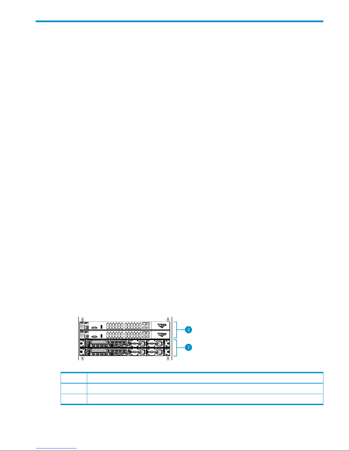
VLS12200 Gateway Components
A VLS12200 Gateway consists of at least two nodes (one primary node and between one and
seven secondary nodes) and dual LAN switches for internal inter-node connections. See the drawing
of racked nodes below. Each VLS12200 gateway node contains hardware data compression,
dual processors, one 4 Gb four-port Fibre Channel HBA, 48 GB of RAM, and two 500 GB SAS
hard drives.
No external storage is included with the VLS12200; instead, the gateway uses external storage
in existing arrays.
Figure 1 Racked Gateway Components
DescriptionItem
Nodes1
Ethernet Switches2
VLS12200 Gateway Components 11
Page 12

Up to six nodes can be added to a gateway for a total of eight nodes in a single gateway. You
can increase capacity by purchasing capacity licenses, each of which adds licensing for one
additional external array LUN and increases maximum external capacity by up to 2 TB.
Adding nodes and licenses increases the gateway storage capacity as shown in Table 1 (page
12). Adding nodes also increases the performance. See the HP StorageWorks VLS12200 Virtual
Library System Quickspec on the HP web site (http://h18006.www1.hp.com/storage/disk_storage/
disk_to_disk/vls/vls_gateway/index.html) for performance data.
Table 1 VLS12200 Gateway Capacity
Maximum capacity without expansion LTUsNodes
50 TB2
70 TB3
90 TB4
110 TB5
130 TB6
150 TB7
170 TB8
12 Introduction
Page 13

2 Hardware Installation
This section details the steps to install the VLS hardware from installation preparation to final cabling.
Preparing for the Installation
Prepare the EVA for the VLS12000 Gateway
Arrays that will be connected to the VLS Gateway must already be setup with the appropriate
configuration as described in the solutions guide, including:
• Command View EVA is installed, at firmware revision 5100 or later, and functioning properly.
• There are either two external Fibre Channel switches/fabrics or two zones on an external
Fibre Channel switch/fabric so that there are two (high availability) data pathways from the
VLS Gateway to the EVA.
• All of the VRaid LUNs required for the VLS have been created on the EVA according to the
design guidelines (for example, each LUN is roughly the same size—2 TB is preferred. The
LUNs can not be read-only. RAID 5 is recommended. Path failover is balanced across both
EVA controllers).
NOTE: Minimum capacity for EVA LUNs is 100 GB. Ensure all EVA LUNs attached to the
Gateway meet this requirement.
If this has not been done, refer to the solutions guide for instructions.
Tools for Installation
• Two people
• #1 and #2 Phillips screwdriver
• Box cutting knife
CAUTION: Do not use any power tools. They could strip or damage connections.
Taking ESD Precautions
To prevent damaging the system, be aware of the precautions you need to follow when setting up
the system or handling parts. A discharge of static electricity from a finger or other conductor may
damage system boards or other static-sensitive devices. This type of damage may reduce the life
expectancy of the device.
To prevent electrostatic damage:
• Avoid hand contact by transporting and storing products in static-safe containers.
• Keep electrostatic-sensitive parts in their containers until they arrive at static-free workstations.
• Place parts on a grounded surface before removing them from their containers.
• Avoid touching pins, leads, or circuitry.
• Always be properly grounded when touching a static-sensitive component or assembly.
Preparing for the Installation 13
Page 14

Grounding Methods to Prevent Electrostatic Discharge
Several methods are used for grounding. Use one or more of the following methods when handling
or installing electrostatic-sensitive parts:
• Use a wrist strap connected by a ground cord to a grounded workstation or computer chassis.
Wrist straps are flexible straps with a minimum of 1 megaohm ±10 percent resistance in the
ground cords. To provide proper ground, wear the strap snug against the skin.
• Use heel straps, toe straps, or boot straps at standing workstations.
Wear the straps on both feet when standing on conductive floors or dissipating floor mats.
• Use conductive field service tools.
• Use a portable field service kit with a folding static-dissipating work mat.
If you do not have any of the suggested equipment for proper grounding, have an authorized
reseller install the part.
For more information on static electricity or assistance with product installation, contact your
authorized reseller.
Unpacking
Place the shipping carton as close to the installation site as possible. Before unpacking the VLS,
inspect the shipping carton for damage that may have occurred during shipment. If you detect any
damage, notify the carrier and HP before unpacking the unit.
Removing the Packing Materials
To unpack the VLS:
1. Open the top of the shipping cartons.
2. Carefully lift the units out of the boxes and remove the packing materials.
3. Place the units on a stable work surface.
NOTE: Inspect the units for any damage that may have occurred during shipment. If damage
is detected, contact your authorized service representative.
4. Remove the accessory kits and documentation from the shipping cartons. Set them aside for
later use.
5. Place shipping materials back into the shipping cartons.
6. Set the shipping cartons aside for later use.
Rack Planning Resources
The rack resource kit ships with all HP or Compaq branded 9000, 10000, and H9 series racks.
A summary of the content of each resource follows:
• Custom Builder is a web-based service for configuring one or many racks. Rack configurations
can be created using:
◦ A simple, guided interface
◦ Build-it-yourself model
• The Installing Rack Products video provides a visual overview of operations required for
configuring a rack with rack-mountable components. It also provides the following important
configuration steps:
◦ Planning the site
◦ Installing rack servers and rack options
14 Hardware Installation
Page 15

◦ Cabling servers in a rack
◦ Coupling multiple racks
• The Rack Products Documentation CD enables you to view, search, and print documentation
for HP and Compaq branded racks and rack options. It also helps you set up and optimize
a rack in a manner that best fits your environment.
Rack Requirements
HP supports the HP System E racks and the HP 10000 Series racks for use with VLS systems. Other
racks might also be suitable, but have not been tested with the VLS.
Rack Warnings
WARNING! To reduce the risk of personal injury or damage to the equipment, before installing
equipment be sure that:
• The leveling jacks are extended to the floor.
• The full weight of the rack rests on the leveling jacks.
• The stabilizing feet are attached to the rack if it is a single-rack installation.
• The racks are coupled together in multiple-rack installations.
• Only one component is extended at a time. A rack may become unstable if more than one
component is extended for any reason.
WARNING! To reduce the risk of personal injury or equipment damage when unloading a rack:
• At least two people are needed to safely unload a rack from a pallet. An empty 42U rack
can weigh as much as 115 kg (253 lb), can stand more than 2.1 m (7 ft) tall, and may become
unstable when being moved on its casters.
• Never stand in front of a rack when it is rolling down the ramp from the pallet. Always handle
a rack from both sides.
Identifying the VLS Shipping Carton Contents
Unpack the VLS shipping cartons and locate the materials and documentation necessary for installing
the VLS. All the rack mounting hardware and documentation necessary for installing a VLS node
into a rack is included in the node shipping carton. All the rack mounting hardware and
documentation necessary for installing a VLS disk array into a rack is included in the disk array
shipping carton.
Rack Requirements 15
Page 16
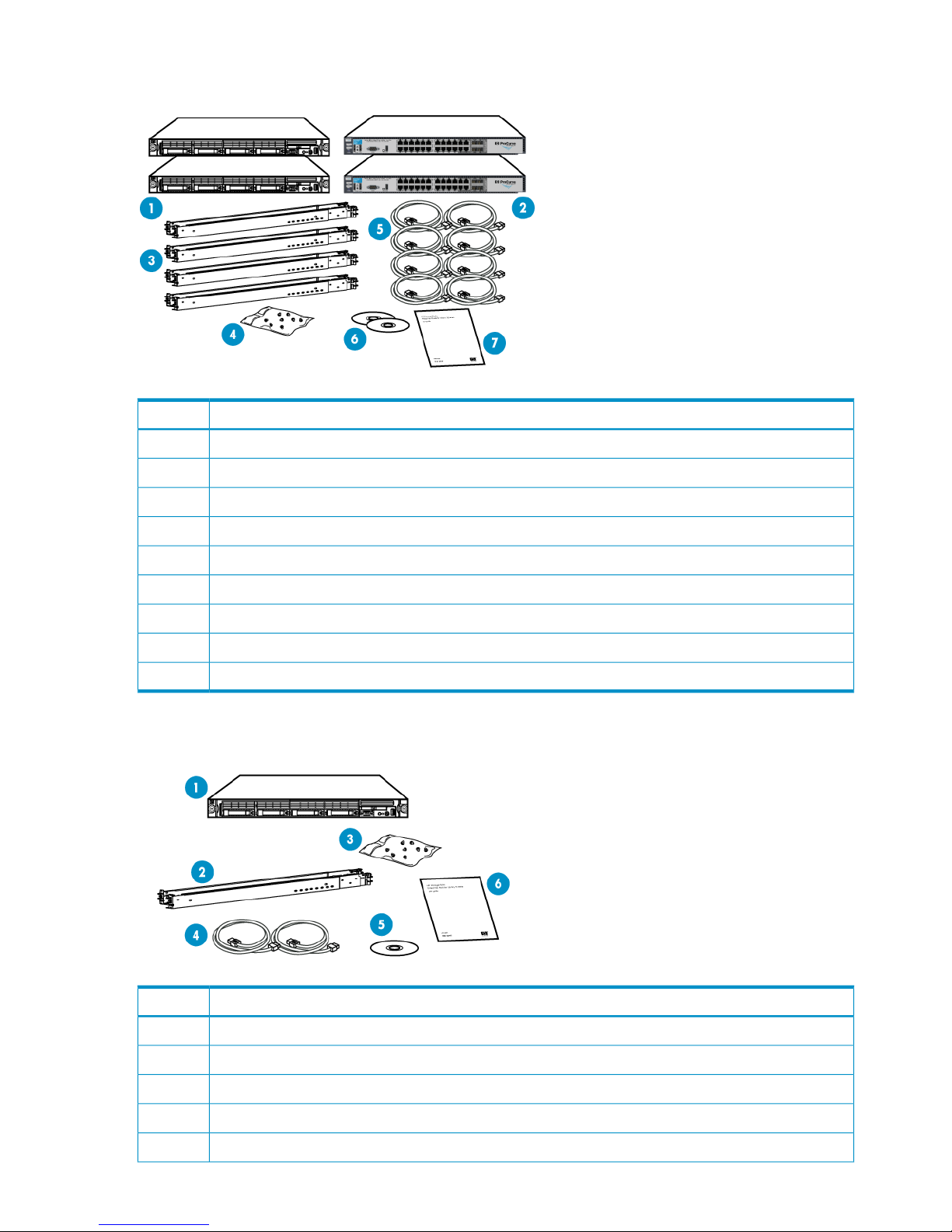
VLS12200 Base System Shipping Carton
DescriptionItem
VLS12200 nodes (2)1
Ethernet switches 6600–24G (2)2
1U rack mounting hardware kits (4) and documentation3
Loopback plugs for FC ports (4)4
Power cords (8)5
VLS Quick Restore DVDs (2)6
Printed VLS node installation poster (1)7
Air plenums for Ethernet switches (2), not shown
Ethernet cables (5), not shown (shipped separately)
VLS12200 Expansion Kit Shipping Carton
DescriptionItem
VLS12200 node (1)1
1U rack mounting hardware kit (1) and documentation2
Loopback plugs for FC ports (2)3
Power cords (2)4
Quick Restore CD (1)5
16 Hardware Installation
Page 17
DescriptionItem
Printed VLS node installation poster (1)6
Ethernet cables (2), not shown (shipped separately)
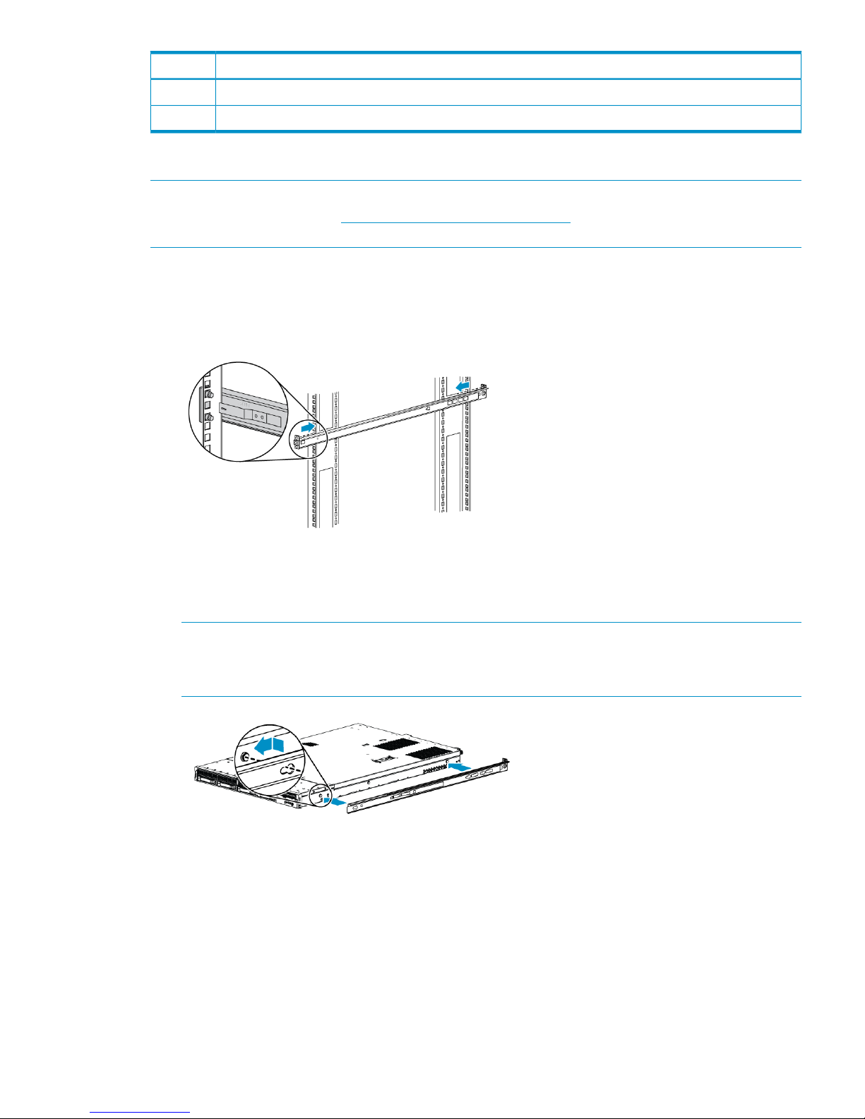
Installing the VLS Node into a Rack
NOTE: If you are installing the node into a telco rack, order the appropriate option kit at the
RackSolutions.com web site: http://www.racksolutions.com/hp. Follow the instructions on the web
site to install the rack brackets.
1. Locate the rail kit — part number 360332–003.
2. Install the two outer slide rails to the rack. The outer rails are marked “FRONT” and “REAR.”
On both sides of the rack, align the rail holes with the holes in the rack and secure with
thumbscrews.
3. Attach the inner rails to the sides of the node.
Align the holes in the rail with the round tabs on the side of the node and secure with
thumbscrews.
NOTE: The inner rails are identical.
The word “FRONT” should face away from the node, but will appear upside-down on one
side.
4. Align the rails on the node with the rails in the rack, and slide the node fully into the rack.
5. Tighten the thumbscrews.
Installing the VLS Node into a Rack 17
Page 18
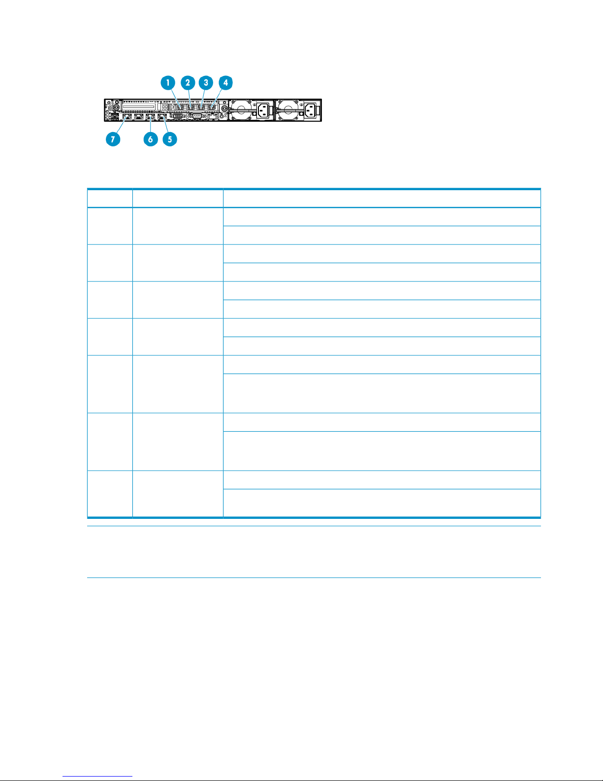
Cabling the VLS Node
Table 2 Cabling the Node
Connects toDescriptionItem
Primary node: connects to your system's backend storage via FC cable.FC port 41
Secondary nodes: connects to your system's backend storage via FC cable.
Primary node: connects to your system's backend storage via FC cable.FC port 32
Secondary nodes: connects to your system's backend storage via FC cable.
Primary node: connects to your system's backup SAN via FC cable.FC port 23
Secondary nodes: connects to your system's backup SAN via FC cable.
Primary node: connects to your system's backup SAN via FC cable.FC port 14
Secondary nodes: connects to your system's backup SAN via FC cable.
Primary node: connects to port 1 of Ethernet switch #2 (SW2) via Ethernet cable.NIC 45
Secondary nodes: connects to the next available port on Ethernet switch #2 (SW2)
via Ethernet cable. Cable secondary nodes to the switch ports 2 through 8 in
sequential order.
Primary node: connects to port 1 of Ethernet switch #1 (SW1) via Ethernet cable.NIC 36
Secondary nodes: connects to the next available port on Ethernet switch #1 (SW1)
via Ethernet cable. Cable secondary nodes to the switch ports 2 through 8 in
sequential order.
Primary node: connects to your system's external network via Ethernet cable.NIC 17
Secondary nodes: connects to your system's external network when using replication
via Ethernet cable.
NOTE: Not all systems use all of the components listed in Table 2 (page 18).
The primary node, node 0, is on the bottom of the stack of nodes. From the bottom to the top they
are: node 0, node 1, node 2, node 3. (The number of nodes will vary from system to system.)
1. Cable the primary node (node 0) and secondary node (node 1) using Table 2 (page 18).
2. If you are installing more than two nodes, cable the nodes using Table 2 (page 18). Start at
node 2 and work your way up the rack.
3. Using Velcro®, secure the cables to the left side of the rack.
4. Install loopback plugs on the nodes in all unused Fibre Channel ports.
18 Hardware Installation
Page 19

IMPORTANT: Do not touch the Fibre Channel cable tips.
Do not secure Fibre Channel cable with cable ties.
Installing the Ethernet Switches into a Rack
Installing the switch into the rack involves installing the rails in the rack, attaching the mounting
brackets to the switch, and installing the switch into the rack. Install the switches immediately above
the Fibre Channel switches previously installed.
1. Locate the following items and set them aside on a stable work surface:
• Two Ethernet switches and two AC power cords
• 1U rails, mounting brackets, and hardware to secure the rails to the rack
• Screws to secure mounting brackets to the switch
2. Align the mounting holes at each end of a rail with the holes on the front and back rack posts
so that they are at the same height.
3. For a square-hole rack, leave the pre-installed square-hole pin in each rail. Unscrew and
re-install the 10-32 screw on each rail to secure it to the rack.
For a round-hole rack, install the alternate round-hole pins that are shipped with the kit to set
the rails in the rack. Install the alternate roundhole screws to secure the rails. (The round-hole
screws have a different shoulder than the square-hole screws.)
4. Place a mounting bracket against one side of the switch. The bracket should be flush with the
front (port side) of the switch.
5. Secure the bracket to the switch with four M4 8mm screws.
6. Perform these steps again to install the other mounting bracket on the other side of the switch.
7. Slide the switch onto the rails until the switch is fully inserted and the mounting hole in each
bracket lines up with the mounting holes in the rack.
8. Connect each power cord to a power supply and secure the cord with a Velcro® strap. Route
each cord through the rack.
Installing the Ethernet Switches into a Rack 19
Page 20
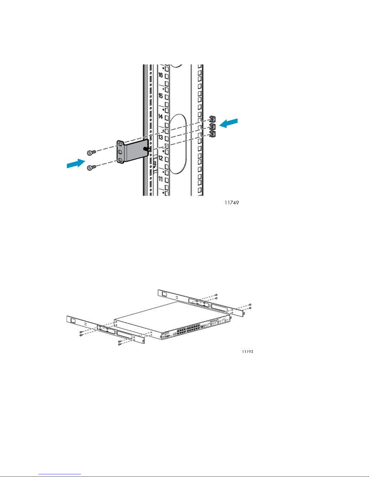
Installing Cage Nuts and Rail Flanges
1. On the rack vertical posts, mark the holes (three on each front vertical post and two on each
rear vertical post) that will be used by the rail flanges. Then, from the inside of each vertical
post, insert a cage-nut into each marked hole.
2. From the front of the rack, secure the mounting flanges to the marked holes, using screws
shipped with the rails.
3. Attach a washer and nut to the posts at the end of each mounting flange. Leave them loose
and towards the open edge of the post.
Attaching Rails to the Ethernet Switch 6600-24G
1. Align the rail with the switch. The two holes at the front of the rail must align with the two
holes at the front of the switch. The bracket end of the rail is towards the front of the switch.
2. Insert two of the pan-head screws through the rail and into the switch at the front of the switch.
Tighten the screws.
3. Insert two of the pan-head screws through the appropriate holes in the rail and into the switch
at the back of the switch. Tighten the screws.
4. Perform these steps again to install the other rail on the other side of the switch.
20 Hardware Installation
Page 21
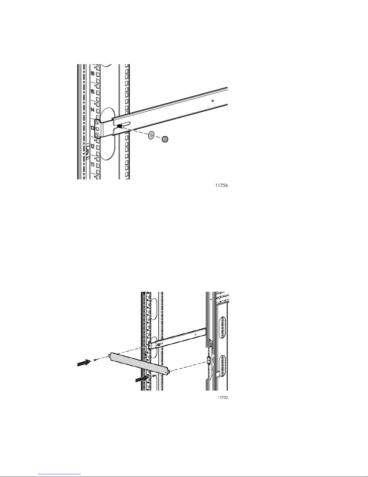
Mounting Ethernet Switch 6600-24G into the Rack
1. From the back of the rack, align the grooved ends of the switch rails with the posts on the
mounting flanges. Placing the grooved ends between the mounting flange and the loose washer
and nut provides guidance.
2. Slide the switch fully into the rack.
3. Tighten the washer and nut on both sides of the rack to secure the switch rails to the mounting
flanges.
4. From the back of the rack, on each side of the switch, insert an M5 screw through the holes
in the rail and into the holes in the rack.
5. Tighten the M5 screws to secure the switch to the rack.
6. Attach a power cable to the switch's power supply.
7. Plug the power cable into an AC power source.
8. Route the power cable through the left side of the rack and plug it into a PDM.
9. Attach a 1U cover plate to the front of the rack.
Installing the Ethernet Switches into a Rack 21
Page 22
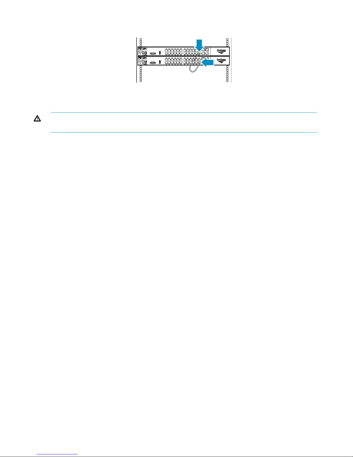
Cabling Ethernet Switches 6600–24G
1. Connect an Ethernet cable from port 24 on switch #1 to port 24 of switch #2.
2. Using Velcro®, secure the excess cable to the right side of the rack.
WARNING! Do not connect cables to unused ports on Ethernet switch #1 or #2. Doing so could
result in data loss.
22 Hardware Installation
Page 23

3 Multi-node Setup
This section explains how to configure the identities of each node after the nodes and other
components of the system are installed and cabled.
Configuring Primary Node 0
To configure the primary node:
1. On the primary node, connect to the serial port or use the keyboard and mouse ports to
connect to a console.
2. Power on the primary node. The node will now run cable checks and configuration checks.
After several minutes, a menu will appear on your monitor asking whether the node is a
primary (master, m) or secondary (slave, s) node.
3. Enter m. The node will then run cable checks and configuration checks.
4. After the checks are complete the node will reboot automatically. Wait for the primary node
to fully boot.
Rebooting is complete when you receive the “Initializing node#” and then “Initializing for
node# completed.” messages in the systems notifications (if you have DHCP enabled) of
Command View VLS or when you see the login prompt on the terminal.
5. Set the IP address and other public network configurations on the VLS. Refer to Setting the
Network Settings for instructions.
Configuring the Secondary Nodes 1 through 3
To configure the secondary nodes (nodes 1 through 3):
1. On the secondary node, connect to the serial port or use the keyboard and mouse ports to
connect to a console.
2. Power on the primary node and all previously installed secondary nodes of the VLS.
3. Power on the secondary node being added to the VLS.
The node will then run cable checks and configuration checks, and display the world wide
part number (WWPN).
After several minutes, a menu will appear on your monitor asking whether the node is a
primary (master, m) or secondary (slave, s) node.
NOTE: If you are performing a "hot add" of a secondary node, you can present the LUNs
at this time. See “Presenting the LUNs” (page 24).
4. Enter s.
5. At the prompt, enter the node number (next sequential node number), and the node will then
automatically reboot.
NOTE: Node numbering must be sequential with no gaps. Gaps in ID numbering will prevent
the VLS from recognizing any nodes with an ID after the gap. For example, if node numbering
is 0, 1, 2, 4, the VLS will not recognize node 4.
6. Once the new secondary node has finished rebooting, log on to Command View VLS and
log in as the administrator. See “Opening a Command View VLS Session from a Web
Browser” (page 79).
7. Select the System tab.
8. Select Nodes from the navigation pane.
9. Repeat these steps to add nodes until all of the nodes are listed in the navigation pane.
Configuring Primary Node 0 23
Page 24

4 Storage Configuration
This section describes how to configure the storage after the nodes have been configured.
Establishing Communication Between the VLS12200 Gateway and the
EVA
This section describes how to establish communication between the VLS12200 Gateway and the
EVA by adding hosts and ports to the EVA and then presenting the LUNs.
Verifying Array Zoning
Verify that you have configured the zoning between the EVA ports and all storage ports on all the
nodes of your VLS Gateway. For example, storage ports 2 and 3 on each node should connect
to different SAN zones/fabrics; EVA controllers should also be connected to both zones/fabrics.
If you have not done so, refer to the HP StorageWorks VLS and D2D Solutions Guide to do so
now.
Presenting the LUNs
NOTE: If you have noted the list of WWPNs while performing the multi-node setup (see
“Configuring the Secondary Nodes 1 through 3” (page 23)), go directly to step 2 of the procedure
below.
1. Gather the device WWPNs.
a. From Command View VLS, select the System tab.
b. From the Navigation Tree, select Nodes, then a specific node, then Fibre Channel.
The status pane displays information about the Fibre Channel ports including the world
wide port names (WWPNs) (Figure 2 (page 24)).
Figure 2 Fibre Channel details window
c. Write down the WWPN for each storage port on the node. There is no need to write
down the WWPNs for the host ports.
d. Repeat these steps for each node on the VLS Gateway.
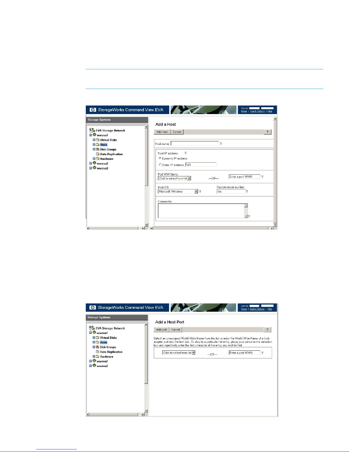
2. Create a host entry for the VLS device using the WWPNs gathered in the previous step:
a. Access Command View EVA.
24 Storage Configuration
Page 25
b. From the Storage tab navigation tree, select the EVA storage system that will be used for
the VLS Gateway, then Hosts.
c. In the status pane, click Add Host to display the Add a Host screen.
d. Enter the Host name (preferably the VLS hostname), enter or select one of the WWPNs
(noted in the previous step) in the Port WW Name box on the VLS Gateway, and select
Linux for the Host OS (Figure 3 (page 25)).
NOTE: If a WWPN is not in the Port WW Name box, there may be a zoning error.
After creating the host entries, verify that your zoning is correctly configured.
Figure 3 Add a Host window
e. Click on Add Host.
f. From the Storage tab navigation tree, select the host you just added.
g. Click on the Ports tab in the status pane.
h. Click on Add port, select one of the VLS Gateway WWPNs (noted in the previous step)
from the pull-down list or type one of the appropriate WWPNs, then click Add port
(Figure 4 (page 25)).
Figure 4 Add a Host Port window
Establishing Communication Between the VLS12200 Gateway and the EVA 25
Page 26
i. Continue to add ports until all of the ports on the VLS Gateway are added and are listed
on the Host Properties screen in the status pane.
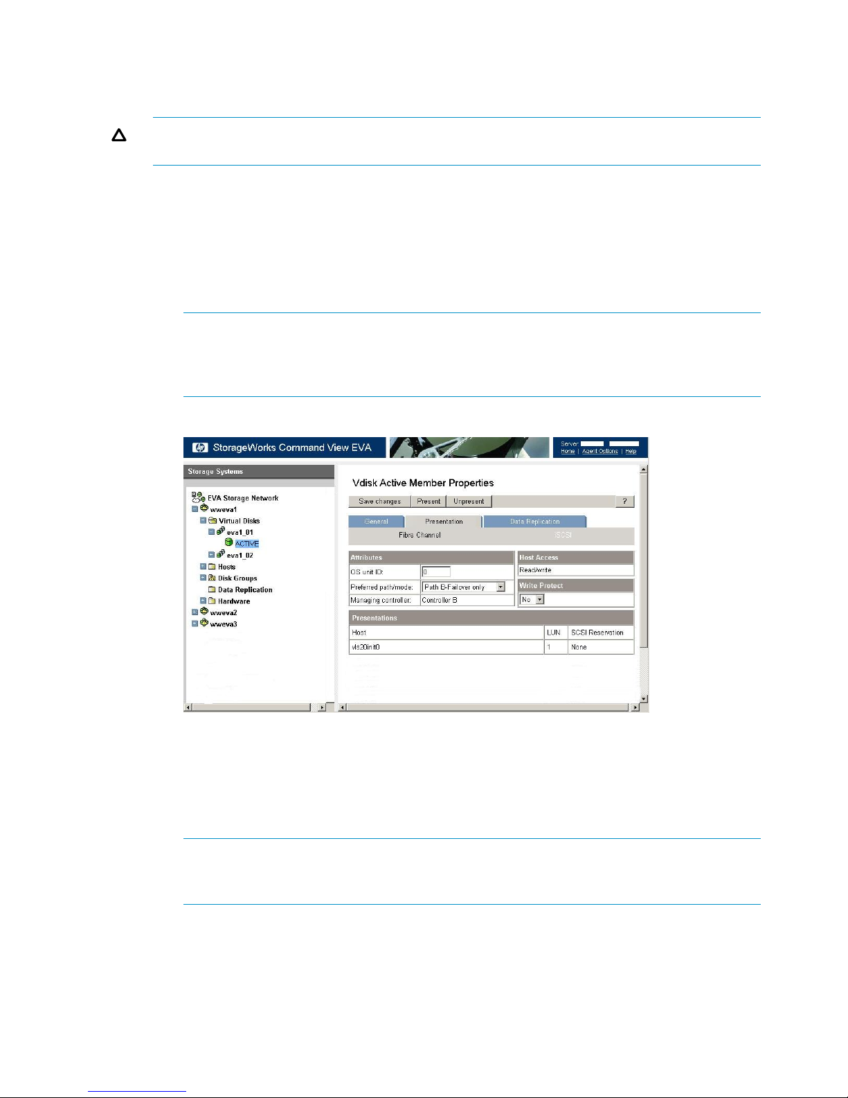
3. Present the LUNs:
CAUTION: Present only the disks that you wish to use with the VLS Gateway because existing
data will be destroyed during storage pool configuration.
a. In Command View EVA, in the Storage tab navigation tree, select the EVA for the VLS
Gateway storage system, Virtual Disks, the disk name that you want to present, then
ACTIVE under that disk.
b. Select the Presentation tab.
c. Ensure that Write Protect is set to No.
d. Ensure that the Preferred path/mode is set to either Path A-Failover only or Path B-Failover
only (Figure 5 (page 26)).
NOTE: Set the Preferred path/mode for half of the disks to Path A-Failover only, and
to Path B-Failover only for the other half of the disks. This balances the data traffic across
both A and B controllers. For more information on data traffic balancing, see “Array Dual
Pathing” (page 103).
Figure 5 Vdisk Active Member Properties window
e. Click on Present, then select the VLS Gateway host (just created) on the Present Vdisk
screen on the status pane.
f. Click on Present Vdisk.
g. The Operation Succeeded message displays on the status pane. Click OK.
h. Repeat these steps for each disk to present to the VLS.
NOTE: If needed, these disks can be unpresented. See Deleting Array LUNs. If you
unpresent a LUN, you must then reconfigure the LUN numbering for all LUNs on the VLS
Gateway that follow the unpresented LUN in sequential numbering.
Managing VLS12200 Gateway Capacity
There are several ways to manage the capacity of your Gateway system:
• Add external LUNs to the VLS Gateway configuration. See Discovering Array LUNs.
• Delete external LUNs from the VLS Gateway configuration. See Deleting Array LUNs.
26 Storage Configuration
Page 27
• Create storage pools. See Configuring Storage Pools.
• Destroy storage pools. See Deleting Array LUNs
• Enable device-side data compression when creating new tape drives. See “Creating Tape
Drives” (page 97)
Discovering Array LUNs
1. Discover the LUNs, either by rebooting the entire VLS Gateway or:
a. Open a Command View VLS session and log in as the administrator. See “Opening a
Command View VLS Session from a Web Browser” (page 79).
b. In the Storage tab navigation tree, select Storage LUNs.
c. Select Discover Unconfigured Storage from the task bar. This causes the VLS to recognize
all presented LUNs and return the following message: # storage lun(s)
discovered. # storage lun(s) deleted. At this point, the LUNs are still
unconfigured.
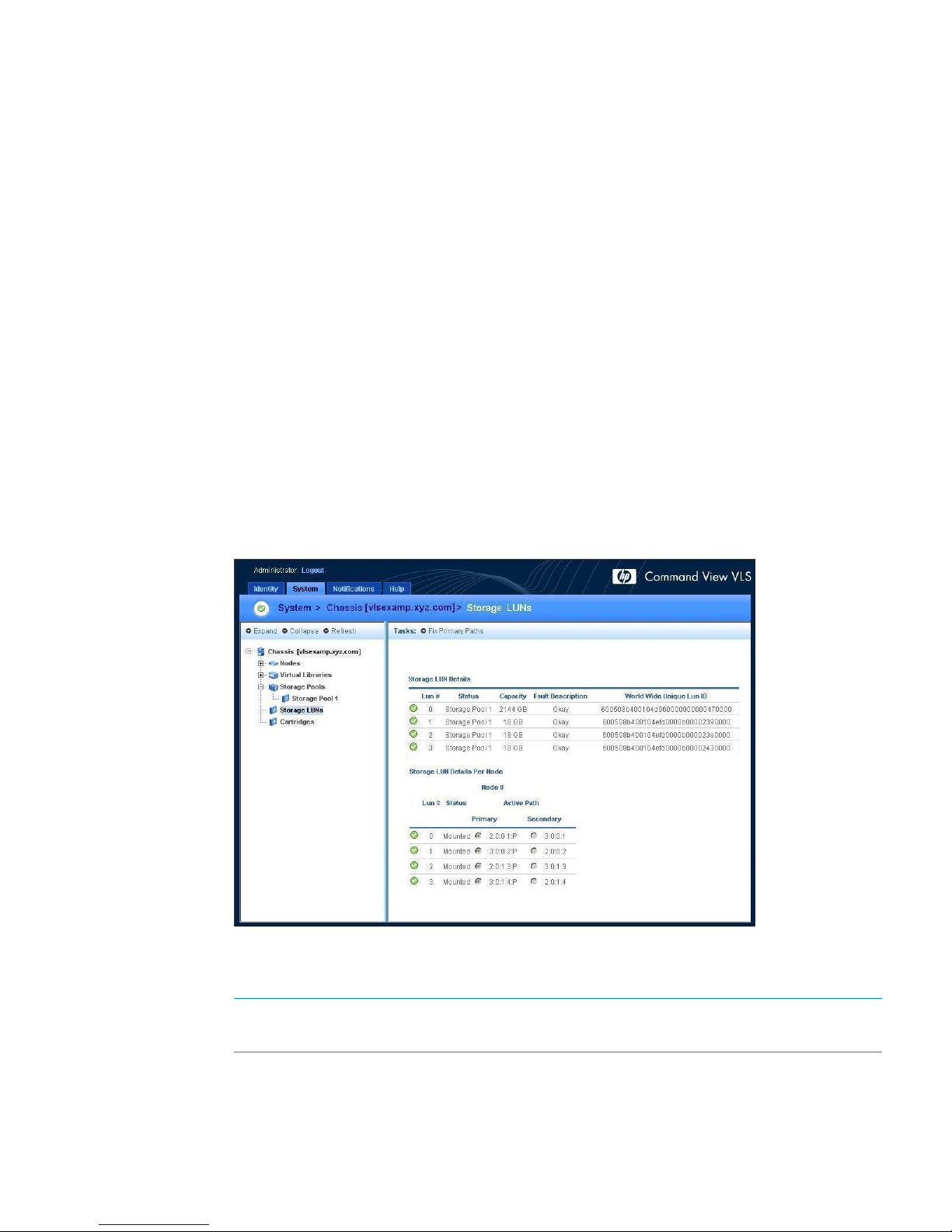
2. Verify that the LUNs are properly assigned and that there are two data paths for each LUN.
a. Open a Command View VLS session and log in as the administrator. See “Opening a
Command View VLS Session from a Web Browser” (page 79).
b. In the Storage tab navigation tree, select Storage LUNs.
c. Under All, select All Nodes in the Nodes dialog box, then click View to display Storage
LUN Details and Storage LUN Details Per Node (Figure 6 (page 27)).
Figure 6 Storage LUNs details window
d. Ensure that all LUNs are listed under each node, and that each has a preferred and
secondary path.
NOTE: If a LUN is not recognized by each node, the LUN is unusable. Present the LUN
to any node that does not yet recognize the LUN.
3. Resolve any errors, if necessary.
If there is a license violation, you can still view all the LUNs. Either install more licenses or
remove the LUNs that do not belong. This will eliminate the violation. See Deleting Array
LUNs.
Managing VLS12200 Gateway Capacity 27
Page 28
Deleting Array LUNs
CAUTION: Deleting an EVA LUN that is part of an existing storage pool will result in the loss of
all cartridge data for that storage pool.
To remove a LUN from the device:
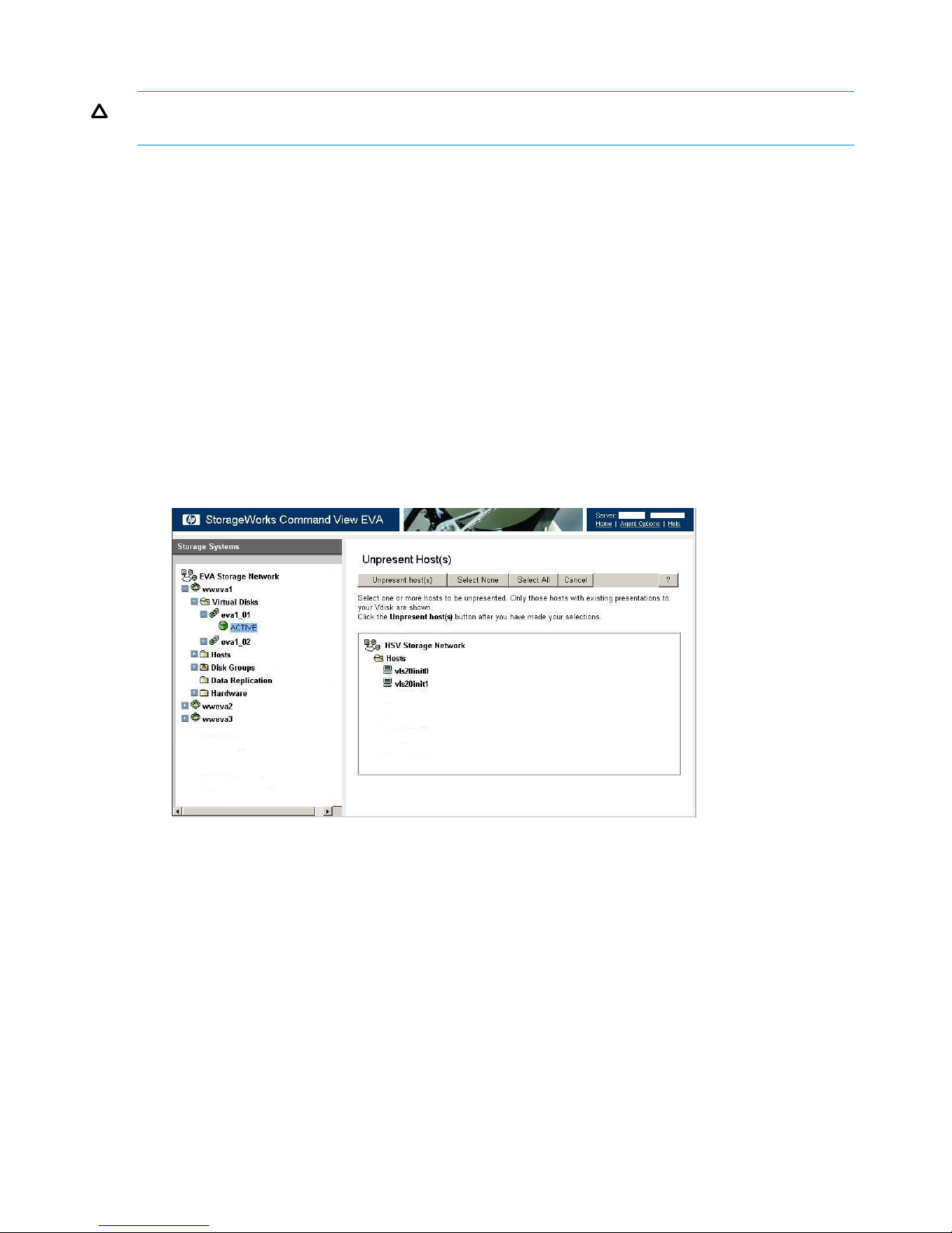
1. Unpresent the LUN to the VLS (see instructions below) or delete the LUN from the external
array.
2. Restart emulations or reboot the device (see “Restarting VLS Device Emulations” (page 109) or
“Rebooting the System” (page 75)).
3. Discover unconfigured storage (see Discovering Array LUNs). This deletes the removed LUNs
from the configuration.
To unpresent a LUN:
1. In Command View EVA, Storage tab navigation tree, select the EVA for the VLS Gateway
storage system, Virtual Disks, the disk name that you want to present, then ACTIVE under that
disk.
2. Select the Presentation tab for the ACTIVE Vdisk.
3. Click on the Unpresent button.
4. Select the disk to remove from the host (Figure 7 (page 28)).
Figure 7 Unpresent Host(s) window
5. Click on Unpresent host(s).
6. Click OK from the confirmation dialog box.
7. Click OK under Operation Succeeded in the status pane.
8. If there is a break in numbering of the remaining LUNs, LUN numbers after the break must be
reconfigured. See “Multi-node Setup” (page 23) for detailed instructions.
28 Storage Configuration
Page 29
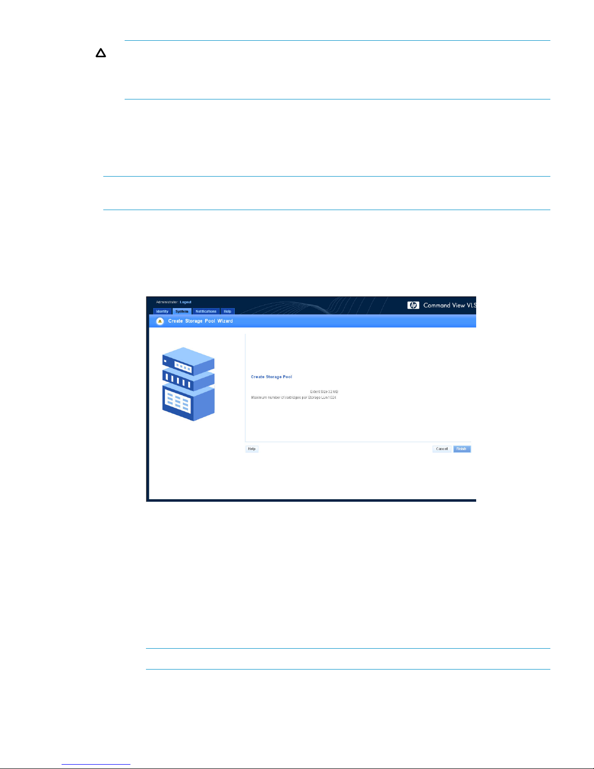
CAUTION: LUN numbering must be sequential with no gaps. Gaps in LUN numbering will
prevent the VLS Gateway from recognizing any nodes with any LUNs after the gap. For
example, if LUN numbering is 0, 1, 2, 4, 5, the VLS Gateway will not recognize LUNs 4 and
5.
Configuring Storage Pools
VLS automatically creates one storage pool. HP recommends that a single storage pool is used
even for multiple arrays. However, if additional pools are needed, you must create them. To do
so:
NOTE: The VLS Gateway can have either one storage pool for all LUNs, or one storage pool
for each array. Refer to the solutions guide for details.
1. Create a storage pool(s):
a. Open a Command View VLS session and log in as the administrator. See “Opening a
Command View VLS Session from a Web Browser” (page 79).
b. In the Storage tab navigation tree, select Storage Pools.
c. From the task bar, select Create Storage Pool. The Create Storage Pool Wizard is displayed.
d. Click Finish. CREATE STORAGE POOL COMPLETED is displayed.
e. Click Return.
f. If you are creating a separate storage pool for each array, repeat this process for each
storage pool.
2. Add the array LUNs to the storage pool(s).
a. Open a Command View VLS session and log in as the administrator. See “Opening a
Command View VLS Session from a Web Browser” (page 79).
b. In the Storage tab navigation tree, under Storage Pools, select a storage pool.
c. From the task bar, select Add External LUN. The Add External LUN Wizard is displayed.
NOTE: This task does not appear if there are no licenses available.
d. From the list of available unconfigured LUNs, select the LUNs to add to the pool. (By
default, all LUNs are selected.)
Managing VLS12200 Gateway Capacity 29
Page 30

NOTE: View the World Wide Unique Lun ID on the storage LUN list (on the System
screen) to identify which LUNs are associated with each array.
e. Use the Format check box to indicate whether the selected LUNs are initialized (formatted)
when added to the pool.
NOTE: Do not format the LUNs when manually creating previously existing pools after
performing a disaster recovery of the primary node. If you do not format the LUN, all
cartridge data in that pool is retained.
f. Click Finish to add the LUNs to the pool.
3. If you started with an unconfigured device (i.e., no LUNS added to any storage pools) before
you added LUNs to the storage pools, you need to reboot the device to enable the new storage
pools.
The pool is now ready to have cartridges created.
NOTE: If you created storage pools on a LUN that already contained cartridges, update the
Allocated Capacity numbers. To do this, select Cartridges from the system navigation tree, then
select View for the All listing.
Destroying Storage Pools
Command View VLS allows you to destroy a specific storage pool or all storage pools.
Systems with deduplication enabled must enter Maintenance Mode (using Restart Emulations in
Maintenance Mode from the task bar) before destroying any storage pools. Maintenance Mode
reboots the system with deduplication disabled and the front fibre ports down. After destroying
the storage pools, you need to reboot the device again to return to normal operation.
NOTE: If there are cartridges in the pool or pools when they are destroyed, emulations will
restart. To avoid this restart, delete all cartridges from the pool prior to deleting the pool. (see
“Destroying Cartridges” (page 107)).
To delete a single storage pool:
1. Open a Command View VLS session and log in as the administrator. See “Opening a
Command View VLS Session from a Web Browser” (page 79).
2. In the Storage tab navigation tree, select the pool to delete (listed under Storage Pools).
3. From the task bar, select Destroy Storage Pool. The Confirm Destroy <storagepool name>
window is displayed (Figure 8 (page 31)).
30 Storage Configuration
Page 31

Figure 8 Confirm Destroy Storage Pool window
4. Select Next to destroy the pool.
A second page of the Confirm Destroy <storagepool name> screen is displayed, containing
the following text: WARNING: Existing data in StoragePool # will be destroyed and cannot
be recovered. This step cannot be reversed.
5. Select Finish to display the screen confirming that the storage pool has been destroyed.
6. Select Finish again to return to the system screen.
You can now either use the LUNs previously assigned to the destroyed pool in other pools,
or they can be deleted.
To delete all storage pools:
1. Open a Command View VLS session and log in as the administrator. See “Opening a
Command View VLS Session from a Web Browser” (page 79).
2. In the Storage tab navigation tree, select Storage Pools.
3. If you wish to destroy all storage pools, from the task bar, select Destroy All Storage Pools.
The Confirm Destroy All Storage Pools screen is displayed.
4. Select Next to destroy the pools.
Either recreate storage pools using the LUNs previously assigned to the destroyed pool(s), or
delete them.
Installing Additional Licenses
Your VLS system may require any of the following licenses:
• Capacity:
A VLS capacity license must be installed on the VLS when you add additional EVA array LUNs
beyond the ten base licenses included with each node.
If you are in a license violation state, all VLS read/write operations are disabled until either
sufficient licenses are installed to support the storage, or the excess storage is removed. When
you have cleared a license violation by installing an upgrade capacity license, the VLS
read/write operations are automatically enabled without requiring a reboot.
Installing Additional Licenses 31
Page 32

Unconfigured VLS12200 Gateway array LUNs are counted by the system; therefore, they can
contribute to license violations.
• Deduplication:
A VLS deduplication license must be installed on the VLS before you can use the deduplication
feature. The number of deduplication licenses must match or exceed the number of capacity
licenses installed. After you install the deduplication licenses, the VLS system automatically
enables the deduplication feature for all supported backup types.
• Replication:
A VLS replication license must be installed on the VLS before you can use deduplication-enabled
replication. Without the license, you may replicate backups across the LAN/WAN. However,
you need the replication license to replicate backups that have been deduplicated.
Deduplication-enabled replication requires one license per node on the target site.
• Secure Erasure:
When you delete a cartridge, this feature overwrites deleted cartridge data with a specific
data pattern so the data cannot be recovered. This is comparable to tape shredding of physical
tapes.
Follow these steps to install capacity, deduplication, replication, and Secure Erasure licenses:
1. Use Command View VLS to obtain the VLS system serial number from the Identity tab.
2. Locate the paper or email entitlement certificate for the licenses you purchased. (You selected
the delivery method during the ordering process.)
HP recommends purchasing electronic certificates over physical certificates for faster delivery
and the convenience of not having to manage (either file away or throw away) confidential
paper certificates.
3. Log on to http://www.webware.hp.com.
4. Select Generate Licenses.
5. Sign in. If you are a new user, follow the onscreen instructions.
6. Enter the order number from the entitlement certificate.
7. Enter the VLS serial number. You will receive a license key immediately onscreen and via
email.
8. Copy the license key.
9. In Command View VLS, select the System tab.
10. Select Chassis on the navigation tree.
11. Select Licensing from the task bar.
The Manage Upgrade Licenses screen displays all of the existing licenses.
12. Select Add License.
13. In the empty field that displays, paste the license key.
14. Select OK.
The screen returns to the Manage Upgrade Licenses list and includes the newly installed licenses.
NOTE: When installing deduplication or Secure Erasure licenses, the VLS system will automatically
reboot. This may take a few minutes to begin; when it does, you will see a message on the
Notifications tab.
32 Storage Configuration
Page 33

5 Automigration/Replication
Instead of the preferred method of copying virtual media to physical media via the backup
application, another option is to perform transparent tape migration via the VLS device using
automigration. Automigration describes the feature in which the Virtual Library System acts as a
tape copy engine that transfers data from virtual cartridges on disk to a physical tape library
connected to the VLS device. The VLS automigration feature supports two different schemes:
• Echo copy automatically synchronizes the physical cartridges to matching virtual cartridges
(with the same barcodes) based on user-defined policies, and is totally transparent to the
backup application.
• Using smart copy, the automigration process is under the control of the backup application,
managed via the VLS SMI-S interface. This requires the backup application to support the HP
smart copy interface.
You can also copy virtual media using replication. Replication provides automigration from the
source VLS across the LAN/WAN to a remote virtual destination library. See “Replication
Concepts” (page 35).
This section describes automigration topics from overall automigration concepts to specific operations
you can perform on your system.
NOTE: Throughout the automigration windows, a SAN library refers to a destination library that
is connected to the source library through the SAN and uses the automigration feature. A LAN/WAN
library refers to a remote destination library that is connected to the source through the LAN/WAN
and uses the replication feature.
NOTE: When a list of slots is displayed, the message, “[#] items found, displaying 1 to 20.”
appears. If there are more than 20 items found, scroll through them using the arrows pointing right
and left at the far right-hand side at the top of the list. Also, in some cases, only available slots or
only slots containing tapes appear in the list.
NOTE: For each procedure described in this chapter, at least one means of access to the relevant
screen or menu is specified. However, links are often provided in the main window that can be
used as a shortcut to other windows or menus.
Understanding Automigration Concepts
Before using automigration, review the information in this section. This will allow you to create
copy pools and automigration policies appropriate to meet your storage needs.
Echo Copy Concepts
Echo copy acts as a transparent disk cache to the physical library, so that the backup application
writes to virtual cartridges in the virtual library. Automigration then automatically schedules the
copies from virtual cartridges to physical cartridges with matching barcodes, based on the
automigration policies the user establishes.
Echo copy is managed through the automigration software, not the backup application. For that
reason:
• The destination library is not visible to the backup application, so it does not need licensing.
• Copy traffic is no longer routed through the SAN.
• All destination tapes created by echo copy are in the native tape format, so they can be
restored directly from any tape drive or library that is visible to the backup application.
When determining whether to use echo copy pools, remember:
Understanding Automigration Concepts 33
Page 34

• The backup application will not be aware of any copy failures.
• Any mistakes in destination library media management will also affect the virtual cartridges.
For example, if new tapes are not loaded into the destination library, the physical copy will
not exist.
• The destination library can only be used for copy operations.
• Echo copy is a full tape copy, rather than an incremental change copy, so it can be an
inefficient use of media if you are using non-appending copy pools in your backup jobs.
An echo copy pool is used to define which destination library slots are to be echoed into a specified
virtual library. Automigration then monitors the echo copy pool slots to detect cartridge loads/ejects
in the destination library, and automatically synchronizes the virtual cartridges to the destination
cartridges, creating the matching virtual cartridges as needed.
This means that when new destination tapes are loaded, automigration will automatically scan
them (read the backup application headers) and then automatically create matching virtual cartridges
in the virtual library specified for that echo copy pool.
NOTE: The automatic scanning of new cartridges can take a long time if all the tape drives in
the destination library are busy with higher priority operations such as copies. Therefore, it is best
to load new tapes when copies are not running.
Data written to echoed virtual cartridges will be automatically copied onto matching destination
tapes based on the echo copy policy. An echo copy policy defines for each source virtual library
the copy window (start and end times), the copy on eject option, and the time in days for expiration
after eject. If destination tapes are ejected, the matching virtual tapes are automatically moved to
the firesafe and are deleted at the policy-defined expiration time. This ensures the device does not
fill up its disk space with older cartridges. See “Creating an Echo Copy Pool” (page 40) to create
a policy. If virtual tapes are ejected by a backup application, the matching destination tapes are
also automatically ejected into the destination library mailslot when the copy operation is complete.
When an echo copy is ejected (mailslot eject box is checked), the echo copy is performed, then
the eject is carried out. This results in the echo copy being placed in the device's firesafe and
maintained according to the established policy. If a destination tape was ejected while a copy
was pending, then notifications in the VLS GUI will inform the user that they have interrupted the
copy process.
Smart Copy Concepts
Smart copy allows the backup application to trigger copies from virtual cartridges to destination
cartridges, and the VLS then performs that copy inside the device. The backup application can
only use this feature if it supports the HP smart copy mechanism (via SMI-S v1.3 or later copy
services).
Keep in mind the following when determining whether to use smart copy pools:
• The destination library is not visible to the backup application.
• Copy traffic is no longer routed through the SAN.
• All destination tapes created by smart copy are in the native tape format, so they can be
restored directly from any tape drive or library that is visible to the backup application.
• Because the copy jobs are initiated from the backup application, the backup application will
be aware of any copy failures.
• The destination library can only be used for copy operations.
A smart copy pool is used to define which destination library slots are available as SMI-S copy
targets for a specified source virtual library. Smart copy pools automatically detect all tapes in the
destination library slots that are assigned to that pool. Destination tapes are unrelated to virtual
cartridges – that is, they have different barcodes and headers. Smart copy jobs are initiated by
34 Automigration/Replication
Page 35

the backup application using SMI-S V1.3 software, and the VLS then performs the specified copy
(for example from a virtual cartridge to a destination cartridge, or from a destination cartridge
back to a virtual cartridge, etc.). The backup application tracks the virtual cartridges and the
destination cartridges separately since they have different barcodes and potentially different
contents.
NOTE: When smart copy jobs are triggered, they can override (reschedule) lower priority jobs,
such as echo copy jobs, up to the maximum number of tape drives allocated to their smart copy
pool. If you configure both smart copy pools and echo copy pools on the same VLS, it is advised
that some destination library tape drives remain unallocated to smart copy pools so that echo copy
operations can still continue while smart copy is active.
Replication Concepts
Replication provides automigration via LAN/WAN between two VLS devices. Because replication
is a feature of automigration and uses the same Echo Copy policies that allow flexible cartridge/slot
based configuration, any number of different replication configurations can be supported. You
establish a replication policy and echo copy pools using Command View VLS in the same way
you set up automigration with a destination library on the SAN.
NOTE: The replication feature cannot use smart copy, only echo copy.
During replication, the source VLS copies data to the echo copy pools on a replication library that
is on the source. During the user-defined availability window, this replication library migrates data
to the destination library, known as the LAN/WAN replication target.
The following are two of many possible replication configurations:
• Data center to data center
Designate one VLS as the source and a second VLS as the destination. Configure the destination
VLS to present a LAN/WAN replication target that is visible to the source VLS. The source
VLS performs normal backups during the regular backup window, and during the availability
window the source virtual cartridges automatically migrate to matching virtual cartridges on
the destination VLS. The same configuration is also used in the other direction so there is a
backup library and a LAN/WAN replication target library on both devices.
• Branch office to a main data center
Divide a single destination target into multiple slot ranges to allow a many-to-one configuration
without needing a separate replication library for each branch office. In this way, the VLS
replication can scale to hundreds of branch offices all replicating to a single large device.
Replication can be configured to operate in one of two modes:
• Deduplication-enabled replication — the virtual cartridge on the source VLS is deduplicated
against the virtual cartridge on the target VLS. In this manner, only data that has changed is
transmitted over the network to the target VLS. This mode requires that deduplication is licensed
and enabled on both the source and the target VLS.
• Whole cartridge replication — the entire virtual cartridge is copied from the source VLS to the
target VLS.
Understanding Automigration Concepts 35
Page 36

NOTE: All of the information on automigration also applies to replication except where specifically
dealing with physical tapes (e.g., ejecting media) and where noted. Otherwise, where the
information refers to physical cartridges, for replication assume virtual cartridges instead.
NOTE: Replication is deduplication-enabled if you have purchased the appropriate replication
and deduplication licenses, and your backup ISVs and data types are supported for deduplication.
Check the Accelerated deduplication ISV support matrix at http://www.hp.com/go/ebs/ to see
if your system supports deduplication.
Tape Initialization
When you first configure deduplication-enabled replication on your VLS and set up an echo copy
pool to a LAN/WAN destination, the first round of data migration is not deduplicated because
there is not yet a set of backups on the target VLS to deduplicate against. Because the first full set
of backups can be very large, the VLS system includes a tape initialization process. You can
transport the first full set of backups to the target VLS using physical tapes rather than the network.
This tape initialization process is optional and must be enabled by the administrator when creating
the echo copy pool.
The tape initialization process works, very generally, like this:
1. Set up the LAN/WAN replication target on the remote site
2. Set up an echo copy pool on the source site
3. Run a standard deduplication backup on the source site
4. Export the full backup to physical tapes
5. Transfer the physical tapes to the remote site
6. Import data from the tapes onto the remote LAN/WAN replication target
Once the tape initialization process is complete, the automatic migration of deduplicated data
from the source site to the target site over the LAN/WAN begins. See “Exporting Data to Physical
tapes for Tape Initialization” (page 59) and “Importing Data from Physical Tapes for Tape
Initialization” (page 60) for the specific procedures.
Connecting a Destination Library
Automigration requires one or more dedicated destination libraries to be connected to the VLS
device.
Supported Destination Library Configurations
Automigration is supported on:
• HP MSL series tape libraries
• HP EML series tape libraries or library partitions
• HP ESL E-series tape libraries or library partitions
• HP VLS virtual libraries
36 Automigration/Replication
Page 37

Using automigration, you can share a single destination library across multiple virtual libraries
(maximum of 20 drives on the physical libraries), or configure multiple destination libraries to be
used in a single virtual library.
CAUTION: Automigration only supports destination libraries that have homogeneous drive types;
for example, all drives are LTO-2. A mixture of drive types in the destination library, such as LTO-3
and LTO-2, is not supported.
NOTE: Automigration allows you to use a VLS as a destination library. Because of this feature,
it can also be used as a device-to-device local replication scheme.
Connecting a Destination Library to the VLS12200 Gateway
To connect the destination library to a Gateway device:
1. Connect your destination library to the VLS Gateway by connecting the library into the existing
SAN zone that contains the arrays for this device.
2. Reboot the VLS. Upon reboot, the device detects the newly connected destination library.
Managing and Unmanaging a Destination Library
To manage a library is to enable automigration by connecting the source library to a destination
library that is already on the VLS. Until you manage the destination library, it cannot communicate
with the source. The process for managing destination libraries is different for SAN libraries than
for LAN/WAN libraries. See “Managing a SAN Library” (page 37) or “Managing a LAN/WAN
Replication Library” (page 37).
An unmanaged library is a library that is not recognized by and using automigration or replication.
The process for unmanaging destination libraries is the same for both SAN and LAN/WAN
libraries. See “Unmanaging a SAN or LAN/WAN Library” (page 38).
Managing a SAN Library
To manage a SAN library:
1. Open the Automigration/Replication tab.
2. From the task bar, select Manage SAN Automigration Library.
The screen displays all eligible libraries. Libraries that appear on the list but are greyed out
either have no drives or have multiple drive types and therefore cannot be managed. Also, if
there are no unmanaged drives, the system will return the message, “There are no unmanaged
libraries.”
3. If the library you wish to manage is not already selected, select it now.
NOTE: You can only select one library to manage at a time. To manage additional libraries,
repeat the procedure for each library to add.
4. Select Submit.
The Destination Library Details screen displays, with the message, “The library, [library name],
was managed successfully.”
You can now create pools for the library and manage your data on the library using automigration.
You can also unmanage the library at any time. See “Unmanaging a SAN or LAN/WAN
Library” (page 38) for instructions.
Managing a LAN/WAN Replication Library
To manage a LAN/WAN replication target:
Managing and Unmanaging a Destination Library 37
Page 38

1. Select the Automigration/Replication tab.
The Summary for All Managed Destination Libraries screen displays.
2. Select Manage LAN/WAN Replication Library from the task bar.
3. Enter the name or IP address of the host containing the LAN/WAN replication target you just
created.
4. Select Submit.
5. On the next screen, select the LAN/WAN replication target to manage.
6. Enter the password you created for that target.
7. Select Submit.
The LAN/WAN replication target is now associated with the source.
You must re-manage a LAN/WAN replication target if you change the password for security
reasons. To re-manage a LAN/WAN replication target:
1. Select the Automigration/Replication tab.
2. Expand Destination Libraries in the navigation tree.
3. Select the library of interest to open the Destination Library Details screen.
4. From the task bar, select Re-manage LAN/WAN Replication Target.
5. Enter the host name of the LAN/WAN replication target only if the LAN/WAN replication
target's host name has changed.
6. Enter the LAN/WAN replication target password.
7. Select Submit.
The LAN/WAN replication target is now re-managed with the source using the new password.
You can now create pools for the library and manage your data on the library using replication.
You can also unmanage the library at any time. See “Unmanaging a SAN or LAN/WAN
Library” (page 38) for instructions.
Unmanaging a SAN or LAN/WAN Library
Use one of the following two ways to unmanage a library:
Unmanage a library from the Destination Library Details window.
1. From the navigation tree, select the specific library to unmanage.
NOTE: You can only select one library to unmanage at a time. To unmanage additional
libraries, repeat the procedure for each library to unmanage.
2. Select Unmanage from the task bar.
3. Select OK from the dialog box.
The Destination Libraries window displays and provides the message, “The library, [library
name], was unmanaged successfully.”
Unmanage the library from the Destination Libraries window.
1. Select Destination Libraries from the navigation tree.
2. From the task bar, select Unmanage Library.
The Unmanage Destination Library screen displays, showing all managed libraries. If there
are no managed libraries, the system will return the message: “There are no managed
libraries”.
3. If the library you wish to unmanage is not already selected, select it now.
38 Automigration/Replication
Page 39

NOTE: You can only select one library to unmanage at a time. To unmanage additional
libraries, repeat the procedure for each library to unmanage.
4. Select Submit.
The Destination Library Details screen displays, with the message, “The library, [library name],
was unmanaged successfully.”
Echo Copy Pool Operations
Echo copy acts as a transparent disk cache to the physical library, so that the backup application
writes to virtual cartridges in the virtual library. Automigration then automatically schedules the
copies from virtual cartridges to their matching physical cartridges (with the same barcodes) based
on the automigration policies.
For creating echo copies, automigration supports the following backup software on the physical
libraries:
• CA ARCserve Backup
• Commvault Galaxy
• HP DataProtector
• HP DataProtector Express
• Legato Networker
• Tivoli Storage Manager
• Veritas Net Backup
• Veritas Backup Exec
CAUTION: Automigration does not support tar formatting. A tar file will not load if the first file
on the tape is larger than 1 MB unless you perform a Load for Restore. HP strongly recommends
against using automigration with tar-based backup software.
After connecting your destination library to the VLS and adding it as a Managed Library, follow
these steps to operate echo copy:
1. Identify the Virtual Library you will associate with this managed library.
2. Create an echo copy pool between the virtual library and this managed library.
Any cartridges loaded (or already present) in the managed library will be automatically
detected, and matching virtual cartridges will be automatically created in the associated virtual
library.
NOTE: The automatic scanning of new cartridges can take a long time if all the tape drives
in the destination library are busy with higher priority operations such as copies. For this
reason, it is best to load new tapes when copies are not running.
3. Check for the auto-created virtual cartridges in the virtual library. On the
Automigration/Replication tab, expand Source Cartridges in the navigation tree and then
select the library of interest. The screen displays the cartridges created by automigration.
4. Any data written to the automigration virtual cartridges will be automatically mirrored onto
the matching destination tapes based on the automigration policy settings. Monitor the status
of the mirror by using a Command View VLS Console and viewing the destination tapes in
Slots in the expanded list under Destination Library.
5. In order to restore from a destination cartridge, either load it into a physical drive that is visible
to the backup application, or perform a Load for Restore. Load for Restore copies the destination
tape back into the virtual cartridge so that the backup application can then restore from the
virtual cartridge.
Echo Copy Pool Operations 39
Page 40

Creating an Echo Copy Pool
Echo copy pools are created from physical library slots after a destination tape library is added
to the VLS automigration configuration. Each echo copy pool defines:
• The single destination library
• The single source virtual library
• The slot range
• The echo copy pool policy
Each virtual library has a SAN policy, and those used as a replication library will also have a
LAN/WAN policy. These policies are set up during the creation procedure.
To create an echo copy pool:
1. On the Automigration/Replication tab, expand Destination Libraries on the navigation tree
so that you can see all the related items.
2. Expand the destination library for which you want to create a pool.
3. Select Copy Pools on the navigation tree.
4. From the task bar, select Create Echo Copy Pool.
The CREATE ECHO COPY POOL screen displays.
5. Enter a start slot number and an end slot number for the copy pool from within the available
slot range shown.
6. Select the local library where your echoed virtual cartridges will be placed from the Local
Library list.
7. Select the storage pool where your echoed virtual cartridges will be stored from the Storage
Pool list.
8. For LAN/WAN echo copy pools, select whether your replication is for deduplicated or
non-deduplicated backups.
9. For LAN/WAN echo copy pools, select “Initialize via Tape Transport” only if you intend to
use this echo copy pool for the one-time process of tape initialization. (See “Tape
Initialization” (page 36).)
10. Select Next Step to set the policies.
11. Type the desired policy settings in the corresponding fields. The policy settings differ for SAN
libraries and LAN/WAN libraries, and are as follows:
SAN libraries:
• Retention days – the number of days information is kept in the firesafe before it is deleted.
The default is two days.
• Sizing factor – the percentage of space, compared to the actual size of a disk, allocated
on the virtual tape for the copy job. For example, if the sizing factor is set to 90% and
the physical tape is 100 GB, the allocated space for the virtual tape will be 90 GB.
40 Automigration/Replication
Page 41

NOTE: The sizing factor is crucial to creating the right size virtual tapes. When
determining the sizing factor of the virtual tapes, keep in mind the following:
◦ The sizing factor should be based on the size of the physical tape or the tape type
if possible. Common tape types and their sizes are: LTO-1 – 100 GB, LTO-2 — 200
GB, LTO-3 — 400 GB, LTO-4 — 800 GB, DLT-IV — 80 GB, DLT-VS1 — 160 GB,
SDLT-I — 320 GB, SDLT-II — 600 GB.
◦ HP recommends against setting the sizing factor too high (for example 110%).
Although the virtual copy can be made, if the drive compression is too low the data
might not fit back onto the physical tape.
◦ The sizing factor applies to all operations except Load for Restore, in which case the
sizing factor is ignored and the virtual copy is exactly the size of the physical
cartridge.
◦ In general, the virtual cartridge is approximately 90% of the actual cartridge size.
Base the size of the copy on the eventual maximum size of the actual cartridge that
is to be copied.
• Source cartridge size limit — the size of all newly created source cartridges, regardless
of the physical cartridge size, on VLS systems with deduplication enabled. The default
size is 200 GB; the maximum size is 300 GB.
Certain operations, such as loading physical cartridges into a copy pool with pre-existing
source cartridges, will require you to accept resizing the existing cartridges if they exceed
the size limit set here. In this case, a warning message indicates the number of cartridges
to be resized if you proceed. If you opt to continue and resize the source cartridges, no
data will be lost; you can still access data beyond the end of the newly set capacity limit.
The Sizing Factor also controls the size of the source cartridge. The system will size the
source cartridge using the Source cartridge size limit or the sizing factor, whichever value
is the smallest.
• Echo Copy on Source Cartridge Eject – When the backup application ejects an out of sync
virtual cartridge, the matching destination cartridge will not be ejected until the copy is
complete. When the copy on eject option is not checked, then the time to complete the
copy and eject the destination cartridge will depend on your start time and window size.
When this option is checked, then the copy will be started as soon as possible (depending
on available drives) regardless of start time and window size. Then the destination
cartridge will be ejected.
• Send notification if cartridge not migrated in — the copy pool threshold. The system will
send a notification if this many hours have passed and the cartridges have not migrated.
• Start mirror of Out of Synch cartridges — When a cartridge goes into the ‘Out of Sync’
state, you can schedule the mirror operation to begin only at the start of the policy window,
or to wait for the specified number of hours to pass after it enters the ‘Out of Sync’ state
(provided the time is within the policy window). The default is to schedule mirror jobs
immediately upon entering the ‘Out of Sync’ state provided the current time is within the
policy window. Set this value to a number greater than zero to prevent aborted or multiple
mirror operations on a cartridge where the backup application mounts the cartridge,
writes to it, unmounts the cartridge, and then repeats this cycle multiple times during a
backup window.
• At End of the Policy Window – what happens to active jobs when the policy window is
over. The options are Allow Active Jobs to Complete, Cancel Active Jobs, and Cancel
Active Jobs if Less Than 0% complete. If you select the last option, enter the percentage
completion in the field.
Echo Copy Pool Operations 41
Page 42

LAN/WAN libraries:
• Priority — the priority this echo copy pool takes over other copy pools during the backup
window.
• Deduplication Timeout (only if you selected deduplicated replication on the previous
screen) — if the cartridge fails to deduplicate within the timeout limit you set, the entire
cartridge is copied over in non-deduplicated mode.
• Send notification if cartridge not replicated in — the copy pool threshold. The system will
send a notification if this many hours have passed and the cartridges have not replicated.
• Start mirror of Out of Synch cartridges — see above for LAN libraries.
• At End of the Policy Window – see above for LAN libraries.
12. Select Next.
13. Beneath the policy settings you just entered, enter the details of the window duration:
• Start Day – the day of the week on which the echo copy job begins. HP recommends
that copies are scheduled on a different day and/or time window from other backup
activities.
• Start Time – the time at which the echo copy job begins. HP recommends that copies are
scheduled within a different time window from other backup activities.
• Window Duration – the number of hours available during which the echo copy job can
take place. If the migration does not take place during this window, the job is maintained
in the queue until the next start time.
For SAN destinations, HP recommends that you schedule mirror copies on a different day/time
window than backup activities. For LAN/WAN destinations, HP recommends that you allow
mirror copies to run 24 hours a day unless there is a need to restrict the use of LAN/WAN
bandwidth during certain periods of the day.
14. Select Add.
The window refreshes, and the availability window you just added is moved to the Current
Availability Windows section of the screen.
Repeat steps 12 through 14 for as many availability windows as you need.
15. If you need to delete an availability window you just created, select Delete corresponding to
that window.
16. Select Submit.
If the pool was successfully created, the Copy Pools screen displays, along with the message,
“The echo copy pool [echo copy pool name] was successfully created.”
If the pool was not created, the CREATE NEW ECHO COPY POOLS screen refreshes and provides
an error message at the bottom of the screen. Failure to create the pool most often occurs
because the slot numbers chosen are outside the available slot range. “The start slot is not in
a free range of slots” displays if only the start slot or both the start and end slots are out of
range. “The end slot is not in a free range of slots” displays if only the end slot is out of range.
17. If the new pool is not created due to a slot range error, repeat this procedure and select slots
within an available range.
Creating Virtual Tapes
Virtual tapes are created automatically when:
• A pool is created that includes physical tapes.
• A Load Media for Restore, Load Blank Media, or Load Media for Overwrite is performed.
• A tape is moved into an echo copy pool by some means other than automigration.
42 Automigration/Replication
Page 43

NOTE: The tape is only created if a header exists and is legible by the system.
Restoring from a SAN Physical Cartridge
If the destination tape is still loaded in the destination library, then its matching virtual cartridge
will still be present in the virtual library. In this case, you can simply restore from the virtual cartridge
using the backup application.
If the destination tape has been ejected from the destination library, you must use one of the
following options:
1. If the automigration virtual cartridge still exists in the firesafe (for example, if the policy-defined
retention period has not expired), use Command View VLS to manually move the cartridge
back into the virtual library. You can then restore from the virtual cartridge using the backup
application, and then move the cartridge back to the firesafe.
2. If the automigration virtual cartridge has been deleted from the firesafe, retrieve the physical
cartridge by one of the following methods:
• Load the physical cartridge into any compatible physical drive or library that is visible to
the backup application and restore from that tape using the backup application.
• Load the physical cartridge into the destination library and perform a Load Media for
Restore, which copies the entire destination tape back into a virtual cartridge. You can
then restore from the virtual cartridge using the backup application.
To perform Load Media for Restore:
1. Select the Automigration/Replication tab.
2. In the navigation tree, expand Destination Libraries and then the library of interest.
3. Select Mailslot to display the list of mailslots on that library.
4. From the task bar, select Load Media for Restore to open the Load Media for Restore screen.
5. From the drop-down box, select the copy pool you want to load the media into. You can
choose among the echo copy pools.
6. For all mailslots, the destination slots are automatically populated with the first available slots.
To keep the automatic assignment, skip to Step 10. To assign the destination slots manually,
continue to the next step.
If the Destination Slot Number for each mailslot displays “None,” the copy pool you selected
is full. Select another copy pool and the Destination Slot Number column will show the automatic
assignment.
7. Click Clear All to clear the automatic assignments.
8. Hover over the first Select Slot link to display a list of the available destination slots. Select a
slot number from the list.
After you select a slot from the available destination slots, that slot no longer appears in the
list.
9. Hover over each Select Slot link until you have selected a destination slot for each mailslot.
10. Click Next Step. A confirmation screen displays.
11. Click Load.
The Media Move History screen displays the current status of the move. The possible status
messages are Moving, Waiting, Successful, and Failed.
If the status of the move is still Waiting, you can click Cancel to stop the move.
Echo Copy Pool Operations 43
Page 44

NOTE: Using Load Media for Restore will create a virtual tape if one does not already exist.
Restoring from a LAN/WAN Virtual Cartridge
From Command View VLS:
1. Click the Automigration/Replication tab.
2. Under Destination Libraries in the navigation tree, expand the library you want to restore.
3. From the navigation tree, select Slots.
4. On the task bar, select Restore Media.
5. Select the slot numbers you wish to restore.
6. Click Submit.
The Restore Media screen refreshes with a message that indicates the restores were successful.
Loading Blank Media into an Echo Copy Pool
To move a blank tape (or a tape that should be considered blank) from a mailslot on a destination
library into an echo copy pool, use Load Blank Media. From Command View VLS:
1. Select the Automigration/Replication tab.
2. In the navigation tree, expand Destination Libraries and then the library of interest.
3. Select Mailslot to display the list of mailslots on that library.
4. From the task bar, select Load Blank Media to open the Load Blank Media screen.
5. From the drop-down box, select the copy pool you want to load the media into. You can also
choose unmanaged slots that are not in a copy pool.
6. For all mailslots, the destination slots are automatically populated with the first available slots.
To keep the automatic assignment, skip to Step 10. To assign the destination slots manually,
continue to the next step.
If the Destination Slot Number for each mailslot displays “None,” the copy pool you selected
is full. Select another copy pool and the Destination Slot Number column will show the automatic
assignment.
7. Click Clear All to clear the automatic assignments.
8. Hover over the first Select Slot link to display a list of the available destination slots. Select a
slot number from the list.
After you select a slot from the available destination slots, that slot no longer appears in the
list.
9. Hover over each Select Slot link until you have selected a destination slot for each mailslot.
10. Click Next Step. A confirmation screen displays.
11. Click Load. The Media Move History screen displays the current status of the move. The possible
status messages are Moving, Waiting, Successful, and Failed.
If the status of the move is still Moving or Waiting, you can click Cancel to stop the move.
Automigration will then automatically create a matching blank virtual cartridge in the source
virtual library defined for this echo copy pool if one does not already exist.
CAUTION: Any tape moved into an echo copy pool in this way will be considered blank even
if it contains data.
Loading Media into an Echo Copy Pool for Overwrite
To load an expired tape (a tape that was previously backed-up to and is being reused) from a
mailslot on a destination library into an echo copy pool, use Load Media for Overwrite. From
Command View VLS:
44 Automigration/Replication
Page 45

1. Select the Automigration/Replication tab.
2. In the navigation tree, expand Destination Libraries and then the library of interest.
3. Select Mailslot to display the list of mailslots on that library.
4. From the task bar, select Load Media for Overwrite to open the Load Media for Overwrite
screen.
5. From the drop-down box, select the copy pool you want to load the media into.
6. For all mailslots, the destination slots are automatically populated with the first available slots.
To keep the automatic assignment, skip to Step 10. To assign the destination slots manually,
continue to the next step.
If the Destination Slot Number for each mailslot displays “None,” the copy pool you selected
is full. Select another copy pool and the Destination Slot Number column will show the automatic
assignment.
7. Click Clear All to clear the automatic assignments.
8. Hover over the first Select Slot link to display a pop-up box of the available destination slots.
Select a slot number from the box.
After you select a slot from the available destination slots, that slot no longer appears in the
pop-up box.
9. Hover over each Select Slot link until you have selected a destination slot for each mailslot.
10. Click Next Step. A confirmation screen displays.
11. Click Load.
The Media Move History screen displays the current status of the move. The possible status
messages are Moving, Waiting, Successful, and Failed.
If the status of the move is still Waiting, you can click Cancel to stop the move.
Automigration will then automatically scan the header from the loaded tape when a drive
becomes available. The amount of time this takes varies depending on how busy the destination
library is. After scanning the tape header, it will automatically create a matching virtual
cartridge (if one does not already exist) in the source virtual library defined for this echo copy
pool that is blank except for the header written at the beginning of the tape.
NOTE: Because no data has been stored, you cannot restore from this virtual tape.
Restarting a Broken Mirror
The “mirror broken” state can occur when there is not enough room on the virtual tape to create
the copy, there are no available slots to create the copy, the library cannot read the header of the
physical tape, the library cannot determine that a tape without a header is blank, or the library
cannot successfully write the header to the virtual tape.
When a physical cartridge in a destination library is in this state, you must restart the broken mirror
for the automigration to continue. The Restart Broken Mirror task triggers a job to run which clears
out the problem.
1. From the task bar, select Restart Broken Mirror. The Restart Broken Mirror screen opens and
displays all cartridges with the Mirror Broken status.
2. Select the cartridges you want to restart.
3. Select Submit. The Result screen indicates that the operation was successful. The cartridge is
now in the UpToDate status.
Viewing Cartridges in Automigration Source Libraries
When a tape is still present in the destination library, you can view the matching automigration
virtual cartridge in the associated source virtual library. To view cartridges in the source libraries:
1. On the Automigration/Replication tab, select Source Cartridges from the navigation tree.
Echo Copy Pool Operations 45
Page 46

2. The right hand pane then shows all the automigration virtual cartridges (alphabetically by bar
code) in the source libraries and information including the cartridge state, last written date,
destination library, and destination slot.
Viewing Automigration Cartridges in the Firesafe
When a cartridge is ejected from the destination library, its matching virtual cartridge is
automatically ejected out of the virtual library and moved into the device's firesafe. The firesafe
acts as a virtual offline location for the automigration virtual cartridges. Once they are in the
firesafe, the automigration virtual cartridges are retained according to their automigration policies,
which define how many days the virtual cartridges remain in the firesafe before being automatically
deleted.
NOTE: From the Automigration/Replication tab of Command View VLS, the firesafe in the window
shows items placed in the firesafe by automigration only; items placed in the firesafe from different
functions of the VLS are not shown here.
To view cartridges in the firesafe, from the Automigration/Replication tab, select Firesafe from the
navigation tree. For mirror copies, the firesafe date is the date of the most recent copy.
When the physical tape is moved back into the physical library, the corresponding virtual tape is
immediately moved from the firesafe back to the appropriate location (based on the location of
the physical tape). The physical tape is not read upon load and is not synchronized to the virtual
tape. Therefore, if you have modified the physical tape while it was outside of the library, then it
is now out-of-sync with the virtual tape in the firesafe. If you want to keep these modifications to
the physical tape, you will need to ensure that the data is copied to the virtual tape. Either manually
delete the virtual tape from the firesafe or perform a Load Media for Restore. This forces the system
to read the physical tape upon load and causes automigration to create a new virtual copy. See
“Restoring from a SAN Physical Cartridge” (page 43).
Smart Copy Pool Operations
Smart copy allows the backup application to trigger copies from virtual cartridges to destination
cartridges, and the VLS then performs that copy inside the device. The backup application can
only use this feature if it supports the HP smart copy mechanism (via SMI-S v1.3 or later copy
services).
Editing SMI-S Settings
SMI-S is the communications mechanism between the backup application and smart copy. If your
backup application supports smart copy, you will need to link your backup application to the
device SMI-S interface. This may require you to modify the device SMI-S security. See “SMI-S
Support” (page 117) for SMI-S information. Editing the SMI-S settings is done through the backup
application.
Creating a Smart Copy Pool
Smart copy pools are created from physical library slots after a destination tape library is added
to the VLS automigration configuration. Each smart copy pool defines:
• The single destination library
• The single source virtual library
• The slot range
• The pool mode – echo copy or smart copy
• The number of drives allocated to the pool (for smart copy only)
To create a smart copy pool:
46 Automigration/Replication
Page 47

1. Select the Automigration/Replication tab and expand the task bar of the navigation tree so
that you can see all the items listed under Destination Libraries.
2. Select Copy Pools on a destination library for which you want to create a pool.
3. From the task bar, select Create Smart Copy Pool.
The CREATE NEW SMART COPY POOL screen displays.
4. Select a start slot and an end slot for the copy pool from within the available slot range.
5. Select the number of drives to create within the pool. The number of available drives is
displayed just above the empty field.
6. Select the source library from the Local Library list.
7. Select Submit.
If the pool was successfully created, the Copy Pools screen displays, along with the message,
“The smart copy pool [smart copy pool name] was successfully created.”
If the pool was not created, the CREATE NEW SMART COPY POOLS screen refreshes and
provides an error message at the bottom of the screen. Failure to create the pool most often
occurs because the slot numbers chosen are outside the available slot range. “The start slot
is not in a free range of slots” displays if only the start slot or both the start and end slots are
out of range. “The end slot is not in a free range of slots” displays if only the end slot is out
of range.
8. If the new pool is not created due to a slot range error, repeat this procedure and select slots
within an available range.
Changing the Number of Drives in a Smart Copy Pool
When there are not enough drives in a smart copy pool, add more. To change the number of
drives in a smart copy pool:
1. Select the Automigration/Replication tab and expand the task bar of the navigation tree.
2. Under Destination Libraries, select Copy Pools.
3. From the SMART COPY POOLS table, select the copy pool of interest.
4. Select Change Drives from the task bar to open the CHANGE DRIVES FOR SMART COPY POOL
window.
5. Type the number of drives to assign to the smart copy pool in the appropriate field.
6. Select Submit.
The Copy Pools window displays, along with the message, “The number of drives for the smart
copy pool, [copy pool name], was successfully changed.”
Loading Blank Media into a Smart Copy Pool
To move a blank tape (or a tape that should be considered blank) from a MailSlot on a destination
library into a smart copy pool, use Load Blank Media.
1. From the navigation tree under the appropriate destination library, select MailSlot to display
the list of mailslots on that destination library.
2. From the task bar, select Load Blank Media.
3. From the LOAD BLANK MEDIA screen, select the source slot.
4. Select Next.
5. Select the destination slot.
6. Select Next to display the specifics of the media to be loaded as a blank tape.
7. Select Submit.
The mailslot screen refreshes, along with the message, “The media, [media name], was
successfully loaded.” Also, the media that has been loaded is no longer in the mailslot.
Smart Copy Pool Operations 47
Page 48

Loading Media into a Smart Copy Pool for Overwrite
To load a scratch or expired tape (a tape that was previously backed up to and is being reused)
from a mailslot on a destination library into a smart copy pool, use Load media for overwrite:
1. From the navigation tree under the appropriate destination library, select MailSlot to display
the list of mailslots on that library.
2. From the task bar, select Load Media for Overwrite.
3. From the LOAD MEDIA FOR OVERWRITE screen, select the source slot.
4. Select Next.
5. Select the destination slot.
6. Select Next to display the specifics of the media to be loaded for overwrite.
7. Select Submit.
The mailslot screen refreshes, along with the message, “The media, [media name], was
successfully loaded.” Also, the media that has been loaded is no longer in the mailslot.
Editing Copy Pools
The following sections describe the copy pool edit operations available to the user.
Moving a Copy Pool
When there is not enough space left on a virtual library, a copy pool can be moved to a different
virtual library. To move a copy pool from one virtual library to another:
1. Select the Automigration/Replication tab and expand the task bar of the navigation tree.
2. Under Destination Libraries, select Copy Pools.
3. From the Name column in the copy pools lists, select the copy pool to be moved.
4. From the Copy Pool Details window task bar, select Change Local Library.
5. From the CHANGE LOCAL LIBRARY window, verify the current local library on which the pool
resides.
6. Select the new local library, then select Submit.
The Echo Copy Pool Details window displays, along with the message, “The local library was
successfully changed.”
NOTE: When an echo copy pool moves to a different local library, the associated automigration
tapes automatically move with it.
Changing the Slot Mapping for a SAN Library
Slot mapping refers to the assignment of physical slots in a library to correspond to a specific
virtual copy pool. Mapping occurs as a copy pool is created; however, mapping can be changed
at any time. Reasons to change the slot mapping include the need for a group of slots to expand
to match the corresponding virtual copy pool, the need to shrink an existing pool to make more
room for a growing pool, and the need to rearrange the mapping so that the pools correspond to
a consecutive set of slots.
To remove the slot mapping of any copy pool:
1. Select Slots in the appropriate library from the navigation tree.
2. In the Copy Pool column, select any instance of the appropriate pool.
The SMART COPY POOL DETAILS or ECHO COPY POOL DETAILS screen displays.
3. Select Delete in the taskbar.
48 Automigration/Replication
Page 49

4. Select OK from the dialog box.
The copy pool details screen refreshes and the message, “The slot map was successfully deleted
from [copy pool name]” displays.
NOTE: If a tape is in a newly unmapped section of a library, the tape will be moved to the
firesafe. If the tape has not expired and been deleted from the firesafe, upon remapping of
the section, the tape will move back and be removed from the firesafe.
To add slot mapping to any copy pool which does not have slots mapped:
1. Under Destination Libraries, select Copy Pools from the navigator pane.
2. Select the appropriate copy pool to display the copy pool details screen.
3. From the task bar, select Edit Slot Maps.
4. On the Edit Slot Map screen, in the Add Additional Slots section, enter a start slot and end
slot for the copy pool from the available slot ranges listed.
5. Select Add.
The copy pool details screen refreshes and the message, “The slot map was successfully added
to [copy pool name]” displays.
To change slot mapping on a copy pool that already has slots mapped:
1. On the System tab, check the capacity of the copy pool to ensure there is room for copies.
2. From the copy pool details screen on the Automigration/Replication tab, select Edit Slot Maps
on the taskbar.
The Edit Slot Map window displays.
3. In the Current Slots section, select Edit for the slots you want to edit. The EDIT SLOT MAP
window opens.
4. Change the Start and End slots.
5. Select Submit.
If the change is successful, the copy pool details window displays, including the message,
“The slot map was successfully changed”.
If the start and/or end slot is outside the available range, the EDIT SLOT MAP window refreshes
and displays “The start and end slot define an invalid range.”
6. If the slot map is not changed due to a slot range error, repeat this procedure and select slots
within an available range.
Changing the Slot Mapping for a LAN/WAN Library
Slot mapping in the case of replication refers to the assignment of virtual slots in a library to
correspond to a specific LAN/WAN replication target. Mapping occurs as a LAN/WAN replication
target is created; however, mapping can be changed at any time. Reasons to change the slot
mapping include the need for a group of slots to expand the number of slots on the LAN/WAN
replication target, the need to shrink an existing LAN/WAN replication target, and the desire to
rearrange the mapping so that the LAN/WAN replication targets correspond to a consecutive set
of slots.
To remove the slot mapping of any copy pool:
1. Select the Automigration/Replication tab.
2. Expand LAN/WAN Replication Libraries in the navigation tree, and then expand the
appropriate library.
3. Select Copy Pools in the navigation tree.
4. On the Summary for Copy Pools screen, select the echo copy pool if interest to open the Echo
Copy Pool Details screen for that copy pool.
5. From the task bar, select Edit Slot Maps.
6. On the Edit Slot Maps screen, select Delete corresponding to the slot map to remove.
Editing Copy Pools 49
Page 50

7. Select OK in the dialog box.
The copy pool details screen refreshes and the message, “The slot map was successfully deleted
from [copy pool name]” displays.
To add slot mapping to any copy pool which does not have slots mapped:
1. Follow steps 1 through 5 above.
2. In the Add Additional Slots section of the screen, enter the start slot and end slot for the new
copy pool from the available slot ranges listed.
3. Select Add.
The slot range you just added moves to the Current Slots section of the screen.
Repeat this step for as many slot maps as you need.
4. Select Submit.
The copy pool details screen refreshes and the message, “The slot map was successfully added
to [copy pool name]” displays.
To change the slot mapping on a copy pool that already has slots mapped:
1. On the System tab, check the capacity of the copy pool to ensure there is room for copies.
2. Follow steps 1 through 5 in the “To remove the slot mapping of any copy pool” section above.
3. On the Edit Slot Maps screen, select Edit corresponding to the slot map to change.
4. Enter the new start and/or end slots into the appropriate fields.
5. Select Submit.
If the change is successful, the copy pool details window displays, including the message,
“The slot map was successfully changed.”
Editing the SAN or LAN/WAN Policy
1. Select Copy Pools in the appropriate library from the navigation tree.
2. Select the appropriate copy pool to open the Echo Copy Details screen.
3. In the task bar, select Edit Policy.
4. Make the appropriate changes. For explanations of the options, see “Creating an Echo Copy
Pool” (page 40).
5. Select Submit.
The Echo Copy Details screen displays the new policy information.
Editing the SAN or LAN/WAN Availability Windows
1. Select Copy Pools in the appropriate library from the navigation tree.
2. Select the appropriate copy pool to open the Echo Copy Details screen.
3. In the task bar, select Edit Policy.
4. In the task bar, select Edit Policy Windows.
5. Make the appropriate changes. For explanations of the procedure, see “Creating an Echo
Copy Pool” (page 40).
6. Select Submit.
The Echo Copy Details screen displays the new policy information.
To add or delete policy windows, see .
Deleting a Copy Pool
You should delete a copy pool when you no longer need it. To delete a copy pool:
1. Select Copy Pools under the appropriate library from the navigation tree.
50 Automigration/Replication
Page 51

2. Select the copy pool on the Summary for Copy Pools screen to open the Echo Copy Details
screen.
3. From the task bar, select Delete.
4. Select OK from the dialog box.
The Copy Pools screen is refreshed and the deleted pool is no longer listed.
NOTE: Deleting a copy pool moves the associated virtual tapes into the firesafe. At the end of
the retention period, the system deletes the source cartridges from the firesafe. If you need to retrieve
the cartridges for any reason, you must do so before the retention period ends.
SAN Destination Library Operations
This section describe all of the SAN destination library operations available to the user.
Monitoring Destination Library Status
This section describes how to locate the Command View VLS automigration status messages of a
destination library. This applies to both SAN automigration libraries and LAN/WAN replication
libraries.
VLS hardware, environmental, and virtual device (library, tape drive, cartridge) status is constantly
monitored by the VLS software and displayed on the VLS web user interface, Command View VLS.
A notification alert is generated by the VLS software when a hardware or environmental failure is
detected or predicted. VLS notification alerts are displayed on the Notifications screen of Command
View VLS, and can also be sent as mail to the addresses you specify and/or as SNMP traps to
the management consoles you specify. Status is also provided, where appropriate, on some screens
under the Automigration/Replication tab.
To monitor the automigration status of a destination library:
1. Select the Automigration/Replication tab.
2. In the navigation tree, select the destination library to view. This opens the Destination Library
Details screen.
This screen displays the state of the destination library. For SAN automigration libraries the
options are Good, Degraded, Critical, Failed, or Missing; for LAN/WAN replication libraries
the options are Connected, Configuration Out of Sync, and Unreachable. The screen also
provides the name and model of the library, number of simultaneous transfers, number of slots,
management URL, and availability.
3. Expand the destination library in the navigation tree to access more specific information.
Cartridge Status and Slot Details
To view the status of the destination library's slots, expand the library in the navigation tree and
select Slots.
The Summary for Slots screen displays the drive name, barcode, cartridge status, local library,
copy pool, and last mirrored date for each slot number in use. Select a barcode from the list to
see more details on the job history and status for that barcode.
Quickly locate slots of interest using the Advanced Search. See “Advanced Search for
Slots” (page 54).
You can also select Slots State Summary from the navigation tree to see which of all the possible
statuses have slots in that status; if a status is not listed, there are no slots currently in that status.
The number of slots in each status is displayed. Select a status to see a list of the specific slots in
that status.
SAN Destination Library Operations 51
Page 52

The Cartridge Status column of the Summary for Slots screen is particularly useful with echo copy
because the backup application is not aware of any copy failures. The status of the physical
cartridges in the destination library will be one of the following:
DescriptionPool typeStatus message
This cartridge is not part of any pool.NoneUnmanaged
Copying the header from the target cartridge to this newly created
source cartridge. If the barcode of the target cartridge exists anywhere
on the VLS, it is moved into the source library for the copy pool.
Echo CopyAdding Cartridge
The target and source cartridges have the same contents.Echo CopyUp To Date
Waiting for the backup application to update the source cartridge by
appending or overwriting the cartridge over the SAN. A cartridge will
Echo CopyWaiting for Backup Data*
get into this state when the barcode for the source cartridge already
existed on the source VLS when the (LBR) Echo Copy pool was created
and the source cartridge contained data. It is not possible to replicate
that preexisting content in a deduplicated manner.
The cartridge has been loaded into a drive by the backup application.Echo CopyIn Use
Creating deduplication instructions.Echo CopyBackup Postprocessing*
The source virtual cartridge has been updated by the backup
application since the target cartridge was updated. Instruction creation
is complete.
Echo CopyOut of Sync
Waiting to acquire resources to run the job to synchronize the target
cartridge with the source cartridge.
Echo CopyMirror Scheduled
Mirroring from the target cartridge to the source cartridge.Echo CopyMirroring
A problem was encountered mirroring the cartridge.Echo CopyMirror Broken
Mirroring from the source cartridge to the target cartridge.Echo CopyRestoring
Ejecting the target cartridge and about to put the source cartridge into
the firesafe.
Echo CopyEject Pending
About to eject the target cartridge and then put the source cartridge
into the firesafe.
Echo CopyMirror/Eject Pending
Synchronizing the cartridge in the Destination Library with the source
virtual cartridge. When the mirror job is complete, the target cartridge
will be ejected and the source cartridge will be moved to the firesafe.
Echo CopyMirroring before Eject
Gathering deduplication instructions needed for replication using tape
transport.
Echo CopyExport Preprocessing*
Copying content from the source cartridge onto a physical tape.Echo CopyExporting*
Copying content from the source cartridge will continue on another
physical tape.
Echo CopyPartially Exported*
Waiting for the remaining cartridges in the pool to finish exporting.Echo CopyExport In Use*
Importing status on the destination library, In Sync status on the source
VLS.
Echo CopyIn Transit/Importing*
Importing status on the destination library, loaded into a drive by the
backup application the source VLS.
Echo CopyImporting/In Use*
Importing status on the destination library, creating deduplication
instructions on the source VLS.
Echo CopyImporting/Backup
Postprocessing*
Importing status on the destination library, Out Of Sync status on the
source VLS.
Echo CopyImporting/Out of Sync*
Gathering the deduplication instructions needed for replication.Echo CopyMirror Preprocessing*
52 Automigration/Replication
Page 53

DescriptionPool typeStatus message
A mirror preprocess job is awaiting resources in order to run.Echo CopyMirror Preprocess Pending*
Expanding deduplication instructions to update the target cartridge.Echo CopyMirror Postprocessing*
Cleaning up replication data on the source.Echo CopyCleanup*
A problem occurred when attempting to eject a physical cartridge.Echo CopyEject Broken
A problem occurred during source cartridge creation process.Echo CopyHeader Broken
A problem occurred while restoring a cartridge.Echo CopyRestore Broken
A restore job is awaiting resources in order to run.Echo CopyRestore Pending
A mirror job was paused.Echo CopyPaused
Inactive.Smart CopyManaged
Reserved by the backup application for I/O commands.Smart CopyAcquired
The backup application is adjusting the read/write position.Smart CopyPositioning
The backup application is copying data to/from the cartridge.Smart CopyCopying
The backup application is reading metadata from the cartridge.Smart CopyReadmeta
The backup application is writing metadata to the cartridge.Smart CopyWritemeta
The backup application is rewinding the cartridge.Smart CopyRewind
The physical tape has not yet been used yet.Tape ExportEmpty Tape
Copying a source virtual cartridge onto this physical tape.Tape ExportCopying
Tape contains export data.Tape ExportUsed Tape
Tape contains export data and is ready to be ejected. Signal to tape
operator to unload this tape from the physical library.
Tape ExportFull Tape
Tape contains export data and has been ejected. This tape should be
included in the collection to be sent to the target site.
Tape ExportUnloaded Full Tape
Tape that contains data that will be imported when the tape operator
moves it into an Import pool slot. Signal to tape operator to load this
tape into the physical library.
Tape ExportWaiting for Load
Tape in an Import pool slot that is in the catalog, but not needed yet.
Signal to tape operator to remove the tape from the physical library.
Tape ExportTape Currently Not Needed
Unable to write tape. It does not contain any export data and is ready
to be ejected. This tape should NOT be sent to the target site.
Tape ExportBad Tape
Tape that contains data that will be imported later.Tape ImportUnloaded Tape
Tape that contains data that will be imported when the tape operator
moves it into an Import pool slot. Signal to tape operator to load this
tape into the physical library.
Tape ImportWaiting for Load
Tape in an Import pool slot that is in the catalog, but not needed yet.
Signal to tape operator to remove the tape from the physical library.
Tape ImportTape Currently Not Needed
Tape in an Import pool slot that is in the catalog.Tape ImportReady For Import
Actively copying data from the physical tape to the target virtual
cartridge.
Tape ImportImporting
All data has been copied from the physical tape to the target virtual
cartridges. Signal to tape operator to remove the tape from the physical
library.
Tape ImportImport Complete
All data has been copied and the tape has been ejected.Tape ImportUnloaded Completed Tape
SAN Destination Library Operations 53
Page 54

DescriptionPool typeStatus message
Unable to read the physical tape. Signal to tape operator to remove
the tape from the physical library.
Tape ImportBad Tape
Unable to read the physical tape and the tape has been ejected.Tape ImportUnloaded Bad Tape
The tape operator skipped this tape (possibly because it was missing
in the collection received from the source site).
Tape ImportSkipped
The tape operator skipped this tape and the tape has been ejected.Tape ImportUnloaded Skipped Tape
There is a physical tape in an Import pool slot that is not part of the
pool; it is not in the catalog. Signal to tape operator to remove the
tape from the physical library.
Tape ImportUnknown Tape
* Indicates status messages that are only valid for replication (deduplication-enabled).
Advanced Search for Slots
Quickly locate slots of interest using the Advanced Search link on the task bar. Enter a specific
barcode or filter by status, local library, and/or copy pools. Choose options from the lists and
select Submit. The slots meeting your criteria are displayed.
Mailslot Details
Select Mailslot from the expanded destination library list to view the destination library mailslots.
The screen displays the barcode and local library for each slot. The task bar includes further actions
you can take.
This screen is only available for SAN automigration libraries.
Copy Pool Details
Select Copy Pools from the expanded destination library list to view both Echo Copy and Smart
Copy pools. The screen displays the priority, local library, storage pools, slot maps, and policy
windows for each copy pool. Select a copy pool from the list to see more details and to access
further actions.
Import/Export Pool Details
Select Import/Export Pools from the expanded destination library list to view the destination library
import and export pools. The screen displays the priority, local library, storage pools, slot maps,
and policy windows for each pool. Select an import or export pool from the list to see more details
and to access further actions.
This screen is only available for SAN automigration libraries.
Tape Drive Details
Select Drives from the expanded destination library to view the destination library tape drives.
The screen displays the drive status, name, drive type, serial number, availability, state, and
barcode. Select a drive from this list or from the navigation tree to see more details and to access
further tasks.
This screen is only available for SAN automigration libraries.
Forcing a Replication Job
The Copy Now task allows you to schedule a replication (or automigration) job that forces the
cartridge to replicate immediately regardless of whether or not the cartridge is within the policy
window. You can only perform this task when the cartridge is holding in the Out of Synch state.
In Command View VLS:
54 Automigration/Replication
Page 55

1. On the Automigration/Replication tab, expand the destination library in the navigation tree
and select Slots to open the Summary for Slots screen.
2. Select Copy Now from the task bar.
3. On the Copy Now screen, select the slots you want to replicate.
4. Select Submit.
The system immediately registers the selected cartridges into the queue to replicate when
resources are available regardless of the policy windows.
Placing a Library Offline or Online
Place the library offline in order to deploy firmware, create a support ticket, or run a library
assessment test. You can place a LAN/WAN destination library offline as well. To do so:
1. From the navigation tree under Destination Libraries, select the library to place offline.
2. From the task bar, select Offline.
A dialog box opens to confirm the selection and warn that placing the library offline will
cancel all active jobs.
3. Select OK from the dialog box.
The Destination Library Details screen refreshes and displays the message, “The destination
library was successfully placed offline.” In addition, the Offline option in the task bar is replaced
with Online.
NOTE: When placing the library offline from the Automigration/Replication tab, the library is
not truly offline. Instead, it is offline for automigration or replication jobs only.
Place the library online to resume scheduled automigration or replication:
1. From the navigation tree under Destination Libraries, select the library to place online.
2. From the task bar, select Online.
A dialog box opens to confirm the selection and warn that placing the library online will allow
jobs to resume.
3. Select OK from the dialog box.
The Destination Library Details screen refreshes and displays the message, “The destination
library was successfully placed online.” In addition, the Online option in the task bar is replaced
with Offline.
Moving Media from One Slot to Another
From Command View VLS:
1. Select the Automigration/Replication tab.
2. In the navigation tree, expand Destination Libraries and then the library of interest.
3. Select Slots to display the list of slots on that library.
4. From the task bar, select Move Media. The screen displays a list of slots and the copy pools
to which they currently belong.
5. Hover over the Select Slot link for the first slot you want to edit. The screen displays a list of
the available destination slots. Select a slot number from the list.
After you select a slot from the available destination slots, that slot no longer appears in the
list.
6. Hover over each Select Slot link until you have selected a destination slot for each slot you
want to edit.
7. Click Next Step. The screen displays a confirmation.
SAN Destination Library Operations 55
Page 56

8. Click Move.
The Move Media History screen displays the current status of the move. The possible status
messages are Moving, Waiting, Successful, and Failed.
If the status of the move is still Waiting, you can click Cancel to stop the move.
Ejecting Media from a Slot into an Empty Mailslot
You can eject media from a slot into an empty mailslot within the same library using Eject Media.
From Command View VLS:
1. Select the Automigration/Replication tab.
2. In the navigation tree, expand Destination Libraries and then the library of interest.
3. Select Slots to display the list of slots on that library.
4. From the task bar, select Eject Media. The screen displays a list of slots that are full.
5. From the list of full slots, select the source slots of the media you want to eject.
The Available Mailslots displays the number of mailslots currently available. As you select and
deselect slot numbers from the list, the number changes.
6. Click Next Step. The screen displays a confirmation.
7. Select the Copy before Eject if Out of Sync box if you want to force a mirror of any cartridge
before it is ejected.
This determines what the system does when the library policy includes a copy on eject and
the media being ejected is either not synchronized or has a status of “Mirror Broken.” If
deselected, the slot will eject immediately without running a copy. If selected, a copy job is
put in the queue and the system will wait to eject the media until after the copy is complete.
Scheduling the copy requires that you wait for the copy to complete before moving another
tape into the slot. Although a status message may display indicating that the copy has begun,
it may still be in the queue.
8. Click Eject.
The Move Media History screen displays the current status of the eject. The possible status
messages are Moving, Waiting, Successful, and Failed.
If the status of the move is still Waiting, you can click Cancel to stop the eject.
Ejecting Media from a Drive into an Empty Mailslot
To eject media from a drive into an empty mailslot within the same library:
1. Expand the navigation tree. On the appropriate library, expand Drives and then select the
drive from which to eject the media.
The TAPE DRIVE DETAILS screen is displayed in the main window.
2. From the task bar, select Eject Media.
3. From the list of empty mailslots that displays, select the destination slot for the ejected media.
4. Select Submit.
5. After the media is ejected, the TAPE DRIVE DETAILS screen displays along with the message,
“The media was successfully ejected from the drive into slot [destination mailslot number].”
Restarting Automigration/Replication Services
If you replace a tape drive on your physical tape library, you must restart automigration/replication
services afterwards. This resets the services to acknowledge the new tape drive.
1. In Command View VLS, select the System tab.
2. In the navigation tree, select Chassis.
3. Under Maintenance Tasks, select System Maintenance.
56 Automigration/Replication
Page 57

4. In the task bar, select Restart Automigration/Replication Services. The screen displays a
warning.
5. Select Restart. (You can select Return to cancel the restart.) The screen displays a summary of
the restarted services.
6. Select Return.
Scanning a SAN Destination Library
For an initial setup, or to force an immediate synchronization of data, scan the appropriate
destination library. This immediately forces the scan of a specific physical library:
NOTE: The status message is returned as soon as the scan is successfully scheduled; however,
the scan may not yet be complete. There is no way to determine whether the scan has been
performed.
1. From the navigation tree under Destination Libraries, select the library to scan.
2. From the task bar, select Scan.
The Destination Library Details screen refreshes, and the message, “Scan of destination library
successfully scheduled” displays.
Editing the Management URL
In order to view the management software for a SAN destination library from the Automigration
interface, provide the destination library URL:
1. From the navigation tree under Destination Libraries, select the library with the URL to add.
2. From the task bar, select Edit Management URL.
3. Type the URL into the Management URL field, then select Submit.
If the management URL is accepted, the Destination Library Details screen refreshes and
displays the message, “The management URL was successfully changed.” If not, the Edit
Management URL screen refreshes and displays the error message, “Please enter a valid
management URL.”
4. If the URL is not changed, repeat this procedure using a valid URL.
After the Management URL has been successfully added, it creates a link to the management
software. Click on the URL in the Destination Library Details list to launch the management software
in a new window.
Uploading SAN Destination Library or Tape Drive Firmware
To load firmware for a physical library or disk drive to a destination library:
1. From the navigation tree, select the appropriate destination library or disk drive.
2. From the task bar, select Upload Firmware.
3. Select the firmware by either of these methods:
• Type the file name in the “Select file to upload:” field.
• Select Browse to locate the appropriate file.
4. Select Submit.
The SUMMARY FOR ALL DESTINATION LIBRARIES screen refreshes, along with the message,
“File [file name] successfully uploaded.”
Deploying SAN Destination Library or Tape Drive Firmware
After uploading the firmware for a physical library or disk drive on a destination library (see
“Uploading SAN Destination Library or Tape Drive Firmware” (page 57)), install the firmware:
1. Place the appropriate library offline (see “Placing a Library Offline or Online” (page 55)).
SAN Destination Library Operations 57
Page 58

2. From the navigation tree, select the appropriate destination library or disk drive.
3. From the task bar, select Deploy Firmware.
4. From the DEPLOY LIBRARY FIRMWARE screen firmware list, select the firmware to install.
A dialog box displays to confirm the selection.
5. From the dialog box, select OK.
The Destination Library Details screen displays, along with the message, “File [filename]
successfully deployed.”
6. Place the library online (see “Placing a Library Offline or Online” (page 55)).
Generating a SAN Destination Library Support Ticket
To generate a support ticket for a library:
1. Place the appropriate library offline (see “Placing a Library Offline or Online” (page 55)).
2. From the task bar in the Destination Library Details window, select Support Ticket.
A dialog box displays to confirm the selection.
3. From the dialog box, select OK.
The screen refreshes and displays the message, “Please wait, action in progress. Do not refresh
this page.” When the support ticket has been generated, the Support Ticket Results screen
displays. Select Download Support Ticket Results File to view the command sent to the library.
4. Place the library online (see “Placing a Library Offline or Online” (page 55)).
Generating a SAN Destination Library Drive Support Ticket
To generate a support ticket for a drive:
1. Place the appropriate library offline (see “Placing a Library Offline or Online” (page 55)).
2. Select the appropriate drive from the navigation tree under Destination Libraries and the library
containing the drive.
3. From the task bar (in the TAPE DRIVE DETAILS window), select Support Ticket.
A dialog box displays to confirm the selection.
4. From the dialog box, select OK.
The screen refreshes and displays the message, “Please wait, action in progress. Do not refresh
this page.” When the support ticket has been generated, the Support Ticket Results screen
displays. From this screen, you can select Display results of executing the LTT command to
view the command sent to the library or Download support ticket to download the actual
support ticket file.
5. Select Finish.
6. Place the library online (see “Placing a Library Offline or Online” (page 55)).
Running a SAN Destination Library Assessment Test
To run a library assessment test:
1. Place the appropriate library offline (see “Placing a Library Offline or Online” (page 55)).
2. From the task bar (in the Destination Library Details window), select Library Assessment Test.
A dialog box displays to confirm the selection.
3. From the dialog box, select OK.
The Library Assessment Test Results window displays.
4. To view the results of the assessment, select Download Library Assessment Test Results.
5. Select Finish to return to the Destination Library Details window.
6. Place the library online (see “Placing a Library Offline or Online” (page 55)).
58 Automigration/Replication
Page 59

Running a SAN Destination Library Drive Assessment Test
To run a drive assessment test:
1. Place the appropriate library offline (see “Placing a Library Offline or Online” (page 55)).
2. In the navigation tree, select the drive to be tested.
3. From the task bar, select Drive Assessment Test.
A dialog box displays, warning that the test will erase all data on a cartridge, if there is a
cartridge on that drive.
4. Select OK.
The DRIVE ASSESSMENT TEST screen displays and asks for a mailslot containing a
known-good-cartridge to use for the test.
5. Enter the appropriate mailslot.
6. Select Submit.
7. The Drive Test Results screen displays, with a message indicating a successful test.
8. Select Download drive assessment results to view the command sent to the drive.
9. Select Finish.
10. Place the library online (see “Placing a Library Offline or Online” (page 55)).
LAN/WAN Destination Library Operations
The following sections describe the destination library operations for LAN/WAN libraries available
to the user.
Several operations also apply to SAN destination libraries and are explained in SAN Destination
Library Operations:
• “Monitoring Destination Library Status” (page 51)
• “Placing a Library Offline or Online” (page 55)
• “Forcing a Replication Job” (page 54)
Exporting Data to Physical tapes for Tape Initialization
NOTE: Before beginning the export process, verify that the physical tape library exporting the
data uses the same number of barcode characters as the physical tape library that will import the
data. If the barcodes do not match exactly, the import process will not work. See your tape library
user manuals for information on checking and configuring the number of barcode characters used.
1. Create a LAN/WAN replication target on the remote site. See “Creating a LAN/WAN
Replication Target” (page 61).
2. Create a virtual library on the source site. See “Creating a Virtual Library” (page 95).
3. On the source site, create an echo copy pool on the newly created LAN/WAN replication
target. See “Creating an Echo Copy Pool” (page 40). Be sure to check the “Initialize via Tape
Transport” box.
4. From the Copy Pools screen, select the newly created copy pool to open the Echo Copy Pool
Details screen. Note that the state of the copy pool is “Awaiting Initialization.”
5. Allow your regularly scheduled full backups to complete. Cartridges that need to be transported
via physical tape become “Out of sync.”
6. From the task bar, select Initiate Tape Transport. The Create Tape Export Pool screen opens.
7. From the SAN Automigration Library list, select the physical library from which you want to
copy the tapes.
8. Enter a Start and End Slot from the available slot range.
9. Select Submit. The status of the copy pool changes to “Exporting.”
LAN/WAN Destination Library Operations 59
Page 60

10. From the navigation tree, select Import/Export Pools, and then select the newly created export
pool to see the Tape Export Pool Details screen.
The data from the selected library slots is copying to the physical tapes. When the data has
finished exporting to the tapes, the status of the copy pool changes to “Importing.” The screen
prompts you to load empty tapes and unload full tapes as needed.
11. Once the export is finished, select Import Handling Instructions from the task bar. This produces
information needed for the data import process. Print this information and ship it to the remote
location with the physical tapes.
Stopping a Tape Export
1. On the navigation tree, expand Destination Libraries and select Import/Export Pools to open
the list of all import and export pools.
2. Select the export pool you wish to stop to open the Tape Export Pool Details screen.
3. From the task bar, select Stop Tape Export.
The export process stops immediately and all echo copy pool cartridges move to the “Out of
sync” state.
4. From the Echo Copy Pool Details screen, you can:
• Select Initiate Tape Transport in the task bar to restart the export.
• Select Cancel Tape Transport in the task bar to cancel the process and place the echo
copy pool into the “Ready” state.
Importing Data from Physical Tapes for Tape Initialization
1. Complete the export process. See “Exporting Data to Physical tapes for Tape
Initialization” (page 59).
2. On the target site, open the Automigration/Replication tab and select Import Tapes from the
navigation tree.
3. Select the export pool you want to import.
4. From the Local Library list, select the physical library from which to copy the tapes.
5. Enter the start and end slots from the available slot range.
6. Select Submit.
7. Select Import/Export Pools from the navigation tree, then select the newly created import pool
to see the Tape Import Pool Details screen.
The screen prompts you to load full tapes and unload finished tapes as needed. If a physical
tape is damaged or otherwise unavailable, you can select Skip for that tape and transmit the
data over the LAN/WAN after the import process completes.
8. After the import process completes:
• The tape import pool is automatically destroyed on the target site
• The tape export pool is automatically destroyed on the source site
• The echo copy pool on the source will change to the “Ready” state and
deduplication-enabled replication over the LAN/WAN will begin at the next screen
Forcing Non-Deduplicated Replication
For systems using replication with deduplication, the Non Deduplicated Copy task allows you to
schedule a replication job that forces the whole cartridge (non-deduplicated data) to replicate
immediately regardless of whether or not the cartridge is within the policy window. You can only
perform this task when the cartridge is holding in the Backup Postprocessing state.
In Command View VLS:
60 Automigration/Replication
Page 61

1. On the Automigration/Replication tab, expand the destination library in the navigation tree
and select Slots to open the Summary for Slots screen.
2. Select Non Deduplicated Copy from the task bar.
3. On the Non Deduplicated Copy screen, select the slots you want to replicate.
4. Select Submit.
The system immediately registers the selected cartridges into the queue to replicate the whole
cartridge when resources are available regardless of the policy windows.
NOTE: The whole cartridge copy of the data will not deduplicate. This data will consume
additional space on the target VLS until the cartridge is overwritten with new data by the backup
application.
Pausing, Resuming, and Canceling Replication Jobs
Each replication job is actually split into smaller jobs: Mirror Preprocessing (preparing to move
data), Mirror (moving the data), and Mirror Postprocessing (clean-up process). This saves resources
because each job type uses only the resources it needs instead of reserving resources for the entire
job. (Whole cartridge replication is not divided into smaller jobs.) The source VLS displays the
Mirror Preprocessing and Mirror jobs, while the target VLS displays the Mirror and Mirror
Postprocessing jobs.
From Command View VLS, select the Automigration/Replication tab, then select Job Reporting in
the navigation tree. This opens the Current Status screen where you can control the jobs.
On the source VLS, you can pause Mirror and Restore jobs and resume them at a later time, for
example when there are more resources available. At any point during the job, click the Pause
Job icon ( ) in the Action column. The job pauses, and the Pause Job icon is replaced by the Resume
Job icon ( ). When you are ready, click the Resume Job icon and the job will continue where it
left off.
You can cancel all job types at any point by clicking the Cancel Job icon ( ) in the Action column.
NOTE: When a replication library goes offline, all active mirror jobs pause. When the replication
library comes back online, all paused jobs resume.
LAN/WAN Replication Target Operations
The following sections describe the operations for LAN/WAN replication target.
Creating a LAN/WAN Replication Target
The first step in configuring replication is the creation of the LAN/WAN replication target. Do this
via Command View VLS on the destination VLS. Any virtual library (or slot range within a virtual
library) can be configured to act as a LAN/WAN replication target.
1. In Command View VLS, select the Automigration/Replication tab.
2. Expand LAN/WAN Replication Targets in the navigation tree.
3. If the library on which you want to add a LAN/WAN replication target appears in the list,
select that library. The Summary for all LAN/WAN Replication Targets screen displays all
LAN/WAN replication targets created for that library.
If the library does not appear in the navigation tree, it means that the library does not yet
have any LAN/WAN replication targets on it. Select LAN/WAN Replication Targets in the
navigation tree instead. The Summary for All LAN/WAN Replication Targets screen displays
all LAN/WAN replication targets created for all libraries.
4. Select Create LAN/WAN Replication Target from the task bar to open the Create LAN/WAN
Replication Target screen.
5. Enter a name for the LAN/WAN replication target.
LAN/WAN Replication Target Operations 61
Page 62

6. If you did not select your library from the navigation tree, select the library on which you want
to add the target from the Local Library menu.
The Available Slot Ranges section indicates the slots that are available on the library you just
selected.
NOTE: If you selected your library from the navigation tree, this pull-down field does not
appear because you have already selected the appropriate library.
7. Enter a start slot and an end slot for the copy pool from within the available ranges.
8. Enter the number of maximum simultaneous transfers permitted.
This allows you to limit the replication activity on that target. This field defaults to the maximum
number of transfers allowed by the VLS.
9. The Maximum TCP/IP Bandwidth for this replication target defaults to Unlimited; enter a value
in Mb/second if you want to limit the bandwidth.
Adding a limit restricts the total bandwidth used by this replication target regardless of the
number of jobs running or on which nodes the jobs are executing. For example, if one job is
running it uses the total bandwidth allowed; if two jobs are running they split the total bandwidth
allowed. It is possible to set the total bandwidth limit to a value greater than what your network
supports. In this case, the behavior is the same as if the Maximum TCP/IP Bandwidth is set to
Unlimited.
10. Select a Compress option from the pull-down field.
The options are Global Setting, Yes (compression is on), and No (compression is off). See
“Setting the Global LAN/WAN Replication Target Configuration” (page 63) to set the global
default.
11. Enter a registration password, and then retype it in the next field.
12. Select Add Availability Windows to open a new screen.
This takes you to a new screen.
13. In the Add Availability Window section of the screen, select the day and enter the time the
replication process should begin.
14. Enter the allowable duration of the replication jobs in hours and minutes.
Replication jobs can only begin during the availability window. When the availability window
ends, any replication jobs currently in progress will continue until they complete. No replication
jobs can begin until the next availability window opens.
15. Click Add.
The window refreshes, and the availability window you just added is moved to the Current
Availability Windows section of the screen.
Repeat steps 12 through 14 for as many availability windows as you need.
16. Click Submit.
The screen returns to the selected library's list of LAN/WAN replication targets.
17. Assign the LAN/WAN replication target to the source library. See “Managing a LAN/WAN
Replication Library” (page 37).
62 Automigration/Replication
Page 63

NOTE: When you configure a virtual library as a LAN/WAN replication target with Echo Copy,
you may also need to hide it (e.g., using LUN masking or port mapping/zoning) from the front-end
SAN in the case where the same backup application instance sees both the source and destination
VLS devices. (The backup application must not see the same tape barcode in two places at the
same time.) See “LUN Mapping” (page 91) for details.
Viewing the Replication Target Slot Details
On the navigation tree, select Slots from the expanded replication target list to view the replication
target slots. The screen displays the barcode and last successful echo copy for each slot.
The last successful echo copy is intended to notify you of problems with the echo copy, but is not
necessarily related to the Cartridge Status or Last Mirrored fields on the Summary for Slots or
Summary for Cartridges screens. The state can be “unknown” when only the header transferred
to the tape, when nothing transferred to the tape, during the transfer of data, or when a data
transfer has failed.
Setting the Global LAN/WAN Replication Target Configuration
1. Click the Automigration/Replication tab.
2. In the navigation tree, expand Configuration Summary.
3. Select Global LAN/WAN Target Configuration.
4. From the Default Compression Setting for LAN/WAN Replication Targets menu, select whether
the compression for LAN/WAN replication targets is on (Yes) or off (No) by default.
If your network has a WAN accelerator that performs compression installed between the
source VLS and the target VLS, setting this to No will usually speed up data transfers during
replication.
5. Enter a new port number for unencrypted data transfer only if you need to change it from the
default.
Your firewall may require that the data transfer use a different port number.
6. Click Submit.
Editing a LAN/WAN Replication Target
To edit the LAN/WAN replication target settings:
1. Select the Automigration/Replication tab.
2. Expand LAN/WAN Replication Targets on the navigation tree, and then select the target of
interest. The LAN/WAN Replication Target Details screen displays.
3. Select Edit from the task bar.
4. On the Edit LAN/WAN Replication Target Settings screen, edit the target settings as needed.
For an explanation of the settings, see Creating a LAN/WAN Replication Target.
5. Select Submit.
To edit the slot mapping, see “Changing the Slot Mapping for a LAN/WAN Library” (page 49).
To edit the availability window:
1. Follow steps 1 through 3 above.
2. Select Edit Availability Windows from the task bar to open that screen.
The Edit Availability Windows screen displays.
3. To delete a availability window, select Delete in the row of that policy window in the Current
Availability Windows section of the screen.
4. To add a availability window, enter the information in the Add Availability Window section
of the screen, and then select Add.
Repeat this step for as many availability windows as you need.
LAN/WAN Replication Target Operations 63
Page 64

NOTE: When adding multiple availability windows, you must select Add for each new
availability window or the system will not record it.
5. Select Submit.
Deleting a LAN/WAN Replication Target
1. Select the Automigration/Replication tab.
2. Expand LAN/WAN Replication Targets on the navigation tree.
3. Select the LAN/WAN replication target you wish to delete.
4. On the LAN/WAN Replication Target Details screen, select Delete on the task bar.
5. Select OK from the dialog box.
The LAN/WAN Replication Targets screen displays with the deleted target removed from the
list.
Changing the LAN/WAN Replication Target Password
You may need to change the LAN/WAN replication target's password in the event of a security
breach. The following steps will stop all communication between the source and the target, and
then re-establish secure communication.
1. Change the password on the LAN/WAN replication target.
See “Editing a LAN/WAN Replication Target” (page 63) to reach the Edit LAN/WAN
Replication Target Settings screen. Enter a new password for the target.
2. Change the LAN/WAN replication target's password on the source to the new password.
See “Managing a LAN/WAN Replication Library” (page 37) to reach the Re-manage
LAN/WAN Library screen. Enter the same password you just created for the target.
Clearing the Source VLS from the LAN/WAN Replication Target
You may want to clear the connection between a source library and its LAN/WAN replication
target in order to use the target with a different source library. The target library maintains all of
its default settings in the change.
On the destination library:
1. Select the Automigration/Replication tab.
2. Expand LAN/WAN Replication Targets on the navigation tree.
3. Select the LAN/WAN replication target you wish to clear from its source.
4. On the LAN/WAN Replication Target Details screen, select Clear Managed Source VLS on the
task bar.
5. The screen refreshes, and a message indicates that the connection has been cleared.
6. Connect the target with a different source library. See “Managing a LAN/WAN Replication
Library” (page 37).
NOTE: Clearing the connection leaves both the source and destination libraries intact. This is
different from unmanaging a library, where the source library is deleted.
Automigration/Replication Reporting
The VLS stores job status and history for all automigration and replication jobs, allowing reports
to be generated and displayed online or exported in a comma-separated values (CSV) file format.
You can customize and view job status and history reports for the VLS automigration feature in
Command View VLS.
64 Automigration/Replication
Page 65

Status of all Cartridges
The Summary of All Cartridges Managed by Automigration/Replication screen provides a quick
view of the status of all cartridges that are managed by automigration/replication. Each managed
cartridge is counted among only one of the listed statuses with the exception of the first status which
can contain cartridges listed elsewhere.
Echo Copy Pool Summary:
• Not migrated in Copy Pools threshold limit — contains cartridges that have not successfully
mirrored within the time threshold set for the echo copy pool (assigned in the policy when the
echo copy pool is created). A successful mirror is a cartridge that transitions from the “Backup
Postprocessing” state to the “Up to Date” state with several intermediate states. A notification
is sent once a day that identifies the number of cartridges that have not successfully mirrored
within the threshold time.
Cartridges in this category can also be listed in the following categories: Mirror Failed,
Pending, Mirror Active, In Use/Deduplicating, and Waiting for Policy Window. This category
displays a green (no cartridges in this category) or red (one or more cartridges in this category)
icon.
• Mirror failed — corrective action needed — contains cartridges for which the copy to the
mirror has failed. This category displays a green (no cartridges in this category) or red (one
or more cartridges in this category ) icon.
• In Use/Deduplicating — contains cartridges that are currently being used by the system.
• Pending — contains cartridges that are ready for copy but have not started, for example,
because the system does not have enough resources available or because they are waiting
for the dependent cartridges to replicate.
• Paused — contains cartridges that have been paused.
• Waiting for policy window — contains cartridges that are waiting for the policy window to
open for replication to begin.
• Mirror Active — contains cartridges that are currently copying to the destination library.
• Mirror Complete — contains cartridges that have completed copying to the destination library.
• Waiting for first backup — contains cartridges that do not yet have a stored backup.
• Initializing — contains cartridges that are currently initializing.
Target Copy Pool Summary:
• Mirror Active — contains cartridges that are currently copying to the mirror.
• Mirror Complete — contains cartridges that have completed copying to the mirror.
Use the Group By menu to filter the status list, or click a particular status to view the summary list
of cartridges that it contains.
Summary of Cartridges by Status
Selecting a particular status from the Cartridge Status screen opens the Summary of <category>
Cartridges screen. The summary screen displays the cartridge barcodes and other information such
as the local library and destination library for each cartridge.
There are a number of tasks available in the task bar of the cartridge summary screens, and the
tasks displayed depend on the Cartridge Status category in which the cartridges belong.
• Copy Now — see “Forcing a Replication Job” (page 54).
• Non Deduplicated Copy — see “Copying the Whole Cartridge Outside of the Policy
Window” (page 60).
• Refresh — refreshes the current screen.
Automigration/Replication Reporting 65
Page 66

• Restart Broken Mirror — see “Restarting a Broken Mirror” (page 45).
• Restore Media — see “Restoring from a LAN/WAN Virtual Cartridge” (page 44).
• Pause Job — pause one or more Mirror jobs. See “Pausing, Resuming, and Canceling
Replication Jobs” (page 61).
• Cancel Job — cancel one or more Mirror jobs. See “Pausing, Resuming, and Canceling
Replication Jobs” (page 61).
• Resume Job — resume one or more paused Mirror jobs. See “Pausing, Resuming, and
Canceling Replication Jobs” (page 61).
From the summary screen you can also click a specific barcode or an echo copy pool to see the
details of that selection.
Cartridge Details
View the details of a particular cartridge by clicking the barcode from the cartridge summary
screen. The details include the last time the cartridge was in the In Sync state, the current physical
and logical size, and the job history.
Some Cartridge Status categories provide a section of Additional Details on the cartridge details
screens. The additional details depend on the category. For example, cartridges in the Pending
category display a list of dependent cartridges while cartridges in the Out of Sync category display
whether or not the cartridge is ready to replicate.
You can export the details displayed on the screen to a text file by selecting Export Cartridge Details
in the task bar.
You can view the activity log of the cartridge, which lists the important events, operations, and
state transitions, by selecting View Log in the task bar. The list displays the most recent activity first.
To download the entire log file, select Export Log File from the task bar.
Configuring the Cartridge Status
To configure the cartridge status (Summary of all Cartridges Managed by Automigration/Replication)
screen:
1. Select the Automigration/Replication tab.
2. In the navigation tree, expand Configuration Summary.
3. Select Cartridge Summary from the expanded list.
4. Enter the time you want the system to check for cartridges not migrated within the copy pools
threshold limit. Use the HH:MM format, then select AM or PM from the list. Each day, at the
specified time, if one or more cartridges have not migrated within the threshold limit, the
system sends a notification that indicates the number of cartridges that have not migrated in
time.
5. Check the Send Notification box if you want a notification when cartridges are not migrated
in the copy pools threshold limit. (Unselect it to cancel notifications.)
6. Click Submit.
Viewing the Current Status of Jobs
To view the current status of jobs:
1. Select the Automigration/Replication tab.
2. In the navigation tree, select Job reporting.
The screen opens to the Current Status report which displays information on all pending and active
automigration jobs. The report includes:
• Barcode
• Action – pause, resume, or cancel job (see “Pausing, Resuming, and Canceling Replication
Jobs” (page 61))
66 Automigration/Replication
Page 67

• Job type – Mirror Preprocessing or Mirror
• Start time
• % complete
• Time of the last update
• Source and target locations
• The node the job is running on
• Status – active or pending
• Expected completion time
• The drive the job is running on
Change the number of rows displaying on the screen using the Page Size menu. You can also use
the Filter by View menu to display a specific, predefined set of information; see “Configuring
Automigration Job Reports” (page 67) to create the views. After making a choice from one or both
of these menus, click Refresh.
Configuring Automigration Job Reports
The Configuration screen allows you to assign default settings for reports.
1. Select the Automigration/Replication tab.
2. In the navigation tree, expand Configuration Summary.
3. Select Job Reporting Configuration from the expanded list.
You can customize the following defaults:
• Refresh time for the display (1 to 15 minutes)
• Duration of the job status graphs to display (1 to 90 days)
• Reporting data retention period (1 to 90 days)
• Duration of the CSV format export file (1 to 90 days)
• Name for the CSV format export file
You can also create a pre-defined custom view based on the locations you choose:
1. Select a location category.
2. Select the specific locations of interest from the Available Locations box. You can select multiple
devices by using Ctrl+click.
3. Using the >> button, or by double-clicking, move the locations of interest into the Selected
Locations box. These are the locations that will display in the report. You can use << button
to remove locations from the Selected Locations box.
4. Select another location category and repeat steps 2 and 3.
5. Enter a name for this view in the Create a New View field.
6. Select Create View. This view is now available as a selection in the Views list on the Job
History screen.
To update an existing view, select it from the Update existing view list, adjust the selected locations,
rename the view (if desired) in the name field, and select Update View. Select Delete View if you
want to remove that view from your pre-defined options.
At any time, you can change any of these default settings.
Viewing the Job History
The Job History screen displays the history of the completed library jobs. It defaults to SAN jobs
only, and displays the number of days set as the default on the Configuration screen.
Automigration/Replication Reporting 67
Page 68

The job history table displays for each job:
• Barcode
• Start and end times
• Size in MB
• Data transfer time
• Total processing time
• Transfer rate
• Source and target locations
• The node the job is running on
• Completion status
• Compression (yes or no)
The performance graph maps the MB per second against the time it took the jobs to complete.
To change the jobs included in the job history report, select a View previously created on the
Configuration screen. If you haven't set up any views:
1. Select a location category. The options are SAN, LAN/WAN, All locations, and predefined
Views.
2. Select the specific locations of interest from the Available Locations box. You can select multiple
devices by using Ctrl+click.
3. Using the >> button, or by double-clicking, move the locations of interest into the Selected
Locations box. These are the locations that will display in the report. You can use << button
to remove locations from the Selected Locations box.
4. Enter the number of days the report should include.
NOTE: Changing the number of days here does not affect the default number set on the
Configuration screen.
5. Select a new location type; the default is Both. You can change the report to include only the
jobs where the selected devices acted as:
• Target — the selected device receives the data.
• Source — the selected device sends the data.
6. Select Update. The job history table and performance graph update to include jobs based on
the new criteria.
Exporting the Job History to a CSV File
The CSV export file is a text file, delivered as a .zip. Each line is the record for one device, and
the data fields are separated by commas or columns depending on the program used to view the
file.
You can export the data currently displayed in the history by selecting Export Displayed Data from
the task bar, or select Export All Data which allows you to choose the number of days included in
the exported file. In both cases, the File Download window opens for you to determine where to
save the file.
Viewing the Job Summary
On the Job Summary screen you can see the number of successful, failed, and rescheduled jobs
both coming in and going out from the current device. By default, it displays one day of data with
the device acting as the Source.
68 Automigration/Replication
Page 69

To change the display, change the number of days for which you want to see the summary, and/or
select to view the device data as it acts as the Target, and select Update. The table refreshes to
reflect the new information.
You can export the data currently displayed by selecting Export Displayed Data in the task bar.
Configuring the GUI Displays
The Automigration/Replication GUI Configuration screen allows you to assign default settings for
certain GUI displays.
1. Select the Automigration/Replication tab.
2. In the navigation tree, expand Configuration Summary.
3. Select GUI Configuration from the expanded list.
4. In the Default Number of Rows in Slot/Cartridge Table box, enter the number of table rows
you want to display on the slot and cartridge summary screens. Changing the number of rows
to display from the actual display screens does not change the default value added here.
5. In the Default Number of Rows in Job box, enter the number of table rows you want to display
on the job screens. Changing the number of rows to display from the actual display screens
does not change the default value added here.
6. In the Default Refresh Time for GUI Pages box, enter the frequency in minutes that you want
the GUI screens to refresh.
7. Click Submit.
Automigration/Replication Reporting 69
Page 70

6 Deduplication
Deduplication is the functionality in which only a single copy of a data block is stored on a device.
Duplicate information is removed, allowing you to store more data in a given amount of space
and restore data using lower bandwidth links. The HP StorageWorks virtual library system uses
Accelerated deduplication.
This section describes deduplication including getting deduplication running on your system,
configuring deduplication, and viewing reports.
NOTE: See the HP StorageWorks VLS and D2D Solutions Guide for more detailed information.
How It Works
HP Accelerated deduplication compares the most recent version of a backup to the previous version
using object-level differencing code. It places pointers in the earlier version that identify duplicated
content in the new version. Deduplication then eliminates the redundant data in the earlier version
while retaining the complete, new version. You can improve deduplication performance simply by
adding additional nodes.
NOTE: Deduplication takes place after the data has been processed to the backup tapes.
Therefore, any data backed up to compression-enabled virtual tape drives (both software and
hardware compression) is compressed before it is deduplicated.
The following is an overview of the deduplication process. See the HP StorageWorks VLS and
D2D Solutions Guide for more detailed information.
1. When a backup runs, a data grooming exercise is performed on the fly. Using meta-data
attached by the backup application, data grooming maps the content or “objects” of the
backup, and assembles a content database. This process has minimal performance impact.
2. After the scheduled backups have completed, the content database is used to “delta-difference”
(compare) objects in current and previous backups from the same hosts. There are different
levels of comparison. For example, files may be compared using a strong hashing function,
while other objects may be compared at a byte level.
3. When duplicate data is found in an older backup, it is replaced by a pointer to the most recent
copy of the same data. Because the most recent backup is a full version, you achieve the
fastest possible restores.
4. Space reclamation occurs when duplicate data from previous backups is removed from the
disk. This can take some time, but results in previously consumed capacity being returned to
a free pool on the device.
Getting Deduplication Running on the VLS
This section explains how to get deduplication running on your VLS system including some
considerations for setting up the system, installing the firmware, and installing the deduplication
licenses.
Considerations
To make the most of the deduplication benefits, review these considerations before setting it up on
your VLS system:
• Virtual cartridge sizing — The system cannot deduplicate versions of a backup that are on
the same cartridge; the versions are not deduplicated until a new version is written to a different
virtual cartridge. Therefore, you want the cartridges to be sized big enough to contain an
70 Deduplication
Page 71

entire backup job and to prevent too many backup jobs from piling up on the same cartridge,
but small enough that you are not wasting overall cartridge space.
• Additional nodes — For systems with long backup windows, you may want to include additional
nodes to speed up the post-processing deduplication. A VLS system using deduplication can
support up to four 1U or 2U high performance nodes.
• Additional capacity — Because you must store two full backups before the delta-differencing
begins, you may want to include additional disk capacity at least the size of the sum of the
backups. A VLS system using deduplication can support up to eight arrays with four 1U or
2U nodes.
Installing the Deduplication Licenses
The deduplication feature is a licensed option. The number of deduplication licenses must match
or exceed the number of capacity licenses (based on LTU) on the VLS device. See “Installing
Additional Licenses” (page 31) for installation instructions.
After installing the required deduplication licenses, the VLS automatically reboots. When the system
is back up, it first checks the standard capacity licenses and then the deduplication licenses. Once
the deduplication licenses are verified, the deduplication feature is automatically enabled for all
supported backup types.
No further setup is required. When the next backup begins, the deduplication process begins
mapping the content of that backup. After the second backup, the system delta-differences
(compares) the two backups and the deduplication proceeds.
You may choose to disable some backup types; see “Configuring Deduplication Options” (page 71)
for details.
Configuring Deduplication Options
You can include or exclude specific backups or types of backup (e.g., server type) from the
deduplication process and choose the deduplication algorithm used.
NOTE: These options are not available until you have installed the appropriate number of
deduplication licenses.
1. Select the System tab.
2. Expand Chassis on the navigation tree.
3. Expand Deduplication on the navigation tree.
4. Select Configuration from the navigation tree.
The Configuration screen displays. See Figure 9 (page 72).
Configuring Deduplication Options 71
Page 72

Figure 9 Configuring Deduplication Options
5. Select the data types to change.
6. Select the new policy state or deduplication algorithm from the appropriate list.
By default, deduplication is enabled for all data types that support it.
By default, file servers will back up using a file-level differencing algorithm. Because in some
cases this algorithm may be less space efficient (e.g., if the file server is full of very small files),
there is a backup-level algorithm. Note that database data defaults to the backup-level
differencing algorithm.
7. Select GO next to the pull-down field you changed.
The screen refreshes and updates the information.
NOTE: You can set the state and backup algorithm at the individual backup job level. On the
Configuration screen, select a specific data type to display all the backup jobs of that type, then
follow steps 6 and 7 above.
Editing the Data Protector Configuration
Data Protector adds one suffix to the backup job names of full backups and a different suffix to
the backup job names of incremental backups. Because the job names are not identical, full backups
will not deduplicate against incremental backups. However, you can set up deduplication to strip
off the suffixes so the two types of jobs will deduplicate.
From Command View VLS:
1. Select the System tab.
2. In the navigation tree, select Chassis. The chassis details screen opens
3. Under the Maintenance Tasks list, select System Maintenance.
4. From the task bar, select Edit Data Protector Configuration.
5. Enter the suffix of the full backup job names in the text box.
6. Select Submit. The suffix appears in a list beneath the text box.
7. Enter the suffix of the incremental backup job names in the text box.
8. Select Submit. The suffix is added to the list on the screen.
9. Repeat this procedure for all of the suffixes you want deduplication to ignore.
10. When you have added all of the necessary suffixes, select Return.
72 Deduplication
Page 73

Viewing Deduplication Statistics and Reports
In Command View VLS, you can view statistics on the deduplication process by summary, backup
report, cartridge report, or system capacity.
Deduplication Summary
The Deduplication Summary displays a graph depicting the storage savings achieved with data
that has been fully deduplicated.
1. Select the System tab.
2. Select Chassis on the navigation tree to expand it.
3. Select Deduplication.
The deduplication summary displays.
In the graph displayed, the logical data is the uncompressed physical size of all user data
that has fully deduplicated; the used capacity is the actual physical storage space consumed
by the original data after it has been both compressed (if enabled) and fully deduplicated.
Deduplication Backup Report
The backup report provides information on the deduplication of your backup jobs.
1. Select Backup Report from the navigation tree or from the task bar of the Deduplication
Summary screen.
The backup report options display.
2. Unselect any agents, backup types, or states you want to exclude from the report. By default,
all supported and enabled backup jobs are selected and display in the report.
3. Select View Backups.
The screen displays a list of backup jobs meeting the set criteria and includes the following
information:
• State — the state of the backup job (see below)
• Backup Name
• Policy
• Backup Time
• Type
• Dedupe Ratio Estimate — the estimated deduplication ratio (based on the Logical Size
divided by Physical Size Estimate)
4. From the results list, select a backup name to see the backup statistics for that particular job.
The backup information includes a graph depicting the original data size (shown as zero
prior to the deduplication), the deduplicated size, and the unprocessed data. In the Cartridge
Details, select a barcode to see its cartridge report.
The deduplication reports show the following states:
Waiting for Next Backup — the backup has nothing to difference against and is therefore
waiting for a new backup. Incr/diff backups difference against the new full backup, not the old
full backup.
Delta-diff in Process — the backup has identified another version of itself to difference against
and is now running differencing to identify the duplicate data between the two versions. With
multi-stream backups, this process may take multiple tries (going back to "Waiting for Next Backup"
state each time) until the differencing locates the correct stream.
Viewing Deduplication Statistics and Reports 73
Page 74

Pending Reclamation — the differencing is complete (duplicate data has been identified) and
space reclamation is now waiting for full cartridges before it can begin.
Partially Reclaimed — in a backup job that spanned multiple cartridges, the full cartridges
have been space reclaimed but the last tape in the spanned set (which is partially full) is waiting
until that tape is full before it can reclaim space.
Dedupe Complete — deduplication, including all space reclamation, is complete for this backup
job.
No Match Found — indicates backups that cannot be deduplicated because they were unable
to match with their previous version due to large-scale modification.
In the detailed Backup and Cartridge reports, the Dedupe Ratio Estimate represents the overall
compression ratio (including both deduplication and compression) of that backup/cartridge based
on the amount of logical backup data stored versus the amount of physical disk space used. If the
backup job status is “Waiting for next backup,” “Delta-diff in Progress,” or “Pending Reclamation,”
the ratio will only include the compression because deduplication will not have actually space
reclaimed that tape and therefore will not have saved any disk space. If the status is “Partially
Reclaimed” or “Dedupe Complete,” the backup disk space has been partially or full reduced by
deduplication and the ratio represents compression plus deduplication. The Dedupe Estimate in
GB follows the same logic.
74 Deduplication
Page 75

7 Operation
This section describes how to power on and power off the VLS nodes.
Powering on the VLS12200 System
1. Power on all arrays connected to the VLS.
2. Power on the two private LAN switches connected to the VLS.
3. Plug the VLS nodes' AC power cords into a power source if not already connected.
4. Press the VLS secondary nodes' Power On/Standby button. After the secondary nodes are
powering up, press the primary node's Power On/Standby button.
5. Confirm that the VLS components are all functioning normally and the VLS is cabled correctly
by observing the condition of their status LEDs. The LED status should match those shown in
the following table.
If an LED status does not match the status shown in the following table, a component needs
attention.
Figure 10 VLS12200 node LED status during normal operation
StatusDescriptionItem
LED is green.Internal health LED1
LED is green.External health LED (power supply)2
LED is green if primary node. LED is off if
secondary node.
NIC 1 link LED3
LED is green.NIC 2 link LED4
LED is green.Power supply LEDs5
6. Rebooting the system is complete when you receive the “Initializing node#”, then “Initializing
for node# completed.” messages for all nodes in the systems notifications.
Rebooting the System
To reboot the system from VLS CLI:
1. Verify that any backup or restore operation has completed and that the VLS is idle.
2. Open a secure shell session and log in as the administrator. See “Opening a Secure Shell
Session” (page 82).
3. Initiate a reboot of the VLS by entering:
restartSystem
Powering on the VLS12200 System 75
Page 76

To reboot the system from Command View VLS:
1. Verify that any backup or restore operation has completed and that the VLS is idle.
2. Click the System tab.
3. Select Chassis in the navigation tree.
4. Under Maintenance Tasks, select System Maintenance.
5. Select Restart All Nodes from the task bar.
Restart Head Wizard displays.
6. Select Yes to reboot all nodes.
CAUTION: Rebooting the VLS device places the VLS cartridges back into the same library slots
and tape drives they were in at the time of reboot. To move the cartridges from tape drives back
into the appropriate slots, use Force Unload from the task bar visible when you select the tape drive
from the navigation tree.
Powering Off the System
WARNING! To reduce the risk of personal injury, electric shock, or damage to the
equipment, remove the power cord to remove power from the node before removing the access
panel. The front panel Power On/Standby button does not completely shut off system power.
Portions of the power supply and some internal circuitry remain active until AC power is removed.
To power off the system from the VLS CLI:
1. Verify that any backup or restore operation has completed and that the VLS is idle.
2. Initiate a shutdown of the VLS by entering:
shutdownSystem
The primary node will report when it has powered down. Amber system power LEDs indicate
that nodes are in standby mode.
3. Press the Power On/Standby button on any nodes not in standby mode. Amber system power
LEDs indicate that nodes are in standby mode.
4. If removing the access panel from a node:
a. Wait until the VLS has completed its shutdown operation, then press the UID LED button
on the front of the node. Blue LEDs illuminate on the front and rear panels of the node.
b. Go to the back of the rack and locate the node by identifying the illuminated rear UID
LED button.
c. Unplug the node AC power cords from the power source. The node is now without power.
To power off the system from Command View VLS:
1. Verify that any backup or restore operation has completed and that the VLS is idle.
2. Under the System tab, select Chassis in the navigation tree.
3. Under Maintenance Tasks, select System Maintenance.
4. Select Shutdown All Nodes from the task bar.
Shutdown Head Wizard displays.
5. Click Yes to shut down all nodes.
6. If removing the access panel from a node, wait until the VLS has completed its shutdown
operation, then press the UID LED button on the front of the node.
Blue LEDs illuminate on the front and rear panels of the node. Amber system power LEDs
indicate that nodes are in standby mode.
7. Press the Power On/Standby button on any nodes that are not in standby mode.
76 Operation
Page 77

8. If removing the access panel from a node:
a. Go to the back of the rack and locate the node by identifying the illuminated rear UID
LED button.
b. Unplug the node AC power cords from the power source. The node is now without power.
Powering Off the System 77
Page 78

8 User Interfaces
This section describes the three user interfaces (UIs) that can be used to configure, manage, and
monitor the VLS over the web, remotely over the LAN, or through a serial connection. It also provides
instructions on how to open and close a connection to the VLS for each type of user interface.
User Interface Requirements
VLS user interfaces lists the VLS user interfaces and their requirements. Of the three user interfaces,
Command View VLS should be used in most circumstances. It is the most intuitive and easiest to
learn and use.
Multiple user interface sessions may be open at once.
Table 3 VLS user interface requirements
For more informationConfigurationRequirementsUser interface
See “Command View
VLS” (page 78).
10/100/1000 BaseT
Ethernet port configured with
PC or workstation network
attached to the VLS node 0
Command View VLS
an appropriate IP address,running Microsoft Internet
host name, domain name,
subnet mask, and gateway
Explorer 6.0 or higher, or
Netscape Navigator 4.7 or
higher
Can login as Administrator
or User
See “Secure Shell and Serial
User Interfaces” (page 81).
10/100/1000 BaseT
Ethernet port configured with
Secure shell client (such as
PuTTY) network attached to
the VLS node 0
Secure shell (ssh)
an appropriate IP address,
subnet mask, and gateway
Can login as Administrator
only
See “Secure Shell and Serial
User Interfaces” (page 81).
Only one serial connection
at a time is permissible
Null-modem cable attached
to the VLS node 0 and
Serial
Can login as Administrator
or Emergency user
terminal emulation program
(such as Windows
Hyperterminal™) configured
to 115200 baud
Command View VLS
Command View VLS is a web browser-based GUI that you can use to configure, manage, and
monitor your VLS through a LAN. Command View VLS provides the following:
• Configuration and management of VLS virtual devices (libraries and tape drives) and cartridges,
including LUN masking and LUN mapping
• Changing of the default Fibre Channel host port settings
• Viewing and deleting VLS notification alerts
• Configuring VLS mail and SNMP notification alert settings
• Editing VLS account passwords
• Enabling and disabling storage capacity oversubscription
• Managing storage pools
• Establishing automigration policies and copy pools, and performing destination library
operations
• Viewing VLS hardware and virtual device status
78 User Interfaces
Page 79

• Installing VLS firmware updates
• Saving and restoring VLS network settings and virtual library configurations
• Restarting VLS device emulations and Command View VLS
• Viewing and saving VLS trace log files
Command View VLS is installed on the VLS and communicates through the LAN. Users can open
a Command View VLS session from a web browser on the LAN, or HP Systems Insight Manager.
Window Regions
Command View VLS windows consist of five regions. Not all regions are displayed on all windows.
DescriptionItem
status banner1
task bar2
status pane3
notifications pane4
navigation tree5
NOTE: You can enlarge or reduce any region on the window. To change the size of a region,
position your cursor on the border of a pane, and press the left mouse button while simultaneously
dragging the border.
Opening a Command View VLS Session from a Web Browser
NOTE: Before you can open a Command View VLS session, you must set the VLS network settings.
See “Setting the Network Settings” (page 83).
To open a Command View VLS session from a web browser:
1. Launch a web browser.
2. In the web browser URL box, enter:
https://<fully qualified name of the VLS>
Command View VLS 79
Page 80

NOTE: Entering “http://<fully qualified name>” instead of the above URL
automatically redirects you to the secure “https://<fully qualified name>” connection.
All communications are over a secure connection.
3. If a Security Alert window opens and prompts you to accept the Secure Sockets Layer (SSL)
certificate, install the SSL certificate as described in “Installing the SSL Certificate into your
Web Browser” (page 80).
The first time you open a Command View VLS session (and the first time you open a Command
View VLS session after changing the fully qualified name of the VLS), a Security Alert window
opens and prompts you to accept the Secure Sockets Layer (SSL) certificate.
4. Enter administrator or user in the Username box. The user name is case sensitive.
NOTE: Logging in as administrator gives you full privileges to all VLS functions available
through Command View VLS. Logging in as a user gives you only viewing and cartridge
management privileges.
5. Enter the appropriate password in the Password box for the username entered.
The default administrator password is admin. The default user password is guest. The
password is case sensitive.
6. Click Login.
Installing the SSL Certificate into your Web Browser
The first time you open a Command View VLS session (and the first time you open a Command
View VLS session after changing the fully qualified name of the VLS), a message that reads “There
is a problem with this website's security certificate.” appears on the screen. Although you can
continue to the login screen, you will get this message every time you access the login screen until
you install the SSL certificate into your web browser.
The following procedure describes how to install the certificate for Internet Explorer 7. Other
browsers may have a different process.
1. Select Continue to this website (not recommended). A pink Certificate Error appears to the
right of the URL. (Your browser window may look slightly different from the images below.)
2. Select the Certificate Error. An Untrusted Certificate window opens.
80 User Interfaces
Page 81

3. Select View certificates. A Certificate window opens.
4. Select Install Certificate... to launch the Certificate Wizard.
5. Select Next.
6. Make sure that Automatically select the certificate store based on the type of certificate (the
default) is chosen and select Next.
7. Select Finish.
8. A Security Window opens. Select Yes.
9. Select OK or Finish on each window that displays until the Command View VLS login window
displays.
10.
Restarting Command View VLS
To restart Command View VLS:
1. Under the System tab, select Chassis in the navigation tree.
2. Under Maintenance Tasks, select System Maintenance.
3. Click Restart Command View VLS in the task bar.
The Restart Command View VLS window opens.
4. Click Restart to confirm.
Closing a Command View VLS Session
To close a Command View VLS session, click Logout in the status banner or simply close the web
browser.
Secure Shell and Serial User Interfaces
The secure shell user interface provides remote configuration and management of your VLS over
a LAN using the VLS command-line interface (CLI) command set. The serial user interface provides
local configuration and management of your VLS through the serial connector on the rear of the
VLS node 0 using the same VLS CLI command set.
Secure Shell and Serial User Interfaces 81
Page 82

A secure shell or serial session provides the following:
• Setting the VLS network settings
• Configuration and management of VLS virtual devices (libraries and tape drives) and cartridges
• Changing of the default Fibre Channel host port settings
• Viewing and deleting VLS notification alerts
• Configuring VLS mail and SNMP notification alert settings
• Editing VLS account passwords
• Enabling and disabling storage capacity oversubscription
• Viewing VLS hardware status
• Saving and restoring VLS network settings and virtual library configurations
• Restarting VLS device emulations and Command View VLS
• Rebooting and powering off the VLS
The serial user interface also provides emergency login access that allows you to change the
administrator password if it is forgotten.
Opening a Secure Shell Session
NOTE: Before you can open a secure shell session, you must set the VLS network settings. See
“Setting the Network Settings” (page 83).
To open a secure shell session:
1. Open a secure shell session to the VLS using a secure shell program (such as PuTTY) or by
entering:
ssh <fully qualified VLS name> and then press Enter.
2. At the Login as: prompt, enter administrator and then press Enter.
3. At the Password: prompt, enter the administrator password and then press Enter.
The default administrator password is admin.
Closing a Secure Shell Session
To close a secure shell session enter logout, done, quit, bye, or exit, and then press Enter.
Opening a Serial Session
To open a serial session:
1. Connect a PC or workstation to the serial port on the rear of the VLS using the null-modem
(serial) cable provided.
2. Establish a CLI session using a terminal emulation program, such as Windows Hyperterminal.
3. Enter administrator or emergency for username. Both logins gives you full privileges to
all VLS functions available through the CLI command set.
4. Enter the administrator or emergency password.
The default administrator password is admin. The emergency password is repair.
Closing a Serial Session
To close a serial session, click Logout at the top of the Console Manager window. This logs you
out of the Console Manager and displays the Logon window.
82 User Interfaces
Page 83

9 Configuration
This section describes how to configure and manage the VLS network settings, user preferences,
Fibre Channel host ports (optional), virtual libraries, tape drives, and cartridges.
Setting the Network Settings
Before you can open a Command View VLS or secure shell session, set the network settings. The
network settings can be set using either the VLS discovery utility (see Setting the Network Settings
using the VLS Discovery Utility) or the CLI command set using the serial user interface (see “Setting
the Network Settings using the CLI Command Set” (page 85)).
Setting the Network Settings using the VLS Discovery Utility
The VLS discovery utility looks for all the devices on the same subnet as the Windows computer
on which it is running. It then lists the devices and indicates whether they are configured (have an
IP address) or unconfigured.
You can use the VLS discovery utility to set the network settings on an unconfigured VLS, and to
view the network settings of configured devices. The utility can also be used to remove LUNs from
the user interface after one or more LUNs are no longer configured or have been removed from
the VLS.
NOTE: The VLS discovery utility can only be used to change the network settings on a VLS with
no IP address. Once a VLS has an IP address, either through the DHCP or the VLS discovery utility,
its network settings cannot be changed using the VLS discovery utility. Use the CLI command set
or Command View VLS to change the network settings on a VLS that has an IP address. See “Setting
the Network Settings using the CLI Command Set” (page 85).
To set the network settings using the VLS discovery utility:
1. Insert the VLS Documentation CD into the CD drive on a Windows system that is on the same
subnet as the VLS.
The CD auto-launches.
2. Click VLS discovery utility.
The VLS discovery utility opens and lists all the devices it sees on the subnet (Figure 11 (page
84)).
The Configured box for a device is checked if the device has an IP address.
The device type, host name, IP address (if available), and serial number are displayed for
each device listed.
Setting the Network Settings 83
Page 84

Figure 11 VLS discovery utility — main window
3. To visually identify a device listed, select the device from the list and click Beacon. This will
illuminate an LED on the device for the specified length of time.
In the case of the VLS, the UID LED button on the VLS node illuminates.
4. Select the VLS from the list of devices and click Configure.
The Device Configuration window opens (Figure 12 (page 84)).
Figure 12 VLS discovery utility – Device Configuration window
5. Leave the default host name or enter a new host name in the Host Name box.
The default VLS host name is VLS<VLS serial number>.
The host name cannot contain spaces.
84 Configuration
Page 85

6. Enter an IP address in the IP Address box.
7. Enter the subnet mask in the Subnet Mask box.
NOTE: To display the correct subnet mask, gateway, DNS server, and domain name settings
for the VLS, open a DOS window on the computer running the VLS discovery utility and type
ipconfig /all
8. Enter the gateway in the Gateway box.
9. Enter the DNS server IP address in the DNS IP Address box.
10. Enter the domain name in the Domain Name box.
11. Click Configure to save the network settings to the VLS.
12. Click Exit to close the VLS discovery utility.
Setting the Network Settings using the CLI Command Set
To set the network settings using the CLI command set, set either the:
• DHCP usage and host name, or
• Fully qualified host name (or host name and DNS domain name separately), DNS server
address, IP address, gateway, and netmask
To set the network settings using the CLI command set:
1. Open a serial session and log in to the administrator account. See “Opening a Serial
Session” (page 82).
2. To see the current configuration settings, at the prompt enter:
showConfig
3. Set each desired configuration value by entering:
setConfigValue <-tag> [value]
where <-tag> can be any of the following:
DescriptionTag
Host name (such as vlsexamp) (unqualified)-host
DNS domain name (such as xyz.com)-domain
Fully qualified name (such as vlsexamp.xyz.com)-fullhost
DNS server address (replaces all addresses with one line)-dnsaddr
First DNS server address (cannot use with dnsaddr)-dnsaddr1
Second DNS server address (cannot use with dnsaddr)-dnsaddr2
Has no value, indicates you want to configure the public Ethernet connection using
DHCP (reset is -dhcp=false)
-dhcp
IP address of public Ethernet connection-ipaddr
Gateway to network (xx.xx.xx.x)-gate
Netmask. Default is 255.255.255.0-mask
First NTP Server Address–ntpPrimary
Second NTP Server Address—ntpSecondary
Setting the Network Settings 85
Page 86

NOTE: More than one network value can be set at a time or you can set them individually.
To reset a value, enter “ “ (quoted space) as the value.
NOTE: If you need to clear the DNS completely, set the DHCP to false and enter 0.0.0.0
for both the first and second DNS server addresses.
4. When all the network parameters are set to your desired values, save the settings by entering:
commitConfig
5. Verify the network settings have been changed by entering:
showConfig
Setting the Network Settings using Command View VLS
To set the network settings using Command View VLS, set either the:
• DHCP usage and host name, or
• Fully qualified host name (or host name and DNS domain name separately), DNS server
address, IP address, gateway, and netmask
To set the network settings using Command View VLS:
1. Click the System tab.
2. Select Chassis in the navigation tree.
3. Select Set Network Configuration under Maintenance Tasks.
4. Current network configuration, NTP settings, and time zone settings are displayed. Modify
these as needed (Figure 13 (page 86)).
Figure 13 Set Network Configuration Wizard window
5. Click Finish to apply the settings.
NOTE: The system automatically reboots after any change.
NOTE: If you need to clear the DNS completely, clear the Use DHCP checkbox and enter
0.0.0.0 for both the primary and secondary DNS server addresses.
Setting the User Preferences
Setting the user preferences allows you to:
86 Configuration
Page 87

• Set the frequency at which the system state is checked and the browser is refreshed
• Add the VLS administrator's name, company, mail, and phone number, and the VLS location
to the Identity tab window
• Set the maximum number of notification alerts to store
To set the user preferences, from Command View VLS:
1. From the System tab, select Chassis in the navigation tree.
2. Click User Preferences under Maintenance Tasks. The User Preferences window opens.
3. Enter a value (in seconds) in the State Polling Frequency box.
The default state polling frequency is 15 seconds.
4. Enter the appropriate numeric value in the Number of Notifications dialog box.
5. Enter the company name in the Company dialog box.
6. Enter the city and state where the VLS is located in the Location dialog box. This is displayed
on the Identity tab.
7. Enter the VLS administrator's name in the Contact dialog box. This is displayed on the Identity
tab.
8. Enter the VLS administrator's phone number, including area code, in the Contact Phone dialog
box. This is displayed on the Identity tab.
9. Enter the VLS administrator's E-mail address in the E-mail dialog box. This is displayed on the
Identity tab.
The E-mail address entered is assigned to the Email Administrator link on the Login window.
Users can click this link to send an E-mail to the administrator when they need help or are
unable to log in to Command View VLS.
10. Enter the warranty serial number in the Warranty Serial Number dialog box. This is displayed
on the Identity tab and is saved and restored as part of the VLS device configuration.
11. Click Apply Settings.
Editing the Default Fibre Channel Host Port Settings
Only edit the Fibre Channel host port settings if you do not want to use the default settings, if some
system problem is occurring, or if the “AUTO” setting is not working properly.
NOTE: The values displayed under Actual are the actual values found by the VLS for the Fibre
Channel host port.
NOTE: If you enter a value that is not supported by the Fibre Channel port (for example, you
enter Fabric in the Topology column but the port uses the Loop topology), your entry remains in
the Preferred box, but the Actual column will display the correct value when Command View VLS
performs its occasional status checks.
To change the default Fibre Channel host port settings, from Command View VLS:
1. Click the System tab.
2. Expand Chassis in the navigation tree.
3. Expand the Node to modify in the navigation tree.
4. Select Fibre Channel in the navigation tree.
The Fibre Channel Host Ports window opens (Figure 14 (page 88)).
Editing the Default Fibre Channel Host Port Settings 87
Page 88

Figure 14 Fibre Channel Host Ports window
5. Enter a value for the Loop ID in the Loop ID Preferred box for each Fibre Channel host port to
use for prioritizing communication requests with the VLS.
If the Fibre Channel host port's topology is Fabric, the Loop ID value is ignored.
6. Select the Fibre Channel host port's topology in the Topology Preferred box for each Fibre
Channel host port.
Auto—Allows the VLS to determine the Fibre Channel port's topology
Loop—Sets the topology type to an arbitrated loop
Fabric—Sets the topology type to fabric
7. Select a link speed in the Link Speed Preferred box for each Fibre Channel host port.
Auto—Allows the VLS to determine the Fibre Channel port's link speed
1—1 Gb per second
2—2 Gb per second
4—4 Gb per second
8. When you are finished configuring the Fibre Channel ports, click Apply Settings.
9. Restart the VLS device emulations to make the changes take effect. See “Restarting VLS Device
Emulations” (page 109).
Managing Oversubscription
Because the VLS dynamically allocates storage space as data is written to virtual media, the VLS
allows you to allocate more cartridge capacity than is physically installed. This feature, called
oversubscription, permits configuring your system for anticipated storage growth; configure cartridges
beyond your current capacity and then seamlessly add physical storage later.
By default, oversubscription is disabled.
NOTE: Using oversubscription, you run the risk of running out of physical storage capacity and
requires careful planning of your storage needs and a review of your current storage policy.
Enabling and Disabling Oversubscription
To enable oversubscription:
In Command View VLS:
88 Configuration
Page 89

1. Select the System tab.
2. Select Chassis in the navigation tree.
The chassis details window opens.
3. In the Oversubscription section, select Enabled.
4. The Notify when storage capacity is [x] % Full box defaults to 90. You may change the value
or leave it at 90.
This percentage value is the threshold of storage space consumed that when reached triggers
a storage capacity notification alert. If this threshold is set to zero (0), an alert will be sent
only when existing capacity has been reached.
5. Click Apply Settings.
To disable oversubscription, deselect the Enabled box.
NOTE: Oversubscription cannot be disabled while cartridge capacity is oversubscribed.
Shutdown at 98% Capacity
The system displays warnings on the Notifications screen when the backend storage capacity
consumed reaches the user-defined threshold (determined when you enabled oversubscription).
Additional notifications are sent when the capacity consumed reaches 95% and again at 98%.
At the level of 98%, the system will reject all attempts to write data from the backup application.
Free up storage space or add more storage before reaching this point to ensure that no data is
lost. All read operations remain unaffected.
Once you reduce the capacity consumed to a level below the user-defined threshold, writes from
the backup application resume automatically. However, if you reduce the capacity consumed to
less than 98% but still above the threshold, you can manually resume writes by selecting Enable
Writes (now visible) from the task bar of the Chassis status screen.
When the storage capacity consumed exceeds the user-defined threshold, the system:
• Displays warnings on the Notifications screen
• Sends emails (if configured) to specified users
• Sends alerts to the management consoles (if SNMP traps are configured)
• Displays the Reclaim Space link on the Chassis status screen
At this point, you can perform the following tasks:
• Erase cartridges — erase or relabel expired cartridges to free up storage space. See your
backup application manual for details.
NOTE: Use the Cartridge Utilization report to identify cartridges that are consuming more
space and can be erased to create more storage space. See “Receiving Automated
Reports” (page 131).
Erasing data from cartridges containing data that is not deduplicated will free up more storage
space than erasing from cartridges with deduplicated data.
• Reclaim space — see “Reclaiming Storage Space” (page 89).
• Add more storage
NOTE: You cannot hot-add storage while the VLS is deduplicating data.
Reclaiming Storage Space
The Reclaim Space task appears on the Chassis status screen when the storage capacity consumed
reaches the user-defined threshold (or the default of 90%). This allows you to schedule reclamation
Managing Oversubscription 89
Page 90

of the additional storage you make available by erasing cartridges. First erase cartridges from
your backup application, then follow the procedure below.
From Command View VLS:
1. On the System tab, select Chassis from the navigation screen to open the Chassis status screen.
2. Select Reclaim Space in the task bar.
The VLS system initiates space reclamation and the Notifications screen displays a notification
of the scheduled reclamation.
Managing Virtual Device LUNs
The VLS has a LUN masking, a LUN mapping, and a port mapping feature that allows you to
restrict host access to the LUNs (virtual libraries and tape drives) configured on the VLS and assign
each virtual device to a specific Fibre Channel host port. These features allow you to allocate the
virtual devices to individual hosts and distribute the virtual tape drives across the Fibre Channel
host ports to achieve maximum bandwidth. See “Managing high availability” (page 103) for more
information.
You can set a global default so that either the VLS allows all hosts connected to the VLS through
the SAN to access all virtual devices configured on the VLS, or the VLS prevents all hosts from
viewing any virtual devices until they are explicitly mapped to the host. Each time you add a new
host to the VLS, it takes the global default you have set. The VLS firmware also manages the LUN
numbering so that the virtual device LUN assignments always meet operating system requirements
and restrictions. See “Default LUN Numbering” (page 90) and “Operating System LUN Requirements
and Restrictions” (page 90).
Port mapping is required and allows you to assign each virtual device to one of the Fibre Channel
host ports or a pair of Fibre Channel host ports (if your backup solution supports this).
Default LUN Numbering
The VLS automatically assigns a logical unit number (LUN) to each virtual library and tape drive
created on the VLS in the order in which they are created by you, starting with LUN0 and increasing
incrementally by one as each new virtual library or tape drive is created on an Fibre Channel host
port (LUN1, LUN2, and so on). The first virtual device port mapped to any of the Fibre Channel
host ports is assigned the LUN number LUN0. The second virtual device port mapped to an Fibre
Channel host port is assigned the LUN number LUN1, and so on.
The default LUN numbers are changed by the VLS firmware when the VLS device emulations are
restarted if:
• A virtual device has been deleted since the last restart, creating a gap in the LUN numbering,
or
• A virtual tape drive has been added to a library since the last restart and the default LUN
number it was assigned is not consecutive with the other virtual tape drives in the same library.
Restarting VLS device emulations changes the default LUN numbers as necessary to remove the
gap or to make the virtual tape drive LUN numbers consecutive in each library. This is done so
that the virtual device LUN numbering meets the operating system LUN requirements.
NOTE: When a LUN has been unconfigured or otherwise deleted, it may still show up in the VLS
user interface. Use the VLS discovery utility to refresh the list of LUNs that are present.
Operating System LUN Requirements and Restrictions
Most operating systems require that each VLS Fibre Channel host port connected to the SAN has
a virtual device with the LUN number LUN0 and no gaps in the LUN numbering (LUN0, LUN1,
LUN2, and so on). If the operating system does not see a LUN0 on a VLS Fibre Channel host port
when it is scanning for new hardware on the SAN, it will stop looking for LUNs on that port and
90 Configuration
Page 91

erroneously report that there are no LUNs (virtual devices) on that port. If the operating system sees
a LUN0, LUN1, and LUN2 but not a LUN3 on the port, it will stop looking for LUNs on that port
when the gap in the LUN numbering is encountered. Even though there may be more LUNs, such
as LUN4, the operating system will erroneously report that there are only three LUNs on the port.
In addition, operating systems are configured to only look for a maximum number of LUNs per
device and no more. Once the maximum number of LUNs is detected, the operating system stops
looking. In the case of the VLS, the operating system considers each Fibre Channel host port to be
one device with its own set of LUNs. So, if the maximum number of LUNs an operating system is
configured to see is eight, the operating system will only see LUN0 through LUN7 and will not see
LUN8, LUN9, and up on each Fibre Channel host port.
To get around the maximum LUNs per device restriction, you can either:
• Increase the maximum LUNs per device setting for the operating system. See
“Troubleshooting” (page 173) for more information.
• Enable LUN mapping on the VLS to restrict the number of virtual devices the host's operating
system sees on the VLS Fibre Channel host ports.
LUN Masking
LUN masking restricts a host's access to the virtual devices (virtual libraries and/or tape drives) on
the VLS. You should use it when there are more virtual device LUNs mapped to an Fibre Channel
host port than the operating system LUN restrictions support. You can limit the LUNs the host's
operating system can see on the port, so that only the virtual devices the host needs to see are
visible.
For example, if a host's operating system is configured to only see up to eight LUNs per Fibre
Channel host port, the host will not be able to see the virtual devices numbered LUN8, LUN9, and
up. Suppose that you need the host to see LUN0 through LUN5, LUN8, and LUN9. You can enable
LUN mapping, thereby hiding all of the LUNs from the host. Then you can map LUN0 through
LUN5, LUN8, and LUN9 to the host. The VLS will automatically renumber the mapped LUNs so
that LUNs 8 and 9 become LUNs 6 and 7 and they are now within the eight the host can see. See
“LUN Mapping” (page 91).
In the VLS, LUN masking occurs automatically for all hosts when you enable LUN mapping using
the global enable/disable LUN mapping setting. See “Setting the Default LUN Mapping” (page 91).
LUN Mapping
LUN mapping is used to present only a subset of the VLS virtual devices to a host. If LUN mapping
is enabled, the VLS prevents all hosts connected to the VLS through the SAN from viewing any
virtual devices until they are explicitly mapped to the host. By disabling LUN mapping, the VLS
allows all hosts connected to the VLS to access all virtual devices configured on the VLS. By default,
LUN mapping is disabled. The setting you choose will apply to every new host that you add to the
VLS. See “Setting the Default LUN Mapping” (page 91).
Setting the Default LUN Mapping
You can set a global default to disable or enable LUN mapping. The setting you choose will apply
to every new host that you add to the VLS.
• All Devices (LUN mapping disabled) – The default. The VLS allows all hosts connected to the
VLS through the SAN to access all virtual devices configured on the VLS.
• User-Defined (LUN mapping enabled) – the VLS prevents all hosts connected to the VLS through
the SAN from viewing any virtual devices until they are explicitly mapped to the host.
To set the default status of LUN mapping, from Command View VLS:
1. Click the System tab.
2. Expand Chassis in the navigation tree.
Managing Virtual Device LUNs 91
Page 92

3. Select LUN Mapping in the navigation tree.
4. If this is not your first time changing the setting, select Change Host Access Mode in the task
bar.
5. Initially, All Devices is selected, and LUN mapping is disabled.
6. To enable LUN mapping, select User-Defined.
7. Select Apply.
The global default is now set. For every host you add, LUN mapping is automatically enabled
or disabled as you chose.
NOTE: Both modes allow you to disable a host so that it cannot see any virtual devices regardless
of any other settings.
Mapping LUNs by Device
To map LUNs by device:
1. Select the System tab.
2. Expand Chassis in the navigation tree.
3. Expand LUN Mapping in the navigation tree.
4. Select Device View.
The Device View window displays all of the devices that have been mapped to a host
(Figure 15 (page 92)).
Figure 15 LUN Mapping Device View window
5. Select a library from the Choose a Library list to view its mapped devices.
The window refreshes to show the appropriate list.
6. Use the View By list to narrow the list of devices based on the node.
7. Select the devices you want to map to a particular host.
8. Select the host in the Choose hosts list at the bottom of the window. These hosts currently do
not have any of the devices shown mapped to them.
You can select multiple hosts using Ctrl+click.
9. Select Map next to Choose hosts.
The window refreshes and the host appears in the device list for the appropriate devices. The
selected devices are now visible to the new hosts.
92 Configuration
Page 93

To unmap LUNs by device:
1. Navigate to the Device View window. See the mapping procedure above.
2. Select the appropriate library from the Choose a Library list.
3. Select the devices to unmap.
4. Select Unmap next to the Choose hosts list.
The window refreshes and the newly unmapped devices disappear from the device list. They
are no longer visible to the hosts.
NOTE: After you map or unmap the virtual devices, the VLS automatically reassigns a logical
unit number (LUN) to each virtual library and tape drive created on the VLS to ensure that the virtual
device LUN numbering meets the operating system LUN requirements.
Mapping LUNs by Host
To map LUNs by host:
1. Select the System tab.
2. Expand Chassis in the navigation tree.
3. Expand LUN Mapping in the navigation tree.
4. Select Host View.
The Host View window displays all of the devices that can be seen by a selected host.
5. Select a host from the Choose Host list to view the devices mapped to it.
The window refreshes to show the appropriate device list.
6. Use the View By to narrow the list of devices based on the node.
7. Select the devices to map in the field at the bottom of the window. These devices are currently
not mapped to the viewed host.
You can select multiple devices using Ctrl+click.
8. Select GO next to Map devices.
The window refreshes and the newly mapped devices appear in the list. These devices are
now visible to the host.
To unmap LUNs by host:
1. Navigate to the Host View window. See the mapping procedure above.
2. Select the appropriate host from the Choose Host list.
3. Select the devices to unmap.
4. Select GO next to Unmap selected devices.
The window refreshes and the newly unmapped devices disappear from the list. These devices
are no longer visible to the host.
NOTE: After you map or unmap the virtual devices, the VLS automatically reassigns a logical
unit number (LUN) to each virtual library and tape drive created on the VLS to ensure that the virtual
device LUN numbering meets the operating system LUN requirements.
Setting Up the Hosts
You can configure the hosts in Command View VLS. You will make all of the changes to the hosts
from the Host Setup window.
To open the Host Setup window:
1. Select the System tab.
2. Expand Chassis in the navigation tree.
3. Expand LUN Mapping in the navigation tree.
Managing Virtual Device LUNs 93
Page 94

4. Select Host Setup.
The Host Setup window displays a list of the host world wide port numbers (WWPNs) seen
by the VLS Fibre Channel host ports on the SAN (Figure 16 (page 94)).
Figure 16 LUN Mapping Host Setup window
To add a host WWPN:
1. Open the Host Setup window.
2. In the top row, select the state of the new host in the State list.
3. Enter the WWPN in the World Wide Port Number box.
The WWPN must be exactly 16 numerals long and cannot contain any letters or special
characters.
4. Enter a hostname in the Hostname box.
5. Select Add.
The window refreshes and displays a message indicating the host was added successfully.
The new host WWPN is listed with the others.
To rename or newly assign a host name alias to a host WWPN:
1. Open the Host Setup window.
2. Select the hosts to rename.
3. Enter the new hostname in the Hostname box for each selected host.
4. Select Rename Hosts.
The window refreshes and displays a message indicating the hosts were renamed successfully.
The new names are visible in the box.
To disable or enable host WWPNs:
1. Open the Host Setup window.
2. Select the hosts to change.
3. Select Disable Hosts or Enable Hosts as appropriate.
The window refreshes and displays a message indicating the hosts were disabled or enabled
successfully. Note that the state now reflects the change.
To remove host WWPNs:
1. Open the Host Setup window.
2. Select the hosts to remove.
94 Configuration
Page 95

3. Select Remove Hosts.
The window refreshes and displays a message indicating the hosts were removed successfully.
The hosts no longer appear on the list.
Dual Port Virtual Devices
When creating a library robot LUN or tape drive LUNs, you can present the virtual devices to a
pair of host ports rather than just one port. Both ports must be on the same node. The Port Mapping
list displays selections for each individual port plus possible port pairs (for example: 0, 1, 0&1).
The benefit of dual port virtual devices is that they are still accessible when one path fails.
CAUTION: Many operating systems and backup applications do not support more than one path
to a tape library device. Only use this feature if you are certain that it is supported.
When creating dual port virtual devices, the LUN numbering on both ports follows the conventions
for default LUN numbering (see “Default LUN Numbering” (page 90)); however, if you use LUN
mapping for a dual port device, the defined LUN number for that device for a specified host applies
to both device paths. Follow the operating system LUN requirements (see “Operating System LUN
Requirements and Restrictions” (page 90)) when configuring the paths.
Creating a Virtual Library
Before creating a virtual library, you must first:
• Determine the best way to manage VLS virtual library and tape drive LUNs for your environment
(see “Managing Virtual Device LUNs” (page 90)).
• Determine the best way to configure virtual libraries and tape drives on your VLS for your
environment. See the HP StorageWorks VLS and D2D Solutions Guide.
You can configure any combination of virtual tape libraries and virtual tape drives up to the
maximum number supported on the VLS. You can configure one node with up to 16 libraries with
a total of up to 180 virtual tape drives. With multiple nodes, a single library can span across
nodes.
To create a new virtual library, from Command View VLS:
1. Click the System tab.
2. Select Chassis in the navigation tree.
3. Select Create Virtual Library in the task bar.
The Create Virtual Library Wizard opens (Figure 17 (page 95)).
Figure 17 Create Virtual Library Wizard window (1 of 12)
Creating a Virtual Library 95
Page 96

4. Select the Fibre Channel host port and node on which to present the virtual library.
Only one port or port pair may be selected.
5. Select the type of tape library to emulate.
NOTE: The only library emulation Veritas supports for use with Netbackup is the HP VLS
emulation. IBM supports using the HP VLS emulation for TSM version 5.5.1 or higher. The HP
VLS emulation is not intended for use with other backup applications.
6. Click Next Step.
The window displays the default library name and the default number of Maximum Slots,
Maximum Ports, and Maximum Drives based on the physical tape library emulation selected
(Figure 18 (page 96)).
Figure 18 Create Virtual Library Wizard window (2 of 12)
7. Change the library name if you prefer. You can use letters, numbers, and underscores (no
blank spaces).
8. Enter the maximum number of cartridge slots that may be added to the library in the Maximum
Slots box.
The default values in the Maximum Slots box is based on the physical tape library you selected.
CAUTION: Changing the defaults can have unpredictable results if your backup application
expects a certain number of slots in a specific library type.
9. Enter the maximum number of input/export ports on which the library may be configured to
be visible in the Maximum Ports box.
10. Enter the maximum number of tape drives the library may contain in the Maximum Drives
box.
NOTE: The maximum values entered cannot be changed later. So, consider your potential
future requirements when entering values.
Not all of the tape drives and cartridges must be created at this time. You may add tape drives
later.
11. Click Next Step.
A window opens indicating that by default all libraries connected to the VLS have access to
all hosts.
96 Configuration
Page 97

12. Click Create Library.
A summary window opens and displays details about the library emulation created.
13. Choose one of the following options:
• To perform LUN mapping for the virtual library, click Map LUNs and proceed to “LUN
Mapping” (page 91) for further instructions.
• To continue creating the virtual library, click Create Tape Drives and proceed to “Creating
Tape Drives” (page 97).
• To exit the wizard, click Cancel.
The library is created but does not contain any tape drives or cartridges. You can add
tape drives and cartridges later.
Editing a Virtual Library
To edit the slots and drives of a virtual library, from Command View VLS:
1. Click the System tab.
2. Expand Chassis in the navigation tree.
3. Expand Virtual Libraries in the navigation tree.
4. Select the virtual library you want to edit.
5. Select Edit Virtual Library in the task bar.
6. On the Library Parameters screen, change the values as appropriate. You can change the
maximum number of slots, maximum number of ports, and maximum number of drives.
7. Select Next Step. The screen displays a confirmation.
8. Select Yes to continue. The screen displays a “success” message.
Creating Tape Drives
NOTE: If you add a virtual tape drive to a library after another library has been created, the
default LUN number assigned to the tape drive will not be consecutive with the other virtual tape
drives in the same library. To correct this, restart the VLS device emulations. See “Restarting VLS
Device Emulations” (page 109). The VLS firmware will change the virtual device LUN numbers on
the VLS so that all the default tape drive LUNs in a library are consecutive.
NOTE: A virtual library may only contain one type of tape drive.
To add tape drives to a virtual library:
1. If you are already in the Create Library Wizard window, click Create Tape Drives.
The Tape Drive Parameters window opens.
Editing a Virtual Library 97
Page 98

2. If not:
a. Click the System tab.
b. Select the library in the navigation tree to which you want to add tape drives.
c. Click Create Tape Drive in the task bar.
The Tape Drive Parameters window opens (Figure 19 (page 98)).
Figure 19 Create Virtual Library Wizard window (5 of 12)
3. Select the type of physical tape drive to emulate.
4. Enter the Fibre Channel host port and node on which to present the tape drives in the Port
Mapping box.
Only one port or port pair may be selected.
5. Click Next Step.
The next Tape Drive Parameters window opens (Figure 20 (page 98)).
Figure 20 Create Virtual Library Wizard window (6 of 12)
6. Enter the number of tape drives you want to create in the library at this time in the Tape Drives
box, if different from the default value.
You can add more tape drives to the library later. The Tape Drives box defaults to the standard
number of drives for the library type.
98 Configuration
Page 99

NOTE: All the tape drives created at one time are mapped to the same Fibre Channel host
ports. Make sure to load-balance the tape drives across the Fibre Channel host ports to obtain
maximum performance. Tape drives in a library do not have to be mapped to the same port
as the library.
7. Click Create Tape Drive.
A summary window opens and displays details about the tape drives created.
8. Choose one of the following options:
• To perform LUN mapping for the virtual tape drive, click Map LUNs and proceed to “LUN
Mapping” (page 91) for further instructions.
• To create more tape drives, click Create More Tape Drives.
• To add cartridges to the virtual library, click Create Cartridges and proceed to “Creating
Cartridges” (page 99).
• To exit the wizard, click Cancel.
At this point the library and tape drives have been created, but the library does not contain
any cartridges. You can add cartridges later.
Creating Cartridges
To add cartridges to a virtual library:
1. If you are already in the Create Library Wizard window, select Create Cartridges.
The Cartridge Parameters window opens (Figure 21 (page 99)).
2. If not:
a. Click the System tab.
b. Select the virtual library in the navigation tree to which you are adding cartridges.
c. Click Create Cartridge in the task bar.
The Cartridge Parameters window opens (Figure 21 (page 99)).
Figure 21 Create Virtual Library Wizard window (8 of 12)
3. To add a barcode template:
a. Enter the barcode prefix (one to six alphanumeric characters) in the Barcode Prefix box.
No special characters are permitted.
Creating Cartridges 99
Page 100

b. Enter the number of digits for the barcode number in the Digit Length box. For example,
if you enter “3” the barcode numbers will be 001, 002, 003, etc.
c. Enter the barcode suffix (one or two alphanumeric characters) in the Barcode Suffix box.
No special characters are permitted.
d. Enter the starting barcode number in the Starting # box.
e. Click Add to add the new barcode template.
f. To add another barcode template, repeat these steps.
4. Click the radio button next to the barcode template you want to use to create the cartridges.
NOTE: NetBackup has total barcode limit of eight characters. HP Data Protector has a total
barcode limit of 16 characters. Check your user guide for other backup applications.
5. Click Next Step.
6. Select the type of physical cartridge to emulate (Figure 22 (page 100)).
7. Click Next Step.
Figure 22 Create Virtual Library Wizard window (9 of 12)
8. Enter the number of cartridges and the cartridge size in the appropriate boxes (Figure 23 (page
101)).
The default number of cartridges is based on the maximum number of slots configured for the
virtual library. The default cartridge size is based on the actual size of the type of cartridge
emulated.
If there are multiple storage pools on your system, you must select the pool in which to create
cartridges from the —> Available capacity list.
The system calculates and displays the amount of required storage. If the required storage
exceeds what is available, the overage appears in red. You can allow the oversubscription
of storage capacity (see “Enabling and Disabling Oversubscription” (page 88)), or you can
change either the number of cartridges or the cartridge size (or both) to correct the overage
condition.
100 Configuration
 Loading...