

Hoyt NA5 User Manual
ONE-CHANNEL
DIGITAL-TO-ANALOGUE METER
WITH A MULTICOLOURED
BARGRAPH AND A SERIAL
INTERFACE
NA5 TYPE
USER’S GUIDE

2

3
CONTENTS Page
1. APPLICATION .............................................................................................5
2. SET OF THE METER ..................................................................................6
3. BASIC REQUIREMENTS, OPERATIONAL SAFETY .................................. 7
4. INSTALLATION ............................................................................................ 9
5. SERVICING ...............................................................................................13
6. RS-485 INTERFACE .................................................................................31
7. TECHNICAL DATA .....................................................................................49
8. BEFORE A FAILURE HAS BEEN DECLARED .........................................53
9. EXAMPLES OF NA5 METER PROGRAMMING ....................................... 55
10. ORDERING PROCEDURE .......................................................................58
11. MAINTENANCE AND GUARANTEE ......................................................... 60
One-channel digital-to-analogue meter
with multicoloured bargraph and a interface
NA5 TYPE
USER’S GUIDE

4
5
1. APPLICATION
NA5 series meters with multicoloured bargraphs have an universal input destined to measure temperature, resistance, voltage from shunts, standard signals,
d.c. voltage and d.c. current.
They can find application in various industrial fields, e.g. food industry, intermediate
pumping stations, sewage treatment plants, chemical industry, weather stations,
breweries.
They are destined for the visualisation of the measured value and evaluation of
change trends of checked technological processes. They can also find application
in automation systems where programmed controllers are applied.
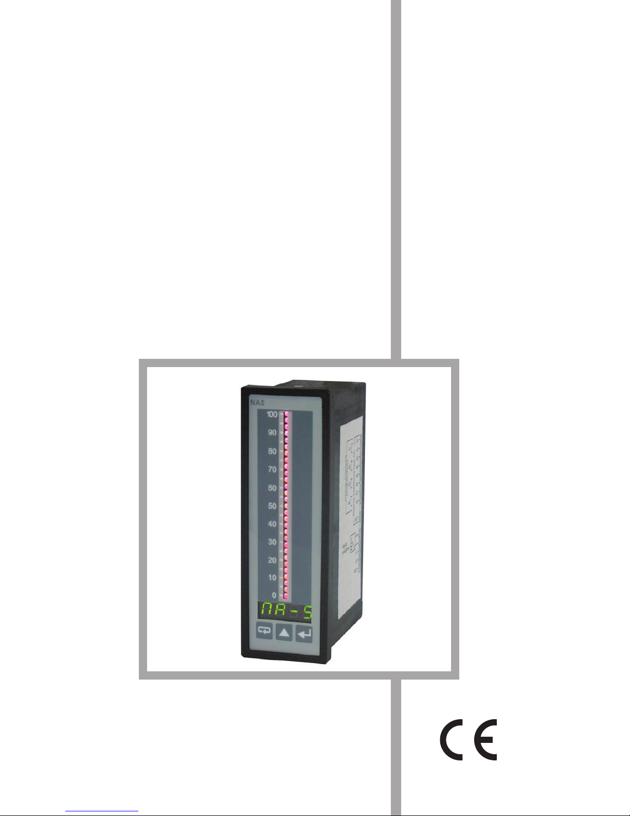
Fig.1. View of the NA5 meter.

6
NA5 meters can have in option: a continuous analogue output, a relay output, open
collector (OC) type outputs and an RS-485 digital output.
They are programmed by means of the keyboard and through RS-485.
NA5 meters realise following functions:
– measurement of the input quantity and displaying it on the display and the
bargraphs,
– recounting of the input signal into indication on the base of the individual
linear characteristic,
– arithmetical functions: raising to a power, extraction of roots,
– programming of colours and bargraph resolutions,
– signalling of alarm value setting exceedings,
– recording of the measured signal in programmed time segments,
– storage of maximal and minimal values,
– programming of the measurement averaging time,
– programming of the indication resolution,
– deadlock of the parameter introduction by means of a password,
– conversion of the measured quantity into a voltage or current output signal,
– service of the RS-485 interface in MODBUS protocol, both in ASCII
and RTU mode.
2. SET OF THE NA5 METER
We deliver in the set:
- NA5 meter 1 pc.
- user’s guide 1 pc.
- guarantee card 1 pc.
- plug with screw terminals 1 or 2 pcs (depending on execution)
- holders to fix the meter in the panel 2 pcs
- set of stickers with units 1 pc.
When unpacking the meter, please check whether the type and execution code
on the data plate correspond to the order.
7
3. BASIC REQUIREMENTS, SAFETY INFORMATION
Symbols located in this service manual mean:
WARNING!
Warning of potential, hazardous situations. Especially important. One must
acquaint with this before connecting the NA5 meter. The non-observance
of notices marked by these symbols can occasion severe injuries of the
personnel and the damage of the instrument.
CAUTION!
Designates a general useful note. If you observe it, handling of the meter is made easier. One must take note of this when the instrument is
working inconsistently to the expectations.
Possible consequences if disregarded !
In the security scope the meter meets the requirements of the EEC
Low-Voltage directive (EN 61010 -1 issued by CENELEC).
Remarks concerning the operator safety:
1. General
The NA5 meter is destined to be mounted on a panel.
Non-authorized removal of the required housing, inappropriate use, incorrect
installation or operation creates the risk of injury to personnel or damage to
equipment. For more detailed information please see the user’s guide.
All operations concerning transport, installation, and commissioning as well as
maintenance must be carried out by qualified, skilled personnel and national
regulations for the prevention of accidents must be observed.
According to this basic safety information, qualified, skilled personnel are
persons who are familiar with the installation, assembly, commissioning, and
operation of the product and who have qualifications necessary for their
occupation.
2. Transport, storage
Please observe the notes on transport, storage and appropriate handling. Observe
the climatic conditions given in Technical Data.
3. Installation
The NA5 meter must be installed according to the regulation and instructions
given in this user’s guide.

8
Ensure proper handling and avoid mechanical stress.
Do not bend any components and do not change any insulation distances.
Do not touch any electronic components and contacts.
Instruments may contain electrostatically sensitive components, which can easily
be damaged by inappropriate handling.
Do not damage or destroy any electrical components since this might
endanger your health!
4. Electrical connection
Before switching the meter on, one must check the correctness of connection
to the network.
In case of the protection terminal connection with a separate lead one must
remember to connect it before the connection of the instrument to the mains.
When working on live instruments, the applicable national regulations for the
prevention of accidents must be observed.
The electrical installation must be carried out according to the appropriate
regulations (cable cross-sections, fuses, PE connection). Additional
information can be obtained from the user’s guide.
The documentation contains information about installation in compliance with
EMC (shielding, grounding, filters and cables). These notes must be observed
for all CE-marked products.
The manufacturer of the measuring system or installed devices is responsible
for the compliance with the required limit values demanded by the EMC
legislation.
5. Operation
Measuring systems including NA5 meters must be equipped with protection
devices according to the corresponding standard and regulations for
prevention of accidents.
After the instrument has been disconnected from the supply voltage, live
components and power connections must not be touched immediately because
capacitors can be charged.
The housing and the door must be closed during operation.
6. Maintenance and servicing
Please observe the manufacturer’s documentation.
Read all product-specific safety and application notes in this user’s guide manual
9
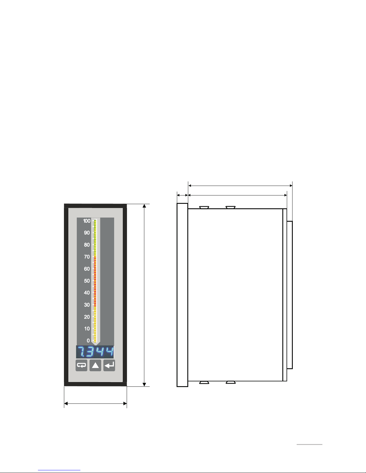
Fig. 2. Meter overall dimension
Before taking the meter housing out, one must turn the supply off.
The removal of the instrument housing during the guarantee contract period
may cause its cancellation.
4. INSTALLATION
4.1. Fitting
Prepare a (44
+0.5
x 137.5
+0.5
) mm hole in the panel. The thickness of the material
from which the panel is made should be in the range 1...45 mm.
The meter has screw terminal strips which enable the connection of 2.5 mm
2
cross-
section external conductors.
Meter dimensions are shown on the fig. 2.
48
144
77
max92
8

10
4.2. External connection diagrams
The description of terminal strips are shown on the fig. 3a.
Connections of input signals are shown on the fig 3b and output signals on fig.
3c and 3d.
The meter has programmable inputs. Maximal measuring ranges are given on
figures.
a/ Description of the terminal strip
6
1
2
5
3
4
12
7
8
11
9
10
15
14
13
21
17
20
18
19
27
22
23
26
24
25
30
29
28
1632
31
A1
A3
A5
A7
RS-485
A
B
GND
A2
A4
A6
A8
A1
A3
A5
A7
GND
E
Resistance thermometer
Power supply
Analogue
output
8 OC outputs
4 rela outputs
Supply of object
transducers
24Vd.c.
GND
5A
40 mA
600 V
Thermocouple or 300 mV
voltage from shunt
11
5 A current input
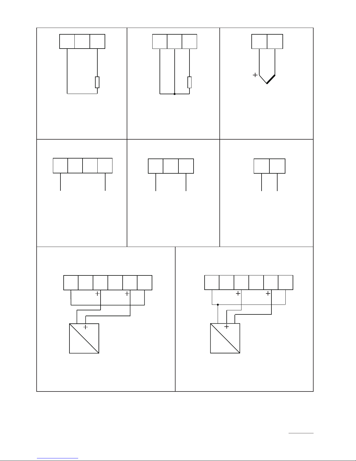
b/ Connection way of input signals
Resistance thermometer
in two-wire system or
resistance measurement
Resistance thermometer
in three-wire system
Thermocouple
or
300 mV voltage
600 V voltage input 40 mA current input
Two-wire object transducer
Three-wire object transducer
321
321
32
-
543 6
543
43
-
-
-
-
145 133
-
-
-
-
145 133
S
40 mA 40 mA
24 V d.c. 24 V d.c.
GND
600 V
GND GND
40 mA 5 A
12
Taking into consideration electromagnetic interference it is recommended to use
shielded conductors for the connection of input and output signals.
The power supply must be connected by means of a two-wire conductor with
a suitable cross-section ensuring its protection by means of an installation fusible
cut-out, in case of a short-circuit. Requirements concerning the supply cable are
regulate by EN 61010-1 p.6.10 standard.
Fig.3 External connections of the NA5 meter
8 outputs of OC type
4 relay outputs
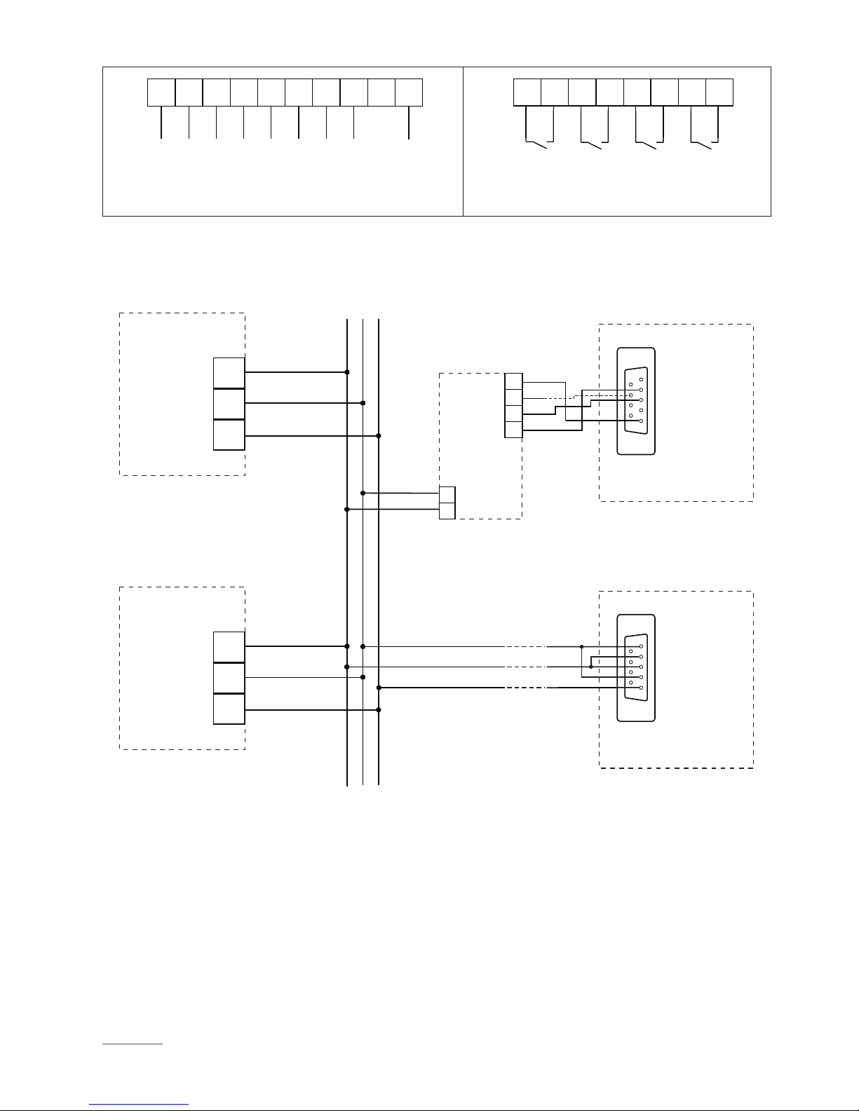
c/ Connection way of digital and analogue output signals depending on the
execution code
27 2326 242530 29 2832 31
A1 A2
A3 A4 A5 A6 A7 A8 GND
27 26 2530 29 2832 31
A1
A3 A5 A7
...
A
GND
B
B
A
GND
GND
A
B
RTS
RxD
TxD
DB9
6
1
9
5
DB9
6
1
9
5
19
17
18
NA5 Meter
19
17
18
NA5 Meter
IBM PC computer
IBM PC computer
with an RS-485 card
10
11
12
13
8
9
PD5
d/ Connection way of the RS-485 interface
13
5. SERVICING
After connecting external signals and switching the meter on, its name and
also the current version of the program, e.g.
n100. are displayed.
After ca 3 seconds, the meter transits automatically into the working mode in which
it carries out the measurement and the display of the measured value on the display
and the bargraph.
Depending on alarm parameter settings, the resolution and bargraph type, alarm
thresholds are also displayed on the bargraph.
The meter blanks automatically insignificant zeros.
Key functions:
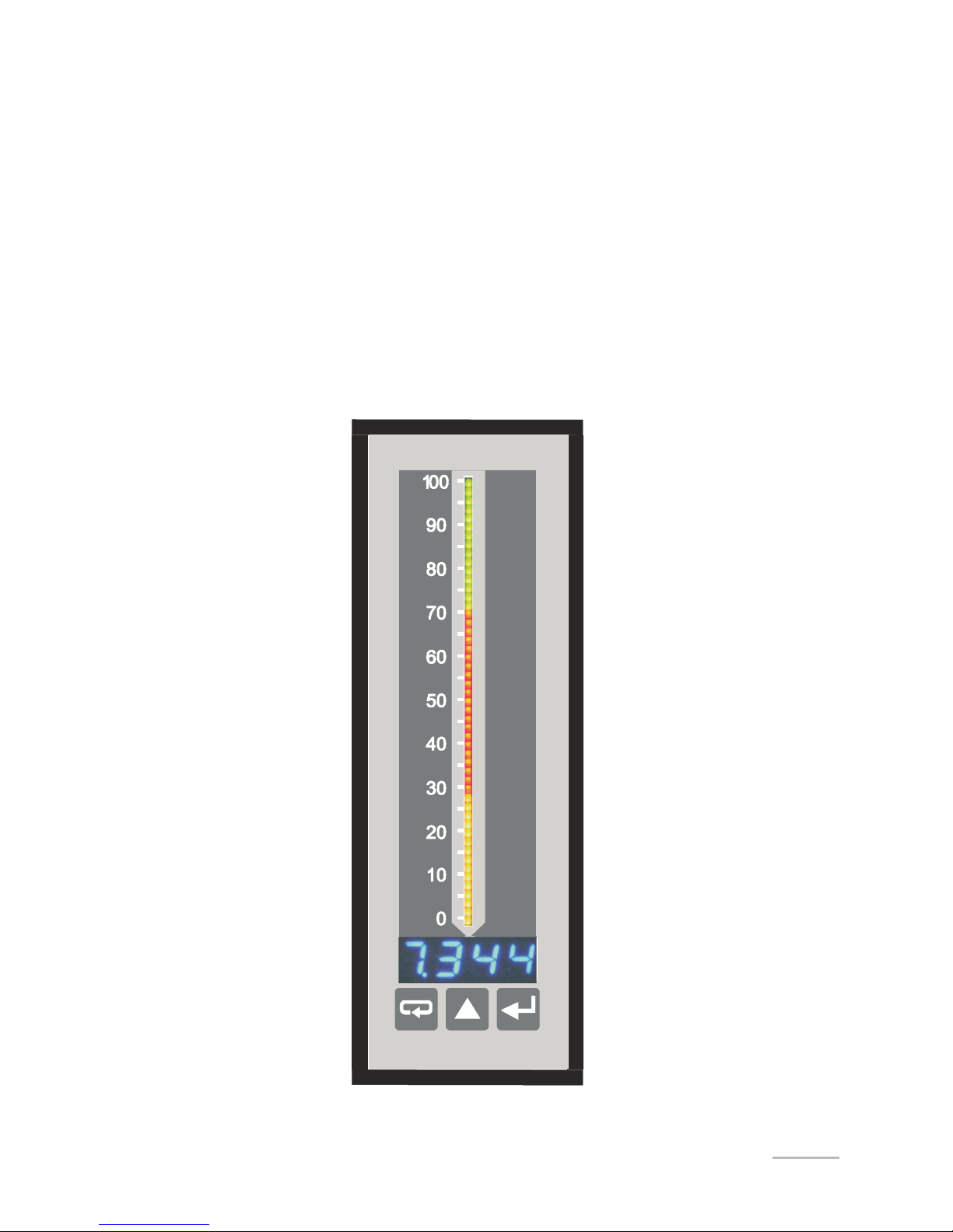
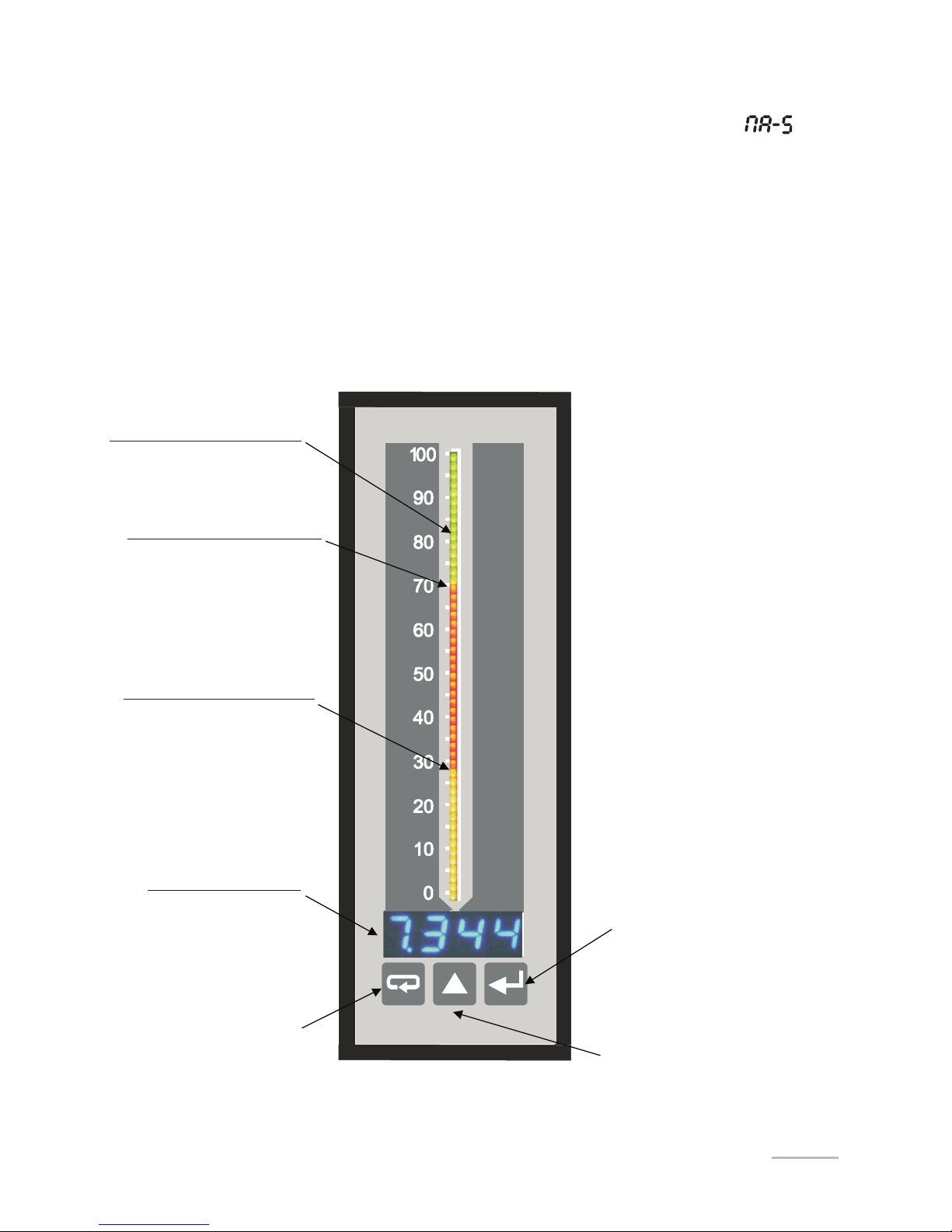
Fig. 4 Description of the NA5 frontal plate.
55-element bargraph (in
three-colour execution)
Upper alarm threshold
Lower alarm threshold
Display
Escape key
Acceptation key
Value increasing key
29-element bargraph (in
seven-colour execution)
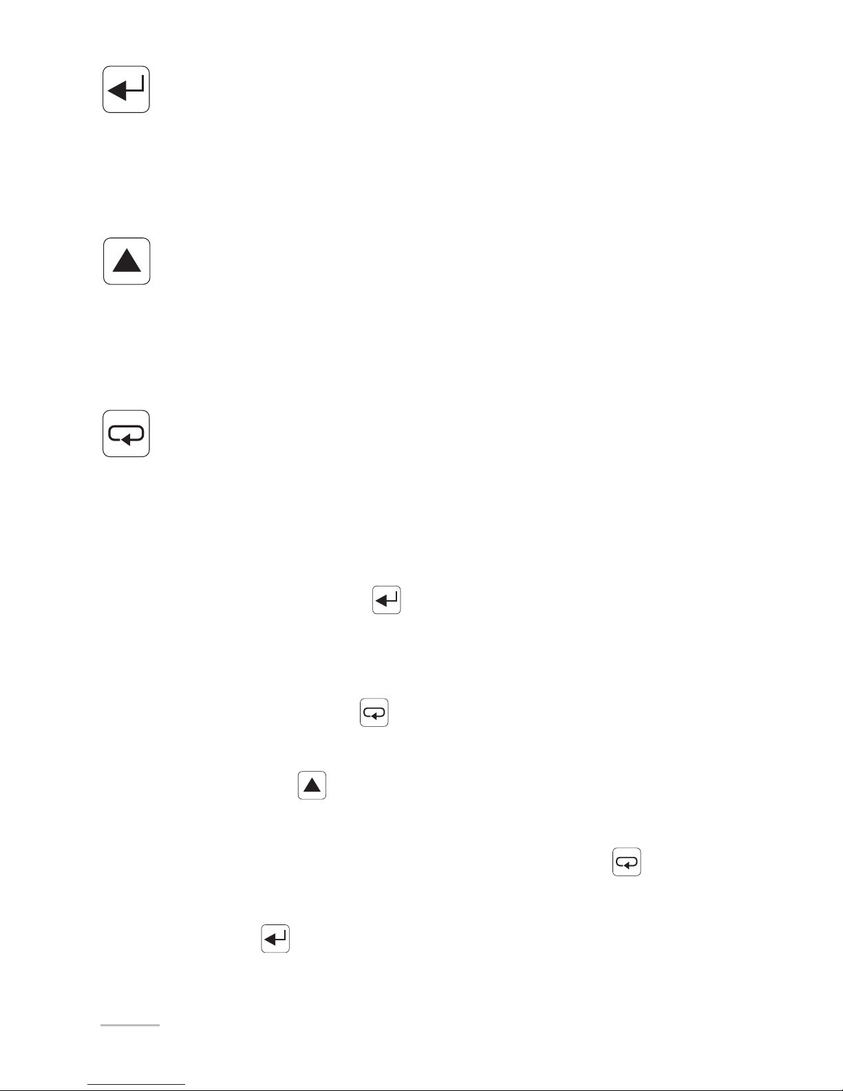
14
- acceptation key
- entry into the programming mode (hold down during ca 3 seconds),
- entry into the chosen parameter level,
- entry into the changing mode of the parameter value,
- acceptation of the changed parameter value.
- Key to increase the value
- display of the minimal value (first pressure), maximal (second pressure),
return to measurement (third pressure),
- mowing on the preview menu or programming matrix,
- change of the chosen parameter value - increasing of the value.
- Escape key
- entry into the menu of recording results,
- entry into the preview menu or programming matrix,
- exit from the preview menu or programming matrix,
- escape from the parameter change.
The pressure and hold down the
key during 3 seconds causes the entry into
the programming mode. The programming mode is protected by the seC safety
code.
The pressure and hold down the
key during 3 seconds causes the entry into the
preview menu and the menu of recorded values. One must move on the preview
menu by means of the key. In this menu, only all programmed parameters
except servicing parameters, are accessible to readout.
The exit from the preview menu is operated by means of the key. It is also
possible in the preview menu to review recorded resl values.
The pressure of the key on the resl parameter causes the entry into the pre-

15
view menu of recorder values. The recorded result number is displayed alternately
with the value e.g. n320/2174.
The moving on recorded values follows by means of the key. The pressure of
this key longer than ca 2 seconds will cause the acceleration of the review. The
pressure of the key in any moment will cause the lighting of the number of
recorded results. The exit from the review of recorded values is operated by means
of the key.
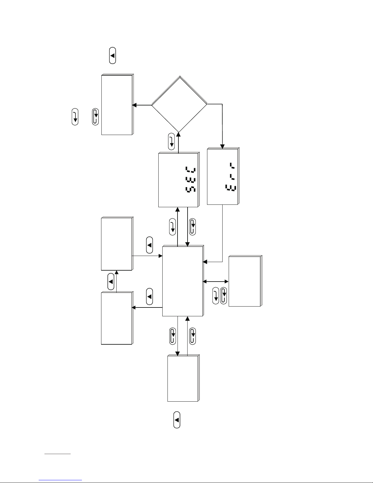
The algorithm of the meter servicing is presented on the fig. 5.
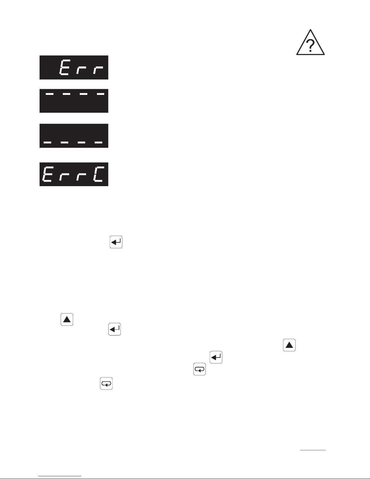
The appearance of the following symbols and inscriptions on the
display means:
16
Fig 5. Servicing algorithm of the NA5 meter.
3 sec
3 sec
-
Display of
the minimal
value
Measurement
Display of
the maximal
value
Password
introduction
mode
Programming
matrix
Check
the
password
Erasing
of alarm
outputs
Preview
menu
Moving on the
preview menu
Moving on the
matrix
Exit from the matrix
- Entry into the selected level
- Entry into parameter changes
Incorrect
Correct
Display of the
inscription
Monitoring of programmable
meter parameters
Monitoring of recorded
measured values
17
It is possible to change meter parameters:
- from the meter keyboard ( p 5.1)
- through RS-485 (p.6.)
5.1. Change of the NA5 meter parameters from the keyboard
The pressure of the key during circa three seconds causes the display
of the seC.
Inscription alternately with the set zero value by the manufacturer. The intro-
duction of the correct code causes the entry into the programming mode. The fig.6
represents the transition matrix into the programming mode. One can move on
groups of main parameters eg: Ch1, Ch2, bAr1, bAr2, Al1, Al2, etc, by means
of the key.
The pressure of the key on the given level, causes the entry into parameters of
this level. The moving on the given level is operated by means of the key.
In order to change the value, one must use the key. In order to escape from
the parameter change, one must press the key.
By means of the key, one can exit from the selected level and programming
matrix to the measurement.
Incorrectly introduced safety code
Exceeding of the upper measuring range or
lack of sensor
Exceeding of the lower measuring range or
short-circuited sensor
Error of the conductor resistance compensation. No
connected conductor or damaged conductor.
18
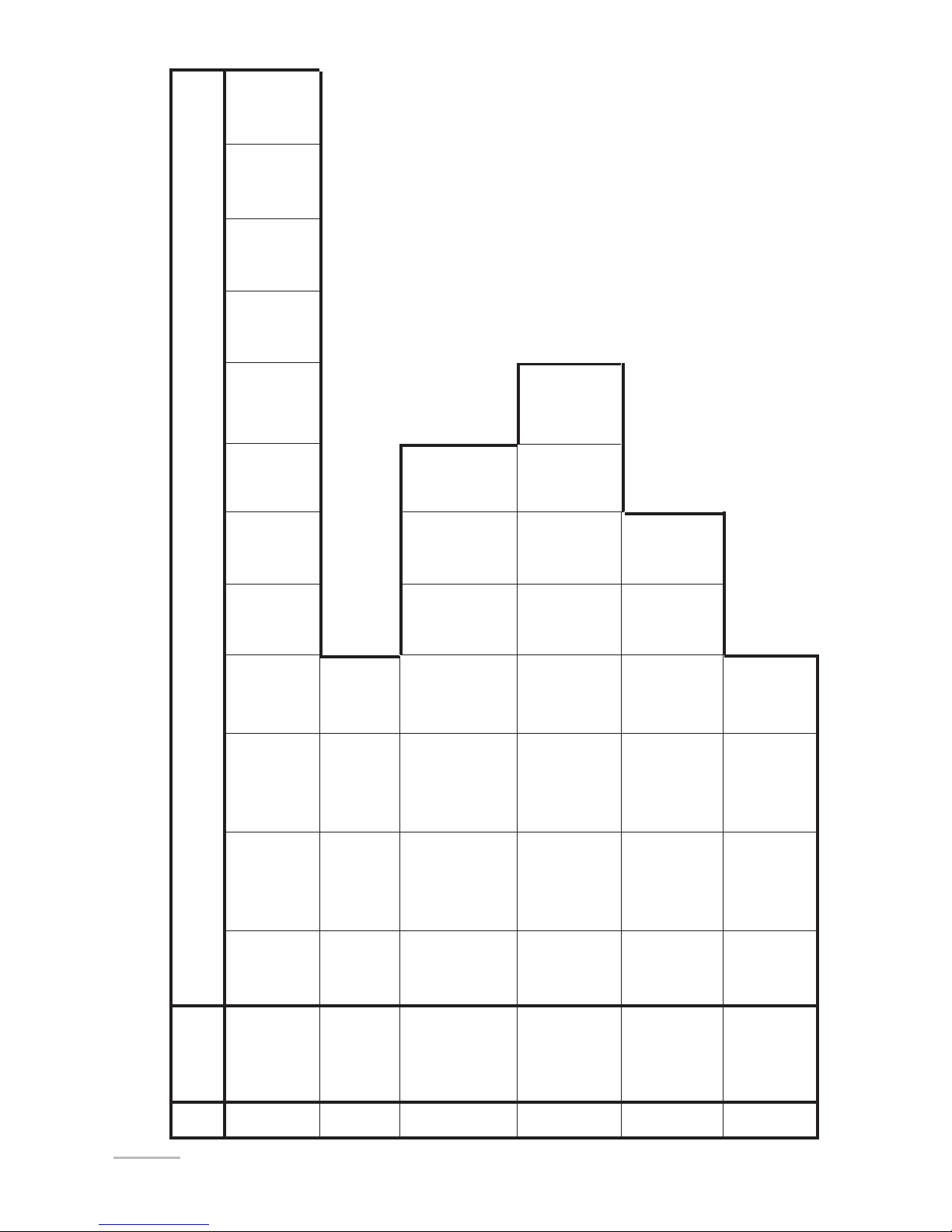
Fig. 6. Transition matrix into the programming
mode
Parameters of the selected level
Lev.
Nr
Main
menu
Bargr.
type
Bargr.
colour
Lower
bargr.
Upper
bargr.
Input
indiv.
charac.
Baud
rate
Kind of
transm.
Device
adress
Param.
inscript.
Passw.
change
Test of
display +
bargr.
Time
change
Erasing
of min.
value
Erasing
of max.
value
Record. Chan.1
record.
start
Upper
threshold
Alarm
delay
Alarm
support
Lower
marker
colour
Upper
marker
colour
Param.
indiv.
charac.
Param.
indiv.
charac.
Param.
of indiv.
charac.
1
2
3
11
12
13
barg
l0gr
Chn
al8
al1
10
ser
0ut
typb
typ
reC
set
Input
type
÷
÷
lo:n
Lower value
of input range
Hi:n
Upper value
of input range
func
Mathem.
func.
Con
Kind of
comp.
d_p
Decim.
point
Cnt
Meas.
time
colr brl brH
prl
Lower
threshold
prH typa
Alarm
type
dly H0ld Curl CurH
:nd0 d_H1 d_H20_y1 0_y2
Param.
of indiv.
charac.
baud tryb adr
seC tst Hour Clrl ClrH
gor1 dat1 :nt1
Chan.1
record.
date
Chan.1
record.
interv.
:nd:
Input ind.
charact.
:_H:
Param.
of ind.
charact.
Param.
of ind.
charact.
d_y: :_H2 d_y2
Param.
of ind.
charact.
Param.
of ind.
charact.
19
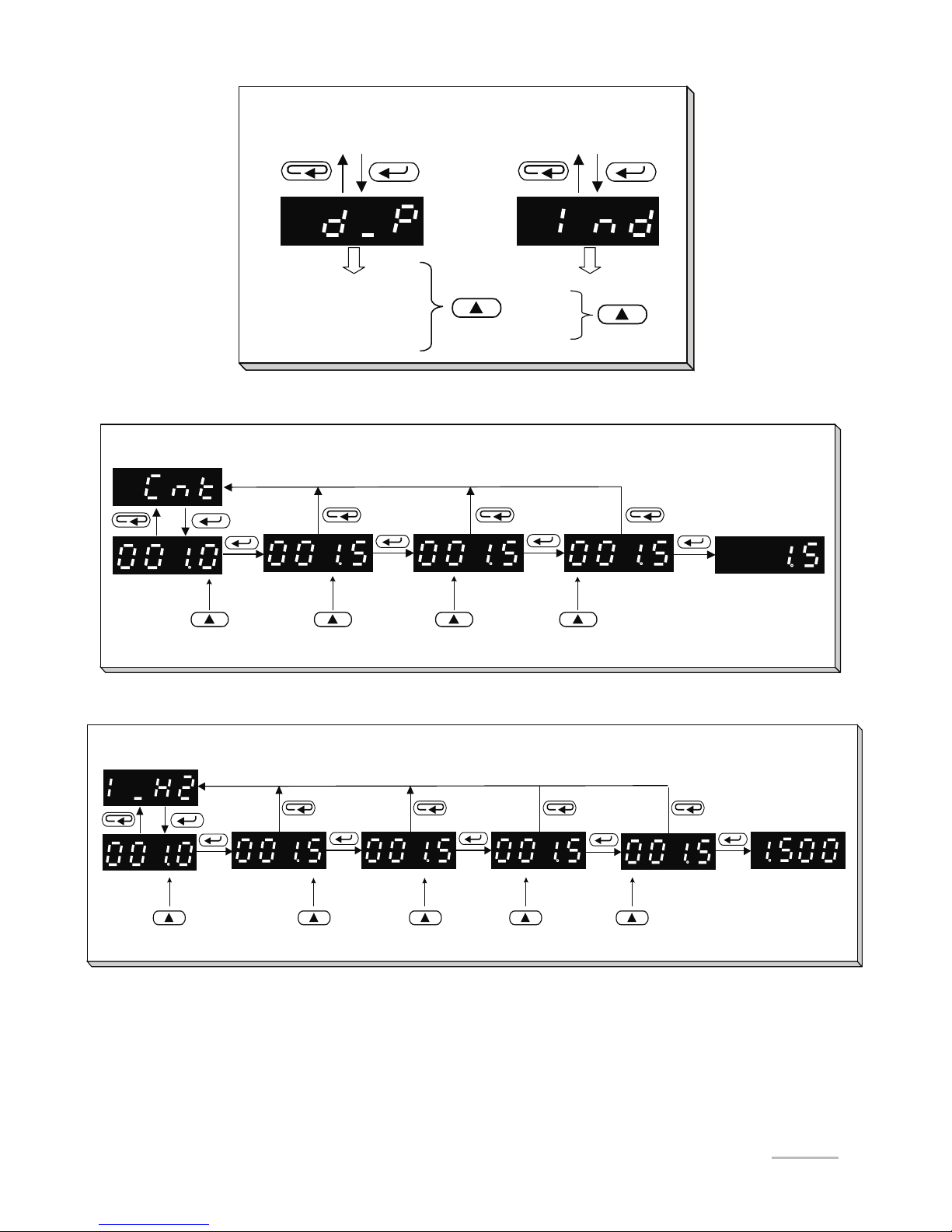
0000
000.0
00.00
0.000
Auto
On
Off
Examples of value changing of the
chosen parameter (parameter-symbol)
Change of the
flickering position
Change of the
flickering position
Change of the
flickering position
Blanking of
insignificant
zeros
Change of the
flickering position 0-9, -, -1
Example of value changing of the chosen parameter
without changing of the decimal point (number parameter)
Adjustment
of the decimal
point
Change of the
flickering position
Change of the
flickering position
Change of the
flickering position
Change of the
flickering coma
Change of the
flickering position 0-9, -, -1
Example of value changing of the chosen parameter
with changing of the decimal point (number parameter)
Fig. 7.
Meter programmable parameters are presented in the table 1. The programming of
parameters is possible after the previous introduction of the password.
 Loading...