

Page 1

Page 2

TABLE OF CONTENTS
Bow Owner’s Personal Record . . . . . . . . . . . . . . . . . . . 2
Compound Bow Terminology . . . . . . . . . . . . . . . . . . . 3
Important Safety Information . . . . . . . . . . . . . . . . . . . 4
Compound Bow Maintenance
Strings and Cables . . . . . . . . . . . . . . . . . . . . . . . . . . . . . 6
Eccentric Lubrication . . . . . . . . . . . . . . . . . . . . . . . . . . . 7
Bow Press Use . . . . . . . . . . . . . . . . . . . . . . . . . . . . . . . . . 7
Initial Compound Bow Setup
Rest Selection . . . . . . . . . . . . . . . . . . . . . . . . . . . . . . . . . 9
Nock Set Installation . . . . . . . . . . . . . . . . . . . . . . . . . . . .10
Cable Guard Installation . . . . . . . . . . . . . . . . . . . . . . . . .11
Tiller Adjustment . . . . . . . . . . . . . . . . . . . . . . . . . . . . . . .12
Centershot . . . . . . . . . . . . . . . . . . . . . . . . . . . . . . . . . . . .13
Arrow Fletch Clearance . . . . . . . . . . . . . . . . . . . . . . . . .14
Compound Bow Adjustment
Draw Weight Adjustment . . . . . . . . . . . . . . . . . . . . . . . .14
Cam & 1/2 Draw Length Adjustment . . . . . . . . . . . . . .15
Optimizing Cam & 1/2 Performance . . . . . . . . . . . . . .16
Zephyr Cam & 1/2 . . . . . . . . . . . . . . . . . . . . . . . . . . . . . 18
Optimizing Zephyr Cam & 1/2 Performance . . . . . . . . .19
Optimizing Spiral Cam & 1/2 Performance . . . . . . . . . 20
Wheel & 1/2 Draw Length and Optimization . . . . . . .21
Wheel & 1/2 Optional Draw Stop . . . . . . . . . . . . . . . . .23
Versa Cam & 1/2 Draw Length Adjustment . . . . . . . . .23
Versa Cam & 1/2 Control Cable Removal . . . . . . . . . .25
Locating Your Bow’s Serial Number . . . . . . . . . . . . . .26
Tuning Your Compound Bow . . . . . . . . . . . . . .27
Compound Bow Warranty . . . . . . . . . . . . . . . . . . . . . . .27
Page 3

1
INTRODUCTION
Welcome to the Hoyt family!
As a member of an elite team, you will be
pleased to know that you have purchased the
finest crafted, most dependable bow on the
market. Only the finest components go into
every Hoyt bow along with 75 years of experience in bow technology and manufacturing.
With some basic maintenance your new bow
will provide you with years of good shooting
and dependable service.
543 North Neil Armstrong Road
Salt Lake City, Utah 84116-2887
(801) 363-2990 phone
(801) 537-1470 fax
www.hoyt.com
Page 4
2
BOW OWNER’S PERSONAL RECORD
Fill in the following Personal Bow Record for
your later reference.
Bow Serial Number
Hoyt Bow Model
Purchased From
Purchase Date
Draw Length “ Draw Weight #
String Length “ Buss Cable Length “
Control Cable Length “
Important Notes:
Save your sales receipt and serial number for your
bow. The sales receipt, as well as your serial number,
is your proof of date-of-purchase. Proof of date-ofpurchase will be required should your bow ever
need warranty service. The following space has been
reserved for you to staple or tape your sales receipt for
safe and convenient keeping.
IMPORTANT!
Staple or tape your sales receipt
here for safekeeping.
See page 26 for information on where your bow serial number is located.
Page 5
3
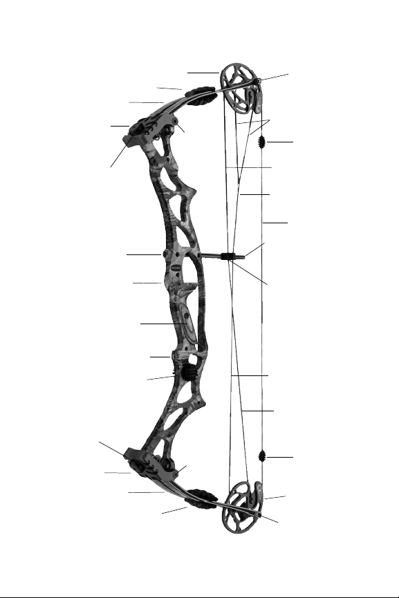
COMPOUND BOW TERMINOLOGY
Top Cam
Bottom Cam
Limbs
Buss Cable
Limb Weight
Adjustment
Bolt
Weight
Locking
Screw
Sight Window
Bow String
Cable Guard Bar
Cable Guard
Glide
Riser
Stabilizer Bushing
Weight
Locking
Screw
Limbs
Limb Weight
Adjustment
Bolt
Axle
Axle
Limb Pocket
Limb Pocket
Control Cable
Buss Cable
Control Cable
Yoke
Grip
StringShox
AlphaShox
StringShox
AlphaShox
RizerShox
Page 6

WARNING!
YOU’RE RESPONSIBLE FOR ARCHERY SAFETY
Please read the following safety information.
Disregarding these rules may cause serious injury to
yourself, others, or property.
1. NEVER “DRY FIRE” YOUR BOW. Dry fire means
to draw and release the bowstring without an arrow.
Firing a bow without an arrow to absorb the energy
can cause severe damage to your bow and possible
injury to the shooter or others nearby. Let-down the
bow slowly and carefully from any drawn position.
2. NEVER EXPOSE YOUR BOW TO EXTREME
H E AT OR PROLONGED EXTREME DAMP.
Excessive heat, such as that experienced on a sunny
day inside a closed vehicle, could cause limb failure.
Prolonged storage in a hot dry attic or damp basement
could also be damaging. Store the bow properly
when it is not in use.
3. CAREFULLY INSPECT YOUR BOW BEFORE
EACH USE. Carefully note the condition of the bow-
string, limbs and riser before you shoot. Frayed bowstrings should be replaced. Damaged or suspect
limbs should be reported to your local dealer for
inspection or replacement.
4
Page 7

5
4. BE SURE OF YOUR BACKSTOP. Make sure that
the backstop you use is large enough to catch a stray
arrow and that it is thick enough that the arrow cannot completely penetrate it. Make sure that it is positioned in a safe direction away from dwellings and
other people.
5. BE SURE OF YOUR TARGET. Make sure that there
are no persons, livestock, buildings or other objects
behind or near your target. Be absolutely sure of your
target in low light conditions.
6. INSPECT ALL ARROWS. Before shooting, inspect
your arrows for defects. Discard cracked or dented
shafts. Replace damaged or loose fletching and nocks.
7. ALWAYS BE SAFE. Never shoot straight up. Wear
safety glasses when working on and shooting your
bow. Be careful around strings and cables when using
broadheads. Cutting strings and cables can cause
serious damage to your bow and possible injury to
you or others. Do not draw the bow beyond its maximum draw length. Never point or aim a drawn bow
at another person. Children must be supervised by an
adult.
8. READ AND HEED ALL WARNINGS. Hoyt cannot
be held responsible for injuries suffered or caused by
misuse, unsafe or improper arrow and bow combinations. Hoyt cannot be held responsible for injuries
sustained when using an altered or modified Hoyt
bow.
Page 8

6
WARNING
This bow is a deadly weapon.
Always abide by all safety advisements.
Children must be supervised by an adult.
COMPOUND BOW MAINTENANCE
Your bow is a mechanical device and as such, is subject to wear and need of periodic inspection, adjustment and service. Hoyt recommends that you take
your bow to a Hoyt authorized pro shop at least once
a year for a yearly professional maintenance and
inspection. Areas to be inspected are axles, spacers,
lubrication of axle bushings (Hoyt Cam & 1/2 System
bows do not require axle bushing lubrication), e-clips,
strings, cables, limbs and riser.
The following information provides helpful instruction on the proper care and maintenance of your new
Hoyt bow. Keep this manual as a handy guide for
future reference.
STRINGS AND CABLES
Apply a light coat of bowstring wax to your bow’s
cables and string on a regular basis. Hoyt suggests
once every two weeks during peak use. Use a high
quality bowstring wax available at your local Hoyt
pro shop. This will keep your bow’s strings and
cables in good condition. To assure best results
replace your string and cables when wear is evident
or every two years under normal use conditions.
Page 9

7
Insist that Hoyt string and cables be used on your
bow. Some Hoyt bow models come equipped with
the FUSE Custom String System. In those cases,
always replace your strings with FUSE brand strings.
Beware of lesser quality string and cables as they may
alter the performance of your bow or cause damage to
it.
ECCENTRIC LUBRICATION
Cam & 1/2 System bows feature sealed ball bearings
which do not require lubrication.
For conventional bearings or bushings, a light spot
lubrication of the axles where they pass through the
eccentric should be done on a regular basis (1,500 2,000 shots). In adverse hunting conditions where
dirt, dust or moisture are encountered, lubrication
may be done on a daily basis. Hoyt recommends you
use a silicone or Teflon based lubrication or any other
quality grease available at your local Hoyt Pro Shop.
It is not recommended that you use “Penetrating Oils”
such as WD-40, EZ-#7, Fast Break, etc.
BOW PRESS USE
Never allow your bow to be put into a bow press
unless it is operated by a knowledgeable bow technician. Hoyt recommends that all necessary adjustments requiring the use of a bow press be done by an
authorized Hoyt pro shop.
Page 10
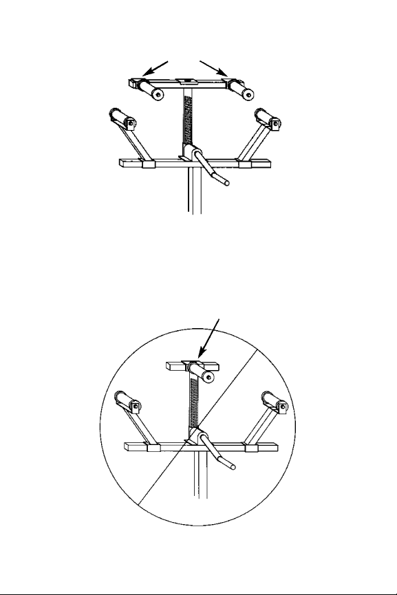
fig 1 (An Example of a Double Pull Bow Press)
Always use a double bow press like that shown
in figure 1 when working on your bow. Never
use a single pull bow press. (See fig 2)
8
Presses the bow in two places
Presses the bow at the grip only
fig 2 (An Example of a Single Pull Bow Press)
Page 11
9
COMPOUND BOW SETUP
REST SELECTION
There are three basic types of arrow rests: Shoot
Through, Fall Away, and Shoot Around. Hoyt
recommends that you seek the advice of a qualified pro shop for the proper rest selection for
your style of shooting.
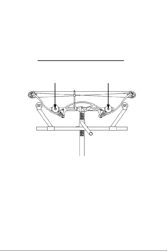
Before putting your bow in a bow press, loosen
both the top and bottom weight lock screws and
weight adjustment bolts 5 to 7 turns from maximum weight (when limb bolts are fastened all the
way down). When putting your bow in the
press, never put pressure on the riser! Always
position the rollers at the base of the limbs (where
the limbs enter the limb pockets). (See fig 3)
fig 3
Page 12
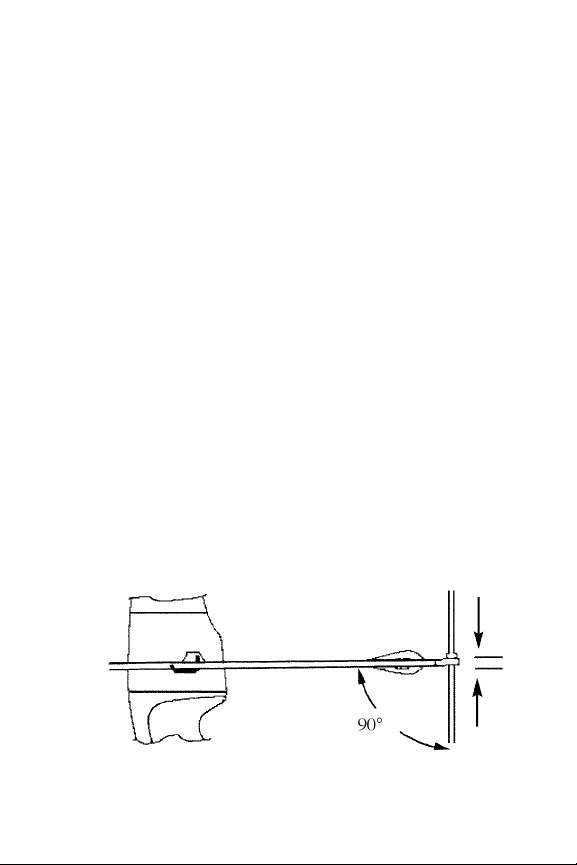
NOCK SET INSTALLATION
A nock point is a reference on the string that
marks the exact location for you to nock your
arrow. The arrow’s nock is positioned under the
nock set. To install the nock set at the proper
position begin by slipping the nock set on the
string. Then, using your rest as a reference, position the nock set just above level. A finger shooter should initially position the nock set at
approximately 3/16” above level. The release
shooter should position the nock set so that the
arrow sits at a 90 degree angle with the string
and adjust height as needed. (See fig 4) Once the
nock set is at the desired location use a special set
of nocking pliers to crimp the nock set into place.
NEVER shoot a bow without a nock set or with a
nock set that has not been properly crimped. For
proper installation Hoyt recommends that this be
done by a qualified pro shop.
10
Nocking Point
Height
fig 4
Page 13
11
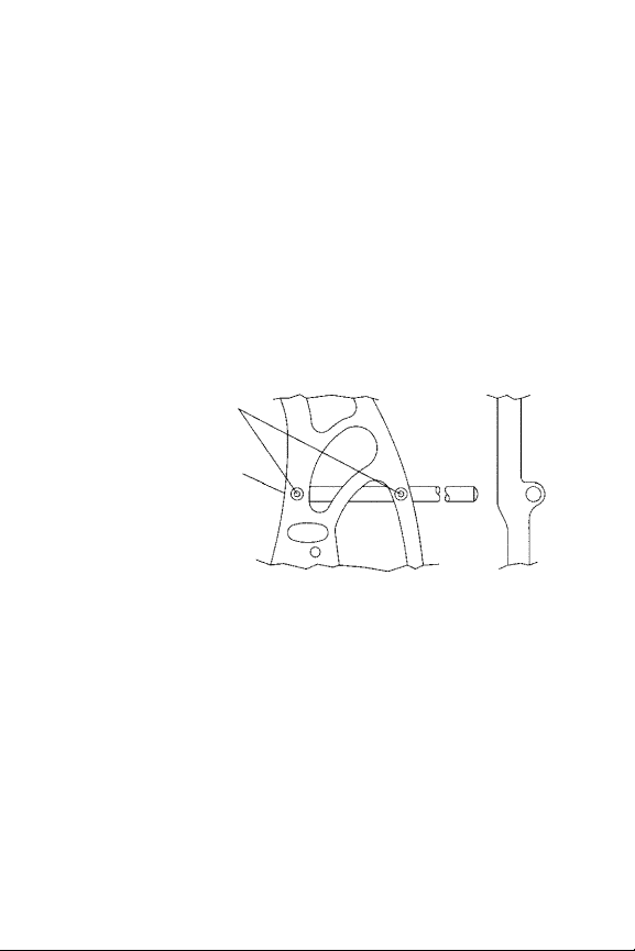
C A B L E G U A R D I N S T A L L AT I O N
All Hoyt bows are designed with a built in cable
g u a r d bar attachment. Before mounting the cable
g u a r d bar, you must remove the ru b b e r b a n d s
used only for shipping purposes. To insert the
cable guard bar, simply slide the bar through the
two mounting holes on the riser making sure that
the bar is pushed completely through and flush
with the end of the front mounting hole. A f t e r
the bar has been inserted fasten with the 1/4-20 x
1/2” set screws provided. (See fig 5)
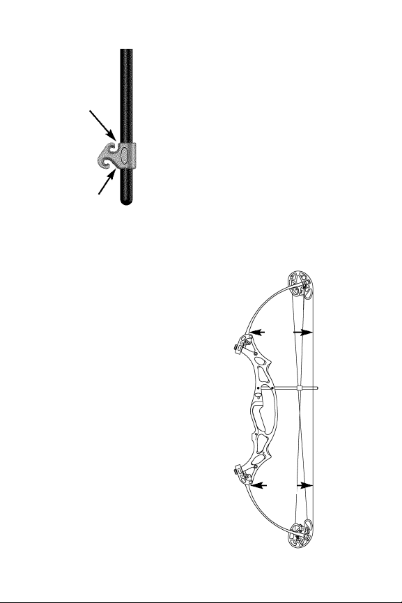
CABLE GUARD GLIDE INSTALLATION
To prevent your bow’s cables from ru b b i n g
against each other, Hoyt uses a specially
designed cable glide that has off-set cable slots.
To correctly install the glide on all Hoyt bows,
first place the glide on the cable guard bar. (See
fig 6) Next, push the control cable into the shorter front slot. Then, push the buss cable into the
longer rear slot. CAUTION: Do not pull bow
Screws
Flush w/Front of Riser
fig 5
Page 14
12
back without proper installation of cable guard bar and
glide.
TILLER ADJUSTMENT
Tiller is the difference in distance between the upper limb
to the string and lower limb to
the string measured from the
base of the limbs (where the
limb and riser meet) at a 90 degree angle to the
string. (See fig 6)
The main function of
tiller is to allow the
a r cher to more easily and
comfortably aim during
the draw and release of
the shot. Most bows will
shoot best near even tiller
which means the distance from the string to
the limb is the same on
top and bottom. Ti l l e r
adjustments are made by
adjusting either limb
weight adjustment bolt.
(See draw weight adjustment section pg. 14)
fig 6
Control
Cable
Buss
Cable
fig. 7
Tiller
Tiller
Page 15
13
Example: If you have too much tiller on the bottom limb, decrease the weight on the top limb or
i n c r ease the weight on the bottom. Hoyt re c o mmends that you initially set tiller equal top and
b o t t o m .
CENTERSHOT
Centershot is the alignment of the arrow in the
power path of the string. This is accomplished
by moving the arrow rest left or right. Release
shooters should line the arrow up with or just
slightly outside of the power path of the string.
(See fig 8) Finger shooters should position the
arrow so that the tip is just to the outside of the
power path of the string. (See fig 8)
Centershot is critical to how accurately a bow
will perform. These are initial centershot settings, for proper alignment Hoyt recommends
this be done by a qualified pro shop.
fig 8
Rest
Powerpath
Rest
Powerpath
Release Setting
Fingers Setting
Page 16
14
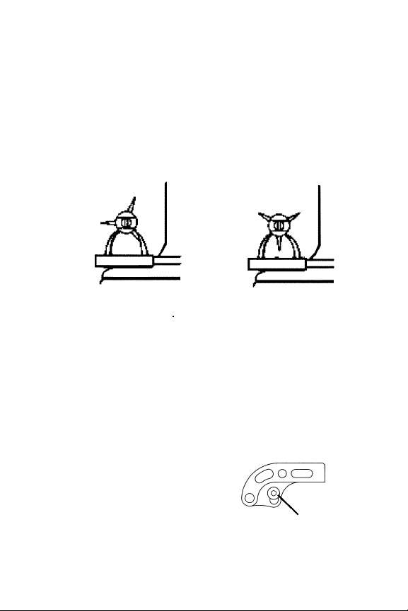
FLETCH CLEARANCE
Fletch clearance is the ability of your vanes or
fletchings to pass cleanly by or through your
arrow rest without impacting the rest so severely
that the arrow’s flight path is disrupted. It is necessary that you have adequate vane clearance to
achieve proper arrow flight. (See fig 9)
COMPOUND BOW ADJUSTMENT
DRAW WEIGHT ADJUSTMENT
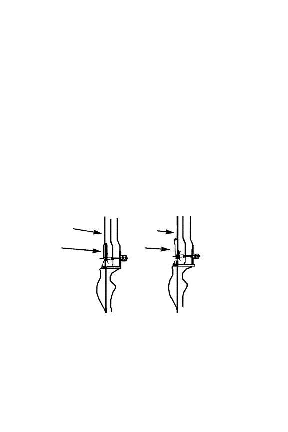
Weight adjustments can easily be made by turning the weight adjustment bolt clockwise to
increase weight or counter clockwise to decre a s e
weight. Note: Always turn the top and bottom
adjustment bolts in equal amounts. Some Hoyt
model bows are equipped
with a Dual Locking Pocket
System. Before draw weight
adjustments are made on
these models you must first
loosen the pocket locking
s c r ews located on both sides
Incorrect Correct
fig. 9
Pocket Locking Screw
fig 10
Page 17
15
of the pocket. (See fig 10) When adjustments are
completed, re-tighten the pocket locking scre w s .
D R AW LENGTH ADJUSTMENT (INNERCAM ADJUSTABLE MODULES)
Many Hoyt bows utilize the inner- c a m
adjustable module for draw length adjustment.
The inner-cam can generally be adjusted without
the aid of a bow press.
CAM & 1/2 DRAW LENGTH ADJUSTMENT
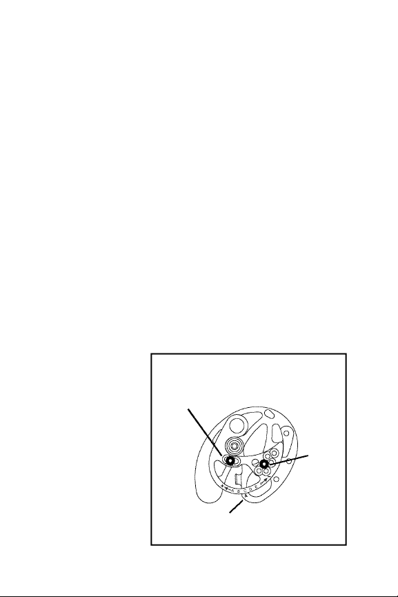
TOP CAM: To adjust the draw length on Hoyt’s
Cam & 1/2 (inner-cam) model bows, use a standard allen key to loosen the fastening screw and
to remove the draw length screw. (see fig 11)
Rotating the inner-cam in the (+) direction will
lengthen the draw. Rotating the inner-cam in the
(-) direction will shorten the draw. Each lettered
position will
provide approximately l/2 inch
l o n g e r / s h o r t e r
draw than the
p revious setting. Once the
inner-cam is in
the desired location, re i n s t a l l
and tighten the
fig 11
TOP CAM
Module Positioning
Indicator
Draw
Length
Screw
Fastening
Screw
Page 18
draw length screw first and then the fastening
screw.
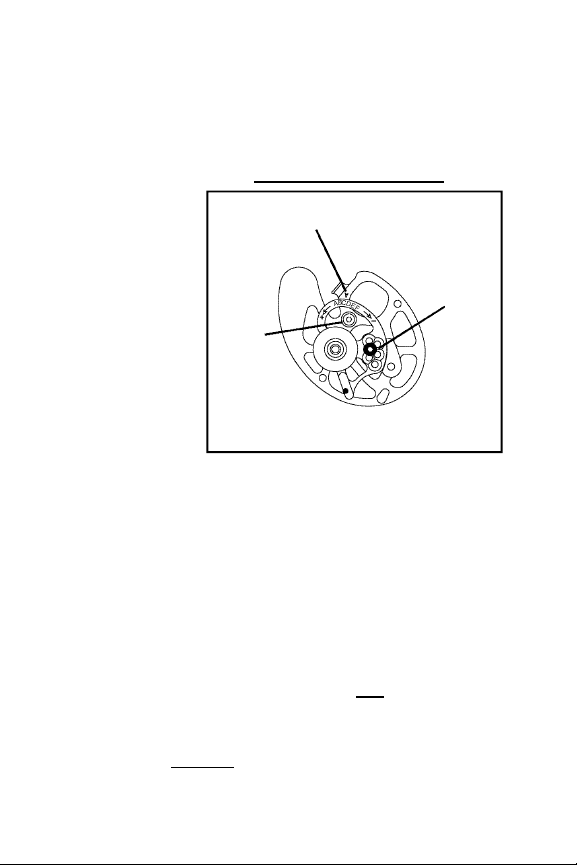
BOTTOM CAM: Remove the draw length screw,
rotate module to the same lettered position as the
top module,
and re p l a c e .
(see fig 12)
Note: Yo u
must make the
same adjustments to the
top and the
bottom innercams or the
bow will not
tune properly.
WARNING: Never remove the stainless steel
control cable peg unless the string is relaxed in
a bow press.
OPTIMIZING CAM & 1/2 PERFORMANCE
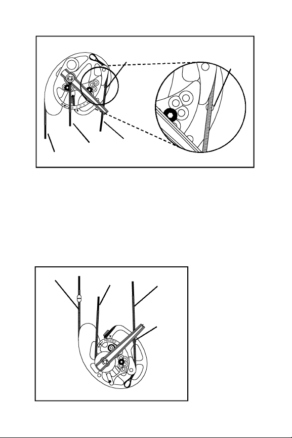
In order to verify the factory setting of your
adjustable Cam & 1/2 System bow you should
examine the cam's built-in re f e ren ce holes. When
viewing the module side of the t o p cam, at least
part of the control cable should lie over the re f e rence hole (see fig13). When viewing the module
side of the b o t t o m cam, at least part of the buss
16
fig 12
BOTTOM CAM
Draw
Length
Screw
Module Positioning
Indicator
Control
Cable
Peg
Page 19
17
cable should lie over the re f e r ence hole as shown
in fig 14. It is not necessary to have the cables
c e n t e red over the re f e ren ce holes. Module position will not affect the re f e rence hole location.
Due to various limb configurations, some 2005
and later models are optimized with the cables
slightly off the re f e rence holes. In these cases,
mark the cable locations on the cam (as shipped
f rom the fact o r y ) w i t h
p e r m a n e n t
ink. Use these
marks for
f u t u r e re f e r ence. The factory tune is
always optimized for perf o r m a n c e .
Bowstring
Buss Cable
Yoke
Control
Cable
Reference
Hole
Reference
Hole
fig 13
fig 14
TOP CAM
BOTTOM
CAM
Bowstring
Buss
Cable
Control
Cable
Reference
Hole
Page 20
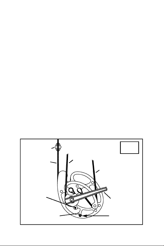
Zephyr Cam & 1⁄2
Hoyt's Zephyr Cam & 1⁄2 is a high performance draw
length specific cam system. Cams are available in 1⁄2
inch draw-length increments. Zephyr cams are also
available in either 65% or 80% ATA let-off. Both top
and bottom cams must be swapped out to change the
bow's let-off.
Adjustable Valley Technology (AVT)
The Zephyr Cam & 1⁄2 features AVT, which allows the
shooter to customize how the cam feels at full draw.
An optional draw stop peg is included. Without the
peg the back wall is softest and the cam will have the
longest valley. With the draw stop installed in the furthest outboard position the cam will feature a long valley and a hard wall. In the inboard peg position the
cam has a hard wall and a shorter valley. The draw
length and let-off are essentially the same with or
without the AVT draw-stop peg installed. (See fig 15)
CABLE
SIDE
Limb
Control
Cable
Buss Cable
Bowstring
StringShox
Stealth Draw
Dampener
Inboard
Peg Position
Outboard
Peg Position
fig 15
18
Page 21
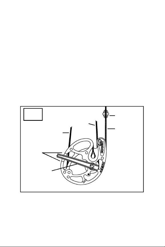
Zephyr Cam & 1/2 Optimization
Zephyr Cam & 1/2 features performance marks on the
bottom cam to indicate the optimum performance
range for the cam. The limb should lie somewhere
between the lines when the bottom cam is viewed
from the logo side at brace. (See fig 16) In some cases
the limb will not be exactly centered. This is by design
since each individual cam/limb combination is factory
optimized for performance and draw length. If draw
length adjustments are necessary, it is acceptable to
shorten strings or cables. You will retain excellent performance from your Zephyr Cam & 1/2 as long as the
limb lies anywhere within the performance marks.
STRING
SIDE
Buss Cable
Control
Cable
Bowstring
StringShox
Performance
Marks
Limb
fig 16
19
Page 22
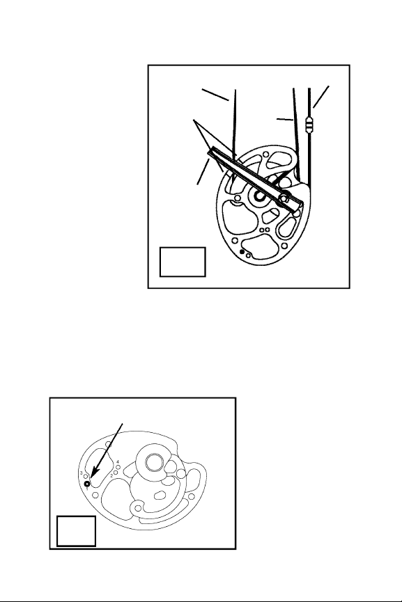
OPTIMIZING SPIRAL CAM & 1/2 PERFORMANCE
To verify factory
setting of bows
featuring Hoyt’s
Spiral Cam &
1/2 System, you
should examine
the cams’ builtin performance
marks. On both
the top and bottom cam, the
limb should lie
s o m e w h e re in
between the
marks. (See fig
17) It is not necessary to have the limb exactly cent e r ed between the marks. The let-off of your Spiral
Cam & 1/2 bow can be adjusted using a standard
allen key. The ATA l e t - o ff values of the Spiral Cam
& 1/2 System vary from 55% to 65%. You will notice
the four draw-stop holes on the bottom cam numb e red 1 through 4. (See fig 18) For the lowest let-off
(55%), the drawstop peg should
be placed in hole
#4. Place the drawstop peg in hole #1
for the highest leto ff (65%). Note:
Smaller cams may
have 2 or 3 holes.
CABLE
SIDE
fig 18
Draw Stop in Highest Let-off Position
fig 17
Performance
Marks
Buss Cable
Control
Cable
Bowstring
STRING
SIDE
Limb
20
Page 23
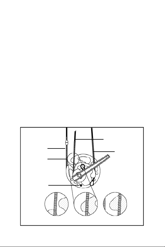
Simply remove the draw-stop peg from its original position, place it in the desired position, and
tighten. Each Hoyt Spiral Cam & 1/2 System bow is
shipped in the 65% let-off (draw stop peg position
#1). N o t e : changing the draw-stop position to
manipulate let-off will alter draw length by appro ximately 1/8” for each draw-stop hole. Draw length
will be shortened when changing to a lower let-off
position and lengthened in higher let-off positions.
WHEEL & 1/2 DRAW LENGTH & OPTIMIZATION
Hoyt’s Wheel & 1/2 system is shipped as a draw
length specific pair of eccentrics with an optional draw
stop. You may alter string and cable lengths as needed
to achieve your exact draw specifications. However,
excess string or cable twists will alter the peak draw
fig 19
BOTTOM
WHEEL
Optimum Performance Range
Optional
Draw Stop
Performance
Reference
Bowstring
Buss Cable
Control
Cable
21
Page 24
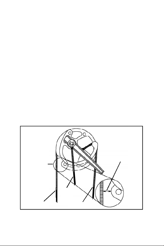
weight and may reduce the performance of the
wheels on your bow. Hoyt recommends staying
within the optimum performance range shown in
Figure 19. If your draw length requires a cam position well outside the range shown in Figure 20, you
may consider changing to a smaller or larger cam as
needed. Please consult your local authorized Hoyt
dealer. Start by setting the bottom wheel position as
shown in Figure 19. Next, approximately match the
distance on the top and bottom wheels between the
bowstring and the point of the wheels as shown in
Figure 20. (You may need to change the control cable
length to optimize the top wheel position.) Exact
measurements are not necessary since the Wheel &
1/2 system is not sensitive to timing and synchronization.
fig 20
TOP
WHEEL
Bowstring
Buss
Cable
Yoke
Control Cable
Top Performance
Reference
This distance
should be similar on
both the top and
bottom wheels.
22
Page 25
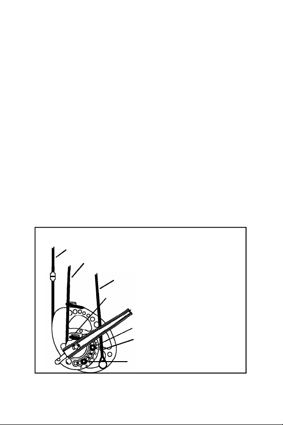
WHEEL & 1/2 OPTIONAL DRAW STOP
The draw stop on the Wheel & 1/2 system can be utilized to customize the feel of the back wall. If you
prefer a hard wall, install the peg in the threaded 632 hole in the bottom cam as shown in Figure 19. If
you prefer a softer wall and more of a "valley," shoot
the wheel without the draw stop installed. The use of
any non-Hoyt draw stop will void the product warranty and may damage the product.
VERSA CAM & 1/2 DRAW LENGTH ADJUSTMENT
Hoyt’s youth cam, the Versa Cam & 1/2 System, features a patented inner-cam draw length adjustment
that does not require the use of a bow press. To
adjust the draw length, start by removing the draw
length screw and the module fastening screw from
the bottom cam. Rotate the module until the draw
BOTTOM CAM SET AT 20” DRAW
Bowstring
Control Cable
Buss Cable
fig 21
26
Control Cable Peg
Draw Length Screw
Draw Length Indicator Arrow
Fastening Screw
(Lower Location)
23
Page 26
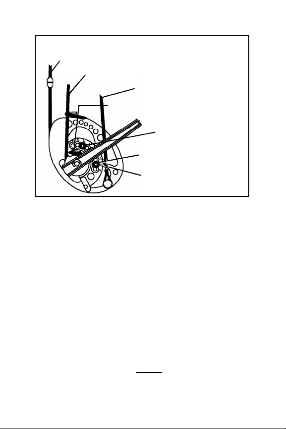
length indicator arrow on the cam aligns with the
desired draw length scribed on the module (Figure
21). Reinstall both screws and re-tighten. Note that
at draw lengths between 18 and 22 inches the lower
fastening screw location will be utilized (Figure 21),
while draw between 23 and 26 inches utilize the
upper module fastening screw location (Figure 22).
Always be sure to install and tighten both module
screws prior to drawing or shooting the bow to prevent damage to the product.
After the bottom cam draw length is adjusted, repeat
the procedure on the top wheel by loosening the fastening screw and removing the draw length screw.
Rotate the module to the SAME draw length position
as the bottom module and replace and tighten both
BOTTOM CAM SET AT 25” DRAW
fig 22
Bowstring
Control Cable
Buss Cable
Control Cable Peg
Fastening Screw
(Upper Location)
Draw Length Screw
Draw Length
Indicator Arrow
24
Page 27
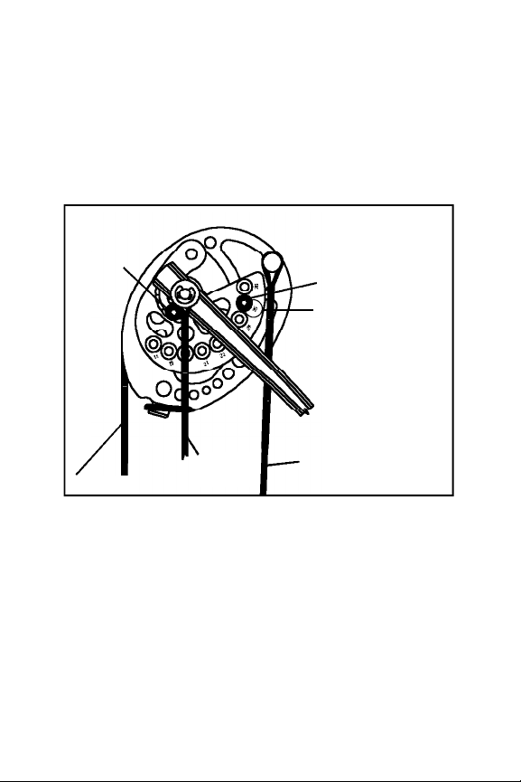
the draw length screw and the module fastening
screw. Note that the draw length of the top cam is
indicated by the number closest to the draw length
screw (Figure 23). Ensure both screws are installed
and tightened prior to drawing or shooting the bow
to prevent damaging the product.
VERSA CAM & 1/2 CONTROL CABLE REMOVAL
To remove the control cable from the bottom cam, the
bottom module must be rotated to a draw length of
20 inches or less. Failure to move the module prior to
installation or removal of the lower control cable
loop may result in damage to the string fibers and
premature cable failure.
fig 23
TOP
CAM
Draw Length Screw
Draw Length Setting
Module
Fastening
Screw
Bowstring
Control
Cable
Buss
Cable
25
Page 28
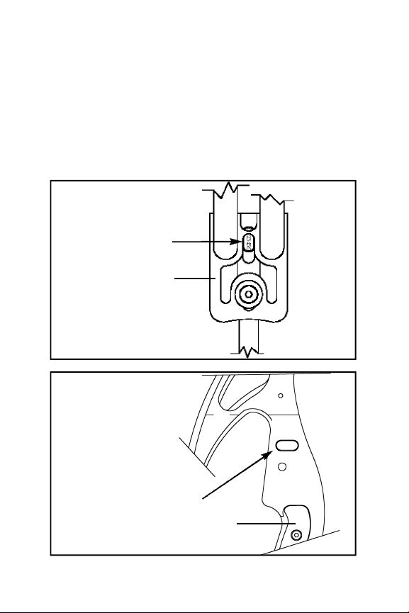
L O C ATING YOUR BOW’S SERIAL N U M B E R
The seven-digit serial number on all aluminum
Hoyt compound bows is located on the riser
between the top limbs and under the pocket. (See
fig 24) To find the serial number on magnesium
bows, look at the rest mount surface. (See fig 25) If
you have already attached a rest to your riser, you
may have to remove it to see the serial number.
0123456
fig 24
fig 25
Serial Number
Serial Number
ALUMINUM BOW
MAGNESIUM
BOW
Top Pocket
Grip
26
Page 29

TUNING YOUR BOW
T h e r e are numerous methods you can use when tuning
your Hoyt b o w. Hoyt recommends working closely
with your local pro shop when tuning your bow to
ensure best results. For detailed tuning information,
download Easton’s tuning guide at www.eastonarchery.com/downloads.
BROADHEADS
Most archers discover that they must make slight tuning adjustments when switching from practice points
to broadheads (even at the same weight). Broadheads
create a dramatic aerodynamic change in arrow flight.
For this reason, slight adjustments may need to be
made in nocking point height, rest position or bow
weight to achieve desired broadhead flight. Always
test shoot broadheads before hunting to ensure proper sight settings. Even expandable broadheads may
require different sight settings than field points.
HOYT COMPOUND BOW WARRANTY
All Hoyt compound bows are warranted against
defects in materials or workmanship to the original
o w n e r on all risers, limbs, limb pockets, and
eccentrics for the life of the product.
ACCESSORIES
All Hoyt sights (excluding sight pins), arrow rests,
and bow quivers (excluding hood foam and arrow
gripper) are warranted 100% for the life of the product
to the original owner. Hoyt must perform warranty
work.
27
Page 30

You must have the following items in order to obtain
warranty work:
1. A dated proof of purchase (sales receipt).
2. Products must be purchased through a Hoyt
authorized dealer (no exceptions!)
3. All compound bows must have a serial number.
(See page 26 for information on serial number location)
Buying a Hoyt bow over the Internet voids all
warranty.
Hoyt, at its discretion, voids all warranty claims either
expressed or implied including but not limited to evidence of abuse, modification to original design, use of
attachments or accessories that cause excessive stress.
Hoyt reserves the right to make substitutions on warranty coverage at Hoyt’s discretion for any reason.
Warranty is subject to available parts.
OBTAINING WARRANTY SERVICE
To obtain warranty service, you should return your
bow to the pro shop where you purchased your
Hoyt bow. The dealer can help to determine if Hoyt
factory service is required or if the repair can be completed by the pro shop. If the bow must be returned
to the factory, the bow owner is responsible for the
freight charges to Hoyt. Hoyt, in turn, will pay for the
same return freight of the repaired product.
28
Page 31

Before any bow is returned a Return Authorization
Number must be obtained through an authorized
Hoyt pro shop. Bows returned to the factory without
a Return Authorization number will be sent back. Do
not send accessories with bow unless otherwise
instructed to.
Write the RA number on the outside of the shipping
box and send the Hoyt bow requiring factory service
to:
Hoyt
543 N. Neil Armstrong Road
Salt Lake City, UT 84116
There are no other warranties expressed or implied
that extend beyond those written here. No agent,
employee or representative of Hoyt or its dealers has
the authority to bind Hoyt to any agreement not herein stated. Buyer agrees that the sole and exclusive
remedies for breach on any warranty concerning Hoyt
bows shall be repair or replacement of defective parts.
Hoyt shall not be liable for injury or property other
than the bows themselves. Hoyt reserves the right to
replace defective parts according to availability with
compatible replacement parts.
29
Page 32

543 North Neil Armstrong Road
Salt Lake City, Utah 84116-2887
(801) 363-2990 phone
(801) 537-1470 fax
www.hoyt.com
 Loading...