

Hoyt KW4000 User Manual
SERIES 4000
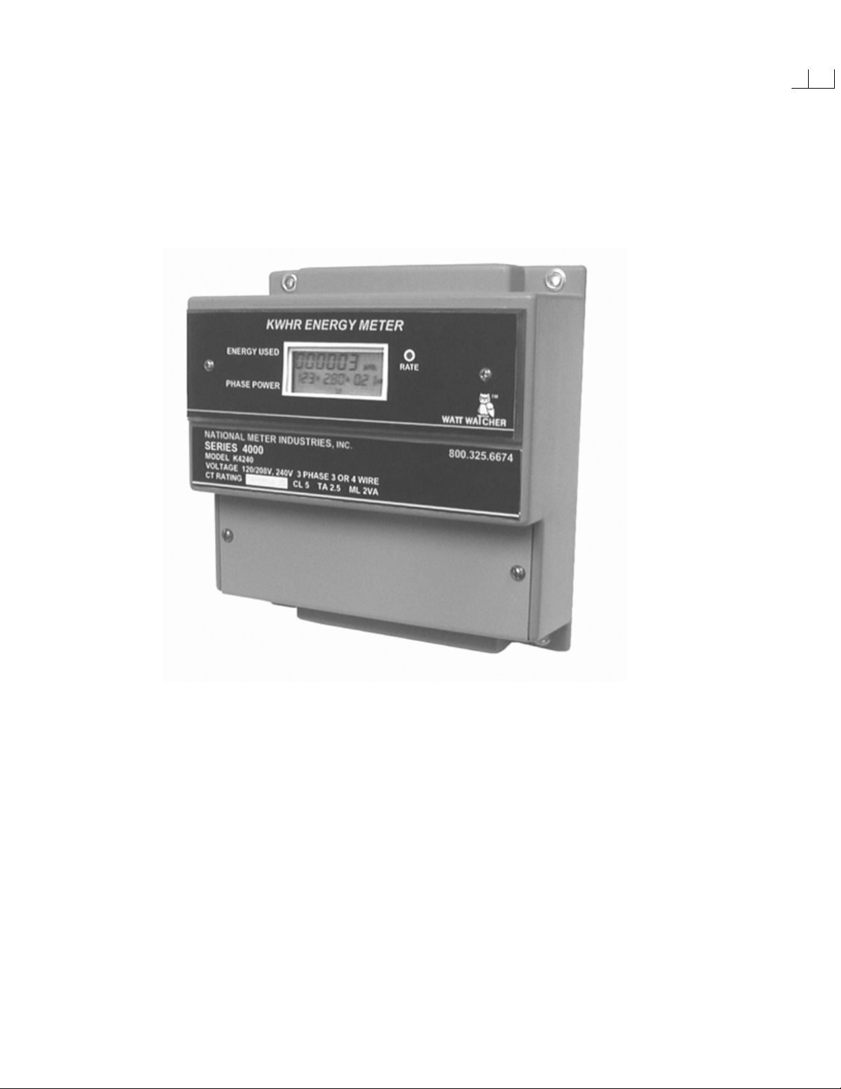
ENERGY METER
WATT WATCHER
INSTALLATION AND OPERATION MANUAL
HOYT ELECTRICAL INST. WORKS INC.
PENACOOK, NEW HAMPSHIRE PHONE 800-258-3652
www.hoytmeter.com

INDEX
Short Cut to Resetting the Demand Readings Inside Front Cover
Introduction 1.
. Main Features 2.
The Meter Terminal Description 3.
Wiring Diagrams 4.
Wiring Instructions 5.
Solid Core Current Transformers 5.
Split Core Model “TP” Current Transformers 6.
Split Core Model “1250” Current Sensors 7.
Common Terms Used in Metering 8.
Specifications 9.
Communications 10.
ModBus Protocol 11.
Trouble Shooting 12.
Warranty Back Cover

INTRODUCTION:
You now have in your possession one of the most reliable and highly accurate meters ever
manufactured.
To insure proper installation and performance please take the time to read this manual before
installing this meter. The installation information contained within this manual is to be used as a
guide and any applicable electrical codes must take precedence over the information contained
within.
**WARNING**
We recommend that all electrical circuits that you are working on be DE-ENERGIZED prior to
installation of this meter or current transformers. If this is not possible than any and all
applicable OSHA Safety Rules, Union Safety Rules or any other applicable safety rules when
working with energized circuits must be adhere to. A license electrician must perform this
installation for all applicable warrantees to be in effect.
The Series 4000 kit is made up of 4 components; 1 meter and 3 CTs. Solid core CTs up to 400
Amps are included in the standard kit, with larger sizes and split core CTs as an option. The line
wires feeding this meter shall be protected with in-line 5 Amp fuses or a 15-Amp 3-pole circuit
breaker. Most all of our current transformers have a 5 Amp at F.L. secondary output. Never
leave the black and white wires open when the meter is out of service. There is an
appreciable voltage depending on the rating of the CT and the primary load. An open CT will
hum and vibrate in larger sizes.
CHECK FOR SHIPPING DAMAGE and SHORTAGES
The Watt Watcher Meters are shipped in a protective box with the solid core CTs. Split Core
CTs may be in another box. After unpacking your meter please check for obvious damage or if
any components are missing. In either case promptly notify the distributor where it was
purchased.
ERRORS AND OMISSIONS:
We have taken all precautions to create a complete installation manual. NMI is not liable for any
omissions or errors contained within. Please contact us if you have any questions after reading
through this manual. Thank You.
NOTE TO THE ELECTRICIAN: PLEASE LEAVE THIS MANUAL WITH THE
METER WHEN LEAVING. THANK YOU!
1.

MAIN FEATURES:
The Series 4000 is factory programmed offering one model for both 3 or 4 wire services or
branch circuits. The factory has program the Amperage, and a 15-min. demand period (KW4000
only), according to the distributors purchase order.
There are six (6) kWh digits across the top section of the display, which are the kilowatt-hours
accumulated. There are no resets available for kWhs, like a utility meter and there are no
multipliers needed to read the energy consumed. There are three additional readings along the
bottom of the display. These readings are three digits of voltage, three digits of amperage and
three digits of instantaneous kilowatts. These power readings will display “HI” when the
readings go to 4 digits i.e., 1000 Amps or kW.
The Series 4000 Demand Meter (Model KW4000) will scroll to Maximum Demand (pd). The
demand interval is factory set at 15 minutes unless otherwise instructed. Sliding or Rolling
Window is the demand method used by this meter.
The factory programs the relay to1-KWhr per pulse, as a standard unless otherwise instructed.
There is a RS485 ModBus terminal next to the relay. This port works with our Intelligent
Converter that plugs into the RS232 Com Port in your computer. NMI offers software programs.
Call the factory for more information.
The voltage and the current terminals are removable. If a field calibration check is necessary the
terminals simply unplug and a portable meter tester can plug into them. These terminals are a
standard feature on all of our meters. Also the CTs have two extra terminals that are used when
paralleling two sets of CTs. Remember Current Sensors with voltage outputs cannot be
paralleled. Voltage is not additive in parallel, where current is.
There are holes in each corner of the meter for mounting the meter against a plywood board,
sheet rock wall or switch boards. We don’t recommend that the meters be mounted against a
concrete wall. If there are any technical questions that this manual does not cover please call our
technical desk at (603) 753-6321.
2.

THE SERIES 4000 CONNECTION TERMINALS
Terminal No. Designation Description
L1 – L2 Power Supply Power Supply at 230 or 480 VAC
Relay Pulse Reed Relay
RS 485 ModBus Protocol RS485 Daisy Chains to other meters
N N Neutral
L1 Measuring Voltage Voltage signal from Phase L1
L2 Measuring Voltage Voltage signal from Phase L2
L3 Measuring Voltage Voltage signal from Phase L3
CT1 B&W Current Transformer
CT2 B&W Current Transformer
CT3 B&W Current Transformer
Current or milli-volt signal from CT1
Current or milli-volt signal from CT2
Current or milli-volt signal from CT3
Note:
Color-code and size all wires according to National Electric Code.
Current Transformer wires shall be twisted to cancel noise.
Current Transformers and Line Voltage shall be phase related i.e., L1 and CT1 from the same
phase the same with L2 and L3.
3.
 Loading...