

Hoya AF-360FGZ User Manual
AUTO ZOOM ELECTRONIC
FLASH UNIT
OPERATING MANUAL
Please read this operating manual carefully first for proper use.

Thank you for purchasing the PENTAX Auto-flash AF360FGZ.
In addition to easy daylight sync photography with TTL auto, the AF360FGZ also allows wireless TTL auto (P-TTL
auto) photography and high-speed sync. It is a clip-on type flash which enables accurate focus adjustments even in
dark locations with built-in AF-assist spotbeam.
Bundled Items
The following items are supplied with this product.
Check that all the items have been included before use.
● Case
● Operating manual (this manual)
● Certification
PENTAX is a trademark of HOYA CORPORATION.

FOR THE SAFE USE OF YOUR FLASH UNIT
Although we have carefully produced this flash unit for safe operation, please be sure to especially follow warnings
and cautions given on page 2.
WARNING
This symbol indicates that violating this item could cause serious personal injuries.
CAUTION
This symbol indicates that violating this item could cause minor or medium personal injuries, or material losses.
is a symbol indicating items that are prohibited.
is a symbol emphasizing a warning.
1
WARNING
The flash contains electronic circuits that
operate at high voltages. Do not attempt to
disassemble the flash unit yourself, as there is
danger of an electric shock.
If internal parts of the flash unit becomes
exposed due to impact, etc., do not touch them
as there is danger of an electric shock.
Do not expose the flash unit to water or
moisture as there is danger of an electric
shock.
2
CAUTION
Do not use the flash near anyone’s eyes, as it
may hurt them. Be particularly careful with the
flash around infants.
The following may lead to an explosion or fire.
● Shorting the batteries
● Exposing the batteries to flames
● Dismantling the batteries
● Remove the sticker covering the battery.
● Attempting to recharge non-rechargeable
batteries
Remove the batteries from the camera
immediately if they become hot or begin to
smoke. Be careful not to burn yourself during
removal.

Precautions for Your Flash Unit
● Never use organic solvents such as paint thinner, alcohol or benzene to clean the flash unit.
● Avoid leaving the flash unit for extended period in places where the humidity and temperature are very high
such as in a car.
● Be careful not to subject the flash unit to strong vibrations, shock or pressure. Use a cushion to protect the flash
unit when carrying it in a motorcycle, car, boat, etc.
● Do not use the flash unit where it may be directly exposed to rain, water, etc.
● Replace all the batteries at the same time. Do not mix battery brands, type or an old battery with a new one. It
may cause explosion or overheating.
● When using the flash unit off the camera, do not try to attach any metallic object to the electric contacts or to
mount incompatible accessories. Otherwise, the TTL auto mechanism may be damaged or rendered
inoperable.
● Periodic checks are recommended every 1 to 2 years in order to maintain high performance. If the unit has not
been used for an extended period of time, or is being readied for an important shoot, it is recommended that
you take a test flash with the test button and test shoot with it. Test flash is also important to maintain optimum
performance.
● Avoid contact with garbage, dirt, sand, dust, water, toxic gases, salt, etc. When the flash unit is subjected to rain
or moisture, wipe it off with a dry soft.
● When photographing black subjects or white subjects, use exposure compensation.
● Do not attach any accessories having either fewer or different (layout other than PENTAX standard) electrical
contacts for the hot shoe or grip. Otherwise, some functions may not work properly.
● We will not be held responsible for any accidents or damage, etc. caused due to the use of this product with
cameras and accessories made by the other companies.
3

■ Cautions Regarding Batteries
● This flash unit uses four AA alkaline, lithium, or nickel metal hydride batteries. Do not use any other type of
batteries. The flash unit may not be able to operate correctly or demonstrate sufficient performance, or the flash
unit itself may generate heat, depending on the type of batteries used.
● AA alkaline and lithium batteries themselves are not rechargeable. Also, do not dismantle the batteries. Trying
to recharge or dismantle these batteries may cause an explosion or leakage.
● When changing batteries, do not mix batteries of different manufacturers, type and capacity.
● Do not insert the batteries with the positive (+) and negative (-) terminals the wrong way around. Incorrect
insertion may lead to an explosion or fire.
● Battery performance may temporarily be hindered in low temperatures. Batteries should be kept warm in
temperatures below freezing for proper performance.
● If you do not intend to use the flash unit for an extended period of time, remove the batteries. Leaving the
batteries in may cause damage to the flash unit due to leakage etc.
4

Contents
FOR THE SAFE USE OF YOUR FLASH
UNIT ................................................................. 1
Precautions for Your Flash Unit ....................... 3
Cautions Regarding Batteries............................. 4
Names of Parts ................................................... 6
LCD Panel Indicator............................................ 8
Inserting the Batteries ..................................... 10
Mounting to Camera......................................... 12
Turning the Power On...................................... 13
Auto Power Off Function................................... 14
Quick Power On Function................................. 14
Select Button (S)/Adjustment
Dial Functions............................................... 15
Camera Format and Flash
Coverage Angle ............................................ 17
Using the Flash Modes .................................... 22
P-TTL Auto Flash.............................................. 23
TTL Auto Flash ................................................. 24
Auto Flash......................................................... 25
Manual Flash .................................................... 27
Using the Sync Mode ....................................... 29
Leading Curtain Sync Mode ............................. 30
Trailing Curtain Sync Mode .............................. 30
High-Speed Sync Mode.................................... 31
Contrast Control Sync Flash............................. 33
Advanced Functions ........................................ 35
Wireless Mode .................................................. 35
Slave................................................................. 47
Slave Mode Setting........................................... 49
Slow-Speed Sync Photography........................ 50
Bounce Flash.................................................... 51
AF Spotbeam.................................................... 53
Wide-Angle Panel and Catchlight Panel ........... 54
Modeling Flash/Test Flash................................ 55
Connecting the AF360FGZ with the
Extension Cord ............................................. 56
Supported Functions for
PENTAX Cameras......................................... 57
Cameras that Support Each Flash Mode.......... 57
Cameras that Support Each Sync Mode .......... 59
Cameras that Support Wireless Mode.............. 60
Cameras that Support Slow-Speed Sync
Mode............................................................. 61
Functions Related to Each Flash Mode............ 61
Sync Mode Restrictions.................................... 69
Precautions When Photographing with a
Slave Flash................................................... 76
Flash Effective Range ...................................... 77
Calculating the Flash Effective Range.............. 77
Guide Number (GN).......................................... 79
P-TTL and TTL Auto Flash Effective Range ..... 82
Optional Accessories....................................... 84
Specifications ................................................... 85
Warranty Policy ................................................ 91
5

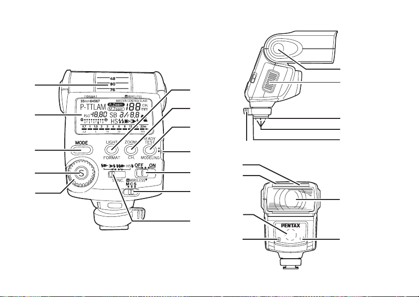
Names of Parts
Bounce angle adjustment
LCD panel
Flash mode button
Select button
Adjustment dial
LCD panel illumination button/ Format button
Zoom button/ Channel button
Test button/ Modeling button/ Ready lamp
Setting switch
Power switch
Wireless mode switch
@ Sync mode switch
6
> Bounce lock release button
S Battery chamber cover
Y Shoe lock pin
G Flash signal contacts
T Shoe foot
V Locking lever
[ Wide-angle panel
W Catchlight panel
K AF spotbeam emitter
Q Auto flash sensor
R Flash head
" Wireless sensor
>
S
@
[
W
K
Q
V
Y (Inner pin)
G
T
R
"
7
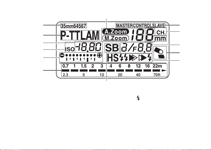
■ LCD Panel Indicator
Zoom indicator : A.Zoom ➝ M.Zoom xxmm = 20, 24, 28, 35, 50, 70, 85 (35 mm format)
Format indicator : 35mm ➝ 645 ➝ 67
Flash mode indicator : P-TTL ➝ A ➝ M ➝ SB
Flash exposure
compensation indicator
ISO indicator : ISO 25 to 1600
Bar graph
Effective flash range
indicator
AF spotbeam : SB
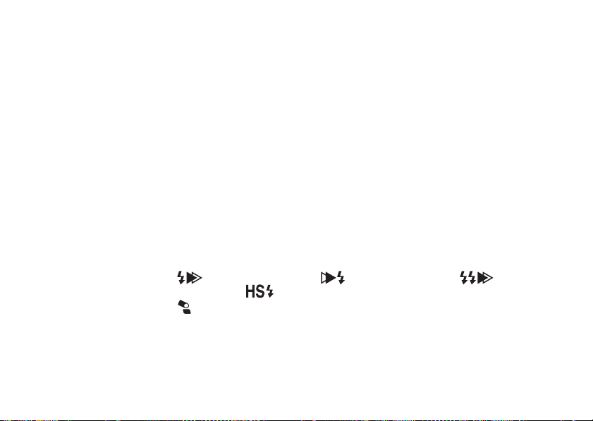
Sync mode indicator : (Leading curtain sync) - (Trailing curtain sync) - (Contrast
Bounce flash warning :
Flash output adjustment
indicator
f/stop : F2 to F22 (When set to ISO 100)
@ Channel indicator : 1 to 4CH
>
Wireless mode indicator
: -3.0 to +1.0 steps, 0.5 step increments
: Minimum distance - Maximum distance (in P-TTL, TTL, A modes)
Minimum distance (in manual mode)
control sync) - (High-speed sync)
: NN/ X X
: MASTER, CONTROL, SLAVE
8
35, 45, 55, 70, 100, 135, 150 (645 format)
55, 60, 70, 90, 120, 180, 190 (67 format)
13, 16, 19, 24, 34, 48, 58 (Digital camera (K series,
*ist D series))
25, 30, 35, 43, 62, 87, 106 (645D)
>
@
When in poorly lit locations and the LCD panel cannot
be seen, pressing the LCD panel illumination button
(LIGHT) will illuminate the panel for about 10 seconds.
Pressing it again will turn off the illumination.
● The camera's LCD panel lights up also when you
press the LCD illumination button (LIGHT) and
the exposure metering timer is on for the
following camera.
MZ-S
Auto Check Display
If the correct flash output is obtained, the flash mode
indicator and () in the viewfinder will begin blinking.
If the auto check display does not blink, the flash output
is insufficient. Verify the effective flash range (refer to
page 77) and adjust the distance to the subject, or open
the aperture further.
Even if the auto check display is blinking, the flash
output may be incorrect if the subject is too close.
● Depending on the combination of flash mode
and camera, the auto check display may not
display correctly
9
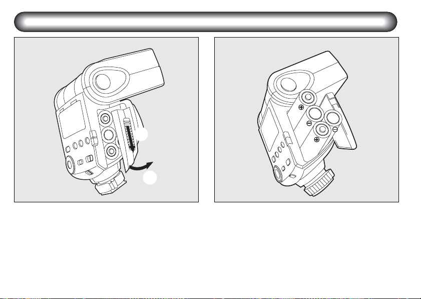
Inserting the Batteries
Slide the battery chamber cover as shown in the
1 2
figure to open.
10
Insert four AA batteries, making sure the plus/
minus markings (+, -) match the diagram
inside the battery chamber cover.

Types of Batteries
This flash unit uses four AA batteries of the same type,
as shown below.
- Alkaline battery (LR6)
- Lithium battery (FR6)
- Nickel-Metal Hydride battery (Ni-MH)
(Nickel manganese (Ni-Mn) and nickel cadmium (NiCd) batteries cannot be used.)
● For information about recycling times and total
number of flashes, refer to “Specifications” on
page 85.
● If the indicators on the LCD panel or the ready
lamp does not light up, the batteries may be
exhausted or not inserted correctly. Verify the
orientation of the batteries or, if the indicators
and ready lamp still do not light up, replace them
with new batteries.
● If you let the flash unit discharge successively
using lithium batteries, the batteries will
overheat, activating a safety circuit that
temporarily disables the flash unit. If this occurs,
rest the flash unit so that the temperature of the
batteries returns to normal.
11
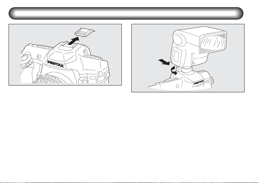
Mounting to Camera
1
Remove the hot shoe cover from the camera.
1
Attach the flash unit to the camera.
2
Turn the locking lever of the flash unit in the
direction opposite to that indicated by (FIX➝)
(clockwise from the direction of the LCD
panel).
Slide the hot shoe foot of the flash unit into the
camera's hot shoe from the back of the
camera forward.
Turn the locking lever of the flash unit in the
direction indicated by (FIX➝) to lock it.
12
2
●
The following cameras have a shoe lock pin. When
attaching the flash unit, turn the locking lever in
the (FIX➝) direction and lock the flash unit to the
camera with the shoe lock pin. When releasing the
flash unit, be sure to do so after turning the
locking lever in the direction opposite to that
indicated by (FIX➝) and loosening the shoe lock
pin. Otherwise, the hot shoe will be damaged.
645D, K-x, K-7, K-m/K2000, K20D, K10D, K200D,
K110D, K100D Super, K100D, *ist D series,
*ist, MZ-S, MZ-L/ZX-L/MZ-6, MZ-60/ZX-60
● The 672 does not come with a hot shoe. The
optional hot shoe grip 672 should be used.
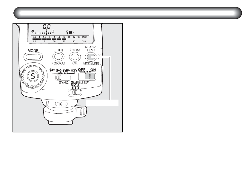
Turning the Power On
œŦŢťźġŭŢŮű
Sliding the power switch to the (ON) position will turn
on the power. The ready lamp will light up when the
flash is charged. Sliding it to the (OFF) position will turn
off the power.
If charging time takes more than 20 seconds, the
batteries are exhausted and should be replaced with
new batteries. If the flash unit is used with exhausted
batteries, the settings may return to their default
configuration.
● Turn the camera on before turning the flash unit
on.
● The WIRELESS position of the power switch is
used for wireless mode and slave flash lighting.
For details, see the explanations for each
function.
➝
Wireless mode (page 35 - 46)
➝
Slave flash (page 47 - 48)
13

■ Auto Power Off Function
When the flash unit is left unused for about 3 minutes
with the power switch set to the (ON) position, it
automatically turns off to save the power.
● In the auto flash mode (A), the power will turn off
after about 6 minutes.
● In the wireless mode, the power will turn off after
about 1 hour of non-operation.
■ Quick Power On Function
If the flash unit is mounted on autofocus cameras,
press the shutter release button half way to turn on the
power.
14
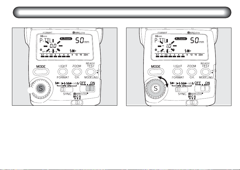
Select Button (S)/Adjustment Dial Functions
4 types of settings are available as shown on the following pages for the select button (S) and the adjustment dial.
Procedure
Press the select button (S) so that the number to
1
adjust blinks.
Turn the adjustment dial and adjust the blinking
2
number.
15

After adjustment, press the select button (S) and
3
stop the blinking. Adjust the other items below
using the same procedure.
● When using multiple flash units set to P-TTL or
TTL Auto and adjusting the amount of light at the
same time, use the camera’s exposure
compensation.
Connected Flash Mode Adjustment Range
Flash exposure compensation P-TTL Auto flash -3.0 to +1.0 levels (EV) (0.5 step increments)
ISO / F (aperture) setting Auto flash (A) ISO 25 to ISO 1600, F2 to F22 (with ISO100)
Manual flash output Manual (M) 1/1, 1/2, 1/4, 1/8, 1/16, 1/32
Flash output setting
16
Wireless (W) master flash (M)
Wireless (W) slave flash (S)
1/1, 2/3, 1/2, 1/3
Camera Format and Flash Coverage Angle
The AF360FGZ’s flash coverage angle can be adjusted
to match the angle of view of the lens being used,
which enables effective distribution of the flash light.
The flash coverage angle is indicated by the focal
lengths of available lenses in the LCD panel of the flash
unit, according to the preset image size (FORMAT) of
the camera.
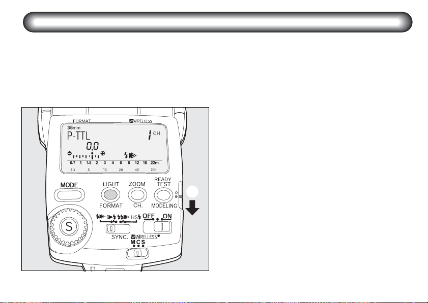
1
Format setting
Firstly, set the FORMAT to match the image size
of the camera you are using.
The format size will automatically be set when
the shutter release button is pressed halfway
down when the AF360FGZ is used in
combination with the following cameras.
645D, K-x, K-7, K-m/K2000, K20D, K200D,
K100D Super, K10D, K110D, K100D, *ist DL2,
*ist DS2, *ist DL, *ist DS, *ist D, *ist,
MZ-L/ZX-L/MZ-6, MZ-S
For other cameras, before use, set the FORMAT
to match the image size of the camera according
to the following procedure.
Slide the setting switch down (yellow dot).
Press the FORMAT button repeatedly to
display camera formats (image sizes) in the
LCD panel.
You can switch from 35mm ➝ 645 ➝ 67 ➝
35mm in that order.
17
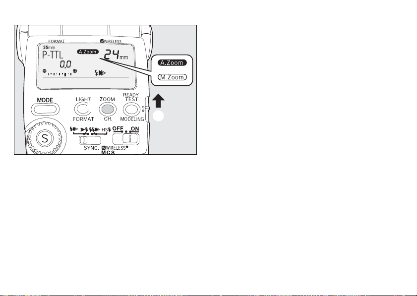
Zoom position (Flash coverage angle) setting
2
Next, set the zoom (flash coverage angle) to
match the focal length of the lens you are using.
Auto Zoom (A.Zoom)
If both the camera and lens are autofocus, you can
automatically set the flash coverage angle according to
the focal length of the lens by pressing the shutter
release button of the camera halfway down.
The auto zoom function operates while the
exposure meter is operating (while information is
being displayed in the viewfinder).
18
If you are setting the format manually, return
the setting switch to the upper (white dot)
position.
When (M.Zoom) is displayed on the LCD
panel, press the zoom button (ZOOM)
repeatedly until (A.Zoom) is displayed.
● When the flash mode is set to auto flash, the
auto zoom function does not operate even if the
camera and lens are both autofocus. Set the
zoom manually to match the lens angle of view.
Manual Zoom (M.Zoom)
If one or both of the camera and lens are manual
focus, you must set the flash coverage angle
manually.
If you are setting the format manually, return
the setting switch to the upper (white dot)
position.
Press the zoom button (ZOOM) until the focal
length of the lens being used is displayed on
the LCD panel or if it can not be displayed
exactly one wider than the lens focal length.
The zoom position is switched in the order
shown in the diagram on page 20.

Zoom Positions by Camera format
* With the wide-angle panel
35mm camera 645 camera 67 camera Digital camera
(K series, *ist D series)
20mm* 35mm* 55mm* 13mm* 25mm*
24mm 45mm 60mm 16mm 30mm
28mm 55mm 70mm 19mm 35mm
35mm 70mm 90mm 24mm 43mm
50mm 100mm 120mm 34mm 62mm
70mm 135mm 180mm 48mm 87mm
85mm 150mm 190mm 58mm 106mm
● When the wide-angle panel is used, the zoom
button (ZOOM) will not work. (The wide-angle
panel is in a slit on the top of the flash head. Pull
it out so that it covers the front of the flash head.
If the catchlight panel is not necessary, leave it in
the slit.)
Digital camera
(645D)
19
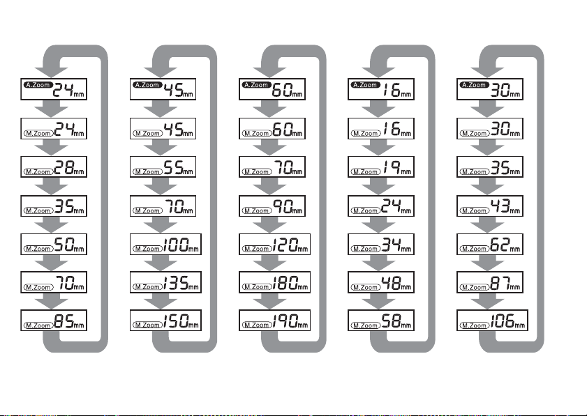
35mm Camera 645 Camera 67 Camera
20
Digital Camera
(K series, *ist D)
Digital Camera
(645D)

● In the (A.Zoom) mode, the flash coverage angle
will be adjusted automatically to suit the lens
focal length when you press the shutter release
button halfway, and the camera exposure
metering timer is on.
● A warning signal appears as follows when the
flash cannot cover the focal length of the
camera.
- The zoom indicator blinks for the combination of
the following camera and lenses.
Camera Lens Types
*ist D series DA, D FA, FA J, FA, F
35mm autofocus single
lens reflex cameras
645N2, 645N FA645
- The warning signal does not appear for the
combination of the following cameras and focal
lengths.
D FA, FA J, FA, F
Camera Focal length
*ist, MZ-L/ZX-L/MZ-6,
MZ-S
*ist DL, *ist DS, *ist D
20 mm and over, less
than 24 mm
13 mm and over, less
than 16 mm
● In the (A.Zoom) mode, if there is no lens focal
length information, the flash coverage angle will
be set automatically to 24mm with a 35mm
camera. With a 645 camera, it will be set to
45mm, with a 67 camera it will be 60mm, with a
digital camera (K series, *ist D series) it will be
16mm, and with a digital camera (645D) it will be
30mm.
● When using the wide-angle panel, the angle will
be fixed at 20 mm for a 35 mm camera, 35 mm for
a 645 camera, 55 mm for a 67 camera, and 13 mm
for a digital camera (K series, *ist D series),
25mm for a digital camera (645D) in both A.Zoom
and M.Zoom.
21

Using the Flash Modes
The AF360FGZ has the following flash modes. Select
the mode best suited for the subject.
Before photographing, confirm the following.
1. Whether your camera supports the desired flash
mode.
➝ Cameras that Support Each Flash Mode
(page 57)
2. Whether you can use the desired function with
the combination of your camera and the flash
mode you have set.
➝ Functions Related to Each Flash Mode
(page 61 - 68)
P-TTL auto flash (P-TTL)
A pre-flash is discharged before the main flash so that
the multi-segment metering sensor can measure the
subject's distance, brightness, brightness difference,
backlit condition, etc. The data obtained is incorporated
to set the output of the main flash. This mode obtains
more accurate results than with the conventional TTL
mode. Refer to page 23 for instructions on how to use
this flash mode.
22
TTL auto flash (TTL)
Based on the amount of light reflected off the film of the
camera, the camera adjusts the flash output
automatically to obtain a correct exposure. Refer to
page 24 for instructions on how to use this flash mode.
Auto flash (A)
The built-in flash metering sensor adjusts the flash
output automatically. Use with cameras that are not PTTL or TTL Auto flash compatible. Refer to page 25 for
instructions on how to use this flash mode.
Manual flash (M)
When the camera is set to manual exposure, manual
flash can be set to suit the subject distance and
aperture. The manual flash output can be set to 1/1,
1/2, 1/4, 1/8, 1/16, or 1/32. Refer to page 27 for
instructions on how to use this flash mode.
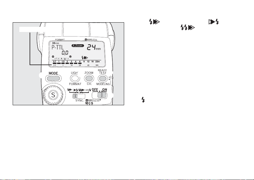
■ P-TTL Auto Flash
EffectiveFlash range
Refer to page 22 for the features and conditions of use
of this flash mode.
Procedure
Turn on the flash unit.
1
Press the flash mode button (MODE) until
2
(P-TTL) is displayed on the LCD panel.
Set the sync mode switch to leading curtain sync
3
( ), trailing curtain sync ( ), or
contrast-control ( ), according to the
subject. (Refer to page 29.)
● After turning the power (ON), the setting will be
(P-TTL) and (A.Zoom).
Set the zoom position. (The setting method
4
differs according to your camera and lens. Refer
to page 18.)
Confirm that the subject is within the effective
5
flash range and the ready lamp is lit. Then take a
picture.
● In the following cameras, if the correct flash
output is obtained, the flash mode indicator and
( ) in the viewfinder will blink.
*ist, MZ-S, MZ-L/ZX-L/MZ-6
For details, refer to “Auto Check Display” on
page 9.
● The correct flash output is obtained in P-TTL
auto mode only when the flash unit is used with
autofocus lenses.
● If necessary, an exposure compensation amount
can be set between +1.0 to -3.0 steps in 0.5-step
increments. (Refer to page 15.)
23
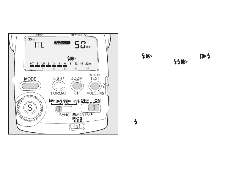
■ TTL Auto Flash
Refer to page 22 for the features and conditions of use
of this flash mode.
24
Procedure
Turn on the flash unit.
1
Press the flash mode button (MODE) until (TTL)
2
is displayed on the LCD panel.
Set the sync mode switch to leading curtain sync
3
( ), trailing curtain sync ( ), or
contrast-control ( ), according to the
subject. (Refer to page 29.)
Set the zoom position. (The setting method
4
differs according to your camera and lens. Refer
to page 18.)
Confirm that the subject is within the effective
5
flash range and the ready lamp is lit. Then take a
picture.
● In the following cameras, if the correct flash
output is obtained, the flash mode indicator and
( ) in the viewfinder will blink.
35 mm single lens reflex cameras
SF10, 672, 645N2, 645N, 645, LX, Super A/
Super Program
For details, refer to “Auto Check Display” on
page 9.
except for SF7/
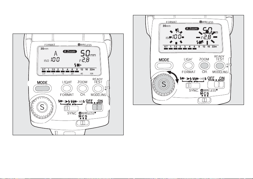
■ Auto Flash
Refer to page 22 for the features and conditions of use
of this flash mode.
25

Procedure
Turn on the power switch.
1
Press the flash mode button (MODE) until (A) is
2
displayed on the LCD panel.
Set the aperture value and ISO.
3
Press the select button (S) so that (f/stop) on
the LCD panel blinks.
Turn the adjustment dial to set the aperture
value.
● The effective flash range is displayed on the LCD
panel bar graph.
Confirm that the subject is within the effective
flash range and press the select button (S).
Turn the adjustment dial to set the ISO after
(ISO) starts blinking.
Press the select button (S). The setting is
complete if (ISO) stops blinking.
Set the lens aperture to the same aperture value
4
as that set on the LCD panel.
● The camera's aperture value is synchronized
with that of the flash unit when the camera
exposure mode is set to Programmed AE or
Shutter Priority AE.
26
Set the zoom position. (The setting method
5
differs according to your camera and lens. Refer
to page 18.)
● Select (M.Zoom) regardless of the type of lens
being used.
Confirm that the subject is within the effective
6
flash range and the ready lamp is lit. Then take a
picture.
● In the following cameras, if the correct flash
output is obtained, the flash mode indicator and
( ) in the viewfinder will blink.
645, LX, Super A/Super Program, MZ-M/ZX-M,
P30T, P30N/P3N, P30/P3, P50/P5, A3Date,
A3DateS, Program A/Program Plus
For details, refer to “Auto Check Display” on
page 9.
● If the power is turned temporarily OFF, the flash
will be set to P-TTL or TTL auto. Return the
setting to Auto flash.
● The sync mode will be fixed in leading curtain
sync.

■ Manual Flash
Refer to page 22 for the features and conditions of use
of this flash mode.
Procedure
Turn on the power switch.
1
Press the flash mode button (MODE) to display
2
(M) (1/xx) on the LCD panel.
● You can set the flash output from 1/1 to 1/32. See
page 15.
Set the zoom position. (The setting method
3
differs according to your camera and lens. Refer
to page 18.)
Set the lens aperture according to the distance to
4
the subject.
Example:
If the flash zoom position is 35mm, subject distance
(between the AF360FGZ and subject) is 3 m, and
sensitivity is ISO 100, the calculation will be as
follows:
With flash output (1/1), the Guide No. will be 25
(according to the Guide No. table).
Aperture = Guide No. 25 / Subject distance 3 m =
8.3 Approx. 8 (f/Stop)
● Refer to page 79 for the guide number table.
27
 Loading...