

Page 1
®
OXYGEN
ANALYZER
MODEL
OM-25A
USER’S GUIDE
AND
OPERATING
INSTRUCTIONS
R213M15 Rev. K
manufactured by:
Page 2

Manufacturer: Maxtec, Inc
European Representative
Airox S.A.
Parcd’activities Pau-Pyrenees
L’echangeur BP833
64008 PAU Cedex
France
Page 3

PREFACE
This manual describes the function, operation and maintenance of the
Maxtec Model OM-25A hand-held oxygen analyzer. A member of
Maxtec's MAXO
2 analyzer line of oxygen analyzers and monitors, the
OM-25A utilizes the MAX-250 oxygen sensor and is engineered for fast
response, maximum reliability and stable performance. The OM-25A is
designed primarily for spot-checking oxygen concentration delivered by
oxygen concentrator units, however, its internal sensor and adaptable
sampling port make it suitable for a wide variety of oxygen analysis
applications.
THANK YOU
Thank you for your purchase of a Maxtec MAXO2 oxygen analyzer. We
appreciate the time and energy you invest in selecting the equipment best
suited to your needs. As repayment, we are supplying you with a reliable,
high-quality instrument that, with proper care and operation, will provide
you with years of exceptional service. We also encourage your
comments or suggestions as to how our equipment, in any way, can
better serve your needs. Please feel free to write, FAX or e-mail us at the
address on the back of this manual c/o the Maxtec Marketing Department.
NOTE: In order to obtain optimum performance from your MAXO
analyzer, all operation and maintenance must be performed in
accordance with this manual. Please read the manual thoroughly
before using the analyzer and do not attempt any repair or
procedure that is not described herein. Maxtec cannot warrant any
damage resulting from misuse, unauthorized repair or improper
maintenance of the instrument.
2
WARNING
The sensor of the MAXO
with various anesthesia gases including Nitrous oxide, Halothane,
Isoflurane, Enflurane, Sevoflurane and Desflurane and found to have
acceptable low interferance, the device in its entirety (including
electronics) is not suitable for use in the presense of a flammable
anesthetic mixture. Only the threaded sensor face and sample inlet
connection may be allowed to contact such a gas mixture.
2 Oxygen Analyzer (MAXO2) has been tested
i
Page 4

To avoid explosion, do not operate the oxygen analyzer in the presence
of flammable anesthetics or in an atmosphere of explosive gases.
Operating the oxygen analyzer in flammable or explosive atmospheres
may result in fire or explosion.
Never allow an excess length tubing near the patient’s head or neck, as
such could result in strangulation.
Before use, all individuals who will be using the MAXO
2 must become
thoroughly familiar with the information contained in this Operation
Manual. Strict adherance to the operating instructions is necessary for
safe effective product performance. This product will perform only as
designed if installed and operated in accordance with the manufacturer’s
operating instructions.
Use only genuine Maxtec accessories and replacement parts. Failure to
do so may seriously impair the analyzer’s performance. Repair or
2
alteration of the MAXO
beyond the scope of the maintenance
instructions or by anyone other than an authorized Maxtec service person
could cause the product to fail to perform as designed.
Calibrate the MAXO
2 weekly when in operation and if enviromental
conditions change significantly. (ie, Temperature, Humidity, Barometric
Pressure. --- Refer to Calibration section of this manual).
Use of the MAXO
2 near devices that generate electrical fields may cause
erratic readings.
If the MAXO
2 is ever exposed to liquids (from spills or immersion) or to
any other physical abuse, turn the instrument OFF and then ON. This will
allow the unit to go through its self test and make sure everything is
operating correctly.
Never autoclave, immerse or expose the MAXO
o
high temperatures (>70
C). Never expose the device to pressure,
2 (including sensor) to
irradiation vacuum, steam, or chemicals.
To protect the unit from potential leaky battery damage always remove
batteries when the unit is going to be stored (not in use for 1 month) and
replace dead batteries with recognized name brand AAAlkaline batteries.
ii
Page 5

Classification:
Protection against electric shock: Internally powered equipment.
Protection against water: Ordinary equipment
Mode of Operation: Continuous
Sterilization: See section 6
Safety of application in the presensence of a flammable anesthetic
mixture: See section 8.1
FAILURE TO COMPLY WITH THESE WARNINGS AND CAUTIONS
COULD RESULT IN INSTRUMENT DAMAGE AND POSSIBLY
JEOPARDIZE THE WELL BEING OF THE PATIENT AND/OR HEALTH
CARE PROFESSIONAL.
iii
Page 6

TABLE OF CONTENTS
1. SYSTEM OVERVIEW ............................................. 1
1.1 Base Unit Description ................................ 1
1.2 Components Description ......................... 2
1.3 MAX-250 Oxygen Sensor ............................. 4
2. SET-UP PROCEDURE ......................................... 5
2.1 Battery Installation ..................................... 5
2.2 Calibrating The MAXO
Analyzer ........... 5
2
2.2.1 Before You Begin ........................... 5
2.2.2 To Calibrate The MAXO
2
Analyzer 6
2.2.3 Automatic Calibration To Room Air. 7
2.2.4 Factors Influencing Calibration ..... 8
3. OPERATION INSTRUCTIONS .............................. 9
4. SENSOR REMOVAL AND REPLACEMENT ......... 9
5. PROBLEM SOLVING ............................................... 11
6. CLEANING AND MAINTENANCE ......................... 11
7. SPECIFICATIONS ................................................ 12
7.1 Base Unit Specifications ......................... 12
7.2 Sensor Specifications .............................. 12
8. APPLICATIONS .................................................. 13
8.1 Exposure to Anesthetic Gases ............... 13
8.2 Calibration Techniques in Pressurized
Systems .................................................... 13
8.3 Calibration Errors .................................... 14
8.4 Atmospheres of High Humidity ............... 14
9. SPARE PARTS AND ACCESSORIES ................. 15
10.WARRANTY ......................................................... 16
iv
Page 7

1. SYSTEM OVERVIEW
1.1 Base Unit Description
The MAXO2 analyzer (Model OM-25A) provides unparalleled
performance and reliability, due to an advanced design that includes the
following features and operational benefits.
• Fast-responding, oxygen-specific, galvanic sensor that achieves
90% of final value in approximately 15 seconds at room temperature.
• Extra-life oxygen sensor of approximately 900,000 O
2 percent hours
(minimum 2 years in most normal applications).
• Adaptable sample input connection and internal sensor.
• Operation using only 2 AAalkaline batteries (2 X 1.5 Volts) for
approximately 3000 hours of performance in typical usage. For extra
extended long life, 2 AAlithium batteries may be used.
• Durable, compact case that permits comfortable, hand-held operation.
1
/
• Large, easy-to-read, 3
2-digit LCD display for readings in the 0-100%
range.
• Simple operation and calibration using quick-calibrate key functions.
• Self-diagnostic check of analog and microprocessor circuitry.
• Low battery indication.
1
Page 8

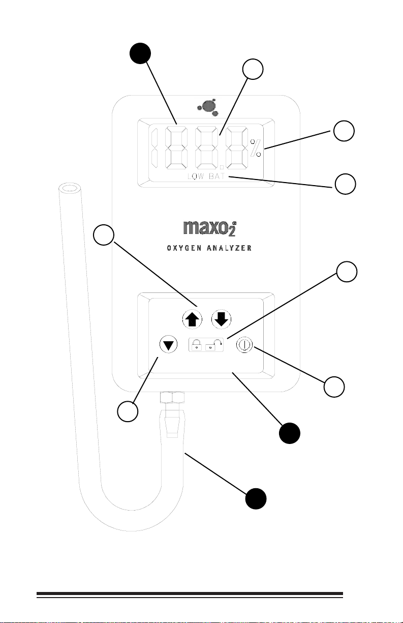
1.2 Components Description (please refer to page 3)
CD Readout
A
3 1/2-Digit Display- The 3 1/2-digit liquid crystal display (LCD)
1
provides direct readout of oxygen concentrations in the range of
0-100%. It also displays "CAL" when the calibration mode is
entered.
"%" Sign- The "%" sign is present during normal operation
2
when the keypad settings are locked. When the keypad settings
are unlocked, the "%" sign is not visible. In the calibration mode,
the "%" sign flashes every second.
Low Battery Indicator- The low battery indicator appears on
3
the LCD display when the power supply voltage drops below
acceptable limits. When the "LOW BAT" icon is visible, batteries
should be replaced immediately.
ad
Keyp
B
4
5
6
ON/OFF Key- (after Calibration) This key is used to turn
the instrument on or off. When batteries are installed in
the unit and the unit is in the power off mode, the display
will be blank. When the ON/OFF key is pressed once, the unit will
start to display the oxygen concentration and the keypad is
activated. If the ON/OFF key is pressed again, the unit reverts to
the power off mode.
LOCK/UNLOCK Key- The presence of the "%" sign on the LCD
readout is an indication that the unit is in its normal
"LOCKED" state. The unit must be unlocked in order to
be calibrated. Pressing the LOCK key will unlock the keypad and
cause the "%" sign to disappear. The unit can then be calibrated
if desired. If no other keys are pressed within 10 seconds, the
"%" sign will reappear and the unit will revert to the "LOCKED"
mode.
CALIBRATE Key- The Unit will force you to Calibrate the
first time power is applied or the sensor is changed. This is
indicated on the LCD by the word “CAL”. Pressing the
CALIBRATE key will allow the ↑ and ↓ arrow keys to calibrate the
unit. Also when the keypad is unlocked, the CALIBRATE key is
used in conjunction with the ↑ and ↓ arrow keys to calibrate the
unit. When the CALIBRATE key is pressed, "CAL" appears on
the LCD readout for 1 second and then the measured calibration
concentration is displayed. The calibration value can then be
2
Page 9
LCD Readout
7
A
1
2
3
5
4
6
Keypad
B
Sample Inlet
C
Connection
OM-25A
3
Page 10

changed using the ↑ and ↓ arrow keys. During calibration, the
"%" sign will flash at a once per second rate. When the
calibration value is set, pressing the CALIBRATE or
LOCK/UNLOCK key will cause the unit to exit the calibration
mode and return to normal operation. The unit will also revert to
normal operation if 10 seconds elapse and no keys are pressed.
↑↑
7
conjunction with the CALIBRATE key to calibrate the
unit. Pressing the ↑ or ↓ key will raise or lower the displayed
oxygen value in .1% increments. When either of these keys are
held down for more than 1 second, the display will scroll at a rate
of .4% per second.
C
Sample Inlet Connection
↓↓
and
Keys- The ↑ and ↓ arrow keys are used in
1.3 MAX-250 Oxygen Sensor
MAX-250 oxygen sensors offer quick response, stability and extra life on
the order of 900,000 percent oxygen hours.
The MAX-250 is a galvanic, partial pressure sensor that is specific to
oxygen. It consists of two electrodes (a cathode and an anode), a teflon
membrane and an electrolyte. Oxygen diffuses through the teflon
membrane and immediately reacts at a gold cathode. Concurrently,
oxidation occurs electrochemically at the lead anode, generating an
electrical current and providing a voltage output. Electrodes are immersed
in a unique gelled weak acid electrolyte which is responsible for the
sensors long life and motion insensitive characteristic. Since the sensor is
specific to oxygen, the current generated is proportional to the amount of
oxygen present in the sample gas. When no oxygen is present, there is
no electrochemical reaction and therefore, negligible current is produced.
In this sense, the sensor is self-zeroing.
CAUTION: The Maxtec MAX-250 oxygen sensor is a sealed
device containing a mild acid electrolyte, lead (Pb), and lead
acetate. Lead and lead acetate are hazardous waste
constituents and should be disposed of properly, or
returned to Maxtec for proper disposal or recovery.
CAUTION: Do not use ethylene oxide sterilization. Do not
immerse the sensor in any cleaning solution, autoclave or
expose the sensor to high temperatures.
CAUTION: Dropping or severely jarring the sensor after
calibration may shift the calibration point enough to require
recalibration.
4
Page 11

2. SET-UP PROCEDURE
2.1 Battery Installation
All MAXO2 analyzer units are powered by two, AA alkaline batteries (2 x
1.5 Volts) and are shipped without the batteries installed. The battery
compartment is accessible from the back side of the unit. To install the
batteries:
1) With the thumb, press down on the center of the battery compartment
cover and slide the cover off of the instrument case.
2) Install the two, AA, alkaline batteries (2 x 1.5 Volts) in the unit,
observing the orientation shown on the label inside the compartment.
3) Slide the battery compartment cover back onto the case. Make sure
the tabs on the cover snap into position, securing the cover flush
against the case.
When batteries are installed in the MAXO
self-diagnostic test. All segments of the LCD readout are turned on for
approximately 2 seconds. When the diagnostic test is completed
successfully, the word "OFF" will appear on the display, indicating that the
unit is ready to be calibrated.
analyzer, the unit initiates a
2
2.2 Calibrating the MAXO2Analyzer
2.2.1 Before You Begin
The MAXO2 Oxygen Analyzer should be calibrated upon receipt.
Thereafter, Maxtec recommends calibration on a weekly basis. However,
more frequent calibration will not adversely affect product performance.
More frequent calibration is required when:
• The temperature of the gas stream changes by more than 3 degrees
Celsius.
• Changes in elevation result in calibration error of approximately 1% of
reading per 250 feet. In general calibration of the instrument should
be performed when the geographic elevation at which the product is
being used changes by more than 500 feet.
In addition, calibration is recommended if the user is unsure when the last
calibration procedure was performed or if the measurement value
displayed is in question.
5
Page 12

It is best to calibrate the MAXO2 analyzer to a known documented
oxygen concentration at a pressure and flow similar to your clinical
application. Calibrating the MAXO
analyzer at lower concentrations with
2
a known oxygen value is also acceptable and may provide additional
accuracy if the calibration gas is closer to the environment in which the
MAXO
2 analyzer will be used. A “known” value of oxygen is defined as
an oxygen source which has a traceable certificate and / or USP
certification.
Note: Before beginning calibration the MAX-250 sensor must be in
thermal equilibrium. You may also need to be aware of other factors
which affect device calibration values. For more information, refer to
“Factors Influencing Calibration”, section 2.2.4 in this manual.
2.2.2 To Calibrate the MAXO2 Analyzer
1) Connect the sample hose to the barbed fitting on the bottom of the
unit.
2) Attach the other end of the sample hose to the source of the known
oxygen concentration and initiate flow of the calibration gas to the unit
(2 liters per minute is recommended).
3) Using the ON/OFF key, make sure the unit is in the power on mode.
4) Allow the oxygen reading to stabilize. This will normally take about
30 seconds or more.
5) Press the LOCK/UNLOCK key to unlock the keypad. “UL” will
appear on the display for about 1 second and then the "%" sign will
disappear from the display.
6) Press the CALIBRATE key on the keypad. The word "CAL" will
appear on the display for about 1 second and then the "%" sign will
start to flash.
7) Use the ↑ and ↓ arrow keys to adjust the displayed oxygen
concentration to the level of the known concentration. Pressing the
arrow keys changes the value in .1% increments. If the keys are held
down for more than 1 second the display will scroll at a rate of .4%
per second.
Note: If 10 seconds elapse between key actuations, the system will
store the latest calibration value and will revert to normal operation.
If this occurs inadvertently, simply repeat the calibration procedure.
6
Page 13

8) When the calibration value is set, press the CALIBRATE or
LOCK/UNLOCK key again to accept the calibration setting and
return to normal operation.
Note: If the message "CAL", followed by the message "Er" flashes
on the display after entering the desired calibration value, the
system has determined that the entered value will not allow
operation within the specified output range of the sensor. This
situation may occur if:
a) the operator has inadvertently entered the wrong concentration
for the calibration gas.
b) the concentration of the calibration gas is not correct.
c) the sensor is in need of replacement.
d) the operator attempted to adjust the analyzer before allowing
sufficient time for the calibration gas to purge out the previous
sample.
e) the flow and pressure of the calibration gas was not properly
regulated.
Check these items and repeat calibration. If calibration error
continues to occur, contact the service department of the distributor
from which the unit was purchased, or you may call Maxtec's
Customer Service Department directly.
2.2.3 Automatic Calibration to Room Air
The MAXO2 analyzer can quickly be calibrated to room air (20.9%) using
a quick-key shortcut command. This function saves time by setting the
calibration value to 20.9% without scrolling the display. To use this
function:
1) Introduce room air to the sensor at a rate of 1-5 liters per minute
(2 liters per minute is recommended) and allow the reading to
stabilize.
2) Press the LOCK/UNLOCK key to unlock the keypad.
3) Press and hold down the CALIBRATE key. When the "%" sign
starts to flash, press the ↓ arrow key to set the calibration value to
20.9%.
7
Page 14

4) Release both the CALIBRATE key and the ↓ key.
The unit will automatically enter the “LOCKED” condition and return to
normal operation.
2.2.4 Factors Influencing Calibration
The primary factors influencing the MAXO2 analyzer are temperature,
pressure, and humidity.
Effects of Temperature
The MAXO2 analyzer will hold calibration and read correctly within ±3%
when in thermal equilibrium within the operating temperature range. The
device must be thermally stable when calibrated and allowed to thermally
stabilize after experiencing temperature changes before readings are
accurate. For these reasons, the following is recommended:
1) Allow adequate time for the sensor to equilibrate to a new ambient
temperature.
2) For best results, perform the calibration procedure at a temperature
close to the temperature where analysis will occur.
Pressure Effect
Readings from the MAXO2 analyzer are proportional to the partial
pressure of oxygen. The partial pressure of Oxygen (PO
2) is equal to the
percentage of oxygen (%O2) times the absolute pressure (AP) at which
the sample enviroment is measured. (PO2=%O2 x AP). Thus the readings
are proportional to the concentration if the pressure is held constant. Flow
rate of sample gas can affect pressure at the sensor in that back pressure
at the sensing point may change. For these reasons, the following is
recommended:
1) Calibrate the MAXO
2 analyzer at the same pressure as the sample
gas.
2) If sample gases flow through tubing, use the same apparatus and
flow rates when calibrating as when measuring.
3) The MAXO
2 analyzer oxygen sensor has been validated at
pressures up to 2 atmospheres absolute. Calibration or operation
above this pressure is beyond the intended use.
8
Page 15

Humidity Effect
Humidity has no effect on the performance of the MAXO2 analyzer other
than diluting the gas, as long as there is no condensation. Depending on
the humidity, the gas may be diluted by as much as 4%, which
proportionally reduces the oxygen concentration from the dry
concentration. Environments where condensation may occur are to be
avoided since condensate may obstruct passage of gas to the sensing
surface, resulting in erroneous readings and slower response time. For
this reason avoid usage in environments greater than 95% relative
humidity.
3. OPERATION INSTRUCTIONS
To check the oxygen concentration of a sample gas: (after the unit has
been calibrated)
1) Connect the sample hose to the barbed fitting on the bottom of the
unit.
2) Attach the other end of the sample hose to the sample gas source
and initiate flow of the sample to the unit at a rate of 1-5 liters per
minute (2 liters per minute is recommended).
3) Using the ON/OFF key, make sure the unit is in the power on mode.
4) Allow the oxygen reading to stabilize. This will normally take about
30 seconds or more.
4. SENSOR REMOVAL AND REPLACEMENT
The OM-25A is shipped with a new MAX-250 oxygen sensor installed.
Although the sensor has a very long expected life, eventually the sensor
will require replacement. Removing or installing a sensor, when
necessary, is a very simple procedure. To remove and install a new
sensor:
1) With the front of the analyzer facing downward and the bottom facing
away from you, press down with both thumbs on the center of the
battery compartment cover and slide the cover off.
2) Remove the white barb fitting by turning the barb counter-clockwise.
7
/16” wrench may be needed to aid in the removal.
A
9
Page 16

3) Remove the expired sensor from the sensor compartment and
carefully pull apart the small white connector that connects the black
and red sensor wires to the analog input wiring.
NOTE: The sensor contains lead and lead acetate, be sure to
dispose of expired sensors in accordance with hospital, local, state
and federal regulations.
4) Remove the new sensor from the package and remove the protective
film from the sensor face.
5) Attach the new MAX-250 sensor connector to the MAXO2 analyzer
input connector. The connector halves are keyed for proper
orientation.
6) Position the sensor in the sensor compartment with the threaded end
of the sensor toward the bottom of the unit and the red and black
wires in the upward position, with the connectors tucked in the
compartment space on the right.
7) Replace the barb fitting in the bottom of the case by turning the barb
7
clockwise with a
/16” wrench. The barb fitting needs to be tightened
firmly against the bottom of the sensor.
8) Slide the battery compartment cover back onto the case. Make sure
the tabs on the cover snap into position.
9) Wait approximately 20 minutes for the sensor to reach equilibrium.
10) Calibrate the new sensor.
NOTE: If the analyzer is on when the sensor is detached and
replaced, the analyzer will automatically force a re-calibration. The
display will read “CAL”.
10
Page 17

5. PROBLEM SOLVING
• If the "LOW BAT" icon is displayed on the LCD readout at any time,
the batteries should be replaced as soon as possible.
• When the unit is in the power on mode and the LCD displays "000%,"
the sensor is not connected properly. Check the sensor connection
and if the condition persists, contact the Maxtec Customer Service.
• If, at any time, "ErX" (i.e. Er1, Er4, etc.) appears on the LCD readout,
contact the Maxtec Customer Service.
6. CLEANING AND MAINTENANCE
• When cleaning or disinfecting the MAXO2 analyzer, take appropriate
care to prevent any solution from entering the instrument.
• The MAXO
2 analyzer ’s surface may be cleaned using a mild
detergent and a moist cloth.
• The MAXO
2 analyzer may be disinfected using standard topical
disinfectants.
• The MAXO
analyzer is not intended for steam, ethylene oxide or
2
radiation sterilization.
• Store the MAXO
analyzer in a temperature similar to its ambient
2
environment of daily use.
11
Page 18

7. SPECIFICATIONS
7.1 Base Unit Specifications
Measurement Range: 0.0-100%
Resolution: 0.1%
Accuracy and Linearity: ±1% of full scale at constant temperature, R.H.
and pressure when calibrated at full scale.
Total Accuracy: ±3% Actual Oxygen Level over full operating
temperature range.
Response Time: 90% of final value in approximately 15 seconds at
23C.
Warm-up Time: none required
Operating Temperature: 15C - 40C (59F - 104F)
Storage Temperature: -15C - 50C (5F - 122F)
Humidity: 0-95% (non-condensing)
Power Requirements: 2, AA Alkaline batteries (2 x 1.5 Volts)
Battery Life: approximately 3000 hours in typical use
Low Battery Indication: "LOW BAT" icon displayed on LCD
Sensor Type: Maxtec MAX-250 galvanic fuel cell
Expected Sensor Life: >900,000% O
Over 2 years in typical applications
Dimensions:
Weight: approximately .92 lbs. (417g)
3.5"(W) x 5.5"(H) x 1.5"(D) [89mm x 140mm x
38mm]
2 Hours
7.2 Sensor Specifications
Type: galvanic fuel sensor (0-100%)
Life: 2 years in typical applications
Interferent Volume % Dry Interference in O2%
Nitrous Oxide 75% <2%
Carbon Dioxide 10% <2%
Halothane 5% <2%
Enflurane 5% <2%
Isoflurane 5% <2%
Helium 70% <2%
Desflurane 15% <2%
Sevoflurane 6% <2%
12
Page 19

8. APPLICATIONS
8.1 Exposure to Anesthetic Gases
Because of the unique chemistry of the oxygen sensors provided with the
MAXO
2 analyzer, there are no significant effects when exposed to
commonly used anesthetic gases, however, the analyzer is not designed
for exposure to flammable gas mixtures. (See WARNING page i)
8.2 Calibration Techniques in Pressurized Systems
Similar to other oxygen sensors, the MAX series sensors measure the
partial pressure of oxygen in a gas stream. This is correlated to read
“percent oxygen” on the MAXO
sensor output is directly proportional to the pressure of oxygen. Thus,
one must take into consideration the effect of exposing the sensor to
various gas sample pressures.
For example, if an analyzer is calibrated to read 20.9% in ambient air
(atmospheric pressure) and then exposed to a pressurized gas sample
containing a known concentration of oxygen, the analyzer will display a
reading greater than the actual oxygen percentage. This is because the
analyzer was originally calibrated at atmospheric pressure (0 psig) then
exposed to a higher pressure sample (eg, 5 psig). The greater the
difference in pressure, the greater the difference in sensor signal (oxygen
reading on the analyzer).
2 analyzer. It is important to note that the
By the same token, if an analyzer is calibrated on a pressurized gas
sample containing a known concentration of oxygen and then exposed to
ambient air (atmospheric pressure), the analyzer will display a reading
less than the actual oxygen percentage.
To avoid confusion, the analyzer can be calibrated at a single point on a
gas stream similar to the application. If, for example, the purpose of the
analyzer is to measure oxygen in a concentrator or anesthesia
application, the optimal results may be attained by calibrating the
instrument on a gas of similar concentration and pressure. This would
typically be done by connecting to a cylinder of a known high
concentration of oxygen calibration gas and adjusting the flow and
pressure to match the application before calibrating the instrument.
13
Page 20

8.3 Calibration Errors
The MAXO2 analyzers have a self test feature built into the software to
detect faulty calibrations. During calibration, if the signal from the oxygen
sensor is outside the limits stored within the instrument’s memory, a
flashing “CAL Er” is displayed. The error code is displayed to indicate
that either the sensor should be replaced or that there is a fault in the
calibration process. Afew simple hints can prevent calibration errors.
If you try to adjust the analyzer display before the reading has stabilized,
the “CAL Er” may appear. For example, if the analyzer had just been
calibrated on a known high concentration of oxygen source gas and then
exposed to ambient air, you should wait until the reading has stabilized. If
you try to adjust the display to read 20.9% before the sample line has
cleared of high concentration O
2, the sensor may actually be exposed to
residual high % oxygen. The signal from the sensor would still be high
and considered “out of spec” for air, thus resulting in a “CAL Er”. The
proper procedure is to wait for the reading to stabilize before adjusting the
display. This may take 30 seconds or more.
8.4 Atmospheres of High Humidity
The MAXO2 analyzer can be used in applications where the relative
humidity of the sample gas ranges from 0 to 95%, non-condensing.
However, it should be noted that water vapor exerts its own pressure in
the same manner as oxygen does in a sample gas stream.
For example, if the MAXO
analyzer is calibrated in dry gas and then the
2
gas is humidified, the analyzer will correctly display a reading which is
slightly lower than previously displayed. This is due to the dilution of
oxygen in the sample gas by water vapor.
Gas streams of high humidity may tend to condense on the sensor.
Condensation on the sensor may eventually affect performance. For this
reason, it is recommended that the unit be used in a vertical position, with
the barb fitting pointing downward to prevent condensate from flowing
onto the sensing surface.
14
Page 21

9. SPARE PARTS AND ACCESSORIES
Part Number Item
R125P01-002 MAX-250 Internal Sensor
R212P91 Battery Cover
R212P17 Keypad
R212P10 LCD Display
R212P30-002 PCBA Board
Accessories
R213P02 Monitor/Analyzer Protective Carrying Case
R213M15 OM-25A Operating Instructions
R213M66 Technical Service Manual
Although normal usage will not require repair, Maxtec will make available,
on request, diagrams, descriptions and instructions to assist user’s
appropriately qualified technical personnel in repairing and replacing
broken or worn components.
15
Page 22

10. WARRANTY
The MAXO2 Analyzer is designed for medical oxygen delivery equipment
and systems. Under normal operating conditions, Maxtec warrants the
MAXO
a period of two (2) years from the date of shipment from Maxtec, provided
that the unit is properly operated and maintained in accordance with
Maxtec’s operating instructions. Based on Maxtec’s product evaluation,
Maxtec's sole obligation under the foregoing warranty is limited to making
replacements, repairs, or issuing credit for equipment found to be
defective. This warranty extends only to the buyer purchasing the
equipment directly from Maxtec or through Maxtec's designated
distributors and agents as new equipment.
Analyzer to be free from defects of workmanship or materials for
2
Maxtec warrants the MAX-250 oxygen sensor in the MAXO
2 Analyzer to
be free from defects in material and workmanship for a period of two (2)
years from Maxtec's date of shipment in a MAXO
2 unit. Should a sensor
fail prematurely, the replacement sensor is warranted for the remainder of
the original sensor warranty period.
Routine maintenance items, such as batteries, are excluded from
warranty. Maxtec and any other subsidiaries shall not be liable to the
purchaser or other persons for incidental or consequential damages or
equipment that has been subject to abuse, misuse, mis-application,
alteration, negligence or accident. THESE WARRANTIES ARE
EXCLUSIVE AND IN LIEU OF ALL OTHER WARRANTIES, EXPRESSED
OR IMPLIED, INCLUDING WARRANTY OF MERCHANTABILITY AND
FITNESS FOR APARTICULAR PURPOSE.
16
Page 23

Page 24

Maxtec, Inc.
6526 South Cottonwood Street
Salt Lake City, UT 84107
General Tel: 801-266-5300
Toll Free Dial: 800-748-5355
FAX: 801-270-5590
Home Page: http://www.maxtecinc.com
email: [email protected]
 Loading...