


OWNERS MANUAL
INSTALLATION AND OPERATING INSTRUCTIONS
U.S. Patent 5,133,639
Signature 2000®
Stainless Steel Series
Composite Series
4” SUBMERSIBLE PUMPS
Two and Three Wire
Single and Three Phase
1/2 through 10 H.P.
60 Hz
Record the following information from the motor and pump nameplates for future reference:
Pump Model No.
Pump Serial No.
Motor Model No.
Motor Serial No.
H.P. Volts/Hz/Ph
Rated Amp Draw
STA-RITE INDUSTRIES
DELAVAN, WISCONSIN 53115
©2005, Sta-Rite Industries |
S280 (Rev. 5/24/05) |

Carefully read and follow all safety instructions in this manual or on pump.
This is the safety-alert. When you see
 this symbol on your pump or in this manual, look for one of the following signal words and be alert to the potential for personal injury:


 warns about hazards that will cause serious personal injury, death or major property damage if ignored.


 warns about hazards that can cause serious personal injury, death or major property damage if ignored.


 warns about hazards that will or can cause minor personal injury or
property damage if ignored.
The word NOTICE indicates special instructions which are important but not related to hazards.
To avoid serious or fatal personal injury and possible property damage, carefully read and follow the safety instructions.
1. 


 Hazardous pressure. Under certain conditions, submersible pumps can develop extremely high pressure. Install a pressure relief valve capable of passing entire pump flow at 75 PSI (517 kPa) when using an air over water pressure tank. Install a pressure relief valve capable of passing entire pump flow at 100 PSI (690 kPa) when using a precharged pressure tank.
 Do not allow pump, pressure tank, piping, or any other system component containing water to freeze. Freezing may damage system, leading to injury or flooding. Allowing pump or system components to freeze will void warranty.
2.


 Hazardous voltage.Can shock, burn or cause death. To avoid dangerous or fatal electric shock hazard, use pump only in a water well.
 Install, ground and wire pump according to local code and National Electrical Code
requirements.
 Disconnect electrical power supply before installing or servicing pump.
 Make sure line voltage and frequency of power supply match motor nameplate volt-
age and frequency.
3.Install pump according to all plumbing, pump and well code requirements.
4.Test well water for purity before using well. Call your local health department for testing procedure.
5.During installation, keep well covered as much as possible to prevent leaves and foreign matter from falling into well. Foreign objects in well can contaminate the water and cause serious mechanical damage to the pump.
6.Pipe joint compound can cause cracking in plastics. Use only teflon tape when sealing joints in plastic pipe or connecting pipe to thermoplastic pumps.
TABLE OF CONTENTS
Safety Instructions . . . . . . . . . . . . . . . . . . . . . .2 Pre-Installation . . . . . . . . . . . . . . . . . . . . . . . .2 Electrical . . . . . . . . . . . . . . . . . . . . . . . . . .2-12 Installation . . . . . . . . . . . . . . . . . . . . . . . .13-17 Initial Startup . . . . . . . . . . . . . . . . . . . . . .14-15 Connecting to Tank/Water System . . . . . .16-17 Sand Boot Installation . . . . . . . . . . . . . . . . . .18 Troubleshooting Guide . . . . . . . . . . . . . .19-20 Warranty . . . . . . . . . . . . . . . . . . . . . . . . . . . .21 Extended Warranty Application . . . . . . . . .22-24
PRE-INSTALLATION
Inspect pump and motor for delivery damage. Report any damage immediately to the shipping carrier or to your dealer.
The well driller should thoroughly develop the well (that is, pump out all fine sand and foreign matter) before pump is installed.
Pump performance is based on pumping clear, cold, liquid water.
Warranty is void in the following conditions:
•If pump has pumped excessive sand – excessive sand can cause premature wear to pump.
•If water is corrosive.
•If entrained gas or air are present in the water being pumped – these can reduce flow and cause cavitation which can damage pump.
•If pump has been operated with discharge valve closed – severe internal damage will result.
Install pump at least 15 to 20' (4.5 to 6M) below the lowest water level reached with pump running (lowest draw-down water level), and at least 5' (1.5M) above the bottom of the well.
WIRING/GROUNDING:


 Hazardous voltage. Can shock, burn, or cause death. Permanently ground pump, motor and control box before connecting power supply to motor.
Ground pump and motor in accordance with the local codes and ordinances. Use a copper ground wire at least as large as wires carrying current to motor.
2

Motor is supplied with a copper ground wire. Splice this ground wire to a copper conductor that matches motor wire size specified in Table V. See Pages 13 and 14 for cable splicing instructions.
Permanently ground pump, motor and control box before connecting power cable to power supply. Connect ground wire to approved ground first and then connect to equipment being installed.
Do not ground to a gas supply line.


 Fire and electrical shock hazard. If using a drop cable larger than No. 10 (5.5mm2) (for example, No. 8 (8.4mm2) wire) between pump and control box, run cable to a separate junction box. Connect junction box to control box with a No. 10 (5.5mm2) or smaller wire (depending on amp rating of pump – see Table II, III, or IV).
For more information, contact your local code officials.
WIRING CONNECTIONS:
All wiring must meet National Electrical Code or Canadian Electrical Code and local code requirements.
Use only copper wire when making connections to pump and control box.
To avoid over-heating wire and excessive voltage drop at motor, be sure that wire size is at least as large as size listed in Table V for your horsepower pump and length of wire run.
NOTICE: See Pages 8 through 12 for typical wiring hookups and control box identification.
NOTICE: When built-in overheating protection is not provided, use with an approved overload equipped motor control that matches motor input in full load amps. Select or adjust overload element(s) in accordance with control instructions. When built-in overheating protection is provided, use with an approved motor control that matches motor input in full load amperes.
Rotation – (3 Phase only)
To make sure motor is running in the right direction, proceed carefully as follows:
After electrical connections have been made as outlined, and with pump hanging in well supported from clamp on the discharge pipe, momentarily turn on then turn off the switch connecting the motor to the power supply line. Note rotation of pump as motor starts. If connections are properly made, pump will “jerk” clockwise when looking into the pump discharge when started. If “jerk” is counter-clockwise, the motor is running in the wrong direction. Interchange any two cable leads where they connect to the “lead” terminals in the magnetic starter. With connections properly made, and pump lowered into water, turn on the switch again and the pump should deliver water according to the performance charts.
TABLE I – Overloads for 3 Phase 60 Hertz 4" Franklin Electric Motors
|
|
|
|
|
Heaters for |
|
|
Adjustable |
||
|
|
|
NEMA |
|
Overload Relays |
|
|
Relays |
||
|
|
|
Starter |
Furnas |
Allen Bradley |
|
GE |
|
(Note 4) |
|
HP |
KW |
Volts |
Size |
(Note 1) |
(Note 2) |
|
(Note 3) |
Set |
|
Max. |
|
|
|
|
|
|
|
|
|
|
|
1.5 |
1.1 |
230 |
00 |
K39 |
J21 |
|
L680A |
5.5 |
|
5.9 |
|
|
460 |
00 |
K29 |
J15 |
|
L343A |
2.8 |
|
3.0 |
|
|
575 |
00 |
K26 |
J12 |
|
L282A |
2.2 |
|
2.4 |
|
|
|
|
|
|
|
|
|
|
|
2 |
1.5 |
230 |
0 |
K49 |
J25 |
|
L910A |
7.5 |
|
8.1 |
|
|
460 |
00 |
K33 |
J18 |
|
L463A |
3.8 |
|
4.1 |
|
|
575 |
00 |
K29 |
J15 |
|
L380A |
3.0 |
|
3.2 |
|
|
|
|
|
|
|
|
|
|
|
3 |
2.2 |
230 |
0 |
K52 |
J28 |
|
L122B |
10.1 |
|
10.9 |
|
|
460 |
0 |
K37 |
J21 |
|
L618A |
5.1 |
|
5.5 |
|
|
575 |
0 |
K34 |
J19 |
|
L510A |
4.1 |
|
4.4 |
|
|
|
|
|
|
|
|
|
|
|
5 |
3.7 |
230 |
1 |
K61 |
J33 |
|
L199B |
16.6 |
|
17.8 |
|
|
460 |
0 |
K49 |
J26 |
|
L100B |
8.3 |
|
8.9 |
|
|
575 |
0 |
K42 |
J23 |
|
L825A |
6.6 |
|
7.1 |
|
|
|
|
|
|
|
|
|
|
|
7.5 |
5.5 |
230 |
1 |
K67 |
J37 |
|
L293B |
24.6 |
|
26.4 |
|
|
460 |
1 |
K55 |
J30 |
|
L147B |
12.3 |
|
13.2 |
|
|
575 |
1 |
K52 |
J28 |
|
L122B |
9.9 |
|
10.6 |
|
|
|
|
|
|
|
|
|
|
|
10 |
7.5 |
460 |
1 |
K61 |
J33 |
|
L220B |
17.5 |
|
18.8 |
|
|
575 |
1 |
K57 |
J31 |
|
L181B |
14.0 |
|
15.0 |
3
OVERLOAD PROTECTION OF THREE PHASE SUBMERSIBLE MOTORS – CLASS 10 PROTECTION REQUIRED
The characteristics of submersible motors are different from standard motors and special overload protection is required.
If the motor is stalled, the overload protector must trip within 10 seconds to protect the motor windings. The installer must use SUBTROL or the quick-trip protection shown in these tables. All recommended overload selections are of the ambient compensated type to maintain protection at high and low air temperatures.
All heaters and amp settings shown are based on total line amps. When a six-lead motor is used with a Wye-Delta starter, divide motor amps by 1.732 to make your selection or adjustment for heaters carrying phase amps.
Table I lists the correct selection and settings for several manufacturers. Approval of other types may be requsted from the motor manufacturer.
NOTICE: Warranty on three phase submersible motors is void unless proper quick trip protection in all three motor lines is used.
FOOTNOTES:
NOTE 1: Furnas intermediate sizes between NEMA starter sizes apply where (1) is shown in tables, size 1- 3/4 replacing 2, 2-1/2 replacing 3, 3-1/2 replacing 4 and 4-1/2 replacing 5. Heaters were selected from Catalog 294, Table 332 and Table 632 (starter size 00, size B). Size 4 starters are heater type 4 (JG). Starters using these heater tables include classes 14, 17 and 18 (INNOVA), classes 36 and 37 (reduced voltage), and classes 87, 88 and 89 (pump and motor control centers). Overload relay adjustments should be set no higher than 100% unless necessary to stop nuisance tripping with measured amps in all lines below nameplate maximum. Heater selections for class 16 starters (Magnetic Definite Purpose) will be furnished upon request.
NOTE 2: Allen-Bradley heaters were selected from Catalog IC-110, Table 162 (through starter size 4), Table 547 (starter size 5), and Table 196 (starter size 6). Bulletin 505, 509, 520, 540 and 570 use these heater tables. Heater selections for bulletin 1232X and 1233X starters will be furnished upon request.
NOTE 3: General Electric heaters are type CR123 usable only on type CR124 overload relays and were selected from Catalog GEP-126OJ, page 184. Adjustment should be set no higher than 100%, unless necessary to stop nuisance tripping with measured amps in all lines below nameplate maximum.
NOTE 4: Adjustable overload relay amp settings apply to approved types listed. Relay adjustment should be set at the specified SET amps. Only if tripping occurs with amps in all lines measured to be within nameplate maximum amps should the setting be increased, not to exceed the MAX value shown.
RECOMMENDED ADJUSTABLE OVERLOAD RELAYS
AEG Series: B17S, B27S, B27-2.
Allen Bradley: Bulletin 193, SMP-Class 10 only. Fanal Types: K7 or K7D through K400.
Franklin Electric: Subtrol-Plus.
General Electric: CR4G, CR7G, RT*1, RT*2, RTF3, RT*4, CR324X-Class 10 only.
Klockner-Moeller Types: Z00, Z1, Z4, PKZM1, PKZM3, PKZ2. Lovato: RC9, RC22, RC80, RF9, RF25, RF95.
Siemens Types: 3UA50, -52, -54, -55, -58, -59, -60, -61, -62, -66, -68, -70, 3VUI3, 3VE, 3UB (Class 5).
Sprecher and Schuh Types: CT, CT1, CTA 1, CT3K, CT3-12 thru CT3-42, KTA3, CEF1 & CET3 set at 6 sec. max., CEP 7 Class 10, CT4, 6, & 7, CT3.
Square D/Telemecanique: Class 9065 types TD, TE, TF, TG, TJ, TK, TR, TJE, TJF (Class 10) or LR1-D, LR1-F, LR2-D13, -D23, -D33, Types 18A, 32A, SS-Class 10, SR-Class 10 and 63-A-LB Series. Integral 18,32,63, GV2-L, GV2-M, GV2-P, GV3-M (1.6-10 amp only).
Westinghouse Types: FT13, FT23, FT33, FT43, K7D, K27D, K67D, Advantage (Class 10), MOR, IQ500 (Class 5).
Other relay types from these and other manufacturers may or may not provide acceptable protection, and they should not be used without approval of Franklin Electric.
Some approved types may only be available for part of the listed motor ratings. When relays are used with current transformers, relay setting is the specified amps divided by the transformer ratio.
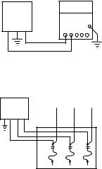
SURGE ARRESTERS IN CONTROL BOX
Grounding: When the box has a surge arrester, it MUST be grounded, metal to metal, all the way to the water strata for the arrester to be effective. Grounding the arrester to a driven ground rod provides little or no protection for the motor.
NOTICE: Surge arresters DO NOT protect against direct lightning strikes.
Install grounded surge arresters to protect pump from high voltage surges. Install arrester on the incoming power line to control box or pressure switch, as close to pump motor as possible. See Figures 1 and 2 for installation wiring diagrams for arresters.
NOTICE: Ground the arrester with a No. 10 or larger bare wire. Ground according to local code requirements.
NOTICE: If surge arresters wired into the control box are against local electrical code, contact power company for correct wiring information.
4
LIQUID LEVEL (PUMP DOWN) CONTROLS:
Use pump down controls on wells with low flow to prevent pumping well dry. See Wiring diagrams, Pages 8 through 12, for proper installation.
NOTICE: Ground controls according to local code requirements.
TABLE II: Recommended Fusing Data - 60
Hz., Single Phase, 3 Wire Standard Submersible
Pump Motors
|
|
Motor Winding |
Max |
Locked |
Fuze Size |
|
|
Volts/ |
Resistance-Ohms |
Load |
Rotor |
Standard/ |
|
HP |
Hz/Ph |
R to Y |
B to Y |
Amps |
Amps |
Dual Element |
|
|
|
|
|
|
|
1/2 |
115/60/1 |
4.1-5.1 |
1.0-1.3 |
12.0 |
50.5 |
35/20 |
|
|
|
|
|
|
|
1/2 |
230/60/1 |
16.7-20.5 |
4.2-5.2 |
6.0 |
23.0 |
20/10 |
|
|
|
|
|
|
|
3/4 |
230/60/1 |
11.0-13.4 |
3.0-3.6 |
8.0 |
34.2 |
25/15 |
|
|
|
|
|
|
|
1 |
230/60/1 |
10.1-12.3 |
2.2-2.7 |
9.8 |
41.8 |
30/20 |
Recommended Fusing Data - 60 Hz., Single
Phase, 3 Wire Capacitor Run Submersible
Pump Motors
|
|
Motor Winding |
Max |
Locked |
Fuze Size |
|
|
Volts/ |
Resistance-Ohms |
Load |
Rotor |
Standard/ |
|
HP |
Hz/Ph |
R to Y |
B to Y |
Amps |
Amps |
Dual Element |
|
|
|
|
|
|
|
1-1/2 |
230/60/1 |
6.2-12.0 |
1.5-2.3 |
11.5 |
52.0 |
35/20 |
|
|
|
|
|
|
|
2 |
230/60/1 |
5.2-7.15 |
1.6-2.3 |
13.2 |
51.0 |
30/20 |
|
|
|
|
|
|
|
3 |
230/60/1 |
3.0-4.9 |
0.9-1.5 |
17.0 |
82.0 |
45/30 |
|
|
|
|
|
|
|
5 |
230/60/1 |
2.1-2.8 |
0.68-1.0 |
27.5 |
121.0 |
80/45 |
|
|
|
|
|
|
|
Red to Yellow = start winding resistance; Black to Yellow = main winding resistance.
Surge
Arrester Control
Box
L1 L2 R Y B
TABLE III: Recommended Fusing Data - 60 Hz., Single Phase 2 Wire Submersible Pump Motors
|
|
Motor Winding |
Max |
Locked |
Fuze Size |
|
Volts/ |
Resistance |
Load |
Rotor |
Standard/ |
HP |
Hz/Ph |
Ohms |
Amps |
Amps |
Dual Element |
|
|
|
|
|
|
1/2 |
115/60/1 |
1.0-1.3 |
12.0 |
64.4 |
35/20 |
|
|
|
|
|
|
1/2 |
230/60/1 |
4.2-5.2 |
6.0 |
32.2 |
20/10 |
|
|
|
|
|
|
3/4 |
230/60/1 |
3.0-3.6 |
8.0 |
40.7 |
25/15 |
|
|
|
|
|
|
1 |
230/60/1 |
2.2-2.7 |
9.8 |
48.7 |
30/20 |
|
|
|
|
|
|
1-1/2 |
230/60/1 |
1.5-1.9 |
13.1 |
66.6 |
35/20 |
|
|
|
|
|
|
NOTE: 2 Wire motor leads are not color coded. Overload is located in motor and cannot be tested from above ground.
TABLE IV: Recommended Fusing Data - 60 Hz., 3 Phase Submersible Pump Motors
|
|
Max Input |
Line to |
Locked |
Fuze Size |
|
Volts/ |
(S.F. Load) |
Line |
Rotor |
Standard/ |
HP |
Hz/Ph |
Amps |
Resistance |
Amps |
Dual Element |
|
|
|
|
|
|
1-1/2 |
230/60/3 |
5.9 |
3.2-4.0 |
33.2 |
15/10 |
|
460/60/3 |
3.0 |
13.0-16.0 |
16.6 |
8/5 |
|
575/60/3 |
2.4 |
20.3-25.0 |
13.3 |
6/4 |
|
|
|
|
|
|
2 |
230/60/3 |
8.1 |
2.4-3.0 |
46.6 |
25/15 |
|
460/60/3 |
4.1 |
9.7-12.0 |
23.3 |
15/8 |
|
575/60/3 |
3.2 |
15.1-18.7 |
18.6 |
10/5 |
|
|
|
|
|
|
3 |
230/60/3 |
10.8 |
1.8-2.2 |
61.9 |
30/20 |
|
460/60/3 |
5.4 |
7.0-8.7 |
31.0 |
15/10 |
|
575/60/3 |
4.3 |
10.9-13.6 |
24.8 |
15/8 |
|
|
|
|
|
|
5 |
230/60/3 |
17.7 |
0.93-1.2 |
106.0 |
50/30 |
|
460/60/3 |
8.9 |
3.6-4.4 |
53.2 |
25/15 |
|
575/60/3 |
7.1 |
5.6-6.9 |
42.6 |
20/15 |
|
|
|
|
|
|
7-1/2 |
230/60/3 |
26.0 |
0.61-0.75 |
164.0 |
80/45 |
|
460/60/3 |
13.0 |
2.4-3.4 |
81.9 |
40/25 |
|
575/60/3 |
10.4 |
3.5-5.1 |
65.5 |
30/20 |
|
|
|
|
|
|
10 |
460/60/3 |
18.5 |
1.8-2.3 |
116.0 |
60/45 |
|
575/60/3 |
14.8 |
2.8-3.5 |
92.8 |
45/35 |
FIGURE 1 – Typical 3 Wire, Single Phase, 230 Volt Surge Arrester
Line
Surge
Arrester
L1 |
L2 |
L3 |
T1 T2 T3
FIGURE 2 - Three Phase Surge Arrester (650
Volt Maximum)
(650 olt Maximum)
5

TABLE V: Cable Length in Feet
1 Phase, 2 or 3 Wire Cable, 60 Hz. Copper Wire Size (Service to Motor)
Volts |
HP |
14 |
12 |
10 |
8 |
6 |
4 |
3 |
2 |
1 |
0 |
|
|
|
|
|
|
|
|
|
|
|
|
115V |
1/2 |
100 |
160 |
250 |
390 |
620 |
960 |
1190 |
1460 |
1780 |
2160 |
|
|
|
|
|
|
|
|
|
|
|
|
|
1/2 |
400 |
650 |
1020 |
1610 |
2510 |
3880 |
4810 |
5880 |
7170 |
8720 |
|
3/4 |
300 |
480 |
760 |
1200 |
1870 |
2890 |
3580 |
4370 |
5330 |
6470 |
|
1 |
250 |
400 |
630 |
990 |
1540 |
2380 |
2960 |
3610 |
4410 |
5360 |
230V |
1-1/2 |
190 |
310 |
480 |
770 |
1200 |
1870 |
2320 |
2850 |
3500 |
4280 |
|
2 |
150 |
250 |
390 |
620 |
970 |
1530 |
1910 |
2360 |
2390 |
3620 |
|
3 |
120* |
190 |
300 |
470 |
750 |
1190 |
1490 |
1850 |
2320 |
2890 |
|
5 |
– |
– |
180 |
280 |
450 |
710 |
890 |
1110 |
1390 |
1740 |
|
|
|
|
|
|
|
|
|
|
|
|
|
|
|
|
|
|
|
|
|
|||
3 Phase, 3 Wire Cable, 60 Hz. |
|
|
|
|
|
|
|
|
|||
Volts |
HP |
14 |
12 |
10 |
8 |
6 |
4 |
3 |
2 |
1 |
0 |
|
|
|
|
|
|
|
|
|
|
|
|
|
|
|
1-1/2 |
420 |
670 |
1060 |
1670 |
2610 |
4050 |
5030 |
6160 |
7530 |
9170 |
|
|
2 |
320 |
510 |
810 |
1280 |
2010 |
3130 |
3890 |
4770 |
5860 |
7170 |
|
230V |
3 |
240 |
390 |
620 |
990 |
1540 |
2400 |
2980 |
3660 |
4480 |
5470 |
|
5 |
140* |
230 |
370 |
590 |
920 |
1430 |
1790 |
2190 |
2690 |
3290 |
||
|
||||||||||||
|
7-1/2 |
– |
160* |
260 |
420 |
650 |
1020 |
1270 |
1560 |
1920 |
2340 |
|
|
10 |
– |
– |
190* |
310 |
490 |
760 |
950 |
1170 |
1440 |
1760 |
|
|
|
|
|
|
|
|
|
|
|
|
|
|
|
1-1/2 |
1700 |
2710 |
4270 |
6730 |
– |
– |
– |
– |
– |
– |
|
|
2 |
1300 |
2070 |
3270 |
5150 |
8050 |
– |
– |
– |
– |
– |
|
460V |
3 |
1000 |
1600 |
2520 |
3970 |
6200 |
– |
– |
– |
– |
– |
|
5 |
590 |
950 |
1500 |
2360 |
3700 |
5750 |
– |
– |
– |
– |
||
|
||||||||||||
|
7-1/2 |
420 |
680 |
1070 |
1690 |
2640 |
4100 |
5100 |
6260 |
7680 |
– |
|
|
10 |
310 |
500 |
790 |
1250 |
1960 |
3050 |
3800 |
4650 |
5750 |
7050 |
|
|
|
|
|
|
|
|
|
|
|
|
|
|
|
1-1/2 |
2620 |
4180 |
6580 |
– |
– |
– |
– |
– |
– |
– |
|
|
2 |
2030 |
3250 |
5110 |
8060 |
– |
– |
– |
– |
– |
– |
|
575V |
3 |
1580 |
2530 |
3980 |
6270 |
5750 |
– |
– |
– |
– |
– |
|
5 |
920 |
1480 |
2330 |
3680 |
5750 |
– |
– |
– |
– |
– |
||
|
||||||||||||
|
7-1/2 |
660 |
1060 |
1680 |
2650 |
4150 |
– |
– |
– |
– |
– |
|
|
10 |
490 |
780 |
1240 |
1950 |
3060 |
4770 |
5940 |
– |
– |
– |
|
|
|
|
|
|
|
|
|
|
|
|
|
*Meets NEC for individual conductor 60°C cable. Only length without * meet NEC for jacketed 60°C cable. Local code requirements may vary.
Table V NOTES:
1.Sizes given are for copper wire. For aluminum wire, go two sizes larger. For example, if table lists #12 (3mm2) copper wire, use #10 (5mm2) aluminum wire.
2.For reliable 3 Phase starter operation, length of wire between starter and service entrance should be not more than 25% of total wire length.
6
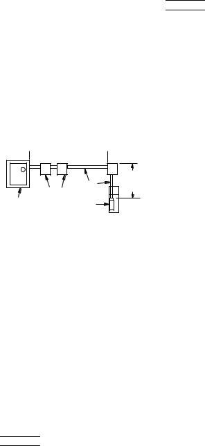
Calculating Cable size when two different sizes can be used.
Sometimes conditions make it desirable to use more than one size cable in an installation.
For example: Replace a pump with a 3 HP, 230 volt, single phase motor, with the motor setting at 310' down the well and with 160' of #10 cable buried between the service entrance and the well head. In order to avoid replacing the buried cable, the question is: What size cable is required in the well? Calculate as follows:
1.According to Table V, a total of 300' of #10 cable is allowed to power the 3 HP motor. The per cent of this total that has been used by the 160' of cable in the buried run is: 160'/300' = .533 = 53.3%.
 160 Ft. AWG 10
(53.3% of Allowable Cable)
310 Ft. AWG 6
(41.3% of
|
Cable |
Allowable |
|
Pump |
Cable) |
Service Entrance |
Controls |
|
3 HP (2.2 kw) |
|
|
(Main Fuse Box |
|
|
230V 1Ph Motor |
|
|
From Meter) |
|
|
|
218 0993 |
|
|
|
2.With 53.3% of the allowable cable already used, 46.7% of the total length is left for use in the well. To avoid running a cable that is too long and lowering the voltage to the motor, we have to find a cable size large enough so that 310' is less than 46.7% of the total length allowed for that size.
3.Trying #8 cable, Table V shows that the total allowable length for a 3 HP motor is 470'.
470' x 46.7% = 470' x .467 = 219.5' This is not long enough.
4.Trying #6 cable, Table V shows that the total allowable length is 750'.
750' x 46.7% = 750' x .467 = 350.25'
This is longer than needed. Therefore, #6 cable can be used for the 310' of cable in the well.
Any combination of sizes can be used, provided that the total percentage of the length of the two sizes of cable does not exceed 100% of the allowed lengths.
INSTALLATION WIRING DIAGRAMS - SINGLE PHASE, 3 WIRE


 For motors of 1-1/2 HP and above, use magnetic starter to avoid damage to pressure switch. Consult factory for wiring information.
See Page 11 for 2 Wire Hookup


 Hazardous voltage. Can shock, burn, or kill.
Ground control box, all metal plumbing, and motor frame with copper wire in compliance with local codes. Use a ground wire at least as large as the wires supplying power to motor.
Permanently close all unused openings in this and other equipment.
Disconnect power to control box before working on or around control box, pipes, cable, pump, or motor.
To be sure that starting relay will function and that overload will not “nuisance trip”, install control box vertically with top side up.
Wire control box as shown on pages 8 through 12. Pump will not operate without control box, and deluxe boxes require a switch or a jumper lead between ‘SW’ and ‘L2’ terminals. Operation without control box will burn out motor.
Installation must include circuit and component protection which meet local code and United States National Electrical Code requirements.
If main overload trips, look for:
1.Shorted Capacitor
2.Voltage Problems
3.Overloaded or locked pump.
NOTICE: Match motor to control box as shown below. Franklin motor and control box model numbers may include additional suffix numbers to the right of the numbers shown here. These additional numbers are not important for control box selection.
TABLE VI: Control Box Selection
|
|
Motor |
Control |
|
HP |
Voltage |
No. |
Box No. |
|
|
|
|
|
|
1/2 |
115 |
214304 |
28010449 |
|
214504 |
||||
|
|
|
||
|
|
|
|
|
1/2 |
230 |
214305 |
28010549 |
|
214505 |
||||
|
|
|
||
|
|
|
|
|
3/4 |
230 |
214307 |
28010749 |
|
214507 |
||||
|
|
|
||
|
|
|
|
|
1 |
230 |
214308 |
28010849 |
|
214508 |
||||
|
|
|
||
|
|
|
|
|
1-1/2 |
230 |
224300 |
28230081 |
|
|
|
|
|
|
2 |
230 |
224301 |
28230181 |
|
28230183 |
||||
|
|
|
||
|
|
|
|
|
3 |
230 |
224302 |
28230281 |
|
28230283 |
||||
|
|
|
||
|
|
|
|
|
5 |
230 |
224303 |
28211381 |
|
28211383 |
||||
|
|
|
||
|
|
|
|
If start overload or both overloads trip(s), replace start relay. Reset and analyze for tripping cause. To avoid motor burnout, do not remove or short circuit overload protection.
7

CHECKING PROCEDURE (ALL BOXES):


 Hazardous voltage. Can shock, burn, or cause death. Disconnect power to control box before doing these check procedures.
A.General Procedures. (Power to control box disconnected)
1.Disconnect line.
2.Inspect for damaged or burned parts, loose connections, etc.
3.Check for misconnections against diagram in control box.
4.If box is too hot, circuit breakers may trip or fuses blow. Ventilate or shade box. Move away from heat source.
5.If problem has not been found, check motor and control box. Use test procedures that follow.
B.Ground (Insulation Resistance) Test. (Power to control box disconnected)
1.Ohmmeter Setting: Highest scale (usually Rx100K or Rx10,000).
2.Terminal Connections: One ohmmeter lead to “Ground” screw on control box and touch other lead to each of the terminals on terminal board.
3.Ohmmeter Reading: Pointer should remain at infinity (∞) and not deflect.
C.Capacitor Tests. (Power to control box disconnected)


 Risk of electric shock. Short capacitor across terminals before testing.
1.Ohmmeter Setting: Rx1000.
2.Terminal Connections: Connect ohmmeter leads to black and orange wires out of capacitor case.
3.Ohmmeter Reading: Pointer should swing toward “zero” and “float” back to (∞).
Capacitor is shorted if pointer does not move back to (∞), open if it does not move from (∞).
4.To reset capacitor, reverse ohmmeter connection to capacitor terminals.
D.Triac Test. (Solid state switch only)
1.Ohmmeter Setting: Rx1000.
2.Connect the leads to “R” (start) terminal and to orange lead terminal on start switch.
3.Ohmmeter reading: Infinity (∞).
E.Coil Test. (Solid state switch only)
1.Ohmmeter Setting: Rx1.
2.Connect leads to “Y” (common) and L2 terminal and to orange lead terminal on start switch.
3.Ohmmeter reading: Infinity (∞).
Installation Wiring Diagrams – Single Phase, 3 Wire


 For motors of 1-1/2 HP and above, use magnetic starter to avoid damage to pressure switch. Consult factory for wiring information.
SINGLE PHASE - 1/2 HP THRU 5 HP STANDARD |
SINGLE PHASE - 1/2 HP THRU 5 HP STANDARD |
|||
CONTROL BOX WITH ADEQUATE RATED |
CONTROL BOX WITH PRESSURE SWITCH (One pump |
|||
|
PRESSURE SWITCH |
for 2 houses) With adequate rated pressure switch |
||
To Line |
Ground |
To Line |
To Line |
Ground |
|
||||
CONTROL
BOX
L1 L2 R Y B |
L1 M1
L2 M2
Fused
Disconnect
Switch Pressure
Switch
Red
Yellow
Black
Ground
Well
Casing
355 0893
Fused |
Pressure |
Disconnect |
|
Switch |
Switch |
|
L1 |
M1 |
|
|
L2 |
M2 |
|
L1 |
M1 |
|
|
L2 |
M2 |
|
|
Pressure |
|
|
|
Switch |
|
CONTROL |
|
|
|
BOX |
|
Aux. Relay |
L1 L2 R Y |
B |
|
or Equivalent |
|
|
|
|
Red |
|
|
|
Yellow |
|
|
|
Black |
|
|
Ground
Well
Casing
359 0893
Follow color coding when connecting control box (Yellow to Y, Red to R, Black to B).
8
 Loading...