

Page 1
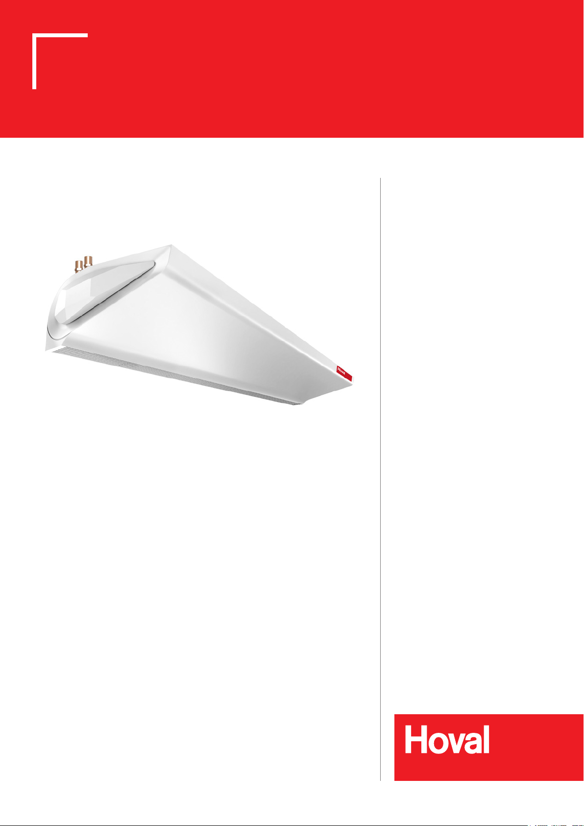
TopVent® TW
Design, installation and operation
TopVent® TW
Air curtain
Page 2
TopVent® TW
Design, installation and operation
1 Use 3
1.1 Intended use .................................................................. 3
1.2 User group ..................................................................... 3
2 Safety 4
2.1 Symbols ......................................................................... 4
2.2 Operational safety .......................................................... 4
3 Construction and operation 5
3.1 Unit construction ............................................................ 5
3.2 Operating modes ........................................................... 6
4 Technical data 7
Content
4.1 Application limits ............................................................ 7
4.2 Flow rate, product parameters ....................................... 7
4.3 Heat output .................................................................... 7
4.4 Sound data .................................................................... 8
4.5 Dimensions and weights ................................................ 8
4.6 Specication text ............................................................ 8
5 Transport and installation 9
5.1 Delivery .......................................................................... 9
5.2 Requirements for the installation site ............................. 9
5.3 Installation.................................................................... 10
5.4 Hydraulic installation .................................................... 13
5.5 Electrical installation .................................................... 14
6 Operation 16
6.1 Initial commissioning .................................................... 16
6.2 Operation ..................................................................... 16
7 Maintenance and repair 17
7.1 Safety .......................................................................... 17
7.2 Maintenance ................................................................ 17
7.3 Repair .......................................................................... 17
8 Dismantling 18
9 Disposal 18
4 216 285- en-02
2
Page 3
TopVent® TW
Design, installation and operation
1 Use
1.1 Intended use
TopVent® TW units are air curtains for protecting entrance areas against the cold.
They have the following functions:
■ Heating (with connection to a hot water supply)
■ Recirculation operation
■ Air distribution via outlet nozzle
Intended use also includes compliance with the operating instructions. Any usage
over and above this use is considered to be not as intended. The manufacturer
can accept no liability for damage resulting from improper use.
1.2 User group
Use
The units are only allowed to be installed, operated and maintained by authorised
and instructed personnel who are well acquainted with the units and are informed
about possible dangers.
The operating instructions are for operating engineers and technicians as well as
specialists in building, heating and ventilation technology.
4 216 285- en-02
3
Page 4
TopVent® TW
Design, installation and operation
2 Safety
2.1 Symbols
Caution
This symbol warns against risk of injury. Please heed all instructions designated by this symbol to prevent injuries and/or death.
Attention
This symbol warns against property damage. Please heed the respective
instructions to prevent risk of damage to the unit and its functions.
Notice
This symbol denotes information about the economic use of the equipment
or special tips.
Safety
2.2 Operational safety
The unit is built to conform to the state-of-the-art and is operationally safe.
Despite every precaution being taken, potential and not immediately obvious risks
always remain, for example:
■ Dangers when working with the electrical system
■ Parts (e.g. tools) can fall down below when working on the ventilation unit.
■ Malfunctions as a result of defective parts
■ Hazards from hot water when working on the hot water supply
Therefore:
■ Please read the operating instructions before unpacking, installing, commis-
sioning and before maintaining the equipment.
■ Store the operating instructions so that they are easily accessible.
■ Observe any attached information and warning signs.
■ Immediately replace damaged or removed informational and warning signs.
■ Follow the local safety and accident prevention regulations at all times.
■ Disconnect the power supply and wait at least 5 minutes before opening the
unit.
■ When working in the unit, take precautions against unprotected, sharp metal
edges.
■ The unit may only be installed, operated and serviced by authorised, trained
and instructed skilled personnel:
– Specialists as dened by these operating instructions are those persons
who, based on their training, knowledge and experience as well as their
knowledge of the relevant regulations and guidelines, can carry out the work
assigned to them and recognise potential hazards.
■ Unauthorised reconguration or modication of the unit is not permitted.
4 216 285- en-02
4
Page 5
TopVent® TW
Design, installation and operation
3 Construction and operation
The TopVent® TW serves as an air curtain to protect entrance areas against the
cold. The unit is installed over or next to the door. It takes in room air, heats it by
means of the heating coil and blows it back into the room at a high speed. This
creates a barrier of owing air, which protects the indoor climate from external
inuences.
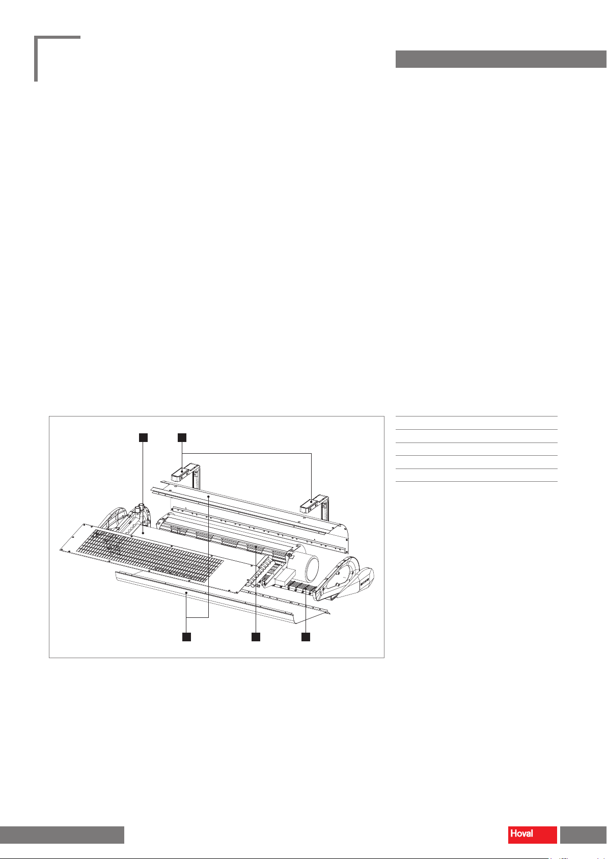
There are 3 unit sizes, which are each equipped with an innitely variable fan and
a custom-made heating coil.
3.1 Unit construction
The TopVent® TW consists of the following components:
■ Heat exchanger consisting of copper tubes and aluminium ns
■ Tangential fan with energy-saving EC motor and ow-optimised rotor, innitely
variable, maintenance-free and quiet with a high degree of eciency
■ Compact casing made of galvanised sheet steel
■ Suspension set for vertical or horizontal installation of the unit
■ Outlet nozzle
Construction and operation
1 2
3 4
1
Heat exchanger
■
2
Suspension set
■
3
Casing
■
4
Fan
■
5
Outlet nozzle
■
5
Fig. 1: Unit construction
4 216 285- en-02
5
Page 6
TopVent® TW
Design, installation and operation
3.2 Operating modes
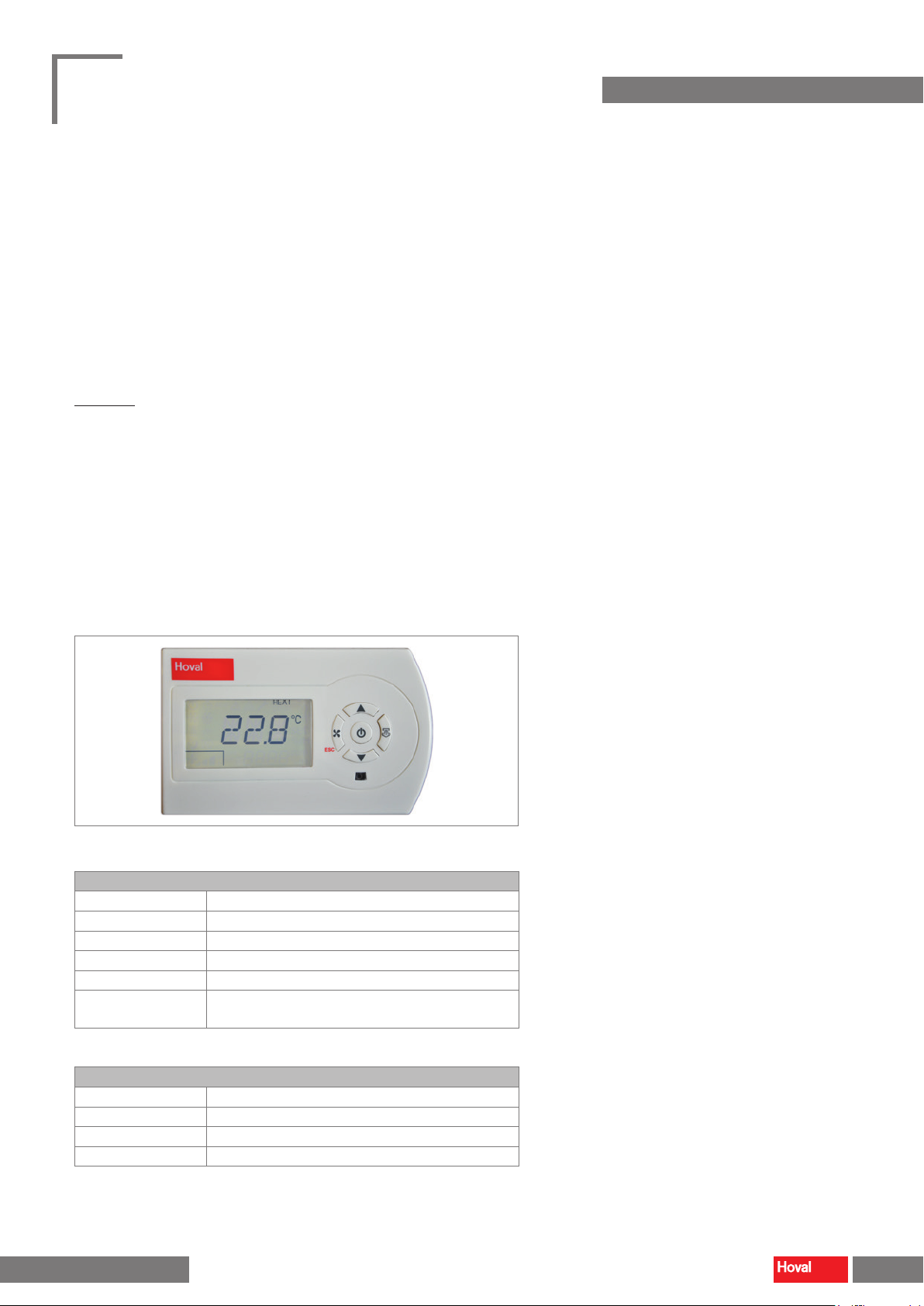
The TopVent® TW operates in on/o mode. The EasyTronic EC room temperature
controller regulates the operation of the unit.
EasyTronic EC
The EasyTronic EC is a room temperature controller with a timer. A maximum of
10 TopVent
Functions
■ Recording the room temperature with the integrated temperature sensor
■ Room temperature control in on/o mode: If the room temperature falls below
the setpoint value, the connected TopVent
setpoint value, the units switch o again.
■ Lowering of the room temperature setpoint value via week programme
■ Controlling the TopVent
are switched on via door contact if the door is open (digital input).
■ Adjusting the fan speed: The required speed can be innitely adjusted.
■ Pump or valve control: The EasyTronic EC provides a signal for switching a
pump or a valve (digital output).
®
units can be connected to 1 controller.
– Optional: Recording the room temperature with the external temperature
sensor
®
units switch on. Upon reaching the
®
units using a door contact switch: The connected units
Construction and operation
Fig. 2: EasyTronic EC room temperature controller
EasyTronic EC
Power supply 110…230 VAC, ±10%, 50/60 Hz
Power consumption max. 1.3 W
Temperature range 0...50 °C
Dimensions (W x H x D) 128 × 80 × 56 mm
Protection rating IP 30, class 2
Installation In a flush-mounted box (spacing between mounting holes
83.5 mm) or on the supplied base
Table 1: Technical data EasyTronic EC
Room temperature sensor ET-R
Temperature range - 30...+ 70 °C
Dimensions (W x H x D) 93 × 70 × 46 mm
Protection rating IP 65
Installation in plastic casing for wall mounting
Table 2: Technical data EasyTronic EC
4 216 285- en-02
6
Page 7
TopVent® TW
Design, installation and operation
4 Technical data
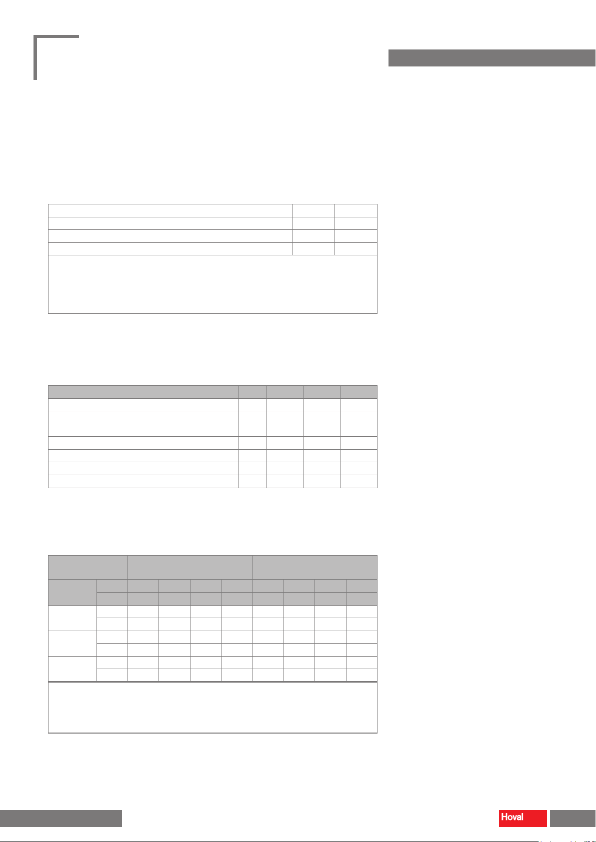
4.1 Application limits
Maximum operating pressure 1600 kPa
Maximum heating medium temperature 90 °C
Maximum supply air temperature 60 °C
Maximum extract air temperature 50 °C
The units cannot be used in:
■ Areas where there is danger of explosion
■ Places with a corrosive or aggressive environment
■ Damp locations
■ Spaces with a large amount of dust
Table 3: Application limits
Technical data
4.2 Flow rate, product parameters
Type TW-2 TW-3 TW-5
Nominal air flow rate m³/h 1850 3100 4400
Power consumption kW 0.15 0.18 0.26
Current consumption A 1.10 1.30 1.90
Supply voltage VAC 230 230 230
Frequency Hz 50 50 50
Max. mounting height m 3.7 3.7 3.7
Max. horizontal reach m 3.7 3.7 3.7
Table 4: Technical data
4.3 Heat output
Temperature of the
heating medium
Type t
room
Q tS∆p
°C kW °C kPa l/h kW °C kPa l/h
TW-2 15 11.9 33.8 0.2 500 4.3 21.8 0.04 200
20 10.5 36.8 0.2 500 3.5 25.6 0.03 200
TW-3 15 22.1 35.9 1.2 1000 12.1 26.4 0.4 500
20 19.8 39.0 0.9 900 9.5 29.1 0.3 400
TW-5 15 32.6 36.7 3.1 1400 18.9 27.5 1.3 800
20 29.3 39.8 2.6 1300 15.4 30.4 0.9 700
Legend: t
Table 5: Heat output
= Room air temperature
room
Q = Heat output
= Supply air temperature
t
S
= Water pressure drop
∆p
W
= Water quantity
m
W
80/60 °C 60/40 °C
m
W
W
Q tS∆p
W
m
W
4 216 285- en-02
7
Page 8
484
229
TopVent® TW
Design, installation and operation
4.4 Sound data
Type TW-2 TW-3 TW-5
Sound pressure level (at a distance of 5 m)
Total sound power level dB(A) 79.5 80.5 80.5
1)
Reference: semi-open room
Table 6: Sound levels
1)
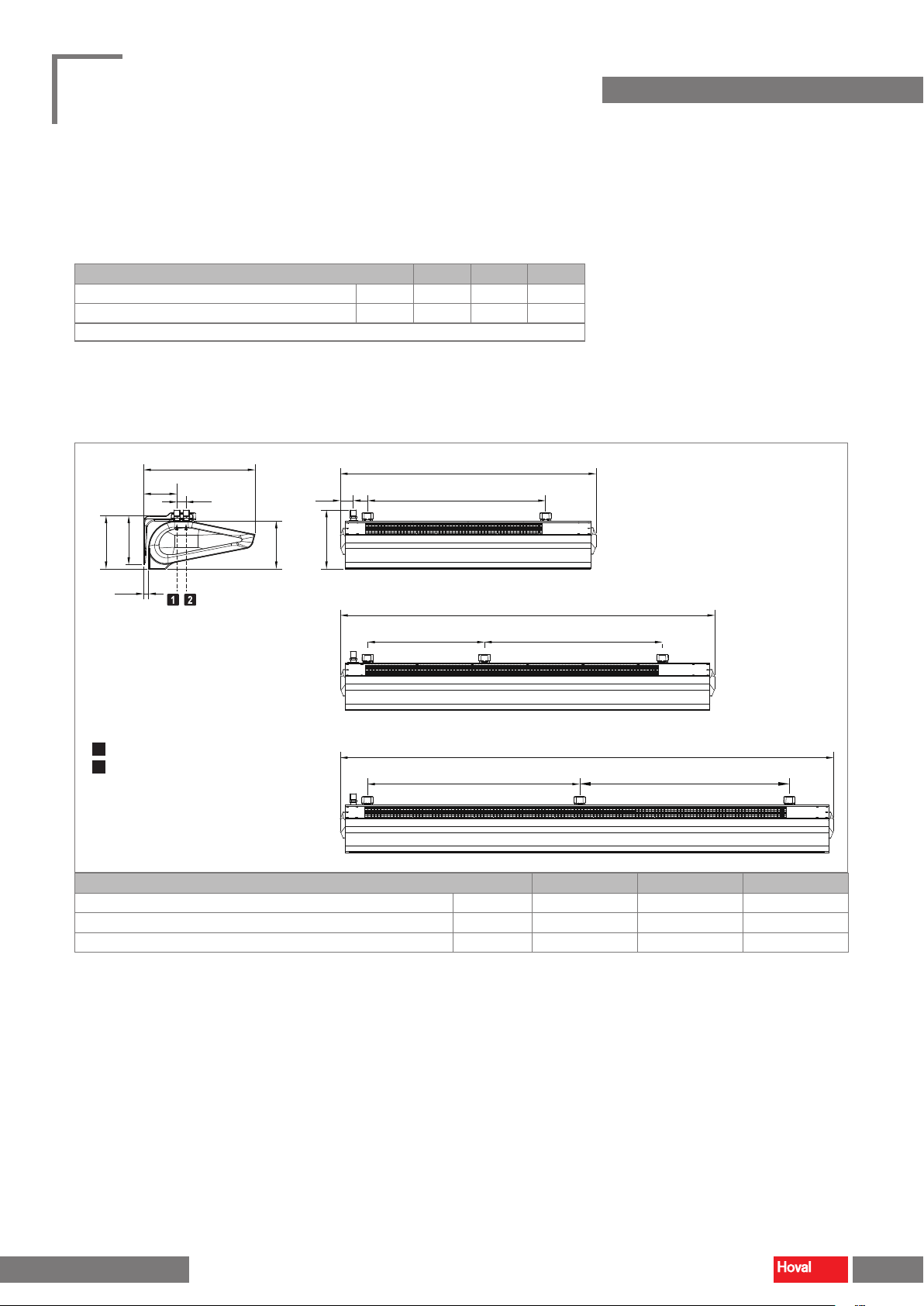
4.5 Dimensions and weights
145
40
dB(A) 57.5 58.5 58.5
1100
56
772
Technical data
212
22
1
Return
2
Flow
Type TW-2 TW-3 TW-5
Water content of the coil l 1.6 2.6 3.6
Connection (external thread) " R ¾ R ¾ R ¾
Weight kg 22.6 31.2 38.8
Table 7: Dimensions and weights
207
255
507
1626
772
2142
921 910
4.6 Specification text
TopVent® TW – Air curtain
Sturdy casing made of galvanised sheet steel, including suspension set for horizontal or vertical installation. Heat exchanger consisting of copper tubes and
aluminium ns; tangential fan with highly ecient EC motor, innitely variable,
maintenance-free and quiet, protection rating IP 20, insulation class F; rearmounted terminal box; air outlet nozzle and side cover consisting of ABS.
4 216 285- en-02
8
Page 9
3000
3700 7400
TopVent® TW
Design, installation and operation
5 Transport and installation
Caution
Risk of injury from incorrect handling. Transport, assembly and installation
work may only be performed by specialists. Observe safety and accident
prevention regulations.
5.1 Delivery
TopVent® TW units are packed in cardboard boxes and delivered on a pallet.
■ The scope of delivery includes:
– TopVent
– Retaining brackets (x2 for TW-2, x3 for TW-3/5)
– Retainer covers (x2 for TW-2, x3 for TW-3/5)
– M8 screws with washers (x4 for TW-2, x6 for TW-3/5)
■ Ensure that the unit is undamaged.
■ Report any missing parts, wrong deliveries and possible transport damage
immediately in writing.
®
TW unit
Transport and installation
5.2 Requirements for the installation site
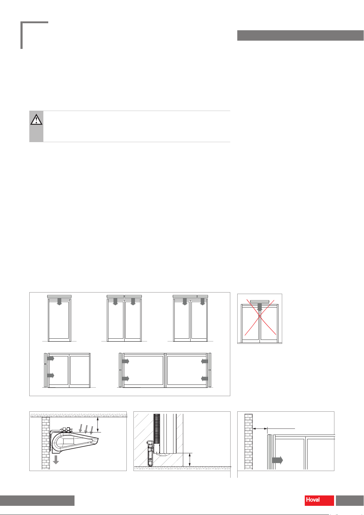
■ Position the units over or next to the door. The air ow must cover the entire
door width/height.
■ The minimum distance to the ceiling, the oor or the wall is 0.1 m.
■ All air inlet and air outlet openings must be freely accessible.
3700
2000 3000
3000
Fig. 3: Examples of horizontal and vertical installation (dimensions in mm)
3700
3000
3700
Fig. 4: The air ow must cover the entire opening.
≥ 0.1 m
≥ 0.1 m
≥ 0.1 m
Fig. 5: Minimum distance to the ceiling Fig. 6: Minimum distance to the oor Fig. 7: Minimum distance to the wall
4 216 285- en-02
9
Page 10
TopVent® TW
Design, installation and operation
5.3 Installation
Caution
Risk of injury caused by falling load and improper handling. During
installation:
– Wear protective equipment (safety helmet, safety goggles, safety shoes).
– Do not stand under suspended loads.
– Use cranes or forklifts with sucient load-bearing capacity.
Preparation
■ Make sure that the following items are on hand for the assembly:
– Installation platform
– Socket wrench, width 13
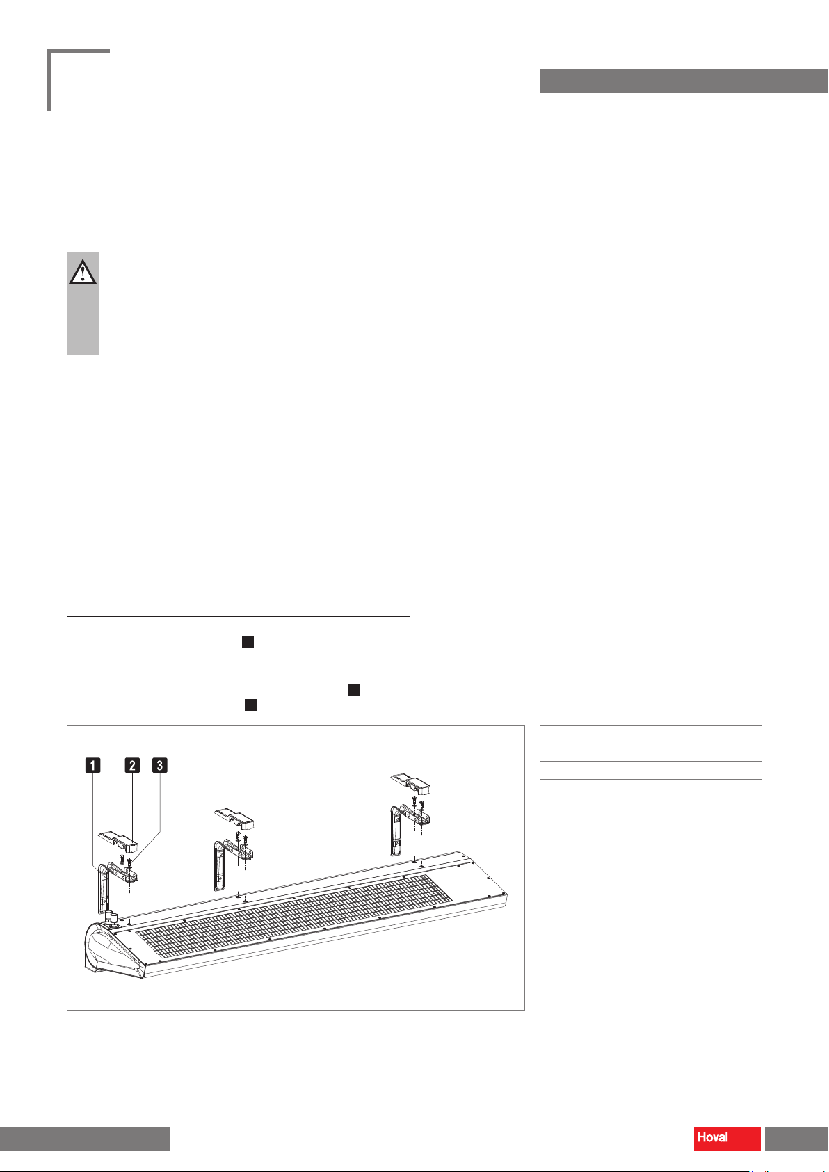
■ The installation variant 1 (horizontal unit, retaining brackets facing downwards)
is standard. The screws required for this variant are provided.
■ Additional material is required for the other installation variants:
– Variant 2 (horizontal unit, retaining brackets facing upwards):
M8x55 screws, x4 for TW-2, x6 for TW-3/TW-5
– Variant 3 (vertical unit):
M8x70 screws, x4 for TW-2, x6 for TW-3/TW-5
Transport and installation
Installation
Variant 1: horizontal unit, retaining brackets facing downwards
1
■ Install the retaining brackets
– Use the packaging box as a drilling template.
■ Install the unit on the retaining brackets:
– Lift the unit and secure it with the M8 screws
– Attach the retainer covers
on the wall.
2
.
3
.
1
Retaining bracket
■
2
Retainer cover
■
3
M8x20 screw with washer
■
4 216 285- en-02
Fig. 8: Horizontal installation with retaining brackets
facing downwards
10
Page 11
TopVent® TW
Design, installation and operation
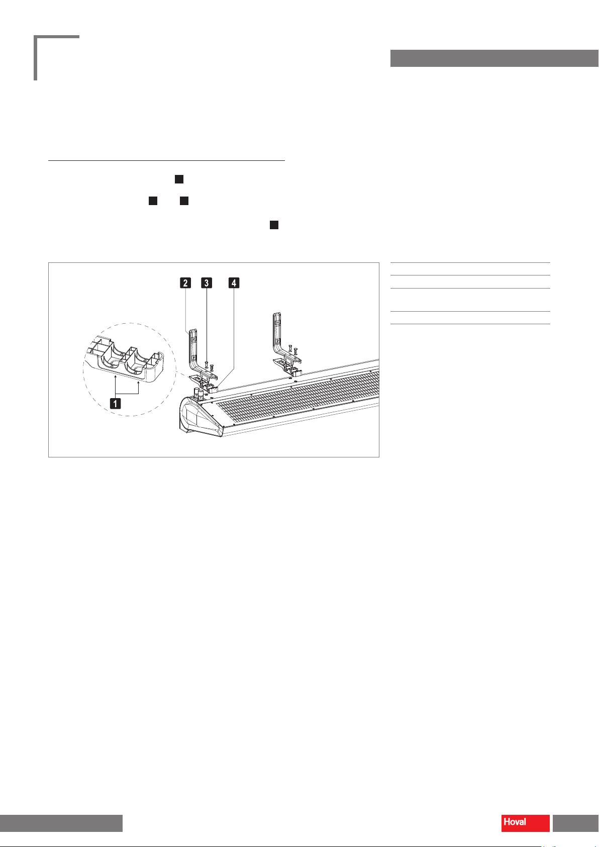
Variant 2: horizontal unit, retaining brackets facing upwards
2
■ Install the retaining brackets
– Take a hammer and a screw, and then punch 2 holes from the outside into
the retainer covers
– Attach the retainer covers onto the retaining brackets.
– Fasten the retaining brackets with the M8 screws
■ Install the unit on the wall.
– Use the packaging box as a drilling template.
4
on the unit:
(see 1 in Fig. 9).
3
onto the unit.
Transport and installation
1
Position of the holes
■
2
Retaining bracket
■
3
M8x55 screw with washer (not included in
■
the scope of delivery)
4
Retainer cover
■
Fig. 9: Horizontal installation with retaining brackets
facing upwards
4 216 285- en-02
11
Page 12
TopVent® TW
Design, installation and operation
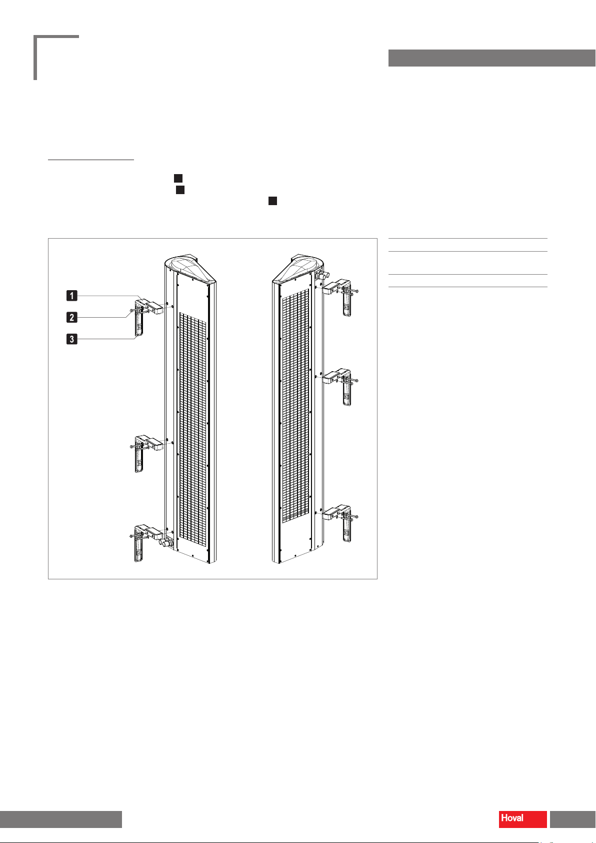
Variant 3: vertical unit
3
■ Install the retaining brackets
– Attach the retainer covers
– Fasten the retaining brackets with the M8 screws
■ Install the unit on the wall.
– Use the packaging box as a drilling template.
on the unit:
1
onto the retaining brackets.
2
onto the unit.
Transport and installation
1
Retainer cover
■
2
M8x70 screw with washer (not included in
■
the scope of delivery)
3
Retaining bracket
■
4 216 285- en-02
Fig. 10: Vertical installation
12
Page 13
TopVent® TW
Design, installation and operation
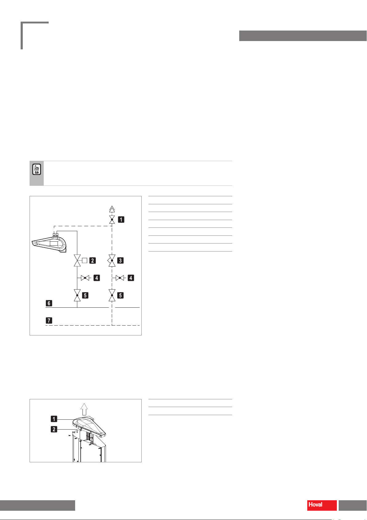
5.4 Hydraulic installation
■ Connect the heating coil according to the hydraulic circuit diagram.
■ Depending on local conditions, check whether compensators for linear expan-
sion are required for the supply and return lines and/or articulated connections
are required for the units.
■ Insulate the hydraulic lines.
■ Hydraulically aligned the individual units with one another within the control
group to ensure uniform pressure admission.
Attention
Danger of damaging the units. Do not fasten any loads to the coil, e.g. by
means of the ow or return lines.
1
Air vent with shut-off
■
2
Control valve
■
3
Balancing valve
■
4
Drain valves
■
5
Shut-off valves
■
6
Flow
■
7
Return
■
Transport and installation
Fig. 11: Connecting the heating coil
Ventilation
If the TopVent
door, the heating coil is ventilated automatically. If the unit is installed vertically on
the left side of the door (with the connection at the bottom), proceed as follows:
■ Unscrew the top side cover.
■ Ventilate the unit via the venting valve underneath.
■ Reinstall the side cover.
4 216 285- en-02
®
TW unit is installed horizontally or vertically on the right side of the
1
Side cover
■
2
Venting valve
■
Fig. 12: Connecting the heating coil
13
Page 14
230 VAC
230 VAC
TopVent® TW
Design, installation and operation
5.5 Electrical installation
Caution
Danger from electric current. The electrical installation is to be carried out
only by a qualied electrician.
Please note the following:
■ Observe all relevant regulations.
■ Choose the dimensions of the cable cross sections in line with the applicable
regulations.
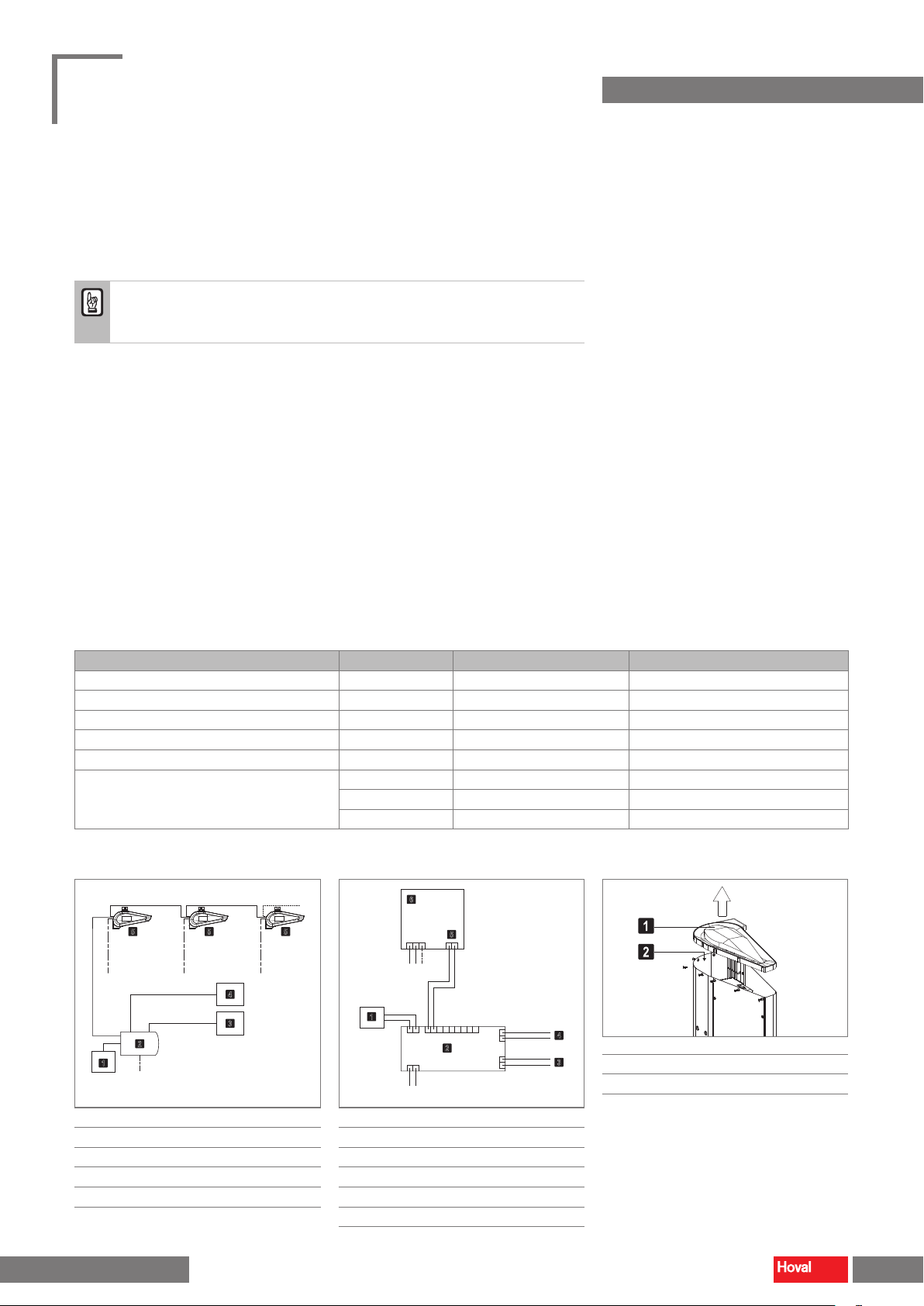
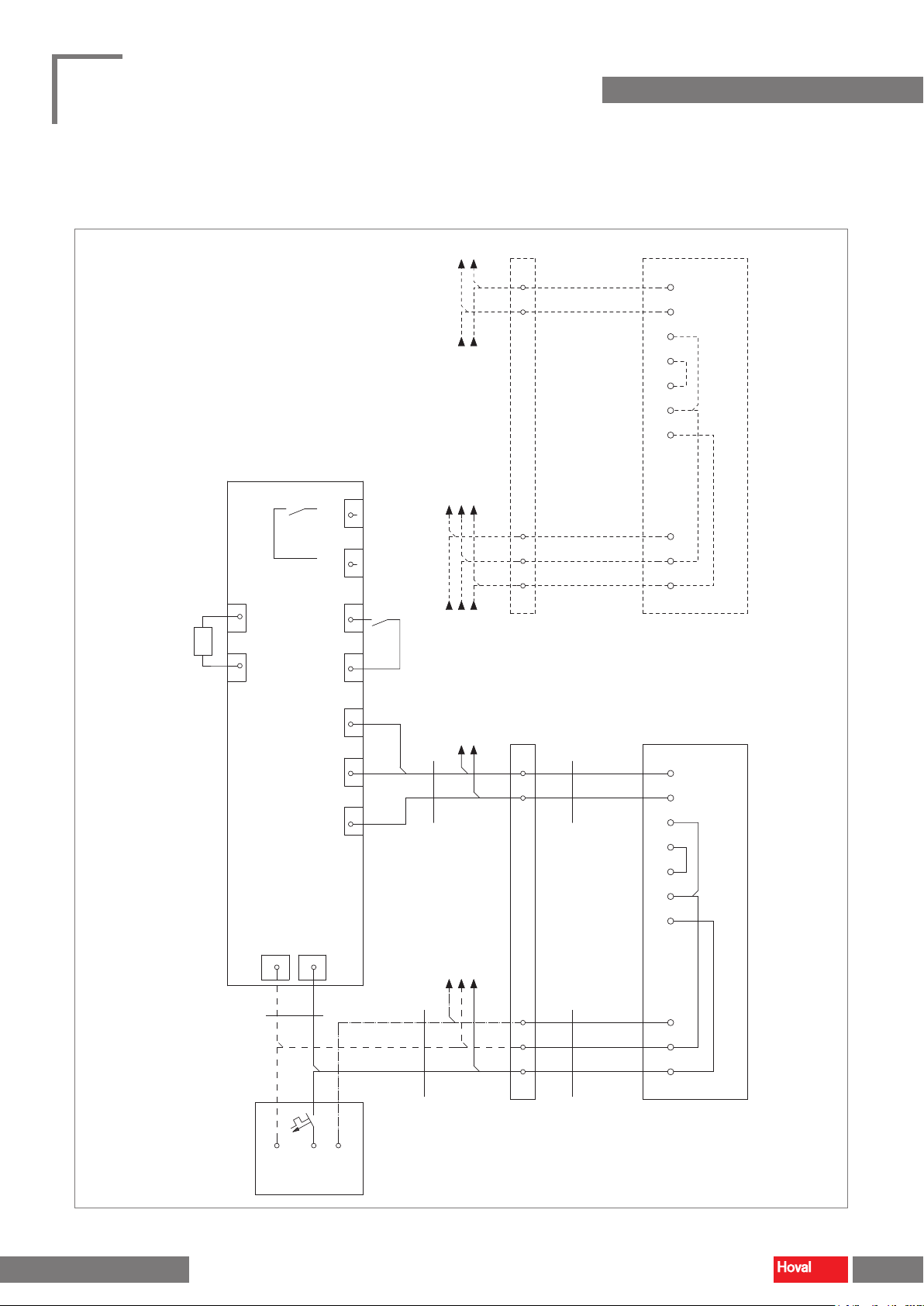
■ Carry out the electrical installation according to the wiring diagram.
■ Route the signal lines separately from the supply lines.
■ Secure all connections against working loose.
Proceed as follows:
■ Unscrew the top side cover.
■ Connect the power supply.
■ Connect the units with the EasyTronic EC room temperature controller.
■ Wire the external room temperature sensor to the EasyTronic EC.
■ Wire the door contact to the EasyTronic EC.
■ Wire the pump/valve control to the EasyTronic EC.
■ Reinstall the side cover.
Transport and installation
Designation Voltage Cable Comments
Power supply for TopVent
Power supply EasyTronic EC 1 × 230 V AC NYM 2 × 1.5 mm² (min.)
External room temperature sensor J-Y(St)Y 2 × 2 × 0.8 mm shielded, max. 30 m length
Fan control 0-10 V DC NYM 2 × 1.0 mm²
Door contact 24 V DC NYM 2 × 1.0 mm²
Pump / Valve control Volt-free NYM
Table 8: Cable list for on-site connections
5 5 5
230 VAC
2
1
1
External room temperature sensor
■
2
EasyTronic EC
■
3
Pump/valve
■
4
Door contact
■
5
TopVent® TW (max. 10)
■
Fig. 13: Conceptual diagram
4 216 285- en-02
®
230 VAC
230 VAC
4
3
1 × 230 V AC NYM 3 × 1.5 mm² (min.)
…
× 1.5 mm² (min.) max. 3 A
max. 230 V AC
max. 24 V DC
6
5
230 VAC
1
2
1
External room temperature sensor
■
2
EasyTronic EC
■
3
Pump / Valve control
■
4
Door contact
■
5
Fan control
■
6
TopVent® TW
■
Fig. 14: Connection diagram
4
3
1
Side cover
■
2
Terminal strip
■
Fig. 15: Unscrewing the side cover to access to the
terminal strip
14
Page 15
by the installer
Terminals
by the installer
TopVent® TW
Design, installation and operation
Transport and installation
1
2
1
2
DO2
COM
GND
AI1 GND
13 44
GND DI2
External room temperature sensor
GND
GND DI1
AO1
N
L
1
2
EasyTronic EC
32 3111 12
Pump or valve
16 14 10
NPEL1
NPEL1
Door contact
1
1 2
2x1 mm²
NPEL1
TW (max. 10)
®
L1 N PE 21
2
1 2
2x1 mm²
L1 N PE L1 N 3 9 10 Ai G
Fig. 16: Wiring diagram TopVent® TW
4 216 285- en-02
110…230 VAC
2x1.5 mm²
TW further TopVent
®
1 2 GNYE
1 2 GNYE
L1 N PE 21
L1 N PE L1 N 3 9 10 Ai G
TopVent
... A
L
N
PE
3G1.5 mm²
(min.)
3G1.5 mm²
(min.)
15
Page 16
TopVent® TW
Design, installation and operation
6 Operation
6.1 Initial commissioning
Attention
Risk of damage to property as a result of performing initial commissioning
on your own authority. Initial commissioning must be performed by the
manufacturer’s customer service technicians .
Preparing for initial commissioning:
Checklist:
■ Have all the media connections been made (electric cabling and water piping)?
■ Is the heating medium available?
■ Are the hydraulics aligned and balanced?
■ Are all the control components installed and wired?
■ Are all of the respective trade groups (installer, electrician, etc.) present at the
scheduled time?
■ Are the system operating personnel present for training at the scheduled time?
Operation
6.2 Operation
The system runs automatically according to the programmed room temperature,
the week programme and the door contact switch.
■ Observe the operating instructions for the control system.
■ Ensure free air outlet.
4 216 285- en-02
16
Page 17
TopVent® TW
Design, installation and operation
7 Maintenance and repair
Caution
Risk of injury from incorrect work. Maintenance work must be carried out by
trained personnel.
7.1 Safety
Before performing any work on the unit:
■ Turn the on-site main switch to the ‘O’ position and secure it against being
switched back on.
■ Wait at least 5 minutes after switching the unit o.
Caution
The use of condensers can pose a danger of fatal injury from directly
touching live parts even after the unit is switched o. Only open the unit
after waiting 5 minutes.
Maintenance and repair
■ Observe the accident prevention regulations.
■ Observe the particular dangers involved when working on electrical systems.
■ When working in the unit, take precautions against unprotected, sharp metal
edges.
■ Immediately replace damaged or removed informational and warning signs.
■ Following maintenance work, professionally reassemble all dismantled protec-
tive devices.
7.2 Maintenance
Maintenance schedule
Activity Interval
Cleaning the heat exchanger If required,
at least once per year before the heating season
Check function 1 x annually
Cleaning the heat exchanger
■ Carefully clean the heat exchanger with compressed air.
– Dismantle the air inlet grille for cleaning.
– Ensure that you do not damage the ns.
7.3 Repair
If repairs are necessary, contact the manufacturer’s customer service department.
4 216 285- en-02
17
Page 18
TopVent® TW
Design, installation and operation
8 Dismantling
Caution
Risk of injury caused by falling load and improper handling.
– Wear protective equipment (fall protection, safety helmet, safety shoes).
– Do not stand under suspended loads.
■ Disconnect the power supply to the unit.
■ Wait at least 5 minutes after switching the unit o.
Caution
The use of condensers can pose a danger of fatal injury from directly
touching live parts even after the unit is switched o. Only open the unit
after waiting 5 minutes.
Dismantling
■ Drain the heating medium circuit.
■ Dismantle all media connections.
■ Disconnect the unit from fastenings where applicable.
■ Remove the unit.
9 Disposal
■ Recycle metal components.
■ Recycle plastic parts.
■ Dispose of electric and electronic parts via hazardous waste.
■ If required, dispose of oil-fouled parts in accordance with local regulations.
4 216 285- en-02
18
Page 19
TopVent® TW
Design, installation and operation
Dismantling
4 216 285- en-02
19
Page 20
TopVent® TW
Operating instructions
International
Hoval Aktiengesellschaft
9490 Vaduz
Liechtenstein
Tel. +423 399 24 00
[email protected]
www.hoval.com
United Kingdom
Hoval Ltd.
Northgate, Newark
Notts
NG24 1JN
Tel. 01636 672711
[email protected]
www.hoval.co.uk
Contact
Contact
4 216 285- en-02
20
 Loading...