

Page 1
PH 941MSTV GH/HA EE
Magyar
Használati útmutató
FŐZŐLAP
Tartalomjegyzék
Használati útmutató,1
Figyelmeztetések,3
Szerviz,4
A készülék leírása,6
Beszerelés,21
Bekapcsolás és használat,25
Óvintézkedések és tanácsok,26
Karbantartás és ápolás,26
Hibaelhárítás,27
English
Operating Instructions
HOB
Contents
Operating Instructions,1
Warnings,2
Assistance,4
Description of the appliance,5
Installation,7
Start-up and use,11
Precautions and tips,12
Maintenance and care,12
Troubleshooting,13
Polski
Instrukcja obsługi
PŁYTA
Spis treści
Instrukcja obsługi,1
Ostrzezenia,2
Serwis Techniczny,4
Opis urządzenia,5
Instalacja,14
Uruchomienie i użytkowanie,18
Zalecenia i środki ostrożności,19
Konserwacja i utrzymanie,19
Anomalie i środki zaradcze,20
Page 2
Warnings
Ostrzezenia
WARNING: The appliance and its accessible parts
become hot during use. Care should be taken to
avoid touching heating elements. Children less than 8
years of age shall be kept away unless continuously
supervised. This appliance can be used by children
aged from 8 years and above and persons with
reduced physical, sensory or mental capabilities or
lack of experience and knowledge if they have been
given supervision or instruction concerning use of the
appliance in a safe way and understand the hazards
involved. Children shall not play with the appliance.
Cleaning and user maintenance shall not be made
by children without supervision.
WARNING: Unattended cooking on a hob with fat or
oil can be dangerous and may result in re. NEVER
try to extinguish a re with water, but switch off the
appliance and then cover ame e.g. with a lid or a
re blanket.
WARNING: Danger of re: do not store items on the
cooking surfaces.
WARNING: If the surface in glass-ceramic is cracked,
switch off the appliance to avoid the possibility of
electric shock.
Never use steam cleaners or pressure cleaners on
the appliance.
Remove any liquid from the lid before opening it. Do
not close the glass cover (if present) when the gas
burners or electric hotplates are still hot.
UWAGA: To urządzenie oraz jego dostępne części
silnie się rozgrzewają podczas użytkowania. Należy
uważać, aby nie dotknąć elementów grzejnych.
Nie pozwalać, aby dzieci poniżej 8 roku życia
zbliżały się do urządzenia, jeśli nie są pod stałym
nadzorem dorosłych. Z niniejszego urządzenia
mogą korzystać dzieci powyżej 8 roku życia i
osoby o ograniczonych zdolnościach zycznych,
zmysłowych bądź umysłowych, jak również osoby
nieposiadające doświadczenia lub znajomości
urządzenia, jeśli znajdują się one pod nadzorem
innych osób lub jeśli zostały pouczone na temat
bezpiecznego sposobu użycia urządzenia oraz
zdają sobie sprawę ze związanych z nim zagrożeń.
Dzieci nie powinny bawić się urządzeniem. Prace
związane z czyszczeniem i konserwacją nie mogą
być wykonywane przez dzieci, jeśli nie są one
nadzorowane.
UWAGA: Pozostawienie bez nadzoru na kuchence
tłuszczów i olejów może być niebezpieczne i może
spowodować pożar.
Nie należy NIGDY próbować ugasić płomieni/pożaru
wodą; należy wyłączyć urządzenie i przykryć płomień
np. pokrywką lub ognioodpornym kocem.
UWAGA: Ryzyko pożaru: nie pozostawiać
przedmiotów na powierzchniach grzejnych.
UWAGA: Jeżeli powierzchnia ze szkła ceramicznego
jest pęknięta, należy wyłączyć urządzenie, aby
uniknąć niebezpieczeństwa porażenia prądem
elektrycznym.
The appliance is not intended to be operated by
means of an external timer or separate remote
control system.
CAUTION: the use of inappropriate hob guards can
cause accidents.
2
Nie stosować nigdy oczyszczaczy parowych lub
ciśnieniowych do czyszczenia urządzenia.
Usunąć ewentualne płyny na pokrywie przed jej
otwarciem. Nie zamykać szklanej pokrywy (jeśli jest
częścią wyposażenia), jeśli palniki gazowe lub płyta
elektryczna są jeszcze rozgrzane.
Page 3
Urządzenie nie jest przeznaczone do włączania przy
użyciu zewnętrznego przekaźnika czasowego lub
zdalnego systemu sterowania.
UWAGA: użycie niewłaściwych zabezpieczeń płyty
może być przyczyną wypadków.
Figyelmeztetések
FIGYELMEZTETÉS: A készülék és a hozzáférhető
részei felforrósodnak a használat során. Ügyeljen
rá, hogy ne érjen a fűtőelemekhez. A 8 évnél
atalabb gyermekeket távol kell tartani, ha nincsenek
folyamatos felügyelet alatt. Ezt a berendezést
használhatják 8 évnél idősebb gyermekek és
csökkent zikai, szenzoros vagy mentális képességű,
illetve tapasztalattal és tudással nem rendelkező
személyek, ha felügyelet alatt álnak, vagy ha
megfelelő útmutatást kaptak a készülék biztonságos
működtetéséről, valamint megértették a fennálló
veszélyeket. A gyermekek nem játszhatnak a
készülékkel. A tisztítást és a felhasználó által
elvégezhető karbantartást nem végezhetik felügyelet
nélküli gyermekek.
A készüléket nem külső időzítő vagy külön távirányító
berendezéssel együtt történő használatra tervezték.
VIGYÁZAT: a nem megfelelő főzőlap védők
használata balesetet okozhat.
FIGYELMEZTETÉS: Veszélyes lehet, ha a bekapcsolt
főzőlapon őrizetlenül hagyja a zsírt vagy az olajat,
mert tüzet okozhat. SOHA ne próbálja vízzel eloltani a
tüzet, hanem kapcsolja le a készüléket, majd takarja
le a lángot pl. egy fedővel vagy tűzálló kendővel.
FIGYELMEZTETÉS: Tűzveszély: ne tároljon semmit
a főzőfelületen
FIGYELMEZTETÉS: Ha a kerámiaüveg felület
repedt, kapcsolja le a készüléket, hogy elkerülje a
lehetséges áramütést.
A készülék tisztításához soha ne használjon
gőztisztítót vagy nagynyomású tisztítót.
Mielőtt felemeli a tetőt, törölje le róla a rajta lévő
esetleges nedvességet. Ne csukja le az üvegfedőt,
(ha van ilyen), ha a gázégők meg vannak gyújtva
vagy még melegek.
3
Page 4
Assistance
Communicating:
• type of trouble
• appliance model (Mod.)
• serial number (S/N)
This information is found on the data plate located on the appliance and/or
on the packaging.
Serwis Techniczny
Należy podać:
• rodzaj anomalii
• model urządzenia (Mod.)
• numer seryjny (S/N)
Te dane znajdują się na tabliczce znamionowej w lodówce, po lewej stronie
w dolnj jej części.
Szerviz
Kommunikáció:
• a típusú hiba
• a készülék típusa (mod.)
• a készülék sorozatszáma (s/n)
Ezek az adatok a készüléken és/vagy a csomagoláson elhelyezett adattáblán
található meg.
4
Page 5
Description of the appliance
8
1
2
655
Opis urządzenia
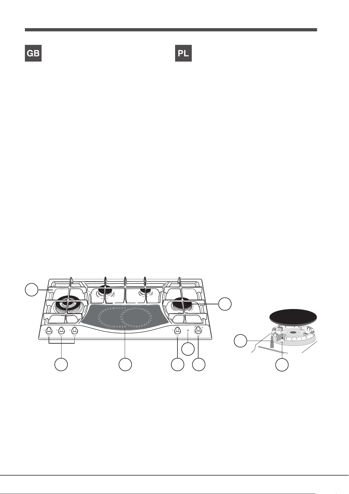
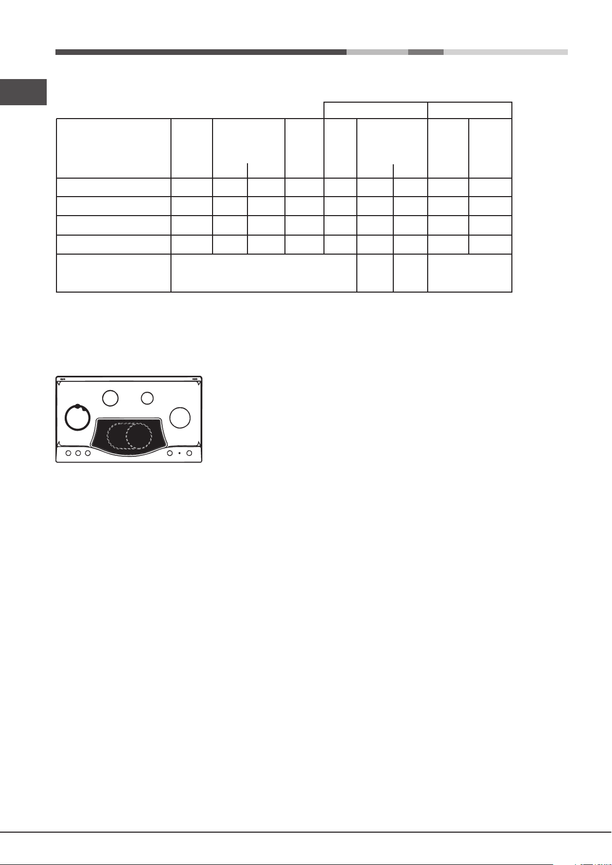
Overall view
1. Support Grid for COOKWARE
2. GAS BURNERS
3. Control Knobs for CERAMIC GLASS MODULE
4. Control Knobs for GAS BURNERS
5. INDICATOR LIGHT for CERAMIC GLASS MODULE
6. CERAMIC GLASS MODULE
7. Ignition for GAS BURNERS
8. SAFETY DEVICES
• The INDICATOR LIGHT for CERAMIC GLASS MODULE switches on
whenever the selector knob is moved from the ‘off’ position.
• Control Knobs for GAS BURNERS and CERAMIC GLASS MODULE
adjust the power or the size of the ame.
• GAS BURNERS differ in size and power. Use the diameter of the cookware
to choose the most appropriate burner to cook with.
• GAS BURNER IGNITION enables a specic burner to be lit automatically.
• SAFETY DEVICE stops the gas flow if the flame is accidentally
extinguished.
Widok ogólny
1. Ruszty do ustawiania NACZYŃ DO GOTOWANIA
2. PALNIKI GAZOWE
3. Pokrętła sterujące PŁYTY CERAMICZNEJ
4. Pokrętła sterujące PALNIKÓW GAZOWYCH
5. Kontrolka działania PŁYTY CERAMICZNEJ
6. PŁYTA CERAMICZNA
7. Świeca zapłonowa PALNIKÓW GAZOWYCH
8. URZĄDZENIA ZABEZPIECZAJĄCE
• Kontrolka działania PŁYTY CERAMICZNEJ zapala się dla każdej pozycji
pokrętła z wyjątkiem pozycji wyłączenia.
• Pokrętła sterowania PALNIKAMI GAZOWYMI oraz PŁYTĄ CERAMICZĄ
do regulowania płomienia lub mocy.
• PALNIKI GAZOWE posiadają różne wymiary i moce. Należy wybrać ten
palnik, który jest najbardziej odpowiedni dla średnicy używanego naczynia.
• Świeca zapłonowa PALNIKÓW GAZOWYCH umożliwia automatyczne
zapalenie wybranego palnika.
• URZĄDZENIE ZABEZPIECZAJĄCE w razie przypadkowego zgaśnięcia
płomienia przerywa dopływ gazu.
4
3
7
5
Page 6
A készülék leírása
8
1
2
655
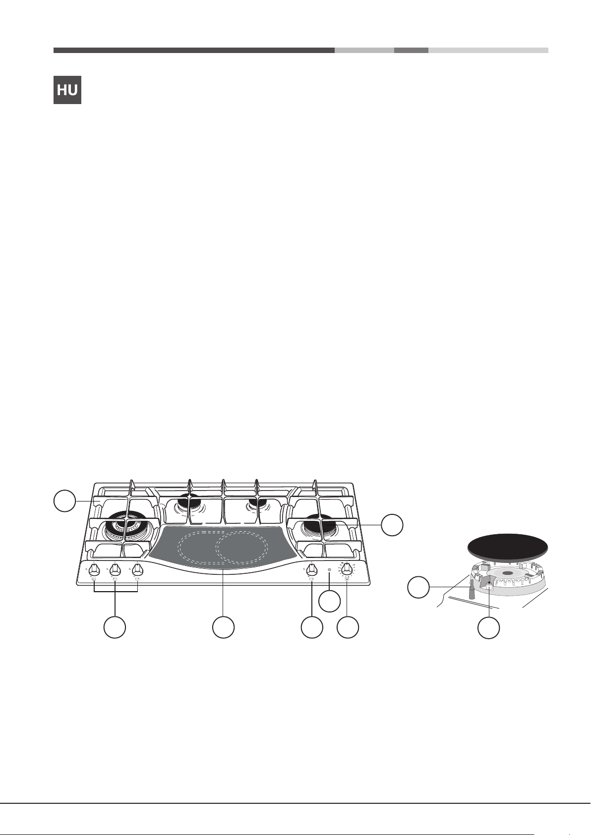
A készülék áttekintése
1. Tartórács FŐZŐEDÉNYEKHEZ
2. GÁZÉGŐK
3. A ÜVEGKERÁMIA MODUL szabályzógombjai
4. A GÁZÉGŐK szabályzógombjai
5. A ÜVEGKERÁMIA MODUL VISSZAJELZŐ LÁMPÁI
6. ÜVEGKERÁMIA MODUL
7. Gyújtó a GÁZÉGŐKHÖZ
8. BIZTONSÁGI ESZKÖZÖK
• A ÜVEGKERÁMIA MODUL VISSZAJELZŐ LÁMPÁJA világítani kezd,
ha a választókapcsolót elmozdítja „off” (ki) állásból.
• A GÁZÉGŐKés a ÜVEGKERÁMIA MODUL szabályzógombjaival
állíthatja be a teljesítményt vagy a láng nagyságát.
• A GÁZÉGŐK mérete és teljesítménye eltérő. A főzőedény átmérője alapján
válassza ki a főzéshez leginkább megfelelő gázégőt
• A GÁZÉGŐ GYÚJTÓJA segítségével egy adott égőt gyújthat be
automatikusan.
• A BIZTONSÁGI ESZKÖZ megállítja a gáz áramlását, ha a láng véletlenül
kialszik.
4
3
6
7
Page 7
Installation
! Before operating your new appliance please read this instruction booklet
carefully. It contains important information for safe use, installation and care
of the appliance.
! Please keep these operating instructions for future reference. Pass them on
to possible new owners of the appliance.
Positioning
! Keep packaging material out of the reach of children. It can become a choking
or suffocation hazard (see Precautions and tips).
! The appliance must be installed by a qualied professional according to the
instructions provided. Incorrect installation may cause harm to people and
animals or may damage property.
! This unit may be installed and used only in permanently ventilated rooms
in accordance with current national regulations. The following requirements
must be observed:
• The room must be equipped with an air extraction system that expels
any combustion fumes. This may consist of a hood or an electric fan that
automatically starts each time the appliance is switched on.
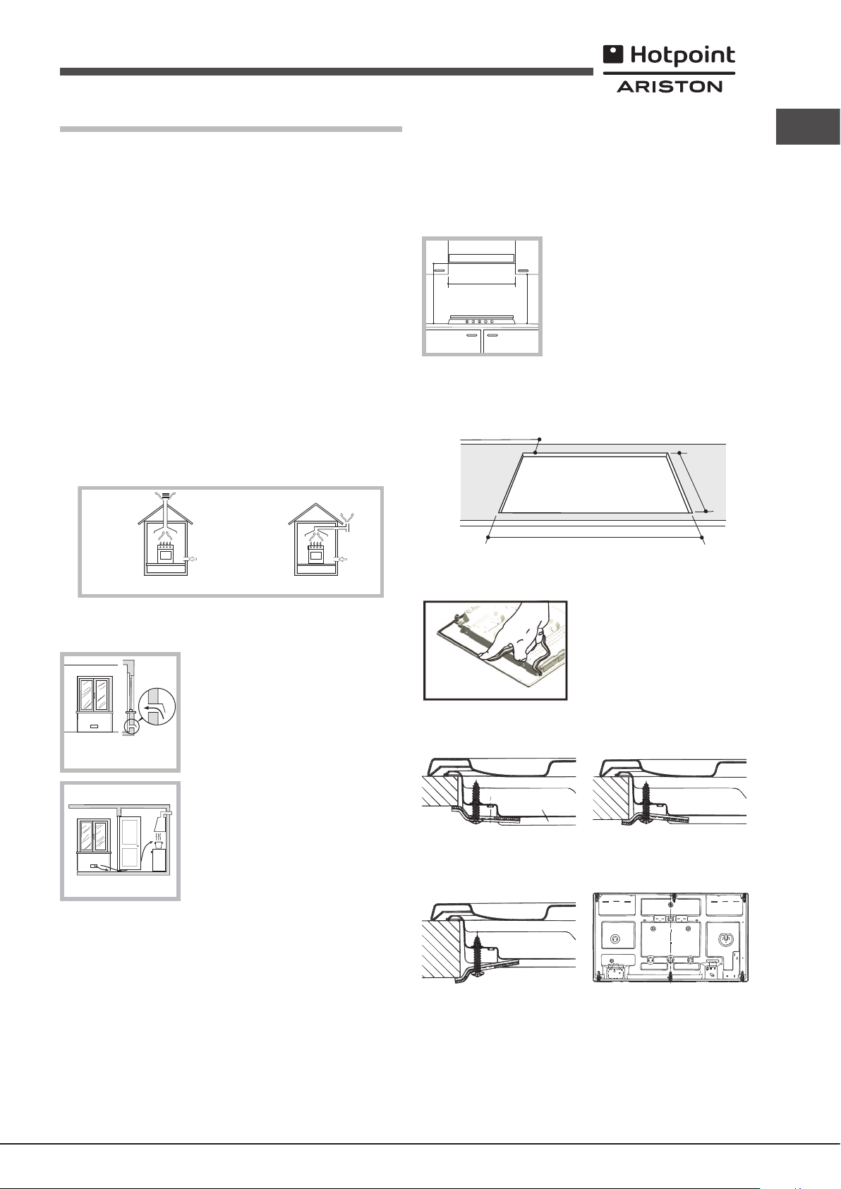
Fitting the appliance
The following precautions must be taken when installing the hob:
• Kitchen cabinets adjacent to the appliance and taller than the top of the
hob must be at least 200 mm from the edge of the hob.
• Hoods must be installed according to their relative installation instruction
manuals and at a minimum distance of 650 mm from the hob (see gure).
• Place the wall cabinets adjacent to the hood at a minimum height of 420
mm from the hob (see gure).
If the hob is installed beneath a wall cabinet,
the latter must be situated at a minimum of 700
600mm min.
650mm min.
mm above the hob.
420mm min.
• The installation cavity should have the dimensions indicated in the gure.
Fastening hooks are provided, allowing you to fasten the hob to tops that
are between 20 and 40 mm thick. To ensure the hob is securely fastened
to the top, we recommend you use all the hooks provided.
min. 55 mm.
475 mm.
GB
In a chimney stack or branched flue.
(exclusively for cooking appliances)
Directly to
the Outside
• The room must also allow proper air circulation, as air is needed for
combustion to occur normally. The ow of air must not be less than 2 m3/h
per kW of installed power.
The air circulation system may take air directly
from the outside by means of a pipe with an
inner cross section of at least 100 cm2; the
opening must not be vulnerable to any type
Examples of
ventilation holes
for comburant air.
Adjacent
Room
A
Room to be
Vented
of blockages.
The system can also provide the air needed for
combustion indirectly, i.e. from adjacent rooms
tted with air circulation tubes as described
above. However, these rooms must not be
communal rooms, bedrooms or rooms that
may present a re hazard.
Enlarging the ventilation slot
between window and floor.
• Intensive and prolonged use of the appliance may necessitate
supplemental ventilation, e.g. opening a window or increasing the power
of the air intake system (if present).
• Liquid petroleum gas sinks to the oor as it is heavier than air. Therefore,
rooms containing LPG cylinders must also be equipped with vents to allow
gas to escape in the event of a leak. As a result LPG cylinders, whether
partially or completely full, must not be installed or stored in rooms or
storage areas that are below ground level (cellars, etc.). It is advisable to
keep only the cylinder being used in the room, positioned so that it is not
subject to heat produced by external sources (ovens, replaces, stoves,
etc. ) which could raise the temperature of the cylinder above 50°C.
835 mm.
Before the installation remove the grids and burners from the hob and turn it
upside down, making sure you don’t damage the thermocouples and spark
plugs.
Apply the seals that come with the
appliance along the outer edges of
the hob to prevent any passage of air,
humidity and water (see Figure).
For proper application make sure the
surfaces to be sealed are clean, dry and
free of any grease/oil.
Hook fastening diagram
Hooking position for top H=20mm Hooking position for top H=30mm
Front
Hooking position for top H=40mm Back
! Use the hooks contained in the “accessory pack”.
• Where the hob is not installed over a built-in oven, a wooden panel must
be installed as insulation. This must be placed at a minimum distance of
20 mm from the lower part of the hob.
7
Page 8
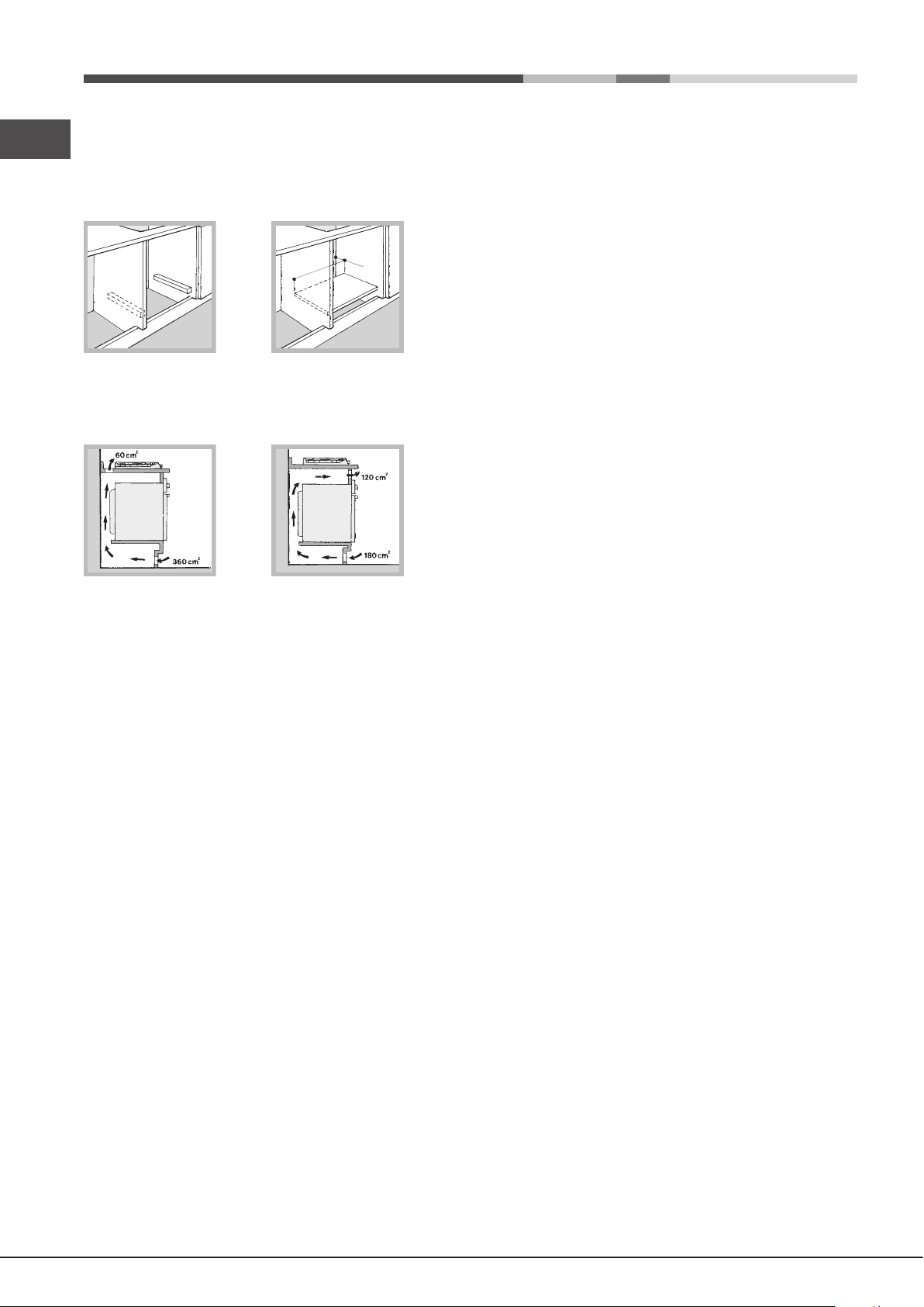
Ventilation
GB
To ensure adequate ventilation, the back panel of the cabinet must be
removed. It is advisable to install the oven so that it rests on two strips of
wood, or on a completely at surface with an opening of at least 45 x 560
mm (see diagrams).
45 mm.
560 mm.
Where a hob is installed above an oven without a forced ventilation cooling
system, adequate ventilation must be provided inside the cabinet by means
of air holes through which air can pass (see gure).
Electrical connection
Hobs equipped with a three-pole power supply cable are designed to operate
with alternating current at the voltage and frequency indicated on the data
plate (this is located on the lower part of the appliance). The earth wire in the
cable has a green and yellow cover. If the appliance is to be installed above
a built-in electric oven, the electrical connection of the hob and the oven must
be carried out separately, both for electrical safety purposes and to make
extracting the oven easier.
Connecting the supply cable to the mains
Install a standardised plug corresponding to the load indicated on the data
plate.
The appliance must be directly connected to the mains using an omnipolar
circuit-breaker with a minimum contact opening of 3 mm installed between the
appliance and the mains. The circuit-breaker must be suitable for the charge
indicated and must comply with current electrical regulations (the earthing
wire must not be interrupted by the circuit-breaker). The supply cable must
not come into contact with surfaces with temperatures higher than 50°C.
! The installer must ensure that the correct electrical connection has been
made and that it is compliant with safety regulations.
Before connecting to the power supply, make sure that:
• the appliance is earthed and the plug is compliant with the law.
• the socket can withstand the maximum power of the appliance, which is
indicated on the data plate.
• the voltage is in the range between the values indicated on the data plate.
• the socket is compatible with the plug of the appliance. If the socket is
incompatible with the plug, ask an authorised technician to replace it. Do
not use extension cords or multiple sockets.
! Once the appliance has been installed, the power supply cable and the
electrical socket must be easily accessible.
! The cable must not be bent or compressed.
! The cable must be checked regularly and replaced by authorised technicians
only (see Assistance).
! The manufacturer declines any liability should these safety measures not
be observed.
Gas connection
The appliance should be connected to the main gas supply or to a gas
cylinder in compliance with current national regulations. Before carrying out
the connection, make sure the cooker is compatible with the gas supply you
wish to use. If this is not the case, follow the instructions indicated in the
paragraph “Adapting to different types of gas.”
When using liquid gas from a cylinder, install a pressure regulator which
complies with current national regulations.
! Check that the pressure of the gas supply is consistent with the values
indicated in Table 1 (“Burner and nozzle specications”). This will ensure the
safe operation and longevity of your appliance while maintaining efcient
energy consumption.
Connection with a rigid pipe (copper or steel)
! Connection to the gas system must be carried out in such a way as not to
place any strain of any kind on the appliance.
There is an adjustable L-shaped pipe tting on the appliance supply ramp
and this is tted with a seal in order to prevent leaks. The seal must always
be replaced after rotating the pipe tting (seal provided with appliance). The
gas supply pipe tting is a threaded 1/2 gas cylindrical male attachment.
Connecting a flexible jointless stainless steel pipe to a threaded
attachment
The gas supply pipe tting is a threaded 1/2 gas cylindrical male attachment.
These pipes must be installed so that they are never longer than 2000 mm
when fully extended. Once connection has been carried out, make sure that
the exible metal pipe does not touch any moving parts and is not compressed.
! Only use pipes and seals that comply with current national regulations.
Checking the tightness of the connection
! When the installation process is complete, check the pipe ttings for leaks
using a soapy solution. Never use a ame.
Adapting to different types of gas
To adapt the hob to a different type of gas other than default type (indicated
on the rating plate at the base of the hob or on the packaging), the burner
nozzles should be replaced as follows:
1. Remove the hob grids and slide the burners off their seats.
2. Unscrew the nozzles using a 7 mm socket spanner, and replace them
with nozzles for the new type of gas (see table 1 “Burner and nozzle
characteristics”).
3. Reassemble the parts following the above procedure in the reverse order.
4. Once this procedure is nished, replace the old rating sticker with one
indicating the new type of gas used. Sticker are available from any of our
Service Centres.
• Adjusting the burners’ primary air
Does not require adjusting.
8
Page 9
• Setting the burners to minimum
1. Turn the tap to the low ame position;
2. Remove the knob and adjust the adjustment
screw, which is positioned in or next to the tap
pin, until the ame is small but steady.
3. Having adjusted the ame to the required low setting, while the burner is
alight, quickly change the position of the knob from minimum to maximum
and vice versa several times, checking that the ame does not go out.
4. Some appliances have a safety device (thermocouple) tted. If the device
fails to work when the burners are set to the low ame setting, increase
this low ame setting using the adjusting screw.
5. Once the adjustment has been made, replace the seals on the by-passes
using sealing wax or a similar substance.
! If the appliance is connected to liquid gas, the regulation screw must be
fastened as tightly as possible.
! Once this procedure is nished, replace the old rating sticker with one
indicating the new type of gas used. Stickers are available from any of our
Service Centres.
GB
! Should the gas pressure used be different (or vary slightly) from the
recommended pressure, a suitable pressure regulator must be tted to the
inlet pipe (in order to comply with current national regulations).
DATA PLATE
Electrical
connections
ECODESIGN
see data plate
This appliance conforms to the following
European Economic Community directives:
- 2006/95/EC dated 12/12/06 (Low Voltage)
and subsequent amendments
- 2004/108/EC dated 15/12/04
(Electromagnetic Compatibility) and
subsequent amendments
- 93/68/EEC dated 22/07/93 and subsequent
amendments.
- 2009/142/EC dated 30/11/06 (Gas) and
subsequent amendments
- 2012/19/EU and subsequent amendments.
EU Regulation no. 66/2014 implementing
Directive 2009/125/EC.
standard EN 60350-2
standard EN 30-2-1
9
Page 10
*
**
***
Burner and nozzle specifications
GB
Table 1 Liquid Gas Natural Gas
Burner
Diameter
(mm)
Thermal Power
kW (p.c.s.*)
By-pass
1/100
(mm)
Nozzle
1/100
(mm)
Flow*
g/h
Nozzle
1/100
(mm)
Flow*
l/h
Reduced Rapid (RR)
Semi Rapid (S)
Auxiliary (A)
Triple Crown (TC)
Supply
pressures
At 15°C and 1013,25 mbar - dry gas
Propane (G31) P. C.S. = 50.37 MJ/Kg
Butane (G30) P. C.S. = 49.47 MJ/Kg
Natural (G20) P.C.S. = 37.78 MJ/m³
S
TC
Nominal Reduced
100
75
55
130
2.60
1.65
1.00
3.25
0.70
0.40
0.40
1.50
39
28
28
61
80
64
50
91
Nominal (mbar)
Minimum (mbar)
Maximum (mbar)
A
RR
***
189
120
73
236
28-30
20
35
**
186
118
71
232
37
25
45
110(Y)
96(Z)
71(Y)
133(Z)
248
157
95
309
20
17
25
PH 941 MSTV GH/HA EE
10
Page 11
Start-up and use
A
C
B
! The position of the corresponding gas burner or electric hotplate is shown
on every knob.
Gas burners
Each burner can be adjusted to one of the following settings using the
corresponding control knob:
● Off
Maximum
Minimum
To light one of the burners, hold a lit match or lighter near the burner and, at
the same time, press down and turn the corresponding knob anti-clockwise
to the maximum setting.
Since the burner is tted with a safety device, the knob should be pressed
for approximately 2-3 seconds to allow the automatic device keeping the
ame alight to heat up.
When using models with an ignition button, light the desired burner pressing
down the corresponding knob as far as possible and turning it anticlockwise
towards the maximum setting.
! If a ame is accidentally extinguished, turn off the control knob and wait for
at least 1 minute before trying to relight it.
To switch off the burner, turn the knob in a clockwise direction until it stops
(when reaches the “●” position).
GB
When the knob is on any of the settings other than “Off”, the Indicator Light
for Ceramic Glass Module comes on.
Practical Advise on Using the Ceramic Glass Module
Set.
10
11
12
Radiant Burner
0
Off.
1
To melt butter and chocolate.
2
To heat liquids.
3
4
For creams and sauces.
5
6
For cooking at the boiling point.
7
8
For Roasts.
9
For boiling large pieces of meat.
For frying.
For utilising both cooking areas.
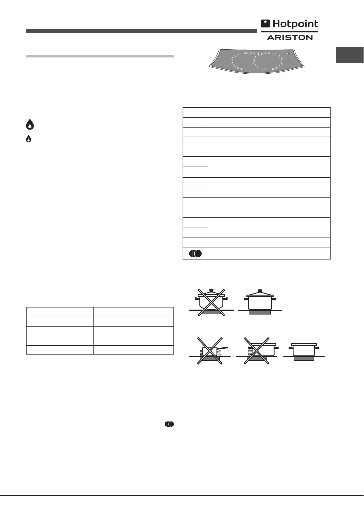
Practical advice on using the burners
To ensure the burners operate efciently:
• Use appropriate cookware for each burner (see table) so that the ames
To obtain the best results from your hob:
• Use at-bottomed pans to ensure that they adhere to the cooking zone
perfectly.
do not extend beyond the bottom of the cookware.
• Always use cookware with a at base and a cover.
• When the contents of the pan reach boiling point, turn the knob to minimum.
Burner
Reduced Rapid (RR)
Semi Rapid (S)
Auxiliary (A)
Triple Crown (TC)
To identify the type of burner, refer to the designs in the section entitled, “Burner
and Nozzle Specications”.
Ceramic Glass Module
This cooktop is tted with dual-ring radiant heating elements located beneath
the glass. It is possible to turn on only the circular part of the elemement
(identied by the letter “A”) or the cooking surface can be enlarged by turning
on both “A” and “B”. To turn only the circular “A” element, simply turn the
knob in the clockwise direction to any one of the 12 available settings. To add
the “B” section, turn the knob to setting 12 and then click it into the
setting. Then proceed by turning the knob in the counter-clockwise direction
to one of the 12 settings.
The gure shows the heating zones, which become red when the element
is turned on.
A. Circular heating zone;
B. Extended heating zone;
Ø Cookware diameter (cm)
24 - 26
16 - 20
10 - 14
24 - 26
• Always use pans with a diameter that is large enough to cover the hotplate
fully, in order to use all the available heat.
• Make sure that the bottom of the cookware is always dry and clean to
guarantee correct adherence and long life, not only for the cooking zones
but also for the cookware itself.
• Avoid using the same cookware that is used on gas burners: the heat
concentration on gas burners may deform the base of the pan, causing it
not to adhere correctly.
• Never leave a cooking zone on without cookware on it because as it
heats up and rapidly reaches the maximum level, which could damage
the heating elements.
! There might be traces of grease left by the glue used to seal the glass
which should be removed before using the appliance with a mild cleaning
product. During the rst few hours of use you might smell rubber but this will
disappear quickly.
C. Indicator light to show when the cooking zone is above 60°C, even after
the heating element has been turned off.
11
Page 12

Precautions and tips
GB
! This appliance has been designed and manufactured in compliance with
international safety standards. The following warnings are provided for safety
reasons and must be read carefully.
and recycling of the materials they contain and reduce the impact on
human health and the environment.The crossed out “wheeled bin” symbol
on the product reminds you of your obligation, that when you dispose of
the appliance it must be separately collected.
Consumers should contact their local authority or retailer for information
concerning the correct disposal of their old appliance.
General safety
• This is a class 3 built-in appliance.
• Gas appliances require regular air exchange to maintain efcient
operation. When installing the hob, follow the instructions provided
in the paragraph on “Positioning” the appliance.
• These instructions are only valid for the countries whose symbols
appear in the manual and on the serial number plate.
• The appliance was designed for domestic use inside the home and is not
intended for commercial or industrial use.
• The appliance must not be installed outdoors, even in covered areas. It is
extremely dangerous to leave the appliance exposed to rain and storms.
• Do not touch the appliance with bare feet or with wet or damp hands and
feet.
• The appliance must be used by adults only for the preparation of food,
in accordance with the instructions outlined in this booklet. Any other
use of the appliance (e.g. for heating the room) constitutes improper
use and is dangerous. The manufacturer may not be held liable for
any damage resulting from improper, incorrect and unreasonable
use of the appliance.
• Ensure that the power supply cables of other electrical appliances do not
come into contact with the hot parts of the oven.
• The openings used for ventilation and dispersion of heat must never be
covered.
• Always make sure the knobs are in the “●”/“○” position when the appliance
is not in use.
• When unplugging the appliance always pull the plug from the mains socket,
do not pull on the cable.
• Never carry out any cleaning or maintenance work without having detached
the plug from the mains.
• In case of malfunction, under no circumstances should you attempt to repair
the appliance yourself. Repairs carried out by inexperienced persons may
cause injury or further malfunctioning of the appliance. Contact a Service
Centre (see Assistance).
• Always make sure that pan handles are turned towards the centre of the
hob in order to avoid accidental burns.
• Do not close the glass cover (if present) when the gas burners or electric
hotplates are still hot.
• Do not leave the electric hotplate switched on without a pan placed on it.
• Do not use unstable or deformed pans.
• The appliance should not be operated by people (including children)
with reduced physical, sensory or mental capacities, by inexperienced
individuals or by anyone who is not familiar with the product. These
individuals should, at the very least, be supervised by someone who
assumes responsibility for their safety or receive preliminary instructions
relating to the operation of the appliance.
• Do not let children play with the appliance.
• The appliance is not intended to be operated by means of an external
timer or separate remote-control system.
Disposal
• When disposing of packaging material: observe local legislation so that
the packaging may be reused.
• The European Directive 2012/19/EU on Waste Electrical and Electronic
Equipment (WEEE), requires that old household electrical appliances must
not be disposed of in the normal unsorted municipal waste stream. Old
appliances must be collected separately in order to optimise the recovery
Respecting and conserving the environment
• Make the most of your hot plate’s residual heat by switching off cast iron hot
plates 10 minutes before the end of your cooking time and glass ceramic
hot plates 5 minutes before the end of cooking time.
• The base of your pot or pan should cover the hot plate. If it is smaller,
precious energy will be wasted and pots that boil over leave encrusted
remains that can be difcult to remove.
• Cook your food in closed pots or pans with well-tting lids and use as little
water as possible. Cooking with the lid off will greatly increase energy
consumption.
• Use purely at pots and pans.
• If you are cooking something that takes a long time, it’s worth using a
pressure cooker, which is twice as fast and saves a third of the energy.
Maintenance and care
Switching the appliance off
Disconnect your appliance from the electricity supply before carrying out
any work on it.
Cleaning the appliance
! Do not use abrasive or corrosive detergents such as stain removers, anti-rust
products, powder detergents or sponges with abrasive surfaces: these may
scratch the surface beyond repair.
! Never use steam cleaners or pressure cleaners on the appliance.
• It is usually enough to wash the hob with a damp sponge and dry it with
absorbent kitchen roll.
• The removable parts of the burners should be washed frequently with
warm water and soap and any burnt-on substances removed.
• For hobs which ligth automatically, the terminal part of the electronic instant
lighting devices should be cleaned frequently and the gas outlet holes
should be checked for blockages.
• Before using the ceramic glass module, the surface must be cleaned,
using a damp cloth to remove dust or food residues. The ceramic glass
surface should be cleaned regularly with a soultion of warm water and a
non-abrasive detergent.
• Stainless steel can be marked by hard water that has been left on the
surface for a long time, or by aggressive detergents containing phosphorus.
After cleaning, rinse and dry any remaining drops of water.
Periodically, special products will need to
be used to clean the surface. First, remove
all food buildup or grease with a cleaning
scraper, e.g. (not supplied).
Clean the cooking surface when it is still
warm with a suitable cleaning product
(such as the one in the Solutions product
line available from any After-Sales Service
Centre) and paper towels. Then rub with a damp cloth and dry. Aluminum
foil, plastic items, objects made of synthetic material, sugar or foods with
a high sugar content that have melted onto the surface must be removed
immediatley with a scraper while the cooking surface is still hot.
12
Page 13

Special cleaning products for ceramic glass
surfaces form a transparent protective
layer which ghts diry buildup. This also
protects the surface from damage caused
by food with a high sugar content. Do not
use abrasive sponges or cleaning products
under any circumstances. This holds true
for chemically aggressive cleaners, like
oven sprays and stain removers.
Gas tap maintenance
Over time, the taps may become jammed or difcult to turn. If this happens,
the tap must be replaced.
! This procedure must be performed by a qualied technician authorised
by the manufacturer.
Troubleshooting
It may happen that the appliance does not function properly or at all. Before
calling the service centre for assistance, check if anything can be done. First,
check to see that there are no interruptions in the gas and electrical supplies,
and, in particular, that the gas valves for the mains are open.
GB
The burner does not light or the ame is not even around the burner.
Check whether:
• The gas holes on the burner are clogged.
• All the movable parts that make up the burner are mounted correctly.
• There are draughts near the appliance.
The ame dies in models with a safety device.
Check to make sure that:
• You pressed the knob all the way in.
• You keep the knob pressed in long enough to activate the safety device.
• The gas holes are not blocked in the area corresponding to the safety
device.
The burner does not remain lit when set to minimum.
Check to make sure that:
• The gas holes are not blocked.
• There are no draughts near the appliance.
• The minimum setting has been adjusted properly.
The cookware is unstable.
Check to make sure that:
• The bottom of the cookware is perfectly at.
• The cookware is positioned correctly at the centre of the burner.
• The pan support grids have been positioned correctly.
13
Page 14

min. 55 mm.
Instalacja
PL
! Ważnym jest, aby zachować niniejszą instrukcję dla przyszłych konsultacji.
W razie sprzedaży, odsprzedania, czy przeniesienia, należy upewnić się,
czy znajduje się ona wraz z urządzeniem i odpowiednimi uwagami, aby
poinformować nowego właściciela o jego funkcjonowaniu.
! Należy uważnie przeczytać instrukcję: zawieraja ona ważne informacje
dotyczące instalacji, użytkowania i bezpieczeństwa.
Ustawienie
! Opakowania nie są zabawkami dla dzieci i należy je usunąć zgodnie z
normami zbierania odpadów (patrz Środki ostrożności i zalecenia).
! Instalacja powinna zostać wykonana zgodnie z niniejszymi instrukcjami i
przez personel zawodowo do tego przygotowany. Błędna instalacja może
skutkować powstaniem szkód wobec osób, zwierząt lub rzeczy.
! Niniejsze urządzenie może zostać zainstalowane wyłącznie w
pomieszczeniach ze stałą wentylacją, zgodnie z zaleceniami obowiązujących
norm krajowych. Należy dochować następujących warunków:
• Pomieszczenie powinno posiadać system odprowadzający na zewnątrz
gazów spalinowych składający się z okapu lub wyciągu elektrycznego,
uruchamianego automatycznie każdorazowo podczas uruchomienia
urządzenia.
W kominie lub w odgałęzionym przewodzie dymnym
(przeznaczonym dla urządzeń kuchennych)
• Pomieszczenie powinno posiadać funkcjonalny system dopływu
powietrza umożliwiający normalne spalanie. Dopływ niezbędnego do
spalania powietrza nie powinien być mniejszy niż 2 m3/h na każdy kW
zainstalowanej mocy.
System może polegać na bezpośrednim
poborze powietrza z zewnątrz budynku przy
pomocy kanału o przekroju użytecznym
przynajmniej 100 cm2 i zabezpieczonego przed
A
Przykłady otwarcia
wentylacji
dla powietrza do spalania
Pomieszczenie
przyległe
Pomieszczenie
przeznaczone
do przewietrzania
przypadkowym zaślepieniem.
Albo też, w sposób pośredni, z przyległych
pomieszczeń wyposażonych w przewód
wentylacyjny jak opisany powyżej, a nie będący
częścią wspólną dla całej nieruchomości
ani nie mający połączeń z pomieszczeniami
sypialni lub w których występuje zagrożenie
Zwiększenie szczeliny pomiędzy
drzwiami a podłogą
pożarem.
• Intensywne i długotrwałe stosowanie urządzenia może wymagać
dodatkowej wentylacji, na przykład otwarcia okna lub bardziej skutecznej
wentylacji, zwiększającej mechaniczną siłę ssania (jeśli już istnieje).
• Skroplone gazy pochodne ropy naftowej, cięższe od powietrza, opadają
w dół. Dlatego pomieszczenia, w których przechowywane są butle GPL
powinny przewidywać otwory prowadzące na zewnątrz umożliwiające
spływanie ku dołowi ewentualnych wycieków gazu. Ponadto butle
GPL, niezaleznże od tego czy są puste, czy częściowo napełnione,
Bezpośrednio
na zewnątrz
nie powinny być instalowane ani składowane w pomieszczeniach lub
komorach o położonych poniżej poziomu podłogi (piwnice, itp.). Dobrze
jest przechowywać w pomieszczeniu jedynie butle aktualnie użytkowaną,
umocowaną w sposób nie narażający jej na bezpośrednie oddziaływanie
źródeł ciepła (piece, kominki, piecyki, itp.) mogące doprowadzić do wzrostu
temperatury powietrza powyżej 50°C.
Zabudowa
W celu poprawnego zainstalowania płyty grzewczej należy zachować
następujące środki ostrożności:
• Meble znajdujące się obok, a których wysokość przekracza wysokość
płyty roboczej, powinny zostać odsunięte przynajmniej na 200 mm od
krawędzi płyty roboczej.
• Okapy powinny być zainstalowane zgodnie z warunkami wymaganymi
podanymi przez instrukcje samych okapów, jednak w minimalnej odległości
650 mm (patrz ilustracja).
• Umieścić sąsiadujące z okapem szafki wiszące na wysokości minimalne
od szczytu 420 mm (patrz ilustracja).
By płyta grzewcza mogła być zainstalowana
pod szafką wiszącą, ta ostatnia powinna
600mm min.
znajdować się w odległości minimalnej od
szczytu wynoszącej 700 mm.
650mm min.
420mm min.
• Wnęka na obudowę powinna mieć wymiary podane na ilustracji.
Przewidziano uchwyty mocujące umożliwiające zamocowanie płyty na
podstawie posiadającej grubość od 20 do 40 mm. Aby solidnie zamocować
płytę zaleca się zastosowanie wszystkich uchwytów znajdujących się do
dyspozycji.
475 mm.
835 mm.
Przed zainstalowaniem płyty kuchennej, należy zdjąć ruszty i palniki i odwrócić
ją częścią spodnią do góry, uważając na to, aby nie uszkodzić termopar i
świec zapłonowych.
Następnie należy założyć uszczelki
dostarczone na wyposażeniu na
zewnętrzne krawędzie płyty kuchennej,
aby uniemożliwić przedostawanie się
powietrza, wilgoci i wody (zob. rysunek).
Aby wykonać powyższą czynność
prawidłowo, należy upewnić się, że
uszczelniane powierzchnie są czyste, suche i nie są zabrudzone smarami/
olejami.
Schemat mocowania uchwytów
Położenie uchwytu w stosunku Położenie uchwytu w stosunku
do blatu H=20mm stosunku do blatu H=30mm
14
Page 15

Przód
Położenie uchwytu w stosunku Tył
do blatu H=40mm
! Stosować uchwyty zawarte w „zestawie akcesoriów”
• W przypadku, gdy płyta nie jest zainstalowana na zabudowanym
piekarniku, koniecznym jest zastosowanie płyty drewnianej jako izolatora.
Powinna być ona zamocowana w odległości minimum 20 mm od dolnej
części samej płyty roboczej.
! Instalator odpowiada za poprawność podłączenia elektrycznego i za
zachowanie norm bezpieczeństwa.
Przed wykonaniem podłączenia należy upewnić się, czy:
• gniazdko posiada odpowiednie uziemienie i zgodne jest z obowiązującymi
przepisami;
• gniazdko jest w stanie wytrzymać obciążenie maksymalnej mocy
urządzenia wskazane na tabliczce znamionowej;
• napięcie zasilania odpowiada wartościom podanym na tabliczce
znamionowej;
• gniazdko musi być odpowiednie dla wtyczki urządzenia. W przeciwnym
razie należy wymienić gniazdko lub wtyczkę; nie stosować przedłużaczy,
ani rozgałęźników.
! Po zainstalowaniu urządzenia przewód elektryczny i gniazdko powinny być
łatwo dostępne.
PL
Obieg powietrza
W celu zapewnienia dobrego obiegu powietrza koniecznym jest usunięcie
tylnej ścianki komory. Najlepiej zainstalować piekarnik w taki sposób, aby
wspierał się na dwóch listwach drewnianych lub na drewnianej desce z
prześwitem przynajmniej 45 x 560 mm (patrz ilustracje).
45 mm.
560 mm.
W przypadku instalacji na piekarniku nie wyposażonym w obieg chłodzący
należy zapewnić swobodny przepływ powietrza w celu właściwej wentylacji.
Podłączenie do sieci elektrycznej
Płyty wyposażone w przewód zasilający trójżyłowy dostosowane są do
pracy na prąd zmienny przy napięciu i częstotliwości zasilania wskazanych
na tabliczce znamionowej (umieszczonej w dolnej części płyty). Przewód
uziemienia w sznurze oznaczony jest kolorem żółto-zielonym. W
przypadku zainstalowania ponad piekarnikiem zabudowanym podłączenia
elektryczne płyty i piekarnika powinny być wykonane osobno, tak z przyczyn
bezpieczeństwa elektrycznego, jak i dla ułatwienia ewentualnego wyjęcia
piekarnika.
Podłączenie przewodu zasilającego do sieci
Zamocować na przewodzie znormalizowaną wtyczkę do obciążeń
wskazanych na tabliczce znamionowej.
W przypadku bezpośredniego podłączenia do sieci koniecznym jest
zainstalowanie pomiędzy urządzeniem a siecią wyłącznika polowego z
otwarciem minimalnym pomiędzy stykami 3 mm przeznaczonego do obciążeń
i odpowiadającego obowiązującym normom (przewód uziemienia nie
powinien być przerywany przez wyłącznik). Przewód zasilania powinien być
umieszczony w taki sposób, aby w żadnym punkcie temperatura otoczenia
nie przekraczała 50°C.
! Kabla nie wolno zginać ani przyciskać.
! Przewód elektryczny musi być okresowo sprawdzany i wymieniany jedynie
przez autoryzowanych techników (patrz Serwis).
! Producent odrzuca wszelką odpowiedzialność w przypadku, gdy niniejsze
zasady nie będą przestrzegane.
Podłączenie gazu
Podłączenie urządzenia do przewodów lub butli gazowej powinno zostać
wykonane zgodnie z zaleceniami obowiązujących norm krajowych dopiero po
upewnieniu się, że jest ono wyregulowane do pracy z rodzajem gazu, którym
będzie zasilane. W przeciwnym wypadku wykonać czynności wskazane w
paragrae “Dostosowanie do różnych rodzajów gazu” W przypadku zasilania
płynnym gazem z butli, stosować regulatory ciśnienia zgodne z obowiązującymi
normami krajowymi.
! W celu uzyskania pewności pracy, odpowiedniego zużycia energii i
zwiększenia trwałości urządzenia należy upewnić się czy ciśnienie zasilania
mieści się w granicach zalecanych w tabeli 1 „Charakterystyki palników i
dysz”.
Podłączenie przewodem sztywnym (miedź lub stal)
! Podłączenie do urządzenia gazowego powinno być wykonane w taki sposób,
aby nie powodować żądnych naprężeń urządzenia.
Na przewodzie zasilającym urządzenie znajduje się ruchome złącze
kolankowe “L” , którego szczelność zapewniona jest uszczelką. W przypadku
gdyby okazało się, że koniecznym jest obrócenie kolanka należy obowiązkowo
wymienić uszczelkę (na wyposażeniu urządzenia). Złącze wejściowe gazu
do urządzenia jest gwintowane gwintem gazowym 1/2 walcowym męskim.
Podłączenie z przewodem elastycznym ze stali nierdzewnej o pełnych
ściankach z gwintowanymi złączami.
Złącze wejściowe gazu do urządzenia jest gwintowane gwintem gazowym
1/2 walcowym męskim.
Użycie przewodów tego rodzaju powinno być wykonane w ten sposób, aby
ich długość, w warunkach maksymalnego rozszerzenia nie przekraczała
2000 mm. Po wykonaniu podłaczenia upewnic się, czy metalowy przewód
elastyczny nie styka się z elementami ruchomymi, ani nie jest przygnieciony.
! Stosować wyłącznie przewody i uszczelki zgodne z obowiązującymi normami
krajowymi.
Kontrola szczelności
! Po zakończeniu instalacji skontrolować szczelność wszystkich złącz stosując
w tym celu wodny rozwór mydła, nigdy płomień.
15
Page 16

Dostosowanie do różnych rodzajów gazu
Niniejsze urządzenie zostało wyprodukowane
zgodnie z następującymi dyrektywami unijnymi:
- 2006/95/WE z 12/12/06 (o Niskim Napięciu)
wraz z późniejszymi zmianami
- 2004/108/WE z 15/12/04 (o Zgodności
Elektromagnetycznej) wraz z późniejszymi
zmianami
- 93/68/EWG z 22/07/93 wraz z późniejszymi
zmianami
- 2009/142/WE z 30/11/09 (Gaz) wraz z
późniejszymi zmianami
- 2012/19/UE wraz z późniejszymi zmianami
Rozporządzenie UE nr 66/2014,
integrujące dyrektywę 2009/125/KE
Rozporządzenie EN 60350-2
Rozporządzenie EN 30-2-1
ECODESIGN
PL
W celu dostosowania płyty do innego rodzaju gazu niż ten, do którego
jest przystosowana (wskazanego na etykiecie w dolnej części płyty lub
na opakowaniu), należy wymienić dysze palników wykonując następujące
czynności:
1. Zdjąć ruszt z płyty i wykręcić palniki z ich gniazd.
2. Odkręcić dysze posługując się kluczem rurowym 7mm i wymienić je na
nowy rodzaj przystosowany do nowego rodzaju gazu (patrz tabela 1
„Charakterystyki palników i dysz”).
3. Ponownie zmontować części w kolejności odwrotnej.
4. Na zakończenie czynności wymienić poprzednią etykietę regulacyjna
na nową, odpowiadająca nowemu rodzajowi gazu, dostepną w naszych
centrach obsługi technicznej.
• Regulacja powietrza pierwotnego palników
Palniki nie wymagają żadnej regulacji powietrza pierwotnego.
• Regulacja minimów
1. Ustawić kurek w położeniu minimum;
2. Zdjąć pokrętło i posługując się śrubą
regulacyjna znajdującą się wewnątrz lub
obok osi kurka uzyskać najmniejszy regularny
płomień.
TABLICZKA ZNAMIONOWA
Podłączenia
elektryczne
patrz tabliczka znamionowa
3. Upewnić się, czy podczas szybkiego obracania pokrętłem z położenia
maksymalnego do minimalnego nie występuje gaśnięcie palników.
4. W urządzeniach wyposażonych w urządzenie zabezpieczające
(termopara) w przypadku niezadziałania urządzenia z palnikami
ustawionymi na minimum należy zwiększyć minimalne przepływy przy
pomocy śruby regulacyjnej.
5. Po zakończeniu regulacji ponownie założyć plomby lakowe, lub z
równorzędnego materiału, umieszczone na obejściu.
! W przypadku gazu płynnego śruba regulacyjna powinna być dokręcona
do końca.
! Po zakończeniu operacji należy wymienić poprzednia etykietę nastawień na
etykietę odpowiadającą nowemu gazowi użytkowemu, dostępną w naszych
centrach obsługi technicznej.
! W sytuacji, gdy ciśnienie stosowanego gazu stanie się różne (lub zmienne)
od przewidywanego, koniecznym jest zainstalowanie na przewodach
doprowadzających regulatora ciśnienia (zgodnie z obowiązującą normą
krajową).
16
Page 17

Charakterystyki palników oraz dysz
*
**
***
Tabela 1
PH 941 MSTV GH/H
Palnik
Szybki zredukowany
(Duży) (R)
Półszybki (Średni) (S)
Pomocniczy (Ma
ójna korona
Potr
ł
y) (A)
(TC)
Ciśnienia zasilania
W 15°C i 1013,25 mbar - gaz suchy
Propan (G31) P.C.S. = 50.37 MJ/Kg
Butan (G30) P.C.S. = 49.47 MJ/Kg
Naturalny (G20) P. C.S. = 37.78 MJ/m
Naturalny (G2.350) P.C.S. = 27.20 MJ/m
Ś
rednica
(mm)
100
130
75
55
By-pass
Moc
cieplna
(p.c.s.*)
Zreduk.
1/100
(mm)
kW
0.80
0.45
0.45
1.65
Nominalne (mbar)
Minimalne (mbar)
Maksymalne (mbar)
39
28
28
61
Moc
cieplna
kW
(p.c.s.*)
Nomin.
2.90
1.80
1.05
3.70
3
3
Gaz
Dysza
1/100
(mm)
80
64
50
91
płynny
Przepływ
g/godz.
***(G30)
211
131
76
269
**(G31)
37
25
44
*
207
129
75
264
Moc
cieplna
kW
(p.c.s.*)
Nomin.
2.70
1.75
1.05
3.40
Gaz
110(Y)
133(Z)
naturalny
(G20)
Dysza
1/100
(mm)
96(Z)
71(Y)
20
17
25
Przepływ
l/godz.
257
167
100
324
Moc
*
cieplna
kW
(p.c.s.*)
Nomin.
2.90
1.75
1.05
3.40
Gaz
Dysza
106(6)
naturalny
(G2.350)
1/100
(mm)
183
135
197
13
10
16
Przepływ
l/godz.
384
231
139
450
PL
*
Model
II2ELs3B/P
(1)
Wartości w g/h odnoszą się do p
S
TC
A
rzepływu
RR
A EE
Część gazowa
Moc nominalna (kW)Klasa
9,45 (687 g/h - G30) (675 g/h - G31)PH 941MSTV/HA EE
gazu ciekłego (butan, propan).
Część elektryczna
(1)
Napięcie i częstotliwość
220-230V~ 50/60Hz
Moc (W)
1800
17
Page 18

Uruchomienie i użytkowanie
A
C
B
Poz.
0
1
2
3
4
5
6
7
8
9
10
11
12
PL
! Dla każdego z pokręteł wskazane jest położenie palnika gazowego lub płyty
elektrycznej odpowiadających im.
C. Kontrolka wskazująca, kiedy pole grzejne ma temperaturę powyżej 60°C
(nawet gdy element grzewczy został wyłączony).
Palniki gazowe
Wybrany palnik może być regulowany odpowiednim pokrętłem w następujący
sposób:
● Wyłączony
Maksimum
Minimum
W celu włączenia któregoś z palników, należy zbliżyć do niego płomień lub
zapalarkę, nacisnąć do końca odpowiadające mu pokrętło i obrócić je w
kierunku przeciwnym do wskazówek zegara aż ustawi się na maksymalną
moc.
W modelach wyposażonych w urządzenia zabezpieczające, należy
przytrzymać wduszone pokrętło przez około 2-3 sekundy aż rozgrzeje się
urządzenie automatycznie podtrzymujące zapalony płomień.
W modelach wyposażonych w urządzenie zapłonowe wewnątrz pokrętła, aby
włączyć wybrany palnik, wystarczy nacisnąć do końca odpowiadające mu
pokrętło i obrócić je w kierunku przeciwnym do wskazówek zegara aż ustawi
się na maksymalną moc, przytrzymując je wciśnięte dopóki nie nastąpi zapłon.
! W przypadku przypadkowego zgaśnięcia płomienia palnika, zakręcić pokrętło
sterujące i ponowić próbę zapalenia po upływie przynajmniej 1 minuty.
Aby zgasić palnik należy obrócić pokrętło zgodnie z ruchem zegara aż do
zatrzymania (odpowiadającego symbolowi “●”).
Zalecenia praktyczne użytkowania palników
W celu uzyskania maksymalnej wydajności należy pamiętać, co następuje:
• Stosować naczynia odpowiednie dla każdego z palników (patrz tabela) w
celu uniknięcia wychodzenia płomieni poza pole dna naczyń.
• Stosować zawsze naczynia o dnie płaskim i z przykrywką.
• W chwili zagotowania się obrócić pokrętło do położenia minimum.
Palnik
Szybki zredukowany (RR)
Ś
Półszybki (
Pomocniczy (Mały) (A)
Potrójna korona (TC)
redni) (S)
Ø Średnica naczyń (cm)
24 - 26
16 - 20
10 - 14
24 - 26
Kontrolka działania płyty ceramicznej zapala się dla każdej pozycji pokrętła
z wyjątkiem pozycji wyłączenia “Off”.
Zalecenia praktyczne użytkowania płyty ceramicznej
Aby uzyskać najlepsze wyniki użytkowania płyty grzejnej:
• Stosować garnki z płaskim dnem, aby mieć pewność, że dokładnie
• Stosować garnki o średnicy wystarczającej do całkowitego przykrycia pola
Płyta grzejna
Wyłączona
Rozpuszczanie masła, czekolady
Podgrzewanie płynów
Do kremów i sosów
Gotowanie w temperaturze wrzenia
Pieczenie
Do dużych kawałków mięsa
Smażenie
Aby użyć obydwie strefy grzewcze
przylegają do pola grzejnego.
grzejnego, w celu wykorzystania całego dostepnego ciepła;
W celu zidentyfikowania rodzaju palnika zapoznać się z ilustracjami
znajdującymi się w paragrae „Charakterystyki palników i dysz”.
Płyta ceramiczna
Ta płyta kuchenna jest wyposażona w podwójne pole grzejne umieszczone
pod szkłem. Możliwe jest włączenie jedynie części kołowej (oznaczonej literą
“A”) lub powiększenie powierzchni grzewczej przez włączenie obydwu części
“A” i “B”. Aby włączyć tylko część kołową “A”, wystarczy obrócić pokrętło w
kierunku zgodnym z ruchem wskazówek zegara do jednej z 12 dostępnych
pozycji. Aby dodać sekcję “B”, obrócić pokrętło do pozycji 12, a następnie
przełączyć w pozycję .Następnie wybrać jedno z 12 ustawień przez
obracanie pokrętła w kierunku przeciwnym do ruchu wskazówek zegara.
Ilustracja przedstawia strefy grzewcze, które stają się czerwone, gdy element
jest włączony.
A. Kołowa strefa grzewcza;
B. Rozszerzona strefa grzewcza;
18
• Upewnić się, że dno garnka jest zawsze dokładnie osuszone i czyste,
aby zagwarantować dokładne przyleganie i długotrwałość użytkowania
zarówno pól grzejnych, jak i garnków.
• Unikać używania garnków przeznaczonych do gotowania na palnikach
gazowych: w przypadku palników gazowych koncentracja ciepła może
odkształcić dno garnka, przez co nie będzie on dokładnie przylegać do
płyty.
• Nigdy nie zostawiać włączonej strefy grzejnej bez garnka, ponieważ
jej nagrzewanie się, osiągając szybko maksymalny poziom, może
spowodować uszkodzenie elementów grzejnych.
! Klej stosowany do uszczelniania szkła może pozostawić ślady tłuszczu.
Zaleca się je usunąć przed uruchomieniem urządzenia łagodnym środkiem
czyszczącym. W ciągu kilku pierwszych godzin użytkowania można czuć
zapach gumy, który jednak szybko zniknie.
Page 19
Zalecenia i środki ostrożności
! Urządzenie zostało zaprojektowane i wyprodukowane zgodnie z
międzynarodowymi przepisami bezpieczeństwa. Mając na względzie Wasze
bezpieczeństwo podajemy Wam poniższe zalecenia, które należy uważnie
przeczytać.
Ogólne zasady bezpieczeństwa
• Niniejsze urządzenie jest urządzeniem przeznaczonym do zabudowy
klasy 3.
• Urządzenia gazowe wymagają, dla swego poprawnego działania,
regularnej wymiany powietrza. należy upewnić się, czy podczas
ich instalowania przestrzegane były wymagania zawartye w
odpowiednim paragrae dotyczącym “Ustawienia”.
• Zalecenia mają zastosowanie wyłącznie dla krajów przeznaczenia,
których symbole znajdują się w instrukcji oraz na tabliczce z
numerem fabrycznym.
• Niniejsze urządzenie przeznaczone jest do nieprofesjonalnych zastosowań
domowych.
• Nie należy instalować urządzenia poza domem, nawet jeśli miejsce to jest
chronione daszkiem, gdyż wystawienie urządzenia na działanie deszczu
i burz jest bardzo niebezpieczne.
• W celu przenoszenia urządzenia należy zawsze korzystać z odpowiednich
uchwytów umocowanych po bokach piekarnika.
• Nie dotykać urządzenia stojąc przy nim boso lub gdy ręce czy stopy są
mokre lub wilgotne.
• Urządzenie powinno być używane przez osoby dorosłe jedynie w
celach kulinarnych, zgodnie ze wskazówkami zawartymi w instrukcji
użytkownika. Wszelkie inne próby użycia urządzenia (np. do
ogrzewania pomieszczeń) uważa się za niewłaściwe i niebezpieczne.
Producent nie ponosi odpowiedzialności za uszkodzenia wynikające
z niewłaściwej i nierozsądnej eksploatacji urządzenia.
• Należy uważać, aby przewody zasilające pozostałe urządzenia domowe
nie stykały się z rozgrzanymi elementami piekarnika.
• Nie zasłaniać otworów wentylacyjnych i odprowadzających ciepło.
• Należy zawsze sprawdzić, czy pokrętła znajdują się w pozycji “●”/“○”, kiedy
urządzenie nie jest używane;
• Nie wyciągać wtyczki z gniazdka trzymając kabel ale tylko trzymając za
wtyczkę.
• Nie czyścić ani nie wykonywać czynności konserwacyjnych bez
uprzedniego odłączenia wtyczki od sieci elektrycznej.
• W razie usterki nie należy w żadnym wypadku sięgać do wewnętrznych
części urządzenia, w celu usiłowania jego naprawy. Skontaktować się z
Serwisem (patrz Serwis).
• Należy upewniać się, czy uchwyty garnków są zwrócone zawsze w
kierunku wnętrza płyty grzewczej aby uniknąć ich przypadkowego
potrącenia.
• Nie zamykać szklanej pokrywy (jeśli jest na wyposażeniu) gdy palniki
gazowe lub płyta grzewcza są jeszcze rozgrzane.
• Nie pozostawiać włączonej elektrycznej płyty grzewczej bez naczyń.
• Nie stosować garnków niestabilnych lub odkształconych.
• Nie jest przewidziane aby urządzenie było używane przez osoby (również
dzieci) niesprawne zycznie i umysłowo, przez osoby bez doświadczenia
lub bez znajomości urządzenia chyba, że pod nadzorem osoby
odpowiedzialnej za jego bezpieczeństwo jak również bez otrzymania
instrukcji wstępnych co do jego użytku.
• Urządzenie nie jest przeznaczone do tego, aby było włączane przy
użyciu zewnętrznego przekaźnika czasowego lub osobnego systemu
sterowania zdalnego.
Usuwanie odpadów
• Usuwanie materiałów opakowaniowych: dostosować się do lokalnych
przepisów; w ten sposób opakowanie będzie mogło zostać odzyskane.
• Europejska Dyrektywa 2012/19/UE dotycząca Zużytych Elektrycznych i
Elektronicznych Urządzeń (WEEE) zakłada zakaz pozbywania się starych
urządzeń domowego użytku jako nieposortowanych śmieci komunalnych.
Zużyte urządzenia muszą być osobno zbierane i sortowane w celu
zoptymalizowania odzyskania oraz ponownego przetworzenia pewnych
komponentów i materiałów. Pozwala to ograniczyć zanieczyszczenie
środowiska i pozytywnie wpływa na ludzkie zdrowie. Przekreślony symbol
„kosza” umieszczony na produkcie przypomina klientowi o obowiązku
specjalnego sortowania.
Konsumenci powinni kontaktować się z władzami lokalnymi lub
sprzedawcą w celu uzyskania informacji dotyczących postępowania z
ich zużytymi urządzeniami gospodarstwa domowego.
Oszczędność i ochrona środowiska
• Wykorzystaj do maksimum pozostałe ciepło płyty, wyłączając żeliwne
płyty grzejne 10 minut przed upłynięciem zaplanowanego czasu
gotowania, a szklane ceramiczne płyty grzejne 5 minut przed upłynięciem
zaplanowanego czasu gotowania.
• Dno garnka lub rondla powinno zakrywać płytę grzejną. Jeśli jest mniejsze,
cenna energia będzie się marnować i jeśli zawartość garnka wykipi,
pozostawi ona trudną do usunięcia skorupę.
• Gotuj jedzenie w zamkniętych garnkach lub rondlach z dobrze
dopasowanymi pokrywkami oraz używaj jak najmniej wody. Gotowanie
bez pokrywki bardzo zwiększy zużycie energii.
• Używaj garnków i rondli z płaskim dnem .
• Jeśli gotujesz potrway których przygotowanie jest czasochłonne, warto
użyć szybkowaru, który jest dwukrotnie szybszy i pozwala zmniejszyć
zużycie enegrii o jedną trzecią.
Konserwacja i utrzymanie
Odłączenie prądu elektrycznego
Odłączyć urządzenie od sieci zasilania elektrycznego przed przystąpieniem
do pracy.
Mycie urządzenia
! Wystrzegać się stosowania myjących środków ściernych lub korodujących,
takich jak odplamiacze i produkty odrdzewiające, detergenty w proszku oraz
gąbki o powierzchni ścierającej. Mogą w sposób nieodwracalny zarysować
powierzchnię.
! Nigdy nie stosować oczyszczaczy parowych lub ciśnieniowych do
czyszczenia urządzenia.
• W ramach zwykłej konserwacji wystarczy przemywanie płyty wilgotna
gąbką i przetarcie papierowym ręcznikiem kuchennym.
• Elementy ruchome palników powinny być przemywane często ciepła
wodą i środkiem myjącym z uwzględnieniem konieczności usuwania
ewentualnych skrzeplin.
• W przypadku płyt wyposażonych w automatyczne zapalanie, należy
przewidzieć częste i dokładne oczyszczanie części końcówek zapalarek
elektronicznych, oraz sprawdzać, czy otwory wylotowe gazu nie są zatkane
• Przed użyciem płyty ceramicznej należy oczyścić powierzchnię za
pomocą wilgotnej szmatki, aby usunąć kurz lub pozostałości żywności.
Powierzchnia płyty ceramicznej powinna być regularnie czyszczona
roztworem ciepłej wody i płynem do mycia naczyń.
PL
19
Page 20

• W przypadku pozostawienia przez dłuższy czas wody lub agresywnych
PL
środków zawierających fosfor, na stali nierdzewnej mogą powstać plamy.
Po oczyszczeniu, spłukać i dokładnie osuszyć.
Okresowo do czyszczenia powierzchni
należy używać specjalnych produktów
do czyszczenia powierzchni szklano-
ceramicznych. Najpierw, usunąć wszystkie
resztki żywności lub tłuszczu za pomocą
odpowiedniej skrobaczki, np
(brak w zestawie).
Oczyść powierzchnię gotowania, gdy
jest jeszcze ciepła, odpowiednim środkiem czyszczącym (np. jednym
z serii Solutions dostępnym w każdym Centrum Serwisu) i ręcznikiem
papierowym. Następnie przetrzeć powierzchinię wilgotną ściereczką
i wysuszyć. Jeżeli na płycie grzejnej stopiła się przypadkowo: folia
aluminiowa, plastikowe elementy, przedmioty wykonane z materiałów
syntetycznych, cukier lub żywność o wysokiej zawartości cukru,należy je
usunąć przy pomocy skrobaczki, dopóki powierzchnia płyty jest jeszcze
ciepła.
Specjalne środki do czyszczenia
powierzchni szklano-ceramicznych
tworząc przezroczystą warstwę chronią
przed gromadzeniem się zanieczyszczeń.
Chronią też powierzchnię przed
uszkodzeniami spowodowanymi przez
żywność o wysokiej zawartości cukru.
W żadnym wypadku nie należy używać
szorstkich gąbek lub środków ścierających. Odnosi się to także do
agresywnych chemicznie środków czyszczących, takich jak spraye i
odplamiacze.
Płomień nie zostaje zapalony w wersjach z zabezpieczeniem
Sprawdzić i upewnić się czy:
• Wdusiliście do końca pokrętło
• Przytrzymaliście wduszone do końca pokrętło przez czas wystarczający
do uruchomienia urządzenia zabezpieczającego.
• Są pozatykane otwory wylotowe gazu w pobliżu urządzenia
zabezpieczającego.
Palnik w położeniu minimum nie pali się
Sprawdzić i upewnić się czy:
• Są pozatykane otwory wylotowe gazu.
• Występują przeciągi w sąsiedztwie płyty.
• Regulacja minimum nie jest właściwa.
Naczynia są niestabilne
Sprawdzić i upewnić się czy:
• Dna garnków są dokładnie równe.
• Garnek jest ustawiony na środku palnika lub płyty elektrycznej.
• Ruszty zostały odwrócone.
Konserwacja kurków gazowych
Z upływem czasu może się zdarzyć, że kurek z trudem się obraca lub
całkowicie się zablokuje.Należy wtedy wymienić kurek.
! Czynność ta winna być wykonana przez technika posiadającego
autoryzację od producenta.
Anomalie i środki zaradcze
Może się zdarzyć, że płyta nie działa lub źle działa. Zanim wezwiecie serwis
naprawczy, zobaczmy razem, co można zrobić. Przede wszystkim należy
sprawdzić, czy nie występują przerwy w sieci zasilania gazem lub prądem
elektrycznym, a zwłaszcza czy zawory gazowe przed płyta są otwarte.
Palnik nie zapala się lub płomień jest nierównomierny
Sprawdzić i upewnić się czy:
• Nie są zatkane otwory wylotowe gazu w palniku.
• Zamontowane są poprawnie wszystkie części ruchome wchodzące w
skład palnika.
• Występują przeciągi w sąsiedztwie płyty kuchennej.
20
Page 21

Beszerelés
475 mm.
835 mm.
min. 55 mm.
! Az új készülék használata előtt olvassa el alaposan ezt a használati útmutatót.
Fontos információkat tartalmaz a készülék biztonságos beszereléséről és
használatáról és karbantartásáról.
! Kérjük, őrizze meg a használati utasítást, hogy szükség esetén bármikor
belenézhessen. Adja át ezt a készülék esetleges későbbi tulajdonosainak.
A készülék beszerelése
A főzőlap beszerelése során a következő óvintézkedéseket be kell tartani:
• A készülék melletti konyhaszekrények, amelyek magasabbak mint a
készülék legalább 200 mm távolságra kell, hogy legyenek a készüléktől.
• Az elszívókat azok saját használati útmutatónak megfelelően kell
felszerelni, legalább 650 mm távolságra a főzőlaptól (lásd az ábrát).
• Az elszívó mellett található konyhaszekrényeket úgy helyezze el. hogy
azok legalább 420 mm-rel magasabban legyenek mint a főzőlap.
Elhelyezés
! A csomagolóanyagokat tartsa távol a gyermekektől. Ezek fulladásveszélyesek
vagy lenyelhetik ezeket (lásd: Óvintézkedések és tanácsok).
! A készülék beszerelését az utasításoknak megfelelően, szakembernek
kell elvégeznie. A helytelen beszerelés következtében emberek vagy állatok
sérülése vagy vagyoni kár következhet be.
! Ezt a készüléket állandó szellőzéssel rendelkező helységbe szabad
elhelyezni hogy az megfeleljen az aktuális nemzeti előírásoknak. A következő
előírásokat be kell tartani:
• A helységet olyan szellőzőrendszerrel kell felszerelni, amely eltávolítja
az égés során keletkező gázokat. Ez lehet egy elszívó vagy elektromos
ventilátor mely a készülék bekapcsolása esetén automatikusan
működésbe lép.
650mm min.
• A beszerelés helyének méretei meg kell hogy feleljenek az ábrán látható
méretezésnek.
Olyan rögzítőkonzolokat biztosítunk, melyek segítéségével a főzőlapot 20-
40 mm vastag lapokra rögzítheti. A főzőlap megfelelő rögzítése érdekében,
a tartozék rögzítőkonzolok használatát javasoljuk.
600mm min.
HU
Ha a főzőlap egy fali konyhaszekrény alá
kerül elhelyezésre, az legalább 700 mm-rel
magasabban legyen mint a főzőlap.
420mm min.
Kéményen vagy (főzőkészülékekhez való)
elágazó füstgázelvezető csövön keresztül
Közvetlenül a
szabadba
• A szobának megfelelő szellőzéssel kell rendelkeznie, mivel a megfelelő
égéshez levegő szükséges. A levegőáramlásnak legalább 2 m3/órának
kell lennie Kilowattonként.
A szellőzőrendszer a levegőt kívülről szívhatja
be egy cső útján melynek belső keresztmetszeti
területe legalább 1002; a nyílása nem lehet
A
Példák az égési levegő
szellőzőnyílására
kitéve eltömődés veszélyének.
A rendszer az égéshez szükséges levegőt
Szomszédos
helyiség
Szellőztetendő
helyiség
indirekt módon is beszívhatja pl. a szomszédos
helységekből, melyek a fent leírt
szellőzőcsövekkel rendelkeznek. Azonban
ezek a helységek nem lehetnek közösségi
helységek, hálószobák vagy olyan helységek
melyekben tűzveszély alakulhat ki.
Az ajtó és padló közti
rés növelése
• A készülék huzamos ideig tartó, intenzív használata után szellőztesse ki
a helyiséget, nyisson ablakot vagy biztosítson hatékonyabb szellőzést az
elszívó (ha van) teljesítményének növelésével.
• A cseppfolyósított gáz a talajhoz süllyed, mivel nehezebb a levegőnél.
Emiatt az LPG palackokat tartalmazó helységeket szellőzőnyílásokkal kell
ellátni melyek lehetővé teszik a gáz eltávozását szivárgás esetén. Az üres
vagy részben teli cseppfolyósított-gáz tartályokat tilos a padló szintjénél
lejjebb lévő helyiségekben (pince stb.) üzembe helyezni vagy tárolni.
Javasoljuk, hogy csak a használt gáztartályt tárolja a helyiségben, úgy
elhelyezve ,hogy az ne legyen kitéve a külső hőforrások (sütő, kandalló,
kályha, stb.) hőjének, melyek a gáztartály hőmérsékletét 50°C-fölé
emelhetik.
A beszerelés előtt távolítsa el a rácsokat és a főzőlap gázégőit, és állítsa fejre,
ügyelve arra, hogy ne károsítsa a hőérzékelőket és gyertyákat.
Helyezze fel a berendezéshez mellékelt
tömítéseket a főzőlap külső széleire,
hogy megakadályozza a levegő, a
nedvesség és a víz áramlását (lásd az
ábrát).
A megfelelő alkalmazás érdekében
győződjön meg róla, hogy a tömítendő
felületek tiszták, szárazak és zsír-/olajmentesek legyenek.
Rögzítőkonzol felhelyezése
Rögzítési helyzet 20mm Rögzítési helyzet 30mm
vastagságú lap esetében vastagságú lap esetében
Elöl
Rögzítési helyzet 40 mm Hátul
vastagságú lap esetében
! Az „alkatrészcsomagban” található rögzítőkonzolokat használja.
• Ha a főzőlapot nem egy beépíthető sütő fölé helyezi egy falapot kell
beszerelni szigetelés céljából. Ezt minimum 20 mm távolságra kell
elhelyezni a főzőlap aljától.
21
Page 22

Szellőzés
HU
A megfelelő szellőzés érdekében a konyhaszekrény hátlapját el kell
távolítani. Javasoljuk, hogy a sütőt úgy helyezze el, hogy az két falécen
támaszkodjon, teljesen vízszintes felületen a nyílás legalább 45 x 560 mm
legyen (lásd az ábrákon).
45 mm.
560 mm.
! A kábelt rendszeresen ellenőrizni kell, és cseréjét kizárólag engedéllyel
rendelkező szakember végezheti el.
! A fenti előírások be nem tartása esetén a gyártó minden felelősséget elhárít.
Gázcsatlakoztatás
A készüléket a hatályos helyi jogszabályoknak megfelelően kell a
gázvezetékhez vagy gázpalackhoz csatlakoztatni. A csatlakoztatás előtt
ellenőrizze, hogy a tűzhely kompatibilis-e a használni kívánt gázforrással. Ha
nem, kövesse az „Átállítás más gáztípusra” fejezet útmutatásait.
Abban az esetben, ha a készüléket cseppfolyósított gázzal, palackról
működteti, használjon az érvényben lévő nemzeti jogszabályi előírásoknak
megfelelő nyomásszabályozót.
Ha a főzőlapot aktív hűtő-elszívó rendszer nélküli sütő fölé szerelik fel,
szellőzőnyílásokkal megfelelő szellőzést kell biztosítani a szekrényben, hogy
a levegő áramolni tudjon (lásd ábra).
Elektromos csatlakoztatás
A főzőlapok háromvillás csatlakozókábellel szerelték fel, mely váltóárammal,
az adattáblán (mely a készülék alsó részén található) feltűntetett feszültség és
frekvencia értéke esetén használható. A föld vezeték zöld-sárga szigeteléssel
rendelkezik. Ha készüléket beépített sütő fölé kívánja beszelni, a főzőlap és
a sütő elektromos csatlakozását külön kel kialakítani, ennek biztonsági okai
vannak, illetve a sütő eltávolítása is könnyebb ebben az esetben.
A tápkábel csatlakoztatása az elektromos hálózathoz.
Szereljen a kábelre a készülék adattábláján feltüntetett terhelésnek megfelelő
szabványos csatlakozódugót.
Egy, a készülék és a hálózat közé szerelt minimum 3 mm-es kontaktnyílású
omnipoláris megszakítóval csatlakoztassa a készüléket közvetlenül a
hálózathoz. A megszakítót a jelzett terhelésre kell méretezni, és meg kell
felelnie az érvényben lévő szabványoknak (a földelőkábelt a megszakító nem
szakíthatja meg). A tápkábel nem érintkezhet 50°C-nál melegebb felületekkel.
! A beszerelő felelőssége biztosítani azt, hogy az elektromos csatlakozás
helyesen került kivitelezésre, és az megfelel a biztonsági előírásoknak.
A csatlakoztatás előtt győződjön meg a következőkről:
• a készülék földeléssel és megfelel a jogszabályi előírásoknak.
• az aljzat képes elviselni a készülék adattábláján feltüntetett maximális
teljesítmény terhelését.
• a tápfeszültség megfelel az adattáblán feltüntetett értékeknek.
• az aljzat kompatibilis a készülék csatlakozódugójával. amennyiben az
aljzat nem kompatibilis a csatlakozódugóval, a cseréhez hívjon engedéllyel
rendelkező szakembert. ne használjon hosszabbítót vagy elosztót.
! A beszerelt készülék tápkábelének és a fali csatlakozónak könnyen
hozzáférhetőnek kell lennie.
! Ellenőrizze, hogy a gáz nyomása megfelel-e az 1. táblázatban („A gázégők
és fúvókák jellemző adatai”) feltüntetett értékeknek. Így garantálható készüléke
biztonságos működése és élettartama, és válik lehetségessé a hatékony
energiafelhasználás.
Csatlakoztatás merev csővel (réz vagy acél)
! A csatlakoztatást gázellátáshoz úgy kell kialakítani, hogy az semmilyen
feszültséget ne közvetítsen a készülékre.
A készülék csatlakozóján található egy állítható L alakú csőcsatlakozó,
mely tömítéssel is rendelkezik, a szivárgások elkerülése érdekében. A
csőcsatlakozás elfordítása után a tömítést mindig cserélni kell (a tömítés
megtalálható készülék csomagjában). A gázellátás csatlakozója1/2 hüvelykes,
apacsavar-menetes
Csatlakoztatás rozsdamentes, folyamatos falú, menetes végű, exibilis
acélcsővel
A gázellátás csatlakozója1/2 hüvelykes, apacsavar-menetes.
A csöveket úgy kell beszerelni, hogy azok soha ne legyenek 2000 mmnél hosszabbak teljesen kihúzva. A csatlakoztatás elvégzését követően
győződjön meg arról, hogy a exibilis fémcső ne érjen hozzá semmilyen
mozgó alkatrészhez és ne legyen összenyomva.
! Csak a helyi előírásoknak megfelelő csöveket és tömítéseket használjon.
A csatlakozás tömítettségének ellenőrzése
! A bekötés végeztével szappanos vízzel ellenőrizze, hogy valamennyi
csatlakozás tömítése tökéletesen zár-e. Ezt soha ne lánggal végezze.
Átállítás más gáztípusra
Ahhoz, hogy a főzőlapot a gyári (a főzőlap alján lévő típustáblán vagy a
csomagoláson feltüntetett) előírástól eltérő gáztípusra állítsa át, az égők
szelepeit a következő módon kell cserélni:
1. Vegye le a főzőlaprácsokat, és csavarozza ki helyükről a gázégőket.
2. Csavarja ki a szelepeket egy 7 mm-es csőkulccsal, és helyettesítse azokat
az új gáztípushoz alkalmas szelepekkel (lásd 1. táblázat: „A gázégők és
fúvókák jellemző adatai”).
3. Szerelje újra össze az alkatrészeket a fenti folyamat megfordításával.
4. Ha végzett a művelettel, cserélje le a régi típustáblát az új gáztípust jelölő
címkére. A matricákat beszerezheti szervizközpontjainktól.
• A gázégők primer levegőjének beszabályozása
A gázégők nem igénylik a primer levegő beszabályozását
! A kábel nem hajolhat meg és nem lehet összenyomva.
22
Page 23

• Az égők minimumra állítása
1. Forgassa a csapot a kis láng irányába;
2. Távolítsa el a gombot, és állítsa be a
beállítócsavart a csap tengelye mellett, hogy
a láng kicsi, de stabil legyen.
3. Ha megfelelően alacsonyra állította a lángot, és az égő is ég, néhány
alkalommal csavarja gyorsan a gombot minimumról maximumra és vissza,
hogy a láng nem alszik-e el.
4. Bizonyos készülékek rendelkeznek biztonsági eszközzel (termoelem). Ha
az eszköz nem működik alacsony lángon, a beállítócsavarral állítsa a kis
lángot magasabbra.
5. Ha a beállítás kész, pecsétviasz vagy hasonló anyag segítségével
helyezze vissza a tömítést az áteresztőszelepekre.
! Ha a készülék sűrített gázhoz csatlakozik, a szabályozócsavart a lehető
legszorosabbra kell meghúzni.
! A folyamat elvégzését követően cserélje le a régi adat matricát egy
újra, mely az új használandó gáz fajtáját jelöli. A matricákat beszerezheti
szervizközpontjainktól.
HU
! Abban az esetben, ha a gáz nyomása eltér az előírt értéktől (vagy
ingadozik), az érvényben lévő, gázhálózati szabályozókról szóló érvényben
lévő nemzeti jogszabályi előírásoknak megfelelően, a gázcső bemenete elé
nyomásszabályozót kell beépíteni (hogy az megfeleljen az aktuális nemzeti
előírásoknak).
ADATTÁBLA
Elektromos
csatlakozások
KÖRNYEZETBARÁT
TERVEZÉS
lásd adattábla
Ez a készülék megfelel a következő
EGK-irányelveknek:
- 2006/12/06-án elfogadott 2006/95/EK
(alacsonyfeszültségi irányelv) és vonatkozó
rendelkezések.
- 2004/04/12-én elfogadott 2004/108/EK
(Elektromágneses kompatibilitás) és
vonatkozó rendelkezések.
- 1993/07/22-én elfogadott 93/68/EGK és
vonatkozó rendelkezések.
- 2009/11/30-án elfogadott 2009/142/EK
(Gáz) és vonatkozó rendelkezések.
- 2012/19/EU és vonatkozó rendelkezések.
A 2009/125/EK irányelvet kiegészítő
2014/66/EK irányelv.
EN 60350-2 szabvány
EN 30-2-1 szabvány
23
Page 24

HU
1. táblázat Folyékony gáz Földgáz (G20) Földgáz (G25.1)
Névleges (mbar)
Minimum (mbar)
Maximum (mbar)
20
17
25
30
20
35
25
20
33
Gázégő
Átmérő
(mm)
Hőteljesítmény
kW
(felső fűtőérték*)
100
75
55
130
2.70
1.75
1.05
3.40
NévlegesCsökkentett
0.80
0.45
0.45
1.65
Kiegyenlítő
(by-pass)
1/100 (mm)
39
28
28
61
Fúvóka
1/100
(mm)
Átfolyás*
g/óra
***(G30)
80
64
50
91
Áramlás*
l/óra
110(Y)
96(Z)
71(Y)
133(Z)
281
185
105
348
211
131
76
269
**(G31)
207
129
75
264
* 15°C-os, 1013,25 mbar nyomású száraz gáz
** Propán (G31) Felső fűtőérték = 50,37 MJ/Kg
*** Bután (G30) Felső fűtőérték = 49,47 MJ/Kg
Földgáz (G20) Felső fűtőérték = 37,78 MJ/m³
Földgáz (G25.1) Felső fűtőérték = 32,51 MJ/m³
Fúvóka
1/100
(mm)
Gázégő és fúvóka specifikációk
Hőteljes-
ítmény
kW (felső
fűtőérték*)
Névleges
2.95
1.94
1.10
3.65
Hőteljes-
ítmény
kW (felső
fűtőérték*)
Névleges
Fúvóka
1/100
(mm)
Áramlás*
l/óra
2.95
1.75
1.05
3.50
138(H3)
106(6)
84
143(F3)
326
194
116
387
8,90 (647 g/h-G30) (636 g/h-G31)PH 941MSTV/HA EE
Osztály
II2HS3B/P
Modell
220-230V~ 50/60Hz
(1)
Teljesítmény (W)
1800
A g/óra értékek a folyékony gáz (bután, propán) szállítási kapacitásra vonatkoznak.
(1)
Névleges teljesítmény (kW)
Gáz rész Elektromos rész
Feszültség és frekvencia
Csökkentett gyors (RR)
Kőzepes égő (S)
Segéd égő (A)
Hármas Corona (TC)
Hálózati nyomások
S
TC
A
RR
PH 941 MSTV GH/HA EE
24
Page 25
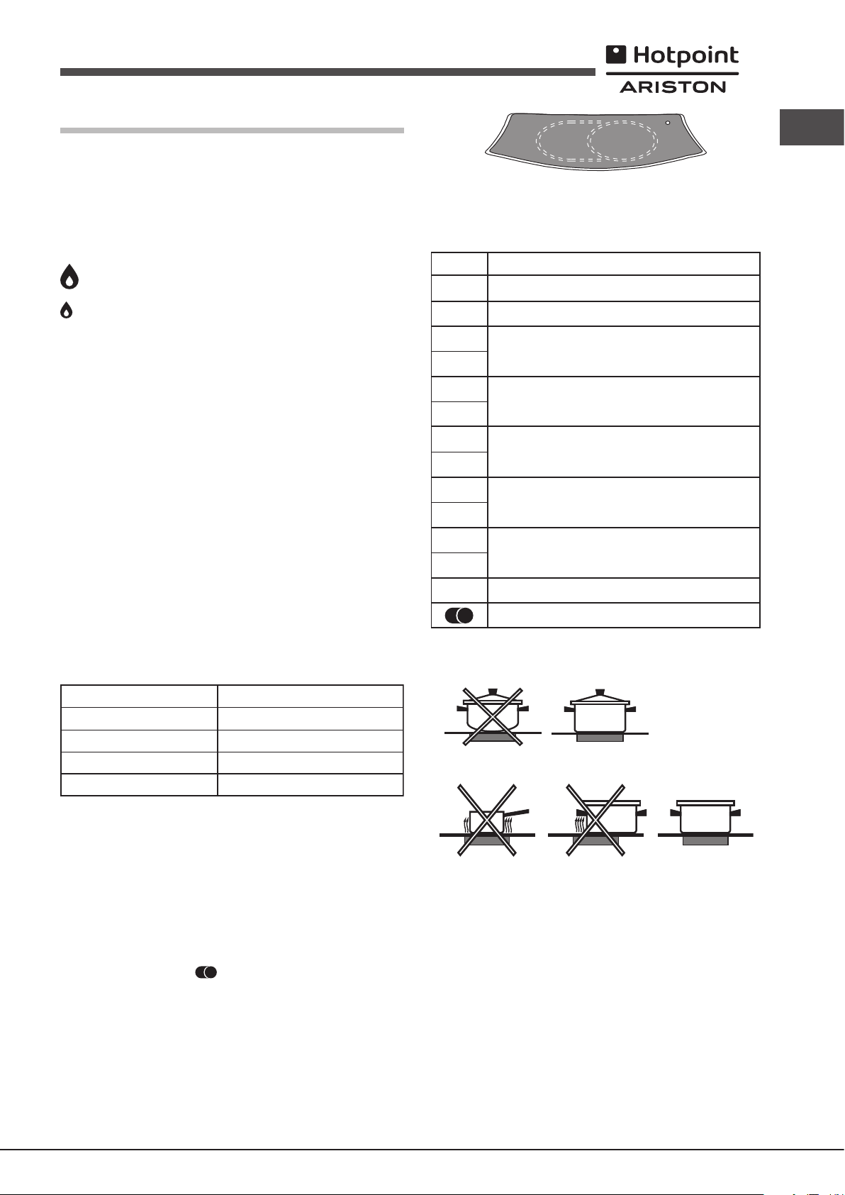
Bekapcsolás és használat
A
C
B
! A megfelelő gázégő vagy elektromos főzőlap helye minden gombon fel
van tűntetve.
Gázégők
Az egyes gázégők a következők szerint állíthatóak be a hozzájuk tartozó
vezérlőgomb használatával.
● KI
Maximum
Minimum
Az egyik gázégő begyújtásához tartson egy égő gyufát a gázégő közelébe, és
ezzel egy időben nyomja be, és forgassa el a gombot az óramutató járásával
ellenkező irányba a maximális állásra. Mivel a gázégő rendelkezik biztonsági
eszközzel, a gombot 2-3 másodpercig nyomva kell tartani, hogy a láng égve
maradjon, és az automatikus rendszer kellően felmelegedjen. Ha gyújtás
gombbal rendelkező típust használ, a kívánt gázégő meggyújtásához nyomja
be a megfelelő gombot amennyire csak lehet, és forgassa azt az óramutató
járásával ellentétes irányba a maximális állásra.
! Abban az esetben, ha az egyik láng véletlenül kialudna, forgassa KI állásba
a vezérlőgombot, és mielőtt újra meggyújtaná, várjon 1 percet.
A gázégő kikapcsolásához forgassa az óramutató járásával megegyező
irányba ütközésig (amíg a gomb le nem éri a „●” állást.
Gyakorlati tanácsok a gázégők használatához
Az égők hatékony működése érdekében:
• Az egyes égőkhöz megfelelő edényt használjon (lásd a táblázatot), hogy
a a láng ne érjen túl az edény alján.
• Mindig lapos fenekű edényt használjon, fedővel.
• Amikor az edény tartalma eléri a forráspontot állítsa a vezérlőgombot
minimum állásba.
Gázégő
Csökkentett gyors (RR)
Kőzepes égő (S)
Segéd égő (A)
Hármas Corona (TC)
Ø
Főzőedény-átmérő
24 - 26
16 - 20
10 - 14
24 - 26
(cm)
Ha a gomb nem „Off” (Ki) állásban van, a kerámiaüveg modul jelzőfénye
bekapcsol.
Gyakorlati tanácsok a kerámiaüveg modul használatához
Beállítás
10
11
12
Így érheti el a legjobb eredményt a főzőlappal:
• Sík fenekű edényeket használjon, hogy azok megfelelően felfeküdjenek
a főző zónához.
• Az edények átmérője legyen elég nagy, hogy teljesen eltakarja a
főzőfelületet, így a teljes hőmennyiséget felhasználhatja.
Sugárzó gázégő
0
Ki
1
Vaj és csokoládé megolvasztásához.
2
Folyadékok melegítéséhez.
3
4
Krémekhez és szószokhoz.
5
6
Étel főzése a forrásponton.
7
8
Sültekhez.
9
Nagyobb darab húsok főzéséhez.
Sütéshez.
Mindkét főzőterület kihasználásához.
HU
A gázégő típusának azonosításához tekintse meg az „A gázégők és fúvókák
jellemző adatai” című fejezetben található ábrákat.
Üvegkerámia modul*
A főzőlap kétgyűrűs kör alakú fűtőelemekkel van felszerelve, melyek az üveg
alatt találhatóak. Lehetséges csak az egyik kör alakú elemet bekapcsolni
(„A” betű jelöli), de a főzőfelület meg is növelhető, ha az „A” és „B”
elemeket együtt kapcsolja be. Ha csak az „A” elemet szeretné bekapcsolni,
egyszerűen forgassa a gombot az óramutató járásával egyező irányba az
elérhető 12 beállítás egyikére. A „B” rész hozzáadásához állítsa a gombot a
12. beállításra, majd kattintsa állásba. Ezt követően a gombot forgassa
az óramutató járásával ellenkező irányba a 12 beállítási lehetőség egyikébe.
Az ábrán a fűtő zónák láthatóak, amik pirosak lesznek, ha az elem be van
kapcsolva.
A. Kör alakú fűtő zóna;
B. Kiterjesztett fűtő zóna;
C. Visszajelző fény, amely jelzi, ha a főző zóna hőmérséklete 60 °C fölött
van, még akkor is, ha a fűtőelem ki van kapcsolva.
• Ügyeljen rá, hogy az edények alja mindig száraz és tiszta legyen, így
biztosíthatja a megfelelő felfekvést és a hosszú élettartamot, nem csak a
főzőlap számára, hanem az edény számára is.
• Ne használja azokat az edényeket, amiket gázégőkhöz használ: a gázégők
koncentrált hőleadása deformálhatja az edény fenekét, így az nem fekszik
fel megfelelően.
• Soha ne hagyja bekapcsolva a főző zónákat, ha nincs rajtuk edény,
mert gyorsan felmelegszik és eléri a maximális szintet, ami kárt tehet a
fűtőelemekben.
! Előfordulhat, hogy az üveg szigeteléséhez használt ragasztóból zsírnyomok
maradtak a készüléken, amit kímélő tisztítószerrel távolítson el a készülék
használata előtt. Az első néhány órányi használat alatt gumiszagot érezhet,
de ez gyorsan eltűnik.
25
Page 26
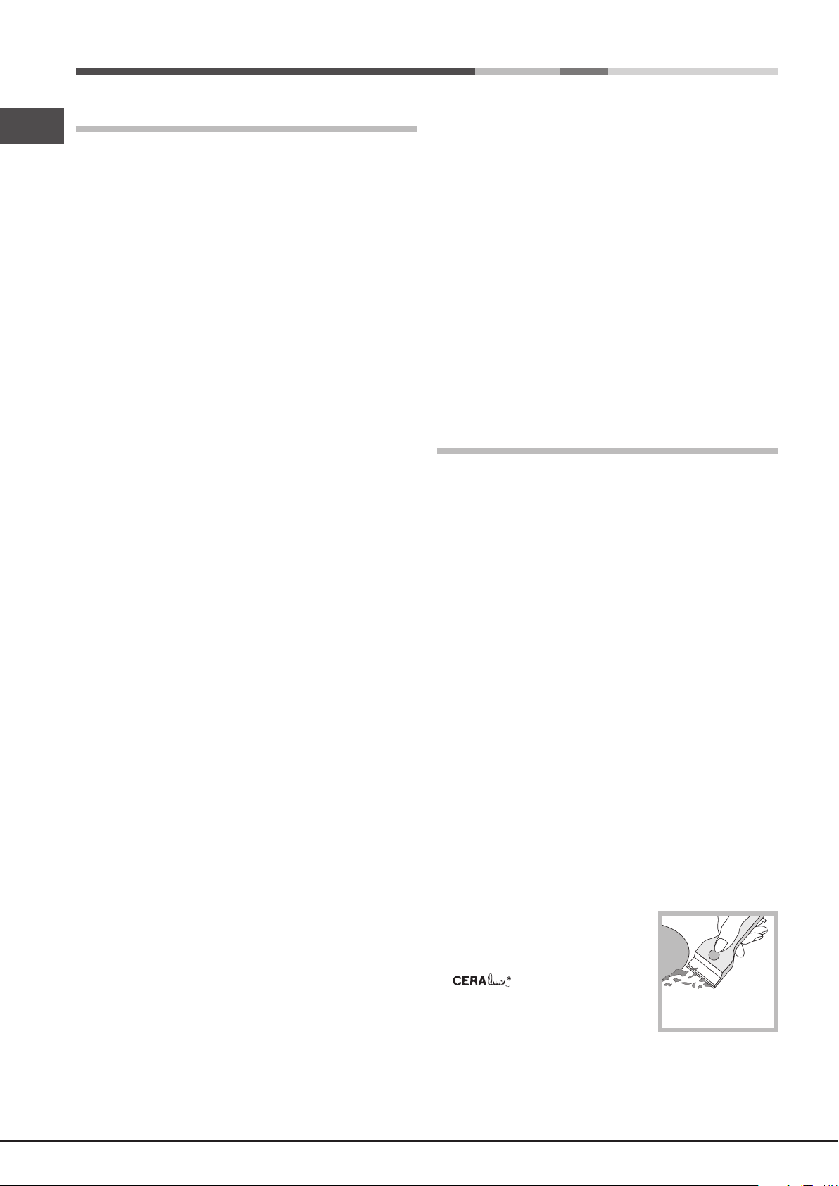
Óvintézkedések és tanácsok
HU
! A készülék a nemzetközi biztonsági szabványokkal összhangban lett
tervezve és gyártva. E gyelmeztetéseket biztonsági megfontolásból közöljük,
kérjük, olvassa el gyelmesen.
Általános biztonság
• Ez a készülék 3. osztályú beépíthető készülék.
• A gázkészülékeknek a megfelelő működésükhöz szabályos
szellőzésre van szükségük. Győződjön meg arról, hogy
beszerelésükkor az „Elhelyezés” című fejezetben leírt követelmények
be lettek tartva.
• Az utasítások csak azon célországok számára érvényesek, melyek
szimbólumai megtalálhatóak a kézikönyvön és az adattáblán.
• A készüléket otthoni, háztartási használtra tervezték.
• A készülék nem helyezhető üzembe nyitott térben, még akkor sem, ha a
terület védett helyen van, mivel rendkívül veszélyes a készüléket esőnek,
viharnak kitenni.
• A készülék elmozdításához mindig használja a sütő oldalain található
megfelelő fogantyúkat.
• Ne érjen a készülékhez mezítláb, illetve vizes vagy nedves kézzel vagy
lábbal.
• A készüléket kizárólag felnőttek használhatják ételek sütésére a
kézikönyvben található útmutatásoknak megfelelően. Minden más
használatra (például: helyiségek fűtésére) alkalmatlan és ezért
veszélyes. A gyártó nem vonható felelősségre olyan károkért,
amelyek szakszerűtlen, hibás, vagy nem rendeltetésszerű
használatból adódnak.
• Ne takarja el a szellőzésre és a hő elosztására szolgáló nyílásokat.
• Ha a készüléket nem használja, mindig győződjön meg arról, hogy a
gombok “●”/“○” állásban vannak.
• A csatlakozót az elektromos hálózatból ne a kábelnél, hanem a
csatlakozódugónál fogva húzza ki.
• A készülék tisztítását vagy karbantartását azután kezdje el, hogy kihúzta
a csatlakozódugót az elektromos hálózatból.
• Meghibásodás esetén semmilyen körülmények között ne próbálja
megjavítani a belso szerkezeteket! Hívja a szervizt (lásd Szerviz).
• Győződjön meg arról, hogy az edények nyele mindig a főzőlap belseje
felé néz, hogy azokat véletlenül se lökhesse meg.
• Ne csukja le az üvegtetőt (ha van), ha a gázégők még melegek.
• Ne használjon instabil vagy deformálódott edényeket.
• A készüléket testileg, érzékszervileg vagy szellemileg korlátozott, nem
hozzáértő, illetve a terméket nem ismerő személyek – a gyerekeket is
ideértve – csak a biztonságukért felelős személyek felügyelete mellett,
illetve a készülék használatával kapcsolatos alapvető utasítások
ismeretében használhatják.
• Vigyázzon, hogy a gyerekek ne játsszanak a készülékkel.
• A készülék nem úgy lett tervezve, hogy külső kapcsolóautomatával
vagy különálló távvezérléssel legyen működtetve.
A tulajdonosok, elektromos háztartási gépük forgalomból történő
helyes kivonásával kapcsolatban, további információért a megfelelő
közszolgálathoz, illetve a forgalmazóhoz is fordulhatnak.
Takarékosság és környezetvédelem
• Használja ki a főzőlap maradék hőjét: ehhez az öntött vas főzőlapot
kapcsolja ki a sütési idő vége előtt 10 perccel, míg az üvegkerámia
főzőlapot kapcsolja ki a sütési idő vége előtt 5 perccel.
• A fazéknak vagy serpenyőnek le kell fednie a főzőlapot. Ha ez kisebb,
akkor ez értékes energiaveszteséget okoz és ha a forrásban lévő étel
kicsordul, akkor ez nehezen eltávolítható lerakodást képez.
• Az ételt jól záródó fedéllel letakart fazékban és serpenyőben főzze meg
a lehető legkevesebb víz használatával. A fedél nélküli főzés jelentősen
megnöveli az energiafogyasztást.
• Teljesen sima fazekakat és serpenyőket használjon.
• Ha olyan ételt készít, melyet sokáig kell főzni, akkor használjon kuktát,
mert ez kétszer gyorsabb és megspórolja vele az energia egyharmadát.
Karbantartás és ápolás
A készülék kikapcsolása
A készüléken végzett minden művelet előtt áramtalanítsa a készüléket.
A készülék tisztítása
! Na használjon súroló vagy korrozív hatású tisztítókat, mint folteltávolítót,
rozsdamaró termékeket, por alapú tisztítószereket, vagy súrolófelülettel
rendelkező szivacsot, ezek javíthatatlan karcokat hozhatnak létre a felületen.
! A készülék tisztításához soha ne használjon gőztisztítót vagy nagynyomású
tisztítót.
• Általában elegendő ha a főzőlapot megtisztítja egy nedves szivaccsal
majd egy nedvszívó törlőkendővel szárazra törli azt.
• Az égők eltávolítható alkatrészeit rendszeresen tisztítsa meg meleg,
szappanos vízzel a felületről az odaégett anyagokat távolítsa el.
• Az automatikus gyújtóberendezéssel ellátott főzőlapoknál rendszeresen
tisztítsa meg alaposan az automatikus gyújtóberendezés érzékelőinek
végeit, és győződjön meg arról, hogy a gázkimenetek nincsenek
eltömődve.
• A kerámia üveg használata előtt, annak felületét egy nedves törlőkendővel
tisztítsa meg, távolítsa el arról a port és az ételmaradékokat. A
kerámiaüveget rendszeresen tisztítsa meg meleg vízzel és nem dörzsölő
hatású tisztítószerrel.
• A rozsdamentes acélon a felületet hosszú ideig érő kemény víz, vagy az
erős foszfor tartalmú tisztítószerek nyomot hagyhatnak. Tisztítás után
alaposan öblítse le és törölje szárazra.
Hulladékkezelés
• A csomagolóanyag hulladékkezelése: tartsa be a helyi előírásokat, így a
csomagolóanyag újra felhasználásra kerülhet.
• Az Európai Parlament és Tanács, elektromos és elektronikus
berendezések hulladékairól (WEEE) szóló 2012/19/EU irányelve előírja,
hogy e hulladékok nem kezelhetők háztartási hulladékként. A forgalomból
kivont berendezéseket – az azokat alkotó anyagok hatékonyabb
visszanyerése, illetve újrahasznosítása, valamint az emberi egészség
és a környezet védelme érdekében – szelektíven kell gyűjteni.Az összes
terméken megtalálható áthúzott szemetes szimbólum a szelektív gyűjtési
kötelezettségre emlékeztet.
26
Rendszeres időközönként különleges
termékekre lesz szükség a felület
tisztításához. Először távolítsa el az
étel vagy zsírfoltokat egy kaparóval, pl.
(nincs mellékelve).
Még langyos állapotban tisztítsa meg a
főzőfelületet a megfelelő tisztítószerrel (pl.
a Solutions termékvonal egyik tagjával,
melyet ügyfélszolgálati és szerviz központjainkban beszerezhet) és papír
törlőkendővel. Majd dörzsölje át nedves és száraz kendővel. Az alufóliát,
műanyag tárgyakat, szintetikus anyagból készült dolgokat, cukrot vagy
magas cukortartalmú ételeket, melyek a felületre olvadtak, azonnal el kell
távolítani egy kaparóval, amíg a főzőfelület még forró.
Page 27
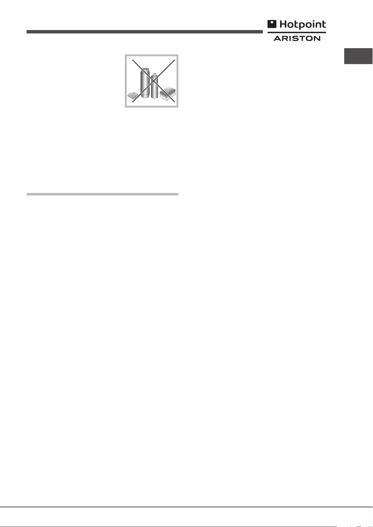
A kerámiaüveg felületekhez készült
speciális tisztítószerek átlátszó
védőréteget képeznek, melyek gátolják
a szennyeződések felgyülemlését. Ez
megvédi a felületet a magas cukortartalmú
ételek által okozott sérüléstől is. Soha
ne használjon súroló szivacsot vagy
súrolószereket. Ugyanez vonatkozik a
kémiailag agresszív tisztítószerekre is, mint a sütőtisztítók és folteltávolítók.
A gázcsapok karbantartása
Idővel a csapok eltömődhetnek, illetve kinyitásuk nehézzé válhat. Ebben az
esetben cserélje le az érintett csapokat.
! Ezt a műveletet csak a gyártó által felhatalmazott szakember végezheti.
Hibaelhárítás
Előfordulhat, hogy készülék nem működik megfelelően. Mielőtt a szervizhez
fordulna segítségért, ellenőrizze nem tehet-e valamit. Először ellenőrizze,
hogy nincs-e fennakadás az gáz vagy elektromos ellátásban, ellenőrizze,
hogy a gázcsapok nyitva vannak-e.
HU
Az égő nem gyullad meg vagy a láng nem egyenletesen oszlik el az
égő körül.
Ellenőrizze hogy:
• Az égőn található gáznyílások nincsenek-e eltömődve.
• Az égő mozgatható alkatrészei megfelelően vannak-e felszerelve.
• A készülék környékén huzat van.
A biztonsági berendezéssel ellátott készüléke esetében a láng elhal.
Ellenőrizze a következőket:
• Teljesen benyomta-e a gombot.
• Elég hosszan nyomja-e be a gombot a biztonsági eszköz aktiválásához.
• A gáznyílások nincsenek-e eltömődve a biztonsági eszköz környékén.
Minimum állásban a az égő elalszik.
Ellenőrizze a következőket:
• A gáznyílások nincsenek-e eltömődve.
• A készülék környékén nincs-e huzat.
• A minimális állás beállítása megfelelően megtörtént-e.
Az edény billeg.
Ellenőrizze a következőket:
• Az edény alja teljesen lapos-e.
• Az edény megfelelően van-e az égő közepére helyezve.
• Az edénytartó rács megfelelően van-e felhelyezve.
27
Page 28

HU
Indesit Company S.p.A.
V
60044 Fabriano (AN)
www.hotpoint.eu
195130969.00
03/2015 - XEROX FABRIANO
iale Aristide Merloni,47
28
 Loading...