

Page 1
Indesit Company UK Ltd
© 2010 Reg. Office: Peterborough PE2 9JB Registered in London: 106725
Service
Information
Aqualtis
8 Kg
"A Energy"
CONDENSER
ELECTRONIC
TUMBLE DRYER
with
Refrigerant
Condenser System
Models Comm
Covered Code
AAQCF81U IT 70078
AAQCF81U WE 71832
AAQCF81U UK 71846
5407535 Issue 2 May 2010
..
C00279765
Page 2
2 of 36
Service Manual UK
Indesit
Company
English
SAFETY NOTES & GENERAL SERVICING ADVICE
1. This manual is NOT intended as a comprehensive repair/maintenance guide to the appliance.
2. It should ONLY be used by suitably qualified persons having technical competence applicable
product knowledge and suitable tools and test equipment.
3. Servicing of electrical appliances must be undertaken with the appliance disconnected (unplugged)
from the electrical supply.
4. Servicing must be preceded by Earth Continuity and Insulation Resistance checks.
5. Personal safety precautions must be taken to protect against accidents caused by sharp edges on
metal and plastic parts.
6. After Servicing the appliance must be rechecked for Electrical Safety. In the case of appliances which
are connected to a water supply (i.e.: Washing Machines, Dishwashers & Food Centres etc.) checks
must be made for leaks from seals gaskets and pipe work and rectification carried out where
necessary.
7. It can be dangerous to attempt ‘DIY’ repairs / maintenance on complex equipment and the Company
recommends that any problem with the appliance is referred to its own Service Organisation.
8. Whilst the Company has endeavoured to ensure the accuracy of the data within this publication they
cannot hold themselves responsible for any inconvenience or loss occasioned by any error within.
INDEX
Safety Notes & General Servicing Advice . . . . . . . . . . . . . . . . . . . . . . . . . . . . . . . . . . . . . . . . . . . . . 2
Technical Specifications. . . . . . . . . . . . . . . . . . . . . . . . . . . . . . . . . . . . . . . . . . . . . . . . . . . . . . . . . . . 3
Dryer Function . . . . . . . . . . . . . . . . . . . . . . . . . . . . . . . . . . . . . . . . . . . . . . . . . . . . . . . . . . . . . . . . .4 - 6
Installation . . . . . . . . . . . . . . . . . . . . . . . . . . . . . . . . . . . . . . . . . . . . . . . . . . . . . . . . . . . . . . . . . . . . . . 6
Filter Care . . . . . . . . . . . . . . . . . . . . . . . . . . . . . . . . . . . . . . . . . . . . . . . . . . . . . . . . . . . . . . . . . . . . . . . 7
Water Drain - Plumbing Out . . . . . . . . . . . . . . . . . . . . . . . . . . . . . . . . . . . . . . . . . . . . . . . . . . . . . . . . 8
Console Functions . . . . . . . . . . . . . . . . . . . . . . . . . . . . . . . . . . . . . . . . . . . . . . . . . . . . . . . . . . . .9 - 12
Component Description . . . . . . . . . . . . . . . . . . . . . . . . . . . . . . . . . . . . . . . . . . . . . . . . . . . . . . .13 - 16
Special Programmes . . . . . . . . . . . . . . . . . . . . . . . . . . . . . . . . . . . . . . . . . . . . . . . . . . . . . . . . . . . . . 17
Programme Guide . . . . . . . . . . . . . . . . . . . . . . . . . . . . . . . . . . . . . . . . . . . . . . . . . . . . . . . . . . . .18 - 19
Control Board Programming . . . . . . . . . . . . . . . . . . . . . . . . . . . . . . . . . . . . . . . . . . . . . . . . . . .20 - 21
Fault Codes . . . . . . . . . . . . . . . . . . . . . . . . . . . . . . . . . . . . . . . . . . . . . . . . . . . . . . . . . . . . . . . . .22 - 23
Servicing Notes . . . . . . . . . . . . . . . . . . . . . . . . . . . . . . . . . . . . . . . . . . . . . . . . . . . . . . . . . . . . . .24 - 25
Test Sequence . . . . . . . . . . . . . . . . . . . . . . . . . . . . . . . . . . . . . . . . . . . . . . . . . . . . . . . . . . . . . . . . . . 26
Wiring Diagram . . . . . . . . . . . . . . . . . . . . . . . . . . . . . . . . . . . . . . . . . . . . . . . . . . . . . . . . . . . . . . . . . 27
Power Module Connections . . . . . . . . . . . . . . . . . . . . . . . . . . . . . . . . . . . . . . . . . . . . . . . . . . . . . . . 28
Dismantling Instructions. . . . . . . . . . . . . . . . . . . . . . . . . . . . . . . . . . . . . . . . . . . . . . . . . . . . . . .29 - 34
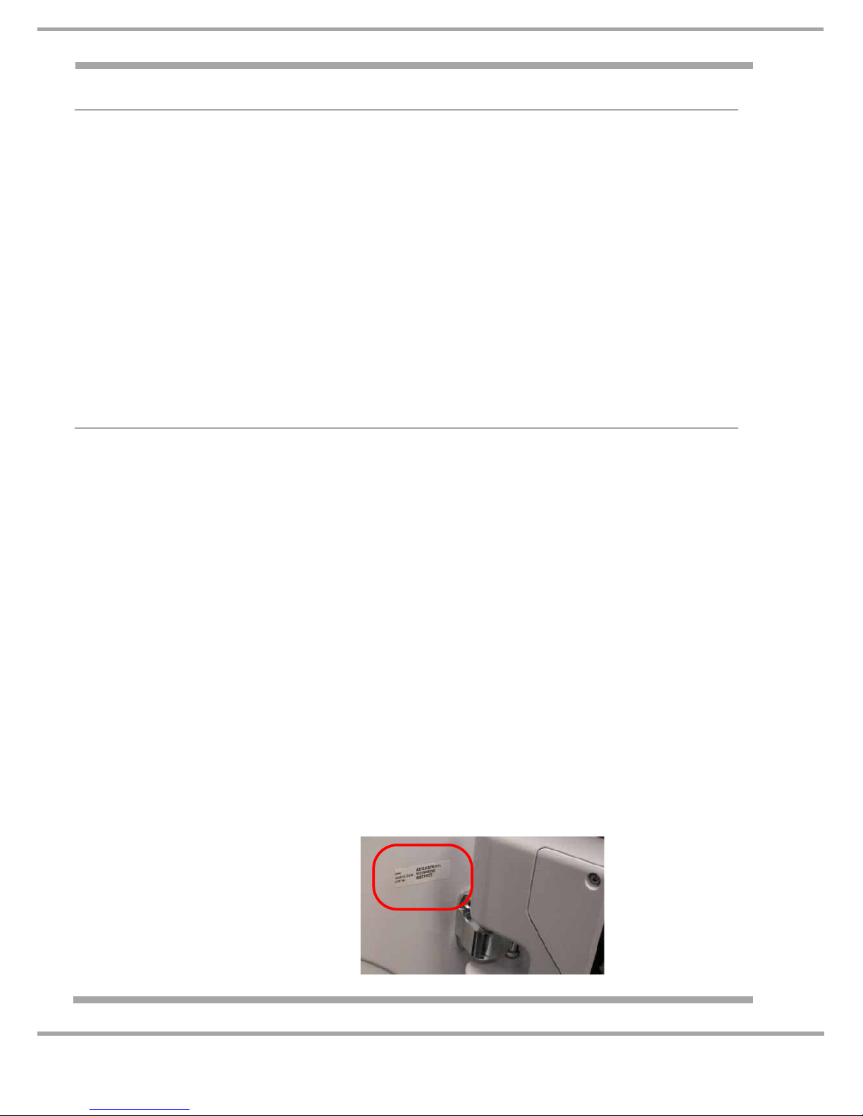
Serial Number Location
The Serial Number is located on the front
panel behind the door - open the door to
see it.
Page 3

3 of 36
Indesit Company
Service Manual UK English
TECHNICAL SPECIFICATIONS
First Production June 2010
General Model Colour Commercial Code
AAQCF81U IT White / Silver Door 70078
AAQCF81U WE White / Silver Door 71832
AAQCF81U UK White / Silver Door 71846
Features Electronically controlled tumble dryer comprising of an interface
module
fitted into the door and a control module mounted on the plinth,
connected by a serial link cable.
The Condensing Drying System uses an integrated self contained
refrigerant module instead of traditional high wattage heaters.
Country of Origin Great Britain
Dimensions Height 850 mm
Width 595 mm
Depth 584 mm
Weight 48 Kg (Unpacked), 51 Kg (Packed)
Energy Class A
Noise Level 68 dBA approximately
Drum Volume 112 litres
Drying Load Dry weight maximum 8 Kg
Programmes 16 position selector
Drying Sensing Levels Up to 5 depending on programme selected.
Door Operation Lever operated door catch
Electronic Platform EVO2
Drying Controls Variable using electronic control and thermistors
System Thermistor) 25°C = 10 K:10%
50°C = 4.16 K:10%
Front Air Duct Thermistor 25°C = 470 K:15%
100°C = 16.15 K:5%
Motor - Type 360 Single phase capacitor run 2 pole induction motor - 2800 rpm
Motor Capacitor 8.5 uF
Compressor Highly BSD 122DV - H3BD1, 200-240V - 50/60Hz
Compressor Capacitor 17 uF
Cooling Fan 220-240V AC, 50/60Hz, 0.14 Amp
Refrigerant Type R134a
Refrigerant Charge 340 grams
Water Container Capacity 5 Litres
Absorbed Power 1.04 - 1.15 kW (220 - 240 V AC)
Page 4

4 of 36
Service Manual UK
Indesit
Company
English
DRYER FUNCTION
Overview
This is a freestanding tumble dryer with a full width metal door.
The drum is capable of accepting a maximum 8 kg load. The drum is supported at the front by 2
wheels mounted on the front air duct and a single bearing at the rear located in the rear panel. A
shaft fixed to the rear of the drum runs in the rear bearing. The drum is driven by a belt which passes
around its periphery and onto the shaft of a motor secured to the base of the dryer.
The belt is tensioned by a pulley mounted to the motor.
The motor also drives a fan fixed to the end of the rear shaft to recirculate air through the drum.
The drum normally rotates clockwise with the occasional reverse action anticlockwise. This occurs
during the cycles cool down period and for 5 minutes every hour of the cycle duration.
The moisture removed from the recirculating air, by means of a refrigerant module, is pumped to a
removable container mounted in the left hand side of the console. The user can easily withdraw the
container to dispose of the collected condensed water. There is no requirement for venting to
atmosphere on this dryer.
Drying Process
The circulating air flows over the condenser unit causing it to be heated, the air then passes into the
drum via the fan chamber collecting moisture from the clothes enabling them to dry. The moisture
laden air passes through two filters to remove any lint and then passes through the evaporator unit
where the moisture condenses and falls into a channel in the base and flows into the pump reservoir
where it is pumped into the water container. The resulting cooled air aids the cooling of the
refrigerant in the condenser before starting the process again.
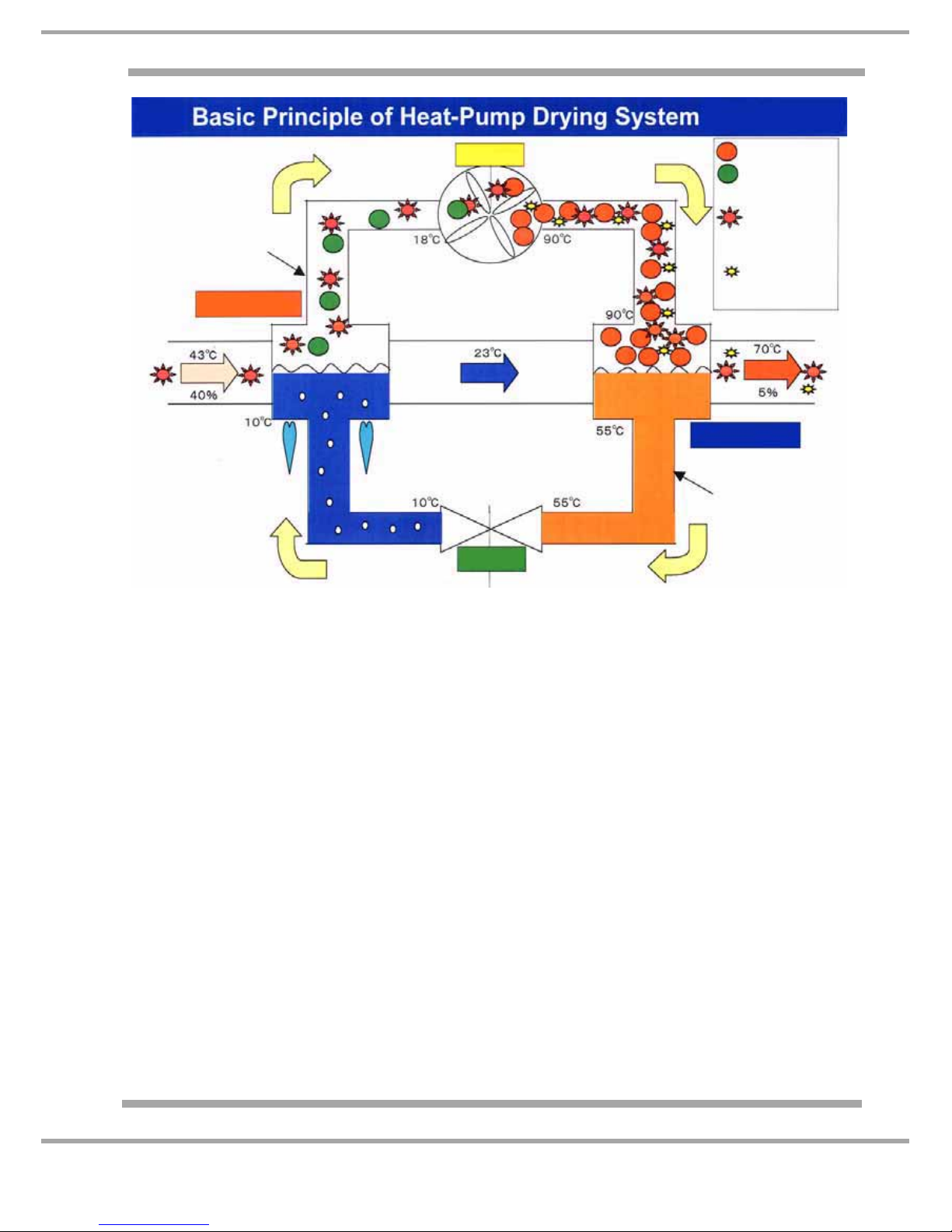
Heat Exchange Cycle
The Cycle begins with refrigerant being pumped by the compressor through the condenser unit.
A capillary tube is used to create a restriction to increase the pressure and temperature of the
refrigerant in the condenser, the heat (used to heat the airflow into the dryer) is removed from the
refrigerant converting it from a gas to a liquid.
The liquid refrigerant is then forced through the capillary under pressure into the evaporator unit
where the pressure is removed causing the refrigerant to evaporate into a gas again cooling the
evaporator the refrigerant then returns to the compressor to complete the cycle.
Controls Overview
The user interface controls consist of a Programme selection knob, a Digit display, option buttons;
Start/Pause button and an On/Off button.
The control system consists of a control module, two thermistors and a conductivity sensor.
The conductivity sensor is mounted in the front air duct. A single wire connects the sensor to the
control module. The front thermistor is located in the air duct, and the second thermistor is attached
to the heat exchanger system pipe work.
The control module determines the programme duration and dryness of the load. This is achieved
by the thermistors located in the front air duct and on system pipe work measuring the difference in
temperature / resistance between the two points, the control module then calculates and compares
the values to that of the chosen programme.
As the programme progresses a small DC current is passed from the sensor in the front air through
damp clothes to earth. The resistance of this current is compared to the resistance value of the
chosen programme and when these become equal the load will have reached the required level of
dryness and will then progress through the dry programme and on to the cool down period.
Page 5
5 of 36
Indesit Company
Service Manual UK English
The control module is located behind the right hand side panel and there is a service port behind the
plinth cover that allows attachment of a computer, Smart Card Reader or Handheld Device to
programme the Control Module.
The control module can be programmed with the relevant settings file if the module is replaced, the
settings file becomes corrupted or if an updated file becomes available.
Each of the sensing programmes has a maximum time of approximately 270 minutes. (Actual time
will vary slightly due to programme selected).
Auto Sensing
After the Automatic cycle has started, the machine’s thermistor and conductivity sensor continually
monitor the dampness of the drying clothes. Once a final dry time has been determined, the display
will update, and the cycle will continue finishing with a 3 minute cool down period. The time taken to
update will vary depending on the Programme set, load and the ambient temperature.
If the display counts down to 3 minutes and the clothes are not at the required dryness level, the
display will hold at 3 minutes, depending on the programme in progress and the material being dried,
the dryer will either wait until the correct dryness level is reached and move to the cool down period,
or wait until the machines sensors are able to recalculate the dryness time and the display will
update accordingly.
If, after the maximum programme time of approximately 270 minutes, the clothes are still not dry,
the programme advances to cool tumble and completes the programme.
Note 1: No fault is indicated if this occurs.
Note 2: The actual time out period will vary slightly depending on the programme and dryness level
set. Under normal drying conditions providing at the start of the cycle the water container is empty,
Gas
Circulated
Calorific Value
(1600W)
Calorific Value
given by
Compressor
(600W)
High Pressure
1.6MPa
Low Pressure
0.3MPa
Compressor Motor
Gas
Dew Condensation
Water
Heat
Exchanger
(Evaporate)
Heat
Exchanger
(Condense)
Low Pressure
0.3MPa 1.6MPa
High Pressure
Liquid
Expansion
Evaporate
Condense
Compress
Page 6
6 of 36
Service Manual UK
Indesit
Company
English
both filters are clean and the clothes have been spun in a washing machine, the clothes should dry
before the time out period occurs.
The module also controls the compressor. The compressor will start running at the start of the
programme and is on continually during the drying cycle.
If the user turns off the power or disconnects the mains cable or there is a power cut, the dryer will
remember its last settings and resume the programme when the start button is pressed, the
compressor will restart after a 5 minute delay period to allow the system to equalise.
Note: If the compressor is switched off, i.e: Programme paused or the door is opened, the
compressor will have an ’OFF’ time of approximately 5 minutes to allow the pressure in the system
to equalise.
The start of a programme can be delayed up to a maximum of 24 hours programmed in 1 hour steps.
Pre-crease care (see page 11) can only be selected if a timed delay has been selected; this option
tumbles the clothes for 3 seconds every 30 minutes for the duration of the time delay.
If selected, the Post crease care option (see page 11) tumbles the clothes after the programme has
finished for 3 seconds every 4 minutes up to a maximum duration of 10 hours.
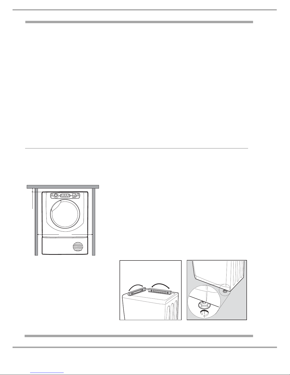
Installation
If the machine has been transported or laid over, the machine must NOT be started for
2 hours to allow any displaced oil in the system to resettle.
Ventilation
The machine must be installed so it has a minimum air gap of
15mm along each side and 10mm at the top. The machine's rear
air vents must not be blocked.
The machine should be installed on a level surface away from
any appliance which produces flames. i.e: a Gas Hob or Gas
Fire.
Levelling the Tumble Dryer
This dryer must be level for correct
operation.
When the dryer is installed in its final
location check that it is level first side-toside, then front to back.
If the dryer is not level, adjust the feet up
or down until the dryer is level.
Rotate the feet to adjust the height.
10 mm
15 mm
15 mm
Page 7
7 of 36
Indesit Company
Service Manual UK English
Environment
Installing in a cupboard is NOT recommended, but the dryer must not be installed behind a locked
or sliding door, or where a door is hinged on the opposite side to the tumble door.
When in use the dryer must be in an environment that is not damp with proper air circulation.
The dryer will not operate efficiently in an enclosed space or cupboard.
Door Reversal: The Tumble Dryer door cannot be reversed.
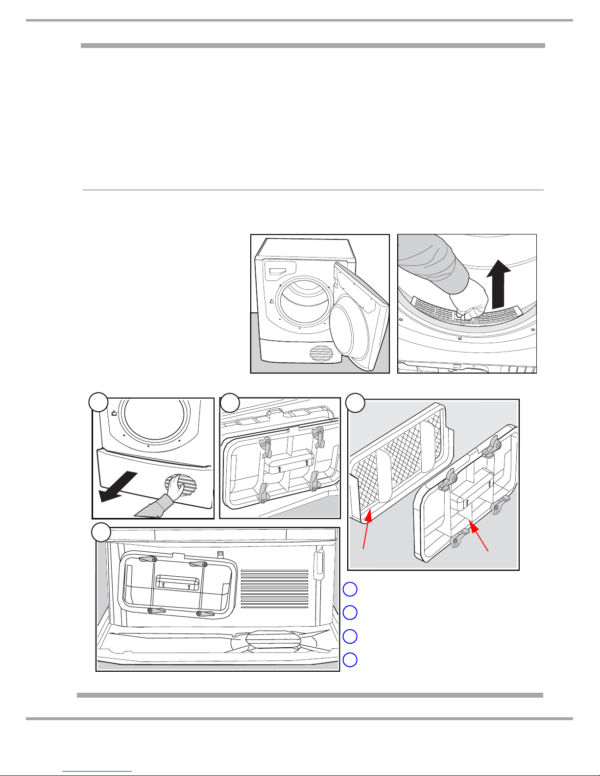
Filter Care
This A class Dryer has 2 filters which must be kept clean to ensure efficient and correct operation of
the dryer.
1. Air Duct Filter
Open the machine door (A).
Remove the filter, located just
inside the opened door. (B)
Unclip the filter, and open.
The filter can now be cleaned
and the fluff removed.
Replace the filter after cleaning.
2. Heat Exchanger Filter
B
A
1
2 3
4
1 Pull the plinth forward
2 Rotate the cover fixing clips
3 Clean the filter
4 Refit the cover and rotate the clips
Filter Cover
Page 8
8 of 36
Service Manual UK
Indesit
Company
English
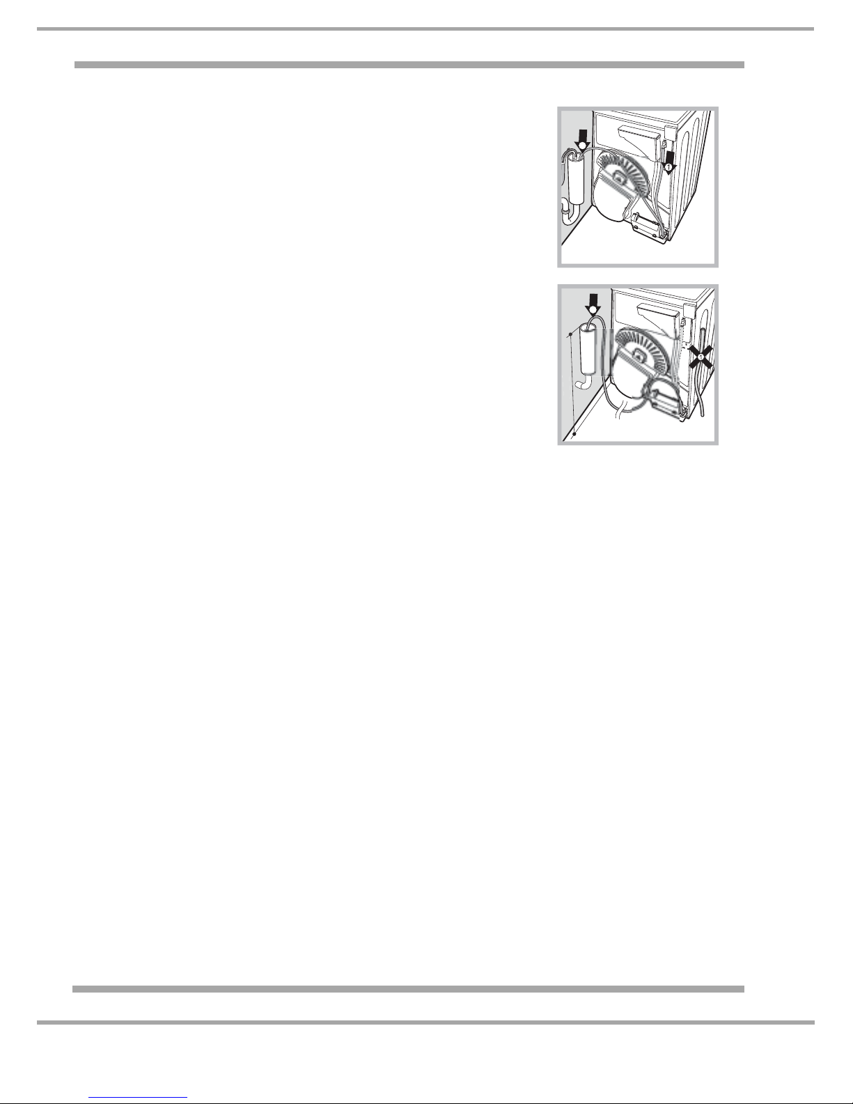
Water Drain - Plumbing Out
If the Dryer is positioned close to a drain or standpipe, it is possible to
drain the condensed water directly without using the water bottle.
In this case it is no longer necessary to empty the water bottle at the
end of each cycle.
lf the Dryer is positioned above or close to a Washing Machine which
uses a standpipe the same standpipe can be used.
Just disconnect the tube indicated in Figure A and connect it to the
drain.
If the standpipe / drain is further away than the length of the tube it is
possible to buy and connect a tube of the same diameter and the
necessary length in order to reach the standpipe.
To install the new tube just substitute the existing one as indicated in
Figure B inserting it in the same place.
Important Notes:
- The top of the standpipe must be below 1 metre from the bottom of
the Dryer.
- Once the Dryer has been installed, ensure that the drain tube is not
bent, squashed or contorted.
2
2
Page 9
9 of 36
Indesit Company
Service Manual UK English
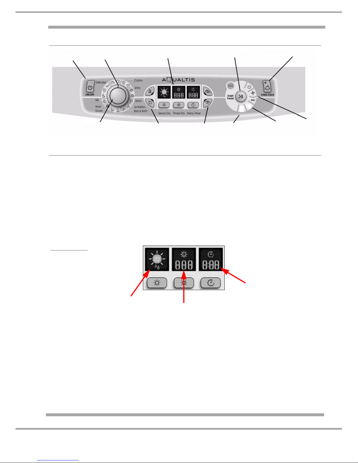
CONSOLE FUNCTIONS
Option Buttons
ON OFF BUTTON and LIGHT
Push to switch the dryer On and Off.
If the button glows the dryer is turned on and either running or waiting to be started.
PROGRAMME KNOB AND INDICATOR
Used to select the required programme option.
16 timed auto and special programmes are available - see page 17.
Consult the programme chart on pages 18 and 19, to see Programme descriptions.
Stand-by Mode
To comply with current energy saving requirements this product features a Stand-by mode. If the
machine has not been switched off for a period of 30 minutes after the finish of the programme the
controls will go into stand-by mode when the LED's and display will switch off.
To reactivate and remove the controls out of Stand-by mode briefly press the On/Off button, the
LED's and display will illuminate and another programme can then be started or the machine
switched off by pressing the On/Off button.
Display
On/Off Button
& Light
Indicator
Display Unit
Start/Pause Button
Child Lock Button
Programme
Option Button & Lights
Clean Heat
Progress
Lights
& Light
& Light
Exchange
Empty Water/
Clean Filter Light
Filter Light
Knob
Indicates Current
Dryness Level
Sensor cycles only
(See Sensing Levels)
Active. Auto Cycles
only
Indicates Time Set
Active. Manual Time
Cycles Only
Countdown Timer
Gives Estimated time to
end of delay or cycle
Displays during delay
start, auto, special and
manual programmes.
Page 10
10 of 36
Service Manual UK
Indesit
Company
English
Display Information
Note:
During Sensor Cycles the Centre Timed display screen is blank
During Timed Cycles the left hand Sensor screen is blank
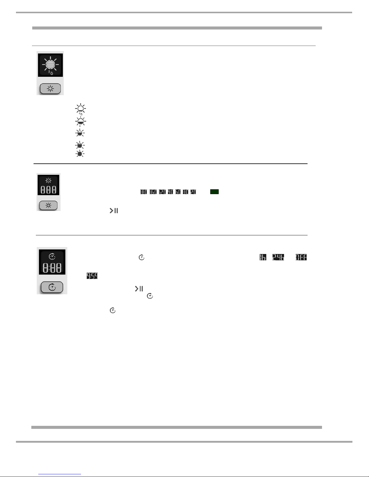
Sensing Levels
After selecting a programme that has a Sensing Dry Option, press and release the button until the
required dryness sensing level is displayed. If the sensing option is not available the display will ash
and the buzzer beeps three times.
Note: ‘Cottons - High Heat’ and ‘Jeans’ programmes are the only programmes which have all ve
dryness level options - all other programmes have only 4 options.
Dryness levels available
Damp Dry
: Dries your items ready to be ironed using a machine or rotary ironer.
Iron Dry
: Dries you items ready to be ironed with a hand iron.
Hanger Dry: Dries you clothes ready to be hanged for nal drying; Use this program if
you do not need the items to be fully dry as it uses less Energy.
Cupboard Dry
: Dries your items ready to be put away.
Ready to Wear / Extra Dry
: Dries your clothes ready to be worn.
Timed Dry
After selecting a Programme that has a Timed Dry Option, press theTimed Button and the display will
Note: Timed Dry is only available on the following programmes:
Cottons - High Heat, Cottons - Low Heat, Shirts - High Heat, Shirts - Low Heat, Synthetics, Delicates.
reduce the selected time each time you press and release this button (see Start and Programmes).
Each press decreases the set time
, , , , , , , then and then repeats.
If the Timer Dry option is not available the display will ash and the buzzer beeps three times.
The selected time remains displayed after the programme starts and cannot be changed after the after the
Start/Pause Button
is Pressed.
Delay Timer
After selecting a Programme that has a Delay Timer Option a delay start time can be selected.
Each press of the Delay button
advances the delay setting in 1 hour Increments from to then
and then after ve seconds cancels the delay.
For delays of 10 hours or more the display counts down the time in hours for rst ten hours, then the display
shows
and then counts down in minutes. For delays less then 9 hours or less the display shows hours
and minutes and then count down in minutes for all of the delay.
After the Start/Pause Button
is pressed the time cannot be changed.
When the delay period nished the
symbol is o and the Time to End is displayed
Time to End
If the delay icon
is o the time displayed is the Time to End of the programme running.
When timed programmes are selected the time displayed throughout the cycle is the actual time
remaining.
When an Automatic programme is selected the time displayed is an estimate of the time remaining.
When the programme is selected the display shows the time required to dry a full load, after around 10
minutes the controller calculates a better estimate of the cycle time
The time to end is displayed in hours and minutes and counts down each minute.
The colons between the hours and minutes display ashes to show that the time is counting down.
The Display also shows if there is a problem with your dryer, if this occurs the display will show F
followed by a fault code number, the four option lights and the pause light will also ash Orange.
Page 11

11 of 36
Indesit Company
Service Manual UK English
OPTION BUTTONS
1. Mini Load
Should be selected if between 1 & 2 kg of clothes are to be dried.
The Time to END display is adjusted to give a more accurate Cycle Time to end estimation time.
2. Alarm
If selected, the buzzer will sound at the end of the cycle. Beeps 3 times when the cycle finishes.
3. Pre-Crease Care
Option can be selected if the Delay Start Option has been selected; the clothes are tumbled
occasionally during the Delay period to help prevent creases developing.
- 3 secs Clockwise
- 30 min Pause
- 3 secs Anti -Clockwise
- 30 Pause--- continuously until programme starts.
4. Post Crease Care
Can be selected, if the clothes will not be removed as soon as the cycle is finished.
This option occasionally tumbles the clothes to prevent creases developing, while the clothes are in
the drum when the cycle is finished.
- 3 secs clockwise
- 237 secs Pause
- 3 secs anti clockwise
- 237secs pause …… continuously until the clothes are removed.
This option will run for a maximum of 10 hours.
1.
2.
3.
4.
Option Buttons & Lights
Page 12

12 of 36
Service Manual UK
Indesit
Company
English
Progress and Warning Lamps
ECO Led
The Eco LED will illuminate when the user adjusts the knob/
option settings, which involve an energy reduction, from the
default settings.
Auto Cycles - If the sensing level is reduced.
Timed Cycles - If the time is a adjusted below the default
programme time.
Child Lock (Button)
To enable the Child Lock function, press and hold the "Child Lock" button until the Button Led
illuminates. All the controls on the dryer are now disabled.
If the selector is turned or an Option is pressed the Child Lock button will flash and the machine will
bleep, to remind the customer that the Child Lock is active.
To remove the controls child lock, press and hold the child lock button and until the button lamp goes
out.
Drying Led
Is illuminated when the machine is drying.
Cool Tumble
Is illuminated, when the dryer is on a cycle, and the compressor is Off, this would be the cool
down period at the end of the cycle.
End
Is illuminated when the programme has finished its cycle.
Empty Water/ Clean Filter
Is illuminated (permanently "ON"), at the end of every cycle as a reminder to the customer to
empty the water container and to clean the filter after every use.
If the Empty Water / Clean Filter Led illuminates during a cycle, (H2) would also be shown in
the display. The machine has sensed the water container is full, after approximately
1 minute the compressor is turned Off and continues for a further 10 minutes with cool air
only, before displaying the fault (H2) and LED. To continue the cycle, empty the container,
push the Start/Pause button and the machine will continue.
Clean Front Heat Exchange Filter
Is illuminated regularly to remind the customer to clean the heat exchange filter. This lamp is
a reminder and does not indicate the state of the filter.
The Heat Exchange Filter must be cleaned after 5 dry cycles. But for Optimum Performance,
it is recommended to clean the Heat Exchange Filter after every use.
Failure to keep this filter clean, will affect the performance of the machine and if the filter
become blocked the machine would not dry.
Page 13

13 of 36
Indesit Company
Service Manual UK English
COMPONENT DESCRIPTION
Door
The Aqualtis Tumble Dryer door holds the customer interface controls and the water container
handle is only visible when the door is opened.
Filters
Two Plastic mesh filters are fitted,
1. Just inside the door, into the Front Air Duct
2. With the plinth open, the filter is located behind the cover.
See also page 7.
Control Module
This is an electronic device that monitors and controls all devices within the appliance. It is located
behind the right-hand Side Panel.
A production Control Module is pre-programmed at the factory.
Drum
The drum comprises of a zinc coated front and rear body and two removable plastic lifters. The rear
of the drum is perforated to allow the passage of air. Fixed to the rear pressing is a support shaft which
runs in a bearing located in the rear panel of the dryer.
Door Switch
A single unit comprising two single microswitches, fitted to
the front panel of the dryer.
- One microswitch signals to the module whether the door is
opened or closed.
- One microswitch disconnects supply to the motor
whenever the door is open.
Pull on Handle
Heat Exchanger
Filter Unit
(cover open)
to open
Customer
Interface
Rating Plate
Water Container
Filter
Model &
Air Intake Grille
Heat Exchanger Filter Unit
(Pull here to open)
Cover - Handle
Serial Numbers
Page 14

14 of 36
Service Manual UK
Indesit
Company
English
A drive pin and collar on the drum shaft prevents forward thrust during use. The front lock seam of the
drum rotates on bearing pads.
Note: Galvanised and Stainless steel drums are used in production, depending on the model of the
dryer.
Compressor Assembly
Pump & Float Switch
Mounted on the bottom right hand side of the rear panel, condensate water from the condenser
chamber is pumped via an external hose to the water container situated behind the console.
The pump runs continually throughout the programme, except for the cool down period at the end of
the cycle.
Cooling Fan
Filter
Compressor
Drier
Evaporator
Condenser
Cover
System
Thermistor
Heat Exchanger
Filter
Page 15

15 of 36
Indesit Company
Service Manual UK English
Air Duct (NTC)
System Thermistor
Compressor Cooling Fan
The cooling fan is located on the RH side at the front of the base moulding immediately behind the
air inlet grill. The fan is controlled by the system pipe work NTC and operates when the NTC senses
a temperature of approximately 53°C on Cotton and Synthetic programmes and 45°C on Delicate
Programmes. The fan will start after about 20 minutes and will switch on intermittently during the
early stages of the Drying cycle.
Compressor
The compressor starts running at the beginning of the programme selected and will run continually
for the duration of the drying programme switching off during cool tumble.
If the power supply to the compressor is interrupted (i.e. if the door is opened) there will be a 5 minute
delay before power is restored, this delay is to enable the refrigeration system to equalise.
Operation of the Float Switch:
The compressor will turn off after
approximately 1 minute, and the machine
will continue, with cool air only for a further
10 minutes, before the warning H20 is
displayed, the Start/Pause button flashes
orange and the empty water container
icon flashes.
Located in the front air duct, this thermistor continually
monitors the temperature of the circulating
drying air.
TEMPERATURE
°C
RESISTANCE
READING
20
°C 614 K ohms
25
°C 470 K ohms
40
°C 217 K ohms
60
°C 84 K ohms
100
°C 16 K ohms
130
°C 5 K ohms
The system thermistor sits in a pocket on the external
system pipe work, and measures the system
temperature. The System Thermistor is used to
control the front cooling fan.
TEMPERATURE
°C
RESISTANCE
READING
25
°C 10.00 K ohms
30
°C 8.313 K ohms
50
°C 4.160 K ohms
60
°C 3.020 K ohms
85
°C 1.450 K ohms
Page 16

16 of 36
Service Manual UK
Indesit
Company
English
This 5 minute delay is controlled by the module and the delay is triggered when the programme is
interrupted for any reason, opening the door, pausing the cycle, power cut etc. This 5 minute delay only
counts down when the machine has the power turned On.
The compressor also has a self setting cut out positioned under the plastic cover on its top, this is
operated by excessive compressor temperature or excess current flow.
Motor
A two pole P.S.C. (permanent split capacitor) running at 2800 rpm with the impeller fitted to the rear
end of the shaft and the drive belt running directly in grooves in the front end of the shaft.
It is protected from overload by a self-resetting internal cut-out that interrupts the electrical supply to
the windings.
It is used together with a capacitor that is mounted on the base of the dryer.
Drum Rear Seal
This unit comprises of a ring of foam with a webbing bearing face. Lubrication is applied to the drum
where the webbing surface runs, to reduce noise and wear. The seal reduces air losses at the rear of
the drum. The joints in the foam are sealed with glue and the joints in the webbing are stitched to further
reduce air leakage.
Compressor Cooling Fan
The cooling fan is located on the RH side at the front of the base moulding immediately behind the air
inlet grill. The fan is controlled by the system pipe work NTC and operates when the NTC senses a
temperature of approximately 45°C or 53°C - depending on the programme selected.
Compressor
The compressor starts running at the beginning of the programme selected and will run continually for
the duration of the drying programme switching off during cool tumble.
If the power supply to the compressor is interrupted (i.e. if the door is opened) there will be a 5 minute
delay before power is restored, this delay is to enable the refrigeration system to equalise.
Page 17

17 of 36
Indesit Company
Service Manual UK English
SPECIAL PROGRAMMES
Note all timings are approximate and assume the clothes have been spun in a washing machine at
a reasonable speed.
All garments should be ready to wear, the edges or seams may still be slightly damp on heavier
garments.
All cycles may take longer than stated due to the density and dampness of the load.
Easy Iron
10 minute programme, 8 minutes of heat followed by 2 minutes of Cool Tumble.
Used to fluff up clothes that have been laid in the same position for a long period.
All cycles may take longer than stated due to the density and dampness of the load.
Wool Safe for clothes marked with this symbol . Max load 1 kg, 3 sweaters.
Programme takes about 60 minutes.
Jeans A maximum load of 3 kg (4 pairs), turn front packets inside out.
Programme will take approximately 115 minutes
Shirts
High Heat
Shirts made from cotton. Maximum load of 3 kg (14 shirts).
Programme takes approximately 95 minutes.
Shirts
Low Heat
Shirts made of synthetic cycles Maximum load of 3 kg (14 shirts)
Programme takes approximately 75 minutes.
Silk Delicate silk Garments. Maximum load 0.5 kg.
Programme will take approximately 60 minutes
Duvet
Cotton
Suitable for Single size Duvet that is suitable for tumble drying.
Programme will take approximately 120 minutes.
Duvet
Synthetic
Suitable for Single size Duvet that is suitable for tumble drying.
Programme will take approximately 115 minutes.
Baby Maximum load of 2 kg of delicate baby clothes and bedding.
Programme will take approximately 120 minutes.
Lingerie Maximum load of 1 kg, close any hooks, buttons etc.
Programme will take approximately 90 minutes
Delicates Maximum load of 2 kg of delicate fabrics.
Programme will take approximately 120 minutes
Bed & Bath Suitable for a maximum load of 8 kg of cotton towels and sheets.
Programme will take approximately 150 minutes.
Refresh This is not a drying cycle and should not be used for wet clothes.
Can be used on any load up to 8 kg but is more efficient with smaller loads.
A 20 minute programme that airs the clothes with cool heat or for cooling warm
clothes.
Page 18

18 of 36
Service Manual UK
Indesit
Company
English
PROGRAMME GUIDE
continued...
!
If the On/O light is not lit; Press the On/O Button and then select programme.
Programme What it does How to set it Notes / Options available
Easy Iron
Brief programme (approximately 10 minutes) that softens
bres of clothing that is ready
for ironing.
1. Position the PROGRAMME knob on
.
2. Select Alarm Option if required.
3. Press the Start Button .
! This is not a drying programme (see previous page).
Options available
Alarm
.
Refresh
20 min cool programme to air
your clothes
1. Position the PROGRAMME knob on
2. Select Alarm Option if required.
3. Press the Start Button
.
Alarm
.
Cottons
Cotton High Heat
Dries: your Cotton clothes on
High heat.
1. Position the PROGRAMME knob on
.
2. Choose Sensor Dry
or Timed Dry
(see next page).
3. Select any Options if required.
4. Press the Start Button
.
Alarm
. Delay Start .
Pre care
. Post care .
Mini Load
.
Sensor Dry option, automatic drying:
Damp dry
, Iron dry , Hanger dry Cupboard dry ,
Ready to Wear
.
Cotton Low Heat
Dries: your Cotton clothes on
Low heat.
N.B: Max. load 6 kg
1. Position the PROGRAMME knob on
.
2. Choose Sensor Dry
or Timed Dry
(see next page).
3. Select any Options if required.
4. Press the Start Button .
Alarm
. Delay Start .
Pre care
. Post care .
Mini Load
.
Sensor Dry option, automatic drying:
Damp dry
, Iron dry , Hanger dry Cupboard dry .
Shirts
Shirts High Heat
Dries your shirts on a high
heat.
1. Position the PROGRAMME knob on
.
2. Choose Sensor Dry
or Timed Dry
(see next page).
3. Select any Options if required.
4. Press the Start Button
.
Alarm
. Delay Start .
Pre care
. Post care .
Mini Load
.
Sensor Dry option, automatic drying:
Damp dry
, Iron dry , Hanger dry Cupboard dry .
Shirts Low Heat
Dries your shirt on low heat.
1. Position the PROGRAMME knob on
.
2. Choose Sensor Dry
or Timed Dry
(see next page).
3. Select any Options if required.
4. Press the Start Button
.
Alarm
. Delay Start .
Pre care
. Post care .
Mini Load
.
Sensor Dry option, automatic drying:
Damp dry
, Iron dry , Hanger dry Cupboard dry .
Jeans
Dries denim clothes on a high
heat.
1. Position the PROGRAMME knob on
.
2. Choose Sensor Dry
(see next page).
3. Select any Options if required.
4. Press the Start Button
.
Alarm
. Delay Start .
Pre care
. Post care .
Sensor Dry option, automatic drying:
Damp dry
, Iron dry , Hanger dry
Cupboard dry , Ready to Wear .
(We suggest to use only Ready to Wear).
Synthetics
Dries: your synthetics clothes
on High heat.
1. Position the PROGRAMME knob on
.
2. Choose Sensor Dry
or Timed Dry
(see next page).
3. Select any Options if required.
4. Press the Start Button
.
Alarm
. Delay Start .
Pre care
. Post care .
Mini Load
.
Sensor Dry option, automatic drying:
Damp dry
, Iron dry , Hanger dry ,
Cupboard dry
.
Bed & Bath
Dries your Towels and bedding on High heat.
1. Position the PROGRAMME knob on
.
2. Choose Sensor Dry
(see next page).
3. Select any Options if required.
4. Press the Start Button
.
Alarm
. Delay Start .
Pre care
. Post care .
Sensor Dry option, automatic drying:
Damp dry
, Iron dry , Hanger dry , Cupboard
dry
. (We suggest to use only Cupboard dry).
Duvet
Cotton
Dries your Duvet on a Low
heat.
1. Position the PROGRAMME knob on
.
2. Choose Sensor Dry
(see next page).
3. Select any Options if required.
4. Press the Start Button
.
Alarm
. Delay Start .
Pre care
. Post care .
Sensor Dry option, automatic drying:
Damp dry
, Iron dry , Hanger dry ,
Cupboard dry
. (We suggest to use only Cupboard dry).
Duvet
Synthetic
Dries you Duvet bedding on
Low Heat.
1. Position the PROGRAMME knob on
.
2. Choose Sensor Dry
(see next page).
3. Select any Options if required.
4. Press the Start Button
.
Alarm
. Delay Start .
Pre care
. Post care .
Sensor Dry option, automatic drying:
Damp dry
, Iron dry , Hanger dry ,
Cupboard dry
. (We suggest to use only Cupboard dry).
Page 19

19 of 36
Indesit Company
Service Manual UK English
PROGRAMME GUIDE - continued
Sensor Drying and Timed Drying
First select a programme (see programmes table).
! For the best performance do not open the door before the cycle has nished.
Programme What it does How to set it Notes / Options available
Wool
Dries: your Woollen clothes .
1. Position the PROGRAMME knob on
.
2. Choose Sensor Dry
(see next page).
3. Select any Options if required.
4. Press the Start Button
.
Alarm
.
Sensor Dry option, automatic drying:
Damp dry
, Iron dry , Hanger dry
Cupboard dry (We suggest to use only Cupboard dry).
Silk
Dries your silk items on a low
heat.
1. Position the PROGRAMME knob on
.
2. Choose Sensor Dry
(see next page).
3. Select any Options if required.
4. Press the Start Button
.
Alarm
.
Sensor Dry option, automatic drying:
Damp dry
, Iron dry , Hanger dry ,
Cupboard dry
(We suggest to use only Cupboard dry).
Baby
Dries your baby clothes on a
low heat.
1. Position the PROGRAMME knob on
.
2. Choose Sensor Dry
(see next page).
3. Select any Options if required.
4. Press the Start Button
.
Alarm
. Delay Start .
Pre care
. Post care .
Sensor Dry option, automatic drying:
Damp dry
, Iron dry , Hanger dry ,
Cupboard dry
. (We suggest to use only Cupboard dry).
Lingerie
Dries your lingerie on a low
heat.
1. Position the PROGRAMME knob on
.
2. Choose Sensor Dry
(see next page).
3. Select any Options if required.
4. Press the Start Button
.
Alarm
. Delay Start .
Pre care
. Post care .
Sensor Dry option, automatic drying:
Damp dry
, Iron dry , Hanger dry ,
Cupboard dry
. (We suggest to use only Cupboard dry).
Delicates
(e.g. Acrylics)
Dries your delicate items on a
low heat.
1. Position the PROGRAMME knob on
.
2. Choose Sensor Dry
or Timed Dry
(see next page).
3. Select any Options if required.
4. Press the Start Button
.
Alarm
. Delay Start .
Pre care
. Post care .
Sensor Dry option, automatic drying:
Damp dry
, Iron dry , Hanger dry ,
Cupboard dry
. (We suggest to use only Cupboard dry).
Programme What it does How to set it Notes / Options available
Sensor
Drying
Always use Sensor Dry if possible for drying your clothes. It
will guarantee you best drying
results.
The heat setting depends
on the programme (material
option) selected.
1. Press and release the sensor Dry button until
the display shows the desired selection. Each
press advances
, , , , and then
repeats.
! Some sensing programmes do not have all ve
dryness level options.
2. Select any Options if required.
3. Press the Start Button
.
Options available
Alarm
. Delay Start .
Pre care
. Post care .
Mini Load
.
Consult suggested drying times (see Laundry).
The last 10 minutes of these programmes is the cool
tumble phase
.
Timed
Drying
(
220, 180,
150, 120,
90, 60 or 40
minutes
)
Always use timed drying
option if you want to decide
the drying time.
The heat setting depends
on the Programme (material
option) selected.
1. Press and release the Timed Button until the
display shows the required selection. Each
decreases time
220, 180, 150, 120, 90, 60,
40
and then repeats.
• Delicates have a maximum time of
150 .
2. Select any Options if required.
3. Press the Start Button
.
Options available
Alarm
. Delay Start .
Pre care
. Post care .
Consult suggested drying times (see Laundry).
The last 10 minutes of these programmes is the cool
tumble phase
.
Page 20

20 of 36
Service Manual UK
Indesit
Company
English
CONTROLS BOARD PROGRAMMING for Modules with fixed EEProm
NOTE: This board does NOT have a physically replaceable EEProm.
Programming a Main Board
There are a number of ways the board can be programmed - some of which are not applicable to
certain markets.
Types of programming:
1. Handheld Terminal (Not UK)
2. Emit / Memwriter (UK Indesit Service Engineers)
3. Smart Reader & Smart Card (certain areas of UK market) see photo below and following page.
PROGRAMMING (Using EMIT)
This machine can be programmed via the Emit, using a USB lead (Part No. C00222800), Hardware
Key (Part No. C00115587) & the Memwriter software.
Smart Card Reader
Smart Card
this card hold the program file
and can only be used ONCE.
Black Hardware Key USB - Serial Cable
A Hardware Key Pin Repair Kit is
available which contains 5 replacement pins
(order Part No. C00114723).
Page 21

21 of 36
Indesit Company
Service Manual UK English
PROGRAMMING (Using Smartcard Reader / Card)
If the Main Module has been replaced during a repair the board will require programming using the
following method.
1. Do NOT connect the dryer to electrical supply at
this point.
2. Insert the pre-programmed card into the Card
reader. Care must be taken at this point to ensure
the card is inserted correctly with the Chip on the
card facing the PCB of the Reader.
3. Insert the Reader & Card into module connection
port located at the front of the dryer - see photo.
4. Connect the dryer to the Electrical supply;
The LED's on the Smart Card Reader will light in the
following sequence:
a) Red OFF: Good Communication between Smart
Card Reader & Card.
b) Red OFF; Green Blinking: Download taking place.
c) At end of download from Smart Card to Module,
Green ON ---> Download OK.
or
d) At end of download from Smart Card to Module,
Red ON ---> Download NOT OK.
5. Programming Complete, disconnect the machine
from Electrical supply.
6. Remove the Smart Card Reader.
Smart Card Reader
and Smart Card in use
SmartCard
Reader
SmartCard
Module
Connection
Port
Page 22

22 of 36
Service Manual UK
Indesit
Company
English
FAULT CODES
In the event of a fault being detected by the
electronics, a code will appear in the LCD
display.
These codes are listed in the following table.
Please Note:
• Components with a low resistance to
Earth may cause erroneous faults or
loss of the display.
• Always check relevant wiring and
connector blocks security before considering replacing the modules.
Code Fault Check for Corrective Action
F01 Motor runs continually Check module connection J3 for sign of shorting.
Replace Module.
F02 No Drum Motor Action Check security of module connection J3.
Check motor for open circuit.
F03 Front NTC open or short
circuit
Check security of module connection J12.
Che ck R es ist anc e of NT C (s ee pag e 15 for readi ng) .
F04 No pump Check security of module connector J5.
Check float operation & switch.
Check pump / wiring for open circuit
F05 Pump continually running Check security of wiring module J5.
Module fault - Replace module.
F06 Not used
F07 Not used
F08 Compressor fault Check security of module connection J11 & J4.
Check wiring to compressor via capacitor.
Check compressor for open circuit.
Relay fault on module - replace module.
F09 Error with set up file Check connection between interface and control module J9
Check programme file and re - load as required.
EEPROM fault on module - Replace module.
F10 Not used
F11 Same as F04
continued...
Example of a Fault Code
All 4 options button lights and the Start/Pause
light will flash when a Fault Code is displayed.
Page 23

23 of 36
Indesit Company
Service Manual UK English
F12 No connection between
interface & control
module
Check connection between interface and control module J9.
Check wires to interface connections.
Replace module, interface or wiring.
F13 System Pipework NTC Check wiring to NTC.
Check wiring connection at control module J12.
Check resistance of NTC (see page 15 for resistance reading)
Replace NTC.
F14 Fan running continually Check System pipework NTC as in F13.
If NTC OK replace control module.
F15 Fan not running Check continuity of Fan.
Check Fan is free to rotate.
Check System pipework NTC as in F13.
If NTC OK replace control module.
Operation of the Float Switch:
The compressor will turn off after
approximately 1 minute, and the machine will
continue, with cool air only for a further 10
minutes, before the warning H20 is displayed,
the Start/Pause button flashes orange and
the empty water container icon flashes.
Page 24

24 of 36
Service Manual UK
Indesit
Company
English
Servicing Notes
1. No Motor Action
When diagnosing the cause of no motor action, it should be remembered that one of the door
switches is in the motor supply and its operation and wiring should also be checked.
2. Suspect System Fault
If a system fault is suspected follow these Steps to confirm the System is the problem.
Set the machine to an Auto Cycle, these checks assume the machine has not been recently used
and does not contain any clothes.
Remember - if the machine is stopped for any reason, the compressor will not re-start for 5 minutes.
1. Are both the air duct and the heat exchange filters clean?
2. With the heat exchanger filter removed, are the evaporator fins clogged or have signs of fluff.
(If the machine is used with the heat exchange filter not in place, or the filter is not regularly
cleaned, the evaporator air flow path will become blocked and the clothes will not dry).
- Is the compressor running?
3. If the compressor is not running, check the following:
- The Compressor capacitor and wiring.
- Check the module connectors and wiring.
- Check the compressor cut out.
4. With a thermometer sensor positioned under the
rear fan/air duct cover (within the airflow), (care
must be taken not to foul the sensor against the
drum or the motor rear fan), operate the dryer to
check there is a temperature rise within 10 minutes.
(Temperature values shown in these photographs
indicate a few degrees rise after a few minutes
testing.)
5. Does the front fan turn on after about 20 minutes of
operation?
Note: The front fan only comes on intermittently
during the early stages of the cycle.
Step 1
Position the sensor
in the airflow zone
shown
Step 2
Refit the Cover
Take care not to damage
the sensor cable
Page 25

25 of 36
Indesit Company
Service Manual UK English
3. To Check Continuity of Conductivity Sensor & Lead
1. Confirm that the dryer is disconnected from the electricity
supply.
2. Remove the Right Hand Side Panel - see Dismantling
Instructions.
3. Remove the Black (single) wire on module connection J11
4. Test between the removed Black wire and the metal
conductivity sensor inside the drum.
The sensor is part of the air duct moulding inside the drum
cavity, beneath the filter - see photo.
5. The resistance should be less than 1.0 ohm.
Conductivity Sensor
Page 26

26 of 36
Indesit Company
Service Manual UK English
'A' Energy Test Sequence
To Start the Test
Using Test Key C00145046 and a 270K: resistance, magnet and
link wire with ring terminal, attach the magnetic link wire to the
sensor strip inside the front air duct and the circular end to the air
duct fixing screw on the outer front panel.
1 Select Cotton High Heat programme
Attach hardware test key (Part Code C00145046) and check
for blue light & select TEST.
The drum will start to revolve with display showing:
The Start LED on - Extra Dry icon on - 3.30 in the time display.
Note: The display may show last fault detected - disconnect
the dryer from the mains supply and start again).
Check that motor & drum revolves in a clockwise direction.
2 Press the Post Crease Care button
Display will show: Start LED on - Extra Dry icon on - 3.30 in
display - Post Care option on.
The drum stops.
The drum will start and rotate clockwise.
Cooling fan switches on.
3 Press the Alarm Button
Alarm icon on - The compressor switches on and will run for 60
seconds with the drum rotating clockwise and allow to run until
compressor stops.
4 Check operation of Conductivity Sensor
Press the Post Crease Care button
Display will show the Start Led on - 3.30 in display - Post
Crease Care - Alarm On
There are two possible outcomes:
A. If the Post Care icon goes out, the drum stops briefly and then
starts rotating in a clockwise direction the Conductivity Senor
circuit is working Correctly -go to instruction 5.
B. If the display flashes END and the Start LED (Green) flashes
and the additional lights come on - Drying - Cool Tumble Empty Water / Clean Filter and the drum does not rotate then
there is a problem with the Conductivity Sensor circuit. Repair
and complete the test.
5 Door Switch Operation
With the drum running open the door and check that the drum
stops revolving - switch machine off Remove Test Resistance
Link wire and Test Key.
Mini Load
Alarm
Pre-Crease
Care
Post Crease
Care
Page 27

Indesit Company
27 of 36
Service Manual UK English
WIRING DIAGRAM
MAIN MODULE
GREEN/YELLOW
FRONT THERMISTOR
NTC
J4
PB
PB
M
MOTOR WITH
PROTECTOR
RED
BLACK
CAPAC
-ITOR
J3
1
2
3
BLACK
RED
WHITE
J9
USER
INTERFACE
PCB
PUMP
FLOAT
SWITCH
2
1
DOOR
SWITCH
MAINS CONNE CTION
WITH SUPPRESSION
L
N
E
J10
43
WHITE
J11
1
4.8
2
SENSING
STRIP
DRUM
ASSY
BLACK
F = FLAG RECEPTACLE
PB = PIGGY BACK
M = MALE TAB
= INSULATOR
= LOCKING RECEPTACLE
B
R
O
W
N
M
1
2
DOOR
SWITCH (2)
Y
e
l
l
o
w
Y
e
l
l
o
w
R
E
D
R
E
D
W
H
I
T
E
B
L
U
E
B
L
U
E
B
L
U
E
B
L
U
E
B
L
U
E
GREY
COMPRESSOR
FAN
GREY
WHITE
54 3 2 1
yellow
blue
black
red
J1
B
L
U
E
BLACK
RED
NTC
yellow
C
S
R
PB
PB
CAPACITOR
17uF
MM
F
black
2
1
SYSTEM
THERMISTOR
J12
Page 28

Indesit Company
28 of 36
Service Manual UK English
POWER MODULE Connections
J9 J2
J12
J5
J3
J4
J10
J11
J8
J1
To Pipe (System) Thermistor
Page 29

29 of 36
Indesit Company
Service Manual UK English
DISMANTLING INSTRUCTIONS
SAFETY NOTES
1. ENSURE THAT THE MACHINE IS UNPLUGGED BEFORE DISMANTLING.
2. BEWARE OF SHARP EDGES ON METAL PANELS AND PRESSED PARTS.
SAFETY GLOVES MUST BE WORN WHEN WORKING ON THIS APPLIANCE.
A. Top Cover
1. Remove the 2 screws securing the top cover to the back panel.
2. Slide the top cover back and lift clear of the retainers.
B. Side Panels
1. Remove the top cover.
2. Remove the 4 screws securing the side panel to the rear panel and 1 screw securing the side
panel at the top front of the dryer.
3. Pull the side panel backward to disengage from the lugs on the base panel.
4. NOTE: The longer screws are for fitting the Side Panels to the Base
C. Door Assembly
1. Remove the Top Cover (A)
2. Disconnect the lead to the Control Card. The connector is situated along the top front edge of
the right hand side panel. (Fig.1)
3. While holding the Door, remove 4 Torx T20 screws (2 per hinge) securing the Door hinges to
the cabinet. (Fig.2)
4. Carefully feed the loom from the Control Card through the Top Hinge access hole, while lifting
the door clear. (Fig.3).
5. It is important the hinge gasket is correctly located and fitted.
The cable tie must be tight and located exactly as shown below. Do NOT cut off the tail.
Fig.1
Fig.2
Fig.3
Gasket
Connector
Cable Tie
The cable tie MUST be located in
front of this raised edge
Page 30

30 of 36
Indesit Company
Service Manual UK English
D. Control / Display Module Assembly
E. Programme Knob
1. Remove the Control/Display Module. (D)
2. To gain access to the Control Knob the Control Module PCB needs to be CAREFULLY unclipped from
its housing
3. Pull the Knob from the shaft.
Note. When refitting, clip the Control module into its housing and then line the Control Knob with the
D shaft of the module Potentiometer and clip into place.
F. Water Container Support
1. Remove top cover as in (A)
2. Remove L/H side panel.
3. Remove water container.
4. Undo the 3 container support adaptor securing screws and remove.
5. Release inlet and overflow hoses.
6. Undo 2 screws securing container support to back panel.
7. Ease container support and rear panel backwards and remove.
G. Door Seal
1. Remove the front Panel as in (I)
2. The seal can now be removed from the front panel.
Note: The seal is held in place by being compressed between the front air duct and front panel.
When re-fitting, fit the door seal to the front panel first, and then carefully locate the front panel in
position without disturbing the seal.
H. Belt
1. Remove side panels as in (B)
2. Remove the Drum Assembly (Q) (points 1 to 7)
3. Ease Rear panel back to clear the drum Shaft and slide the belt over the drum.
4. To fit the belt over the motor shaft, use the relevant belt fitting tool - Part No. C00279766)
I. Front Panel
1. Remove the top cover
2. Remove the Door Assembly. (C)
1. Remove Door assembly (C)
2. Place the door assembly on a
protected flat surface.
3. Remove the control module
cover 5 Torx T8 screws.
4. Disconnect the edge connector.
5. Release the 4 retaining lugs and
ease the control module away
from the door.
(The knobs, buttons etc. remain
fitted to the module.
Note: When refitting the control module you are advised to fit
the edge connector before clipping into position.
Page 31

31 of 36
Indesit Company
Service Manual UK English
3. Slide out the water container and lay to one side, then remove the 3 screws from the water
container front surround. Remove the surround
4. Remove the 5 screws around the door opening. Note: This step is only carried out when
access to the air duct is required.
5. Remove the 3 screws along the bottom edge of the front panel.
Note that the bottom edge of the front panel is positioned behind the base.
6. Remove the 2 screws securing the front panel to the side strut at the top of the dryer.
7. Remove the door switch fixing screw and remove the door switch, noting the positions of the
connections.
Note: When refitting, fit the door switch before finally locating the front panel in position and be
careful not to trap any wiring between the front panel and air duct.
J.) Front Air Duct, Dryer Sensor and Front Thermistor
1. Remove the front panel (I)
2. Ease the air duct forward, to remove the wiring from the guide clips, disconnect the dryer
sensor and front thermistor.
3. Lift the front air duct and ease past the front support wheels.
Note: When refitting, be careful to ease the air duct past the wheels and locate correctly into the
air duct.
L. Door Switch
1. Remove the top cover as in (A).
2. Remove front panel as in (I). It is not necessary to completely remove the front panel.
The front panel should just be leaned forward to access to the door switch.
3. Slide the switch to remove from the front panel.
4. Transfer wiring, noting connections.
Note. Be careful not to trap any wiring between the front panel and air duct.
M. Rear Bearing (Tear Drop shaped)
1. Remove the rear bearing cover.
2. Remove the drive pin and collar.
3. Remove the tear drop bearing fixing screw.
- Continued on following page.
K.) Front Drum Support Wheels
1. Remove the Drum (Q)
2. Unscrew the Bearing Support
Wheel fixing bolt.
Support
wheel
fixing bolt
Page 32

32 of 36
Indesit Company
Service Manual UK English
4. Slide the bearing off the drum shaft.
Note: Place the insulation pad before refitting the rear bearing cover.
N. Pump & Float Switch
1. Release the two pump/float assembly cover clips. See Photos 1 and 2.
2. Release the two clips at either end of the pump/float assembly and lift the unit clear.
Teardrop Bearing
fixing Screw
Bearing
Cover
Insulation Pad
Photo 1 Photo 2
Released Clips
Photo 3
Shown with
Cover removed
Page 33

33 of 36
Indesit Company
Service Manual UK English
O. Motor
1. Remove drum assembly (Q)
2. Remove back panel (S)
3. Remove front panel and air duct
assembly complete. (I)
4. Remove 4 screws securing motor to
heat exchanger surround.
5. Release Capacitor securing screws
and remove capacitors. (V)
6. Unplug thermistor wiring, and remove
pump wiring from heat exchange
cover.
7. Remove 10 screws securing the heat
exchange cover and remove cover.
Please note:- On reassembly ensure
correct orientation of motor (note the wire exit point) and do not replace fixing screws until belt
has been refitted as per belt refitting section.
Ensure that heat exchange cover is located properly before replacing its securing screws.
Q. Drum Assembly
1. Remove top cover as in (A)
2. Remove side panel's as in (B)
3. Remove water container support as in (F). Ensure door is closed before moving to next stage.
4. Remove rear bearing as in (M)
5. Release belt from motor pulley.
6. Disconnect mains terminal and earth lead from back panel.
7. Remove 2 screws securing side strut to rear panel.
8. Ease rear panel away from drum shaft and withdraw drum from left hand side of cabinet.
9. Reassembly is reverse procedure it will be necessary to remove motor fixings to refit belt refer
to belt removal.
R. Pipe Thermistor
1. Remove the Drum Assembly. (Q)
2. Disconnect the electrical plug to the thermistor.
3. Remove the thermistor from its housing, noting location and fitting.
S.) Rear Panel
1. Remove top panel as in (A)
2. Remove Air Flow fan (W)
3. Remove pump (N)
4. Remove both side panels. (B)
5. Remove rear bearing. (M)
6. Remove container support (F)
Wire exit point
Page 34

34 of 36
Indesit Company
Service Manual UK English
T.) Front Cooling Fan
1. Remove the Drum Assembly (Q)
2. Remove the 2 screws securing Fan housing
3. Disconnect the Wiring and Slide the Fan from its housing.
U) Jockey Wheel & Bracket Assembly
1. Remove the Drum Assembly (Q)
2. Remove the 2 bolts securing the assembly to the front of the motor.
V) Motor & Compressor Capacitors
1. Remove the Right Hand Side Panel (B)
2. Remove the fixing securing screw.
3. Lift Capacitor clear.
W) Rear Air Flow Fan
1. Remove plastic bearing cover complete with insulation.
2. Remove fan cover.
3. Using suitable protection (wearing safety gloves) hold the fan and remove 3 fixing bolts.
4. Remove fan.
----------------------------------------------------------------------------------------------------------------------------------
Fixing Screws
Compressor
Capacitor
Motor
Capacitor
Page 35

35 of 36
Indesit Company
Service Manual UK English
Page 36

36 of 36
Indesit Company
Service Manual UK English
Document produced by:
Field Technical Department
Indesit Company UK Ltd
Morely Way
Peterborough
PE2 9JB
UK
 Loading...