

Page 1
Operating Instructions
HOB
GB
English,1
ES
Español, 14
PK 741 RQO GH AG
PK 750 RL GH AG
PK 640 RL GH AG
PK 760 RF GH AG
PT
Português, 29
Contents
GB
Installation, 2-6
Positioning
Electrical connection
Gas connection
Data plate
Burner and nozzle specifications
Description of the appliance, 7
Overall view
Start-up and use, 8-10
Practical advice on using the burners
Practical advice on using the the Ceramic Glass
Module
Precautions and tips, 11
General safety
Disposal
Maintenance and care, 12
Switching the appliance off
Cleaning the appliance
Gas tap maintenance
Troubleshooting, 13
1
Page 2
Installation
Enlarging the ventilation slot
between window and floor.
Adjacent
Room
Room to be
Vented
A
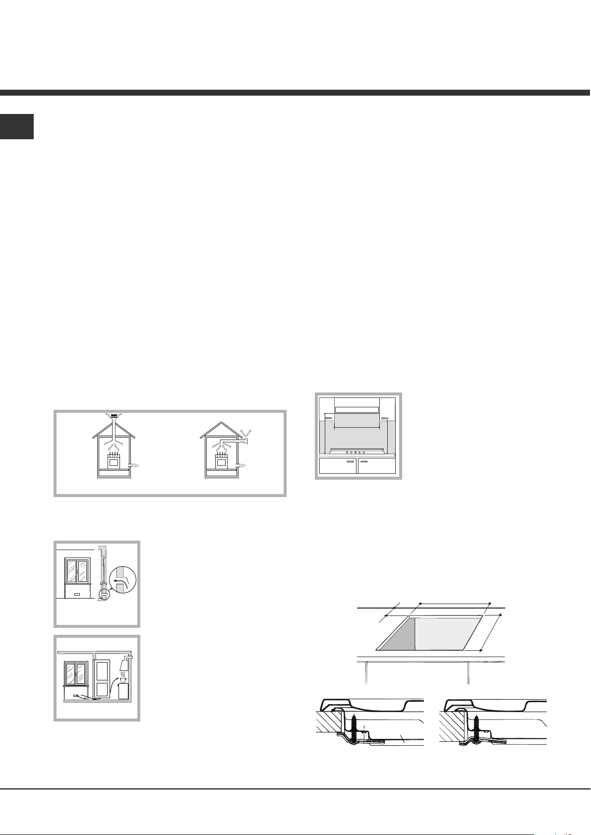
Examples of ventilation holes
for comburant air.
In a chimney stack or branched flue.
(exclusively for cooking appliances)
Directly to
the Outside
600mm min.
600mm min.
700mm min.
GB
! Before operating your new appliance please read this
instruction booklet carefully. It contains important
information for safe use, installation and care of the
appliance.
! Please keep these operating instructions for future
reference. Pass them on to possible new owners of the
appliance.
Positioning
! Keep packaging material out of the reach of children. It
can become a choking or suffocation hazard (see
Precautions and tips).
! The appliance must be installed by a qualified
professional according to the instructions provided.
Incorrect installation may cause harm to people and
animals or may damage property.
! This unit may be installed and used only in permanently
ventilated rooms in accordance with British Standard
Codes Of Practice: B.S. 6172 / B.S. 5440, Par. 2 and B.S.
6891 Current Editions. The following requirements must be
observed:
• The room must be equipped with an air extraction
system that expels any combustion fumes. This may
consist of a hood or an electric fan that automatically
• Liquid petroleum gas sinks to the floor as it is heavier
than air. Therefore, rooms containing LPG cylinders
must also be equipped with vents to allow gas to
escape in the event of a leak. As a result LPG
cylinders, whether partially or completely full, must not
be installed or stored in rooms or storage areas that are
below ground level (cellars, etc.). It is advisable to
keep only the cylinder being used in the room,
positioned so that it is not subject to heat produced by
external sources (ovens, fireplaces, stoves, etc. ) which
could raise the temperature of the cylinder above 50°C.
Fitting the appliance
Gas and mixed hobs are manufactured with type X
degree protection against overheating. The following
precautions must be taken when installing the hob:
• Kitchen cabinets adjacent to the appliance and taller
than the top of the hob must be at least 600 mm from
the edge of the hob.
• Hoods must be installed according to their relative
installation instruction manuals and at a minimum
distance of 650 mm from the hob.
• Place the wall cabinets adjacent to the hood at a
minimum height of 420 mm from
the hob (see figure).
starts each time the appliance is switched on.
• The room must also allow proper air circulation, as air is
needed for combustion to occur normally. The flow of
air must not be less than 2 m
per kW of installed power.
The air circulation system may
take air directly from the outside
by means of a pipe with an inner
cross section of at least 100
2
; the opening must not be
cm
vulnerable to any type of
blockages.
The system can also provide the
air needed for combustion
indirectly, i.e. from adjacent
rooms fitted with air circulation
tubes as described above.
However, these rooms must not
be communal rooms, bedrooms
or rooms that may present a fire hazard.
If the hob is installed beneath a
wall cabinet, the latter must be
situated at a minimum of 700 mm
above the hob (see figure).
• The installation cavity should have the dimensions
3
/h
indicated in the figure.
Fastening hooks are provided, allowing you to fasten
the hob to tops that are between 20 and 40 mm thick.
To ensure the hob is securely fastened to the top, we
recommend you use all the hooks provided.
555 mm
55 mm
475 mm
Hook fastening diagram
Hooking position Hooking position
for top H=20 mm for top H=30 mm
2
Page 3
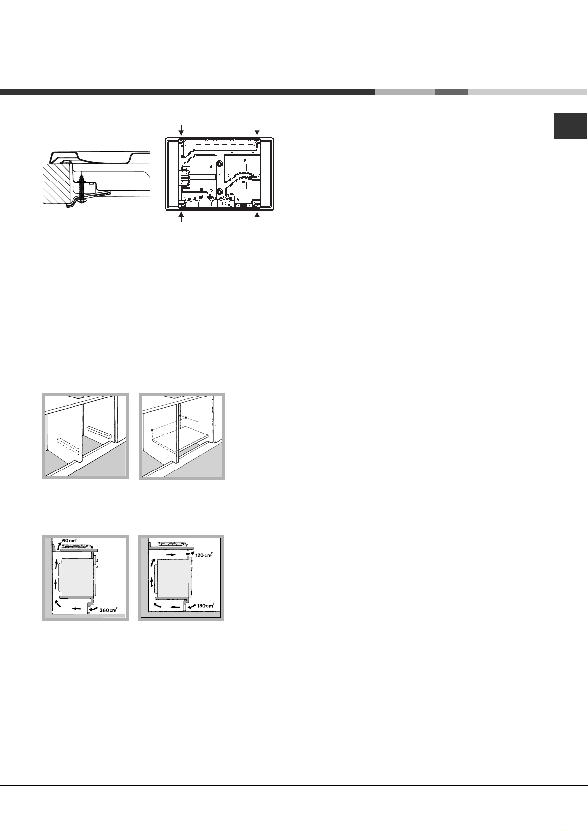
Front
560 mm
.
4
5
m
m
.
Hooking position Back
for top H=40 mm
! Use the hooks contained in the “accessory pack”
• Where the hob is not installed over a built-in oven, a
wooden panel must be installed as insulation. This
must be placed at a minimum distance of 20 mm from
the lower part of the hob.
Ventilation
To ensure adequate ventilation, the back panel of the
cabinet must be removed. It is advisable to install the
oven so that it rests on two strips of wood, or on a
completely flat surface with an opening of at least 45 x
560 mm (see diagrams).
When installing the cooktop above a built-in oven
without forced ventilation, ensure that there are air
inlets and outlets for ventilating the interior of the
cabinet adequately.
Electrical connection
Hobs equipped with a three-pole power supply cable are
designed to operate with alternating current at the voltage
and frequency indicated on the data plate (this is located
on the lower part of the appliance). The earth wire in the
cable has a green and yellow cover. If the appliance is to
be installed above a built-in electric oven, the electrical
connection of the hob and the oven must be carried out
separately, both for electrical safety purposes and to
make extracting the oven easier.
Connecting the supply cable to the mains
Install a standardised plug corresponding to the load
indicated on the data plate.
The appliance must be directly connected to the mains
using an omnipolar circuit-breaker with a minimum contact
opening of 3 mm installed between the appliance and the
mains. The circuit-breaker must be suitable for the charge
indicated and must comply with current electrical
regulations (the earthing wire must not be interrupted by the
circuit-breaker). The supply cable must not come into
contact with surfaces with temperatures higher than 50°C.
! The installer must ensure that the correct electrical
connection has been made and that it is compliant with
safety regulations.
Before connecting to the power supply, make sure that:
• The appliance is earthed and the plug is compliant with
the law.
• The socket can withstand the maximum power of the
appliance, which is indicated on the data plate.
• The voltage is in the range between the values
indicated on the data plate.
• The socket is compatible with the plug of the
appliance. If the socket is incompatible with the plug,
ask an authorised technician to replace it. Do not use
extension cords or multiple sockets.
! Once the appliance has been installed, the power supply
cable and the electrical socket must be easily accessible.
! The cable must not be bent or compressed.
! The cable must be checked regularly and replaced by
authorised technicians only (see Assistance).
! The manufacturer declines any liability should these
safety measures not be observed.
Gas connection
The appliance should be connected to the main gas
supply or to a gas cylinder in compliance with current
national regulations. Before carrying out the connection,
make sure the cooker is compatible with the gas supply
you wish to use. If this is not the case, follow the
instructions indicated in the paragraph “Adapting to
different types of gas.”
When using liquid gas from a cylinder, install a pressure
regulator which complies with current national regulations.
! Check that the pressure of the gas supply is consistent
with the values indicated in Table 1 (“Burner and nozzle
specifications”). This will ensure the safe operation and
longevity of your appliance while maintaining efficient
energy consumption.
Connection with a rigid pipe (copper or steel)
! Connection to the gas system must be carried out in
such a way as not to place any strain of any kind on the
appliance.
GB
3
Page 4
GB
There is an adjustable L-shaped pipe fitting on the
appliance supply ramp and this is fitted with a seal in
order to prevent leaks. The seal must always be replaced
after rotating the pipe fitting (seal provided with
appliance). The gas supply pipe fitting is a threaded 1/2
gas cylindrical male attachment.
Connecting a flexible jointless stainless steel pipe to a
threaded attachment
The gas supply pipe fitting is a threaded 1/2 gas
cylindrical male attachment.
These pipes must be installed so that they are never
longer than 2000 mm when fully extended. Once
connection has been carried out, make sure that the
flexible metal pipe does not touch any moving parts and
is not compressed.
! Only use pipes and seals that comply with current
national regulations.
Checking the tightness of the connection
! When the installation process is complete, check the
pipe fittings for leaks using a soapy solution. Never use a
flame.
Adapting to different types of gas
To adapt the hob to a different type of gas other than
default type (indicated on the rating plate at the base of
the hob or on the packaging), the burner nozzles should
be replaced as follows:
1. Remove the hob grids and slide the burners off their
seats.
2. Unscrew the nozzles using a 7 mm socket spanner,
and replace them with nozzles for the new type of gas
(see table 1 “Burner and nozzle characteristics”).
3. Reassemble the parts following the above procedure in
the reverse order.
4. Once this procedure is finished, replace the old rating
sticker with one indicating the new type of gas used.
Sticker are available from any of our Service Centres.
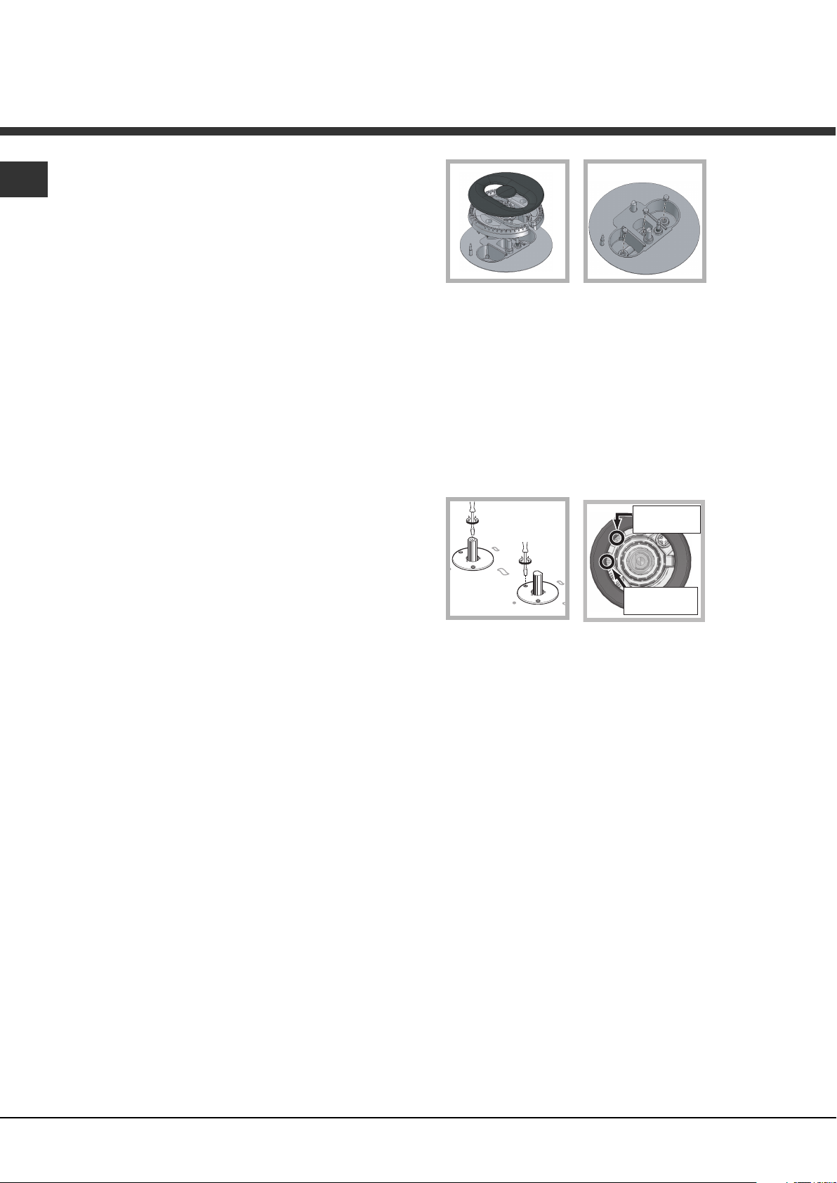
Replacing the nozzles on separate “double flame “
burners:
1. remove the grids and slide the burners from their
housings. The burner consists of 2 separate parts (see
figure);
2. unscrew the burers with a 7 mm wrench spanner. The
internal burner has a nozzle, the external burner has
two (of the same size). Replace the nozzle with models
suited to the new type of gas (see table 1).
3. replace all the components by repeating the steps in
reverse order.
• Adjusting the burners’ primary air :
Does not require adjusting.
• Setting the burners to minimum:
1. Turn the tap to the low flame position.
2. Remove the knob and adjust the adjustment screw,
which is positioned in or next to the tap pin, until the
flame is small but steady.
! In the event of single-control DRDA (DCDR) burners,
adjustment can be performed by intervening on the 2
screws located near the tap pin (see picture).
Total DRDA
(DCDR) burner
adjustment
Inner DRDA (DCDR)
burner adjustment
3. Having adjusted the flame to the required low setting,
while the burner is alight, quickly change the position of
the knob from minimum to maximum and vice versa
several times, checking that the flame does not go out.
4. Some appliances have a safety device (thermocouple)
fitted. If the device fails to work when the burners are
set to the low flame setting, increase this low flame
setting using the adjusting screw.
5. Once the adjustment has been made, replace the seals
on the by-passes using sealing wax or a similar
substance.
6. In the event of discrete-adjustment knobs with
LED visualisation, turn the knob to the minimum
power setting them remove it and intervene on the
adjustment screw located near the tap pin.
7. Minimum setting adjustment of the DRDA (DCDR)
burner with discrete adjustment and LED
visualisation:
• To adjust the outer ring, turn the knob anticlockwise to the minimum power position.
• To adjust the minimum power setting of the
inner ring, turn the knob clockwise to the minimum
power position.
• Remove the knob and intervene on the
adjustment screw located near the tap pin.
4
Page 5
! If the appliance is connected to liquid gas, the regulation
screw must be fastened as tightly as possible.
! Once this procedure is finished, replace the old rating
sticker with one indicating the new type of gas used.
Stickers are available from any of our Service Centres.
! Should the gas pressure used be different (or vary
slightly) from the recommended pressure, a suitable
pressure regulator must be fitted to the inlet pipe (in order
to comply with current national regulations).
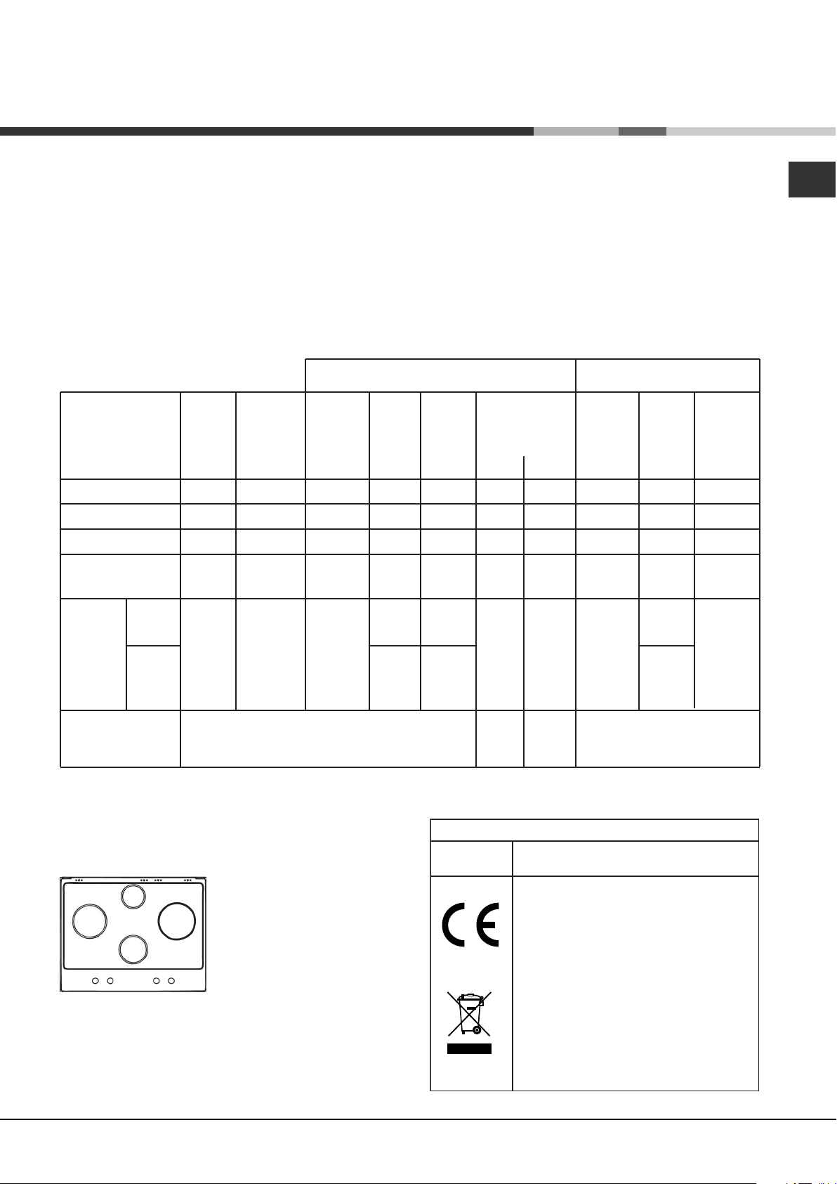
Burner and nozzle specifications (for 60 cm versions only)
Table 1 Liquid Gas Natural Gas
Burner Diameter Thermal Thermal By-pass Nozzle Flow* Thermal Nozzle Flow*
power power 1/100 1/100 (g/h) power 1/100 (l/h)
kW kW kW
(p.c.s.*) (p.c.s.*) (p.c.s.*)
(mm) Reduced Nominal (mm) (mm) *** ** Nominal (mm)
Reduced Fast (RR)
100
0.70
2.60
39
80
189
186
2.60
122 (H)
248
GB
Semi Fast (S)
Auxiliary (A)
Double flame
(DCDR internal) (1)
Double
flame (1)
Supply pressures
(1) For single-control DRDA (DCDR) burner only
* At 15°C and 1013 mbar - dry gas
** Propane P.C.S. = 50.37 MJ/Kg
*** Butane P.C.S. = 49.47 MJ/Kg
Natural P.C.S. = 37.78 MJ/m³
(DCDR
internal)
(DCDR
external
2 nozzle)
75
55
30 0,30 0,90 27 44 65 64 0,90 74 86
130 1,50 3,60
0.40
0.40
Nominal (mbar)
Minimum (mbar)
Maximum (mbar)
A
RR
DC
S
PK 640 RL GH AG
1.65
1.00
28
28
27 44
55 60x2 100x 2
64
50
DATA PLAT E
Electrical
connections
120
73
262 257 3,60
28-30
20
35
118
71
37
25
45
see data plate
This appliance conforms to the following
European Economic Community directives:
- 2006/95/EEC dated 12/12/06 (Low
Voltage) and subsequent amendments
- 2004/108/EEC dated 15/12/04
(Electromagnetic Compatibility) and
subsequent amendments
- 93/68/EEC dated 22/07/93 and
subsequent amendments.
- 2009/142/EEC dated 30/11/09 (Gas) and
subsequent amendments.
- 2002/96/EC and subsequent
amendments.
1.65
1.00
96 (Y)
79 (6)
74
157
95
343
20
17
25
5
Page 6

GB
Burner and nozzle specifications (for 75 cm versions only)
Table 1 Liquid Gas Natural Gas
Burner Diameter Thermal Thermal By-pass Nozzle Flow* Thermal Nozzle Flow*
power power 1/100 1/100 (g/h) power 1/100 (l/h)
kW kW kW
(p.c.s.*) (p.c.s.*) (p.c.s.*)
(mm) Reduced Nominal (mm) (mm) *** ** Nominal (mm)
Reduced Fast (RR)
Semi Fast (S)
Auxiliary (A)
Semi-Fishburner (SP)
Double Flame
(DCDR Internal) (2)
Double Flame
(DCDR External)
2 nozzle (2)
Double flame
(DCDR internal) (1)
Double
flame (1)
Supply pressures
(DCDR
internal)
(DCDR
external
2 nozzle)
100
75
55
—
30
130
30 0,30 0,90 27 44 65 64 0,90 69 86
130 1,50 4,60
0.70
0.40
0.40
0.70
0.40
1.50
Nominal (mbar)
Minimum (mbar)
Maximum (mbar)
2.60
1.65
1.00
1.50
0.90
4.10
39
28
28
39
28
61
27 44
55 70 x 2 113 x 2
80
64
50
60
44
70x2
189
120
73
109
65
298
334 329 5,00
28-30
20
35
186
118
71
107
64
293
37
25
45
2.60
1.65
1.00
1.50
0.90
4.10
122 (H)
96 (Y)
79 (6)
88
70
114x2
69
476
20
17
25
248
157
95
143
86
390
(1) For single-control DRDA (DCDR) burner only
(2) For dual-control DRDA (DCDR) burner only
* At 15°C and 1013 mbar - dry gas
** Propane P.C.S. = 50.37 MJ/Kg
*** Butane P.C.S. = 49.47 MJ/Kg
Natural P.C.S. = 37.78 MJ/m³
RR
DC SP
A
PK760RF GH AG
RR
DC
A
PK750RL GH AG
S
S
DC
S
A
PK741RQO GH AG
6
Page 7
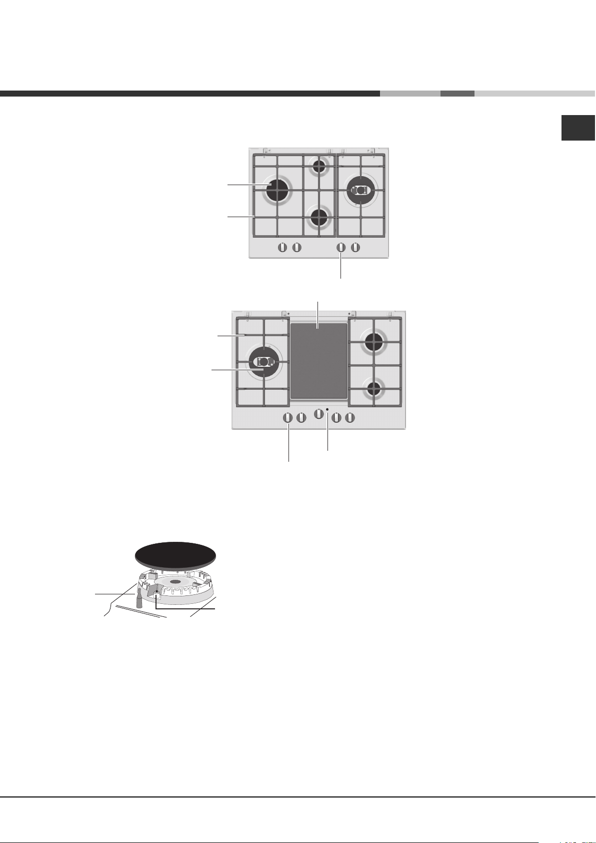
Description of the
appliance
Overall view
GB
GAS BURNERS
Support Grid for
COOKWARE
Control Knobs for
GAS BURNERS
CERAMIC GLASS MODULE *
Support Grid for
COOKWARE
GAS BURNERS
Control Knobs for
GAS BURNERS and
CERAMIC GLASS MODULE*
SAFETY
DEVICES *
• The INDICATOR LIGHT FOR CERAMIC GLASS
MODULE switches on whenever the selector knob
is moved from the ‘off’ position.
• GAS BURNERS differ in size and power. Use the
diameter of the cookware to choose the most
appropriate burner to cook with.
Ignition for
GAS BURNERS *
Indicator Light for
CERAMIC GLASS MODULE *
• GAS BURNER ignition* enables a specific burner
to be lit automatically.
• SAFETY DEVICE* stops the gas flow if the flame is
accidentally extinguished.
• Control Knobs for GAS BURNERS and CERAMIC
GLASS MODULE* adjust the power or the size of
the flame.
Only available on certain models.
*
7
Page 8
Start-up and use
GB
! The position of the corresponding gas burner or
electric hotplate* is shown on every knob.
Gas cooker hobs are equipped with discrete power
adjustment that allows for accurately adjusting the
flame to 5 different power levels. Thanks to this
system, gas hobs are also capable of guaranteeing
the same cooking results for each recipe, as the
optimal power level for the desired type of cooking
can be identified in an easier, more accurate way.
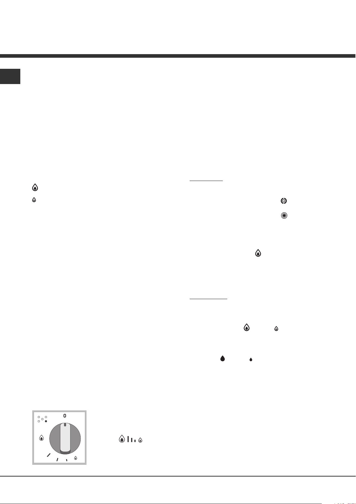
Gas burners
Each burner can be adjusted to one of the following
settings using the corresponding control knob:
• Off
Maximum
Minimum
To light one of the burners, hold a lit match or lighter
near the burner and, at the same time, press down
and turn the corresponding knob anti-clockwise to the
maximum setting.
Since the burner is fitted with a safety device, the
knob should be pressed for approximately 2-3
seconds to allow the automatic device keeping the
flame alight to heat up.
When using models with an ignition button, light the
desired burner pressing down the corresponding
knob as far as possible and turning it anticlockwise
towards the maximum setting.
! If a flame is accidentally extinguished, turn off the
control knob and wait for at least 1 minute before
trying to relight it.
To switch off the burner, turn the knob in a clockwise
direction until it stops (when reaches the “•” position).
Discrete flame adjustment
The selected burner can be adjusted - by means of
the knob - to 5 different power levels.
To shift between levels, simply turn the knob
towards the desired power level.
A click signals the passage from one power level to
the other.
The selected power level is
indicated by the
corresponding symbol
(symbols
hobs equipped with a
display, by the LEDs that turn
) and, on
on (5 = max. power; 1 = min. power). The system
guarantees accurate flame adjustment and uniform
cooking results by facilitating selection of the
desired power level.
The "double-flame" burner
This gas burner consists of two concentric flame
rings that can operate jointly or independently (in
case of dual-control only).
As the burner is fitted with a safety device, the
knob should be pressed down for approximately 2-3
seconds until the device keeping the flame
automatically alight heats up.
Dual control:
Each ring comprising the burner has its own control
knob:
The knob marked with the symbol
outer ring.
The knob marked with the symbol
inner ring.
To activate any one of the two rings, press the
corresponding knob and turn it anti-clockwise to the
maximum power setting
In order to use the double-flame burner to its full
potential, avoid simultaneously setting the inner
ring to minimum power and the outer ring to
maximum power.
Single control:
The rings comprising the burner are activated
through a single control knob.
To simultaneously turn on both rings, position the
knob on the symbol
and turn the knob anti-clockwise.
To turn on the inner ring only, position the knob on
the symbol
the knob clockwise.
(to switch modes, it is necessary to switch off the
burner).
To switch off the burner, press and turn the knob
clockwise until it stops (when it reaches the "•"
position).
Ceramic Glass Module*
This cooktop is fitted with dual-ring radiant heating
elements located beneath the glass. It is possible to
turn on only the circular part of the elemement
(identified by the letter "A") or the cooking surface
Only available on certain models.
*
(max.) - (min.) then press and turn
.
(max.) - (min.) then press
controls the
controls the
8
Page 9
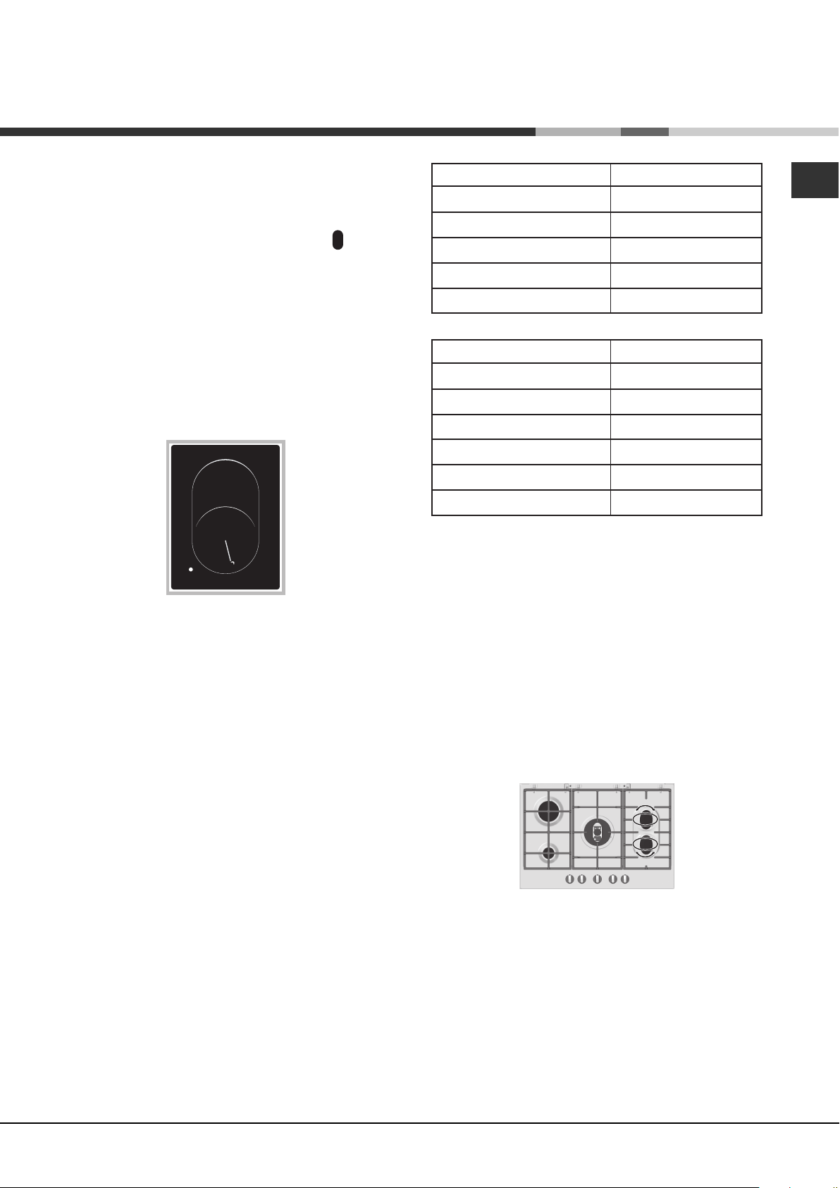
can be enlarged by turning on both "A" and "B". To
turn only the circular "A" element, simply turn the
knob in the clockwise direction to any one of the 12
available settings. To add the "B" section, turn the
knob to setting 12 and then click it into the
setting. Then proceed by turning the knob in the
counter-clockwise direction to one of the 12
settings.
The figure shows the heating zones, which become
red when the element is turned on.
A. Circular heating zone;
B.Extended heating zone;
C.Indicator light to show when the cooking zone is
above 60°C, even after the heating element has
been turned off.
B
A
O
val R
C
ing
When the knob is on any of the settings other than
"Off", the Indicator Light for Ceramic Glass Module
comes on.
Burner
Rapid (R)
Semi-Rapid (S)
Auxiliary (A)
Double Flame (DCDR internal)
Double Flame (DCDR external)
Ø Cookware Diameter (cm)
24 - 26
16 - 20
10 - 14
10 - 14
24 - 26
Pans to be used on 60 cm hobs
Burner
Reduced Rapid (RR)
Semi-Rapid (S)
Auxiliary (A)
Semi-Fishburner (SP)
Double Flame (DCDR internal)
Double Flame (DCDR external)
Ø Cookware Diameter (cm)
24 - 26
16 - 20
10 - 14
16 - 20
10 - 14
26 - 28
Pans to be used on 75 cm hobs
! On the models supplied with a reducer shelf,
remember that this should be used only for the Double
flame internal (DCDR internal) burner when you use
casserole dishes with a diameter under 12 cm.
To identify the type of burner, refer to the designs in
the section entitled, "Burner and Nozzle
Specifications".
GB
Practical advice on using the burners
To ensure the burners operate efficiently:
• Use appropriate cookware for each burner (see
table) so that the flames do not extend beyond the
bottom of the cookware.
• Always use cookware with a flat base and a cover.
• When the contents of the pan reach boiling point,
turn the knob to minimum.
Only available on certain models.
*
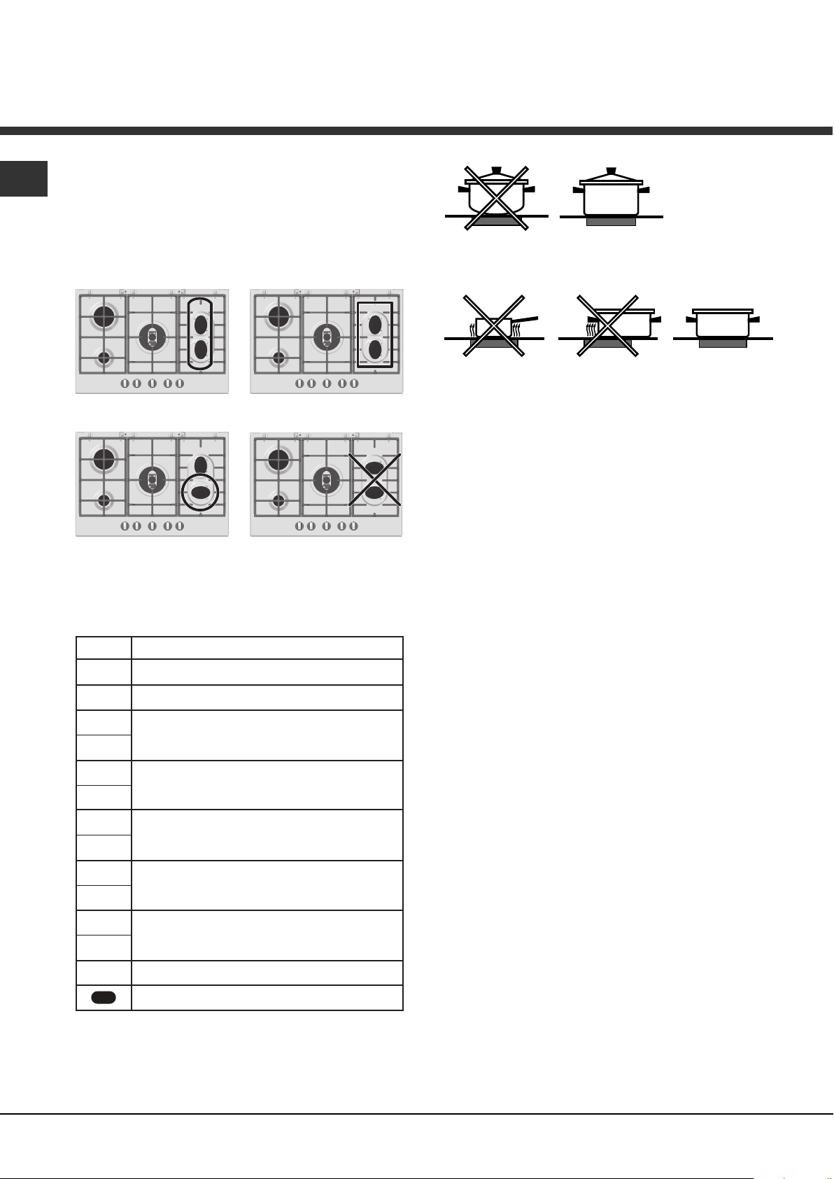
Practical Advice on Using the Half Fish-Kettle
Burner *
The two "Half Fish-Kettle" burners, are eliptic in form
and can be turned up to 90°. This makes the cooktop
more flexible in terms of how it can be used.
To turn the two burners 90°, proceed as follows:
• Make sure that the burners are cool;
• Lift the burner completely out of its housing;
• Replace it in its housing in the position desired;
• Make sure that the burners are positioned
correctly before use.
In addition, the two burners can be used in tandem
or speartely with cookware of different shapes and
sizes:
• Double burner for a fish-kettle or oval cookware
(Fig.A).
9
Page 10
GB
• Double burner for a griddle or rectangular/square
cookware with minimum dimensions of 28x28 cm
(Fig.B)
• Single burner for medium size cookware (diameter
of 16-20 cm) (Fig.C).
• NEVER use the double burner in the configuration
represented in figure D.
Fig. A Fig. B
Fig. C Fig. D
Practical Advise on Using the Ceramic
Glass Module*
Set.
Radiant Burner
0
Off.
1
To melt butter and chocolate.
2
To heat liquids.
3
• Always use pans with a diameter that is large
enough to cover the hotplate fully, in order to use
all the available heat.
• Make sure that the bottom of the cookware is
always dry and clean to guarantee correct
adherence and long life, not only for the cooking
zones but also for the cookware itself.
• Avoid using the same cookware that is used on
gas burners: the heat concentration on gas
burners may deform the base of the pan, causing
it not to adhere correctly.
• Never leave a cooking zone on without cookware
on it because as it heats up and rapidly reaches
the maximum level, which could damage the
heating elements.
! The glue used for sealing the glass may leave
greasy residues. We recommend removing them
with a non-abrasive cleaning product prior to
operating the appliance. During the first few hours of
operation, there may be a smell of rubber that will
soon disappear.
4
For creams and sauces.
5
6
For cooking at the boiling point.
7
8
For Roasts.
9
10
11
12
For boiling large pieces of meat.
For frying.
For utilising both cooking areas.
To obtain the best results from your hob:
• Use flat-bottomed pans to ensure that they adhere
to the cooking zone perfectly.
10
Page 11
Precautions and tips
! This appliance has been designed and manufactured
in compliance with international safety standards. The
following warnings are provided for safety reasons and
must be read carefully.
General safety
• This is a class 3 built-in appliance.
• Gas appliances require regular air exchange to
maintain efficient operation. When installing the
hob, follow the instructions provided in the
paragraph on “Positioning” the appliance.
• These instructions are only valid for the countries
whose symbols appear in the manual and on the
serial number plate.
• The appliance was designed for domestic use inside
the home and is not intended for commercial or
industrial use.
• The appliance must not be installed outdoors, even in
covered areas. It is extremely dangerous to leave the
appliance exposed to rain and storms.
• Do not touch the appliance with bare feet or with wet
or damp hands and feet.
• The appliance must be used by adults only for the
preparation of food, in accordance with the
instructions outlined in this booklet. Any other
use of the appliance (e.g. for heating the room)
constitutes improper use and is dangerous. The
manufacturer may not be held liable for any
damage resulting from improper, incorrect and
unreasonable use of the appliance.
• Ensure that the power supply cables of other
electrical appliances do not come into contact with
the hot parts of the oven.
• The openings used for ventilation and dispersion of
heat must never be covered.
• Always make sure the knobs are in the “”/“
position when the appliance is not in use.
• When unplugging the appliance always pull the plug
from the mains socket, do not pull on the cable.
• Never carry out any cleaning or maintenance work
without having detached the plug from the mains.
• In case of malfunction, under no circumstances
should you attempt to repair the appliance yourself.
Repairs carried out by inexperienced persons may
cause injury or further malfunctioning of the
appliance. Contact a Service Centre (see
Assistance).
• Always make sure that pan handles are turned
towards the centre of the hob in order to avoid
accidental burns.
• Do not close the glass cover (if present) when the gas
burners or electric hotplates are still hot.
”
• Do not leave the electric hotplate switched on without
a pan placed on it.
• Do not use unstable or deformed pans.
• Remove any liquid from the lid before
opening it.
• Prevent children and the disabled from coming into
contact or having access at the ceramic glass
cooking surface (if present) immediately before and
after use, as the cooking surface will remain hot for at
least a half hour after being turned off;
• Contact service centers authorized by the
manufacturer in the event the ceramic glass cooking
surface breaks.
• It is recommended that you follow the guidelines
below:
• Disconnect the appliance from the electrical supply in
the event the ceramic glass cooking surface
breakds.
• The appliance should not be operated by people
(including children) with reduced physical, sensory or
mental capacities, by inexperienced individuals or by
anyone who is not familiar with the product. These
individuals should, at the very least, be supervised
by someone who assumes responsibility for their
safety or receive preliminary instructions relating to
the operation of the appliance.
• Do not let children play with the appliance.
• The appliance is not intended to be operated by
means of an external timer or separate remotecontrol system.
Disposal
• When disposing of packaging material: observe local
legislation so that the packaging may be reused.
• The European Directive 2002/96/EC on Waste
Electrical and Electronic Equipment (WEEE), requires
that old household electrical appliances must not be
disposed of in the normal unsorted municipal waste
stream. Old appliances must be collected separately
in order to optimise the recovery and recycling of the
materials they contain and reduce the impact on
human health and the environment. The crossed out
“wheeled bin” symbol on the product reminds you of
your obligation, that when you dispose of the
appliance it must be separately collected.
Consumers may take their old appliance to public
waste collection areas, other communal collection
areas, or if national legislation allows return it to a
retailer when purchasing a similar new product.
All major household appliance manufacturers are
active in the creation of systems to manage the
collection and disposal of old appliances.
GB
11
Page 12
Maintenance and care
GB
Switching the appliance off
Disconnect your appliance from the electricity supply
before carrying out any work on it.
Cleaning the appliance
! Do not use abrasive or corrosive detergents such as
stain removers, anti-rust products, powder detergents
or sponges with abrasive surfaces: these may scratch
the surface beyond repair.
! Never use steam cleaners or pressure cleaners on
the appliance.
• It is usually enough to wash the hob with a damp
sponge and dry it with absorbent kitchen roll.
• The removable parts of the burners should be
washed frequently with warm water and soap and
any burnt-on substances removed.
• For hobs which ligth automatically, the terminal part
of the electronic instant lighting devices should be
cleaned frequently and the gas outlet holes should
be checked for blockages.
• Stainless steel can be marked by hard water that
has been left on the surface for a long time, or by
aggressive detergents containing phosphorus.
After cleaning, rinse and dry any remaining drops
of water.
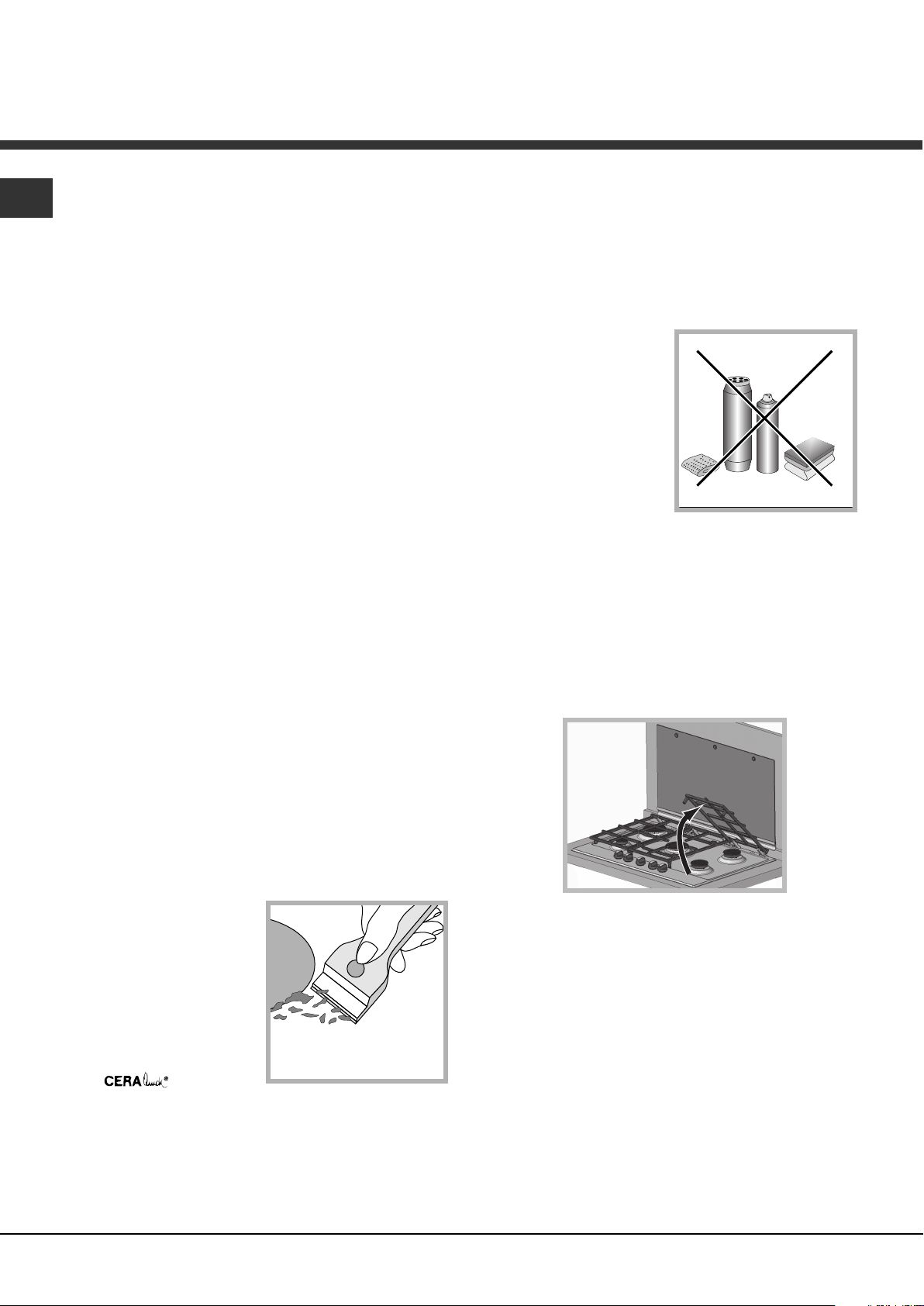
items, objects made of synthetic material, sugar
or foods with a high sugar content that have
melted onto the surface must be removed
immediatley with a scraper while the cooking
surface is still hot. Special cleaning products for
ceramic glass surfaces form a transparent
protective layer which fights diry buildup. This
also protects the surface from damage caused by
food with a high
sugar content. Do
not use abrasive
sponges or cleaning
products under any
circumstances. This
holds true for
chemically
aggressive cleaners,
like oven sprays and
stain removers.
! It is not necessary to remove the pan supports in
order to clean the hob surface. Thanks to the
support system, simply lift and hold the pan
supports or rotate them until they rest against a rear
support.
Do not place the hot grids on top of the glass
cover (if applicable), otherwise the rubber plugs
on the glass may be damaged.
• Before using the ceramic glass module, the surface
must be cleaned, using a damp cloth to remove
dust or food residues. The ceramic glass surface
should be cleaned regularly with a soultion of warm
water and a nonabrasive detergent.
Periodically, special
products will need to
be used to clean the
surface. First,
remove all food
buildup or grease
with a cleaning
scraper, e.g.
(not
supplied.
Clean the cooking surface when it is still warm with
a suitable cleaning product (such as the one in the
Solutions product line available from any AfterSales Service Centre) and paper towels. Then rub
with a damp cloth and dry. Aluminum foil, plastic
12
Gas tap maintenance
Over time, the taps may become jammed or difficult
to turn. If this happens, the tap must be replaced.
! This procedure must be performed by a qualified
technician authorised by the manufacturer.
Page 13

Troubleshooting
It may happen that the appliance does not function properly or at all. Before calling the service centre for
assistance, check if anything can be done. First, check to see that there are no interruptions in the gas and
electrical supplies, and, in particular, that the gas valves for the mains are open.
GB
Problem
The burner does not light or the flame is not
even around the burner.
The flame dies in models with a safety device.
The burner does not remain lit when set to
minimum.
The cookware is unstable.
If, despite all these checks, the hob does not function properly and the problem persists, call the nearest
Customer Service Centre. Please have the following information handy:
• The appliance model (Mod.).
• The serial number (S/N).
This information can be found on the data plate located on the appliance and/or on the packaging.
Possible causes/Solution
• The gas holes on the burner are clogged.
• All the movable parts that make up the burner are
mounted correctly.
• There are draughts near the appliance.
• You pressed the knob all the way in.
• You keep the knob pressed in long enough to activate the
safety device.
• The gas holes are not blocked in the area corresponding
to the safety device.
• The gas holes are not blocked.
• There are no draughts near the appliance.
• The minimum setting has been adjusted properly.
• The bottom of the cookware is perfectly flat.
• The cookware is positioned correctly at the centre of the
burner.
• The pan support grids have been positioned correctly.
! Never use unauthorised technicians and never accept replacement parts which are not original.
13
Page 14

Manual de
ES
instrucciones
GB
English,1
ES
Español, 14
PK 741 RQO GH AG
PK 750 RL GH AG
PK 640 RL GH AG
PK 760 RF GH AG
PT
Português, 29
ENCIMERA
Sumario
Instalación, 15-21
Colocación
Conexión eléctrica
Conexión gas
Características de los quemadores e inyectores
Placa de características
Descripción del aparato, 22
Vista de conjunto
Puesta en funcionamiento y uso, 23-25
Consejos prácticos para el uso de los quemadores
Consejos prácticos para el uso de la placa
Vitrocerámica
Precauciones y consejos, 26
Seguridad general
Eliminación
Mantenimiento y cuidados, 27
Cortar la corriente eléctrica
Limpiar el aparato
Mantenimiento de las llaves de gas
Placa de características
Anomalías y soluciones, 28
14
Page 15

Instalación
Aumento de la ranura entre
puerta y suelo
Habitación
adyacente
Habitación
por ventilar
A
Ejemplos de aperture
de ventilación
para aire comburente
En chimenea o tubo de chimenea ramificado
(reservado a los aparatos de cocción)
Directamente
al externo
600mm min.
600mm min.
700mm min.
! Es importante conservar este manual para poder
consultarlo en todo momento. En caso de venta, de cesión
o de mudanza, verifique que permanezca junto al aparato
para informar al nuevo propietario sobre su funcionamiento
y sobre las advertencias correspondientes.
! Lea atentamente las instrucciones: contienen importante
información sobre la instalación, el uso y la seguridad.
Colocación
! Los embalajes no son juguetes para niños y se deben
eliminar respetando las normas para la recolección de
residuos (ver Precauciones y consejos).
! La instalación se debe realizar siguiendo estas
instrucciones y por personal profesionalmente calificado.
Una instalación incorrecta puede producir daños a
personas, animales o cosas.
! Este aparato puede ser instalado y funcionar sólo en
lugares ventilados permanentemente, de acuerdo a las
prescripciones de l’Orden de 29.03.1974. Deben ser
observados los siguentes requisitos:
• El ambiente debe poseer un sistema de descarga de los
humos de la combustión al exterior, utilizando una
campana o un electroventilador que entre
automáticamente en funcionamiento cada vez que se
enciende el aparato.
• El ambiente debe poseer un sistema que permita la
entrada del aire necesario para una combustión normal.
El caudal de aire necesario para la combustión no debe
ser inferior a 2 m
instalada.
3
/h por cada kilovatio (kW) de potencia
El sistema puede tomar aire del
exterior del edificio a través de un
2
conducto de 100 cm
, como
mínimo, de sección útil de modo
que no pueda ser obstruido
accidentalmente.
• Los gases de petróleo licuados, más pesados que el aire,
se depositan en las partes más bajas. Por lo tanto, los
ambientes que contienen botellas de GPL deben tener
aberturas hacia el exterior para permitir la evacuación
desde abajo de eventuales escapes de gas. Además, las
botellas de GPL, vacías o parcialmente llenas, no deben
ser instaladas o depositadas en ambientes o espacios a un
nivel más bajo del suelo (sótanos, etc.) Es conveniente
conservar en el ambiente sólo la botella que se está
utilizando, colocada de modo que no quede expuesta a la
acción directa de fuentes de calor (hornos, chimeneas,
estufas, etc.) capaces de llevarla a temperaturas superiores
a 50°C.
Empotramiento
Las encimeras a gas y mixtas están fabricadas con un grado de
protección contra calentamientos excesivos de tipo X, y por lo
tanto, es posible su instalación al lado de muebles cuya altura no
supere la de la superficie de trabajo. Para una correcta instalación
de la encimera se deben observar las siguientes precauciones:
• Los muebles situados a un costado, cuya altura supere la
de la superficie de trabajo, deben estar situados a 600
mm., como mínimo, del borde de la misma.
• Las campanas deben ser instaladas de acuerdo con los
requisitos establecidos en los manuales de instrucción
de las mismas, siempre manteniendo una distancia
mínima de 650 mm.
• Coloque los armarios de pared adyacentes a la campana
a una altura mínima desde la superficie de trabajo, de
420 mm. (ver la figura).
Siempre que la encimera se
instale debajo de un armario de
pared, éste último deberá
mantener una distancia mínima de
la superficie de trabajo de 700
mm. (ver la figura).
• El espacio para el mueble deberá tener las dimensiones
indicadas en la figura. Se han previsto ganchos de fijación
que permiten fijar la encimera a superficies de 20 a 40 mm.
de espesor. Para un buena fijación de la encimera, es
aconsejable usar todos los ganchos que se suministran.
555 mm
ES
También puede hacerlo de
manera indirecta, desde
ambientes adyacentes que
posean un conducto de
ventilación hacia el exterior, como
se describe más arriba, y que no
sean partes en común del
inmueble, ambientes con peligro
de incendio o dormitorios.
55 mm
475 mm
15
Page 16

ES
560 mm.
4
5
m
m
.
Esquema de fijación de los ganchos
Posición del gancho para Posición del gancho para
superficies
Posición del gancho para Atrás
superficies
H=20mm superficies H=30mm
Adelante
H=40mm
! Use los ganchos contenidos en el “paquete de
accesorios”
• Cuando la encimera no se instale sobre un horno
empotrado, es necesario introducir un panel de madera
como aislamiento. El mismo deberá colocarse a una
distancia mínima de 20 mm. de la pared inferior de la
encimera.
Aireación
Para garantizar una buena aireación es necesario eliminar
la pared posterior del hueco para el horno. Es preferible
instalar el horno apoyado sobre dos listeles de madera o
sobre una superficie continua que tenga una abertura de
45 x 560 mm. como mínimo (ver las figuras).
Cuando se trate de instalación sobre un horno
empotrable sin ventilación forzada de refrigeración,
para permitir una adecuada ventilación en el interior
del mueble, se garantizan tomas de aire de entrada
y de salida.
Conexión eléctrica
Las encimeras que poseen cable de alimentación tripolar,
se fabrican para funcionar con corriente alterna, a la
tensión y frecuencia de alimentación indicadas en la placa
de características (ubicada en la parte inferior de la
encimera). El conductor de puesta a tierra del cable se
distingue por los colores amarillo-verde. Cuando se
realiza la instalación sobre un horno empotrado, la
conexión eléctrica de la encimera y la del horno se deben
realizar por separado, ya sea por razones de seguridad
eléctrica, como para facilitar la eventual extracción del
horno.
Conexión del cable de alimentación eléctrica a la red
Instale en el cable un enchufe normalizado para la carga
indicada en la placa de características.
En el caso de conexión directa a la red, es necesario
interponer entre el aparato y la red, un interruptor omnipolar
con una distancia mínima entre los contactos de 3 mm.,
dimensionado para esa carga y que responda a las normas
vigentes (el conductor de tierra no debe ser interrumpido
por el interruptor). El cable de alimentación eléctrica se
debe colocar de modo tal que no alcance en ningún punto
una temperatura que supere en 50°C la temperatura
ambiente.
! El instalador es responsable de la correcta conexión
eléctrica y del cumplimiento de las normas de seguridad.
Antes de efectuar la conexión verifique que:
• la toma tenga conexión a tierra y que sea conforme con
la ley;
• la toma sea capaz de soportar la carga máxima de
potencia de la máquina indicada en la placa de
características;
• la tensión de alimentación eléctrica esté comprendida
dentro de los valores indicados en la placa de
características;
• la toma sea compatible con el enchufe del aparato. Si no
es así, sustituya la toma o el enchufe; no utilice
prolongaciones ni conexiones múltiples.
! Una vez instalado el aparato, el cable eléctrico y la toma
de corriente deben ser fácilmente accesibles.
! El cable no debe sufrir pliegues ni compresiones.
! El cable debe ser revisado periódicamente y sustituido
sólo por técnicos autorizados (ver Asistencia).
! La empresa declina toda responsabilidad cuando estas
normas no sean respetadas.
Conexión de gas
La conexión del aparato a la tubería o a la botella de gas se
deberá efectuar de acuerdo a lo prescripto por las Normas
Nacionales vigentes, sólo después de haber verificado que
el mismo está regulado para el tipo de gas con el cual será
alimentado. Si no es así, realice las operaciones indicadas
16
Page 17

en el párrafo “Adaptación a los distintos tipos de gas”.
En el caso de alimentación con gas líquido, desde
botella, utilice reguladores de presión conformes con las
Normas Nacionales vigentes.
! Para un funcionamiento seguro, un adecuado uso de la
energía y una mayor duración del aparato, verifique que la
presión de alimentación cumpla con los valores indicados
en la tabla 1 “Características de los quemadores e
inyectores”.
Conexión con tubo rígido (cobre o acero)
! La conexión a la red de gas se debe efectuar de modo
que no provoque esfuerzos de ningún tipo al aparato.
En el tubo de alimentación del aparato se encuentra una
unión en “L” orientable, cuya estanqueidad está asegurada
por una junta. Si resultara necesario girar la unión, sustituya
siempre la junta estanca (suministrada con el aparato). La
unión de entrada de gas al aparato es roscada 1/2 gas
macho cilíndrico.
Conexión con tubo flexible de acero inoxidable de pared
continua con uniones roscadas
La unión de entrada de gas al aparato es roscada 1/2 gas
macho cilíndrico.
La colocación de dichos tubos se debe efectuar de modo
tal que su longitud, en condiciones de máxima extensión,
no sea mayor que 2000 mm. Una vez realizada la conexión,
verifique que el tubo metálico flexible no permanezca en
contacto con partes móviles o no quede aplastado.
! Utilice exclusivamente tubos y juntas estancas conformes
a la Normas Nacionales en vigencia.
Control de la estanqueidad
! Finalizada la instalación, controle la perfecta estanqueidad
de todas las uniones utilizando una solución jabonosa pero
nunca una llama.
Adaptación a los distintos tipos de gas
Para adaptar la encimera a un tipo de gas diferente de
aquel para el que fue fabricada (indicado en la etiqueta
fijada en la parte inferior de la encimera o en el embalaje),
es necesario sustituir los inyectores de los quemadores
efectuando las siguientes operaciones:
1. quite las parrillas de la encimera y extraiga los
quemadores.
2. desenrosque los inyectores utilizando una llave tubular
de 7mm. y sustitúyalos por los que se adapten al nuevo
tipo de gas (ver tabla 1 “Características de los
quemadores e inyectores”).
3. vuelva a colocar las piezas realizando las operaciones
en sentido contrario.
4. al finalizar la operación, sustituya la anterior etiqueta de
calibrado con la correspondiente al nuevo gas que se va
a utilizar, disponible en nuestros Centros de Asistencia
Técnica.
Sustitución de los picossen el quemador “doble
llama” independente:
• sacar las rejillas y quitar los quemadores de sus
sedes. El quemador está compuesto de 2 partes
separados (ver Fig. E y Fig. F)
• destornillar los picos, sirviéndose de una llave de tubo
de 7 mm. El quemador interno tiene un pico, el
quemador externo tiene dos (del mismo tamaño).
Reemplazar los picos por los que se adapten al nuevo
tipo de gas (ver tabla 1).
• Volver a colocar todos los componentes en sus
respectivas posiciones, efectuando las operaciones
inversas, respecto a la secuencia arriba indicada.
• Regulación de aire principal de los quemadores
Los quemadores no necesitan de ninguna regulación de
aire principal.
• Regulación de los mínimos
1. Lleve la llave hasta la posición de mínimo;
2. Quite el mando y accione el tornillo de regulación situado
en el interior o al costado de la varilla de la llave hasta
conseguir una pequeña llama regular.
! En el caso del quemador DCDR monomando, la
regulación se debe realizar con los 2 tornillos
ubicados al costado de la varilla del grifo (ver la
figura).
Regulación
DCDR total
Regulación
DCDR interno
3. Verifique que girando rápidamente el mando desde la
posición de máximo hasta la de mínimo, no se
apaguen los quemadores.
4. En los aparatos provistos del dispositivo de seguridad
(termopar), si dicho dispositivo no funcionara con los
quemadores al mínimo, aumente la capacidad de los
mínimos utilizando para ello el tornillo de regulación.
5. Una vez efectuada la regulación, vuelva a colocar los
precintos ubicados en los by-pass con lacre o un
material equivalente.
6. En el caso de mandos con regulación discreta y
visualización con led, coloque el mando en la
ES
17
Page 18

ES
posición de mínimo, luego extraiga el mando y
trabaje con el tornillo de regulación ubicado al
costado de la varilla del grifo.
7. Regulación de los mínimos del quemador DCDR
con regulación discreta y visualización con led:
• para regular la corona externa, gire el mando
en sentido antihorario hasta la posición de
mínimo;
• para regular el mínimo de la corona interna,
gire el mando en sentido horario hasta la posición
de mínimo;
• extraiga el mando y trabaje con el tornillo de
regulación ubicado al costado de la varilla del
grifo.
! En el caso de ga
s líquido, el tornillo de regulación
deberá enroscarse a fondo.
! Al finalizar la operación, sustituya la anterior etiqueta de
calibrado con la correspondiente al nuevo gas que se va
a utilizar, disponible en nuestros Centros de Asistencia
Técnica.
! Cuando la presión del gas utilizado sea distinta de la
prevista (o variable), es necesario instalar, en la tubería de
entrada, un regulador de presión conforme con las
Normas Nacionales en vigencia.
18
PLACA DE CARACTERÍSTICAS
Conexiones
eléctricas
ver placa de características
Este aparato es conforme con las
siguientes Normas Comunitarias:
- 2006/95/CEE del 12/12/06 (Baja
Tensión) y posteriores modificaciones
- 2004/108/CEE del 15/12/04
(Compatibilidad Electromagnética) y
posteriores modificaciones
- 93/68/CEE del 22/07/93 y posteriores
modificaciones.
- 2009/142/CEE del 30/11/09 (Gas) y
posteriores modificaciones.
- 2002/96/CEE y posteriores
modificaciones successives.
Page 19

Presión de trabajo para Gas Licuado 280 mm c.a
Características de los quemadores e inyectores (sólo modelo PK 640 R L GH AG)
Presión de trabajo para Gas Natural 180 mm c.a - Preparado para GN convertible a GPL
ES
HORNALLA
AUXILAR 1 1,00 860 50 860 79
SEMIRÁPIDO
RÁPIDO 1 2,60 2236 86 2236 116
Doble
llama
(1)
TOTAL 6 8,85 7610 - 7610 Tension de alimentacion 220-240 V~ 50-60Hz
Potencia: 0,6 W
INDUSTRIA ITALIANA
Importador: Indesit Argentina S.A.
(1) Sólo para DCDR monomando
IMPORTANTE: NO INSTALAR EN LUGARES SIN VENTILACION PERMANENTE
ESTE ARTEFACTO DEBE SER INSTALADO, DE ACUERDO CON LAS NORMASY REGLAMENTACIONES EN
VIGENCIA, FOR UN INSTALADOR MATRICULADO
CONSULTAR LAS INSTRUCCIONES ANTES DE INSTALAR Y UTILIZAR ESTE ARTEFACTO
AV.EDUARDO MANDERO 900 PISO 18 BUENOS AIRES; TEL. 011-4131-1513
Este artefacto esta preparado para trabajar con gas natural 18mb para gas natural. Se provee el juego de inyectores
para realizar el cambio de tipo de gas.
Sr. Instalador: en el caso de cambio de tipo de gas, sirvase aclararlo.
Tipo de gas: NATURAL/LICUADO (tache lo que no corrisponde)
(DCDR
Interno)
(DCDR
Externo
2 pico.)
N°
IN Y
1 1,65 1419 64 1419 106
3 3,60 3095
KW KCAL/H Inyector
GAS LICUADO GAS NATURAL
KW KCAL/H Inyector 1/100 (mm)
1/100 (mm)
1,00
1,65
2,60
44
3,60
60 x2 94 x2
8,85
Clase del artefacto: 3
Categoria de gas: II2H3B/P
Aprobado bajo norma:
NAG 312
3095
74
A
RR
DC
S
PK 640 RL GH AG
19
Page 20

ES
Características de los quemadores e inyectores (sólo modelo PK 741 RQO GH AG)
Presión de trabajo para Gas Natural 180 mm c.a - Preparado para GN convertible a GPL
Presión de trabajo para Gas Licuado 280 mm c.a
HORNALLA
N°
IN Y
KW KCAL/H Inyector
AUXILAR 1 1,00 860 50 860 79
SEMIRÁPIDO
Doble llama
(DCDR Interno) (2)
Doble llama
(DCDR Externo)
2 Pico (2)
1
1,65 1419 64 1419 106
144 70
4,60 3956
2
TOTAL 5 7,25 6235 - 6579 Tension de alimentacion 220-240 V~ 50-60Hz
Potencia: 2000 W
INDUSTRIA ITALIANA
Importador: Indesit Argentina S.A.
(2) Sólo para DCDR doble comando
IMPORTANTE: NO INSTALAR EN LUGARES SIN VENTILACION PERMANENTE
ESTE ARTEFACTO DEBE SER INSTALADO, DE ACUERDO CON LAS NORMASY REGLAMENTACIONES EN
VIGENCIA, FOR UN INSTALADOR MATRICULADO
CONSULTAR LAS INSTRUCCIONES ANTES DE INSTALAR Y UTILIZAR ESTE ARTEFACTO
AV.EDUARDO MANDERO 900 PISO 18 BUENOS AIRES; TEL. 011-4131-1513
Este artefacto esta preparado para trabajar con gas natural 18mb para gas natural. Se provee el juego de inyectores
para realizar el cambio de tipo de gas.
Sr. Instalador: en el caso de cambio de tipo de gas, sirvase aclararlo.
Tipo de gas: NATURAL/LICUADO (tache lo que no corrisponde)
GAS LICUADO GAS NATURAL
KW KCAL/H Inyector 1/100 (mm)
1/100 (mm)
1,00
1,65
5,00
4300
70 x2
7,65
Clase del artefacto: 3
Categoria de gas: II2H3B/P
Aprobado bajo norma:
NAG 312
114 x2
Características de los quemadores e inyectores (sólo modelo PK 750 RL GH AG)
Presión de trabajo para Gas Natural 180 mm c.a - Preparado para GN convertible a GPL
Presión de trabajo para Gas Licuado 280 mm c.a
HORNALLA
N°
IN Y
KW KCAL/H Inyector
AUXILAR 1 1,00 860 50 860 79
SEMIRÁPIDO
RÁPIDO 1 2,60 2236 86 2236 116
(DCDR
Doble
llama
(1)
Interno)
(DCDR
Externo
2 pico.)
2
1,65 1419 64 1419 106
1
4,60 3956
2
TOTAL 7 11,50 9890 - 10234 Tension de alimentacion 220-240 V~ 50-60Hz
Potencia: 0,6 W
INDUSTRIA ITALIANA
Importador: Indesit Argentina S.A.
(1) Sólo para DCDR monomando
IMPORTANTE: NO INSTALAR EN LUGARES SIN VENTILACION PERMANENTE
ESTE ARTEFACTO DEBE SER INSTALADO, DE ACUERDO CON LAS NORMASY REGLAMENTACIONES EN
VIGENCIA, FOR UN INSTALADOR MATRICULADO
CONSULTAR LAS INSTRUCCIONES ANTES DE INSTALAR Y UTILIZAR ESTE ARTEFACTO
AV.EDUARDO MANDERO 900 PISO 18 BUENOS AIRES; TEL. 011-4131-1513
Este artefacto esta preparado para trabajar con gas natural 18mb para gas natural. Se provee el juego de inyectores
para realizar el cambio de tipo de gas.
Sr. Instalador: en el caso de cambio de tipo de gas, sirvase aclararlo.
Tipo de gas: NATURAL/LICUADO (tache lo que no corrisponde)
GAS LICUADO GAS NATURAL
KW KCAL/H Inyector 1/100 (mm)
1/100 (mm)
1,00
1,65
2,60
44
5,00
4300
60 x2 94 x2
11,90
Clase del artefacto: 3
Categoria de gas: II2H3B/P
Aprobado bajo norma:
NAG 312
74
20
Page 21

Características de los quemadores e inyectores (sólo modelo PK 760 RF GH AG)
Presión de trabajo para Gas Natural 180 mm c.a - Preparado para GN convertible a GPL
Presión de trabajo para Gas Licuado 280 mm c.a
HORNALLA
AUXILAR 1 1,00 860 50 860 79
SEMIPESCADERA
RÁPIDO 1 2,60 2236 86 2236 116
N°
IN Y
2
KW KCAL/H Inyector
1,50 1290 64 1290 106
GAS LICUADO GAS NATURAL
KW KCAL/H Inyector 1/100 (mm)
1/100 (mm)
1,00
1,50
2,60
ES
(DCDR
Doble
llama
(1)
TOTAL 7 11,20 9632 - 9976 Tension de alimentacion 220-240 V~ 50-60Hz
Potencia: 0,6 W
INDUSTRIA ITALIANA
Importador: Indesit Argentina S.A.
(1) Sólo para DCDR monomando
IMPORTANTE: NO INSTALAR EN LUGARES SIN VENTILACION PERMANENTE
ESTE ARTEFACTO DEBE SER INSTALADO, DE ACUERDO CON LAS NORMASY REGLAMENTACIONES EN
VIGENCIA, FOR UN INSTALADOR MATRICULADO
CONSULTAR LAS INSTRUCCIONES ANTES DE INSTALAR Y UTILIZAR ESTE ARTEFACTO
AV.EDUARDO MANDERO 900 PISO 18 BUENOS AIRES; TEL. 011-4131-1513
Este artefacto esta preparado para trabajar con gas natural 18mb para gas natural. Se provee el juego de inyectores
para realizar el cambio de tipo de gas.
Sr. Instalador: en el caso de cambio de tipo de gas, sirvase aclararlo.
Tipo de gas: NATURAL/LICUADO (tache lo que no corrisponde)
Interno)
(DCDR
Externo
2 pico.)
RR
DC SP
A
1
4,60 3956
2
RR
S
DC
A
S
44
5,00
60 x2 94 x2
11,60
Clase del artefacto: 3
Categoria de gas: II2H3B/P
Aprobado bajo norma:
NAG 312
4300
S
DC
A
74
PK760RF GH AG
PK750RL GH AG
PK741RQO GH AG
21
Page 22

Descripción
del aparato
ES
Vista de conjunto
QUEMADORES
Parrillas de apoyo de
RECIPIENTES DE COCCIÓN
Mandos de selección de los
QUEMADORES
PLACA VITROCERÁMICA *
Parrillas de apoyo de
RECIPIENTES DE COCCIÓN
QUEMADORES
Mandos de selección de los
QUEMADORES o de las
PLACA VITROCERÁMICA *
DISPOSITIVO DE
SEGURIDAD *
• Piloto de FUNCIONAMIENTO DE LA PLACA
VITROCERÁMICA*: se enciende cuando el mando
está en cualquier otra posición que no sea la de
apagado.
• QUEMADORES A GAS: son de distintas
dimensiones y potencias. Elija siempre el más
adecuado para el diámetro del recipiente que va a
utilizar.
Bujía de encendido de los
QUEMADORES A GAS *
Luz indicadora de
funcionamiento de las
PLACA VITROCERÁMICA *
• Bujía de encendido de los QUEMADORES A
GAS:* permite el encendido automático del
quemador.
• DISPOSITIVO DE SEGURIDAD:* si se apaga
accidentalmente la llama, interrumpe la salida de
gas.
• Mandos de los QUEMADORES A GAS y de la
PLACA VITROCERÁMICA* para la regulación de
la llama o de la potencia.
22
Presente sólo en algunos modelos.
*
Page 23

Puesta en
funcionamiento y uso
! En cada mando está indicada la posición del
quemador a gas o de la placa eléctrica*
correspondiente.
Las encimeras a gas poseen regulación discreta de
la potencia lo que permitirá regular con precisión la
llama en 5 niveles diferentes. Gracias a este
sistema será posible obtener siempre los mismos
resultados para cada receta, ya que será más
simple y precisa la individualización del nivel de
potencia óptimo para el tipo de cocción elegido,
incluso para las encimeras a gas.
Quemadores a gas
El quemador elegido se puede regular con el mando
correspondiente de la siguiente manera:
• Apagado
Máximo
Mínimo
Para encender uno de los quemadores, acerque al
mismo una llama o un encendedor, pulse a fondo y
gire el mando correspondiente en sentido antihorario
hasta la posición de máxima potencia.
En los modelos que poseen dispositivo de seguridad
es necesario mantener presionado el mando durante
2-3 segundos aproximadamente hasta que se caliente
el dispositivo que mantiene automáticamente
encendida la llama.
En los modelos que poseen bujía de encendido, para
encender el quemador elegido, pulse a fondo y gire el
mando correspondiente en sentido antihorario hasta
la posición de máxima potencia.
! Si se apagara accidentalmente la llama del
quemador, cierre el mando y vuelva a intentar
encenderlo después de 1 minuto, como mínimo.
Para apagar el quemador es necesario girar el mando
en sentido horario hasta el apagado (correspondiente
al símbolo “•”).
través del símbolo correspondiente (símbolos
a través del encendido de los LED (5 = máx.
potencia, 1 = mín. potencia). El sistema garantiza
una perfecta regulación de la llama y permite
obtener el mismo resultado de cocción,
individualizando más fácilmente el nivel de potencia
deseado.
El quemador de "dos llamas"
Este quemador a gas está formado por dos fuegos
concéntricos que pueden funcionar juntos o de
manera independiente (sólo en el caso del doble
mando).
Debido a que el quemador está dotado de un
dispositivo de seguridad, es necesario mantener
presionada la perilla durante 2 o 3 segundos hasta
que se caliente el dispositivo que mantiene la llama
encendida automáticamente.
Doble mando:
Cada corona que compone el quemador tiene su
mando:
el mando identificado con el símbolo
corona externa;
el mando identificado con el símbolo
corona interna.
Para encender la corona deseada, presione y gire el
mando correspondiente en sentido antihorario hasta
llegar a la posición de máxima potencia
Para utilizar en forma óptima el quemador de
llama doble, no regule nunca simultáneamente la
corona interna al mínimo y la externa al máximo.
Mono Mando:
Las coronas que componen el quemador poseen un
mando.
Para encender ambas coronas simultáneamente
presione y gire el mando en sentido antihorario
hasta el símbolo
) y, en las encimeras que poseen pantalla,
controla la
controla la
.
(máx) - (mín).
ES
Regulación discreta de la llama
El quemador elegido se puede regular en 5 niveles
distintos de potencia, utilizando el mando
correspondiente.
Para pasar de un nivel a otro
basta girar el mando hacia el
nivel elegido.
Un disparo/clic advierte el
paso de un nivel a otro.
La visualización del nivel
seleccionado se produce a
Para pasar a la corona interna solamente presione y
gire el mando en sentido horario hasta el símbolo
(máx) - (mín).
(para pasar de una modalidad a otra, se debe
apagar el quemador).
Para apagar el quemador es necesario presionar y
girar el mando “•” en sentido horario hasta el tope.
Presente sólo en algunos modelos.
*
23
Page 24

ES
Vitrocerámica*
Esta zona de cocción dispone de calentadores
radiantes de doble diámetro, situados debajo del
cristal. Se puede encender la zona circular "A"
únicamente o, si se desea mayor espacio, ambas
zonas "A" y "B". Para activar la zona circular "A"
bastará mover el mando en sentido horario,
coincidiendo con una de las 12 posiciones de
regulación disponibles. Para activar la zona "B" llegar
hasta la posición 12 y efectuar un clic hasta la
posición
, seguidamente se procederá a su
regulación moviendo el mando en sentido
antihorario, hasta alcanzar uno de los 12 niveles
posible.
La ilustración del Manual indica la zona de calor que
se pone roja al momento de activarla.
A. Zona de cocción circular
B. Zona de cocción extensible
C. Piloto indicador de calor residual: indica que
la zona tiene temperatura superior a 60°C, que
permanece después de apagado el elemento.
B
A
O
val R
C
ing
Para cualquier posición del mando, diferente de la
de apagado, se produce el encendido de la luz
indicadora de funcionamiento de la placa
Vitrocerámica.
Quemador
Rápido (R)
Semi Rápido (S)
Auxiliar (A)
Doble llama (DCDR Interno)
Doble llama (DCDR Externo)
Ø Diámetro Recipientes (cm)
24 - 26
16 - 20
10 - 14
10 - 14
24 - 26
Ollas que deben utilizarse en placas de 60 cm
Quemador
Rápido Reducido (RR)
Semi Rápido (S)
Auxiliar (A)
Semi-Pescadera (SP)
Doble llama (DCDR Interno)
Doble llama (DCDR Externo)
Ø Diámetro Recipientes (cm)
24 - 26
16 - 20
10 - 14
16 - 20
10 - 14
26 - 28
Ollas que deben utilizarse en placas de 75 cm
! En los modelos dotados de rejilla de reducción,
esta última deberá ser usada únicamente para el
quemador Doble llama interno (DCDR Interno),
cuando se usan recipientes de diámetro inferior a 12
cm.
Para identificar el tipo de quemador ver los diseños
presentes en el párrafo "Características de los
quemadores y boquillas".
Consejos prácticos para uso de los quemadores
centrales “Semi-Elíptica”*
El uso de los dos quemadores “Semi-Elíptica” de
forma elíptica, con rotación de 90°C ofrece mayor
flexibilidad de empleo de la encimera.
Consejos prácticos para el uso de los
quemadores
Si desea obtener el máximo rendimiento, es útil
recordar lo siguiente:
• utilice recipientes adecuados para cada
quemador (ver la tabla) con el fin de evitar que
las llamas sobresalgan por el fondo de los
recipientes.
• utilice siempre recipientes con el fondo plano y
con tapa.
• cuando se produce la ebullición, gire el mando
hasta la posición de mínimo.
Presente sólo en algunos modelos.
*
24
Para efectuar la rotación de los quemadores
elípticos, conviene proceder de esta manera:
• Esperar que los quemadores estén fríos
• Levantar totalmente el quemador
• Colocarlo de nuevo en su lugar, pero en la
posición deseada
• Comprobar el ajuste de todas las piezas
Los dos quemadores se pueden usar juntos o
separadamente con ollas de distinta forma y
Page 25

dimensiones, a saber:
• quemador doble, elíptico (Pecera) para
recipientes ovalados (A).
• quemador doble para asaderas o recipientes
rectangulares o cuadrados de medidas mínimas
28x28 cm (Fig. B)
• Quemador individual para recipientes medianos
(16-20 cm diam). (Fig. C).
• NO utilice NUNCA el quemador doble en la
configuración representada en la figura D.
Fig. A Fig. B
Fig. C Fig. D
Consejos prácticos para uso de
vitrocerámica*
Pos.
Placa automática
0
Apagado.
1
Para derretir manteca, chocolate.
2
Para calentar líquidos.
3
Para obtener el rendimiento máximo conviene tener
en cuenta lo siguiente:
• Sobre la placa de vitrocerámica se pueden usar
todo tipo de ollas. Lo importante es que tengan
fondo perfectamente plano: las cacerolas de
fondo espeso son las mejores porque aseguran
mejor distribución del calor.
• Usar ollas con diámetro suficiente para ocupar
toda la zona recalentada, para garantizar el uso
de todo el calor disponible.
• Comprobar que la base de las ollas esté siempre
limpia y bien seca; se consigue mejor contacto y
larga duración de placa y cacerolas.
• No usar la misma vajilla para quemadores de gas.
La concentración del calor sobre los quemadores
de gas es tal que puede deformar el fondo de la
cacerola, con lo que nunca se podrá obtener el
resultado deseado al usarla con placa de
vitrocerámica.
! El pegamento usado para sellar el cristal a veces
deja huellas de grasa. Es aconsejable eliminarlas
antes del primer uso del aparato, con un producto
suave para este tipo de limpieza. Durante las
primeras horas de uso, se advierte a veces olor a
caucho, que desaparece en breve.
ES
10
11
12
4
Para cremas y salsas.
5
6
Para cucinar a temperatura de hervor.
7
8
Para asados.
9
Per hervir grandes cantidades de alimentos.
Para freir.
Encendido de las zonas de cocina.
Presente sólo en algunos modelos.
*
25
Page 26

Precauciones y consejos
ES
! El aparato ha sido proyectado y fabricado en
conformidad con las normas internacionales de
seguridad. Estas advertencias se suministran por
razones de seguridad y deben ser leídas atentamente.
Seguridad general
• Este aparato se refiere a un aparato empotrable de
clase 3.
• Para su correcto funcionamiento, los aparatos a
gas necesitan un regular cambio de aire. Verifique
que en su instalación se respeten los requisitos
contenidos en el párrafo correspondiente a la
“Colocación”.
• Las instrucciones son válidas sólo para los países
de destino, cuyos símbolos figuran en el manual y
en la placa de características.
• El aparato ha sido fabricado para un uso de tipo no
profesional en el interior de una vivienda.
• El aparato no se debe instalar al aire libre, tampoco si
el espacio está protegido porque es muy peligroso
dejarlo expuesto a la lluvia y a las tormentas.
• No toque la máquina descalzo o con las manos y pies
mojados o húmedos.
• El aparato debe ser utilizado para cocinar
alimentos, sólo por personas adultas y siguiendo
las instrucciones contenidas en este manual.
Cualquier otro uso (como por ejemplo: calefacción
de ambientes) se debe considerar impropio y, por
lo tanto, peligroso. El fabricante no puede ser
considerado responsable por los daños derivados
de usos impropios, erróneos e irracionales.
• Evite que el cable de alimentación eléctrica de otros
electrodomésticos entre en contacto con partes
calientes del horno.
• No obstruya las aberturas de ventilación y de
eliminación del calor.
• Controle siempre que los mandos estén en la posición
“”/“” cuando no se utiliza el aparato.
• No desconecte el aparato de la toma de corriente
tirando del cable sino sujetando el enchufe.
• No realice la limpieza o el mantenimiento sin haber
desconectado primero el aparato de la red eléctrica.
• En caso de avería, no acceda nunca a los
mecanismos internos para intentar una reparación.
Llame al Servicio de Asistencia Técnica (ver
Asistencia).
• Verifique que los mangos de las ollas estén siempre
dirigidos hacia dentro de la encimera para evitar que
sean chocados accidentalmente.
• No cierre la tapa de vidrio (si existe) cuando los
quemadores o la placa eléctrica todavía están
calientes.
• No deje encendida la placa eléctrica sin ollas.
• No utilice ollas inestables o deformadas.
• Elimine el líquido que se podría encontrar sobre la tapa
antes de abrirla.
• Tratándose de fuentes de peligro, evitar que los niños
se pongan en contacto con la vitrocerámica (cuando
existe), mientras funciona e inmediatamente después,
debido a que la misma permanece recalentada hasta
media hora después de apagada.
• Es necesario llamar a los centros de asistencia
autorizados por el fabricante en caso de rotura de la
superficie vitrocerámica.
• Es conveniente desconectar el aparato de la red de
energía eléctrica, en caso de rotura en la zona
vitrocerámica;
• No está previsto que el aparato sea utilizado por
personas (niños incluidos) con reducidas capacidades
físicas, sensoriales o mentales, por personas
inexpertas o que no tengan familiaridad con el
producto, a menos que no sean vigiladas por una
persona responsable de su seguridad o que no hayan
recibido instrucciones preliminares sobre el uso del
aparato.
• Evitar que los niños jueguen con el aparato.
• El aparato no se debe poner en funcionamiento a
través de un temporizador externo o de un sistema
de mando a distancia.
Eliminación
• Eliminación del material de embalaje: respete las
normas locales, de esta manera los embalajes podrán
ser reutilizados.
• En base a la Norma europea 2002/96/CE de Residuos
de aparatos Eléctricos y Electrónicos (RAEE), los
electrodomésticos viejos no pueden ser arrojados en
los contenedores municipales habituales; tienen que
ser recogidos selectivamente para optimizar la
recuperación y reciclado de los componentes y
materiales que los constituyen, y reducir el impacto en
la salud humana y el medioambiente. El símbolo del
cubo de basura tachado se marca sobre todos los
productos para recordar al consumidor la obligación
de separarlos para la recogida selectiva.
El consumidor podrá llevar los electrodomésticos
viejos a las áreas especiales preparadas por las
administraciones municipales, entregarlos al servicio
público de recogida o, si la legislación nacional lo
contempla, entregarlos en la tienda al hacer la compra
de los electrodomésticos nuevos de tipología análoga.
Todos los principales productores están involucrados
en la creación y gestión de sistemas optimizados para
la recogida y eliminación de los residuos de los
electrodomésticos.
26
Page 27

Mantenimiento y cuidados
Cortar la corriente eléctrica
Antes de realizar cualquier operación, desconecte el
aparato de la red de alimentación eléctrica.
Limpiar el aparato
! Evite el uso de detergentes abrasivos o corrosivos
como los quitamanchas y productos anticorrosivos,
jabones en polvo y esponjas con superficie abrasiva:
pueden rayar irremediablemente la superficie.
! No utilice nunca limpiadores a vapor o de alta
presión para la limpieza del aparato.
• Para un mantenimiento ordinario, es suficiente lavar
la encimera con una esponja húmeda, secándola
luego con un papel absorbente para cocina.
• Los elementos móviles de los quemadores se lavan
frecuentemente con agua caliente y detergente
tratando siempre de eliminar las incrustaciones.
• En las encimeras que poseen encendido
automático, es necesario realizar frecuentemente
una cuidadosa limpieza de la parte terminal de los
dispositivos de encendido instantáneo electrónico
y verificar que los orificios de salida del gas no
estén obstruidos.
• antes de preparar los elementos, la superficie de
cocción se limpiará bien con un trapo húmedo para
quitar el polvo o restos de comidas anteriores. La
superficie se limpiará a menudo con agua tibia y
detergente suave. Periódicamente es necesario
efectuar una limpieza esmerada con producto
especial para
limpieza de placas
de vitrocerámica. En
este caso se quitará
cualquier residuo
incrustación o
salpicadura,
utilizando el raspador
especial, por ej.
(que no
viene en dotación).
Limpiar la placa mientras está tibia, usar una
preparación adecuada (como el de la línea
Solutions disponible en todos los Centros de
Asistencia Técnica) y papel de cocina, pasar un
trapo húmedo y secar bien. Las hojas de aluminio,
objetos de material plástico o sintético que se
hayan disuelto accidentalmente, o el azúcar o
substancias
almibaradas se
limpiarán
inmediatamente
con un raspador
mientras la zona no
se ha enfriado. Los
productos de
limpieza específicos
forman una capa
superficial transparente y repelen la suciedad.
Esto protege la superficie contra daños
eventuales provocados por alimentos con alto
contenido de azúcar. De ninguna manera
conviene recurrir a esponjas o pulimentos
abrasivos. Tener en cuenta además que los
detergentes químicamente agresivos del tipo
spray para horno o quitamanchas tampoco sirven.
• El acero inoxidable puede quedar manchado si
permanece en contacto por largo tiempo con agua
fuertemente calcárea o con detergentes agresivos
(que contengan fósforo). Se aconseja enjuagar
abundantemente y secar después de la limpieza.
Es además importante secar los posibles derrames
de agua.
! Para limpiar la superficie de la encimera no es
necesario extraer las rejillas. Gracias al sistema de
soporte, basta levantar las rejillas y sostenerlas o
girarlas hasta apoyarlas en un soporte posterior.
Tenga cuidado de no apoyar las rejillas calientes
sobre la tapa de vidrio (si existe) para evitar que
se dañen los tapones de goma del vidrio.
Mantenimiento de las llaves de gas
Con el tiempo puede suceder que una llave se
bloquee o presente dificultad para girar, en esos
casos será necesario proceder a la sustitución de
dicha llave.
! Esta operación la debe efectuar un técnico
autorizado por el fabricante.
ES
27
Page 28

ES
Anomalías y soluciones
Puede suceder que la encimera no funcione o no funcione bien. Antes de llamar al servicio de asistencia
técnica, veamos qué se puede hacer. Antes que nada verifique que no hayan interrupciones en las redes de
alimentación de gas y eléctrica, y en particular, que las llaves de gas, aguas arriba del aparato, estén abiertas.
Anomalías
El quemador no se enciende o la llama no es
uniforme.
La llama no permanece encendida en los
modelos con seguridad.
El quemador en posición de mínimo no
permanece encendido.
Los recipientes no permanecen estables.
Si aún cuando se han realizado todos los controles, la encimera no funciona y el inconveniente detectado
persiste, llame al Centro de Asistencia Técnica. Comunique:
• el modelo de la máquina (Mod.)
• el número de serie (S/N)
Esta información se encuentra en la placa de características ubicada en el aparato y/o en el embalaje.
Posibles causas / Solución
• Los orificios de salida de gas del quemador están
obstruidos.
• Se han colocado correctamente todas las partes móviles
que componen el quemador.
• Hay corriente de aire en las cercanías de la encimera.
• No ha presionado a fondo el mando.
• No ha mantenido presionado a fondo el mando por un
tiempo suficiente como para activar el dispositivo de
seguridad.
• Están obstruidos los orificios de salida del gas a la altura
del dispositivo de seguridad.
• Están obstruidos los orificios de salida del gas.
• Hay corriente de aire en las cercanías de la encimera.
• La regulación del mínimo es correcta.
• El fondo del recipiente es perfectamente plano.
• El recipiente está centrado en el quemador o en la placa
eléctrica.
• Las parrillas fueron invertidas.
! No recurra nunca a técnicos no autorizados y rechace siempre la instalación de repuestos no originales.
La siguiente información es válida solo para España
Para otros países de habla hispana consulte a su vendedor
Ampliación de garantía
Llame al 902.363.539 y le informaremos sobre el fantástico plan de ampliación de garantía hasta 5 años.
Consiga una cobertura total adicional de
· Piezas y componentes
· Mano de obra de los técnicos
· Desplazamiento a su domicilio de los técnicos
Y NO PAGUE AVERIAS NUNCA MAS
Servicio de asistencia técnica (SAT)
Llame al 902.133.133 y nuestros técnicos intervendrán con rapidez y eficacia, devolviendo el electrodoméstico
a sus condiciones óptimas de funcionamiento.
En el SAT encontrará recambios, accesorios y productos específicos para la limpieza y mantenimiento de su
electrodoméstico a precios competitivos.
ESTAMOS A SU SERVICIO
28
Page 29

Instruções para utilização
PLANO
ES
PK 741 RQO GH AG
PK 750 RL GH AG
PK 640 RL GH AG
PK 760 RF GH AG
Índice
PT
Instalação, 30-34
PTGB
Português, 29English,1 Español, 14
Posicionamento
Ligação eléctrica
Ligação do gás
Características dos queimadores e bicos
Placa das características
Descrição do aparelho, 35
Vista de conjunto
Início e utilização, 36-38
Conselhos práticos para utilização dos
queimadores
Conselhos práticos para a utilização da chapa vidro
cerâmica
Precauções e conselhos, 39
Segurança geral
Eliminação
Manutenção e cuidados, 40
Desligar a corrente eléctrica
Limpeza do aparelho
Manutenção das torneiras do gás
Anomalias e soluções, 41
29
Page 30

Instalação
Aumento da fenda entre
porta e soalho
Local
adjacente
Local a ser
ventilado
A
Exemplos de abertura
de ventilação
para ar comburente
Em chaminé ou tubo de chaminé ramificado
(reservado aos aparelhos de cocçáo)
Directamente
para fora
600mm min.
600mm min.
700mm min.
PT
! É importante guardar este folheto para poder consultá-lo a
qualquer momento. No caso de venda, cessão ou mudança,
assegure-se que o mesmo permanece com o aparelho para
informar o novo proprietário sobre o funcionamento e sobre as
respectivas advertências.
! Leia com atenção as instruções: há informações
importantes sobre a instalação, a utilização e a segurança.
Posicionamento
! As embalagens não são brinquedos para as crianças e
devem ser eliminadas em conformidade com as regras de
colecta diferenciada (veja em Precauções e Conselhos).
! A instalação deve ser realizada segundo estas instruções
e por pessoal profissional qualificado. Uma instalação
errada pode causar danos a pessoas, animais ou objectos.
! Este aparelho pode ser instalado e funcionar somente em
local permanentemente ventilado segundo a posição de
Normas em vigor. Devem ser observados os seguintes
requisitos:
• O local deve prever um sistema de descarga para o
externo dos fumos de combustão, realizado mediante
uma capa ou um ventilador eléctrico que entre
automaticamente em função cada vez que se acender o
aparelho.
• Na cozinha deve haver um sistema que possibilite um
fluxo de ar necessário para uma combustão regular. O
fluxo de ar necessário à combustão não deve ser inferior
3
/h para kW de potência instalada.
a 3 m
O sistema pode ser realizado
capturando o ar directamente
desde a parte externa do edifício
através de um tubo de pelo
menos 100 cm
que não se entupa
acidentalmente.
2
de secção útil
• Os gases de liquefeitos de petróleo, mais pesados do que
o ar, estagnam-se embaixo. Portanto, as salas que
contiverem cilindros de GLP devem possuir aberturas
para fora, de maneira que possibilitem o escoamento para
baixo dos eventuais escapes de gás. Portanto os cilindros
de GLP, mesmo vazios ou parcialmente cheios, não
devem ser instalados nem guardados em lugares ou vãos
a nível mais baixo do que o solo (caves etc.). É oportuno
deixar na cozinha apenas o cilindro sendo utilizado,
colocado de maneira a não ser sujeito à acção directa de
fontes de calor (fornos, chaminés, esquentadores etc.)
capazes de chegar a temperaturas superiores a 50° C.
Encaixe
Os planos de gás e mistos são predispostos com grau de
protecção contra aquecimento excessivo de tipo X, portanto
é possível instalá-lo ao lado de móveis cuja altura não
ultrapasse a do plano de trabalho. Para instalar
correctamente o plano de cozedura é necessário obedecer
as seguintes regras:
• Os móveis situados ao lado, com altura superior aquela
do plano de trabalho, devem ser situados ao menos 600
mm do bordo do mesmo plano.
• Os exaustores devem ser instalados segundo os
requisitos indicados nos livretes de instruções dos
próprios exaustores e, em todo o caso, a uma distância
mínima de 650 mm.
• Posicionar as partes suspensas adjacentes à capa em
uma altura mínima do top de 420 mm (veja a figura).
Se o plano de cozedura for
instalado embaixo de uma
prateleira, esta deverá estar pelo
menos a 700 mm do plano de
trabalho (veja a figura).
• O vão do móvel deverá ter as medidas indicadas na
figura. Há ganchos prendedores que possibilitam
prender o plano sobre um top desde 20 até 40 mm. de
espessura. Para prender bem o plano é aconselhável
utilizar todos os ganchos que houver.
555 mm
30
Outro sistema possível, seria o de
capturar o ar em forma indirecta,
a partir de locais adjacentes que
não constituam partes comuns
do imóvel, ambientes com perigo
de incêndio, nem quartos de
dormir, que possuam um
conduto de ventilação
comunicadora com a parte
externa.
55 mm
475 mm
Page 31

560 mm.
45 mm.
Esquema para prender os ganchos
Posição do gancho Posição do gancho
para H=20mm para H=30mm
Frente
Posição do gancho Atrás
para H=40mm
! Utilize os ganchos fornecidos dentro da “embalagem
dos acessórios”
• Se o plano de cozedura não for instalado sobre um
forno de encaixar, é necessário inserir um painel de
madeira como isolamento. O mesmo deverá ser
posicionado a uma distância mínima de 20 mm da
parte inferior do plano.
Ventilação
Para garantir uma boa ventilação é necessário eliminar a
parede traseira do vão. É preferível instalar o forno de
maneira que apoie-se sobre duas ripas de madeira, ou
sobre uma tábua com uma abertura de pelo menos 45 x
560 mm. (veja as figuras).
Se for instalado sobre um forno de encaixar sem
ventilação forçada de esfriamento, para que haja
uma ventilação apropriada dentro do móvel é
preciso instalar tomadas de ar de entrada e de
saida. Exemplos de montagem podem ser vistos
nas figuras.
Ligação eléctrica
Os planos equipados com cabo de alimentação de três
pólos são predispostos para o funcionamento com uma
corrente alternada na tensão e a frequência de
alimentação indicada na placa de identificação (situada
na parte inferior do plano). A ligação à terra do cabo
distingue-se pelas cores amarelo - verde. No caso de
instalação acima de um forno de encaixar, a ligação
eléctrica do plano e a do forno precisam ser realizadas
separadamente, seja por razões de segurança eléctrica,
seja para facilitar uma eventual remoção do forno.
Ligação do cabo de fornecimento à rede eléctrica
Monte no cabo uma ficha em conformidade com as normas
para a carga indicada na placa de identificação.
No caso de uma ligação directa à rede, será necessário
interpor, entre o aparelho e a rede, um interruptor omnipolar
com abertura mínima entre os contactos de 3 mm. na
dimensão certa para a carga e em conformidade com as
normas em vigor (a ligação à terra não deve ser
interrompida pelo interruptor). O cabo de alimentação deve
ser colocado de maneira que em nenhum ponto ultrapasse
de 50°C a temperatura do ambiente.
! O técnico instalador é responsável pela realização certa
da ligação eléctrica e da obediência das regras de
segurança.
Antes de efectuar a ligação, certifique-se que:
• a tomada tenha uma ligação à terra e seja em
conformidade com a legislação;
• a tomada tenha a capacidade de suportar a carga
máxima de potência da máquina, indicada na placa de
identificação;
• a tensão de alimentação seja entre os valores da placa
de identificação;
• a tomada seja compatível com a ficha do aparelho. Em
caso contrário, substitua a tomada ou a ficha; não
empregue extensões nem tomadas múltiplas.
! Depois de ter instalado o aparelho, o acesso ao cabo
eléctrico e à tomada da corrente deve ser fácil.
! O cabo não deve ser dobrado nem comprimido.
! O cabo deve ser verificado periodicamente e substituído
somente por técnicos autorizados (veja a Assistência
Técnica).
! A empresa exime-se de qualquer responsabilidade se
estas regras não forem obedecidas.
Ligação do gás
A ligação do aparelho à tubagem ou à botija do gás deverá
efectuar-se conforme prescrito pelas Normas Nacionais em
vigor, somente após ter controlado que o mesmo esteja
regulado para o tipo de gás com o qual será alimentado.
Em caso contrário, efectuar as operações indicadas no
parágrafo “Adaptação a diferentes tipos de gás”.
PT
31
Page 32

PT
Em caso de alimentação com gás líquido de botija,
utilizar reguladores de pressão em conformidade com as
Normas Nacionais em vigor.
! Para garantir um funcionamento seguro, uma utilização
de energia apropriada e maior duração da aparelhagem,
assegurar-se que a pressão de alimentação respeite os
valores indicados na tabela 1 “Características dos
queimadores e dos bicos”.
Ligação com tubo rígido (cobre ou aço)
! A ligação do sistema de gás deve ser realizada de
maneira a não provocar solicitações de nenhum género ao
aparelho.
Na rampa de alimentação do aparelho há uma junta em “L”
dirigível, cuja retenção é assegurada por uma guarnição.
Se for preciso girar a união será absolutamente necessário
trocar a guarnição de vedação (fornecida com o aparelho).
A junta de entrada de gás no aparelho tem rosca de 1/2
gás macho cilíndrica.
Ligação com tubo flexível de aço inoxidável de parede
contínua com engates de rosca
A junta de entrada de gás no aparelho tem rosca de 1/2
gás macho cilíndrica.
A instalação destes tubos deve ser efectuada de maneira
que o seu comprimento, em condições de máxima
extensão, não seja maior de 2.000 mm. Quando a ligação
estiver terminada, assegure-se de que o tubo metálico
flexível não entre em contacto com as partes móveis ou
fique amassado.
! Utilize exclusivamente tubos em conformidade com os
regulamentos e guarnições de retenção em conformidade
com os regulamentos nacionais em vigor.
Controle da vedação
! Ao terminar a instalação controlar a vedação de todas as
juntas utilizando uma solução de sabão e nunca uma
chama.
Adaptação aos diferentes tipos de gás
Para adaptar o plano de cozedura a um tipo de gás
diferente ao para o qual estiver preparado (indicado na
etiqueta presa na parte inferior do plano ou na embalagem),
será necessário trocar os bicos dos queimadores mediante
as seguintes operações:
1. tire as grades do plano e solte os queimadores do lugar.
2. desparafusar os bicos utilizando uma chave a tubo de
7mm, e substituí-los com aqueles apropriados para o
novo tipo de gás (ver tabela 1 “Características dos
queimadores e dos bicos”).
3. Monte outra vez as partes, realizando estas operações
na ordem contrária.
4. no final da operação, troque a velha etiqueta de
calibragem por outra corresponda ao novo tipo de gás
utilizado, que se encontram nos nossos centros de
assistência técnica.
Substituição dos injectores do queimador com
“chamas duplas” independentes:
• tirar as grelhas e retirar os queimadores do seus
lugares. O queimador está formado por 2 partes
separadas;
• desapertar os injectores utilizando uma chave de tubo
de 7 mm . O queimador interno tem um injector e o
queimador externo tem dois (da mesma dimensão).
Substituir os injectores pelos indicados para o novo
tipo de gás (ver tabela 1 );
• colocar no lugar todos os componente seguindo as
operações contrárias às da sequência citada acima;
• Regulação do ar primário dos queimadores
Os queimadores não necessitam de qualquer regulação
de ar primário.
• Regulação dos mínimos
1. Coloque a torneira na posição de mínimo;
2. Retire o selector e ajuste o parafuso de regulação
situado no interior ou ao lado da haste da torneira até
obter uma pequena chama regular.
! No caso do queimador DCDR monocomando, a
regulação é feita através dos dois parafusos ao lado
da vareta da torneira (ver figura).
Regulação
DCDR total
Regulação
DCDR interno
3. Verifique se ao girar rapidamente o botão da posição
de máximo até a de mínimo, os queimadores não se
apagam.
4. Nos aparelhos equipados com dispositivo de
segurança (termopar), em caso de não funcionamento
do dispositivo com os queimadores no mínimo,
aumente a capacidade dos próprios mínimos mediante
o parafuso de regulação.
5. Depois de realizar a regulação, restabeleça os lacres
situados nos ‘by-pass’ com cera lacre ou materiais
equivalentes.
32
Page 33

6. No caso dos botões com regulação discreta e
visualização por LED, posicione o botão na
posição de mínimo. Retire o botão e ajuste o
parafuso de regulação que se encontra ao lado
da vareta da torneira.
7. Regulação dos mínimos do queimador DCDR com
regulação discreta e visualização por LED:
• para a regulação da coroa externa, rode o
botão no sentido contrário ao dos ponteiros do
relógio até à posição de mínimo;
• para a regulação do mínimo da coroa interna,
rode o botão no sentido dos ponteiros do relógio
• retire o botão e ajuste o parafuso de
regulação ao lado da vareta da torneira.
! No caso dos gases líquidos, o parafuso de regulação
deve ser atarraxado até o fundo.
! Ao terminar a operação substitua a velha etiqueta de
calibragem com a que corresponde ao novo gás utilizado
que se acha nos nossos Centros de Assistência Técnica.
! Se a pressão do gás utilizado for diferente (ou variável)
daquela prevista, é necessário instalar na tubagem de
entrada um regulador de pressão (conforme as Normas
Nacionais em vigor).
até à posição de mínimo;
Características dos queimadores e bicos (somente para os modelos 60 cm)
PT
Tabela 1
Queimador Diâmetro Poténcia Potenza By-pass Bico Capacid.* Poténcia Bico Capacid.*
térmica termica 1/100 1/100 (g/h) térmica 1/100 (l/h)
kW kW kW
(p.c.s.*) (p.c.s.*) (p.c.s.*)
(mm) Reduz. Nomin. (mm) (mm) *** ** Nomin. (mm)
Ràpido Reduz. (RR)
Semi Ràpido (S)
Auxiliar (A)
Chama Duplas
(DCDR Interno) (1)
(DCDR
Chamas
Duplas
(1)
Pressões
de
alimentação
(1) Apenas para DCDR monocomando
* A 15°C e 1013 mbars-gás seco
** Propano P.C.S. = 50,37 MJ/Kg.
*** Butano P.C.S. = 49,47 MJ/Kg.
Natural P.C.S. = 37,78 MJ/m³
Interno)
(DCDR
Externo
2 bico)
100
75
55
30 0,30 0,90
130 1,50 3,60
0.70
0.40
0.40
Nominal (mbar)
Minima (mbar)
Màxima (mbar)
2.60
1.65
1.00
A
RR
DC
S
PK 640 RL GH AG
Gás liquefeito
39
28
28
27 44
27 44
55 60x 2 94 x 2
80
64
50
PLACA DAS CARACTERÍSTICAS
Ligações
eléctricas
189
120
73
65 64 0,90
262 257 3,60
28-30
20
35
186
118
71
37
25
45
ver quadro das características
Este aparelho é em conformidade com as
seguintes Directivas da Comunidade
Europeia:
- 2006/95/CEE de 12/12/06 (Baixa Tensão) e
posteriores modificações
- 2004/108/CEE de 15/12/04 (Compatibilidade
Electromagnética) e posteriores modificações
- 93/68/CEE de 22/07/93 e posteriores
modificações.
- 2009/142/CEE de 30/11/09 (Gás) e
posteriores modificações.
- 2002/96/CEE e posteriores modificações.
2.60
1.65
1.00
Gás natural
122 (H)
96 (Y)
79 (6)
74
74
248
157
95
86
343
20
17
25
33
Page 34

PT
Características dos queimadores e bicos (somente para os modelos 75 cm)
Tabela 1
Queimador Diâmetro Poténcia Potenza By-pass Bico Capacid.* Poténcia Bico Capacid.*
térmica termica 1/100 1/100 (g/h) térmica 1/100 (l/h)
kW kW kW
(p.c.s.*) (p.c.s.*) (p.c.s.*)
(mm) Reduz. Nomin. (mm) (mm) *** ** Nomin. (mm)
Ràpido Reduz. (RR)
100
0.70
2.60
Gás liquefeito
39
80
189
186
2.60
Gás natural
122 (H)
248
Semi Ràpido (S)
Auxiliar (A)
Semi-Peixes (SP)
Chama Duplas
(DCDR Interno) (2)
Chama Duplas
(DCDR Externo)
2 bico (2)
Chama Duplas
(DCDR Interno) (1)
(DCDR
Chamas
Duplas
(1)
Pressões
de
alimentação
(1) Apenas para DCDR monocomando
(2) Apenas para DCDR de duplo comando
* A 15°C e 1013 mbars-gás seco
** Propano P.C.S. = 50,37 MJ/Kg.
*** Butano P.C.S. = 49,47 MJ/Kg.
Natural P.C.S. = 37,78 MJ/m³
Interno)
(DCDR
Externo
2 bico)
75
55
—
30
130
30 0,30 0,90
130 1,50 4,60
0.40
0.40
0.70
0.40
1.50
1.65
1.00
1.50
0.90
4.10
Nominal (mbar)
Minima (mbar)
Màxima (mbar)
28
28
39
28
61
27 44
27 44
57 70 x 2 113 x 2
64
50
60
44
70x2
120
73
109
65
298
65 64 0,90
334 329 5,00
28-30
20
35
118
71
107
64
293
37
25
45
1.65
1.00
1.50
0.90
4.10
96 (Y)
79 (6)
88
74
110x2
69
69
157
95
143
86
390
86
476
20
17
25
RR
DC SP
A
PK760RF GH AG
34
RR
DC
A
PK750RL GH AG
S
S
DC
S
A
PK741RQO GH AG
Page 35

Descrição
do aparelho
Vista de conjunto
RECIPIENTES PARA COZEDURA
RECIPIENTES PARA COZEDURA
QUEIMADORES DE GÁS
PT
QUEIMADORES DE GÁS
Grelhas de apoio para
Manípulos de comando dos
QUEIMADORES DE GÁS
VIDRO CERÂMICA *
Grelhas de apoio para
Manípulos de comando dos
QUEIMADORES DE GÁS ou das
VIDRO CERÂMICA *
DISPOSITIVO DE
SEGURANÇA *
• Indicador luminoso FUNCIONAMENTO CHAPA
PARA COZER DE VIDRO CERÂMICA* acende-se
se o selector estiver em qualquer posição diferente
daquela de desligado.
• OS QUEIMADORES são de diferentes tamanhos e
potências. Escolha o mais adequado ao diâmetro
do recipiente a ser utilizado.
Vela para acender os
QUEIMADORES A GÁS *
Indicador luminoso
do funcionamento das
VIDRO CERÂMICA *
• Vela para acender os QUEIMADORES A GÁS*
permite o acendimento automático do queimador
escolhido.
• DISPOSITIVO DE SEGURANÇA* no caso em que
a chama se apague acidentalmente, interrompe a
saída do gás.
• Selectores de comando dos QUEIMADORES A
GÁS e da IDRO CERÂMICA * para a regulação
da chama ou da potência.
Há somente em alguns modelos.
*
35
Page 36

Início e utilização
PT
! Em cada selector está indicada a posição do
queimador de gás ou da chapa eléctrica*
correspondente.
Os planos de cozedura a gás estão equipados com
regulação discreta da potência, que permite regular
com precisão a chama em 5 níveis diferentes.
Graças a este sistema, com os planos a gás
também será possível obter sempre os mesmos
resultados para cada receita, uma vez que a
identificação do nível de potência ideal para cada
tipo de cozedura será mais fácil e precisa.
Queimadores a gás
O queimador escolhido pode ser regulado mediante
o respectivo botão da seguinte maneira :
• Apagado
Máximo
Mínimo
Para acender o queimador aproxime do mesmo a
chama de um isqueiro, fósforo ou acendedor
automático, pressione e faça girar o selector
escolhido no sentido anti-horário até a posição de
máxima potência.
Nos modelos dotados de dispositivo de segurança, é
necessário manter cerca de 2-3 segundos
pressionado o selector até aquecer-se o dispositivo
que mantém automaticamente acesa a chama.
Nos modelos dotados de vela para acender, para
acender o queimador escolhido, pressionar e girar o
selector correspondente no sentido anti-horário até a
posição de máxima potência.
! Se apagar-se acidentalmente a chama do queimador
feche o botão de comando e tente acender novamente
somente após um minuto no mínimo.
Para apagar o queimador é necessário rodar o
selector (correspondente ao símbolo “•”) na direcção
horária até que se apague.
Regulação discreta da chama
O queimador seleccionado pode ser regulado
através do botão, em 5 níveis diferentes de
potência.
Para passar de um nível para
outro, basta rodar o botão até
ao nível seleccionado.
A passagem de um nível
para outro é assinalada por
um clique.
A visualização do nível
seleccionado ocorre através do símbolo
correspondente (símbolos
equipados com display, através da ligação dos LED
(5 = potência máxima; 1 = potência mínima). O
sistema garante uma perfeita regulação da chama e
permite obter o mesmo resultado de cozedura,
identificando mais facilmente o nível de potência
desejado.
O queimador com "duplas chamas"
Este queimador a gás é constituído por dois fogos
concêntricos, que podem funcionar juntos ou de
maneira independente (apenas em caso de duplo
comando).
Como o queimador está equipado com um
dispositivo de segurança, é necessário manter o
botão pressionado cerca de 2-3 segundos até que
aqueça o dispositivo que mantém a chama
automaticamente acesa.
Duplo comando:
Cada coroa que compõe o queimador tem um botão
de comando:
o botão indicado pelo símbolo
externa;
o botão indicado pelo símbolo
interna.
Para acender a coroa que deseja, pressione e rode
no sentido dos ponteiros do relógio o botão
correspondente até à posição de potência máxima
.
Para utilizar o queimador de chama dupla da
melhor maneira, nunca regule a coroa interna
para o mínimo e, ao mesmo tempo, a externa
para o máximo.
Monocomando:
As coroas que compõem o queimador têm um botão
de comando.
Para acender ambas as coroas simultaneamente,
pressione e rode o botão no sentido dos ponteiros
do relógio até ao símbolo
Para passar apenas para a coroa interna, pressione
e rode o botão no sentido dos ponteiros do relógio
até ao símbolo
(para passar de uma modalidade para a outra é
necessário apagar o queimador).
Há somente em alguns modelos.
*
(máx) - (mín).
(máx) - (mín).
) e nos planos
controla a coroa
controla a coroa
36
Page 37

Para apagar o queimador é necessário rodar o botão
no sentido dos ponteiros do relógio até que se
apague (correspondente ao símbolo “•”).
Queimador
Rápido (R)
Ø Diâmetro Recipientes (cm)
24 - 26
PT
Vidro Cerâmica*
Esta zona de cozedura é dotada de elementos
aquecedores irradiadores de diâmetro duplo, situados
abaixo do vidro. É possível acender somente a parte
circular "A" ou, para ter a disposição uma zona de
cozedura maior, ambas parte "A" e "B". Para inserir a
zona de cozedura circular "A" é suficiente girar o
manípulo no sentido horário colocando-o numa das
12 posições de regulação disponíveis. Para inserir
também a zona de cozedura "B" colocar-se na
posição 12 e efectuar um movimento até a posição
, girar em seguida o manípulo no sentido horário
até atingir um dos 12 níveis, com a potência
desejada, para proceder à regulação.
O desenho identifica a zona aquecedora, esta tornase vermelha depois de acesa.
A. zona de cozedura circular;
B. zona di cozedura extensível;
C. indicador luminoso do calor resíduo : indica
que a zona de cozedura tem uma temperatura
superior a 60°C, mesmo depois que o elemento
aquecedor tiver sido apagado.
Semi Rápido (S)
Auxiliar (A)
Chamas Duplas (DCDR Interno)
Chamas Duplas (DCDR Externo)
16 - 20
10 - 14
10 - 14
24 - 26
Panelas para usar nos planos de 60 cm
Queimador
Rápido Reduzido(RR)
Semi Rápido (S)
Auxiliar (A)
Semi Peixeira (SP)
Chamas Duplas (DCDR Interno)
Chamas Duplas (DCDR Externo)
Ø Diâmetro Recipientes (cm)
24 - 26
16 - 20
10 - 14
16 - 20
10 - 14
26 - 28
Panelas para usar nos planos de 75 cm
! Nos modelos equipados com grelha de redução, a
mesma deverá ser utilizada sòmente para o
queimador Chamas Duplas Interno (DCDR Interno)
quando se utilizam recipientes de diâmetro inferior a
12 cm.
Para identificar o tipo de queimador, consultar os
desenhos apresentados no parágrafo “Características
dos queimadores e dos bicos”.
B
A
O
val R
C
ing
Para qualquer posição do manípulo diferente de
apagado, acende-se o indicador luminoso de
funcionamento para cozer de Vidro Cerâmica.
Conselhos práticos para utilização dos
queimadores
Para obter a máxima performance é bom lembrar-se
do seguinte:
• utilize recipientes adequados para cada um dos
queimadores (veja a tabela) com o objectivo de
evitar que as chamas ultrapassem o fundo dos
recipientes.
• utilize sempre recipientes de fundo chato e com
tampa.
• no momento em que começar a ferver, rode o
botão para a posição de mínimo.
Conselhos práticos para a utilização dos
queimadores principais “Semi-Peixeira”
A utilização dos dois queimadores como “SemiPeixeira” de formato elíptico, giráveis de 90°,
proporciona ao plano uma maior flexibilidade de
utilização.
Para girar de 90° os queimadores "Semi-Peixeira" é
preciso proceder da seguinte maneira :
• Certificar-se que os queimadores estejam frios.
• Alçar totalmente o queimador do seu lugar.
• Colocá-lo novamente no lugar na posição
desejada.
• Certificar-se que os queimadores estejam na
posição correcta.
Há somente em alguns modelos.
*
37
Page 38

PT
Especialmente os dois queimadores podem ser
utilizados juntos ou separados, com panelas de
formato e tamanho diferentes, da seguinte maneira :
• Queimador duplo com “Peixeira” para recipientes
ovais (Fig. A).
• Queimador duplo para chapa para bife ou
recipientes rectangulares ou quadrado de tamanho
mínimo de 28 x 28 cm. (Fig. B)
• Queimador simples para recipientes de tamanho
médio (16 - 20 cm. de diâmetro) (Fig. C).
• NUNCA utilize o queimador duplo na configuração
apresentada na figura D.
Fig. A Fig. B
Para obter o máximo rendimento é útil lembrar-se do
seguinte :
• Na chapa de vidro cerâmica podem ser utilizados
todos os tipos de panelas. É importante que o
fundo seja perfeitamente chato; panelas com
fundo mais grosso proporcionam uma melhor
distribuição do calor.
• Utilizar panelas de diâmetro suficiente para coprir
totalmente a zona de cozedura, de maneira que
assegure a utilização de todo o calor disponível.
• Certificar-se que o fundo da panela esteja sempre
enxuto e limpo, para garantir um bom contato e
uma longa vida à chapa e às próprias panelas.
Fig. C Fig. D
Conselhos práticos para a utilização do
vidro cerâmica*
Pos.
Chapa irradiadora
0
Apagada
1
Para derreter manteiga, chocolate
2
Para aquecer líquidos
3
4
Para nata e molhos
5
6
Para cozer com temperatura de fervura
7
8
Para assar
9
10
Para grandes cozidos
11
• Não utilizar as mesmas panelas utilizadas para os
queimadores a gás. A concentração de calor nos
bicos de gás é tanta que pode deformar o fundo da
panela, e portanto nunca se obterá o resultado
desejado se utilizá-la depois na chapa de
cozedura de Vidro cerâmica.
! A cola utilizada para sigilar o vidro pode ter
deixado resíduos de graxa. É aconselhável removêlos antes de utilizar o aparelho, com um produto
para limpeza não abrasivo. Durante as primeiras
horas de utilização, pode ser que perceba um odor
de borracha, que desaperecerá rapidamente.
38
12
Para fritar
Funcionamento com ambas as zonas de cozedura
Há somente em alguns modelos.
*
Page 39

Precauções e conselhos
! Este aparelho foi projectado e fabricado em
conformidade com as normas internacionais de
segurança. Estas advertências são fornecidas por
razões de segurança e devem ser lidas com atenção.
Segurança geral
• Este aparelho refere-se a um aparelho de
encaixar de classe 3.
• Para os aparelhos a gás funcionarem
correctamente é necessário uma troca de ar
regular do ambiente. Assegurar-se que sejam
respeitados os requisitos do parágrafo
“Posicionamento” no momento da instalação”.
• As instruções são válidas somente para os
países de destino para os quais os símbolos
constam no livrete e na placa de identificação do
aparelho.
• Este aparelho foi concebido para utilização de tipo
não profissional no âmbito de moradas.
• Este aparelho não deve ser instalado ao ar livre,
mesmo num sítio protegido, porque é muito
perigoso deixá-lo exposto a chuva e temporais.
• Não toque na máquina se estiver descalço, ou se as
suas mãos ou pés estiverem molhados ou húmidos.
• O aparelho deve ser utilizado para cozinhar
alimentos, somente por pessoas adultas e
conforme as instruções contidas neste livrete.
Qualquer outro uso (como por exemplo,
aquecedor de ambientes) deve ser considerado
impróprio e portanto perigoso. O fabricante
não pode ser considerado responsável por
eventuais danos derivados de usos
impróprios, errados e irrazoáveis.
• Evite que o cabo de alimentação de outros
electrodomésticos encoste-se em partes quentes
do forno.
• Não tape as aberturas de ventilação e de eliminação
de calor.
• Assegure-se sempre que os selectores estejam na
posição “”/”
aparelho.
• Não puxe pelo cabo para desligar a ficha da tomada
eléctrica, pegue pela ficha.
• Não realize limpeza nem manutenção sem antes ter
desligado a ficha da rede eléctrica.
• Se houver avarias, em nenhum caso mexa nos
mecanismos internos para tentar repará-las.
Contacte a Assistência Técnica (veja a Assistência
técnica).
• Certifique-se que as pegas das panelas fiquem
sempre viradas para o lado interno do plano de
cozedura para evitar batidas acidentais.
” quando não estiver a utilizar o
• Não feche a tampa de vidro (se presente) com os
queimadores ou a chapa eléctrica ainda estiverem
quentes.
• Não deixe acesa a chapa eléctrica sem panelas.
• Não utilize panelas instáveis ou deformadas.
• Não é previsto que este aparelho seja utilizado por
pessoas (incluso crianças) com reduzidas
capacidades físicas, sensoriais ou mentais, por
pessoas inexperientes ou que não tenham
familiaridade com o produto, a não ser que seja
vigiadas por uma pessoa responsável pela sua
segurança ou que tenham recebido instruções
preliminares sobre o uso do aparelho.
• Não permita que as crianças brinquem com o
aparelho.
• O aparelho não é destinado a ser colocado em
funcionamento por meio de um temporizador
externo ou por um sistema de comando à
distância separado.
Eliminação
• Eliminação do material de embalagem: obedeça as
regras locais, de maneira que as embalagens
possam ser reutilizadas.
• A directiva Europeia 2002/96/CE referente à gestão
de resíduos de aparelhos eléctricos e electrónicos
(RAEE), prevê que os electrodomésticos não devem
ser escoados no fluxo normal dos resíduos sólidos
urbanos. Os aparelhos desactualizados devem ser
recolhidos separadamente para optimizar a taxa de
recuperação e reciclagem dos materiais que os
compõem e impedir potenciais danos para a saúde
humana e para o ambiente. O símbolo constituído
por um contentor de lixo barrado com uma cruz
deve ser colocado em todos os produtos por forma
a recordar a obrigatoriedade de recolha separada.
Poder-se-á entregar o electrodoméstico
desactualizado ao serviço de recolha público, leválo às áreas comuns apropriadas ou, se previsto na
legislação nacional sobre a matéria, devolve-lo ao
revendedor ao mesmo tempo que se adquire um
novo produto de tipo equivalente.
Todos os principais produtores de
electrodomésticos estão activos na criação e
gestão de sistemas de recolha e reciclagem de
aparelhos desactualizados.
PT
39
Page 40

Manutenção e cuidados
PT
Desligar a corrente eléctrica
Antes de realizar qualquer operação, desligue o
aparelho da alimentação eléctrica.
Limpeza do aparelho
! Evite o emprego de detergentes abrasivos ou
corrosivos, tais como tira-manchas e produtos contra
ferrugem, detergentes em pó e esponjas com
superfície abrasiva. podem arranhar
irremediavelmente a superfície.
! Nunca utilize equipamento de limpeza a vapor ou de
alta pressão para limpar a aparelhagem.
• Para a manutenção ordinária, é suficiente lavar o
plano com uma esponja húmida e, em seguida,
enxugar com papel absorvente de cozinha.
• Os componentes móveis dos queimadores
precisam ser lavados frequentemente com água
quente e detergente, tome cuidado para eliminar
as eventuais crostas.
• Nos planos com acendimento automático, é
necessário proceder frequentemente a uma
limpeza cuidada da extremidade dos dispositivos
de acendimento electrónico instantâneo e é
também necessário verificar que os orifícios de
saída do gás não estejam entupidos.
• antes de começar a cozer, a superfície da chapa
deve ser limpa utilizando um pano húmido para
remover a poeira ou resíduos de alimentos
anteriormente cozidos. A superfície da chapa
deverá ser limpa regularmente com água morna e
um detergente não abrasivo. Periodicamente será
necessário utilizar produtos específicos para a
limpeza das chapas de cozedura de vidro
cerâmica. Primeiro
retirar da chapa de
cozedura todos os
restos de comida e
gotas de gordura
com, por exemplo,
uma espátula de
limpeza
(não fornecida).
Limpar a chapa de
cozedura quando
estiver morna,
utilizar um produto de limpeza adequado (como o
da linha Solutions disponível em todos os Centros
de Assistência Técnica) e toalha de papel,
esfregar com um
pano húmido e
enxugar. Folhas de
papel alumínio,
objectos de matéria
plástica ou materiais
sintéticos, que
tenham derretido, e
também açúcar ou
alimentos com alto
conteúdo de açúcar,
devem ser removidos imediatamente da zona
de cozedura ainda quente com uma espátula.
Produtos de limpeza específicos formam uma
camada superficial transparente que repele a
sujidade, que protege também a superfície contra
possíveis danos causados por alimentos com alto
conteúdo de açúcar. Em nenhum caso utilizar
esponjas ou produtos abrasivos, evitar também
detergentes quimicamente agressivos tais como
spray para forno ou produtos que removem as
manchas.
• O aço inoxidável poderá manchar-se se ficar em
contacto durante muito tempo com água
fortemente calcária ou com detergentes
agressivos (contendo fósforo). É aconselhado
enxaguar com água abundante e enxugar depois
da limpeza. Para mais é bom enxugar eventuais
vazamentos de água.
! Para limpar a superfície do plano não é necessário
remover as grelhas. Graças ao sistema de suporte,
basta levantar as grelhas e segurá-las ou rodá-las
até as apoiar num suporte posterior.
Tenha atenção para não apoiar as grelhas
quentes sobre a tampa em vidro (se presente),
para evitar que as borrachas no vidro fiquem
danificadas.
Manutenção das torneiras do gás
Com o tempo pode ocorrer o caso de uma torneira
que se bloqueie ou apresente dificuldades na
rotação, portanto será necessário substituir a torneira
mesma.
! Esta operação deve ser efectuada por um
técnico autorizado pelo fabricador.
40
Page 41

Anomalias e soluções
Pode acontecer do plano não funcionar ou não funcionar bem. Antes de chamar a assistência técnica, vejamos
o que é possível fazer. Antes de mais nada, verifique que não haja interrupções nas redes de alimentação de
gás e electricidade, especialmente se as torneiras do gás antes do plano estão abertas.
PT
Anomalias
O queimador não se acende ou a chama não é
uniforme.
A chama não permanece acesa nas versões
com segurança.
O queimador em posição de mínimo não
permanece aceso.
Os recipientes são instáveis.
Se, apesar de todos os controlos, o plano não funcionar e o inconveniente que observaram permanecer, chame
o Centro de Assistência Técnica. Comunique:
• o modelo da máquina (Mod.)
• o número de série (S/N)
Estas últimas informações encontram-se na placa de identificação situada no aparelho e/ou na embalagem.
Possíveis causas / Solução
• Estão entupidos os furos de saída do gás do queimador.
• Estão instalados correctamente todos os componentes
móveis que compõem o queimador.
• Há correntes de ar nas proximidades do plano.
• O botão não foi premido até o fundo.
• Não foi mantido premido até o fundo o botão durante um
tempo suficiente para activar o dispositivo de segurança.
• Estão entupidos os furos de saída do gás em
correspondência ao dispositivo de segurança.
• Estão entupidos os furos de saída do gás.
• Há correntes de ar nas proximidades do plano.
• A regulação do mínimo não está correcta.
• O fundo do recipiente é perfeitamente plano.
• O recipiente está no centro do queimador ou na da chapa
eléctrica.
• As grades foram invertidas.
! Nunca recorra a técnicos não autorizados e sempre recuse a instalação de peças de reposição não
originais.
41
Page 42

PT
02/2012 - 195097699.00
XEROX FABRIANO
42
 Loading...