

Page 1
Operating Instructions
HOB
AUS
FR ES
Français, 15 Español, 29English,1
PK 750 RT GH AUS
PK 640 R GH AUS
Contents
AUS
Installation, 2-8
Positioning
Electrical connection
Gas connection
Data plate
Burner and nozzle specifications
Description of the appliance, 9
Overall view
Start-up and use, 10-11
Practical advice on using the burners
Precautions and tips, 12
General safety
Disposal
Maintenance and care, 13
Switching the appliance off
Cleaning the appliance
Gas tap maintenance
Troubleshooting, 14
1
Page 2

Installation
AUS
! Before operating your new appliance please read this
instruction booklet carefully. It contains important
information for safe use, installation and care of the
appliance.
! Please keep these operating instructions for future
reference. Pass them on to possible new owners of the
appliance.
Compliance with standards
This cooktop must be installed by an authorised
person in accordance with the requirements of local
gas and electrical authorities, as well as the latest
published versions of the following standards:
• AS/NZS 5601 Gas Installations and pipe sizing
• SAA Wiring Rules.
Positioning
! Keep packaging material out of the reach of children. It
can become a choking or suffocation hazard (
Precautions and tips
! The appliance must be installed by a qualified and
authorised professional according to the instructions
provided. Incorrect installation may cause harm to people
and animals or may damage property.
Kitchen Ventilation
Where the total input of all appliances exceeds 3
MJ/h for each cubic metre of the room or enclosure
volume, the space shall be ventilated by one of the
methods detailed below. For the purpose of
assessing the adequacy of ventilation, the space
that cannot be isolated by doors is the ‘volume of a
room’.
Natural ventilation direct from outside
Two permanent openings shall be provided directly
to outside. The openings shall be located to ensure
the distance between the top of the upper opening
and the ceiling of the room or enclosure, and the
distance between the bottom of the lower opening
and the floor of the room or enclosure does not
exceed 5% of the height of the room or enclosure.
The minimum free ventilation area provided by each
opening shall be calculated using the following
formula:
A = 3 × T
where
A = the minimum free ventilation area (cm
T = the total gas consumption of all appliances
(MJ/h)
The minimum vertical dimension of any free
ventilation opening shall be 6 mm.
).
see
2
)
NOTE 1
to outside’ means any one of the following options,
provided that the ventilation path is unobstructed by
building material or insulation:
NOTE 2
provided that the top and bottom of the opening
reach the limits set by this Clause.
Natural ventilation via adjacent room
Two permanent openings shall be provided in the
room or enclosure. The openings shall be located to
ensure the distance between the top of the upper
opening and the ceiling of the room or enclosure,
and the distance between the bottom of the lower
opening and the floor of the room or enclosure does
not exceed 5% of the height of the room or
enclosure.
The minimum free ventilation area provided by each
opening shall be calculated using the following
formula:
where
These requirements shall apply to all subsequent
rooms until a room is ventilated to outside, in
accordance with the previous section, or the total
input of the appliances does not exceed 3 MJ/h for
each cubic metre of the total volume of the
enclosure and rooms.
The minimum vertical dimension of any free
ventilation opening shall be 6 mm.
NOTE
provided that the top and bottom of the opening
reach the limits set by this Clause.
• Liquid petroleum gas sinks to the floor as it is heavier
When used in this Clause, the term ‘directly
(a) Directly through an outside wall (preferred
option).
(b) Through to an outside wall but offset.
(c) Into a cavity ventilated to outside.
(d) Into an under floor space ventilated to outside.
(e) Into a roof space ventilated to outside.
The two openings may be combined
A = 6 × T
2
A = the minimum free ventilation area (cm
T = the total gas consumption of all appliances
(MJ/h)
: :
: The two openings may be combined
: :
than air. Therefore, rooms containing LPG cylinders
must also be equipped with vents to allow gas to
escape in the event of a leak. As a result LPG
cylinders, whether partially or completely full, must not
be installed or stored in rooms or storage areas that are
below ground level (cellars, etc.). It is advisable to
keep only the cylinder being used in the room,
positioned so that it is not subject to heat produced by
external sources (ovens, fireplaces, stoves, etc. ) which
could raise the temperature of the cylinder above 50°C.
)
2
Page 3
Adjacent cabinetry
600mm min.
420mm min.
700mm min.
The location of connection points is given in the
table on page 5 . For trouble-free operation of
appliances installed in housing units, the minimum
distances shown in fig.4 should be observed. It is
recommended that the adjacent kitchen surfaces
should be capable of withstanding temperatures of
65°C. Also, the following must be observed:
• The appliance should be installed next to
cabinetry which is no taller than the top of the
cooker hob.
• The wall in direct contact with the back panel of
the cooker must be made of non-flammable
material. During operation of the cooker, the back
panel of the cooker could reach a temperature of
50°C above room temperature.
• Kitchen cabinets installed next to the cooker that
are higher than the top of the hob, must be at
least 600 mm from the edge of the hob itself.
• If the hood is installed below a wall cabinet, the
latter must be at least 700 mm (millimetres) above
the surface of the hob.
• Cabinets installed adjacent to the hood must be
at least 420 mm above the hob,
The following minimum
clearances to combustible
materials must be observed:
• Minimum clearance from
edge of burner to side wall
must be 200 mm.
• Minimum clearance from
edge of burner to rear wall
must be 55 mm.
Range hoods
Range hoods and overhead exhaust fans must be
installed according to manufacturers’ instructions
but in no case shall clearance from hob burners be
less than 600 mm for range hoods and 750 mm for
overhead exhaust fans.
• If the hood is installed below a wall cabinet, the
latter must be at least 700 mm (millimetres) above
the surface of the hob.
Fitting the cooktop above an oven
When installing the cooktop above an oven, both the
electricity supply cable and the gas pipe or flexible
hose must not touch hot parts of the oven housing.
When installing above a built-under oven without
forced cooling ventilation, suitable air vents should
be provided for (inlet at least 200 cm² from the
bottom, outlet at least 120 cm² from the top part) to
allow adequate ventilation inside the housing unit.
Also a wooden panel should be installed beneath
the hob as insulation, positioning it at a minimum
distance of 15 mm from the hob housing
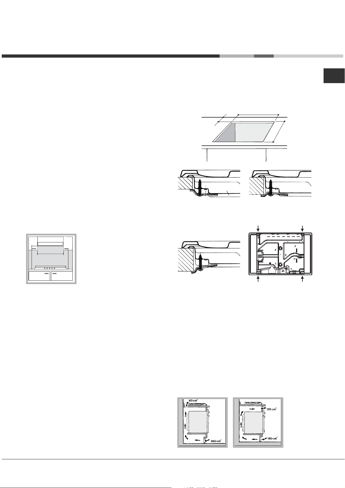
• The installation cavity should have the dimensions
indicated in the figure. Fastening hooks are provided,
allowing you to fasten the hob to tops that are between
20 and 40 mm thick. To ensure the hob is securely
fastened to the top, we recommend you use all the
hooks provided.
555 mm
55 mm
475 mm
Hook fastening diagram
Hooking position Hooking position
for top H=20 mm for top H=30 mm
Front
Hooking position Back
for top H=40 mm
! Use the hooks contained in the “accessory pack”
• Where the hob is not installed over a built-in oven, a
wooden panel must be installed as insulation. This
must be placed at a minimum distance of 20 mm from
the lower part of the hob.
Ventilation
To ensure adequate ventilation, the back panel of the
cabinet must be removed. It is advisable to install the
oven so that it rests on two strips of wood, or on a
completely flat surface with an opening of at least 45 x
560 mm (
see diagrams
).
AUS
3
Page 4

AUS
Electrical connection
Hobs equipped with a three-pole power supply cable are
designed to operate with alternating current at the voltage
and frequency indicated on the data plate (this is located
on the lower part of the appliance). The earth wire in the
cable has a green and yellow cover. If the appliance is to
be installed above a built-in electric oven, the electrical
connection of the hob and the oven must be carried out
separately, both for electrical safety purposes and to
make extracting the oven easier.
Connecting the supply cable to the mains
Install a standardised plug corresponding to the load
indicated on the data plate.
The appliance must be directly connected to the mains
using an omnipolar circuit-breaker with a minimum contact
opening of 3 mm installed between the appliance and the
mains. The circuit-breaker must be suitable for the charge
indicated and must comply with current electrical
regulations (the earthing wire must not be interrupted by the
circuit-breaker). The supply cable must not come into
contact with surfaces with temperatures higher than 50°C.
! The installer must ensure that the correct electrical
connection has been made and that it is compliant with
safety regulations.
Before connecting to the power supply, make sure that:
• The appliance is earthed and the plug is compliant with
the law.
• The socket can withstand the maximum power of the
appliance, which is indicated on the data plate.
• The voltage is in the range between the values
indicated on the data plate.
• The socket is compatible with the plug of the
appliance. If the socket is incompatible with the plug,
ask an authorised technician to replace it. Do not use
extension cords or multiple sockets.
! Once the appliance has been installed, the power supply
cable and the electrical socket must be easily accessible.
! The cable must not be bent or compressed.
! The cable must be checked regularly and replaced by
authorised technicians only (
! The manufacturer declines any liability should these
safety measures not be observed.
see Assistance
).
Gas connection
Check The Gas Type
! Before installation, check that the gas type (natural
gas or Universal LPG) of the cooker is suitable for
the gas type available to the installation. It is
extremely dangerous to use the wrong gas type with
any appliance, as fire or serious injury can result.
This cooker is supplied from the factory already set
for Natural Gas. To convert the cooker to LPG (or
back to Natural Gas from LPG), follow the directions
later in this section.
Fit regulator supplied for Natural Gas (if applicable)
at rear of appliance, and as close as practicable to
the appliance.
It is recommended that an isolating valve and union
be fitted, to enable simple disconnection for
servicing. These are to be in an accessible location.
! Check that the pressure of the gas supply is consistent
with the values indicated in Table 1 (“Burner and nozzle
specifications”). This will ensure the safe operation and
longevity of your appliance while maintaining efficient
energy consumption.
Pipe or Hose Connection
This appliance is suitable for use with either a
flexible connection or rigid copper connection.
Either a rigid metal pipe with fittings in compliance
with the standards in force must be used for
connecting to the nipple union (threaded ½”G male
fitting) situated at the rear of the appliance to the
right (fig.8), or an approved flexible hose of class B
or D.
Should it be necessary to turn the fitting, the gasket
(supplied with the appliance) must be replaced.
If a flexible hose is used, it should be as short as
possible with a maximum length of 1.2 metres;
• The flexible connection must be approved to
class B or D of AS/NZS1869 as a minimum.
• it should not be bent, kinked or compressed;
• it should not be in contact with the rear wall of the
appliance or in any case with parts which may
reach a temperature of 50°C;
• it should not come into contact with pointed parts
or sharp corners;
• it should not be subject to any pulling or twisting
forces;
• it should be easy to inspect along its entire length
in order to be able to check its condition.
• The supply connection point must be accessible
with the appliance installed.
• The inner diameters of the pipe are as follows:
8 mm for LPG;
13 mm for Natural Gas.
Checking the tightness of the connection
Upon completion of installation, check the gas
circuit, the internal connections and the taps for
leaks using a soapy solution (never a flame). Also
check that the connecting pipe cannot come into
contact with moving parts which could damage or
crush it. Make sure that the natural gas pipe is
4
Page 5
adequate for a sufficient supply to the appliance
when all the burners are lit
Duplicate Data Plate
Where the data plate is obscured by cabinetry when
the cooker is in the installed position, place a
duplicate data plate on a surface of the cabinetry
adjacent to the cooker.
AUS
Adapting to different types of gas
To adapt the hob to a different type of gas other than
default type (indicated on the rating plate at the base of
the hob or on the packaging), the burner nozzles should
be replaced as follows:
1. Remove the hob grids and slide the burners off their
seats.
2. Unscrew the nozzles using a 7 mm socket spanner,
and replace them with nozzles for the new type of gas
(see table 1 “Burner and nozzle characteristics”).
3. Reassemble the parts following the above procedure in
the reverse order.
4. Once this procedure is finished, replace the old rating
sticker with one indicating the new type of gas used.
Sticker are available from any of our Service Centres.
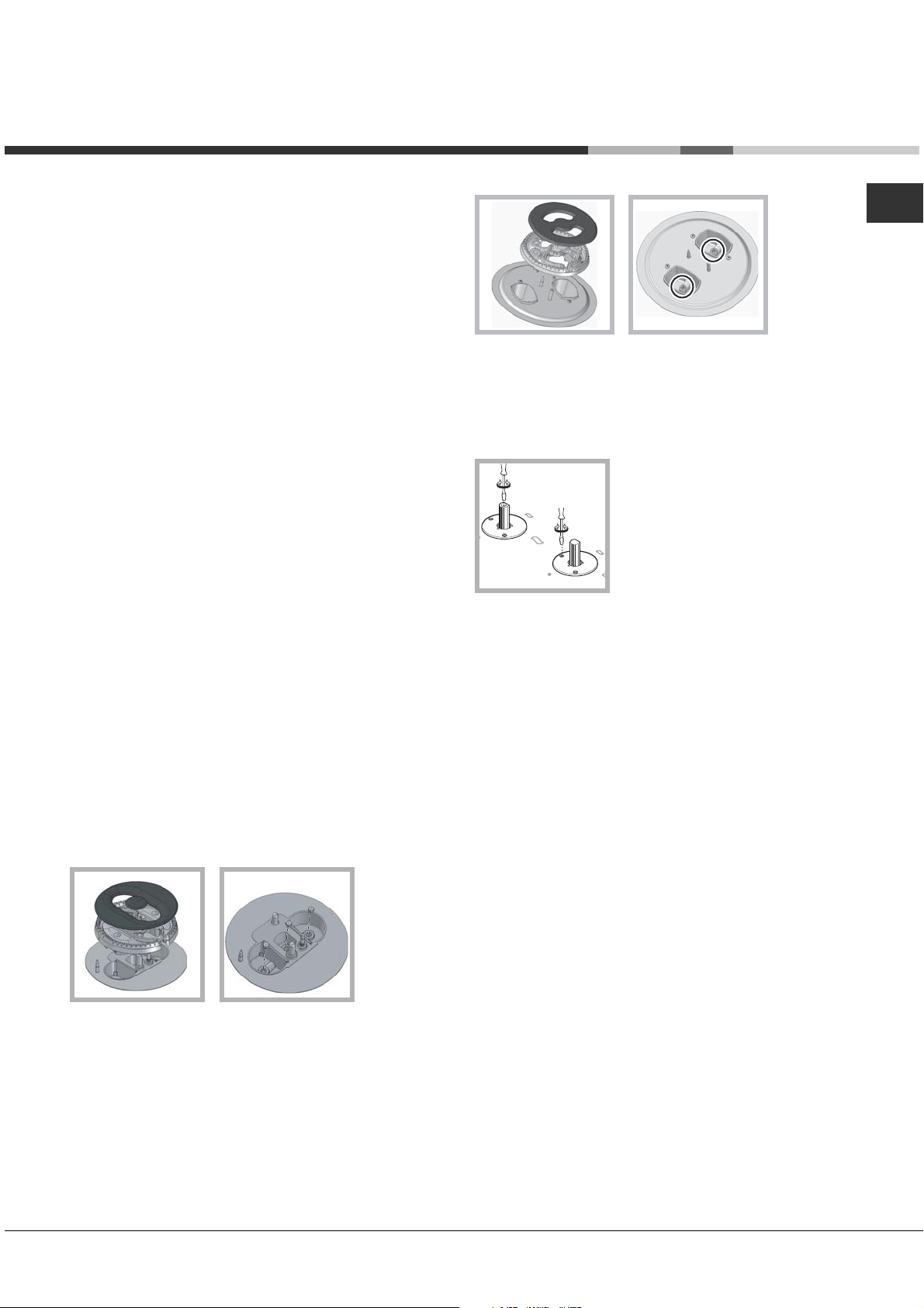
Replacing the nozzles on separate “double flame “
burners:
1. remove the grids and slide the burners from their
housings. The burner consists of 2 separate parts (
);
figure
2. unscrew the burers with a 7 mm wrench spanner. The
internal burner has a nozzle, the external burner has
two (of the same size). Replace the nozzle with models
suited to the new type of gas (see table 1).
3. replace all the components by repeating the steps in
reverse order.
see
• Adjusting the burners’ primary air :
Does not require adjusting.
• Setting the burners to minimum:
1. Turn the tap to the low flame position.
2. Remove the knob and adjust
the adjustment screw, which is
positioned in or next to the tap
pin, until the flame is small but
steady.
3. Having adjusted the flame to the required low setting,
while the burner is alight, quickly change the position of
the knob from minimum to maximum and vice versa
several times, checking that the flame does not go out.
4. Some appliances have a safety device (thermocouple)
fitted. If the device fails to work when the burners are
set to the low flame setting, increase this low flame
setting using the adjusting screw.
5. Once the adjustment has been made, replace the seals
on the by-passes using sealing wax or a similar
substance.
! If the appliance is connected to liquid gas, the regulation
screw must be fastened as tightly as possible.
! Once this procedure is finished, replace the old rating
sticker with one indicating the new type of gas used.
Stickers are available from any of our Service Centres.
! Should the gas pressure used be different (or vary
slightly) from the recommended pressure, a suitable
pressure regulator must be fitted to the inlet pipe (in order
to comply with current national regulations).
Replacing the Triple ring burner nozzles
1. Remove the pan supports and lift the burners out of
their housing. The burner consists of two separate parts
(see pictures).
2. Unscrew the nozzles using a 7 mm socket spanner.
Replace the nozzles with models that are configured
for use with the new type of gas (see Table 1). The two
nozzles have the same hole diameter.
3. Replace all the components by completing the above
operations in reverse order.
Post Installation Checks
Perform post installation checks and ensure proper
and safe operation before leaving. Test all burners
individually and in combination.
Leak Check
• Ensure all gas control knobs are in the Off
position.
• Ensure the gas supply is switched on.
5
Page 6

AUS
• Spray a solution of soapy water onto all gas joints
as well as the full length of any flexible hoses.
UNDER NO CIRCUMSTANCES USE A NAKED
FLAME IN CHECKING FOR LEAKS.
If bubbles appear anywhere, turn the gas supply off,
check all connections and retest. If satisfactory
operation cannot be achieved, contact place of
purchase or their appointed agent for service.
Flame check
Turn each burner on, and ensure that the flame is
blue with minimal yellow tipping. If there is
significant yellow tipping, flame lift off or excessive
noise, check pressure and adjust at the regulator if
necessary.
If satisfactory operation cannot be achieved, contact
place of purchase or their appointed agent for
service.
Igniter operation
Check that the igniter for each burner successfully
ignites the gas.
If an igniter fails to work, first remove the plug from
the electrical power outlet, and then check that all
the electrical connections are in place.
If satisfactory operation cannot be achieved, contact
place of purchase or their appointed agent for
service.
Low flame setting
Check the low flame setting for each hob burner to
ensure that the minimum flame will not be
extinguished by air draughts.
• Light the burner.
• Turn the control until it engages in the minimum
position.
• Ensure the flame is stable and will not be
extinguished by air draughts.
To adjust the minimum flame:
Follow the procedure described in the gas
conversion instruction.
DO NOT MODIFY THIS APPLIANCE IN ANY WAY,
OTHER THAN AS DESCRIBED IN THESE
INSTRUCTIONS.
6
Page 7
Gas Consumption
Natural Gas (1.0 kPa)
ULPG (2.75 kPa)
AUS
Ø Injector (mm)
Auxiliary Burner
Semi Rapid Burners
Wok Burner
Dual Control Wok Burner
Total
Gas Connection
Gas Inlet fitting 1/2” BSP (male) thread
Location of gas inlet 40 mm from rear edge
40 mm fro
0.85
1.10
1.19 (x2)
0.80 + 1.19 + 1.19
S
DC TC
A
GC (MJ/hr)
3.6
6.0
13.5
17.0
40.1
Ø Injector (mm)
0.50
0.64
0.70 (x2)
0.50 + 0.70 + 0.70
GC (MJ/hr)
3.3
5.5
13.0
16.5
38.3
PK 750 RT GH AUS
! The product was tested in accordance with AS4551 standard
7
Page 8
AUS
Gas Consumption
Natural Gas (1.0 kPa)
ULPG (2.75 kPa)
Ø Injector (mm)
Auxiliary Burner
Semi Rapid Burners
Rapid
Dual Control Wok Burner
Total
Gas Connection
Gas Inlet fitting 1/2” BSP (male) thread
Location of gas inlet 40 mm from rear edge
40 mm fro
0.85
1.10
1.24
0.85 + 1.07 + 1.07
A
R
DC
S
GC (MJ/hr)
3.6
6.0
7.8
13.0
30.4
Ø Injector (mm)
0.50
0.64
0.80
0.50 + 0.64 + 0.64
GC (MJ/hr)
3.3
5.5
9.0
13.0
30.8
PK 640 R GH AUS
! The product was tested in accordance with AS4551 standard
8
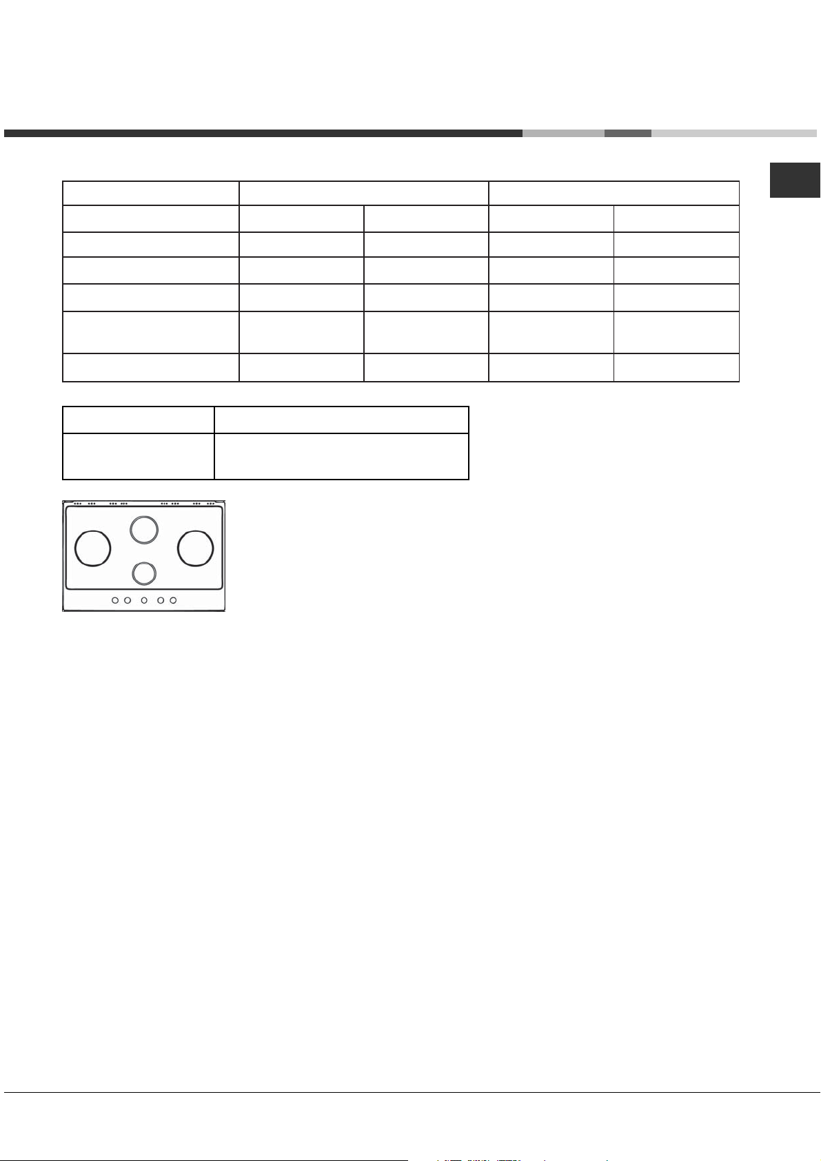
Page 9
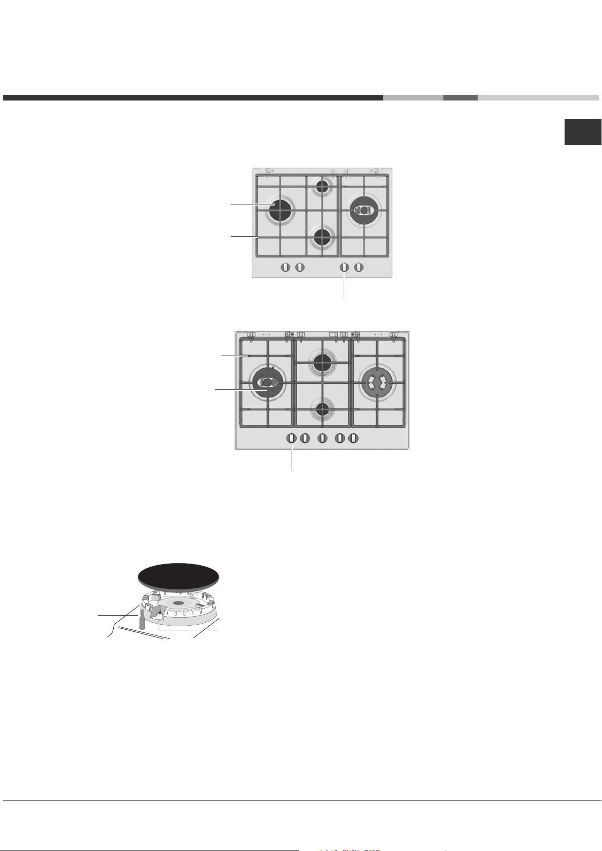
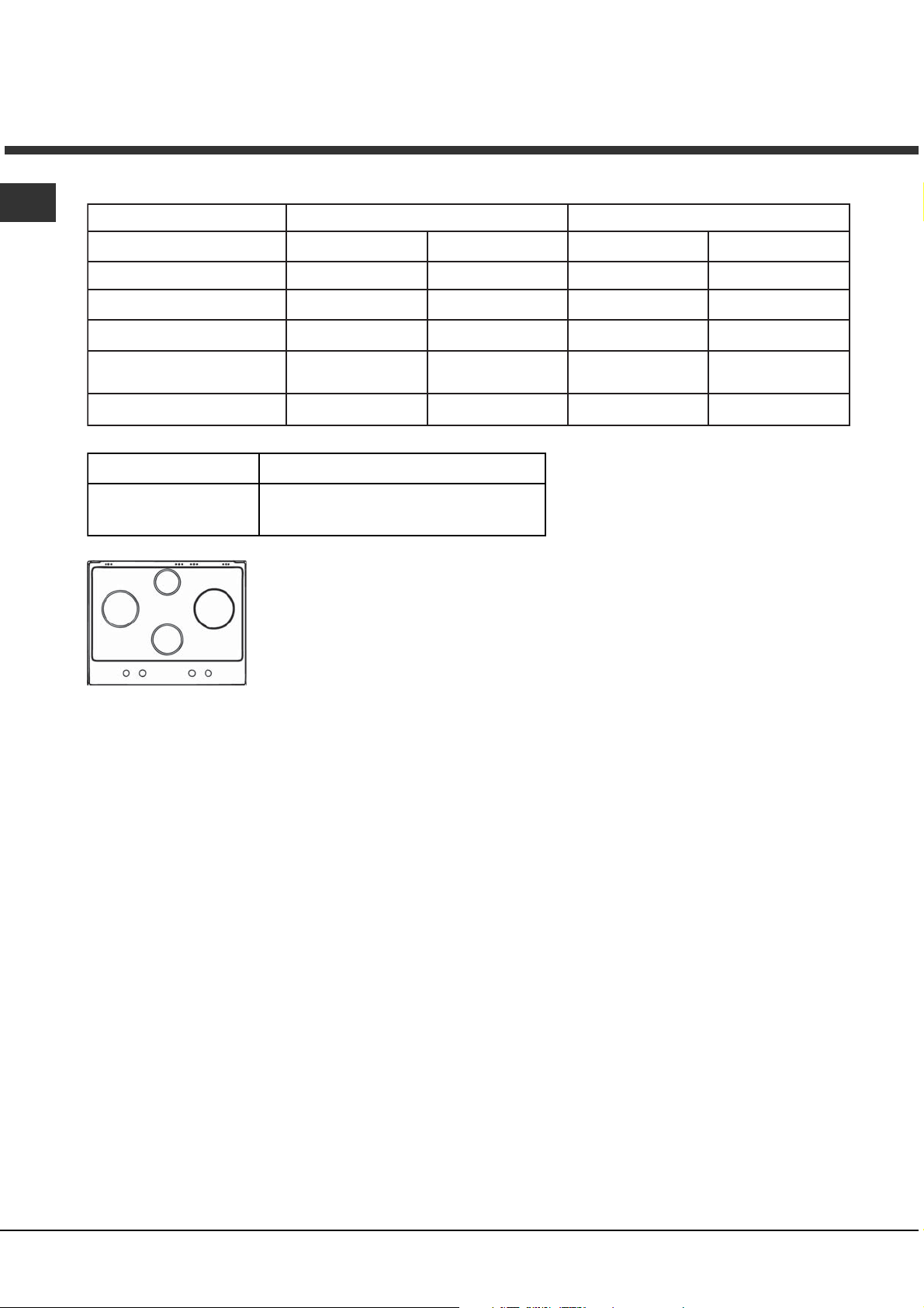
Description of the
appliance
Overall view
AUS
GAS BURNERS
Support Grid for
COOKWARE
Control Knobs for
GAS BURNERS
Support Grid for
COOKWARE
GAS BURNERS
Control Knobs for
GAS BURNERS
SAFETY
DEVICES *
• GAS BURNERS differ in size and power. Use the
diameter of the cookware to choose the most
appropriate burner to cook with.
• Control Knobs for GAS BURNERS adjust the size
of the flame.
Ignition for
GAS BURNERS *
• GAS BURNER ignition* enables a specific burner
to be lit automatically.
• SAFETY DEVICE* stops the gas flow if the flame
is accidentally extinguished.
9
Page 10
Start-up and use
AUS
! The position of the corresponding gas burner or
electric hotplate* is shown on every knob.
Gas cooker hobs are equipped with discrete power
adjustment that allows for accurately adjusting the
flame to 5 different power levels. Thanks to this
system, gas hobs are also capable of guaranteeing
the same cooking results for each recipe, as the
optimal power level for the desired type of cooking
can be identified in an easier, more accurate way.
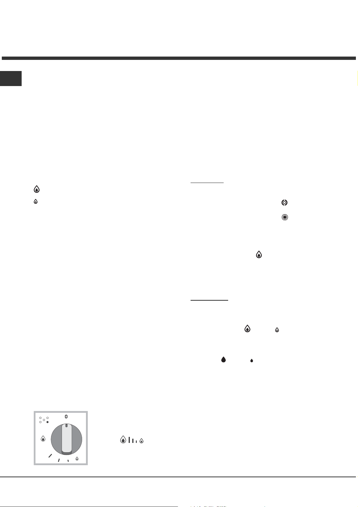
Gas burners
Each burner can be adjusted to one of the following
settings using the corresponding control knob:
• Off
Maximum
Minimum
To light one of the burners, hold a lit match or lighter
near the burner and, at the same time, press down
and turn the corresponding knob anti-clockwise to the
maximum setting.
Since the burner is fitted with a safety device, the
knob should be pressed for approximately 2-3
seconds to allow the automatic device keeping the
flame alight to heat up.
When using models with an ignition button, light the
desired burner pressing down the corresponding
knob as far as possible and turning it anticlockwise
towards the maximum setting.
! If a flame is accidentally extinguished, turn off the
control knob and wait for at least 1 minute before
trying to relight it.
To switch off the burner, turn the knob in a clockwise
direction until it stops (when reaches the “•” position).
Discrete flame adjustment
The selected burner can be adjusted - by means of
the knob - to 5 different power levels.
To shift between levels, simply turn the knob
towards the desired power level.
A click signals the passage from one power level to
the other.
The selected power level is
indicated by the
corresponding symbol
on (5 = max. power; 1 = min. power). The system
guarantees accurate flame adjustment and uniform
cooking results by facilitating selection of the
desired power level.
The "double-flame" burner
This gas burner consists of two concentric flame
rings that can operate jointly or independently (in
case of dual-control only).
As the burner is fitted with a safety device, the
knob should be pressed down for approximately 2-3
seconds until the device keeping the flame
automatically alight heats up.
Dual control:
Each ring comprising the burner has its own control
knob:
The knob marked with the symbol
outer ring.
The knob marked with the symbol
inner ring.
To activate any one of the two rings, press the
corresponding knob and turn it anti-clockwise to the
maximum power setting
In order to use the double-flame burner to its full
potential, avoid simultaneously setting the inner
ring to minimum power and the outer ring to
maximum power.
Single control:
The rings comprising the burner are activated
through a single control knob.
To simultaneously turn on both rings, position the
knob on the symbol
and turn the knob anti-clockwise.
To turn on the inner ring only, position the knob on
the symbol
the knob clockwise.
(to switch modes, it is necessary to switch off the
burner).
To switch off the burner, press and turn the knob
clockwise until it stops (when it reaches the "•"
position).
(max.) - (min.) then press and turn
.
(max.) - (min.) then press
controls the
controls the
10
(symbols
hobs equipped with a
display, by the LEDs that turn
) and, on
Page 11
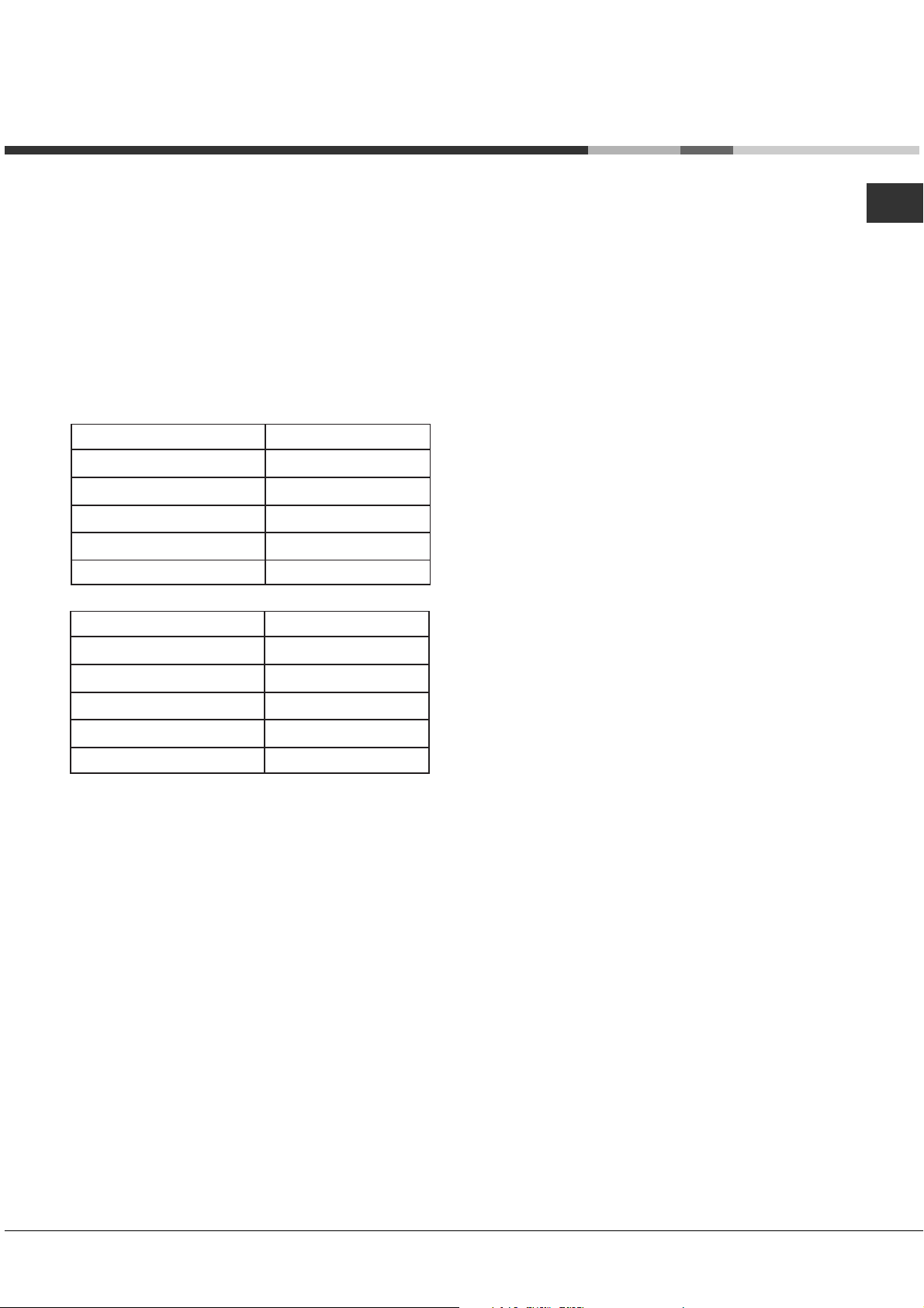
Practical advice on using the burners
To ensure the burners operate efficiently:
• Use appropriate cookware for each burner (see
table) so that the flames do not extend beyond
the bottom of the cookware.
• Always use cookware with a flat base and a cover.
• When the contents of the pan reach boiling point,
turn the knob to minimum.
AUS
Burner
Rapid (R)
Semi-Rapid (S)
Auxiliary (A)
Double Flame (DCDR internal)
Double Flame (DCDR external)
Ø Cookware Diameter (cm)
24 - 26
16 - 20
10 - 14
10 - 14
24 - 26
Pans to be used on 60 cm hobs
Burner
Semi-Rapid (S)
Auxiliary (A)
Triple Crown (TC)
Double Flame (DCDR internal)
Double Flame (DCDR external)
Ø Cookware Diameter (cm)
16 - 20
10 - 14
24 - 26
10 - 14
26 - 28
Pans to be used on 75 cm hobs
! On the models supplied with a reducer shelf,
remember that this should be used only for the
Double flame internal (DCDR internal) burner when
you use casserole dishes with a diameter under 12
cm.
To identify the type of burner, refer to the designs in
the section entitled, "Burner and Nozzle
Specifications".
11
Page 12

Precautions and tips
AUS
! This appliance has been designed and manufactured
in compliance with international safety standards. The
following warnings are provided for safety reasons and
must be read carefully.
General safety
• This is a class 3 built-in appliance.
• Gas appliances require regular air exchange to
maintain efficient operation. When installing the
hob, follow the instructions provided in the
paragraph on “Positioning” the appliance.
• These instructions are only valid for the countries
whose symbols appear in the manual and on the
serial number plate.
• The appliance was designed for domestic use inside
the home and is not intended for commercial or
industrial use.
• The appliance must not be installed outdoors, even in
covered areas. It is extremely dangerous to leave the
appliance exposed to rain and storms.
• Do not touch the appliance with bare feet or with wet
or damp hands and feet.
• The appliance must be used by adults only for the
preparation of food, in accordance with the
instructions outlined in this booklet. Any other
use of the appliance (e.g. for heating the room)
constitutes improper use and is dangerous. The
manufacturer may not be held liable for any
damage resulting from improper, incorrect and
unreasonable use of the appliance.
• Ensure that the power supply cables of other
electrical appliances do not come into contact with
the hot parts of the oven.
• The openings used for ventilation and dispersion of
heat must never be covered.
• Always make sure the knobs are in the “”/“
position when the appliance is not in use.
• When unplugging the appliance always pull the plug
from the mains socket, do not pull on the cable.
• Never carry out any cleaning or maintenance work
without having detached the plug from the mains.
• In case of malfunction, under no circumstances
should you attempt to repair the appliance yourself.
Repairs carried out by inexperienced persons may
cause injury or further malfunctioning of the
appliance. Contact a Service Centre (
Assistance
• Always make sure that pan handles are turned
towards the centre of the hob in order to avoid
accidental burns.
• Do not close the glass cover (if present) when the gas
burners are still hot.
).
see
”
• Do not use unstable or deformed pans.
Remove any liquid from the lid beforeRemove any liquid from the lid before
•
Remove any liquid from the lid before
Remove any liquid from the lid beforeRemove any liquid from the lid before
opening it.opening it.
opening it.
opening it.opening it.
• The appliance should not be operated by people
(including children) with reduced physical, sensory or
mental capacities, by inexperienced individuals or by
anyone who is not familiar with the product. These
individuals should, at the very least, be supervised
by someone who assumes responsibility for their
safety or receive preliminary instructions relating to
the operation of the appliance.
• Do not let children play with the appliance.
• The appliance is not intended to be operated by
means of an external timer or separate remotecontrol system.
Safety WarningsSafety Warnings
Safety Warnings
Safety WarningsSafety Warnings
• Do not use or store flammable materials near this
appliance.
• Do not spray aerosols in the vicinity of this appliance
while it is in operation.
• Do not modify this appliance.
• Not suitable for operation with aftermarket lids or
covers fitted.
• Where this appliance is installed in marine craft or in
caravans,it shall not be used as a space heater.
Disposal
• When disposing of packaging material: observe local
legislation so that the packaging may be reused.
• The European Directive 2002/96/EC on Waste
Electrical and Electronic Equipment (WEEE), requires
that old household electrical appliances must not be
disposed of in the normal unsorted municipal waste
stream. Old appliances must be collected separately
in order to optimise the recovery and recycling of the
materials they contain and reduce the impact on
human health and the environment. The crossed out
“wheeled bin” symbol on the product reminds you of
your obligation, that when you dispose of the
appliance it must be separately collected.
Consumers may take their old appliance to public
waste collection areas, other communal collection
areas, or if national legislation allows return it to a
retailer when purchasing a similar new product.
All major household appliance manufacturers are
active in the creation of systems to manage the
collection and disposal of old appliances.
12
Page 13
Maintenance and care
Switching the appliance off
Disconnect your appliance from the electricity supply
before carrying out any work on it.
Cleaning the appliance
! Do not use abrasive or corrosive detergents such as
stain removers, anti-rust products, powder detergents
or sponges with abrasive surfaces: these may scratch
the surface beyond repair.
! Never use steam cleaners or pressure cleaners on
the appliance.
• It is usually enough to wash the hob with a damp
sponge and dry it with absorbent kitchen roll.
• The removable parts of the burners should be
washed frequently with warm water and soap and
any burnt-on substances removed.
• For hobs which ligth automatically, the terminal part
of the electronic instant lighting devices should be
cleaned frequently and the gas outlet holes should
be checked for blockages.
Gas tap maintenance
AUS
Over time, the taps may become jammed or difficult
to turn. If this happens, the tap must be replaced.
! This procedure must be performed by a qualified
technician authorised by the manufacturer.
• Stainless steel can be marked by hard water that
has been left on the surface for a long time, or by
aggressive detergents containing phosphorus.
After cleaning, rinse and dry any remaining drops
of water.
!!
!
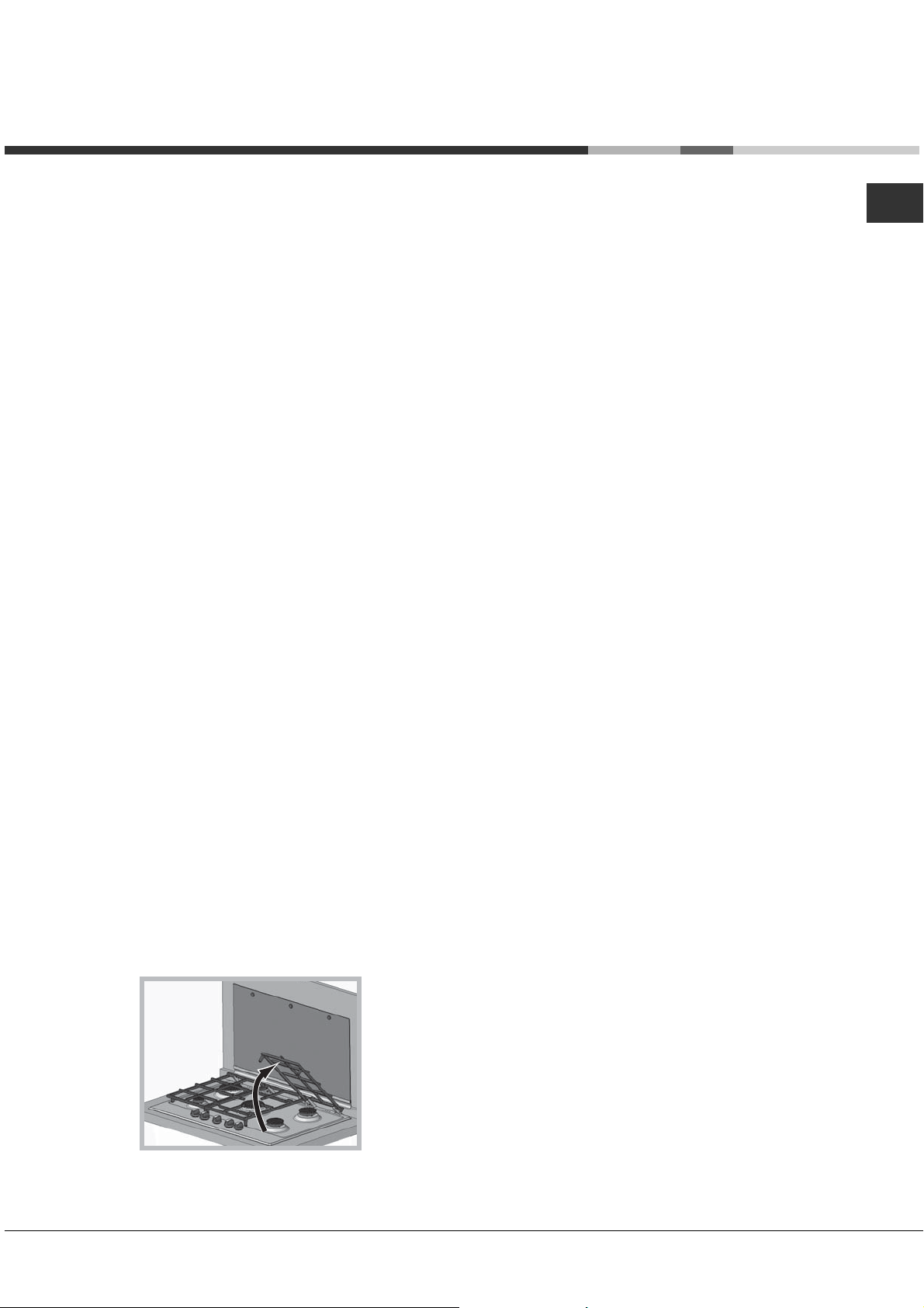
It is not necessary to remove the pan supports in
!!
order to clean the hob surface. Thanks to the
support system, simply lift and hold the pan
supports or rotate them until they rest against a rear
support.
Do not place the hot grids on top of the glass
cover (if applicable), otherwise the rubber plugs
on the glass may be damaged.
13
Page 14

Troubleshooting
AUS
It may happen that the appliance does not function properly or at all. Before calling the service centre for
assistance, check if anything can be done. First, check to see that there are no interruptions in the gas and
electrical supplies, and, in particular, that the gas valves for the mains are open.
Problem
The burner does not light or the flame is not
even around the burner.
The flame dies in models with a safety device.
The burner does not remain lit when set to
minimum.
The cookware is unstable.
Possible causes/Solution
• The gas holes on the burner are clogged.
• All the movable parts that make up the burner are
mounted correctly.
• There are draughts near the appliance.
• You pressed the knob all the way in.
• You keep the knob pressed in long enough to activate the
safety device.
• The gas holes are not blocked in the area corresponding
to the safety device.
• The gas holes are not blocked.
• There are no draughts near the appliance.
• The minimum setting has been adjusted properly.
• The bottom of the cookware is perfectly flat.
• The cookware is positioned correctly at the centre of the
burner.
• The pan support grids have been positioned correctly.
If, despite all these checks, the hob does not function properly and the problem persists, call the nearest
Customer Service Centre. Please have the following information handy:
• The appliance model (Mod.).
• The serial number (S/N).
This information can be found on the data plate located on the appliance and/or on the packaging.
! Never use unauthorised technicians and never accept replacement parts which are not original.
Service
Annual servicing by an authorised person is recommended. If the appliance produses unusal odour,
yellow tipping flame, flame lifting off the burner or is not performing as per original installation, or for
service please contact:
ARISTON
PRIORITY SERVICE
If you are not completely satisfied with your appliance
or require service call:
Australia
Phone: 1300 815 589
New Zealand
Phone: (09) 306 1020
AUSTRALIA
ARISIT PTY LIMITED
40-44 Mark Anthony Drive, Dandenong South,
VIC 3175, Australia
Fax: Service & Sales (03) 9768 0838
accessories are available for your appliance call:
NEW ZEALAND
ARISIT PTY LIMITED
PO Box 68-140 Newton, Auckland
1145, New Zealand
Fax: (09) 302 0077
GENUINE ACCESSORIES
& SPARE PARTS
A wide range of genuine
Australia
Phone: 03 9768 0888
New Zealand
Phone: (09) 306 1020
Email: consumer.care@arisit.com
14
Email: sales@aristonappliances.co.nz
Page 15

Mode d’emploi
TABLE DE CUISSON
AUS ES
FR
Français, 15English,1
Español, 29
PK 750 RT GH AUS
PK 640 R GH AUS
Sommaire
FR
Installation, 16-22
Positionnement
Raccordement électrique
Raccordement gaz
Plaquette signalétique
Caractéristiques des brûleurs et des injecteurs
Description de l’appareil, 23
Vue d’ensemble
Mise en marche et utilisation, 24-25
Conseils pratiques pour l’utilisation des brûleurs
Précautions et conseils, 26
Sécurité générale
Mise au rebut
Nettoyage et entretien, 27
Mise hors tension
Nettoyage de l’appareil
Entretien robinets gaz
Anomalies et remèdes, 28
15
Page 16

Installation
FR
! Avant d'utiliser votre nouvel appareil, veuillez lire cette
notice avec la plus grande attention. Elle contient des
informations importantes destinées à assurer votre
sécurité lors de l'utilisation, l'installation et l'entretien de
l'appareil.
! Veuillez conserver cette notice afin de pouvoir la
consulter ultérieurement. En cas de cession de l'appareil à
un tiers, veuillez également lui transmettre cette notice.
Conformité aux normes en vigueur
Cette table de cuisson doit être installée
conformément aux règles définies par les autorités
locales de gaz et d'électricité et aux dernières
versions publiées des normes suivantes :
• AS/NZS 5601 Code relatif à l'installation
d'appareils à gaz
• Règles de câblage de la SAA
Positionnement
! Conservez les matériaux d'emballage hors de portée
des enfants. Ils peuvent représenter un danger
d'étouffement
! L'appareil doit être installé par un professionnel qualifié
conformément aux instructions fournies. Une installation
incorrecte peut être à l'origine de blessures pour les
personnes et les animaux ou de dommages matériels.
Ventilation de la cuisine
Si la consommation totale de tous les appareils
dépasse les 3 MJ/h par mètre cube de la pièce ou
du volume de l'enceinte, l'espace doit être ventilé
par l'une des méthodes décrites en détails cidessous. Le critère " volume de la pièce " pris en
compte pour déterminer si la ventilation est
adéquate ou non correspond à l'espace ne pouvant
pas être isolé par des portes.
Ventilation naturelle directe venant de l'extérieur
Deux ouvertures permanentes vers l'extérieur
doivent être ménagées. Les ouvertures doivent être
placées de manière à assurer que la distance entre
le haut de l'ouverture supérieur et le plafond de la
pièce ou de l'enceinte, et la distance entre le bas de
l'ouverture inférieure et le sol de la pièce ou de
l'enceinte ne dépassent pas 5 % de la hauteur de la
pièce ou de l'enceinte. La surface de ventilation libre
minimale fournie par chaque ouverture sera calculée
en utilisant la formule suivante :
A = 3 × T
où
A = la surface de ventilation libre minimale (cm2)
T = la consommation totale de gaz de tous les
appareils (MJ/h)
La dimension verticale minimale de toute ouverture
de ventilation libre doit être de 6 mm.
NOTE 1
directement vers l'extérieur " signifie l'une des
options ci-dessous, à condition que le chemin de
ventilation ne soit pas obstrué par des matériaux de
construction ou d'isolation :
(a) Directement à travers un mur extérieur (option
préférée).
(voir Précautions et conseils)
Lorsqu'elle est utilisée ici, l'expression "
.
(b) À travers un mur extérieur mais avec un
décalage.
(c) Dans une cavité ventilée vers l'extérieur.
(d) Dans un espace situé sous le sol et ventilé
vers l'extérieur.
(e) Dans un espace en toiture ventilé vers
l'extérieur.
NOTE 2
combinées à condition que le haut et le bas de
l'ouverture atteignent les limites fixées dans cette
notice.
Ventilation naturelle par le biais d'une pièce
adjacente
Deux ouvertures permanentes doivent être
ménagées dans la pièce ou l'enceinte. Les
ouvertures doivent être placées de manière à
assurer que la distance entre le haut de l'ouverture
supérieur et le plafond de la pièce ou de l'enceinte,
et la distance entre le bas de l'ouverture inférieure et
le sol de la pièce ou de l'enceinte ne dépassent pas
5 % de la hauteur de la pièce ou de l'enceinte.
La surface de ventilation libre minimale fournie par
chaque ouverture sera calculée en utilisant la
formule suivante :
où
Ces exigences s'appliquent à toutes les pièces
suivantes, jusqu'à ce qu'une pièce soit ventilée vers
l'extérieur, conformément à la section précédente,
ou si la consommation totale de tous les appareils
ne dépasse pas les 3 MJ/h par mètre cube du
volume total de l'enceinte ou des pièces.
La dimension verticale minimale de toute ouverture
de ventilation libre doit être de 6 mm.
REMARQUE
combinées à condition que le haut et le bas de
l'ouverture atteignent les limites fixées dans cette
notice.
• Les gaz de pétrole liquéfiés, plus lourds que l'air, se
Les deux ouvertures peuvent être
A = 6 × T
A = la surface de ventilation libre minimale (cm2)
T = la consommation totale de gaz de tous les
appareils (MJ/h)
: :
: Les deux ouvertures peuvent être
: :
déposent et stagnent au niveau du sol. Par
conséquent, les pièces contenant des bouteilles de
gaz liquéfié doivent aussi disposer d'ouvertures vers
l'extérieur afin de permettre l'évacuation des
éventuelles fuites de gaz. C'est pourquoi les bouteilles
de gaz liquéfié, qu'elles soient partiellement ou
complètement pleines, ne doivent pas être installées
dans des pièces ou des espaces de stockage se
situant en-dessous du niveau du sol (par exemple,
dans des caves, etc.). Il est conseillée de ne conserver
dans la pièce que la bouteille en cours d'utilisation et
de la placer de telle sorte qu'elle ne puisse pas être
exposée à la chaleur produite par des sources
extérieures (fours, cheminées, poêles, etc.) qui
pourraient faire grimper la température de la bouteille
au-dessus de 50 °C.
16
Page 17

Mobilier adjacent
600mm min.
420mm min.
700mm min.
L'emplacement des points de raccordement est
indiqué au tableau situé à la page 5. Pour éviter les
problèmes de fonctionnement des appareils
encastrés dans des meubles, il convient de
respecter les distances minimales représentées sur
la figure 4. Il est recommandé que les surfaces
adjacentes de la cuisine soient capables de résister
à des températures de 65°C. Les conditions
suivantes doivent également être respectées :
• L'appareil doit être installé à proximité de mobilier
dont la hauteur ne dépasse pas le dessus de la
plaque de cuisson.
• Le mur en contact direct avec le panneau arrière
de la cuisinière doit être composé d'un matériau
non inflammable. Pendant le fonctionnement de
la cuisinière, le panneau arrière de cette dernière
peut atteindre une température de 50 °C
supérieure à la température de la pièce.
• Les meubles de cuisine installés à côté de la
cuisinière et qui sont plus hauts que le dessus de
la plaque de cuisson doivent être situés à au
moins 600 mm du bord de la plaque elle-même.
• Si la hotte est installée en-dessous d'un élément
mural, ce dernier doit être situé au moins 700 mm
(millimètres) au-dessus de la surface de la
plaque.
• Les meubles installés à côté de la hotte doit être
situé au moins 420 mm au-dessus de la plaque
de cuisson.
Il faut respecter les espacements minimum suivants
par rapport aux matériaux combustibles :
• L'espacement minimum
entre le bord du brûleur et le
mur latéral doit être de 200
mm.
• L'espacement minimum
entre le bord du brûleur et le
mur arrière doit être de 55
mm.
En cas d'installation au-dessus four encastré ne
disposant pas de ventilation forcée pour assurer son
refroidissement, il faut créer des ouvertures
d'aération afin de permettre une ventilation adéquate
à l'intérieur du meuble (au moins 200 cm² en bas
pour l'arrivée d'air et au moins 120 cm² en haut pour
la sortie).
Il faut en outre installer une planche de bois sous la
plaque de cuisson en guise d'isolation, à une
distance minimale de 15 mm du meuble
• Le trou réalisé pour y installer la plaque de cuisson doit
avoir les dimensions représentées sur la figure. Des
crochets de fixation sont fournis, destinés à fixer la
plaque de cuisson sur des plans de travail de 20 à 40
mm d'épaisseur. Pour assurer la bonne fixation de la
plaque sur le plan de travail, nous vous
recommandons d'utiliser tous les crochets fournis.
555 mm
55 mm
475 mm
Schéma de fixation des crochets
Position des crochets pour
un plan de travail de
20 mm20 mm
20 mm
20 mm20 mm
d'épaisseur
Position des crochets pour
un plan de travail de 30 mm
d'épaisseur
Avant
FR
Hottes
Les hottes et les systèmes de ventilation de plafond
doivent être installés selon les instructions du
fabricant mais l'espacement par rapport aux
brûleurs de la plaque de cuisson ne doit en aucun
cas être inférieur à 650 mm pour les hottes et 750
mm pour les systèmes de ventilation.
• Si la hotte est installée en-dessous d'un élément
mural, ce dernier doit être situé au moins 700 mm
(millimètres) au-dessus de la surface de la
plaque.
Installation de la table de cuisson au-dessus d'un
four
En cas d'installation de la table de cuisson audessus d'un four, il est impératif que ni le câble
d'alimentation électrique ni le tuyau de gaz (flexible
ou non) ne soient en contact avec les parties
chaudes du four.
Position des crochets pour
un plan de travail de 40 mm
d'épaisseur
Arrière
! Utilisez les crochets se trouvant dans le " kit
d'accessoires "
• Si la plaque de cuisson n'est pas installée au-dessus
d'un four encastré, il faut installer une planche de bois
en guise d'isolation. Celle-ci doit être placée à une
distance minimale de 20 mm de la partie inférieure de
la plaque de cuisson.
17
Page 18

FR
Ventilation
Pour assurer une ventilation adéquate, le panneau arrière
du meuble doit être retiré. Il est conseillé d'installer le four
de telle sorte qu'il repose sur deux tasseaux de bois ou
sur une surface complètement plante avec une ouverture
d'au moins 45 x 560 mm
(voir schémas)
.
Branchement électrique
Les plaques de cuisson équipées d'un câble
d'alimentation électrique à trois pôles sont conçues pour
fonctionner sur le courant alternatif à la tension et à la
fréquence indiquées sur la plaque signalétique (située
dans la partie inférieure de l'appareil). Le fil de terre dans
le câble possède une gaine de couleur verte et jaune. Si
l'appareil doit être installé au-dessus d'un four électrique
encastré, le raccordement électrique de la plaque de
cuisson et du four doit être réalisé séparément, à la fois
pour des raisons de sécurité électrique et pour faciliter
l'extraction du four.
Branchement du câble d'alimentation électrique au
réseau
Installez une fiche standard correspondant à la charge
indiquée sur la plaque signalétique.
L'appareil doit être raccordé directement au réseau
électrique en utilisant un disjoncteur omnipolaire ayant une
ouverture de contact minimum de 3 mm et installé entre
l'appareil et le réseau. Le disjoncteur doit être adapté à la
charge indiquée et doit être conforme aux réglementations
en vigueur en matière d'électricité (le fil de terre ne doit
pas être interrompu par le disjoncteur). Le câble
d'alimentation ne pas entrer en contact avec des surfaces
dont la température dépasse les 50°C.
! L'installateur doit s'assurer que le raccordement
électrique qui a été réalisé est correct et conforme aux
règles de sécurité en vigueur.
Avant le raccordement à l'alimentation électrique, assurezvous que :
• L'appareil est mis à la terre et la fiche est conforme aux
exigences légales.
• La prise de courant peut supporter la puissance
maximale de l'appareil qui est indiquée sur la plaque
signalétique.
• La tension est située dans la plage de valeurs indiquée
sur la plaque signalétique.
• La prise de courant est compatible avec la fiche de
l'appareil. Si la prise de courant n'est pas compatible
avec la fiche, demandez à un technicien agréé de la
remplacer. N'utilisez pas de rallonges ni de prises
multiples.
! Une fois l'appareil installé, le câble d'alimentation et la
prise de courant doivent être faciles d'accès.
! Le câble ne doit pas être plié ni comprimé.
! Le câble doit être inspecté régulièrement et remplacé
uniquement par des techniciens agréés (voir Assistance).
! Le fabricant décline toute responsabilité si ces mesures
de sécurité ne sont pas respectées.
Raccordement gaz
Vérifiez le type de gaz
! Avant l'installation, vérifiez que le type de gaz (gaz
naturel ou gaz liquéfié/propane) de la cuisinière est
adapté au gaz disponible dans le lieu d'installation.
Il est extrêmement dangereux d'utiliser le mauvais
type de gaz avec quelque appareil que ce soit. Cela
peut entraîner un incendie ou de blessures graves.
À sa sortie d'usine, cette cuisinière est configurée
pour fonctionner au gaz naturel. Pour utiliser la
cuisinière avec du gaz liquéfié (ou au gaz naturel
après l'avoir utilisée précédemment au gaz liquéfié),
veuillez suivre les indications reportées plus loin
dans cette section.
Installez le régulateur fourni pour le gaz naturel (le
cas échéant) à l'arrière de l'appareil et le plus près
possible de l'appareil.
Il est recommandé d'installer un robinet et un
raccord d'isolement afin de faciliter la déconnexion
pour les interventions d'entretien. Ces derniers
doivent être situés à un endroit accessible.
! Vérifiez que la pression de l'alimentation en gaz
correspond aux valeurs indiquées dans le Tableau 1 ("
Caractéristiques des brûleurs et des injecteurs "). Cela
garantira le fonctionnement en toute sécurité et la
longévité de votre appareil tout en conservant une bonne
efficacité énergétique.
Raccordement du tuyau ou flexible
Cet appareil est adapté pour être utilisé soit avec un
raccord flexible soit avec un raccord rigide en
cuivre.
Pour effectuer la connexion au raccord à mamelon
(raccord mâle G fileté de ½") situé à l'arrière de
l'appareil sur la droite (figure 8), il faut utiliser soit un
tuyau rigide en métal doté de raccords conformes
aux normes en vigueur soit un tuyau flexible de
classe B ou D.
Au cas où il serait nécessaire de tourner le raccord,
il faudra remplacer le joint d'étanchéité (fourni avec
l'appareil).
Si un tuyau flexible est utilisé, il devra être le plus
court possible, avec une longueur maximale de 1,5
mètres ;
• le raccord du flexible doit être conforme au
minimum à la classe B ou D de la réglementation
AS/NZS1869.
• il ne doit être ni plié, ni entortillé ni comprimé ;
• il ne doit pas être en contact avec la paroi arrière de
l'appareil ou, dans tous les cas, avec des pièces
pouvant atteindre une température de 50 °C ;
• il ne doit pas entrer en contact avec des éléments
18
Page 19

pointus ou des angles tranchants ;
• il ne doit pas être soumis à des forces de traction
ou de torsion ;
• il doit être facile à inspecter sur toute sa longueur
afin de pouvoir contrôler son état.
• Le point de connexion à l'alimentation doit être
accessible une fois l'appareil installé.
• Le diamètre intérieur du tuyau doit respecter les
conditions suivantes :
8 mm pour le gaz liquéfié ;
13 mm pour le gaz naturel.
Vérification de l'étanchéité du raccord
Une fois l'installation terminée, vérifiez le circuit de
gaz, les connexions internes et les robinets en
utilisant une solution savonneuse (jamais une
flamme). Vérifiez également que le tuyau de
raccordement ne peut pas entrer en contact avec
des parties mobiles qui pourraient l'endommager ou
l'écraser. Assurez-vous que le tuyau de gaz naturel
est adapté pour une alimentation en gaz suffisante
lorsque tous les brûleurs sont allumés.
Copie de la plaque signalétique
Si la plaque signalétique se trouve cachée par le
mobilier lorsque la cuisinière est en place, placez
une copie de la plaque signalétique sur une surface
du mobilier situé à côté de la cuisinière.
Adaptation aux différents types de gaz
Pour adapter l'appareil à un type de gaz autre que le gaz
par défaut (indiqué sur la plaque signalétique située à la
base de la plaque de cuisson ou sur l'emballage),
remplacez les injecteurs de tous les brûleurs en
procédant comme suit :
1. Enlevez les grilles du plan de cuisson et sortez les
brûleurs de leur logement.
2. Dévissez les injecteurs à l'aide d'une clé à douille de 7
mm et remplacez-les par les injecteurs adaptés au
nouveau type de gaz (voir tableau 1 " Caractéristiques
des brûleurs et des injecteurs ").
3. Remontez les différentes parties en effectuant la
procédure ci-dessus en sens inverse.
4. Une fois cette procédure terminée, remplacez
l'ancienne étiquette par une étiquette indiquant le
nouveau gaz utilisé. Vous pouvez vous procurer cette
étiquette auprès de n'importe lequel de nos Services
d'assistance.
Remplacement des injecteurs sur les brûleurs à "
deux flammes " indépendantes :
1. Retirez les grilles et faites glisser les brûleurs hors de
leurs logements. Le brûleur est composé de deux
parties distinctes
2. Dévissez les brûleurs à l'aide d'une clé plate de 7 mm.
Le brûleur interne possède un injecteur et le brûleur
externe en possède deux (de la même taille).
Remplacez l'injecteur par un modèle d'injecteur adapté
au nouveau type de gaz (voir tableau 1).
3. Remettez tous les composants en place en répétant
les étapes dans le sens inverse.
(voir figure)
;
FR
Remplacement des injecteurs du brûleur à triple
couronne
1. Retirez les supports pour casseroles et soulevez les
brûleurs hors de leur logement. Le brûleur est composé
de deux parties distinctes (voir figures).
2. Dévissez les injecteurs à l'aide d'une clé à douille de 7
mm. Remplacez les injecteurs par des modèles
d'injecteurs adaptés pour le nouveau type de gaz (voir
Tableau 1). Les deux injecteurs ont le même diamètre
d'orifice.
3. Remettez tous les composants en place en répétant
les opérations ci-dessus dans le sens inverse.
• Réglage de l'air primaire des brûleurs :
Ne nécessite pas de réglage.
• Réglage des brûleurs au minimum :
1. Tournez le robinet dans la position de minimum.
2. Retirez le bouton et ajustez la
vis de réglage qui se situe dans
ou à côté de la tige du robinet,
jusqu'à ce que la flamme soit
petite mais régulière.
3. Une fois obtenu le débit minimal souhaité, allumez le
brûleur et tournez brusquement le bouton de la position
de minimum à la position de maximum et vice versa à
plusieurs reprises, en vérifiant que la flamme ne s'éteint
pas.
4. Certains appareils sont équipés d'un système de
sécurité (thermocouple). Si l'appareil ne fonctionne pas
lorsque les brûleurs sont réglés sur la position de
minimum, augmentez le réglage du minimum à l'aide
de la vis de réglage.
5. Après avoir procédé à ce réglage, reposez les scellés
sur les by-pass en utilisant de la cire ou une substance
équivalente.
! Si l'appareil est raccordé à une bouteille de gaz liquide,
la vis de réglage doit être serrée au maximum.
19
Page 20

FR
! Une fois cette procédure terminée, remplacez l'ancienne
étiquette par une étiquette indiquant le nouveau gaz
utilisé. Vous pouvez vous procurer cette étiquette auprès
de n'importe lequel de nos Services d'assistance.
! Au cas où la pression de gaz utilisée serait différente (ou
seulement légèrement différente) de la pression
recommandée, il faut installer un régulateur de pression
adapté sur le tuyau d'arrivée de gaz (afin d'être en
conformité avec les réglementations nationales en
vigueur).
Vérifications après installation
Effectuez des vérifications après installation et
assurez-vous que l'appareil fonctionne correctement
et en toute sécurité avant de vous en éloigner.
Testez tous les brûleurs individuellement et l'un
après l'autre.
Vérification de la présente de fuite
• Veillez à ce que tous les boutons de commande
de gaz soient dans la position éteinte.
• Veillez à ce que l'alimentation en gaz soit ouverte.
• Vaporisez une solution d'eau savonneuse sur tous
les raccords de l'alimentation en gaz ainsi que sur
toute la longueur des tuyaux flexibles.
VOUS NE DEVEZ EN AUCUN CAS UTILISER UNE
FLAMME NUE AFIN DE DÉTECTER
L'ÉVENTUELLE PRÉSENCE DE FUITES DE GAZ.
Si des bulles apparaissent à un endroit ou un autre,
coupez l'alimentation en gaz, vérifiez tous les
raccords et refaites un test. Si vous ne parvenez
pas à un fonctionnement satisfaisant, contactez
votre lieu d'achat ou leur technicien d'entretien
agréé.
Réglage du minimum
Vérifiez le réglage du minimum pour chaque brûleur
de la plaque de cuisson afin de vous assurer que la
flamme minimale ne risque pas d'être éteinte par les
courants d'air.
• Allumez le brûleur.
• Tournez le bouton jusqu'à la position de minimum.
• Assurez-vous que la flamme est stable et ne
s'éteindra pas au moindre courant d'air.
Pour ajuster la flamme minimale :
Suivez la procédure décrite dans les instructions
relatives au changement de gaz utilisé.
NE MODIFIEZ EN AUCUN CAS CET APPAREIL SI
CE N'EST TEL QUE DÉCRIT DANS CETTE
NOTICE.
Vérification de la flamme
Allumez chaque brûleur et vérifiez que la flamme est
bleue avec le moins de jaune possible. S'il y a
beaucoup de jaune, si la flamme s'éteint ou bien si
la combustion est excessivement bruyante, vérifiez
la pression et ajustez-la au niveau du régulateur si
cela s'avère nécessaire.
Si vous ne parvenez pas à un fonctionnement
satisfaisant, contactez votre lieu d'achat ou leur
technicien d'entretien agréé.
Fonctionnement de l'allumeur
Vérifiez que l'allumeur de chaque brûleur parvient à
enflammer correctement le gaz.
Si un allumeur ne fonctionne pas, débranchez
d'abord la fiche de la prise de courant puis vérifiez
que toutes les connexions électriques sont
correctes.
Si vous ne parvenez pas à un fonctionnement
satisfaisant, contactez votre lieu d'achat ou leur
technicien d'entretien agréé.
20
Page 21

Consommation de gaz
Gaz naturel (1,0 kPa)
Gaz liquéfié (2,75 kPa)
FR
Diamètre des injecteurs
Brûleur auxiliaire
Brûleurs semi-rapides
Brûleur wok à
triple couronne
Double flamme
Total
Raccordement gaz
Raccord d'arrivée de gaz Filetage (mâle) BSP de 1/2”
Emplacement de
l'arrivée de gaz
0.85 mm
1,10 mm
2 x 1.19 mm
0.80 mm + 1.19 mm
+ 1.19 mm
40 mm du bord arrière
40 mm du bord latéral
Consommation de gaz
3.6 MJ/hr
6.0 MJ/h
13.5 MJ/hr
17.0 MJ/hr
40.1 MJ/hr
S
DC TC
A
Diamètre des injecteurs
0.50 mm
0,64 mm
2 x 0.70 mm
0.50 mm + 0.70 mm
+ 0.70 mm
Consommation de gaz
3.3 MJ/hr
5,5 MJ/h
13.0 MJ/hr
16.5 MJ/hr
38.3 MJ/hr
PK 750 RT GH AUS
! Le produit a été testé conforme à la norme AS4551
21
Page 22

FR
Consommation de gaz
Gaz naturel (1,0 kPa)
Gaz liquéfié (2,75 kPa)
Diamètre des injecteurs
Brûleur auxiliaire
Brûleurs semi-rapides
Rapide
Double flamme
Total
Raccordement gaz
Raccord d'arrivée de gaz Filetage (mâle) BSP de 1/2”
Emplacement de
l'arrivée de gaz
0.85 mm
1,10 mm
1.24 mm
0.85 mm + 1.07 mm
+ 1.07 mm
40 mm du bord arrière
40 mm du bord latéral
Consommation de gaz
3.6 MJ/hr
6.0 MJ/h
7.8 MJ/hr
13.0 MJ/hr
30.4 MJ/hr
A
R
DC
S
PK 640 R GH AUS
Diamètre des injecteurs
0.50 mm
0,64 mm
0.80 mm
0.50 mm + 0.64 mm
+ 0.64 mm
Consommation de gaz
3.3 MJ/hr
5,5 MJ/h
9.0 MJ/hr
13.0 MJ/hr
30.8 MJ/hr
! Le produit a été testé conforme à la norme AS4551
22
Page 23

Description
de l’appareil
Vue d’ensemble
Grilles support de
BRÛLEURS GAZ
FR
BRÛLEURS GAZ
Grilles support de
CASSEROLES
Manettes de commande des
BRÛLEURS GAZ
CASSEROLES
Manettes de commande des
BRÛLEURS GAZ
DISPOSITIF DE
SÉCURITÉ *
• BRÛLEURS GAZ ils ont plusieurs dimensions et
puissances. Choisissez celui qui correspond le
mieux au diamètre de votre casserole.
• Manettes de commande des BRÛLEURS GAZ
pour le réglage de la flamme.
Bougie d’allumage des
BRÛLEURS GAZ *
• La bougie d’allumage des BRÛLEURS GAZ*
permet l’allumage automatique du brûleur
sélectionné.
• DISPOSITIF DE SÉCURITÉ* en cas d’extinction
accidentelle de la flamme, coupez
immédiatement l’arrivée du gaz.
23
Page 24

Mise en marche et
utilisation
FR
! La position du brûleur gaz ou de la plaque électrique*
correspondante est indiquée sur chaque manette.
Les tables de cuisson sont équipées de réglage de
puissance " discret " permettant de régler avec
précision la flamme jusqu'à 5 niveaux différents.
Grâce à ce système, les tables à gaz permettent de
toujours obtenir les mêmes résultats pour chaque
recette car il est plus simple de repérer avec
précision le niveau de puissance optimal pour le
type de cuisson choisi.
Brûleurs à gaz
Chaque manette permet de régler le brûleur
sélectionné comme suit:
• Eteint
Maximum
Minimum
Pour allumer un brûleur, approchez une flamme ou
un allume-gaz, appuyez à fond et tournez la manette
correspondante dans le sens inverse des aiguilles
d’une montre pour sélectionner la position de
puissance maximale.
Sur les modèles équipés d’un dispositif de sécurité
gaz, appuyez pendant au moins 2-3 secondes de
suite sur la manette pour permettre au dispositif de
se réchauffer.
Pour allumer un brûleur sur les modèles équipés de
bougie d’allumage, appuyez ensuite à fond sur la
manette correspondante et tournez-la dans le sens
inverse des aiguilles d’une montre jusqu’à sa
position de puissance maximale.
! En cas d’extinction accidentelle des flammes du
brûleur, tournez la manette jusqu’à l’arrêt et attendez
au moins 1 minute avant de tenter de rallumer.
Pour éteindre le brûleur tournez la manette dans le
sens des aiguilles d’une montre pour la ramener en
face du symbole “•”.
Réglage " discret " de la flamme
Il est possible de régler à l'aide de la manette 5
niveaux de puissance pour le brûleur choisi.
Pour passer d'un niveau à
l'autre, il suffit de tourner la
manette vers le niveau choisi.
Un déclic /clic signale le
passage d'un niveau à
l'autre.
Le niveau sélectionné est
signalé par le symbole
correspondant (symboles ) et, sur les
tables équipées d'afficheur, par allumage des LED
(5 = puissance max. ; 1= puissance min.). Ce
système assure un réglage parfait de la flamme et
permet de toujours obtenir le même résultat de
cuisson car il est plus facile de régler le niveau de
puissance désiré.
Le brûleur à " deux flammes "
Ce brûleur à gaz est formé de deux anneaux de
flamme concentriques pouvant fonctionner ensemble
ou séparément (uniquement dans le cas de double
commande).
Le brûleur étant équipé d'un dispositif de sécurité
de flamme, appuyer pendant au moins 2-3
secondes de suite sur la manette pour permettre au
dispositif de se réchauffer.
Double commande :
Chaque couronne composant le brûleur a sa propre
manette de commande :
la manette caractérisée par le symbole
l'anneau extérieur ;
la manette caractérisée par le symbole
l'anneau intérieur ;
Pour allumer la couronne souhaitée, appuyer sur la
manette correspondante en tournant dans le sens
inverse des aiguilles d'une montre jusqu'à la
position de puissance maximale
Pour une utilisation optimale du foyer double
flamme, ne jamais régler, simultanément,
l'anneau du centre sur sa position minimale et
l'anneau extérieur sur sa position maximale.
Mono Commande :
Les couronnes qui composent le brûleur ont une
manette de commande.
Pour allumer les deux anneaux en même temps,
appuyer sur la manette en tournant dans le sens
inverse des aiguilles d'une montre jusqu'au symbole
(max) - (min).
Pour passer à l'allumage de l'anneau du centre
uniquement, appuyer sur la manette en tournant
dans le sens des aiguilles d'une montre jusqu'au
symbole
(pour passer d'un mode à l'autre, il faut éteindre le
brûleur).
Pour éteindre le brûleur, appuyer sur la manette en
tournant dans le sens des aiguilles d'une montre
pour la ramener en face du symbole “•”).
(max) - (min).
contrôle
contrôle
.
24
Page 25

Conseils pratiques pour l’utilisation des
brûleurs
Pour obtenir un meilleur rendement, n’oubliez pas :
• d’utiliser des récipients appropriés à chaque
brûleur (voir tableau) pour éviter que les flammes
ne dépassent de sous les casseroles.
• de toujours utiliser des casseroles à fond plat et
avec couvercle.
• de tourner la manette dans la position minimum
au moment de l’ébullition.
FR
Brûleurs
Rapide (R)
Semi Rapide (S)
Auxiliaire (A)
Deux Flammes (DCDR intérieur)
Deux Flammes (DCDR extérieur)
Casseroles à utiliser sur les tables de cuisson de 60 cm
Brûleurs
Semi Rapide (S)
Auxiliaire (A)
Triple Couronne (TC)
Deux Flammes (DCDR intérieur)
Deux Flammes (DCDR extérieur)
Casseroles à utiliser sur les tables de cuisson de 75 cm
Ø Récipients (cm)
24 - 26
16 - 20
10 - 14
10 - 14
24 - 26
Ø Récipients (cm)
16 - 20
10 - 14
24 - 26
10 - 14
26 - 28
! Sur les modèles munis de grille de réduction, cette
dernière ne doit être utilisée que sur le brûleur Deux
flammes intérieur (DCDR intérieur), lorsque l’on utilise
des récipients de diamètre inférieur à 12 cm.
Pour distinguer le type de brûleur reportez-vous aux
dessins figurant dans le paragraphe "Caractéristiques
des brûleurs et des injecteurs"
25
Page 26

Précautions et conseils
FR
! Cet appareil a été conçu et fabriqué conformément aux
normes internationales de sécurité. Ces conseils sont
fournis pour des raisons de sécurité et doivent être lus
attentivement.
Sécurité générale
• Ce mode d’emploi concerne un appareil à
encastrer classe 3.
• Pour bien fonctionner, les appareils à gaz ont
besoin d’un apport d’air régulier. Il est important
de vérifier lors de leur installation, que tous les
points indiqués dans le paragraphe relatif à leur
“Positionnement” soient respectés.
• Les instructions fournies ne sont applicables
qu’aux pays dont les symboles sont reportés dans
la notice et sur la plaquette d’immatriculation.
• Cet appareil a été conçu pour un usage familial, de
type non professionnel.
• Cet appareil ne doit pas être installé en extérieur, même
dans un endroit abrité, il est en effet très dangereux de
le laisser exposé à la pluie et aux orages.
• Ne touchez pas à l’appareil si vous êtes pieds nus ou si
vous avez les mains ou les pieds mouillés ou humides.
• Cet appareil qui sert à cuire des aliments ne doit
être utilisé que par des adultes conformément aux
instructions du mode d’emploi. Toute autre
utilisation (comme par exemple le chauffage d’une
pièce) est impropre et donc dangereux. Le fabricant
décline toute responsabilité en cas de dommages
provoqués par un usage impropre ou erroné.
• Evitez que le cordon d’alimentation d’autres petits
électroménagers touche à des parties chaudes du four.
• Les orifices ou les fentes d’aération ou d’évacuation de
la chaleur ne doivent pas être bouchés
• Contrôlez toujours que les manettes sont bien dans la
position “”/“
• Ne tirez surtout pas sur le câble pour débrancher la
fiche de la prise de courant.
• N’effectuez aucune opération de nettoyage ou
d’entretien sans avoir auparavant débranché la fiche
de la prise de courant.
• En cas de panne, n’essayez en aucun cas d’accéder
aux mécanismes internes pour tenter de réparer
l’appareil. Contactez le service d’Assistance (
Assistance
• Faites attention à ce que les manches des casseroles
soient toujours tournés vers l’intérieur de la table de
cuisson pour éviter tout risque d’accident.
• N’abaissez pas le couvercle en verre (s’il y en a un)
tant que les brûleurs gaz ou la plaque électrique sont
chauds.
• Ne laissez pas la plaque électrique allumée sans
casserole dessus.
” quand l’appareil n’est pas utilisé.
voir
).
• N’utilisez pas de casseroles instables ou déformées.
• Essuyez tout liquide pouvant se trouver sur le
couvercle avant de l'ouvrir.
• Cet appareil n’est pas prévu pour être utilisé par des
personnes (y compris les enfants) dont les capacités
physiques, sensorielles ou mentales sont réduites, ou
des personnes dénuées d’expérience ou de
connaissance, sauf si elles ont pu bénéficier, par
l’intermédiaire d’une personne responsable de leur
sécurité, d’une surveillance ou d’instructions
préalables concernant d’utilisation de l’appareil.
• S'assurer que les enfants ne jouent pas avec
l'appareil.
• Le dispositif n'est pas destiné à être mis en œuvre
par une minuterie externe ou un système de
télécommande séparée.
Mise au rebut
• Mise au rebut du matériel d’emballage : conformezvous aux réglementations locales, les emballages
pourront ainsi être recyclés.
• La Directive Européenne 2002/96/CEE sur les Déchets
des Equipements Electriques et Electroniques (DEEE),
exige que les appareils ménagers usagés ne soient
pas jetés dans le flux normal des déchets municipaux.
Les appareils usagés doivent être collectés
séparément afin d’optimiser le taux de récupération et
le recyclage des matériaux qui les composent et
réduire l’impact sur la santé humaine et
l’environnement. Le symbole de la ‘‘poubelle barrée’’
est apposée sur tous les produits pour rappeler les
obligations de collecte séparée.
Les consommateurs pourront confier leur appareil
usagé au service de collecte des collectivités locales
ou de leurs groupements, ou si la législation nationale
le permet, le rendre au revendeur lors de l’achat d’un
nouvel appareil similaire.
Tous les principaux fabricants d’appareils ménagers
travaillent activement dans la création et la gestion de
systèmes de collecte et d’enlèvement des appareils
usagés.
26
Page 27

Nettoyage et entretien
!!
!
Mise hors tension
Avant toute opération de nettoyage ou d’entretien
coupez l’alimentation électrique de l’appareil.
Nettoyage de l’appareil
! N’utilisez pas de détergents abrasifs ou corrosifs,
tels que détacheurs et dérouilleurs, poudres à récurer
et éponges à surface abrasive : ils risquent de rayer
irrémédiablement la surface.
! Ne nettoyez jamais l’appareil avec des nettoyeurs
vapeur ou haute pression.
• Pour un entretien courant, passez une éponge
humide sur la surface et séchez avec du papier
essuie-tout.
• Les parties démontables des brûleurs doivent être
lavées fréquemment à l’eau chaude avec du
détergent en éliminant soigneusement toute
incrustation.
• Dans le cas de tables équipées d’allumage
automatique, nettoyez fréquemment et
soigneusement l’extrémité des dispositifs
d’allumage électronique instantané et vérifiez que
les orifices de sortie du gaz ne sont pas bouchés.
Pas besoin de retirer les grilles pour nettoyer la
!!
surface du plan de cuisson. Grâce à leur système
de support, il suffit de soulever les grilles et de les
garder dans cette position ou des les faire pivoter
pour les poser sur un support arrière.
Attention à ne pas poser les grilles chaudes sur
l'éventuel couvercle en verre pour éviter que les
caoutchoucs sur le verre s'abîment.
Entretien robinets gaz
Il peut arriver qu’au bout d’un certain temps, un
robinet se bloque ou tourne difficilement. Il faut alors
le remplacer.
! Cette opération doit être effectuée par un
technicien agréé par le fabricant.
FR
• Des taches peuvent se former sur l’acier inox si
ce dernier reste trop longtemps au contact d’une
eau très calcaire ou de détergents agressifs
(contenant du phosphore). Il est conseillé de
rincer abondamment et d’essuyer après le
nettoyage. Mieux vaut essuyer aussitôt tout
débordement d’eau.
27
Page 28

FR
Anomalies et remèdes
Il peut arriver que l’appareil ne fonctionne pas ou ne fonctionne pas très bien. Avant d’appeler le service aprèsvente, voyons ensemble que faire. Vérifiez avant tout s’il n’y a pas de coupure de gaz ou de courant, et si les
robinets du gaz en amont de l’appareil sont bien ouverts.
Anomalies
Le brûleur ne s’allume pas ou la flamme n’est
pas uniforme.
La flamme s’éteint dans les versions
équipées de sécurité de flamme.
Le brûleur s’éteint quand il est réglé sur la
position de minimum.
Les casseroles sont instables.
Causes / Solutions possibles
• les orifices de sortie du gaz ne sont pas par hasard
bouchés.
• les pièces amovibles composant le brûleur sont bien
montées correctement.
• il y a des courants d’air dans les environs du plan de
cuisson
• vous avez bien appuyé à fond sur la manette.
• vous avez bien appuyé à fond sur la manette pendant un
laps de temps suffisant pour permettre l’activation du
dispositif de sécurité.
• les orifices de sortie du gaz situés en face du dispositif de
sécurité ne sont pas par hasard bouchés.
• les orifices de sortie du gaz ne sont pas par hasard
bouchés
• il y a des courants d’air dans les environs du plan de
cuisson
• les minima n’ont pas bien été réglés.
• le fond de la casserole est parfaitement plat
• la casserole est bien placée au centre du brûleur
• la position des grilles n’a pas par hasard été inversée.
Si, malgré tous ces contrôles, votre appareil ne fonctionne toujours pas et l’inconvénient persiste, faites appel à
notre station technique. Indiquez-lui :
• le modèle de votre appareil (Mod.)
• son numéro de série (S/N)
Ces informations figurent sur la plaquette signalétique apposée sur votre appareil et/ou sur son emballage.
! Ne faites jamais appel à des techniciens non agréés et refusez toujours l’installation de pièces détachées
non originales.
28
Page 29

Manual de
instrucciones
AUS
English,1
PK 750 RT GH AUS
PK 640 R GH AUS
FR
Français, 15
ES
Español, 29
ENCIMERA
Sumario
ES
Instalación, 30-36
Colocación
Conexión eléctrica
Conexión gas
Características de los quemadores e inyectores
Placa de características
Descripción del aparato, 37
Vista de conjunto
Puesta en funcionamiento y uso, 38-39
Consejos prácticos para el uso de los quemadores
Precauciones y consejos, 40
Seguridad general
Eliminación
Mantenimiento y cuidados, 41
Cortar la corriente eléctrica
Limpiar el aparato
Mantenimiento de las llaves de gas
Placa de características
Anomalías y soluciones, 42
29
Page 30

Instalación
ES
! Antes de desembalar el aparato, se ruega leer este
manual de instrucciones detenidamente. El manual
contiene información importante sobre la seguridad para
la instalación, el uso y el mantenimiento del aparato.
! Conserve estas instrucciones de uso para consultas
futuras. Entréguelas al futuro dueño en caso de cambio
de propiedad del aparato.
Conformidad con las normas
Esta placa de cocción se debe instalar según los
requisitos de las autoridades de gas y electricidad
locales y de conformidad con la versión más
reciente de las siguientes normas:
• Código de instalaciones de gas AS/NZS 5601
• Reglas de cableado SAA.
Emplazamiento
! Mantener el material de embalaje fuera del alcance de
los niños. El material de embalaje implica riesgos de
ahogo o sofocación
! El aparato debe ser instalado por un profesional
calificado según las instrucciones suministradas. Una
instalación incorrecta puede causar daños a personas,
animales y bienes.
Ventilación de la cocina
Si el consumo total de todos los aparatos es
superior a 3 MJ/h por cada metro cúbico del
ambiente o recinto, se deberá implementar uno de
los sistemas de ventilación enumerados a
continuación. Para evaluar si la ventilación es
adecuada, debe entenderse como "ambiente" el
volumen de la habitación no aislable mediante el
cierre de puertas.
Ventilación exterior natural directa
Debe haber dos aberturas permanentes directas al
exterior. La distancia entre el borde superior de la
abertura superior y el techo de la habitación o recinto
y la distancia entre el borde inferior de la abertura
inferior y el piso de la habitación o recinto no deben
ser superiores al 5% de la altura de la habitación o
recinto. El área mínima de ventilación de cada
abertura se calcula con la siguiente fórmula:
A = 3 × T
donde
A = área de ventilación mínima (cm2)
T = consumo de gas total de todos los aparatos
(MJ/h)
Cada abertura de ventilación debe medir como
mínimo 6 mm de alto.
NOTA 1
exterior" alude a cualquiera de las siguientes
opciones, siempre que el paso de la ventilación no
esté obstruido por material de construcción o
aislamiento:
En esta cláusula, el término "directo al
(ver Precauciones y consejos)
.
(a) Directamente a través de una pared externa
(opción preferida).
(b) A través de una pared externa pero
desfasada.
(c) A una cavidad ventilada hacia el exterior.
(d) A un espacio subterráneo ventilado hacia el
exterior.
(e) A un altillo ventilado hacia el exterior.
NOTA 2
que el borde superior e inferior de las aberturas
respeten los límites establecidos por esta cláusula.
Ventilación natural a través de una habitación
adyacente
Debe haber dos aberturas permanentes en la
habitación o recinto. La distancia entre el borde
superior de la abertura superior y el techo de la
habitación o recinto y la distancia entre el borde
inferior de la abertura inferior y el piso de la
habitación o recinto no deben ser superiores al 5%
de la altura de la habitación o recinto.
El área mínima de ventilación de cada abertura se
calcula con la siguiente fórmula:
donde
Estos requisitos se aplican a todas las habitaciones
subsiguientes hasta que haya una habitación con
ventilación al exterior, conforme a la sección
anterior, o que el consumo total de los aparatos no
sea superior a 3 MJ/h por cada metro cúbico del
volumen total de la habitación o recinto.
Cada abertura de ventilación debe medir como
mínimo 6 mm de alto.
NOTA
que el borde superior e inferior de las aberturas
respeten los límites establecidos por esta cláusula.
• El GLP tiende a bajar hacia el suelo, ya que es más
Armarios adyacentes
La ubicación de los puntos de conexión se indica en
la tabla de la página 5. Para utilizar los aparatos en
Es posible combinar dos aberturas siempre
A = 6 × T
A = área de ventilación mínima (cm2)
T = consumo de gas total de todos los aparatos
(MJ/h)
: :
: Es posible combinar dos aberturas siempre
: :
pesado que el aire. En consecuencia, las habitaciones
que contengan bombonas de GLP deberán estar
equipadas con ventiladores para que, en caso de
fugas, el gas se pueda evacuar. Por este motivo, no
hay que instalar o almacenar bombonas de GLP
parcial o totalmente llenas en habitaciones o áreas de
almacenaje subterráneas (sótanos, etc.). Se
recomienda conservar en la habitación sólo la
bombona en uso, en una posición no expuesta a calor
proveniente de fuentes externas (hornos, hogares,
calentadores, etc.)que podrían aumentar la temperatura
de la bombona a más de 50°C.
30
Page 31

la vivienda sin problemas, hay que respetar las
600mm min.
420mm min.
700mm min.
distancias mínimas indicadas en la figura 4. Las
superficies de la cocina adyacentes deberían poder
soportar una temperatura de 65°C. Además, se
deberán cumplir las siguientes condiciones:
• El aparato debería instalarse al lado de los
armarios, cuya altura no debería superar la altura
del borde superior de la placa de cocción.
• La pared en contacto directo con el panel posterior
de la placa de cocción debe ser de material no
inflamable. Durante el uso de la placa de cocción,
el panel posterior podría alcanzar una temperatura
50°C superior a la temperatura ambiente.
• Los armarios de cocina instalados al lado de la
placa de cocción que superen la altura de la
placa deberán estar al menos a 600 mm de
distancia del borde de la placa.
• Si la campana está instalada debajo de un
armario de pared, éste debe estar al menos 700
mm por encima de la superficie de la placa.
• Los armarios adyacentes a la campana deben
estar al menos 420 mm por encima de la placa.
Respetar las siguientes distancias mínimas a los
materiales combustibles:
• Distancia mínima del borde
del hornillo a la pared lateral:
200 mm.
• Distancia mínima del borde
del hornillo a la pared
posterior: 55 mm.
Campanas de extracción
Las campanas de extracción
y los ventiladores de escape
superiores se deben instalar siguiendo las
instrucciones del fabricante. De todas maneras,
deben quedar al menos 650 mm de distancia entre
los hornillos de la placa y la campana y al menos
750 mm de distancia entre los hornillos y los
ventiladores de escape superiores.
• Si la campana está instalada debajo de un
armario de pared, éste debe estar al menos 700
mm por encima de la superficie de la placa.
Instalación de la placa de cocción sobre un horno
Si la placa se instala sobre un horno, ni el cable
eléctrico ni el tubo o la manguera de gas deberían
entrar en contacto con partes calientes del
alojamiento del horno.
En caso de instalación sobre un horno empotrado
sin ventilación forzada, deberían proveerse
ventiladores adecuados (entrada de al menos 200
cm² en la base y salida de al menos 120 cm² en la
parte superior) para permitir una ventilación
adecuada dentro del alojamiento.
Debajo de la placa de cocción, al menos a 15 mm
del alojamiento de la placa, debería instalarse un
panel de madera aislante.
• El hueco de instalación debería ser de las medidas
indicadas en la figura. Se suministran ganchos de
fijación para fijar la placa a encimeras de 20 a 40 mm
de grosor. Para asegurarse de que la placa quede
firmemente fijada a la encimera se recomienda utilizar
todos los ganchos suministrados.
555 mm
55 mm
475 mm
Diagrama de fijación de los ganchos
Posición de fijación para
encimera de
H=20 mmH=20 mm
H=20 mm
H=20 mmH=20 mm
Posición de fijación para
encimera de
H=30 mmH=30 mm
H=30 mm
H=30 mmH=30 mm
Frente
Posición de fijación para
encimera de
H=40 mmH=40 mm
H=40 mm
H=40 mmH=40 mm
Lado posterior
! Utilizar los ganchos contenidos en el paquete de
accesorios.
• Si la placa no se instala sobre un horno empotrado, es
necesario instalar un panel de madera aislante.
Colocarlo al menos a 20 mm de la base de la placa.
Ventilación
Para garantizar una ventilación adecuada, es necesario
quitar el panel posterior del armario. Se recomienda
instalar el horno apoyado sobre dos bandas de madera o
sobre una superficie totalmente plana con una abertura de
al menos 45 x 560 mm
(ver diagramas)
.
ES
31
Page 32

ES
Conexión eléctrica
Las placas de cocción equipadas con cable de
alimentación eléctrica tripolares están diseñadas para
funcionar con corriente alterna a la tensión y frecuencia
indicadas en la placa de datos (situada en la parte inferior
del aparato). El conductor de tierra del cable es amarillo y
verde. Si el aparato se debe instalar sobre un horno
eléctrico empotrado, las conexiones eléctricas de la placa
y del horno se deben realizar por separado, tanto para
garantizar la seguridad eléctrica como para facilitar la
extracción del horno.
Conexión del cable de alimentación a la red eléctrica
Instalar una clavija estándar adecuada para la carga
indicada en la placa de datos.
El aparato se debe conectar directamente a la red
eléctrica utilizando un disyuntor omnipolar con una
apertura mínima de los contactos de 3 mm instalado entre
el aparato y la red. El disyuntor debe ser adecuado para
la carga indicada y debe cumplir con las normas
eléctricas vigentes (el cable de tierra no debe ser
interrumpido por el disyuntor). El cable de alimentación no
debe entrar en contacto con superficies que estén a más
de 50°C.
! El instalador debe garantizar una conexión eléctrica
correcta y conforme a las normas de seguridad.
Antes de la conexión a la alimentación eléctrica,
asegurarse de que:
• El aparato esté conectado a tierra y la clavija sea
conforme a la ley.
• La toma pueda soportar la potencia máxima del
aparato, indicada en la placa de datos.
• La tensión esté dentro de los valores indicados en la
placa de datos.
• La toma sea compatible con la clavija del aparato. Si la
toma es incompatible con la clavija, hacerla sustituir
por un técnico autorizado. No utilizar prolongadores ni
tomas múltiples.
! Una vez instalado el aparato, el cable de alimentación
eléctrica y la toma eléctrica deben quedar fácilmente
accesibles.
! El cable no se debe doblar ni comprimir.
! El cable se debe inspeccionar regularmente y, en caso
de necesidad de sustitución, debe ser sustituido por un
técnico autorizado
! El fabricante se exime de cualquier responsabilidad en
caso de incumplimiento de estas medidas de seguridad.
(ver Asistencia)
.
instalación. Es extremadamente peligroso utilizar un
tipo de gas no adecuado para el aparato: podrían
producirse incendios y lesiones graves.
Esta placa de cocción se suministra ajustada de
fábrica para gas natural. Para convertirla a GLP (o
de GLP a gas natural nuevamente) seguir las
instrucciones más adelante en esta sección.
Instalar el regulador suministrado para gas natural
(si corresponde) en la parte posterior del aparato, lo
más cerca posible del aparato.
Se recomienda instalar una válvula aislante y una
unión para facilitar la desconexión en caso de
reparaciones. Estos componentes deberían quedar
en una posición accesible.
! Comprobar que la presión del suministro de gas
corresponda a los valores indicados en la Tabla 1
("Especificaciones del hornillo y la boquilla"). Esto
garantizará el uso seguro y la longevidad del aparato
manteniendo eficiente el consumo de energía.
Conexión del tubo o la manguera
Este aparato es adecuado para el uso con
mangueras flexibles o con tubos rígidos.
Utilizar un tubo metálico rígido con empalmes
conformes a las normas vigentes o una manguera
flexible aprobada de clase B o D para la conexión al
niple (rosca ½"G macho) situado en la parte
posterior del aparato a la derecha (figura 8).
Si es necesario girar el empalme, sustituir la junta
(suministrada con el aparato).
Si se utiliza una manguera, ésta debería ser lo más
corta posible (longitud máxima 1,5 metros);
• La conexión flexible debe ser como mínimo de
clase B o D según la norma AS/NZS1869;
• No se debería plegar, enroscar ni comprimir;
• No debería entrar en contacto con la pared
posterior del aparato ni con partes que puedan
alcanzar una temperatura de 50°C;
• No debería entrar en contacto con partes
puntiagudas o aristas filosas;
• No debería estar sujeta a tirones o torceduras;
• Debería resultar fácil de inspeccionar en toda su
longitud.
• El punto de conexión de la alimentación debe
estar accesible con el aparato instalado.
• El diámetro interno del tubo debería ser de:
8 mm para GLP;
13 mm para gas natural.
Conexión del gas
Comprobación del tipo de gas
! Antes de la instalación, comprobar que el tipo de
gas (natural o GLP/propano) de la placa de cocción
coindica con el tipo de gas disponible en la
32
Comprobación del apriete de la conexión
Terminada la instalación, comprobar que no haya
fugas en el circuito del gas, en las conexiones
internas y en las llaves, utilizando una solución
jabonosa (nunca una llama). Comprobar también
Page 33

que el tubo de conexión no pueda entrar en contacto
con partes móviles que puedan dañarlo o aplastarlo.
Asegurarse de que el tubo de gas natural sea
adecuado para un suministro suficiente al aparato
cuando se enciendan los hornillos.
Duplicado de la placa de datos
Una vez instalada la placa de cocción, si la placa
de datos queda ocultada por los armarios, poner un
duplicado sobre una superficie del armario
adyacente a la placa de cocción.
Adaptación a otro tipo de gas
Para adaptar la placa de cocción a un tipo de gas
diferente del tipo que viene ajustado de fábrica (indicado
en la placa de datos en la base de la placa o en el
embalaje), es necesario sustituir las boquillas de los
hornillos de la siguiente manera:
1. Retirar las rejillas de la placa y desplazar los hornillos
de sus alojamientos.
2. Desenroscar las boquillas utilizando una llave de tubo
de 7 mm y sustituirlas con boquillas adecuadas para el
nuevo tipo de gas (ver la tabla 1 "Características del
hornillo y la boquilla").
3. Reensamblar las partes siguiendo la secuencia
contraria al procedimiento anterior.
4. Una vez terminado el procedimiento, sustituir la
etiqueta adhesiva anterior con una que indique el
nuevo tipo de gas. Hay etiquetas disponibles en
nuestros Centros de Asistencia.
hornillos de sus alojamientos. El hornillo consiste en
dos partes separadas (ver las figuras).
2. Desenroscar las boquillas con una llave de tubo de 7
mm. Sustituir las boquillas con modelos adecuados
para el nuevo tipo de gas (ver la tabla 1). El diámetro
del agujero de ambas boquillas es el mismo.
3. Sustituir todos los componentes siguiendo la secuencia
contraria al procedimiento anterior.
• Ajuste del aire primario de los hornillos:
No requiere ajustes.
• Ajuste de los hornillos al mínimo:
1. Girar la llave a la posición de llama baja.
2. Sacar el pomo y regular el
tornillo de ajuste, situado dentro o
al lado del perno de la llave,
hasta que la llama sea pequeña
pero constante.
ES
Sustitución de las boquillas en los hornillos de "doble
llama":
1. Retirar las rejillas de la placa y desplazar los hornillos
de sus alojamientos. El hornillo consiste en 2 partes
separadas
2. Desenroscar los hornillos con una llave de tubo de 7
mm. El hornillo interno tiene una boquilla; el externo
tiene dos (del mismo tamaño). Sustituir la boquilla con
un modelo adecuado para el nuevo tipo de gas (ver la
tabla 1).
3. Sustituir todos los componentes siguiendo la secuencia
contraria al procedimiento anterior.
Sustitución de las boquillas de los hornillos de triple
llama
1. Retirar los soportes para las ollas y levantar los
(ver la figura)
.
3. Una vez ajustada la llama baja, con el hornillo
encendido, cambiar rápidamente la posición del pomo
varias veces, del mínimo al máximo y viceversa,
asegurándose de que la llama no se apague.
4. Algunos aparatos tienen incorporado un dispositivo de
seguridad (termopar). Si el dispositivo no funciona
cuando los hornillos están regulados en la llama baja,
aumentar el ajuste de la llama baja utilizando el tornillo
de ajuste.
5. Una vez realizado el ajuste, sellar los by-pass con cera
selladora o un producto similar.
! Si el aparato está conectado a gas líquido, el tornillo de
ajuste se debe apretar al máximo.
! Una vez terminado el procedimiento, sustituir la etiqueta
adhesiva anterior con una que indique el nuevo tipo de
gas. Hay etiquetas disponibles en nuestros Centros de
Asistencia.
! Si la presión del gas es diferente (o varía ligeramente)
respecto de aquella recomendada, instalar un regulador
de presión adecuado en el tubo de entrada (conforme a
las normas nacionales vigentes).
33
Page 34

ES
Controles después de la instalación
Controlar la instalación y asegurarse de que el
funcionamiento sea correcto y seguro. Probar todos
los hornillos individual y conjuntamente.
Control de fugas
• Asegurarse de que todos los selectores del gas
estén en Off.
• Asegurarse de que el suministro de gas esté
activado.
• Pulverizar una solución de agua jabonosa sobre
todas las articulaciones y en toda la longitud de
las mangueras. NO UTILIZAR NUNCA LLAMAS
LIBRES PARA COMPROBAR LA AUSENCIA DE
FUGAS.
Si aparecen burbujas, desactivar el suministro de
gas, controlar todas las conexiones y volver a
probar. Si el resultado no es satisfactorio, contactar
con el vendedor y con el agente para pedir
asistencia.
Control de la llama
Encender cada uno de los hornillos y asegurarse de
que la llama sea azul con una leve punta amarilla. Si
la llama está muy amarilla, se levanta demasiado o
hace demasiado ruido, verificar la presión y ajustar
el regulador.
Si el resultado no es satisfactorio, contactar con el
vendedor y con el agente para pedir asistencia.
Encendido
Comprobar que el encendedor de cada hornillo
efectivamente encienda el gas.
Si un encendedor no funciona, desconectar la clavija
de la toma de alimentación eléctrica y comprobar
que todas las conexiones eléctricas sean correctas.
Si el resultado no es satisfactorio, contactar con el
vendedor y con el agente para pedir asistencia.
Ajuste de llama baja
Controlar el ajuste de la llama baja de cada hornillo
para asegurarse de que el fuego al mínimo no
pueda ser apagado por corrientes de aire.
• Encender el hornillo.
• Girar el mando hasta la posición mínima.
• Asegurarse de que la llama sea estable y no se
apague por corrientes de aire.
Para ajustar la llama al mínimo:
Seguir el procedimiento descrito en las instrucciones
de conversión a otro tipo de gas.
NO MODIFICAR ESTE APARATO DE UNA
MANERA QUE NO ESTÉ INDICADA EN ESTAS
INSTRUCCIONES.
34
Page 35

Consumo de gas
Gas natural (1.0 kPa)
GLP (2.75 kPa)
ES
Diámetro del inyector
Hornillo auxiliar
Hornillos semirrápidos
Hornillo wok de triple llama
Doble llama
0.85 mm
1.10 mm
2 x 1.19 mm
0.80 mm + 1.19 mm
+ 1.19 mm
Total
Conexión del gas
Empalme de entrada del gas Rosca 1/2” BSP (macho)
Ubicación de la
entrada de gas
40 mm desde el borde posterior
40 mm desde el borde lateral
S
DC TC
A
Entrada de gas
3.6 MJ/hr
6.0 MJ/h
13.5 MJ/hr
17.0 MJ/hr
40.1 MJ/hr
Diámetro del inyector
0.50 mm
0.64 mm
2 x 0.70 mm
0.50 mm + 0.70 mm
+ 0.70 mm
Entrada de gas
3.3 MJ/hr
5.5 MJ/h
13.0 MJ/hr
16.5 MJ/hr
38.3 MJ/hr
PK 750 RT GH AUS
! El producto ha sido probado según la norma AS4551
35
Page 36

ES
Consumo de gas
Gas natural (1.0 kPa)
GLP (2.75 kPa)
Diámetro del inyector
Hornillo auxiliar
Hornillos semirrápidos
Ràpido
Doble llama
0.85 mm
1.10 mm
1.24 mm
0.85 mm + 1.07 mm
3.6 MJ/hr
6.0 MJ/h
7.8 MJ/hr
13.0 MJ/hr
+ 1.07 mm
Total
30.4 MJ/hr
Conexión del gas
Empalme de entrada del gas Rosca 1/2” BSP (macho)
Ubicación de la
entrada de gas
40 mm desde el borde posterior
40 mm desde el borde lateral
A
R
DC
S
PK 640 R GH AUS
Entrada de gas
Diámetro del inyector
0.50 mm
0.64 mm
0.80 mm
0.50 mm + 0.64 mm
0.64 mm
Entrada de gas
3.3 MJ/hr
5.5 MJ/h
9.0 MJ/hr
13.0 MJ/hr
30.8 MJ/hr
! El producto ha sido probado según la norma AS4551
36
Page 37

Descripción
del aparato
Vista de conjunto
RECIPIENTES DE COCCIÓN
RECIPIENTES DE COCCIÓN
ES
QUEMADORES
Parrillas de apoyo de
Mandos de selección de los
QUEMADORES
Parrillas de apoyo de
QUEMADORES
Mandos de selección de los
QUEMADORES
DISPOSITIVO DE
SEGURIDAD *
• QUEMADORES A GAS: son de distintas
dimensiones y potencias. Elija siempre el más
adecuado para el diámetro del recipiente que va a
utilizar.
• Mandos de los QUEMADORES A GAS para la
regulación de la llama.
Bujía de encendido de los
QUEMADORES A GAS *
• Bujía de encendido de los QUEMADORES A
GAS:* permite el encendido automático del
quemador.
• DISPOSITIVO DE SEGURIDAD:* si se apaga
accidentalmente la llama, interrumpe la salida de
gas.
37
Page 38

Puesta en
funcionamiento y uso
ES
! En cada mando está indicada la posición del
quemador a gas o de la placa eléctrica*
correspondiente.
Las encimeras a gas poseen regulación discreta de
la potencia lo que permitirá regular con precisión la
llama en 5 niveles diferentes. Gracias a este
sistema será posible obtener siempre los mismos
resultados para cada receta, ya que será más
simple y precisa la individualización del nivel de
potencia óptimo para el tipo de cocción elegido,
incluso para las encimeras a gas.
Quemadores a gas
El quemador elegido se puede regular con el mando
correspondiente de la siguiente manera:
• Apagado
Máximo
Mínimo
Para encender uno de los quemadores, acerque al
mismo una llama o un encendedor, pulse a fondo y
gire el mando correspondiente en sentido antihorario
hasta la posición de máxima potencia.
En los modelos que poseen dispositivo de seguridad
es necesario mantener presionado el mando durante
2-3 segundos aproximadamente hasta que se caliente
el dispositivo que mantiene automáticamente
encendida la llama.
En los modelos que poseen bujía de encendido, para
encender el quemador elegido, pulse a fondo y gire el
mando correspondiente en sentido antihorario hasta
la posición de máxima potencia.
! Si se apagara accidentalmente la llama del
quemador, cierre el mando y vuelva a intentar
encenderlo después de 1 minuto, como mínimo.
Para apagar el quemador es necesario girar el mando
en sentido horario hasta el apagado (correspondiente
al símbolo “•”).
través del símbolo correspondiente (símbolos
a través del encendido de los LED (5 = máx.
potencia, 1 = mín. potencia). El sistema garantiza
una perfecta regulación de la llama y permite
obtener el mismo resultado de cocción,
individualizando más fácilmente el nivel de potencia
deseado.
El quemador de "dos llamas"
Este quemador a gas está formado por dos fuegos
concéntricos que pueden funcionar juntos o de
manera independiente (sólo en el caso del doble
mando).
Debido a que el quemador está dotado de un
dispositivo de seguridad, es necesario mantener
presionada la perilla durante 2 o 3 segundos hasta
que se caliente el dispositivo que mantiene la llama
encendida automáticamente.
Doble mando:
Cada corona que compone el quemador tiene su
mando:
el mando identificado con el símbolo
corona externa;
el mando identificado con el símbolo
corona interna.
Para encender la corona deseada, presione y gire el
mando correspondiente en sentido antihorario hasta
llegar a la posición de máxima potencia
Para utilizar en forma óptima el quemador de
llama doble, no regule nunca simultáneamente la
corona interna al mínimo y la externa al máximo.
Mono Mando:
Las coronas que componen el quemador poseen un
mando.
Para encender ambas coronas simultáneamente
presione y gire el mando en sentido antihorario
hasta el símbolo
) y, en las encimeras que poseen pantalla,
controla la
controla la
.
(máx) - (mín).
Regulación discreta de la llama
El quemador elegido se puede regular en 5 niveles
distintos de potencia, utilizando el mando
correspondiente.
Para pasar de un nivel a otro
basta girar el mando hacia el
nivel elegido.
Un disparo/clic advierte el
paso de un nivel a otro.
La visualización del nivel
seleccionado se produce a
38
Para pasar a la corona interna solamente presione y
gire el mando en sentido horario hasta el símbolo
(máx) - (mín).
(para pasar de una modalidad a otra, se debe
apagar el quemador).
Para apagar el quemador es necesario presionar y
girar el mando “•” en sentido horario hasta el tope.
Page 39

Consejos prácticos para el uso de los
quemadores
Si desea obtener el máximo rendimiento, es útil
recordar lo siguiente:
• utilice recipientes adecuados para cada
quemador (ver la tabla) con el fin de evitar que
las llamas sobresalgan por el fondo de los
recipientes.
• utilice siempre recipientes con el fondo plano y
con tapa.
• cuando se produce la ebullición, gire el mando
hasta la posición de mínimo.
ES
Quemador
Rápido (R)
Semi Rápido (S)
Auxiliar (A)
Doble llama (DCDR Interno)
Doble llama (DCDR Externo)
Ø Diámetro Recipientes (cm)
24 - 26
16 - 20
10 - 14
10 - 14
24 - 26
Ollas que deben utilizarse en placas de 60 cm
Quemador
Semi Rápido (S)
Auxiliar (A)
Corona Triple (TC)
Doble llama (DCDR Interno)
Doble llama (DCDR Externo)
Ø Diámetro Recipientes (cm)
16 - 20
16 - 20
24 - 26
10 - 14
26 - 28
Ollas que deben utilizarse en placas de 75 cm
! En los modelos dotados de rejilla de reducción,
esta última deberá ser usada únicamente para el
quemador Doble llama interno (DCDR Interno),
cuando se usan recipientes de diámetro inferior a 12
cm.
Para identificar el tipo de quemador ver los diseños
presentes en el párrafo "Características de los
quemadores y boquillas".
39
Page 40

Precauciones y consejos
ES
! El aparato ha sido proyectado y fabricado en
conformidad con las normas internacionales de
seguridad. Estas advertencias se suministran por
razones de seguridad y deben ser leídas atentamente.
Seguridad general
• Este aparato se refiere a un aparato empotrable de
clase 3.
• Para su correcto funcionamiento, los aparatos a
gas necesitan un regular cambio de aire. Verifique
que en su instalación se respeten los requisitos
contenidos en el párrafo correspondiente a la
“Colocación”.
• Las instrucciones son válidas sólo para los países
de destino, cuyos símbolos figuran en el manual y
en la placa de características.
• El aparato ha sido fabricado para un uso de tipo no
profesional en el interior de una vivienda.
• El aparato no se debe instalar al aire libre, tampoco si
el espacio está protegido porque es muy peligroso
dejarlo expuesto a la lluvia y a las tormentas.
• No toque la máquina descalzo o con las manos y pies
mojados o húmedos.
• El aparato debe ser utilizado para cocinar
alimentos, sólo por personas adultas y siguiendo
las instrucciones contenidas en este manual.
Cualquier otro uso (como por ejemplo: calefacción
de ambientes) se debe considerar impropio y, por
lo tanto, peligroso. El fabricante no puede ser
considerado responsable por los daños derivados
de usos impropios, erróneos e irracionales.
• Evite que el cable de alimentación eléctrica de otros
electrodomésticos entre en contacto con partes
calientes del horno.
• No obstruya las aberturas de ventilación y de
eliminación del calor.
• Controle siempre que los mandos estén en la posición
“”/“” cuando no se utiliza el aparato.
• No desconecte el aparato de la toma de corriente
tirando del cable sino sujetando el enchufe.
• No realice la limpieza o el mantenimiento sin haber
desconectado primero el aparato de la red eléctrica.
• En caso de avería, no acceda nunca a los
mecanismos internos para intentar una reparación.
Llame al Servicio de Asistencia Técnica (
Asistencia
• Verifique que los mangos de las ollas estén siempre
dirigidos hacia dentro de la encimera para evitar que
sean chocados accidentalmente.
• No cierre la tapa de vidrio (si existe) cuando los
quemadores o la placa eléctrica todavía están
calientes.
• No deje encendida la placa eléctrica sin ollas.
).
ver
• No utilice ollas inestables o deformadas.
• Elimine el líquido que se podría encontrar sobre la tapa
antes de abrirla.
• No está previsto que el aparato sea utilizado por
personas (niños incluidos) con reducidas capacidades
físicas, sensoriales o mentales, por personas
inexpertas o que no tengan familiaridad con el
producto, a menos que no sean vigiladas por una
persona responsable de su seguridad o que no hayan
recibido instrucciones preliminares sobre el uso del
aparato.
• Evitar que los niños jueguen con el aparato.
• El aparato no se debe poner en funcionamiento a
través de un temporizador externo o de un sistema
de mando a distancia.
Eliminación
• Eliminación del material de embalaje: respete las
normas locales, de esta manera los embalajes podrán
ser reutilizados.
• En base a la Norma europea 2002/96/CE de Residuos
de aparatos Eléctricos y Electrónicos (RAEE), los
electrodomésticos viejos no pueden ser arrojados en
los contenedores municipales habituales; tienen que
ser recogidos selectivamente para optimizar la
recuperación y reciclado de los componentes y
materiales que los constituyen, y reducir el impacto en
la salud humana y el medioambiente. El símbolo del
cubo de basura tachado se marca sobre todos los
productos para recordar al consumidor la obligación
de separarlos para la recogida selectiva.
El consumidor podrá llevar los electrodomésticos
viejos a las áreas especiales preparadas por las
administraciones municipales, entregarlos al servicio
público de recogida o, si la legislación nacional lo
contempla, entregarlos en la tienda al hacer la compra
de los electrodomésticos nuevos de tipología análoga.
Todos los principales productores están involucrados
en la creación y gestión de sistemas optimizados para
la recogida y eliminación de los residuos de los
electrodomésticos.
40
Page 41

Mantenimiento y cuidados
!!
!
Cortar la corriente eléctrica
Antes de realizar cualquier operación, desconecte el
aparato de la red de alimentación eléctrica.
Limpiar el aparato
! Evite el uso de detergentes abrasivos o corrosivos
como los quitamanchas y productos anticorrosivos,
jabones en polvo y esponjas con superficie abrasiva:
pueden rayar irremediablemente la superficie.
! No utilice nunca limpiadores a vapor o de alta
presión para la limpieza del aparato.
• Para un mantenimiento ordinario, es suficiente lavar
la encimera con una esponja húmeda, secándola
luego con un papel absorbente para cocina.
Para limpiar la superficie de la encimera no es
!!
necesario extraer las rejillas. Gracias al sistema de
soporte, basta levantar las rejillas y sostenerlas o
girarlas hasta apoyarlas en un soporte posterior.
Tenga cuidado de no apoyar las rejillas calientes
sobre la tapa de vidrio (si existe) para evitar que
se dañen los tapones de goma del vidrio.
Mantenimiento de las llaves de gas
ES
• Los elementos móviles de los quemadores se lavan
frecuentemente con agua caliente y detergente
tratando siempre de eliminar las incrustaciones.
• En las encimeras que poseen encendido
automático, es necesario realizar frecuentemente
una cuidadosa limpieza de la parte terminal de los
dispositivos de encendido instantáneo electrónico
y verificar que los orificios de salida del gas no
estén obstruidos.
• El acero inoxidable puede quedar manchado si
permanece en contacto por largo tiempo con agua
fuertemente calcárea o con detergentes agresivos
(que contengan fósforo). Se aconseja enjuagar
abundantemente y secar después de la limpieza.
Es además importante secar los posibles
derrames de agua.
Con el tiempo puede suceder que una llave se
bloquee o presente dificultad para girar, en esos
casos será necesario proceder a la sustitución de
dicha llave.
! Esta operación la debe efectuar un técnico
autorizado por el fabricante.
41
Page 42

Anomalías y soluciones
ES
Puede suceder que la encimera no funcione o no funcione bien. Antes de llamar al servicio de asistencia
técnica, veamos qué se puede hacer. Antes que nada verifique que no hayan interrupciones en las redes de
alimentación de gas y eléctrica, y en particular, que las llaves de gas, aguas arriba del aparato, estén abiertas.
Anomalías
El quemador no se enciende o la llama no es
uniforme.
La llama no permanece encendida en los
modelos con seguridad.
El quemador en posición de mínimo no
permanece encendido.
Los recipientes no permanecen estables.
Posibles causas / Solución
• Los orificios de salida de gas del quemador están
obstruidos.
• Se han colocado correctamente todas las partes móviles
que componen el quemador.
• Hay corriente de aire en las cercanías de la encimera.
• No ha presionado a fondo el mando.
• No ha mantenido presionado a fondo el mando por un
tiempo suficiente como para activar el dispositivo de
seguridad.
• Están obstruidos los orificios de salida del gas a la altura
del dispositivo de seguridad.
• Están obstruidos los orificios de salida del gas.
• Hay corriente de aire en las cercanías de la encimera.
• La regulación del mínimo es correcta.
• El fondo del recipiente es perfectamente plano.
• El recipiente está centrado en el quemador o en la placa
eléctrica.
• Las parrillas fueron invertidas.
Si aún cuando se han realizado todos los controles, la encimera no funciona y el inconveniente detectado
persiste, llame al Centro de Asistencia Técnica. Comunique:
• el modelo de la máquina (Mod.)
• el número de serie (S/N)
Esta información se encuentra en la placa de características ubicada en el aparato y/o en el embalaje.
! No recurra nunca a técnicos no autorizados y rechace siempre la instalación de repuestos no originales.
42
Page 43

ES
43
Page 44

ES
01/2013 - 195097698.01
XEROX FABRIANO
44
 Loading...