

Page 1
Instructions for Installation and Use
Electric Hood
Page 2
CE marking certifies that this appliance conforms to the
following EEC directives:-
- Low Voltage Equipment 72/23/EEC
- Electromagnetic Compatibility 89/336/EEC
Retention of this Instruction Book
This Instruction Book must be kept handy for reference as it contains important details on the safe and proper use
of the appliance.
If you sell or pass the appliance to someone else, or move house and leave it behind, make sure this Book is
also provided so the new owner can become familiar with the appliance and safety warnings.
If the Book is lost or damaged a copy may be obtained from:
Merloni Elettrodomestici UK Ltd., Morley Way , Peterborough, PE2 9JB
2
Page 3
5
1
6
4
3
2
f
2
1
j
i
g
g
h
g
2 3
Page 4

G
X
=
=
17a
X
H
F
17a
H
11
17b
G
12
11
17b
6
5
14
16
4-13
18
15
6
5
B
5
6
17
8
9
10
4-13
8
10
1
3
2
9
7
14
4
Page 5

Consult the designs in the front pages referenced in the text by
alphabet letters. Closely follow the instructions set out in this
manual. All responsibility, for any eventual inconveniences, damages
or fires caused by not complying with the instructions in this manual,
is declined.
The cooker hood must be placed at a minimum distance of 50 cm from
the cooking plane for electric cookers and 65cm for gas or mixed
cookers.
If the appliance is installed above a gas cooking device with installation
instructions specifying a greater clearance, you must take this into
account.
Do not tile, grout or silicone this appliance to the wall. Surface
mounting only.
The hood is equipped with a top air outlet B for discharge of fumes to
the outside (Ducting version exhaust pipe and pipe fixing clamps
not provided).
Should it not be possible to discharge cooking fumes and vapour to the
outside, the hood can be used in the filter version, fitting an activated
carbon filter and the deflector F
on the support (bracket) G, fumes and vapours are recycled through
the top grille H by means of an exhaust pipe connected to the top air
outlet B and the connection ring mounted on the deflector F (exhaust
pipe and pipe fixing clamps not provided).
The models with no suction motor only operate in ducting mode, and
must be connected to an external suction device (not supplied).
Installation - Fig. 4
Preliminary information for installation of the hood:
Disconnect the hood during electrical connection, by turning the home
mains switch off. Expansion wall plugs are provided to secure the
hood to most types of walls/ceilings. However, a qualified technician
must verify suitability of the materials in accordance with the type of
wall/ceiling. The wall/ceiling must be strong enough to take the weight
of the hood.
Do not tile, grout or silicone this appliance to the wall. Surface
mounting only.
Do not fix chimney flue to furniture or fly over shelves unless the
chimney flue can be easily removed, in case maintenance is
ever required.
Where foreseen remove the grease collecting panels.
Remove the grease filter/s
Do not tile, grout or silicone this appliance to the wall. Surface
mounting only. Do not fix chimney flue to furniture or fly over shelves
unless the chimney flue can be easily removed, in case maintenance
is ever required.
X
=
G
=
=
X
F
X
F
=
G
H
Assembling the chimney flue support/bracket (3 parts):
The three parts should be fixed with 4 screws, the support extension
is adjustable and should correspond to the internal width of the
telescopic chimney flue.
Assembling the deflector (only when a deflector composed of
3 parts is supplied the deflector should be only for the filter
version):
The three parts should be fixed with 2 screws, the deflector extension
is adjustable and should correspond to the width of the chimney flue
support, to which it is then fixed.
1. Using a pencil, draw a line on the wall, extending up to the ceiling,
to mark the centre. This will facilitate installation.
2. Rest the drilling template against the wall: the vertical centre line
printed on the drilling template must correspond to the centre line
drawn on the wall, and the bottom edge of the drilling template
must correspond to the bottom edge of the hood: bear in mind
that, when installation is complete, the underside of the hood
must be at least 50 cm above the cooker top in the case of electric
cookers, and at least 65 cm above the cooker top in the case of
gas or mixed cookers.
3. Rest the support bracket on the drilling template so that it
coincides with the dotted rectangle, mark the two outer holes and
drill them, remove the drilling template, insert 2 wall plugs and fix
the hood support bracket into place using two 5x45mm screws.
4. Hang the hood on the bracket.
5. Adjust the distance of the hood from the wall.
6. Adjust the horizontal position of the hood.
7. Using a pencil mark the cooker hood permanent drill hole inside
the suction group (two drill holes are necessary for fastening).
8. Remove the hood from the bracket.
9. Drill at the point marked (Ø8mm - see operation 7).
10. Insert 2 wall plugs.
11. Rest the chimney support bracket G against the wall, touching
the ceiling. Use the support bracket as a drilling template (the
small slot formed on the support must coincide with the line drawn
on the wall as above operation 1) and mark 2 holes with a pencil,
drill the holes (Ø8mm), insert 2 wall plugs.
12. Fix the chimney support bracket to the wall using two 5x45mm
screws.
13. Hook the hood onto the bottom bracket.
14. Fix the hood into its final position on the wall (ABSOLUTELY
ESSENTIAL).
15. Connect a pipe (pipe and pipe clamps not provided, to be
purchased separately) for discharge of fumes to the connection
ring located over the suction motor unit.
If the hood is to be used in ducting version, the other end of the
pipe must be connected to a device expelling the fumes to the
outside. If the hood is to be used in filter version, then fix the
deflector F to the chimney support bracket G and connect the
other extremity of the pipe to the connection ring placed on the
deflector F.
16. Make the electrical connections.
17. Apply the chimney stacks and fasten them at the top to the
chimney support G (17b) using 2 screws (17a).
18. Slide the bottom section of the chimney down until it completely
covers the suction unit and slots into the housing provided on top
of the hood.
Replace the grease filter/s (and where foreseen the grease collecting
panels) and check that the hood is operating correctly.
Electrical connection
The electrical tension must correspond to the tension noted on the
label placed inside the cooker hood. Connect the electrical plug,
where provided, to the an easily accessible outlet in conformity with
local standards in force.
Where an electrical plug is not provided (for direct connection to
electrical network) place a standards approved bipolar switch with an
aperture distance of not less than 3mm (accessible) from the contacts.
6
Page 6

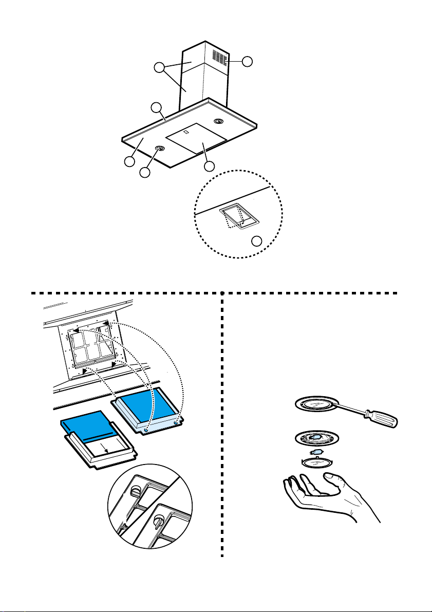
Description of the hood - Fig. 1
1 Control panel
2 Grease filter
3 Lamp
4 Vapour screen
5 Telescopic chimney
6 Air outlet (used for filter version only)
Operation
1234
1. on/off light switch
2. key OFF/ON suction and power selection of suction 1
2. + 3. power selection of suction 2
2. + 3. + 4.power selection of suction 3
Use the high suction speed in cases of concentrated kitchen vapours.
It is recommended that the cooker hood suction is switched on for 5
minutes prior to cooking and to leave in operation during cooking and
for another 15 minutes approximately after terminating cooking.
If the hood fails to operate correctly, briefly disconnect it from the
mains power supply for almost 5 sec. by pulling out the plug. Then plug
it in again and try once more before contacting the Technical Assistance
Service.
Maintenance
Prior to any maintenance operation ensure that the cooker hood is
disconnected from the power supply.
Cleaning the hood
The cooker hood should be cleaned regularly internally and externally.
For cleaning use a cloth moistened with denatured alcohol or neutral
liquid detergents. Avoid abrasive detergents.
Warning:
Failure to carry out the basic standards of the cleaning of the cooker
hood and replacement of the filters may cause fire risks.
Therefore we recommend oserving these instructions.
the chimney to the cooker hood (Fig. 2).
Insert the pad (i) of activated carbon into the frame (h) and fit the whole
back into its housing (j).
Replacing lamps - Fig. 3
Warning!
Prior to touching the light bulbs ensure they are cooled down.
1. Extract the guard by levering it off with a small screwdriver or
similar tool.
2. Replace the damaged light bulb.
Only use halogen bulbs of 20W max (G4), making sure you do not
touch them with your hands.
3. Close the lamp cover (it will snap shut).
If the lights do not work, make sure that the lamps are fitted
properly into their housings before you call for technical
assistance.
Caution
The appliance is not intended for use by young children or infirm
persons without supervision.
Young children should be supervised to ensure that they do not play
with the appliance.
WARNING - Ensure that the appliance is switched off before replacing
the lamp to avoid the possibility of electric shock.
Do not use the cooker hood where the grill is not correctly fixed! The
suctioned air must not be conveyed in the same channel used for
fumes discharged by appliances powered by other than electricity.
The environment must always be adequately aerated when the
cooker hood and other appliances powered by other than electricity
are used at the same time. Flambé cooking with a cooker hood is
prohibited. The use of a free flame is damaging to the filters and may
cause fire accidents, therefore free flame cooking must be avoided.
Frying of foods must be kept under close control in order to avoid
overheated oil catching fire. Carry out fumes discharging in accordance
with the regulations in force by local laws for safety and technical
restrictions.
Grease filter
This must be cleaned once a month using non aggressive detergents,
either by hand or in the dish-washer, which must be set to a low
temperature and a short cycle.
When washed in a dish-washer, the grease filter may discolour
slightly, but this does not affect its filtering capacity.
To remove the grease filter, pull the spring release handle (f) - (Fig. 1).
Charcoal filter (filter version only)
It absorbs unpleasant odours caused by cooking.
The charcoal filter can be washed once every two months using hot
water and a suitable detergent, or in a dish-washer at 65°C (if the dishwasher is used, select the full cycle function and leave dishes out).
Eliminate excess water without damaging the filter, then remove the
mattress located inside the plastic frame and put it in the oven for 10
minutes at 100° C to dry completely. Replace the mattress every 3
years and when the cloth is damaged.
Remove the filter holder frame by turning the knobs (g) 90° that affix
7
Page 7

After Sales Service
"No company is better positioned to offer an after sales service on a
Hotpoint appliance than us - the manufacturer"
As part of our commitment to you, all Hotpoint appliances have the added benefit of a fully inclusive
parts and labour guarantee for the first 12 months. In addition to this you also have the advantage of
engineer. When the 12 months parts and labour guarantee expires we offer the following after sales
Note: Our operators will require the Model number and the Serial number of your appliance
Available 364 days a year with a fast, effective and value for money service. We have the largest
white goods repair service in the UK with over 1000 of our own fully trained engineers. All repairs
If you require any information or have any questions about your appliance, our operators are on hand
Whether you have just one or a number of Hotpoint appliances in your kitchen, we offer two service
●
Repair Protection Plan - FREE service repairs for a single Hotpoint appliance during the
●
Kitchen Cover - FREE service repairs for all your Hotpoint appliances less than
free replacement parts for the first 5 years when fitted by a Hotpoint
service options:
Repair Service and Information Help Desk
UK: 08709 066066
www.hotpointservice.co.uk
Republic of Ireland: 1850 302 200
include a parts and labour guarantee for 12 months from the date of the repair.
with help and advice.
All this ensures that you will receive the best available after sales service possible.
Extended Warranties
UK: 08709 088 088
www.hotpointservice.co.uk
Republic of Ireland: 1850 502 200
cover plans to give you total peace of mind.
period of cover.
8 years old.
Genuine Parts and Accessories
UK: 08709 077 077
www.hotpointservice.co.uk
A wide range of genuine parts and accessories are available from our hotline or through our website.
Genuine parts and accessories, extended warranties and service repairs are all
GB91 0
Republic of Ireland: (01) 842 6836
available on our web-site at:
7
Page 8

Key Contacts
After Sales Service
Over 1200 trained specialists, directly employed by us, ensure that you can have complete
confidence in both the appliances and services we offer.
Repair Service and Information Desk
(Open 8 to 8 Mon - Fri, 8 to 6 Sat, 10 to 4 Sun & Bank Holidays)
Republic of Ireland: 1850 302 200
Note: Our operators will require the following information:
Republic of Ireland: 1850 502 200
Genuine Parts and Accessories
(Open 8-30 to 5-30 Mon - Fri & 9 to 12 Sat)
RepublicofIreland:(01)8426836
UK: 08709 066 066
www.hotpointservice.co.uk
Model number:
Serial number:
Extended Warranties
UK: 08709 088 088
(Open 8 to 8 Mon - Sun)
www.hotpointservice.co.uk
UK: 08709 077 077
www.hotpointservice.co.uk
Merloni Elettrodomestici UK Ltd., Morley Way , Peterborough, PE2 9JB
LI2JDA Ed. 11/04
 Loading...