

Page 1

Avvertenze
1 Questo apparecchio è stato concepito per un uso
di tipo non professionale all'interno di abitazione.
2 Prima di utilizzare l’apparecchio, leggere attenta-
mente le avvertenze contenute nel presente libretto in quanto forniscono importanti indicazioni riguardanti la sicurezza di installazione, d’uso e di
manutenzione. Conservare con cura questo libretto
per ogni ulteriore consultazione.
3 Dopo aver tolto l’imballaggio assicurarsi dell’integrità
dell’apparecchio. In caso di dubbio non utilizzare l’apparecchio e rivolgersi a personale professionalmente
qualificato. Gli elementi dell’imballaggio (sacchetti in
plastica, polistirolo espanso, chiodi, ecc.) non de vono
essere lasciati alla portata dei bambini in quanto potenziali fonti di pericolo.
4 L’installazione deve essere eff ettuata secondo le istru-
zioni del costruttore da personale professionalmente
qualificato. Una errata installazione può causare danni a persone, animali o cose, nei confronti dei quali il
costruttore non può essere considerato responsabile.
5 La sicurezza elettrica di questo apparecchio è assicu-
rata soltanto quando lo stesso è correttamente collegato ad un efficiente impianto di messa a terra come
previsto dalle vigenti norme di sicurezza elettrica. E’
necessario verificare questo fondamentale requisito di
sicurezza e, in caso di dubbio, richiedere un controllo
accurato dell’impianto da parte di personale professionalmente qualificato. Il costruttore non può essere
considerato responsabile per eventuali danni causati
dalla mancanza di messa a terra dell’impianto.
6 Prima di collegare l’apparecchio accer tarsi che i dati
di targa siano rispondenti a quelli della rete di distribuzione elettrica.
7 V erificare che la portata elettrica dell’impianto e delle
prese di corrente siano adeguate alla potenza massima dell’apparecchio indicata in targa. In caso di dubbio rivolgersi ad una persona professionalmente qualificata.
8 All’installazione occorre prevedere un interruttore
omnipolare con distanza di apertura dei contatti uguale o superiore a 3 mm.
9 Questo apparecchio dovrà essere destinato solo al-
l’uso per il quale è stato espressamente concepito.
10 Ogni altro uso (ad esempio: riscaldamento di ambien-
ti) è da considerarsi improprio e quindi pericoloso.
11 Il costruttore non può essere considerato responsabi-
le per eventuali danni derivanti da usi impropri, erronei
ed irragionev oli.
12 L’uso di un qualsiasi apparecchio elettrico comporta
l’osservanza di alcune regole fondamentali. In particolare:
• non toccare l’apparecchio con mani o piedi bagnati o
umidi
• non usare l’apparecchio a piedi nudi
• non usare, se non con particolare cautela, prolunghe
• non tirare il cavo di alimentazione, o l’apparecchio stes-
so, per staccare la spina dalla presa di corrente.
• non lasciare esposto l’apparecchio ad agenti atmosfe-
rici (pioggia, sole, ecc.)
• non permettere che l’apparecchio sia usato dai bam-
bini o da incapaci, senza sorveglianza
13 Prima di effettuare qualsiasi operazione di pulizia o di
manutenzione, disinserire l’apparecchio dalla rete di
alimentazione elettrica, o staccando la spina, o spegnendo l’interruttore dell’impianto.
14 Se si dovessero v erificare fratture sulla superficie del
vetro, scollegare immediatamente l’apparecchio. Per
la riparazione rivolgersi solamente ad un centro di assistenza tecnica autorizzato e richiedere l’utilizzo di
ricambi originali. Il mancato rispetto di quanto sopra
può compromettere la sicurezza dell’apparecchio.
15 Allorchè si decida di non utilizzare più l’apparecchio,
si raccomanda di renderlo inoperante tagliandone il
cavo di alimentazione, dopo a ver staccato la spina dalla
presa di corrente. Si raccomanda inoltre di rendere innocue quelle parti dell’apparecchio suscettibili di costituire un pericolo, specialmente per i bambini che potrebbero servirsi dell’apparecchio fuori uso per i propri
giochi.
16 Il piano in vetroceramica è resistente agli sbalzi di
temperatura e agli urti. T uttavia se colpito con oggetti come taglierini o utensili con bordi appuntiti
può rompersi. In questo caso togliete subito l’alimentazione e rivolgetevi ad un centro di assistenza autorizzato.
17 Non dimenticate che la zona di cottura rimane calda
per almeno mezz’ora dopo lo spegnimento. Fate attenzione a non appoggiare inavvertitamente recipienti
o oggetti sulla zona ancora calda.
18 Non accendete le zone di cottura se ci sono fogli di
alluminio o materiali plastici sul piano
19 Non avvicinatevi alle zone di cottur a calde
20 Usando piccoli elettrodomestici nelle vicinanze del pia-
no fate attenzione che il cav o di alimentazione non finisca su parti calde
21 Fate attenzione che i manici delle casseruole siano
orientati verso l’interno, del piano per evitare di urtarli
accidentalmente.
22 Non lasciare mai una zona di cottura accesa senza
che vi sia una pentola sopra, perchè in tal caso il riscaldamento sarà massimo in brevissimo tempo , con
possibili danni per gli elementi riscaldanti.
23 A vvertenza prima dell’utilizzazione iniziale. La col-
la utilizzata per la sigillatura del vetro può lasciare delle tracce di grasso. Vi consigliamo di eliminarle prima
dell’uso dell’apparecchio, con un prodotto per pulizia
non abrasivo. Durante le prime ore di utilizzazione, si
può avvertire un odore di gomma, che sparirà rapidamente.
2
Page 2
Installazione
Le istruzioni che seguono sono rivolte all’installatore qualificato affinchè compia le operazioni di installazione
regolazione e manutenzione tecnica nel modo più corretto e secondo le norme in vigore.
Importante: qualsiasi intervento di regolazione, manutenzione etc. de ve essere eseguito con il piano elettricamente disinserito.
Installazione dei piani da incasso
I piani sono predisposti con grado di protezione contro i
riscaldamenti eccessivi di tipo X secondo la norma CEI
335-2-6, non è pertanto possibile l’installazione a fianco
di mobili la cui altezza superi quella del piano di lavoro.
Per una corretta installazione del piano di cottura vanno
osservate le seguenti precauzioni:
a) La cappe debbono essere installate secondo i requisi-
ti richiesti nei libretti istruzioni delle cappe stesse.
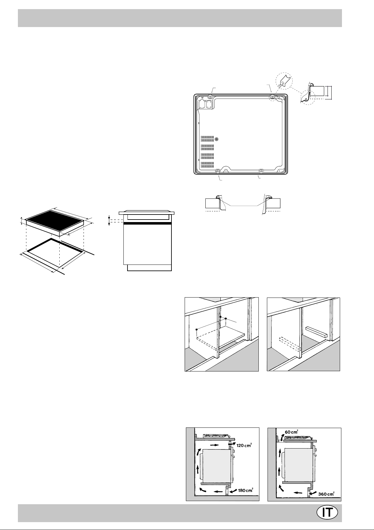
b) Il piano Vetroceramica da incasso può essere installa-
to su qualsiasi Top profondo 600 mm o più, purchè si
tratti di materiale resistente a temperature di 100°C.
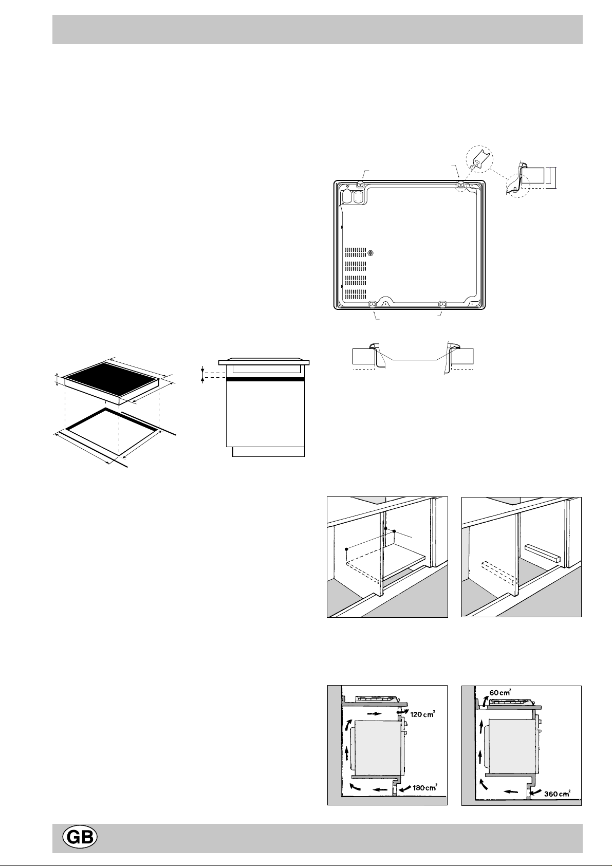
Le dimensioni e la posizione del foro sono illustrati nella
figura.
595
ri o le viti Torx posteriori.
E ' quindi indispensabile che queste viti restino
accessibili.
Inserire il piano nel foro premendo bene intorno la
cornice per far aderire il piano al Top.
MONTAGGIO DELLE MOLLE DI FONDO
FISSAGIO POSTERIORE SINISTRO
FISSAGIO POSTERIORE DESTRO
PIANO A ROVESCIO
FISSAGIO ANTERIORE DESTRO
MONTAGGIO DELLA GUARNIZIONE
ANTERIORE / POSTERIORE DESTRA / SINISTRA
Materiale
spugnoso 5x8 mm
FISSAGIO ANTERIORE SINISTRO
PARTE ANTERIORE DEL PIANO
TOP DEL
30
MOBILE
40
48
560 +/- 1
510
490 +/- 1
20
Distanza da rispettare
fra il vano per
l'incasso
e il mobile
X (CEI 335-2-6)
Le suddette misure vanno assolutamente rispettate in
quanto un’installazione scorretta può causare
surriscaldamenti delle superfici circostanti.
Si raccomanda tenere il piano di cottura a distanza
minima di 40mm. dalla parete posteriore o da altre superfici verticali per consentire la regolare circolazione
d’aria ed evitare surriscaldamenti delle superfici circostanti. Con il piano cottura viene f ornita una guarnizione. Assicurarsi che essa aderisca alla parte sottostante
della cornice del piano. E ’ indispensabile che la guar-
nizione arrivi bene agli angoli e avvolga il piano in modo
da creare una corretta tenuta tra il Top e il piano stesso per impedire che eventuali trabocchi filtrino nel
mobile sottostante.
Importante : é indispensabile che l'incasso del piano
vetroceramica venga eff ettuato su una superficie d'appoggio perfettamente piana. Le deformazioni indotte da un
cativo fissagio rischiano di alterare le caratteristiche del
piano di cottura e le sue prestazioni.
c) Nel caso in cui sotto il piano venga installato un
pannello di legno come isolamento, esso dovrà essere posizionato ad una distanza minima di 20 mm. dalla
parte inferiore del piano stesso.
Nota: Nel caso in cui il piano sia installato su di un forno
incasso, è preferibile installare il forno in modo che appoggi su due listelli in legno; nel caso in cui sia presente
un piano continuo di appoggio questo dev e avere un’aper-
tura posteriore di almeno 45 x 560 mm.
45 mm.
560 mm.
Nel caso di installazione sopra un forno da incasso senza
ventilazione forzata di raffreddamento, per consentire
un’adeguata areazione all’interno del mobile vanno garantite delle prese d’aria di ingresso e di uscita. Possibili
esempi di montaggio sono illustrati nelle figure sottostanti.
Accertatevi che la guarnizione che circonda il bordo
del piano di cottura sia ben posizionata allo scorpo di
evitare eventuali infiltrazioni nel mobile di sostegno.
Le molle di fissagio sono avvitate con viti TORX.
Per rimuov ere il pianon, occorre svitare le viti Torx anterio-
3
Page 3
Caratteristiche tecniche
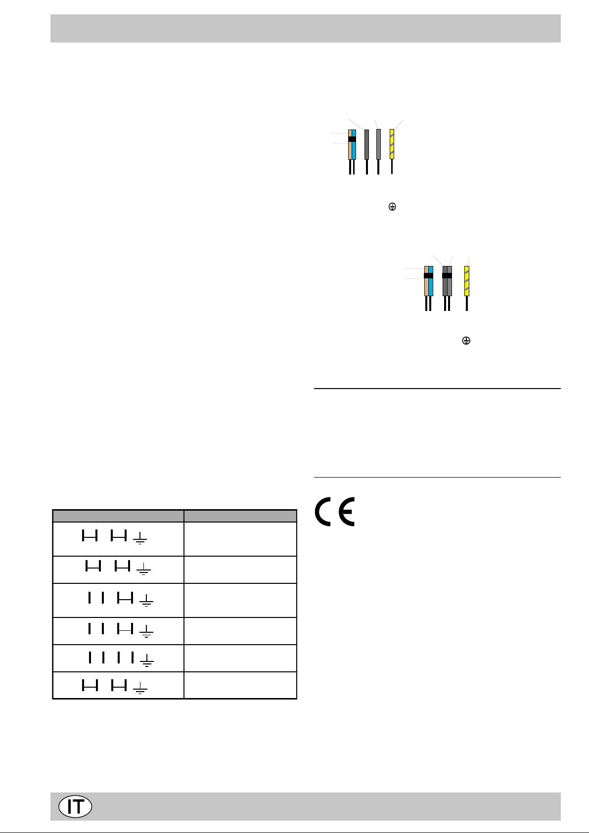
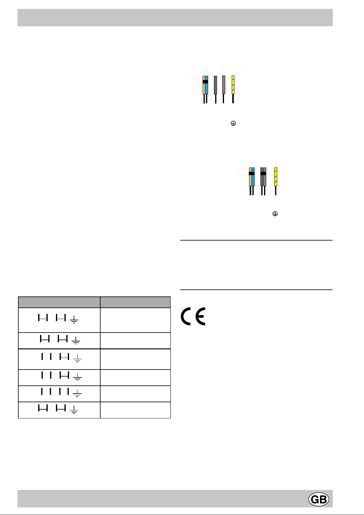
NERO
NERO
VERDE / GIALLO
BLU
BRUNO
NL
Neutro
Fase
Terra
Collegamento monofase
accopiate i 2 fili
neri per la fasa
Collegamento elettrico
· La sicurezza elettrica di questo apparecchio é garanti-
ta unicamente se é stato effettuato il collegamento a
terra conformemente alle norme di sicurezza elettrica.
Il fabbricate declina ogni responsabilità relativ a a danni
derivanti da un'installazione di messa a terra difettosa.
· Importante
Il piano di cottura viene consegnato con un cavo di
collegamento specifico ARISTON.
Qualora venisse danneggiato , il cavo dev e essere sostituito da un tecnico autorizzato.
Prima di qualsiasi intervento, disinserite la spina dell'apparecchio dalla presa di corrente.
Montare sul cavo una spina normalizzata per il carico indicato sulla targhetta caratteristiche, nel caso di collegamento diretto alla rete è necessario interporre tra l’apparecchio e la rete un interruttore omnipolare con apertura
minima fra i contatti di 3 mm. dimensionato al carico e
rispondente alle norme in vigore (il filo di terra non deve
essere interrotto dall’interruttore). Il cavo di alimentazione deve essere posizionato in modo che non raggiunga
in nessun punto una temperatura superiore di 50°C a
quella ambiente. Prima di effettuare l’allacciamento accertarsi che:
• la valvola limitatrice e l’impianto domestico possano
sopportare il carico dell’apparecchiatura (vedi targhetta
caratteristiche);
• l’impianto di alimentazone sia munito di efficace colle-
gamento a terra secondo le norme e le disposizioni di
legge;
• la presa o l’interruttore omnipolare siano facilmente
raggiungibili con il piano installato.
Accopiamenti
- Collegate i 5 fili sul vostro apparecchio rispettando il
colore dei fili e gli accopiamenti.
NERO
NERO
VERDE / GIALLO
BLU
BRUNO
Fase 1
Fase 2
Neutro
N
L1
Collegamento bifase
Assorbimento Max:
KM 6000 Q 6200W
KM 6001 H 6400W
KM 6002 H 6500W
L2
Terra
Collegamento e le ttrico Tenzione di alimenta zione
N
L
NOIR
L1
NOIR
L1
NOIR
L1
NOIR
L1
NOIR
L
NOIR
* A pplicazione del coeff iciente di simultaneità in conf ormi-
BLBR
L2
BLBR
N
L2
BLBR
L3
L2
BLBR
N 1
L2
N 2
BLBR
N
BLBR
N:Nero, BR:Bruno, BL:Blu
AT-FR-BE-DE-GP-ES-IE-IL-IS-IT-
LU-RE-GR-PT-SE-MA-NZ-GB-DK-NL
230 V - 1 + N ~ 5 0 Hz
Fusibile 20 A*
FR - BE - NO
230 V - 2 ~ 50 Hz
Fusibile 20 A*
AT-FR-BE-CH-DE-ES-IL-IS-IT-LU
PT-SE-MA-NZ-DK-NL
400 V - 2 + N ~ 5 0 Hz
Fusibile 16 A*²
FR - BE -NO
230 V - 3 ~ 50 Hz
Fusibile 20 A*
NL
230 V - 2 +2N ~ 50 Hz
Fusibile 16 A*
CY-MT-AU-KW
240 V - 1 + N ~ 5 0 Hz
Fusibile 20 A*
tà con la norma EN 335-2-6
Collegamento elettrico di tipo Y in conformità con al norma
EN 335-2-6
Questa apparecchiatura è conforme alle seguenti
Direttive Comunitarie:
- 73/23/CEE del 19/02/73 (Bassa Tensione) e successive modificazioni;
- 89/336/CEE del 03/05/89 (Compatibilità Elettromagnetica) e successive modificazioni;
- 93/68/CEE del 22/07/93 e successive modificazioni.
Attenzione: Nel caso di installazione sopra un forno da
incasso l’allaccio elettrico del piano e quello del forno deve
essere realizzato separatamente, sia per ragioni di sicurezza elettrica che per facilitare l’ev entuale estraibilità del
forno.
4
Page 4
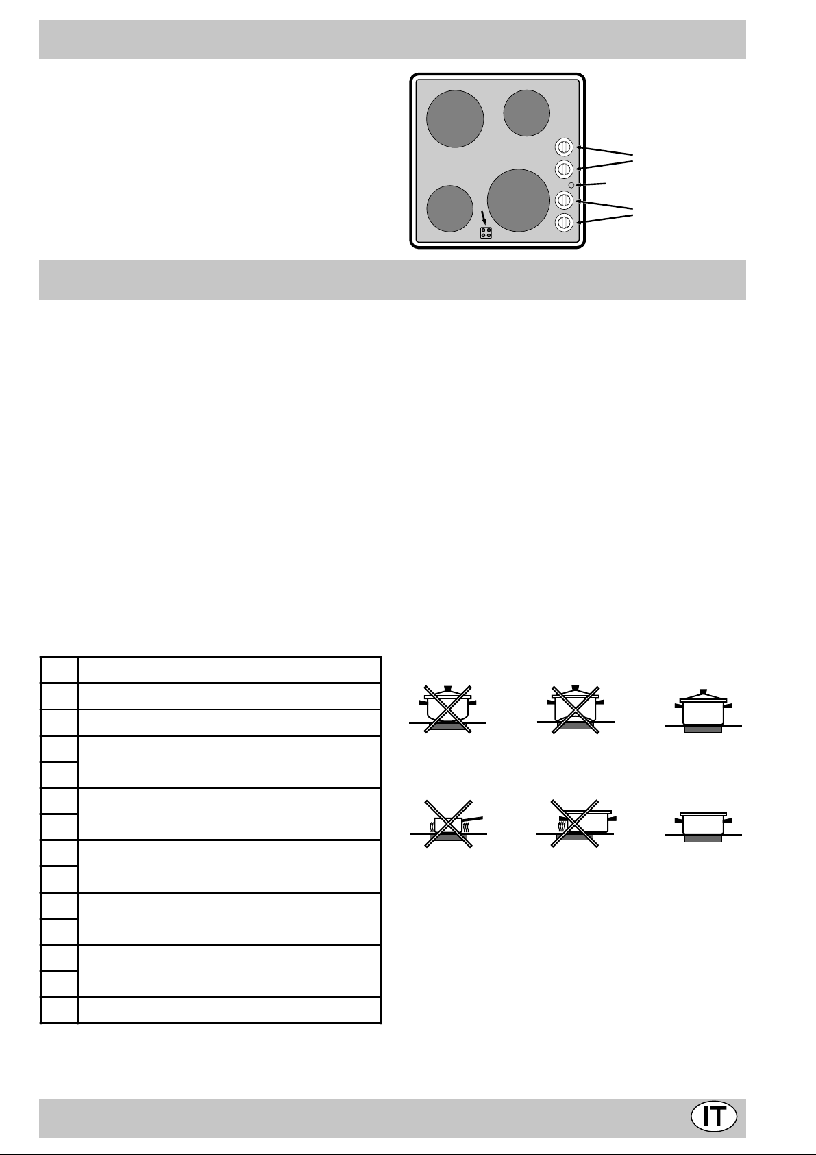
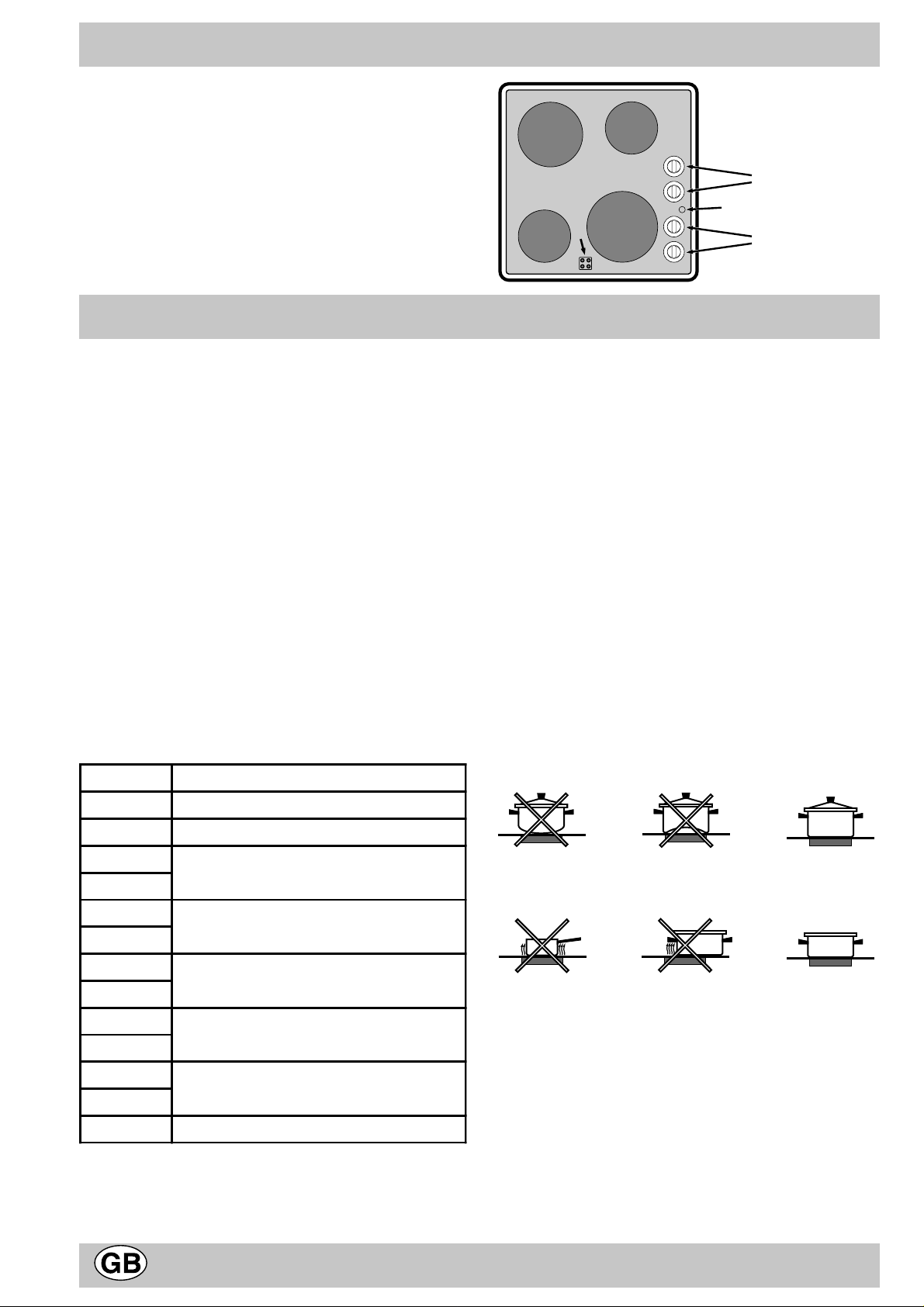
Descrizione del piano di cottura
A Zone di cottura
B Spia funzionamento
C Manopole di comando
D Spie calore residuo
Le diverse funzioni presenti nel piano
Descrizione degli elementi riscaldanti
Gli elementi radianti sono composti da resistenze circo-
lari. Diventano rossi solo dopo alcune decine di secondi
dalla loro accensione.
Gli elementi alogeni misti. Il piano utilizza degli elementi composti da due lampade alogene e da una resistenza
circolare. Grazie a questa combinazione si ottiene una
distribuzione di temperatura ottimale su tutta la superficie
della zona di cottura, pur mantenendo tutti i vantaggi delle lampade alogene. Le lampade alogene hanno come
caratteristica principale l’emissione istantanea di una grande quantità di luce e di calore, in pratica:
• riscaldamento rapido simile a quello di un bruciatore a
gas
• uno spegnimento altrettanto rapido
Il loro utilizzo è estremamente semplice in quanto analogo a quello degli altri elementi riscaldanti. F ate riferimento alla tabella 1.
T abella 1
Pos. Piastra automatica
A
D
A
A
0
1
2
1
1
1
2
10
3
9
4
8
5
7
6
0
1
2
1
1
1
2
10
3
9
4
8
5
7
6
0
1
2
1
1
1
2
10
3
A
9
4
8
5
7
6
0
1
2
1
1
1
2
10
3
9
4
8
5
7
6
C
B
C
Le manopole di comando
Ciascuna zona di cottura è dotata di una manopola di
comando che permette una regolazione continua di temperatura da un minimo di 1 ad un massimo di 12. Nella
tabella 1 seguente sono riportate le corrispondenze fra le
posizioni indicate sulla manopola e l’uso per il quale le
piastre sono consigliate.
La spia di funzionamento (B)
Risulta accesa quando sia stata messa in funzione una
zona riscaldante.
La spia calore residuo (D)
Indica che, una o più zone di cottura, sono a temperatura
superiore a 60°C anche dopo lo spegnimento delle zone
di cottura. Alcuni modelli sono dotati di 4 spie calore residuo, una per ogni zona di cottur a.
Avvertenze per l’uso del piano vetroceramica
Per ottenere i migliori risultati dal vostro piano di cottur a,
esistono alcuni accorgimenti fondamentali da seguire durante la cottura o nella preparazione dei cibi.
• Adoperare pentole con fondo piatto per essere certi
dell’aderenza della pentola alla zona di cottura.
0
Spento
1
Per sciogilere burro, cioccolata
2
Per riscaldare liquidi
3
4
Per creme e salse
5
6
Per cuocere alla temperatura di ebollizione
7
8
Per arrosti
9
10
Per grandi lessi
11
12
Per Friggere
• Adoperare pentole di diametro sufficiente a coprire
completamente la piastra di cottura, in modo da garantire l’utilizzazione di tutto il calore disponibile.
• Accertatevi che la base delle pentole sia sempre asciut-
ta e pulita, per garantire un buon contatto ed una lunga durata delle piastre e delle pentole stesse.
• Non adoperare le stesse stoviglie utilizzate per bru-
ciatori a gas. La concentr azione del calore sui bruciatori a gas è tale che può deformare il fondo della pentola, e pertanto non si otterrà mai il risultato desiderato adoperandola poi sul piano cottura in V etroceramica.
• Non lasciare mai una zona di cottura accesa senza
che vi sia una pentola sopra, perché in tal caso il riscaldamento sarà massimo in brevissimo tempo, con
possibili danni per gli elementi riscaldanti.
5
Page 5
• Non dimenticate che la zona di cottura rimane calda
per almeno mezz’ora dopo lo spegnimento; f ate attenzione a non appoggiare inavvertitamente recipienti o
oggetti sulla zona ancora calda.
• Non accendete le zone di cottura se ci sono fogli di
alluminio o materiali plastici sul piano.
• Non avvicinatevi alle zone di cottur a calde .
Il Vetroceramica con cui è fatto il piano cottura è molto
resistente. Tuttavia se si dovesse fratturare non adoperare il piano cottura. staccate la corrente .
Pulizia e Cura
• Avvertenza prima dell’utilizzazione iniziale:
la colla utilizzata per le guarnizioni depone, durante il
periodo di stoccaggio, delle tracce di grasso sul v etro .
Vi consigliamo di eliminarle prima dell’uso dell’apparecchio, con un prodotto di pulizia abituale (crema lucidante non abrasiva). Durante le prime ore di utilizzazione, si sente un odore di gomma, che sparisce rapidamente.
• Il piano vetroceramica è resistente agli sbalzi di tem-
peratura ed agli urti. Tuttavia se colpito con oggetti
appuntiti può rompersi. In questo caso togliete subito
l’alimentazione e rivolgetevi ad un centro di assistenza tecnica autorizzato per la riparazione.
Mantenete sempre il piano pulito. Prima di pulirlo assicuratevi che il piano sia spento e che sia freddo.
Cornice in acciaio inox (solo su alcuni modelli)
L’acciaio inox può rimanere macchiato se a contatto per
lungo tempo con acqua fortemente calcarea o con detergenti aggressivi (contenenti fosf oro). Si consiglia di sciacquare abbondantemente ed asciugare dopo la pulizia. E’
inoltre opportuno eliminare eventuali trabocchi d’acqua.
Pulizia del piano di cottura
Prima di iniziare a cucinare, la superficie del piano deve
essere pulita usando un panno umido per rimuovere polvere o residui di cibi cotti precedentemente. La superficie
del piano dovrà essere pulita regolarmente con una soluzione di acqua tiepida e detergente non abrasivo.
Periodicamente sarà necessario usare dei prodotti specifici per la pulizia dei piani di cottura in vetroceramica.
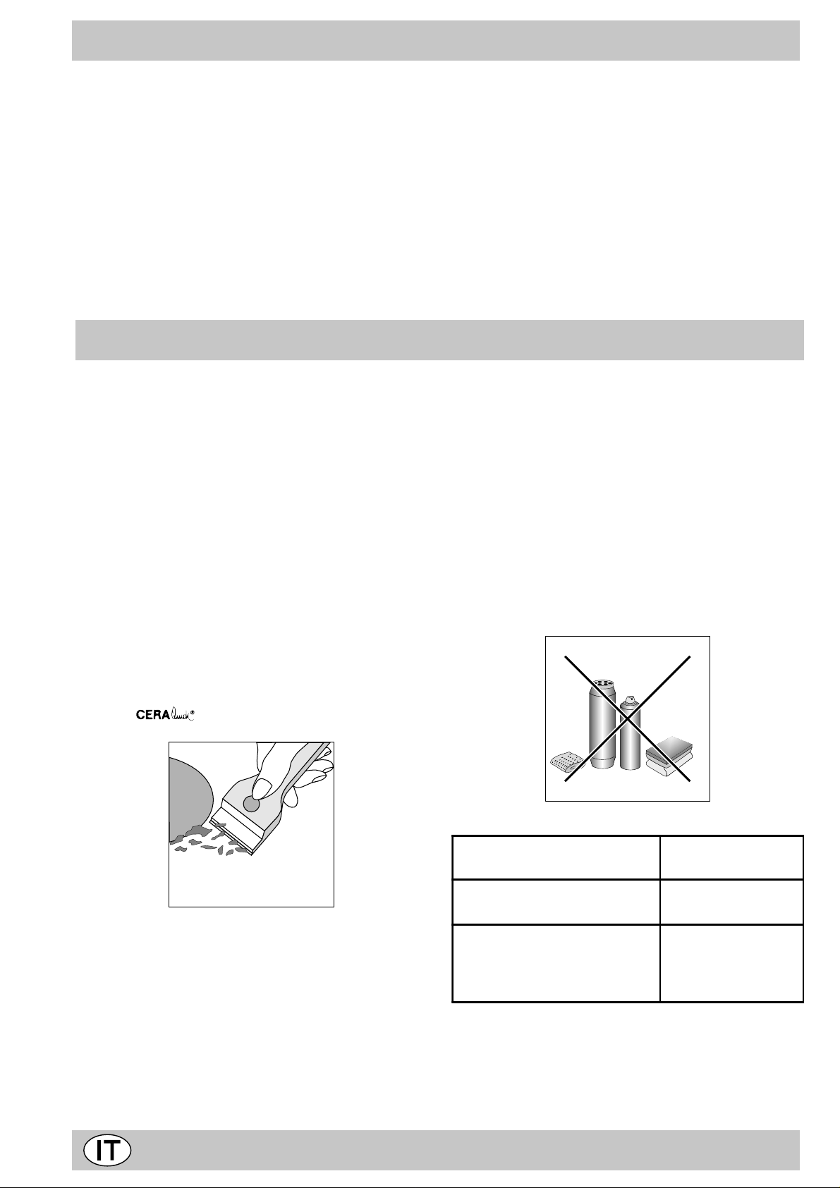
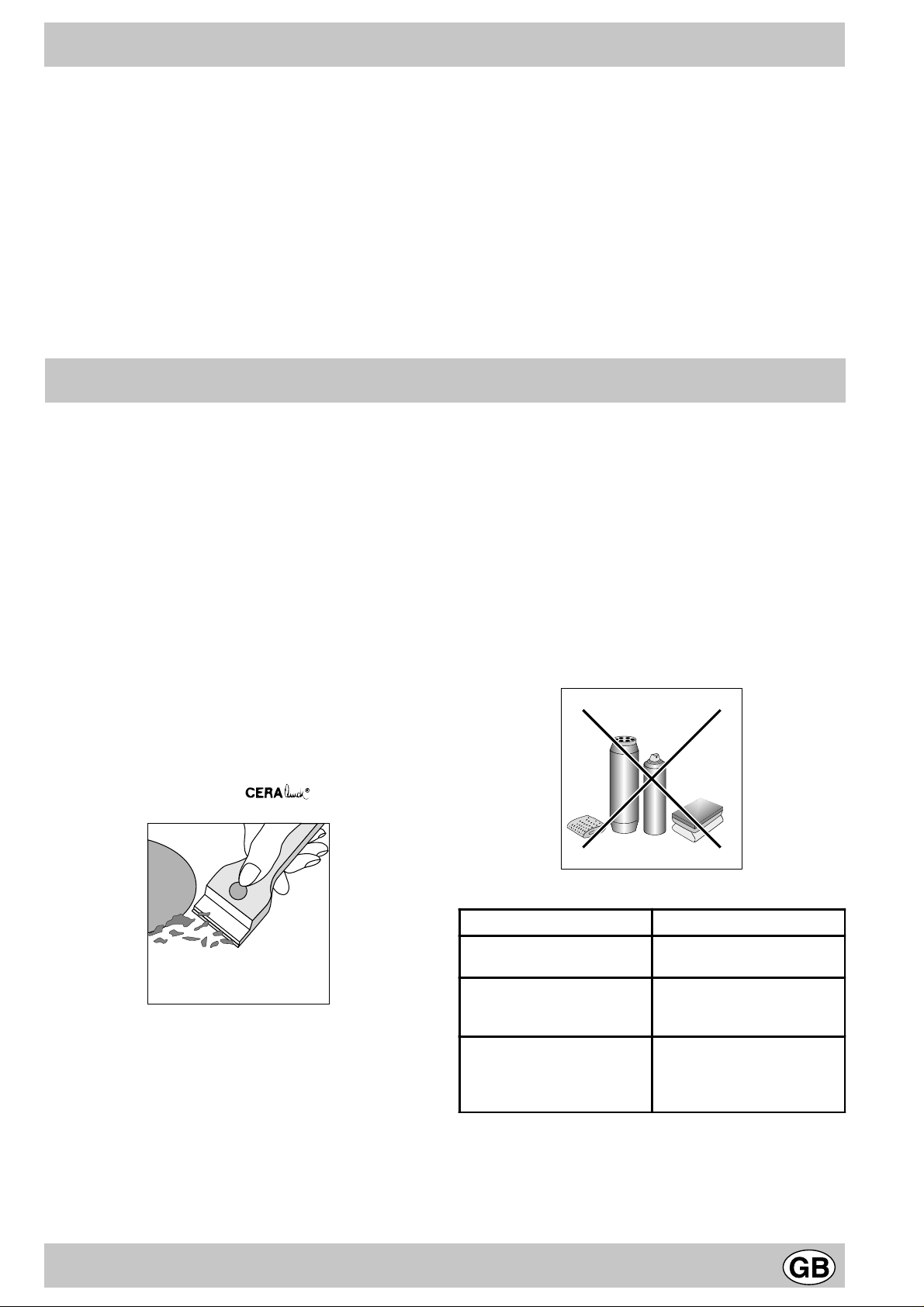
Dapprima togliere dal piano di cottura tutti i resti di vivande e spruzzi di grasso con un raschietto per la pulizia per
esempio (non in dotazione).
Pulire il piano di cottura quando è tiepido; utilizzare un
prodotto di pulizia adatto e carta da cucina, strofinare con
un panno umido ed asciugare. Fogli di alluminio, oggetti
in plastica o materiale sintetico, che si siano accidentalmente liquefatti, come pure lo zucchero o vivande ad alto
contenuto zuccherino vanno eliminati immediatamente
dalla zona di cottura ancora calda con un raschietto.
Prodotti di pulizia specifici formano uno strato superficiale trasparente repellente allo sporco. Questo protegge
anche la superficie da eventuali danni causati da viv ande
ad alto contenuto zuccherino. In nessun caso utilizzare
spugne o prodotti abrasivi, anche detersivi chimicamente
aggressivi come gli spray da f orno o prodotti smacchianti
vanno evitati.
Prodotti specifici pe r la puliz ia
del v etroceramica
Raschietto a lametta e Lamette
di ricambi
Stahl-Fix
SWISSCLEANER
WK TOP
Altri prodott i per vetroceramica
6
Dove a cquista rli
Hobbistica e
Ferram en t a
Casalinghi
Fai-Da-Te
Ferram en t a
Supermercati
Page 6

Instructions
1 This appliance is intended for non-professional use
within the home.
2 Before using the appliance, carefully read the
instructions contained in this manual, as they
provide important information for ensuring safe
installation, use and maintenance. Keep this
manual as a reference guide.
3 After the packing has been removed, make sure the
appliance has not been damaged during transport. If
you have any doubts, do not use the appliance . Call a
qualified technician for assistance. For saf ety purposes,
keep all packing materials (plastic bags, polystyrene
foam, tacks, etc.) away from children, as they are a
potential source of injury.
4 The appliance must be installed by a qualified
technician in accordance with the manufacturer’s
instructions. Improper installation due to a failure to
follow these instructions can cause injury or damage
to persons, animals or property . The manufacturer will
not be held liable for such damages .
5 The appliance’s electrical system is safe and secure
only when it is correctly connected to an appropriately
earthed system which complies with electrical safety
regulations. Make sure this basic safety requirement
has been complied with. If in doubt, ha ve it checked b y
a qualified technician. The manuf acturer will not be held
liable for damages caused b y the improper earthing of
the appliance.
6 Before connecting the appliance, make sure the
specifications on the rating plate correspond to those
of your power supply.
7 Make sure that the current of the electrical system and
the outlets are sufficient for the maximum rated output
indicated on the rating plate. If in doubt, contact a
qualified technician for assistance.
8 A multipolar switch, with a contact break of 3 mm or
more, must be fitted for installation.
9 This appliance must only be used for the purpose for
which it was designed.
10 All other uses (for heating f or example) are considered
improper and, therefore, dangerous.
11 The manufacturer will not be held liable for damages
arising from improper, incorrect, or unreasonable use .
12 When using electrical appliances, the following basic
rules must be observed:
• never touch the appliance when y our hands or feet are
wet.
• never use the appliance if y ou are baref oot.
• use extensions, if necessary, with extreme caution.
• never pull the supply cord, or the appliance itself, to
disconnect the plug from the electrical socket.
• never lea ve the appliance exposed to the weather (r ain,
sun, etc.)
• never let children or persons unfamiliar with the
appliance use it without appropriate supervision.
13 Before doing any cleaning or maintenance work on the
appliance, disconnect it from the supply mains, either
by removing the plug from the sock et, or by turning off
the power at the mains.
14 If the glass surface of the cooktop cracks or breaks,
disconnect the appliance immediately from the power
supply. For repairs contact only authorised service
centres for assistance and make sure only original
spare parts are used. Failure to do so could impair the
safety of the appliance.
15 If you decide not to use the appliance any longer , make
it unserviceable by unplugging the appliance from the
mains and cutting the supply cord. Mak e any potentially
dangerous parts safe, this precaution is particularly
important for protecting children who might play with,
or in, unused or abandoned appliances.
16 The top made of ceramic glass is resistant to
sudden temperature changes and shocks.
However, if it is struck with pointed utensils or
objects such as cutting knives, it ma y crack or break. If this occurs, disconnect the appliance
immediately from the power supply and contact
an authorised service centre.
17 Keep in mind that the cooking area remains hot f or at
least a half an hour after the appliance has been turned
off. Make sure that you do not inadvertently place
containers or objects on the cooking area while it is
still hot.
18 Do not turn the heating elements on if there are plastic
objects or aluminium foil on the cooktop.
19 Do not get too close to the cooking areas when they
are hot.
20 When using small electrical appliances near the
cooktop, make sure that the supply chord does not
come into contact with those parts of the appliances
which are hot.
21 Make sure that the handles on pots and pans are turned
inward to prev ent bumping them accidentally.
22 Never leave a cooking element on unless element is
placed on the element because the cookware will
become very hot in a short period of time and this may
damage the heating elements.
23 Instructions for using the appliance the fir st time.
The glue used to seal the glass may leave grease
residues. We recommend that these residues be
removed with a non-abrasiv e cleaning product bef ore
the appliance is used. During the first f ew hours of use,
you may detect the odour of rubber . However , this will
disappear quickly.
7
Page 7
Installation
FRONT RIGHT MOUNTING
FRONT LEFT MOUNTING
SEAL MOUNTING
FRONT / REAR RIGHT / LEFT
MOUSSE 5x8 mm
HOB UNIT FACE DOWN
REAR RIGHT MOUNTING
WORK
SURFACE
REAR SPRING ASSEMBLY
FRONT OF THE HOB UNIT
30
40
REAR LEFT MOUNTING
560 mm.
45 mm.
These instructions are intended for the qualified technician
installing the appliance in order to insure that the
installation, adjustments and maintenance procedures are
performed correctly and comply with the regulations
currently in effect.
Important: the cooktop must be disconnected from
the power supply before making any adjustments or
performing any maintenance, etc.
Installing built-in cooktops
The cooktops have a type X protection rating against
overheating in compliance with regulation CEI 335-2-6.
Therefore, the cooktops cannot be installed alongside of
cabinets which are higher than the surface of the cooktop
itself. The following precautionary measures should be
observed in order to ensure proper installation:
a) Hoods must be installed in compliance with the required
specifications contained in the instruction manual for
the hood itself.
b) The built-in ceramic glass top can be installed on any
counter top as long as it is 600 mm or more in width
and resistant to temperatures of up to 100°C.
The dimensions and the position of the hole are shown
in fig..
595
20
48
560 +/- 1
510
490 +/- 1
Leave this much
space between
the bottom and
the cabinetry
X (CEI 335-2-6)
The four securing springs are held in place by 4 Torx
screws.
To remove the hob unit from its housing, undo the 2 Torx
screws at the front, then the 2 Torx screws at the rear.
The 4 screws should be accessible at all times for this
purpose.
c) If a wooden panel is installed beneath the cooktop
for insulation purposes, it must be positioned at least
20 mm from the bottom part of the cooktop itself.
Note: If the cooktop is installed above a b uilt-in ov en, it is
preferable that the o ven be installed in such a way that it
is set on two strips of wood; if, on the other hand, the o ven
is installed on a continuous base, there must be an opening
in the back of at least 45 x 560 mm.
The aforementioned measurements must absolutely
be observed in so far as improper installation can cause the surrounding surface areas to overheat.
It is recommended that the cooktop be installed at a
distance of at least 40 mm from the back wall or other
vertical surfaces to ensure that the air circulates
properly over the cooking area and to av oid overheating
the surrounding surfaces. A seal or gask et is provided
with the cooktop; mak e sure that it adheres properly to
the bottom part of the frame of the cooktop.
It is indispensable that the seal fits properly around
the entire cooktop frame and especially along the
corners in order to create a seal between the counter
top and the cooktop itself so as to prevent spills or
splashes from leaking into the cabinet below .
Very important
It is essential to install the hob on a totally flat surtace. Any
damage caused by incorrect fitting may alter the
characteristics or impair performance.
Insert the cooktop into the hole, pressing firmly around
the frame to make it adhere to the counter top .
Make certain that the seal around the outside edge of
the hob is correctly installed in order to avoid any
leakage into the cabinetry below.
If the cooktop is installed above a built-in oven not
equipped with a forced air cooling system, air intake and
exhaust slots must be provided to ensure that the air
circulates properly within the cabinet. Figures provide
illustration of possible installation solutions.
8
Page 8
Technical specifications
Electrical connection
· The electrical safety ot this appliance is guaranteed
only if the appliance is correctly earthed in
compliance with the standards of electrical safety.
The manufacturer can under no circumstances be
considered responsible for an y damage that might occur
due to incorrect earthing of the appliance.
· Important points
Your hob unit is supplied with a special Scholtès
connection cable.
If ever the cab le is damaged, it should be replaced by an
authorised service engineer only.
Disconnect the appliance before any work is carried
out.
· Fasten the appropriate standard plug for the load
indicated the rating plate to the chord. If the appliance
must be directly connected to the mains, a multipolar
switch must be installed between the appliance and the
mains. The multipolar switch must have a minimum of
3 mm of space between the contacts, be sized to the
load, and comply with current regulations (the switch
must not be able to disconnect the earth conductor).
The supply cord must be positioned so that no part of it
reaches a temperature of 50 °C higher than room temperature. Before making the connection, make sure that:
• the circuit breaker and the residential wiring can
support the appliance load (see rating plate);
• the mains system is properly earthed in compliance
with current regulations and provisions;
• there is easy access to the socket or the multipolar
switch after the appliance is installed.
Detail of wiring
- Connect the 5 wires to your machine respecting the
colour of the wires and their connections.
Black
Blue
Brown
Two-phase wiring
Maximum Electrical Input:
KM 6000 Q 6200W
KM 6001 H 6400W
KM 6002 H 6500W
Neutral
N
Live 1
L1
Black
Green / Yellow
Live 2
Earth
L2
Blue
Brown
Single-phase wiring
Black
Black
Neutral
Live
NL
Green / Yellow
Connect the two
black live wires
L1 and L2
Earth
Electrical c onne ctio n Po we r s u pp l y - Vo l ta g e
N
L
NOIR
L1
NOIR
L1
NOIR
L1
NOIR
L1
NOIR
L
NOIR
L2
L2
L2
L2
N
L3
N 1
N
BLBR
BLBR
BLBR
BLBR
N 2
BLBR
BLBR
Fuses - Section
AT-FR-BE-DE-GP-ES-IE-IL-IS-IT-
LU-RE-FI-GR-PT-SE-MA-NZ
GB-DK-NL
230 V - 1 + N ~ 50 Hz
Fuse 20 A*
FR - BE - NO
230 V - 2 ~ 5 0 Hz
Fuse 20 A*
AT-FR-BE-CH-DE-ES-IL-IS-IT-LU
PT-SE-MA-NZ-DK-NL
400 V - 2 + N ~ 50 Hz
Fuse 16 A*
FR - BE -NO
230 V - 3 ~ 5 0 Hz
Fuse 20 A*
NL
230 V - 2 +2N ~ 50 Hz
Fuse 16 A*
CY-MT-AU-KW
240 V - 1 + N ~ 50 Hz
Fuse 20 A*
N:Black, BR:Brown, BL:Blue
* Application of the simultaneity coefficient in compliance
with standard EN 335-2-6
Y-type connection in compliance with standard EN 335-2-6.
This appliance conforms with the following Eur opean
Economic Community directives:
- 73/23/EEC of 19/02/73 (Low Voltage) and subsequent
modifications;
- 89/336/EEC of 03/05/89 (Electromagnetic
Compatibility) and subsequent modifications;
- 93/68/EEC of 22/07/93 and subsequent modifications
Attention: If the cooktop is installed above a built-in o ven,
the electrical connection for the cooktop must be
independent of that for the oven, both for safety reasons
and to facilitate the remov al of the ov en f or maintenance,
repair, etc.
9
Page 9
Description of the cooktop
A Cooking areas
B “ON” indicator light
C Control Knobs
D Residual heat indicator light
The different functions of the hob
Description of the heating elements
The heating elements are circular in shape and turn red
in colour only 20-30 seconds after they hav e been turned
on.
Combined halogen and electrical heating elements.
The cooktop utilises heating elements which are made
up of two halogen lamps and a circular heating element.
This combination provides ideal heat distribution across
the entire surface of the cooking area without
compromising the advantages of the halogen lamps.
The main characteristic of halogen lamps is that they produce an instantaneous emission of a large quantity of light
and heat, which means:
• a rapid source of heat similar to that provided by gas
burners;
• an equally rapid elimination of the heat source.
Halogen lamps are extremely easy to use and their
operation is similar to that of other heating elements.
Please refer to the table 1.
T a ble 1
Setting Automati c plate
A
D
A
A
0
12
1
11
2
10
3
9
4
8
5
7
6
0
12
1
11
2
10
3
9
4
8
5
7
6
0
12
1
11
2
10
3
A
9
4
8
5
7
6
0
12
1
11
2
10
3
9
4
8
5
7
6
C
B
C
The control knobs
Each cooking area is equipped with a control knob to
regulate the temperature at any time from a minimum of 1
to a maximum of 12. The table 1 provides information on
the settings indicated on the knobs and the corresponding,
recommended uses.
The “ON” indicator light (B)
This light comes on when one of the heating elements
has been turned on.
Residual heat indicator light (D)
This light indicates that the temperature of one or more
cooking areas is above 60°C, e v en thought the elements
have been turned off. Some models come equipped with
four such indicator lights, one for each of the f our cooking
areas.
Instructions on how to use the ceramic glass
cooktop
T o obtain the best results with the ceramic glass cooktop ,
several fundamental rules should be followed while
cooking or preparing food.
• Use cookware with a flat bottom to make certain that
the pot sets properly on the cooking area.
0
2
3
4
5
6
7
8
9
10
11
12
Off
1
For melting butter, chocolate
For heating liquids
• Use cookware with a diameter large enough to
completely cover the cooking plate in order to utilise
all of the heat produced by the heating element.
For creams and sauces
For cooking at boiling temperature
• Make sure that the bottom of the cookware is always
clean and dry to provide good contact between the
For roasts
cooking surface and the cookware. This will also
increase the life of the cooktops and cookware.
• Do not use cookware which has been used with gas
For big boiled dishes
For frjing
burners. The concentrated heat produced by gas
burners can deform the bottom of the cookware. As a
result, it is impossible to obtain the results desired when
this type of cookware is used on a ceramic glass
cooktop.
• Nev er leav e a heating on element unless cookw are is
placed on the element because the cookware will
become very hot in a short period of time and this may
damage the heating elements.
10
Page 10
• Keep in mind that the cooking area remains hot for at
least a half an hour after the appliance has been turned
off. Make sure that you do not inadvertently place
containers or objects on the cooking area while it is
still hot.
• Do not turn the heating elements on if there are plastic
objects or aluminium foil on the cooktop.
• Do not get too close to the cooking areas when they
are hot.
• The ceramic glass used to make the cooktop is very
durable. However, should it crack, do not use the
cooktop and disconnect it from the power supply.
Routine maintenance and cleaning
• Instructions for using the appliance the first time:
The glue used for the seals may lea ve grease residues
on the glass during storage. We recommend that these
residues be removed with a non-abrasive cleaning
product before the appliance is used. During the first
few hours of use, y ou ma y detect the odour of rubber .
Howev er, this will disappear quickly.
• The top made of ceramic glass is resistant to sudden
temperature changes and shocks. However, if it is
struck with pointed utensils or objects such as cutting
knives, it ma y crack or break. If this occurs, disconnect
the appliance immediately from the power supply and
contact an authorised service centre.
Always keep the surface of the cooktop clean. However,
before cleaning, make sure that the cooktop has been
turned off and is no longer hot.
Stainless steel frame (only for specific models)
Stainless steel can become spotted or discoloured if it
remains in contact with water with high calcium levels , or
with detergents that contain phosphorous. We recommend
that the cooktop be rinsed with generous amounts of water
and then dried after it has been cleaned. In addition, it is
advisable to prev ent water from spilling onto the surf ace .
Cleaning the surface of the cooktop
Before using the cooktop, it must be cleaned with a damp
cloth to remove dust and residues left from prior cooking.
The surface of the cooktop must be cleaned regularly with
a solution of warm water and non-abrasive soap. Products
specifically designed for cleaning the surfaces of ceramic
glass cooktops must be used on a periodic basis. First,
remove all residue and grease with a scraper used for
cleaning purposes, such as (not supplied).
Clean the cooktop when it is warm, using a suitable
cleaning product and paper towels, then rub with a damp
cloth, and dry. Aluminium foil, plastic or synthetic objects,
sugar or food products with a high sugar content, which
melt on the surface of the cooktop should be removed
immediately with a scraper while the cooktop is still hot.
Cleaning products made especially for ceramic glass leav e
a protective film on the surface which repels residues and
grease build-up. This film also serves to protect the surface
from damage caused by food products with a high sugar
content. Never use sponges or abrasive products at any
time. In addition, chemically agg ressive cleaning products,
such as oven spra ys or stain removers, should not be used.
Glass ceramic hob cleane rs Availa ble from
Window scrape r R azor bl ad e
scrapers
Replacement blades DIY Stores,
COLLO luneta
HOB BRITE
Hob Clean
SWISSCLEANER
DIY Stores
supermarkets,
chemists
Boots, Co-op st ore s,
depar tment st or es, Regi onal
Electri ci t y Compa ny shops,
supermarkets
11
Page 11

Conseils et recommandations
1 Cet appareil a été conçu pour une utilisation non
professionelle, à l’intérieur d’une habitation.
2 Avant d’utiliser cet appareil, lisez attentivement la
notice car elle contient des instructions très
importantes concernant la sécurité d’installation,
d’usage et d’entretien. Conservez soigneusement
ce livret pour toute consultation ultérieure.
3 Après avoir déballé l’appareil, vérifier s’il est intègre.
En cas de doute, avant d’utiliser l’appareil, consultez
une personne qualifiée. Les éléments de l’emballage
(sachets plastique, polystyrène expansé, clous, etc..)
ne doivent pas être laissés à la porté des enfants car
ils pourraient être dangereux.
4 L’installation doit être effectuée conformément aux
instructions du fabricant et par une personne qualifiée
du point de vue professionnel. Le fabricant décline toute
responsabilité en cas de dommages provoqués à des
personnes, à des animaux ou à des biens du fait de
l’installation incorrecte de l’appareil.
5 La sécurité électrique de cet appareil n’est assurée que
si ce dernier est correctement raccordé à l’installation
de mise à la terre, conformément aux normes sur la
sécurité électrique. Il est indispensable de vérifier si
cette condition fondamentale de sécurité est bien
remplie; en cas de doute, il faut s’adresser à une
personne qualifiée pour un contrôle minutieux de
l’installation électrique. Le f abricant ne peut en aucun
cas être considéré responsable des dommages
pouvant survenir si l’installation de mise à la terre fait
défaut.
6 Avant de connecter l’appareil, vérifiez si les
caractéristiques techniques figurant sur la plaquette
correspondent bien aux caractéristiques de l’installation
électrique.
7 Vérifiez si la charge électrique de l’installation et des
prises de courant est apte à supporter la puissance
max. de l’appareil figurant sur la plaquette. En cas de
doute, adressez-vous à une personne qualifiée.
8 Lors de l’installation, il faut prévoir un interrupteur
omnipolaire avec une distance d’ouverture entre les
contacts supérieure ou égale à 3 mm.
9 Cet appareil doit être destiné à l’usage pour lequel il a
été conçu.
10 T oute autre utilisation (comme par ex emple le chauffage
d’une pièce) est impropre et, en tant que telle,
dangereuse.
11 Le fabricant décline toute responsabilité en cas de
dommages provoqués par un usage impropre ou
erroné.
12 L’usage de tout appareil électrique implique le respect
de certaines règles fondamentales. A sa v oir:
• ne jamais toucher l’appareil avec les mains mouillées
ou humides
• ne jamais utiliser l’appareil pieds nus
• ne jamais utiliser de rallonges; si nécessaire, le faire
avec un maximum de précautions
• ne jamais tirer sur le cordon d’alimentation ou l’appareil
pour débrancher la fiche de la prise de courant.
• ne pas exposer l’appareil aux agents atmosphériques
(pluie, soleil, etc.)
• ne pas laisser utiliser l’appareil, sans surveillance, par
des enfants ou des personnes incapables de le faire.
13 Avant toute opération de nettoyage ou d’entretien,
déconnectez l’appareil en débranchant la fiche ou en
éteignant l’interrupteur de l’installation électrique.
14 En cas de fêlure sur la surface du verre, coupez
immédiatement l’alimentation électrique. Pour la
réparation, adressez vous exclusiv ement à une centre
de Service Après-Vente agréé et demandez les pièces
de rechange d’origine. Le non respect de ce qui
précède peut compromettre la sécurité de l’appareil.
15 Si vous décidez de ne plus utiliser l’appareil, il est
recommandé de le rendre inopérant en coupant le
cordon d’alimentation, après l’avoir débranché de la
prise de courant. Nous recommandons vivement de
neutraliser les parties de l’appareil susceptibles de
représenter un danger, surtout vis à vis des enfants
qui pourraient s’en servir pour jouer.
16 La table vitrocéramique résiste aux chocs
thermiques et mécaniques. Cependant, elle peut se
briser sous l’effet d’un choc provoqué par un objet
pointu, tel qu’un outil par exemple. Dans ce cas,
coupez immédiatement l’alimentation et contactez
un centre de Service Après-Vente agréé pour la
réparation.
17 N’oubliez pas que la zone de chauffe reste chaude
pendant au moins une demi-heure après l’avoir éteinte;
veillez à ne pas poser par mégarde des récipients ou
des objets sur la zone encore chaude.
18 N’allumez pas les zones de chauffe si des feuilles
d’aluminium ou des objets en matière plastique sont
posés sur la table de cuisson.
19 Ne vous approchez pas des zones de chauffe
lorsqu’elles sont chaudes.
20 Si vous utilisez de petits électroménagers près du plan
de cuisson, veillez à ce que le cordon d’alimentation
ne touche les parties chaudes.
21 Faites attention à ce que les poignées des casseroles
soient toujours tournées vers l’intérieur de la table de
cuisson pour éviter de les heurter accidentellement.
22 Ne laissez jamais une zone de cuisson allumée sans
casserole dessus parce que dans ce cas, la chaleur
maximum est atteinte très rapidement et l’on risque
d’endommager les éléments chauffants.
2 3 Instructions à suivre avant de mettre en service la
table de cuisson: la colle utilisée pour les joints, laisse
des traces de graisse sur le verre, pendant la période
de stockage. Nous conseillons de les éliminer avant
d’utiliser l’appareil, à l’aide d’un produit d’entretien non
abrasif. P endant les premières heures d’utilisation, une
odeur de caoutchouc se dégage de l’appareil mais elle
disparaît rapidement.
12
Page 12

Installation
Les instructions qui suivent sont destinées à l’installateur
qualifié pour l’aider à effectuer les opérations d’installation,
de réglage et d’entretien technique le plus correctement
possible et dans le respect des normes en vigueur.
Important: avant toute opération de réglage, d’entretien
etc., débrancher la table de cuisson.
Installation des tables de cuisson à encastrer
Les tables sont prédisposées avec un degré de protection
contre les surchauffes excessiv es de type X, conformément
à la norme CEI 335-2-6; par conséquent, on ne peut les
installer à côté de meubles dont la hauteur dépasse celle du
plan de travail. Pour une installation correcte des tables de
cuisson, il faut observer les instructions suivantes:
a) Les hottes doivent être installées suivant les instructions
et dans les conditions prévues dans la notice fournie avec
la hotte.
b) La table à encastrer en vitrocéramique peut être installée
sur n’importe quel T op de 600 mm de prof ondeur ou plus
à condition qu’il soit fabriqué dans un matériau résistant
à des températures jusqu’à 100°C. Les dimensions et la
position du trou sont illustrées à la figure.
595
48
560 +/- 1
510
490 +/- 1
20
Distance à respecter
entre la cuve
et le meuble
X (CEI 335-2-6)
Ces dimensions doivent être impérativement respectées
car l’installation incorrecte peut prov oquer des surchauffes
sur les surfaces tout autour de la table de cuisson. La
table de cuisson doit être positionnée à minimum 40 mm
de distance par rapport au mur arrière ou à toute autre
surface verticale, pour permettre une bonne aération et
pour éviter la surchauffe des surfaces autour de l ’appareil.
Un joint est fourni avec la table de cuisson: veillez à ce
que ce dernier adhère parfaitement au dessous du cadre
de la table de cuisson. Il est absolument nécessaire que
le joint arrive bien jusqu’aux coins de la table de cuisson
et qu’il renferme parfaitement cette dernière sur tout son
pourtour pour assurer l’étanchéité parfaite entre la table
et le Top afin que tout débordement s’il y a lieu ne puisse
s’infiltrer dans le meuble au dessous de la table de cuisson.
Trés important: Il est impératif d’assurer l’encastrement
de la table vitrocérame sur une surface d’appui parfaitement
plane. Les déformations provoquées par une mauvaise
fixation risquent d’altérer les caractéristiques du plan de
cuisson ainsi que ses performances.
Pour retirer la table de son encastrement, il faut dévisser
soit les vis Torx de l’avant soit les vis T orx de l ’arrière.
C’est pourquoi, il est impératif de laisser ces vis
accessibles.
Insérez la table de cuisson dans le trou d’encastrement en
appuyant bien tout autour du cadre pour que la table adhère
parfaitement au T op .
MONTAGE DES "RESSORTS DE FOND"
FIXATION ARRIERE GAUCHE
FIXATION ARRIERE DROITE
TABLE A L'ENVERS
FIXATION AVANT GAUCHE
FIXATION AVANT DROITE
MONTAGE DU JOINT
AVANT / ARRIERE DROITE / GAUCHE
MOUSSE 5x8 mm
AVANT DE LA TABLE
PLAN DE
TRAVAIL
30
c) Si on monte un panneau en bois comme isolation, ce
dernier doit être placé à une distance d’au moins 20 mm
de la partie inférieure de la table de cuisson.
Note: Si la table est installée au dessus d’un four encastré, il
est conseillé de monter le four de façon à ce qu’il repose sur
deux morceaux de bois; cependant si le plan d’appui est
continu, il faut prévoir une ouverture à l’arrière d’au moins
45 x 560 mm.
45 mm.
560 mm.
Pour l’installation au dessus d’un four encastré sans
ventilation forcée de refroidissement, afin d’assurer une
bonne aération à l’intérieur du meuble, il faut prévoir des prises
d’air entrée/sortie. Les figures illustrent différentes possibilités
de montage.
40
Veillez tout particulièrement à la bonne mise en place
du joint entourant le bord du plan de cuisson afin
d’éviter toute infiltration dans le meuble support.
Les ressorts de fixation sont vissés par des vis Torx.
13
Page 13

NOIR
NOIR
VERT / JAUNE
BLEU
BRUN
NL
Neutre
Phase
Terre
Raccordement monophasé
Coupler les 2 fils
noirs pour la phase
Caractéristiques techniques
Raccordement électrique
· La sécurité électrique de cet appareil n’est assurée que
s’il est correctement raccordé à l’installation de mise à
la terre conformément aux normes de sécurité électrique.
Le fabricant ne peut en aucun cas être considéré
responsable des dommages pouvant survenir si
l’installation de mise à la terre fait défaut.
· Avant de connecter l’appareil, vérifiez si les
caractéristiques techniques figurant sur la plaquette
correspondent bien aux caractéristiques de l’installation
électrique (section des conducteurs , organes de
protection) qui doit être apte à supporter la puissance
maximale de l’appareil.
Respectez la couleur des fils et les couplages.
· Remarques Importantes
Votre table de cuisson est livré avec un cordon de
raccordement spécifique ARIST ON.
Si ce câble devait être endommagé, il ne doit être remplacé
que par une station technique agréée.
Av ant toute intervention. veillez à déconnecter l’appareil.
· Vous pouvez raccorder votre table à l’installation
de deux façons:
· au moyen d’une prise de courant, utilisez une prise de
courant homologuée dans les pays où est installé
l’appareil et accessible en cas de nécessité. Ne pas
utiliser d’adaptateurs ou de prises multiples, ni de
rallonges.
· ou par l’intermédiaire d’un boîtier de connexion, si
l’appareil est raccordé en fixe, il faut prévoir un
interrupteur omnipolaire, accessible en cas de
necessité, avec une distance d’ouverture entre les
contacts supérieure ou égale à 3 mm.
Descriptif des couplages
- Branchez les 5 fils sur votre installation en respectant
la couleur des fils et les couplages.
Noir
Bleu
Brun
Raccordement biphasé
Absorption Max:
KM 6000 Q 6200W
KM 6001 H 6400W
KM 6002 H 6500W
Neutre
N
Noir
Phase 1
L1
Phase 2
L2
Vert / Jaune
Terre
Branchement électrique Tensi on d'alime nta tio n
AT-FR-BE-DE-GP-ES-IE-IL-IS-IT-
L
L1
L1
L1
L1
L
NOIR
NOIR
NOIR
NOIR
NOIR
NOIR
L2
L2
L2
N
L2
L3
N 1
N
BLBR
BLBR
N
BLBR
BLBR
N 2
BLBR
BLBR
LU- RE-FI-GR-PT-SE-MA-NZ
GB-DK-NL
230 V - 1 + N ~ 50 Hz
Fusible 20 A*
FR - BE - NO
230 V - 2 ~ 5 0 Hz
Fusible 20 A*
AT-FR-BE-CH-DE-ES-IL-IS-IT-LU
PT-SE-MA-NZ-DK-NL
400 V - 2 + N ~ 50 Hz
Fusible 16 A*
FR - BE -NO
230 V - 3 ~ 5 0 Hz
Fusible 20 A*
NL
230 V - 2 +2N ~ 50 Hz
Fusible 16 A*
CY-MT-AU-KW
240 V - 1 + N ~ 50 Hz
Fusible 20 A*
N:Noir , BR:Brun, BL:Bleu
* Application du coefficient de simultanéité suivant norme
EN 335-2-6
Branchement de type Y suivant la norme EN 335-2-6
Cet appareil est conforme aux Directives
Communautaires suivantes:
- 73/23/CEE du 19/02/73 (Basse T ension) et modifications
successives;
- 89/336/CEE du 03/05/89 (Compatibilité
électromagnétique) et modifications successives;
- 93/68/CEE du 22/07/93 et modifications successives.
Attention: Si l’on installe la table de cuisson au dessus d’un
four encastré, le branchement électrique de la table et celui
du four doivent être faits séparément pour des raisons de
sécurité et pour simplifier les opérations servant à extraire le
four si besoin est.
14
Page 14

Description de la table de cuisson
A Zones de chauffe
B V o yant de f onctionnement
C Manettes de commande
D V o yant chaleur résiduelle
Les différentes fonctions de la table
Description des éléments chauffants
Les éléments radiants sont formés par des résistances
circulaires. Après allumage, ils deviennent rouges après
quelques dizaines de secondes.
Les éléments halogènes mixtes. La table utilise des
éléments composés par deux lampes halogènes et une
résistance circulaire. Grâce à cette combinaison, on obtient
une distribution optimale de la température sur toute la
surface de la zone de chauffe, sans renoncer aux
nombreux avantages des lampes halogènes. Les lampes
halogènes ont comme caractéristique principale l’émission
instantanée d’une grande quantité de lumière et de
chaleur, ce qui entraîne:
• une montée rapide de température tout à fait semb lable
à celle d’un brûleur à gaz
• une extinction tout aussi rapide.
Leur emploi est extrêmement simple, absolument
analogue à celui des autres éléments chauffants.
Rapportez-vous au tableau 1.
T ableau 1
Pos Plaque automat ique
0
Éteint
A
D
A
A
0
1
2
1
1
1
2
10
3
9
4
8
5
7
6
0
1
2
1
1
1
2
10
3
9
4
8
5
7
6
0
1
2
1
1
1
2
10
3
A
9
4
8
5
7
6
0
1
2
1
1
1
2
10
3
9
4
8
5
7
6
C
B
C
Les manettes de commande
Chaque zone de chauffe est dotée d’une manette pour le
réglage constant de la température, allant de 1, pos.
minimum, à 12, position maximum. Le tableau 1 ci-après
illustre la correspondance entre les positions indiquées
sur la manette et l’usage conseillé pour chaque zone de
cuisson.
Le voy ant de fonctionnement (B)
Le voyant s’allume lorsque l’une des zones de chauffe
est en marche.
Le voy ant chaleur résiduelle (D)
Il signale qu’une ou plusieurs zones de chauffe ont une
température supérieure à 60°C et ce même après
extinction de ces dernières. Certains modèles sont équipés
de 4 voy ants chaleur résiduelle , un pour chaque zone de
chauffe.
Conseils pour l’utilisation de la table en
vitrocéramique
Pour obtenir les meilleures performances de votre table
de cuisson, il est important de suivre cer taines règles
fondamentales pendant la cuisson et pendant la
préparation des aliments.
• Utilisez des casseroles à fond plat pour qu’elles
adhèrent parfaitement à la zone de chauffe
1
Pour faire fondre le beurre, le chocolat
2
Pour réchauffer les liquides
3
4
Pour crèmes et sauces
5
6
Pot au feu - Blanquette - Entremets
7
8
Pâtes - Riz
9
10
Steaks - Poissons - Omelettes
11
12
Fritures
• Utilisez toujours des casseroles dont le diamètre
couvre complètement la zone de chauffe de façon à
ce que toute la chaleur disponible puisse être utilisée.
• Veillez à ce que la base des casseroles soit toujours
bien sèche et propre, pour garantir un bon contact et
une longue durée de vie des foyers mais aussi des
casseroles.
• Evitez d’utiliser les casseroles que vous utilisez sur
les brûleurs à gaz. La concentration de la chaleur sur
les brûleurs à gaz peut déf ormer le fond de la casserole,
par conséquent vous n’obtiendrez jamais le résultat
voulu en l’utilisant sur la table de cuisson en
vitrocéramique.
15
Page 15

• Ne laissez jamais une zone de cuisson allumée sans
casserole dessus parce que dans ce cas, le niveau
maximum de chaleur est atteint très rapidement et l’on
risque d’endommager les éléments chauffants.
• N’oubliez pas que la zone de cuisson reste chaude
pendant au moins une demi-heure après extinction;
veillez à ne pas poser par mégarde des récipients ou
des objets sur la zone encore chaude.
• N’allumez pas les zones de chauffe si des feuilles
d’aluminium ou des objets en matière plastique sont
posés sur la table de cuisson.
• Ne vous approchez pas des zones de chauffe
lorsqu’elles sont chaudes.
• La Vitrocéramique qui constitue la table de cuisson est
un matériau extrêmement résistant. Cependant en cas
de fracture, n’utilisez pas la table de cuisson et coupez
le courant.
Maintenance et entretien
• Instructions à suivre av ant de mettre en service la
table de cuisson: la colle utilisée pour les joints, laisse
des traces de graisse sur le verre , pendant la période
de stockage. Nous conseillons de les éliminer avant
d’utiliser l’appareil, à l’aide du produit d’entretien que
vous utilisez habituellement (crème non abrasive).
Pendant les premières heures d’utilisation, une odeur
de caoutchouc se dégage de l’appareil mais elle
disparaît rapidement.
• La table vitrocéramique résiste aux chocs mécaniques
et thermiques. Cependant, elle peut se briser sous l’effet
d’un choc provoqué par un objet pointu. Dans ce cas,
coupez immédiatement l’alimentation et contactez un
centre de Service Après-Vente ag réé pour la réparation.
Gardez toujours propre votre table de cuisson. Avant de
procéder à son entretien, vérifiez si les zones de chauffes
sont bien éteintes et absolument froides.
Cadre en acier inox (sur certains modèles seulement)
L’acier inox peut se tâcher sou l’effet d’une eau très calcaire
qui resterait pendant longtemps au contact de ce dernier
ou bien sous l’effet de détergents très ag ressifs (contenant
du phosphore). Nous conseillons de rincer abondamment
et de bien essuyer après entretien. Il est préférable
d’éliminer rapidement tout débordement d’eau s’il y a lieu.
Entretien de la table de cuisson
Av ant de commencer la cuisson, il faut nettoy er la surface
de la table avec un chiff on humide pour éliminer toute trace
de poussière ou les résidus d’aliments des cuisson
précédentes. La surface de la table doit être entretenue
régulièrement en utilisant une solution d’eau tiède et de
produit d’entretien non abrasif. Il est nécessaire d’utiliser
de temps à autre un produit spécifique pour l’entretien
des tables en vitrocéramique. Eliminez avant tout tous
résidus d’aliments et dépôts de graisse. à l’aide d’un
couperet spécial pour l’entretien, par exemple (non fourni).
Nettoyez la tab le de cuisson lorsqu’elle est tiède; utilisez
un produit d’entretien approprié et du papier cuisine,
passez un chiffon humide et essuyez. Les feuilles
d’aluminium, les objets en plastique, le sucre ou tout autre
aliment contenant du sucre liquéfiés sur la table de
cuisson, doivent être éliminés immédiatement de la zone
de chauffe encore chaude à l’aide d’un couperet. Les
produits d’entretien spécifiques forment une couche
superficielle transparente qui repousse la saleté et protège
la surface contre les dommages que pourraient prov oquer
les aliments à grande teneur en sucre. N’utilisez jamais
d’éponges ou de produits abrasifs. Il faut aussi éviter les
détergents chimiques agressifs tels que les produits spray
pour l’entretien du four ou les détachants.
Produ its de nettoy age
spécia u x po ur v it ro céramique
Râclette à lames et l a mes d e
rechange
Stahl-Fix
SWISSCLEANER
WK TOP
Autres produits pour
vitrocéramique
16
Où les achete r
Bricolage et
quincaillerie
Articl es ménagers
Bricolage
Quincaillerie
Supermarchés
Page 16

Advertencias
1 Este aparato ha sido creado para una utilización de tipo no
profesional, en una vivienda.
2 Antes de utilizar el aparato, lea atentamente las
advertencias contenidas en el presente manual,
porque ellas Contienen importantes indicaciones
sobre la seguridad de la instalación, el uso y el
mantenimiento. Cuide este folleto y guár delo para
consultarlo en cualquier momento.
3 Después de haber quitado el embalaje verifique la
integridad del aparato. En caso de duda no use el
aparato y llame al personal profesionalmente
cualificado. Los elementos que componen el embalaje
(bolsas de material plástico, espuma de poliestireno,
clavos, etc.) no deben dejarse al alcance de los niños ,
dado que constituyen potenciales fuentes de peligro .
4 La instalación se deberá realizar siguiendo las
instrucciones del fabricante y por personal
profesionalmente cualificado. Una instalación
equivocada puede causar daños a personas, animales
o cosas, con relación a los cuales el fabricante no
puede ser considerado responsable.
5 La seguridad eléctrica del aparato se garantiza solo
cuando el mismo ha sido correctamente conectado a
una eficiente instalación de conexión a tierra, de
acuerdo a lo previsto por las normas de seguridad
eléctrica vigentes. Es necesario verificar este requisito fundamental de seguridad y, en caso de dudas,
solicitar un control minucioso de la instalación por parte
de personal especializado. El f abricante no puede ser
considerado responsable de los daños eventualmente causados por la falta de conexión a tierra de la
instalación.
6 Antes de conectar el aparato, compruebe que las
características nominales corresponden a las de la red
de distribución eléctrica.
7 V erifique que la capacidad eléctrica de la instalación y
de las tomas de corriente resulte adecuada a la
potencia máxima del aparato indicada en la placa de
características. En caso de dudas llame al personal
especializado.
8 En la instalación conviente utilizar un interruptor
omnipolar con una apertura entre bornes igual o
superior a 3 mm.
9 El aparato deberá ser destinado solo al uso para el
cual ha sido expresamente concebido .
10 Cualquier otro uso (por ejemplo: calefacción de
ambientes) es considerado impropio y por lo tanto
peligroso.
11 El fabricante no puede ser considerado responsable
por daños eventualmente ocasionados por un uso
impropio, incorrecto e irracional del aparato.
12 El uso de cualquier aparato eléctrico comporta el
cumplimiento de algunas reglas fundamentales. A
saber:
• no toque el aparato con las manos o los pies mojados
o húmedos
• no use el aparato con los pies desnudos
• no use, salvo con mucha cautela, prolongadores
• no tire del cable de alimentación ni del aparato , cuando
sea necesario desenchufarlo.
• no deje el aparato expuesto a agentes atmosféricos
(lluvia, sol, etc.)
• no permita que el aparato quede en manos de niños o
de incapaces, sin vigilancia.
13 Antes de efectuar cualquier operación de limpieza o
de mantenimiento, deje sin corriente el aparato,
desenchufando la clavija, o apagando el interruptor de
la instalación.
14 Si se produjeran fracturas en la superficie del vidrio,
desconecte inmediatamente el aparato. Para la
reparación diríjase únicamente a un centro de
asistencia técnica autorizado y exija el uso de
repuestos originales. Si no se respeta lo descripto
anteriormente se puede poner en peligro la seguridad
del aparato.
15 Cuando decida no utilizar más el aparato, se
recomienda inutilizarlo cortándole el cable de
alimentación, después de haber quitado el enchufe del
toma de corriente. Se aconseja además, inutilizar las
partes del aparato susceptibles de constituir un peligro,
especialmente para niños que podrían usar el aparato
desechado, para sus juegos.
16 La encimera de vitrocerámica es resistente a los
bruscos cambios de temperatura y a los impactos.
Sin embargo, si se golpea con objetos punzantes
o con bordes afilados, puede romperse. En ese
caso quite inmediatamente la alimentación y llame
a un centro de asistencia autorizado.
17 Recuerde que la zona de cocción permanece caliente
al menos durante media hora después que se apaga.
Tenga cuidado de no apoyar inadvertidamente
recipientes u objetos sobre la zona todavía caliente.
18 No encienda las zonas de cocción si hay hojas de
aluminio o material plástico sobre la encimera
19 No se acerque a las zonas de cocción calientes
20 Cuando se usan pequeños aparatos electrodomésticos
cerca de la encimera, tenga cuidado que el cable de
alimentación no toque las partes calientes
21 Tenga cuidado de que los mangos de las cacerolas
estén dirigidos hacia el interior de la encimera, para
evitar volcarlos accidentalmente .
22 No deje nunca una zona de cocción encendida sin una
cacerola encima, porque en ese caso se produce un
calentamiento máximo en breve tiempo, con posibles
daños para los elementos calentadores.
23 Advertencia antes del primer uso. La cola utilizada
para la sellado del vidrio puede dejar trazas de grasa.
Le aconsejamos eliminarlas, antes de usar el aparato,
con un producto de limpieza no abrasivo . Durante las
primeras horas de uso, se puede advertir un olor a
goma, que desaparecerá rápidamente.
17
Page 17

Installation
560 mm.
45 mm.
Las siguientes instrucciones están dirigidas al instalador
cualificado para que realice las operaciones de instalación,
regulación y mantenimiento técnico en la forma más
correcta y según las normas en vigor.
Importante: cualquier intervención de regulación,
mantenimiento, etc. se debe efectuar con la encimera
desconectada.
Instalación de las encimeras empotrables
Las encimeras son fabricadas con un grado de protección
contra recalentamientos excesivos de tipo X según la
norma CEI 335-2-6, por lo tanto no es posible su
instalación al costado de muebles cuya altura supere la
del plano de trabajo. Para una correcta instalación de la
encimera se deben tener las siguientes precauciones:
a) Las campanas deben ser instaladas según los
requisitos de los manuales de instrucción de las
mismas.
b) La encimera de vitrocerámica empotrable se puede
instalar sobre cualquier superficie de trabajo de 600
mm o más, siempre que se trate de material resistente a temperaturas de 100°C. Las dimensiones y la
posición del hueco se muestran en la fig..
595
Los resortes de fijación se fijan mediante tornillos Torx.
Para retirar la encimera vitrocerámica, es necesario aflojar,
bien los tornillos Torx situados en la parte frontal, bien los
tornillos Torx situados en la parte posterior.
Razón por la cual, es indispensable dejar un acceso
fácil a estos tornillos.
IIntroducir la encimera en el hueco y apretar bien alrededor
del marco para adherirla a la superficie de trabajo.
MONTAJE DE LOS RESORTES PORSTERIORES
FIJACION POSTERIOR IZQUIERDA
FIJACION POSTERIOR DERECHA
VISTA INFERIOR
FIJACION FRONTAL DERECHA
MONTAJE DE LA JUNTA
FRONTAL / POSTERIOR DERECHA / IZQUIERDA
FIJACION FRONTAL IZQUIERDA
PARTE FRONTAL DE LA MESA
TRABAJO
30
40
48
560 +/- 1
510
490 +/- 1
20
Distancia mínima
entre el cubo
y el mueble
X (CEI 335-2-6)
Dichas medidas deben ser rigurosamente respetadas
porque una instalación incorrecta puede causar
recalentamientos de las superficies cercanas. Se
recomienda tener la encimera a una distancia mínima
de 40mm. de la pared posterior o de otras superficies
verticales, para permitir la continua circulación de aire
y evitar recalentamientos de las superficies cercanas.
Junto con la encimera se suministra una guarnición.
Asegúrese de que se adhiere a la parte subyacente
del marco de la encimera. Es indispensable que la
guarnición llegue bien a las esquinas y envuelva la
encimera, para crear una correcta estanqueidad entre
la superficie de trabajo y la encimera e impedir que
ev entuales derrames de líquido se filtren en al mueble
situado debajo.
Importante : Par a empotrar la encimera de Vitrocerámica,
es necesario instalarla sobre de la superficie de trabajo
así como su. Las def ormaciones que se produzcan debido
a una fijación incorrecta pueden alterar las características
de la superficie de trabaja así como su rendimiento.
JUNTA 5x8 mm
c) En el caso en que bajo la encimera se instalara un
panel de madera como aislante, éste se deberá ubicar
a una distancia mínima de 20 mm. de la parte inferior
de la encimera.
Nota: En el caso de que la encimera se instale sobre un
horno empotrable, es preferible instalar el horno de tal
manera que apoy e sobre dos listones de madera; cuando
exista un plano continuo de apoy o, este último debe tener
una apertura posterior mínima de 45 x 560 mm.
En caso de instalación sobre un horno empotrable sin
ventilación forzada de enfriamiento, para permitir una
adecuada aireación dentro del mueble, se debe garantizar
la presencia de entradas y salidas de aire. En las fig. se
muestran los posibles ejemplos de montaje.
Asegúrese de que los tornillos situados alrededor de
la superficie de trabajo se encuentren fijos en su lugar
para evitar cualquier tipo de infiltración en el mueble
de soporte.
18
Page 18

Características técnicas
Conexión eléctrica
· La seguridad eléctrica de este aparato sólo se garantiza
si está correctamente conectado a la instalación de
conexión a tierra y si está conforme a la normas de
seguridad eléctrica. El constructor no asume ninguna
responsabilidad por los daños causados por una
instalación a tierra incorrecta.
· Notas importantes
Su vitrocerámica se suministra con un cable de
conexión específico ARISTON.
Si este calbe se daña, debe ser reemplazado por un técnico
autorizado.
Antes de cualquier intervención, desconecte el
aparato.
· Conexión del cable de alimentación a la red
Montar en el extremos del cable un enchuf e normalizado
para la capacidad indicada en la placa de características,
en caso de conexión directa a la red es necesario
interponer entre el aparato y la red un interruptor omnipolar
con apertura mínima de 3 mm. entre los bornes,
dimensionado para la carga y de acuerdo con las normas
vigentes (el cable de tierra no debe ser interrumpido por
el interruptor).
El cable de alimentación debe colocarse de manera tal
que no alcance, en ningún punto , una temperatura superior
a los 50°C respecto a la temperatura ambiente.
Antes de efectuar la cone xión asegurarse de que:
• la válvula limitadora y la instalación doméstica puedan
soportar la carga del equipo (ver placa de
características);
• la instalación de alimentación resulte dotada de una
eficaz conexión a tierra según las normas y las
disposiciones de ley;
• la toma o el interruptor omnipolar resulten de fácil
alcance después de que la encimera haya sido
instalada.
Acoplamientos
- Conecte los 5 hilos en el aparato respetando el color
de los hilos y los acoplamientos.
NEGRO
AZUL
MARRÓN
Acoplamiento bifásico
Absorción Máx:
KM 6000 Q 6200W
KM 6001 H 6400W
KM 6002 H 6500W
Neutr0
N
NEGRO
Fase 1
L1
MARRÓN
Fase 2
L2
AZUL
VERDE / AMARILLO
Tierra
NEGRO
NL
Conexión monofásica
Neutr0
NEGRO
Fase
VERDE / AMARILLO
Acoplar los 2 hilos
negros para la fase
Tierra
Conexión elé ctrica Tens ión de al ime ntación
AT-FR-BE-DE-GP-ES-IE-IL-IS-IT-
L
L1
L1
L1
L1
NOIR
L
NOIR
L2
NOIR
L2
NOIR
L2
NOIR
NOIR
N
L2
N
L3
N 1
N
BLBR
BLBR
BLBR
BLBR
N 2
BLBR
BLBR
LU-RE-FI-GR-PT-SE-MA-NZ
GB-DK-NL
230 V - 1 + N ~ 50 Hz
Fusibles 20 A*
FR - BE - NO
230 V - 2 ~ 5 0 Hz
Fusibles 20 A*
AT-FR-BE-CH-DE-ES-IL-IS-IT-LU
PT-SE-MA-NZ-DK-NL
400 V - 2 + N ~ 50 Hz
Fusibles 16 A*
FR - BE -NO
230 V - 3 ~ 5 0 Hz
Fusibles 20 A*
NL
230 V - 2 +2N ~ 50 Hz
Fusibles 16 A*
CY-MT-AU-KW
240 V - 1 + N ~ 50 Hz
Fusibles 20 A*
N:Negro, BR:Marrón, BL:Azul
* A plicación del coeficiente de simultaneidad conf orme a la
norma EN 335-2-6
Conexión de tipo Y conforme a la norma EN 335-2-6
Estos aparatos han sido construidos de conformidad
con las siguientes Normas Comunitarias:
- 73/23/CEE del 19/02/73 (Baja Tensión) y sucesivas
modificaciones;
- 89/336/CEE del 03/05/89 (Compatibilidad
Electromagnética) y sucesivas modificaciones;
- 93/68/CEE del 22/07/93 y sucesivas modificaciones.
Atención: En caso de instalación sobre un horno
empotrable, la cone xión eléctrica de la encimera y la del
horno se deben realizar separadamente, ya sea por
razones de seguridad eléctrica como para facilitar una
posible extracción del horno.
19
Page 19

Descripción de la encimera
A Zonas de cocción
B Luz indicadora de funcionamiento
C Panel de mandos
D Pilotos indicatores de calor residual
Las distintas funciones presentes en la encimera
Descripción de los elementos calentadores
Los elementos radiantes están compuestos por
resistencias circulares. Se vuelven rojos solo después de
algunos segundos de su encendido.
Los elementos halógenos mixtos. La encimera utiliza
elementos compuestos por dos lámparas halógenas y por
una resistencia circular. Gracias a esta combinación, se
obtiene una distribución de temperatura óptima en toda
la superficie de la zona de cocción, manteniendo todas
las ventajas de las lámparas halógenas. Las lámparas
halógenas poseen como característica principal la emisión
instantánea de una gran cantidad de luz y calor, o sea:
• calentamiento rápido similar al de un quemador de gas
• se apagan otro tanto rápidamente
Su uso es muy simple, ya que es análogo al de los otros
elementos calentadores. Vea la tabla 1.
Pos. Placa automática
T abla 1
0
Apagado
1
Para derretir manteca, chocolate
A
D
A
A
0
12
1
11
2
10
3
9
4
8
5
7
6
0
12
1
11
2
10
3
9
4
8
5
7
6
0
12
1
11
2
10
3
A
9
4
8
5
7
6
0
12
1
11
2
10
3
9
4
8
5
7
6
C
B
C
un valor mínimo de 1 a uno máximo de 12.
En la tabla 1 siguiente se muestra la correspondencia entre
las posiciones indicadas en la perilla y el uso para el cual
se aconsejan las placas.
La luz indicadora de funcionamiento (B)
Resulta encendida cuando haya sido puesta en
funcionamiento una zona de calentamiento.
La luz indicadora de calor residual (D)
Indica que, una o más zonas de cocción, están a una
temperatura superior a 60°C, aún después que se han
apagado las zonas de cocción. Algunos modelos poseen
4 pilotos indicatores de calor residual, una para cada zona
de cocción.
Advertencias para el uso de la encimera de
vitrocerámica
Para obtener los mejores resultados de su encimera,
existen algunas precauciones fundamentales a seguir
durante la cocción o en la preparación de las comidas.
• Utilice ollas con fondo plano para estar seguros de la
adherencia de las mismas a la zona de cocción.
2
Para calentar líquidos
3
4
Para cremas y salsas
5
6
Para cocinar a temperatura de hervor
7
8
Para asados
9
10
Para hervir grandes cantidades de alimentos
11
12
Para f rei r
Las perillas de mando
Cada zona de cocción posee una perilla de mando que
permite una regulación continua de la temperatura desde
• Utilice ollas de diámetro suficiente para cubrir com-
pletamente la placa de cocción, y por lo tanto garantizar
el aprovechamiento de todo el calor disponib le.
• Asegúrese de que la base de las ollas esté siempre
seca y limpia, a fin de garantizar un buen contacto y
una gran duración de las placas y también de las ollas.
• No utilice la misma vajilla después sobre la encimera
vitrocerámica. La concentración del calor en los
quemadores de gas es tal, que puede deformar el fondo de la olla, y por lo tanto, no se obtendrá nunca el
resultado deseado utilizándola después sobre la
encimera de Vitrocerámica.
• No deje nunca una zona de cocción encendida sin que
haya una olla arriba, porque en tal caso el
calentamiento serà máximo en poco tiempo, con
posibles daños para los elementos calentadores.
20
Page 20

• Recuerde que la zona de cocción permanece caliente
al menos durante media hora después de que se
apaga. Tenga cuidado de no apoyar inadv ertidamente
recipientes u objetos sobre la zona todavía caliente.
• No encienda las zonas de cocción si hay hojas de
aluminio o material plástico sobre la encimera.
• No se acerque a las zonas de cocción calientes.
• El material vitrocerámico con el cual se ha construído
la encimera es muy resistente. De todos modos, se
podría fracturar, en ese caso no utilice la encimera.
Corte la corriente.
Limpieza y Cuidados
• Advertencia antes del primer uso: la cola utilizada
para las guarniciones, deposita durante el período de
almacenamiento, trazas de grasa sobre el vidrio. Le
aconsejamos eliminarlas, antes del uso del aparato,
con un producto de limpieza habitual (crema limpiadora
no abrasiva). Durante las primera horas de uso, se
siente un olor a goma, que desaparece rápidamente.
• La encimera vitrocerámica es resistente a los bruscos
cambios de temperatura y a los golpes. Sin embargo,
si se golpea con objetos punzantes puede romperse.
En ese caso, quite rápidamente la alimentación y
dirigirse a un centro de asistencia técnica autorizado
para la reparación.
Mantenga siempre la encimera limpia. Antes de limpiarla
asegúrese de que esté apagada y fría.
Marco de acero inox (solo en algunos modelos)
El acero inox se puede manchar, si se mantiene en
contacto por mucho tiempo con agua muy dura o con
detergentes agresivos (que contiene fósforo). Después
de la limpieza, se aconseja aclarar abundantemente y
secar. Además es conv eniente eliminar cualquier derrame
de agua.
Limpieza de la encimera
Antes de comenzar a cocinar, la superficie de la encimera
se debe limpiar usando un paño húmedo para eliminar
polvo o residuos de comidas cocinadas anteriormente.
La superficie de la encimera se deberá limpiar
regularmente con una solución de agua tibia y detergente no abrasivo. Periódicamente, serà necesario usar
productos específicos para la limpieza de vitrocerámicas.
Primero quitar de la encimera todos los restos de comidas
y salpicaduras de grasa con un raspador para limpieza
por ejemplo (No presente en algunos modelos).
Limpie la encimera cuando esté tibia; utilice un producto
de limpieza adecuado y papel de cocina, refregar con un
paño húmedo y seque. Hojas de aluminio, objetos de
plástico o material sintético, que accidentalmente se ha yan
fundido, así como el azúcar o comidas con un alto
contenido de azúcares deben eliminarse inmediatamente
de la zona de cocción, todavía caliente, con un r ascador .
Los productos de limpieza específicos forman una capa
superficial transparente que repele la suciedad. Así se
protege también la superficie de eventuales daños
causados por comidas con un alto contenido de azúcares.
En ningún caso utilice esponjas o productos abrasivos,
los detergentes químicamente agresivos como los spra y
para horno o productos para limpieza de manchas,
también se deben evitar .
Product o de limpieza Lungare s de venta
Rasqueta Hojas de
recambio
Clean, Vitroceramic, Sidol
Inox
, Vitroclen
SWISSCLEANER Kuhn-Rikon Española
21
Bricolage en Grandes
superficies, Ferreteri as,
Drogueriás
Grandes superficies,
Supermercados,
Drogueriás
Page 21

Aanwijzingen
1
Dit apparaat is vervaardigd voor niet-pr ofessioneel
gebruik binnenshuis.
2 Voordat u het apparaat gaat gebruiken wordt u
verzocht de gebruiksaanwijzingen in deze
handleiding aandachtig te lezen aangezien zij
belangrijke gegevens bevatten betreffende de
veiligheid van de installatie, het gebruik en het
onderhoud. Bewaar deze handleiding goed voor
eventuele verdere raadpleging.
3 Nadat u de verpakking heeft verwijderd moet u zich
ervan verzekeren dat het apparaat onbeschadigd is.
In geval v an twijfel moet u het appar aat niet gebruiken
maar zich wenden tot een bevoegde installateur. De
onderdelen van de verpakking (plastic zakken,
polystyreen, spijkers enz.) moeten buiten het bereik
van kinderen worden gehouden aangezien zij een
potentiële bron van gev aar kunnen zijn.
4 Het installeren moet worden uitgevoerd volgens de
instructies van de fabrikant en door een bevoegde
installateur. Het op verkeerde wijze installeren kan
schade veroorzaken aan personen, dieren of dingen,
waarvoor de fabrikant niet aansprakelijk kan worden
gesteld.
5 De electrische veiligheid van dit apparaat is slechts
dan verzekerd als het op de juiste wijz e is geaard zoals
voorgeschreven door de geldende normen voor
electrische veiligheid. Het is belangrijk zich hiervan te
verzekeren en, in ge val van twijf el, een controle te laten
uitvoeren door een bev oegde electriciën. De fabrikant
kan niet aansprakelijk worden gesteld voor schade die
veroorzaakt is door nalatigheid betreffende het aarden
van de installatie.
6 V oordat het apparaat wordt aangesloten moet men zich
ervan verzekeren dat de gegevens op het typeplaatje
overeenkomen met de k enmerken van het electrische
net.
7 Controleer dat het electrische vermogen van het net
en van de stopcontacten voldoende is voor het
maximum vermogen van het apparaat aangege ven op
het typeplaatje. In gev al van twijf el moet u zich tot een
bevoegde electriciën wenden.
8 Een veelpolige schakelaar moet worden aangebracht
met een afstand tussen de contactpunten van minstens
3mm.
9 Dit apparaat mag uitsluitend gebruikt worden voor het
doel waarvoor het vervaardigd is.
10 leder ander gebruik (b.v. het verwarmen van het
vertrek) moet als onjuist worden beschouwd en is dus
gevaarlijk.
11 De fabrikant kan niet aansprakelijk worden gesteld v oor
eventuele schade die te wijten is aan onjuist, v erkeerd
en onredelijk gebruik.
12 Het gebruik van ieder electrisch apparaat brengt met
zich mee het in acht nemen van zek ere fundamentele
regels. In het bijz onder:
• raak het apparaat niet aan met natte of vochtige handen
of voeten;
• gebruik het apparaat niet als u blootsvoets bent;
• gebruik geen verlengsnoeren ofwel slechts met de
grootste voorzichtigheid;
• trek niet aan het snoer of aan het apparaat zelf om de
stekker uit het stopcontact te trekken;
• stel het apparaat niet bloot aan de elementen (regen,
zon enz.);
• sta niet toe dat het apparaat zonder toezicht wordt
gebruikt door kinderen of onbekwame personen.
13 Sluit altijd eerst de stroom af voordat u overgaat tot
reinigen of onderhoud door de stekker uit het
stopcontact te halen of met de schakelaar .
14 Mochten er barsten in de glasoppervlakte zijn, dan
moet u onmiddelijk de stroom afsluiten. Voor de
reparatie moet u zich wenden tot een bevoegde
installateur en originele onderdelen eisen. Het niet in
acht nemen hiervan kan de veiligheid van het apparaat
in gevaar brengen.
15 Als u het apparaat niet meer gebruikt moet u het
onklaar maken door de kabel door te snijden nadat de
stekker uit het stopcontact is getrokken. Het is aan te
raden ook die onderdelen onklaar te maken die een
geva ar zouden kunnen opleveren, v ooral voor kinderen
die ermee zouden willen spelen.
16 Het keramische kookvlak is hittebestendig en kan
tegen een stootje. Maar het kan breken als het
wordt getroffen door scherpe voorwerpen. In dit
geval moet u de stroom meteen afsluiten en zich
tot een bevoegde installateur wenden.
17 Vergeet niet dat de kookzone minstens een half uur
na het uitschakelen warm blijft. Leg er dus geen
voorwerpen op.
18 Schakel de kookzones niet in als er aluminium f olie of
plastic materiaal op ligt.
19 Raak de warme kookzones niet aan.
20 Bij gebruik van kleine electrische huishoudapparaten
in de buurt van het kookvlak moet u opletten dat de
snoeren hiervan niet op de warme zones terecht
komen.
21 Richt de handvaten van de pannen naar binnen toe
zodat er niet per ongeluk tegen gestoten kan worden.
22 Laat nooit een kookzone ingeschakeld als er geen pan
op staat, aangezien de hitte dan snel maximum wordt
met mogelijke schade aan de verwarmingselementen.
23 Aanwijzingen voor het eerste gebruik. De lijm die
gebruikt is voor het verzegelen van het glas kan
vetresten achterlaten. Wij raden aan deze vòòr het
eerste gebruik te verwijderen met een niet-schurend
middel. Gedurende het eerste gebruik kan zich een
rubberlucht voordoen, die echter snel verdwijnt.
22
Page 22

Het installeren
De volgende instructies zijn gericht tot de bevoegde
installateur zodat deze de handelingen van installeren,
reguleren en technisch onderhoud op de juiste wijze en
volgens de geldende normen uit kan voeren.
Belangrijk: sluit altijd eerst de stroom af voordat u
overgaat tot reguleren, onderhoud enz.
Het installeren van de inbouw-kookvlakken
De kookvlakken zijn voorzien v an een protectiegraad tegen
oververhitting van het type X v olgens de norm CEI 335-2-
6. Het installeren ervan naast meubels die hoger zijn is
daarom niet mogelijk. V oor het op de juiste wijze installeren
van het kookvlak moet u zich aan de volgende
voorzorgsmaatregelen houden:
a) Afzuigkappen moet worden geïnstalleerd volgens de
voorschriften van het instructieboekje ervan.
b) Het keramische inbouwkookvlak kan op iedere Top
worden geïnstalleerd die 600m of meer diep is, als hij
maar hittebestendig is tot 100°C. De afmetingen en de
positie van het gat zijn geïllustreed in afb ..
595
48
560 +/- 1
510
490 +/- 1
20
Aan te houden
afstand tussen
het kookvlak en
het meubel
X (CEI 335-2-6)
Deze afmetingen moeten absoluut gerespecteerd
worden aangezien een verkeerde installatie
oververhitting van de oppervlakken ernaast zou kunnen
opleveren. Houd het kookvlak minstens 40mm van de
achterwand af of van andere vertikale oppervlakken,
zodat er lucht kan circuleren en geen oververhitting
plaats kan vinden. Bijgeleverd is een afdichting van
het kookvlak. Controleer dat deze goed aansluit aan
de kant onder de lijst van het kookvlak. De afdichting
moet goed tot in de hoeken reiken en moet het kookvlak
zodanig omvatten dat er tussen de Top en het kookvlak
zelf geen kans is dat eventueel overkooksel naar het
kastje eronder lekt. Bevestig de 4 haken in de 4
openingen van afb.
Zeer belangrijk
Het is beslist noodzakelijk de keramische k ookplaat in een
vlak en waterpas liggend werkblad in te bouwen.
Vervormingen, veroorzaakt door een slechte inbouw,
kunnen de eigen-schappen van de kookplaat en zijn
prestaties aantasten.
De inbouwhoogte stelt U in staat, afhankelijk van het merk
keuken en de dikte v an het aan-rechtblad, de lade eronder
te handhaven.
Let er vooral op dat de dichting rondom de rand van
het kookvlak goed wordt aangebracht om insijpeling
in het meubel onder de kookplaat te voorkomen.
Plaats het kookvlak in de oven en druk goed op de lijst
zodat hij goed aan de Top vastzit.
De bevestigingsveren worden bevestigd m.b.v. Torxschroeven.
Om de kookplaat uit zijn inbouw te nemen, moeten óf de
T orx-schroe ven aan de voorkant, óf de T orx-schroe ven aan
de achterkant losgedraaid worden.
Het is dan ook belangrijk dat deze schroeven
bereikbaar blijven.
MONTAGE VAN DE "ACHTERSTE KLEMMEN"
BEVESTIGING RECHTS ACHTER
AANBRENGEN VAN DE AFDICHTING
VOOR / ACHTER RECHTS / LINKS
BEVESTIGING LINKS ACHTER
Kookplaat omgekeerd
BEVESTIGING LINKS VOOR
BEVESTIGING RECHTS VOOR
SCHUIM 5x8 mm
VOORKANT VAN DE KOOKPLAAT
WERKBLAD
c) Als onder het kookvlak een houten paneel wordt
geïnstalleerd als isolering, dan moet dit minstens een
afstand van 20mm hebben vanaf de onderkant van
het kookvlak.
N.B.: Als het kookvlak boven een ingebouwde oven wordt
geïnstalleerd raden wij aan de oven zo te installeren dat
het steunt op twee lijsten; indien het steunvlak dicht is
moet het een opening hebben aan de achterkant van
minstens 45x560mm.
45 mm.
560 mm.
Als het kookvlak geïnstalleerd wordt boven een
ingebouwde oven zonder geforceerde koelingsventilatie
moeten er voor het garanderen van voldoende ventilatie
in het meubel lucht in- en uitgangen zijn. Montagemogelijkheden zijn geïllustreerd in de afbeeldingen.
30
40
23
Page 23

Technische gegevens
Elektrische aansluiting
· De elektrische veiligheid van dit apparaat is slechts
verzekerd als het korrekt op een aardingsvoorziening
is aangesloten, overeenkomstig de voor elektriciteit
geldende veiligheidsvoorwaarden voldaan is: in geval
van twijf el dient men zich te wenden tot een deskundig
persoon voor een zorgvuldige inspectie van de
elektrische installatie. De fabrikant kan in geen geval
aansprakelijk worden gesteld voor schade die kan
optreden bij het ontbreken van een aardingsinstallatie.
· Belangrijke opmerkingen
Uw kookplaat wordt geleverd met een specifiek
ARISTON-aansluitsnoer.
In geval v an beschadiging dient dit aansluitsnoer vervangen
te worden door een erkend servicestation.
Alvorens enige ingreep op de kookplaat te
ondernemen moet de stroom uitgeschakeld wor den.
·Monteer op de kabel een stekker die is aangepast aan
het vermogen dat is aangegeven op het typeplaatje . Bij
rechtstreekse aansluiting aan het net moet tussen het
apparaat en het net een veelpolige schak elaar worden
aangebracht met een minimum afstand tussen de
contactpunten van minstens 3mm, gedimensioneerd
aan het vermogen en voldoende aan de geldende
normen (de aardleiding mag niet worden onderbroken
door de schakelaar). De voedingskabel moet zodanig
geplaatst worden dat hij nergens een temperatuur
bereikt die hoger is dan 50°C boven kamertemperatuur.
Voordat u de aansluiting tot stand brengt moet u zich
ervan verzekeren dat:
• de hoofdzekering en het net van uw huis de belasting
van het apparaat kunnen dragen (zie typeplaatje);
• de stroomvoorziening voorzien is v an een doeltreffende
aarding volgens de normen en voorschriften van de
wet;
• het stopcontact of de veelpolige schakelaar
gemakkelijk te bereiken zijn als het f ornuis geïnstalleerd
is.
Elec trische aans luitng e n Spanning voeding
AT-FR-BE-DE-GP-ES-IE-IL-IS-IT-
L
L1
L1
L1
L1
L
NOIR
NOIR
NOIR
NOIR
NOIR
NOIR
L2
L2
L2
N
L2
L3
N 1
N
BLBR
BLBR
N
BLBR
BLBR
N 2
BLBR
BLBR
LU-RE-FI-GR-PT-SE-MA-NZ
GB-DK-NL
230 V - 1 + N ~ 50 Hz
Zek e r inge n 2 0 A *
FR - BE - NO
230 V - 2 ~ 5 0 Hz
Zek e r inge n 2 0 A *
AT-FR-BE-CH-DE-ES-IL-IS-IT-LU
PT-SE-MA-NZ-DK-NL
400 V - 2 + N ~ 50 Hz
Zek e r inge n 1 6 A *
FR - BE -NO
230 V - 3 ~ 5 0 Hz
Zek e r inge n 2 0 A *
NL
230 V - 2 +2N ~ 50 Hz
Zek e r inge n 1 6 A *
CY-MT-AU-KW
240 V - 1 + N ~ 50 Hz
Zek e r inge n 2 0 A *
Beschrijving van de verbindingen
- Sluit de 5 draden op uw installatie aan en neem daarbij de
kleur van de draden en de verbindingen in acht.
Zwart
Blauw
Bruin
Tweefasige aansluiting
Opnemingsvermogen Max:
KM 6000 Q 6200W
KM 6001 H 6400W
KM 6002 H 6500W
Deze apparatuur voldoet aan de volgende richtlijnen
van de gemeeschap:
- EEG/73/23 van 19/02/73 (Laagspanning) en
successievelijk e modificaties;
- EEG/89/336 van 03/05/89 (Electromagnetische
compatibiliteit) en successievelijk e modificaties;
- EEG/93/68 van 22/07/93 en successievelijke
modificaties.
Belangrijk: in het geval van installeren boven een
ingebouwde oven moeten de electrische aansluitingen van
het kookvlak en van de oven apart worden uitgevoerd,
zowel uit veiligheidsoverwegingen als voor het
vergemakkelijk en van ev entueel verwijderen van de ov en.
Nuldraad
N
Zwart
Fasedraad 1
L1
Blauw
Bruin
Fasedraad 2
Aarddraad
L2
Groen / Geel
Zwart
Nuldraad
NL
Eenfasige aansluiting
Zwart
Fasedraad
Groen/ Geel
Koppel de 2 zwarte
draden voor de fase
Aarddraad
N:Zwart, BR:Bruin, BL:Blauw
* Toepassing van het gelijktijdigheidscoëfficiënt volgens
norm EN 335-2-6
Aansluiting van type Y volgens norm EN 335-2-6
24
Page 24

Beschrijving van het kookvlak
A Kookzone
B Controlelampje
C Bedieningsknoppen
D Controlelampje resterende warmte
De verschillende kookvlakfuncties
Beschrijving van de verwarmings-elementen
De stralingsplaten bestaan uit cirkelvormige
weerstanden. Zij worden slechts rood na enkele tientallen
seconden na het aanschakelen.
De gemengde halogeenplaten. Het kookvlak gebruikt
elementen die zijn samengesteld uit twee halogeenlampen
en een cirkelvormige weerstand. Dankzij deze combinatie
krijgt u een uitstekende temperatuursverdeling over de
gehele oppervlakte van de kookzone en houdt u het
voordeel van de halogeenlampen. Het voornaamste
kenmerk van de halogeenlampen is het onmiddelijk
uitstralen van een grote hoe v eelheid licht en hitte, dus:
• snelle verwarming zoals op een gasbrander
• een even snelle uitschak eling
Het gebruik is uitermate eenvoudig aangezien het analoog
is aan het gebruik van de andere verwarmingselementen.
Zie tabel 1.
Tabel 1
Pos kookgids
0
Uit
A
D
A
A
0
1
2
1
1
1
2
10
3
9
4
8
5
7
6
0
1
2
1
1
1
2
10
3
9
4
8
5
7
6
0
1
2
1
1
1
2
10
3
A
9
4
8
5
7
6
0
1
2
1
1
1
2
10
3
9
4
8
5
7
6
C
B
C
De bedienings-knoppen
Ledere kookzone heeft zijn eigen knop die de temperatuur
regelt van een minimum van 1 tot een maximum van 12.
In de volgende tabel 1 vindt u de verhoudingen tussen de
posities die zijn aangegeven op de knop en het gebruik
waarvoor de platen worden aangeraden.
Controlelampje (B)
Dit gaat aan als één van de verwarmingszones in werking
wordt gesteld.
Controlelampje resterende warmte (D)
Dit geeft aan dat één of meer zones een temperatuur
hebben van meer dan 60°C ook na het uitschakelen ervan.
Enkele modellen hebben 4 controlelampjes voor de
resterende warmte, één per kookzone.
Aanwijzingen voor het gebruik van het keramische
kookvlak
V oor de beste resultaten van uw kookvlak bestaan enk ele
fundamentele regels die u moet volgen bij het koken of bij
het klaarmaken van de gerechten.
• Gebruik pannen met een platte bodem voor een goed
contact met de kookzone.
1
Gesmolten boter, warmhouden van gerechten
2
Hoog
3
4
Sausjes, cremes
5
6
Groente
7
8
Pates - Ri z
9
10
Biefstuk - Omelet
11
12
Frituren
• Gebruik pannen met een doorsnede die de kookzone
geheel bedekken teneinde alle beschikbare hitte te
benutten.
• Let erop dat de bodem van de pan altijd schoon en
droog is voor een goed contact en een lange
levensduur v an k ookvlak en pannen.
• Gebruik geen pannen die gebruikt zijn op
gasformuizen. De hitteconcentratie van een gasbrander
kan de bodem van de pan enigszins vervormd hebben
en zo krijgt u niet het gewenste resultaat als u deze
pan op een keramisch kookvlak gebruikt.
• Laat nooit een kookzone ingeschakeld staan zonder
een pan erop aangezien de hitte dan snel maximum
wordt met mogelijke schade aan de
verwarmingselementen.
25
Page 25

• Vergeet niet dat de kookzone minstens een half uur
warm blijft nadat hij is uitgeschakeld; plaats niet per
ongeluk voorwerpen op de nog warme zone.
• Schakel de kookzones niet in als er aluminium f olie of
plastic materiaal op ligt.
• Kom niet te dicht bij de warme kookzones .
• Het keramische glas waar het kookvlak v an is gemaakt,
is zeer sterk. Mocht er een barst in komen, gebruik het
kookvlak dan niet en sluit de stroom af.
Reinigen en onderhoud
• Aanwijzing voor het eerste gebruik: de lijm die is
gebruikt voor het verzegelen van het glas laat
gedurende het verblijf in het magazijn v etresten op het
glas achter. V erwijder deze vòòr het eerste gebruik van
het apparaat met een normaal poetsmiddel (nietschurende poetscrème). Gedurende de eerste uren
van gebruik ruikt u een rubberlucht, die echter spoedig
verdwijnt.
• Het keramische kookvlak is bestand tegen hitte-
schommelingen en stoten. Het kan echter breken als
het getroffen wordt door een puntig voorwerp. Sluit in
dit geval de stroom af en wendt u tot een erkend
installateur voor de reparatie.
Houdt het kookvlak altijd schoon. Voordat u gaat reinigen
moet u zich ervan verzekeren dat het kookvlak is
uitgeschakeld en dat het koud is.
Roestvrij stalen lijst (slechts op enkele modellen)
Roestvrij staal kan gevlekt raken als het lange tijd in
contact is met kalkhoudend water of met aggressieve
wasmiddelen (fosforhoudend). Wij raden aan goed met
water te spoelen en af te drogen na het reinigen. V e rwijder
ook eventueel geknoeid water.
Reinigen van het kookvlak
V oordat u gaat koken moet het k ookvlak schoon gemaakt
worden met een vochtige doek om stof en eventuele
overgek ookte voedselresten te verwijderen. Het oppervlak
moet regelmatig worden schoongemaakt met een lauw
sop. Af en toe zal het noodzakelijk zijn producten te
gebruiken die speciaal voor het reinigen van k eramische
kookvlakken zijn. Gebruik eerst een schrapertje (niet
bijgeleverd) voor het verwijderen van bij voorbeeld
etensresten en vet.
Reinig het kookvlak als het lauw is; gebruik het juiste
middel en keukenpapier, wrijf met een vochtige doek en
droog af. Aluminium folie, plastic v oorwerpen of synthetisch
materiaal dat per ongeluk gesmolten is, zoals ook suiker
of suikerhoudend voedsel, moeten onmiddellijk van de nog
warme kookzone verwijderd worden met een schrapertje.
Speciale schoonmaakmiddelen vormen een vuilafwerend
laagje. Dit beschermt het oppervlak ook tegen eventuele
schade veroorzaakt door suikerhoudend voedsel. Gebruik
in geen geval schuursponzen of schurende producten;
vermijd ook chemisch aggressieve middelen zoals o v enspray of ontvlekkingsproducten.
Speciale producten voor het
reinige n van ke r amisch glas
Radeermesje of scheer mesje Hobby-shop en
Stahl-Fix
SWISSCLEANER
WK TOP
Andere producten voor
keramisch glas
26
Wa a r he t te
krijge n is
Ijzerhandel
Huishoudwinkel
Doe-het-zelf winkel
Ijzerhandel
Supermarkt
Page 26

Hinweise
1 Dieses Gerät wurde für den Gebrauch nicht
professioneller Art in Haushalten konzipiert.
2 Vor Gebrauch des Gerätes lesen Sie die in diesem
Handbuch enthaltenen Hinweise bitte aufmerksam
durch, da sie wichtige Angaben hinsichtlich der
Sicherheit bei der Installation, dem Gebrauch und der
Wartung liefern. Bewahren Sie dieses Handbuch
sorgfältig auf, damit Sie es jederzeit zu Rate ziehen
können.
3 Nach Entfernen der Verpackung überzeugen Sie sich bitte
von der Unversehrtheit des Gerätes. Im Zweifelsfall raten
wir, das Gerät nicht zu benutz en und sich an F achpersonal
zu wenden. Bewahren Sie das Verpackungsmaterial wie
Plastikbeutel, Schaumstoffe, Nägel us w. nicht in Reichweite
von Kindern auf, da sie eine große Gefahrenquelle darstellen.
4 Die Installation ist von Fachpersonal und gemäß den
Anweisungen des Herstellers durchzuführen. Eine
unsachgemäße Installation kann zu Schäden an Personen,
Tieren oder Gegenständen führen, für die der Hersteller nicht
zur V erantwortung gezogen werden kann.
5 Die elektrische Sicherheit dieses Gerätes wird nur dann
gewährleistet, wenn es sachgemäß und gemäß den
geltenden Sicherheitsvorschriften an eine leistungsfähige
Erdungsanlage angeschlossen wird. Die Gegebenheit dieser
grundlegenden Sicherheitsanforderung muß überprüft
werden, im Zweifelsf alle ist eine K ontrolle der Anlage durch
Fachpersonal anzuf ordern. Der Hersteller kann für eventuelle
durch Fehlen einer Erdungsanlage verursachte Schäden
nicht zur V erantw ortung gezogen werden.
6 Vor Anschluß des Gerätes ist zu kontrollieren, daß die auf
dem Typenschild angegebenen Daten mit denen des
Stromversorgungsnetzes übereinstimmen.
7 Vergewissern Sie sich, daß die elektrische Leistung der
Anlage und der Steckdosen der maximalen, auf dem
Typenschild angegebenen Höchstleistung des Gerätes
entspricht. Im Zweif elsfalle ziehen Sie bitte einen Fachmann
zu Rate.
8 Bei der Installation muß ein allpoliger Schalter mit einer
Kontaktöffnung v on 3 mm oder höher vorgesehen werden.
9 Dieses Gerät darf nur für den Zweck, für den es ausdrücklich
geschaffen wurde, eingesetzt werden.
10 Jeder andere Gebrauch (z.B. zum Beheizen v on Räumen)
ist als unsachgemäß und demnach als gefährlich anzusehen.
11 Der Hersteller kann für eventuelle , durch unsachgemäßen,
falschen oder unangemessenen Gebrauch verursachte
Schäden nicht zur V er antwortung gezogen werden.
12 Die Verwendung eines jeden Elektrogerätes setzt die
Einhaltung einiger wichtiger Grundregeln voraus,
insbesondere folgender:
• Berühren Sie das Gerät nicht mit nassen oder feuchten
Händen oder Füßen;
• benutzen Sie das Gerät nicht barfuß;
• verwenden Sie keine Verlängerungen, es sei denn mit
besonderer Vorsicht;
• ziehen Sie den Stecker nicht am V ersorgungskabel oder
sogar an dem Gerät selbst aus der Steckdose;
• setzen Sie das Gerät nicht der Witterung aus (Regen,
Sonne usw .);
• lassen Sie das Gerät nicht von unbeaufsichtigten Kindern
oder untauglichen Personen benutz en.
13 Vor jeder Reinigungs- und Wartungsarbeit ist das Gerät
entweder durch Herausziehen des Steckers, oder durch
Abschalten des Hauptschalters der Hausanlage stromlos
zu machen.
14 Sollte das Glas Ihres Ceranfeldes springen, ist das
Gerät sofort vom Stromnetz zu trennen. Wenden Sie
sich für die Reparatur bitte ausschließlich an die zugelassene
Kundendienststelle und verlangen Sie die V erwendung von
Original-Ersatzteilen. Die Nichtbeachtung obiger Hinweise
kann die Sicherheit des Gerätes gefährden.
15 Soll das Gerät nicht mehr verwendet werden empfehlen wir ,
dieses durch Durchschneiden des V ersorgungskabels, nach
Herausziehen desselben aus der Steckdose, unbrauchbar
zu machen. Ferner raten wir, jene Geräteteile zu vernichten,
die vor allem für Kinder, die das unbrauchbare Gerät zum
Spielen benutzen könnten, eine Gefahr darstellen.
16 Das Ceranfeld ist stoßfest und verträgt auch
plötzliche Temperaturwechsel. Dennoch besteht
die Gefahr, es durch Stöße bzw. Aufprall von
spitzen oder scharfkantigen Gegenständen zu
zerbrechen. In einem solchen Fall raten wir Ihnen,
das Gerät sofort vom Stromnetz zu trennen und
den Kundendienst anzufor dern.
17 Bitte berücksichtigen Sie, daß die Kochstellen noch
für mindestens 1/2 Stunde nach Ausschalten heiß
bleiben. Achten Sie deshalb darauf, daß nichts
unbeabsichtigt darauf abgelegt wird.
18 Schalten Sie die Kochstellen nicht ein, wenn auf dem
Kochf eld Alu- oder Plastikfolie liegen sollte .
19 Fassen Sie nicht auf die K ochstellen, wenn diese noch
heiß sind.
20 Achten Sie bitte bei Gebrauch von kleinen
Elektrogeräten in Kochf eldnähe darauf, daß das Kabel
keine heißen Kochstellen berührt.
21 Stellen Sie Stieltöpfe und Pfannen immer so auf die
Kochstelle, daß jegliches Risik o durch unbeabsichtigtes
Anstoßen ausgeschlossen wird.
22 Lassen Sie auf keinen Fall eine Kochstelle
eingeschaltet, auf der sich kein Kochgeschirr befindet.
Sie könnte in kürzester Zeit auf höchste T emper aturen
aufheizen, was die Heizelemente unweigerlich
beschädigen würde.
23 Ratschläge für die erste Inbetriebnahme. Der zur
Befestigung des K ochfeldes verwendete Leim könnte
Fettspuren hinterlassen; in einem solchen Falle sind
diese vor Inbetriebnahme des Gerätes mit einem
milden Spülmittel zu beseitigen. In den ersten
Betriebsstunden könnte ein Geruch verbrannten
Gummis zu vernehmen sein. Dies wird sich nach kurzer
Zeit geben.
27
Page 27

Installation
560 mm.
45 mm.
Die nachstehend aufgeführten Anweisungen sind an den FachInstallateur gerichtet und gelten als Leitlinien zur korrekten
technischen Installation, Einstellung und Wartung gemäß den
gelten Richtlinien.
Wichtig: V or jedem beliebigen Eingriff zur Einstellung, W artung
usw. muß die Stromver sorgung zur Kochm ulde unterbrochen
werden.
Installation der Einbaukochmulden
Die Einbaukochmulden sind mit einem Schutzgrad des Typs X
gegen Überhitzen gemäß der Norm CEI 335-2-6 ausgelegt,
und können somit nicht neben Unterschränke installiert werden,
deren Höhe die der Arbeitsfläche überschreiten. Um eine
korrekte Installation der Kochmulde zu gewährleisten, sind
folgende Vorsichtsmaßregeln zu beachten:
a) Die Dunstabzugshaube ist gemäß den Anforderungen ihrer
Gebrauchsanleitungen zu installieren.
b) Das Einbau-Ceranfeld kann auf jede Arbeitsfläche mit einer
Tiefe von 600 mm oder mehr installiert werden, unter der
Bedingung jedoch, daß das Material Temperaturen von
100°C standhält. Die Abmessungen und die Position des
Ausschnitts sind auf nachstehender Abbildung
veranschaulicht.
595
20
48
560 +/- 1
510
490 +/- 1
Aan te houden
afstand tussen
het kookvlak en
het meubel
X (CEI 335-2-6)
Die Befestigungsfedern sind mit Torx-Schrauben befestigt.
Um das Kochfeld auszubauen, sind entweder die beiden
vorderen oder die beiden hinteren Schrauben loszuschrauben.
Daher müssen alle Schrauben unbedingt zugänglich bleiben
Montieren der "hinteren Federn"
BEFESTIGUNG HINTEN RECHTS
KOCHFELD IN UMGEKEHRTER LAGE
EINBAU DER DICHTUNG
VORDERSEITE / HINTERSEITE RECHTS / LINKS
BEFESTIGUNG HINTEN LINKS
BEFESTIGUNG VORDERSEITE LINKS
BEFESTIGUNG VORDERSEITE RECHTS
SCHAUMSTOFF 5x8 mm
c) Sollte unter der Kochmulde ein Isolierpaneel installiert
werden, dann muß dieses in einem Abstand von mindestens
20 mm vom Kochmuldenboden angebracht werden.
Anmerkung: Wird die Kochmulde über einem Einbau-Backofen
installiert, sollte der Backofen so eingesetzt werden, daß er auf
zwei Holzleisten aufstützt. Sollte eine durchgehende Auflagefläche
vorhanden sein, muß diese mit einer hinteren Öffnung von
mindestens 45x560 mm versehen werden.
VORDERSEITE DES KOCHFELDS
Arbeitsfl che
30
40
Obige Maße müssen unbedingt eingehalten werden, da eine
unkorrekte Installation ein Überhitzen der angrenzenden
Oberflächen verursachen würde.
Es wird empfohlen, das Kochfeld in einem Abstand von
mindestens 40 mm von der Rückwand oder anderen
vertikalen Wänden zu installieren, um eine
ordnungsgemäße Luftzirkulation zu gewährleisten, sowie
ein Überhitzen der angrenzenden Oberflächen zu
vermeiden. Zu der Kochmulde wird eine Dichtung geliefert.
Stellen Sie sicher, daß diese einw andfrei an der Unterseite
des Kochmuldenrahmens haftet. Es ist absolut wichtig, daß
die Dichtung gut bis in die Ecken reicht und die K ochmulde
perfekt umgibt, um eine vollkommene Dichtheit zwischen
Arbeitsfläche und Kochmulde zu garantieren, und demnach
ein Eindringen von eventuell übergekochten Flüssigkeiten
usw. in den Unterschrank auszuschließen. Befestigen Sie
Sehr wichtig
Es ist unbedingt notwendig, die Vitrokeramik-Kochplatte auf
eine hundertprozentig ebene Auflagefläche einzubauen. Die
durch unsachgemässe Befestigung hervorgerufenen
Verformungen können die Eigenschaften der Kochplatte und
ihre Leistungen beeinträchtigen und verschlechtern. Es muss
unbedingt nach den nebenstehend angegebenen Massen
ausgeschnitten werden.
Wichtig: Die Arbeits- bzw. Oberfläche, in die die
Kochmulde eingesetzt wird, muß perf ekt eben sein. Durch
eine unkorrekte Montage verursachte Deformationen
können die Eigenschaften sowie die Leistungen der
Kochmulde beeinträchtigen.
Bei Installation über einem Einbaubackofen ohne
Zwangsbelüftungs-Kühlung, muß im Innern des Umbauschrankes
eine Zuluft- und Abluftöffnung geschaffen werden, die eine
geeignete Belüftung im Schrankinnern gewährleistet. Nachstehend
werden einige Montagemöglichkeiten illustriert.
28
Page 28

Technische Merkmale
Schwarz
Schwarz
Grün / Geld
Blau
Bruin
NL
Nulleiter
Phase
Erde
Einphasige Schaltung
Die beiden schwarzen
Drähte für die Phase
durschalten
Elektrischer Anschluß
••
Die elektrische Sicherheit des Gerätes kann nur gewähr-
•
••
leistet werden, wenn es fachgerecht und gemäß den geltenden
Normen der elektrischen Sicherheit an die Erdungsvorrichtung
angeschlossen wird.
Der Hersteller haftet in keinem Fall für Schäden, die auf eine
mangelhafte Erdungsvorrichtung zurückzuführen sind.
· Wichtige Hinweise
Ihr Kochfeld wird mit einem speziellen ARISTON-Ansc hlußkabel geliefert.
Im Fall der Beschädigung dieses Kabels darf es nur durch einen
anerkannten T echnik er ersetzt werden.
Vor jedem Eingriff unbedingt den Netzanschluß des Gerätes
herausziehen.
·Anschluß des Versorgungskabels an das Stromnetz
Das Kabel ist mit einem der auf dem Typenschild
angegebenen Last entsprechenden Stecker zu versehen.
Wird das Gerät direkt an das Stromnetz angeschlossen,
ist zwischen Stromnetz und Gerät ein allpoliger, der Last
und den einschlägigen Vorschriften entsprechender
Schalter mit einer Mindestöffnung der Kontakte von 3 mm
zwischenzuschalten. (Der Erdleiter darf v om Schalter nicht
unterbrochen werden). Das Versorgungskabel muß so
verlegt werden, daß es an keiner Stelle einer Temperatur
ausgesetzt wird, die 50°C über der Raumtemperatur liegt.
Vor dem Anschluß vergewissern Sie sich bitte, daß:
• der Leitungsschutzschalter (Sicherungen etc.) und die
Hausanlage die Belastung durch das Gerät aushalten
können (siehe Typenschild);
• die Stromversorgungsanlage mit einer den gesetzli-
chen Bestimmungen und V orschriften entsprechenden
Erdung versehen ist;
• die Steckdose bzw. der allpolige Schalter bei instal-
lierter Kochmulde leicht zugänglich ist.
Beschreibung der Schaltungen
- Die Dräht an Ihrer Installation feststecken; dabei auf di
Übereinstimmung der Farben zwischen Drähten und Schaltungen achten.
Schwarz
Schwarz
Blau
Braun
Phase 1
Nulleiter
N
L1
Zweiphasige Schaltung
Maximale Stromaufnahme:
KM 6000 Q 6200W
KM 6001 H 6400W
KM 6002 H 6500W
Phase 2
L2
Grün / Geld
Erde
Branchement électrique Tens ion d'alime nta tio n
AT-FR-BE-DE-GP-ES-IE-IL-IS-IT-
N
L
NOIR
L1
NOIR
L2
L1
NOIR
L2
L1
NOIR
L1
L2
NOIR
L
NOIR
* Anwendung des Simultaneitätskoeffizienten g emäß der
Norm EN 335-2-6/1990
Anschluß vom Typ Y gemäß der Norm EN 335-2-6
BLBR
L2
BLBR
N
BLBR
L3
BLBR
N 1
N 2
BLBR
N
BLBR
NOIR:Schwarz, BR:Braun, BL:Blau
LU-RE-FI-GR-PT-SE-MA-NZ
GB-DK-NL
230 V - 1 + N ~ 50 Hz
Fusible 20 A*
FR - BE - NO
230 V - 2 ~ 50 Hz
Fusible 20 A*
AT-FR-BE-CH-DE-ES-IL-IS-IT-LU
PT-SE-MA-NZ-DK-NL
400 V - 2 + N ~ 50 Hz
Fusible 16 A*
FR - BE -NO
230 V - 3 ~ 50 Hz
Fusible 20 A*
NL
230 V - 2 +2N ~ 50 Hz
Fusible 16 A*
CY-MT-AU-KW
240 V - 1 + N ~ 50 Hz
Fusible 20 A*
Dieses Gerät entspricht den folgenden EG-Richtlinien:
- 73/23/CEE vom 19.02.73 (Niederspannung) und
nachfolgenden Änderungen;
- 89/336/CEE vom 03.05.89 (elektromagnetische
Verträglichkeit) und nachfolgenden Änderungen;
- 93/68/CEE vom 22.07.93 und nachfolgenden Änderungen.
Achtung: Wird die Kochmulde über einem
Einbaubackof en installiert, müssen die ELektroanschlüsse
des Backofens und die der Einbaumulde getrennt
vorgenommen werden. Dies nicht nur aus
Sicherheitsgründen, sondern auch um ein eventuell
erforderliches Herausziehen des Back ofens zu erleichtern.
29
Page 29

Geräteansicht
A Kochzonen
B Kontrolleuchte
C Schaltknöpfe
D Restwärme-Kontrolleuchten
Die verschiedenen Funktionen der Kochmulde
Beschreibung der Heizelemente
Bei den Strahlerelementen handelt es sich um
kreisförmige Heizwiderstände, die nach Einschalten in
wenigen Sekunden glühend werden.
Die Kombi/Halogenstrahler, mit der die Kochmulde
ausgestattet ist, bestehen aus 2 Halogenlampen und
einem kreisförmigen Heizwiderstand. Dank dieser
Kombination wird eine äußerst optimale Wärmeverteilung
auf der gesamten Kochzone gewährleistet, die Vor teile
der Halogenlampen bleiben unveränderlich erhalten.
Haupteigenschaft der Halogenlampen ist die gleichzeitige
Ausstrahlung einer großen Licht- und Wärmemenge, und
dies bedeutet:
• schnelles Aufheizen, wie das eines Gasbrenners
• und genau so rasches Abschalten.
Ihr Einsatz ist äußerst einfach, so wie der der anderen
Heizelemente. Beachten Sie hierzu die Tabelle.
A
D
A
A
0
12
1
11
2
10
3
9
4
8
5
7
6
0
12
1
11
2
10
3
9
4
8
5
7
6
0
12
1
11
2
10
3
A
9
4
8
5
7
6
0
12
1
11
2
10
3
9
4
8
5
7
6
C
B
C
Betriebskontrolleuchte (B)
Diese zeigt an, ob eine oder mehrere Zonen eingeschaltet
sind.
Restwärme-Kontrolleuchte (D)
Die auch bei ausgeschalteter Kochzone anz eigt, daß eine
oder mehrere Kochzonen noch eine Temperatur von mehr
als 60°C aufweisen. Einige Modelle sind mit 4 RestwärmeKontrolleuchten bestückt, eine pro K ochzone .
Anweisungen zum Gebrauch des Ceran-Kochfeldes
Um optimale Leistungen Ihres Ceranfeldes zu
gewährleisten, sind beim Kochen einige grundsätzlichen
Maßnahmen zu beachten:
• Verwenden Sie Kochgeschirr, die glatt auf der
Kochzone aufliegen.
Position Heizstrahler
0
1
2
3
4
5
6
7
8
9
10
11
12
Ausgeschaltet
Zum Schmelzen von Butter, Schokolade
Zum Aufwärmen von Flüssigkeiten
Zum Aufwärmen von Flüssigkeiten
Für Cremes und Soßen
Für Cremes und Soßen
Zum Weitergaren bei Kochtemperatur
Zum Weitergaren bei Kochtemperatur
Für Braten
Für Braten
Für große Port i onen Suppenflei sch
Für große Port i onen Suppenflei sch
Zum Fr itieren
Schaltknöpfe
Jede Kochz one ist mit einem entsprechenden Schaltknopf
ausgestattet, der eine stufenlose Einstellung der
Temperatur von min. 1 - max. 12 gewährleistet. Zur
korrekten Einstellung ziehen Sie bitte die T abelle 1 zu Rate.
• Benutzen Sie keine Töpfe und Pfannen mit einem
Durchmesser, der kleiner ist, als der der Kochzone,
Wird die Kochzone nicht v om Topfboden bedeckt, geht
ungenutzte Energie verloren.
• Der Geschirrboden muß sauber und trocken sein, um
eine perfekte Auflage auf der Kochzone und eine
längere Lebensdauer Ihres Ceranfeldes und Ihrer
Töpfe zu gewährleisten.
• Vermeiden Sie den Einsatz von Kochgeschirr, das
bereits auf Gasherden verwendet wurde. Durch die
stark konzentrierte Hitze der Gasbrenner könnten sich
die Böden etwas verformt haben, und somit keine
optimalen Kochresultate bei Einsatz auf einem
Ceranfeld mehr ge währleisten.
• Lassen Sie die Kochzone nicht eingeschaltet, wenn
kein Kochgeschirr dar auf steht. Sie würde in kürzester
Zeit auf Höchsttemperatur aufheizen, wodurch die
Heizelemente beschädigt werden könnten.
• Vergessen Sie nicht, daß die Kochzonen auch nach
Abstellen noch für mindestens eine halbe Stunde nach
Ausschalten heiß bleiben, legen Sie demnach k einerlei
Gegenstände darauf ab.
• Schalten Sie keine Kochzone ein, wenn Alu- oder
Plastikfolie darauf abgelegt wurde.
30
Page 30

• Fassen Sie nicht mit den Händen auf die heißen
Kochzonen.
Die Glaskeramik, aus der Ihr Ceranfeld besteht, ist
äußerst widerstandsfähig. Sollten dennoch Brüche
auftreten, dann verwenden Sie bitte die Kochmulde
nicht mehr und schalten diese vom Stromnetz ab.
• Ratschläge für die erste Inbetriebnahme. Der zur
Befestigung des K ochf eldes v erw endete Leim könnte
Fettspuren hinterlassen; in einem solchen Falle sind
diese vor Inbetriebnahme des Gerätes mit einem
milden Spülmittel zu beseitigen. In den ersten
Reinigung und Pflege
Betriebsstunden könnte ein Geruch verbrannten
Gummis zu vernehmen sein. Dies wird sich nach kurzer
Zeit geben.
• Das Ceranfeld ist stoßf est und verträgt auch plötzliche
Temperaturwechsel. Dennoch besteht die Gefahr, es
durch Stöße bzw. Aufprall von spitzen oder
scharfkantigen Gegenständen zu zerbrechen. In einem
solchen Fall raten wir Ihnen, das Gerät sofort vom
Stromnetz zu trennen und den Kundendienst
anzufordern.
Halten Sie das Ceranfeld stets perfekt sauber. Vergewissern
Sie sich vor der Reinigung, das sämtliche Kochzonen
ausgeschaltet und erkaltet sind.
Inox-Stahlumrahmung (nur an einigen Modellen)
Auf den Inoxstahlteilen können Flecken hinterbleiben, wenn
stark kalkhaltiges Wasser oder scharfe (phosphorhaltige)
Spülmittel für längere Zeit darauf stehenbleiben. Wir empfehlen
deshalb, diese Teile nach der Reinigung gut nachzuspülen und
trockenzureiben. Übergekochtes Wasser muß ebenfalls
abgetrocknet werden.
Reinigung der Kochfeldes
Reinigen Sie das Kochfeld v or K ochbeginn mit einem f euchten
Tuch, um sämtliche Staubstellen oder eventuelle alten
Kochreste zu beseitigen. Das Kochfeld sollte regelmäßig mit
lauwarmer milder Spüllauge gereinigt werden. Ceranf elder sind
regelmäßig mit den entsprechenden, im Handel erhältlichen
Spezialmitteln zu reinigen. Entfernen Sie vorher sämtliche
Fettspritzer oder K ochreste mit einem geeigneten Schaber, wie
z.B. (nicht mitgeliefer t).
Reinigen Sie das Ceranfeld, wenn es noch lauwarm ist;
verwenden Sie ein geeignetes Reinigungsmittel und
Küchenpapier, reiben Sie es mit einem feuchten Tuch sauber
und trocknen Sie mit Küchenpapier nach. Versehentlich
geschmolzene Alufolie, Plastikteile oder Kunststoffe, sowie
Zucker oder stark zuckerhaltige Speisereste müssen sofort
mit einem Schaber entfernt werden. Ratsam ist die V erwendung
von Spezial-Reinigern, die nach Auftragen einen leichten
durchsichtigen Film bilden, der Schmutz abstößt. Dieser leichte
Schutzfilm schützt Ihr Kochfeld außerdem vor Schäden, die
durch stark zuckerhaltige Speisen verursacht werden könnten.
Verwenden Sie absolut keine Scheuerschwämme oder -mittel
und vermeiden Sie scharfe chemische Reinigungsmittel, wie
Backofensprays oder Fleckenmittel.
Spezialreinigungsmit tel für
Glaskeramik-Kochfelder
Klingenschaber und
Ersatzklingen
Stahl-Fix
SWISSCLEANER
WK TOP
Andere Produkte f.Glaskeramik
31
Wo sind d iese
erhältlich ?
Haushaltwaren
Warenhäusern
Haushaltwaren
Hobbyläden
Warenhäusern
Supermärkten
Page 31

Conselhos e recomendações
1. Este aparelho foi concebido para uma utilização
profissional, no interior de uma habitação.
2. Antes de utilizar este aparelho, leia atentamente o
folheto de utilização pois contém instruções muito
importantes relativas à segurança da instalação, à
utilização e à manutenção. Conserve cuidadosamente
este caderno para qualquer futura consulta.
3. Após desembalar o aparelho, verificar que não foi
danificado. Em caso de dúvida, antes de utilizar o
aparelho, consulte um técnico qualificada. Os
elementos da embalagem (sacos de plástico,
polistireno expandido, pregos, etc...) devem ser
mantidos fora do alcance das crianças pois podem
ser perigosos.
4. A instalação de ve ser ef ectuada em conformidade com
as instruções do fabricante e por um técnico qualificado
profissionalmente. O fabricante recusa qualquer
responsabilidade em caso de acidentes provocados a
pessoas, animais ou bens devido a uma instalação
incorrecta do aparelho.
5. A segurança eléctrica deste aparelho só é garantida
se ele for correctamente conectado à ligação à terra
em conformidade com as normas relativas à segurança
eléctrica. É indispensável verificar se esta condição
fundamental de segurança foi bem respeitada: em caso
de dúvida, é preciso dirigir-se a uma pessoa qualificada
para um controlo minucioso da instalação eléctrica. O
fabricante não pode em nenhum caso ser considerado
responsável pelos danos que podem surgir se a
instalação de ligação à terra for defeituosa.
6. Antes de ligar o aparelho , verificar se as características
técnicas inscritas na placa correspondem às
características da instalação eléctrica.
7. V erificar se a carga eléctrica da instalação e as tomadas
são aptas para suportar a potência máxima do
aparelho inscrita na placa. Em caso de dúvida, dirijase a uma pessoa qualificada.
8. Aquando da instalação , é preciso pre ver um interruptor
omnipolar com uma distância de abertura entre os
contactos superior ou igual a 3 mm.
9. Esta aparelho só se destina à utilização para a qual f oi
concebido.
10. Qualquer outra utilização (como por exemplo o
aquecimento de um quarto) é inadequada e, como tal,
perigosa.
11. O fabr icante recusa qualquer responsabilidade em
caso de danos provocados por uma utilização
inadequada ou errada.
12. O uso de qualquer aparelho eléctrico implica o respeito
de certas regras fundamentais. A saber.
• nunca utilizar o aparelho com os pés descalços
• nunca utilizar extensões; se f or necessário, f azê-lo com
um máximo de precaução
• nunca puxar pelo fio de alimentação ou pelo aparelho
para desligar a ficha da tomada.
• não expor o aparelho aos agentes atmosféricos (chuva,
sol, etc.)
• nunca deixar utilizar o aparelho pelas crianças ou por
pessoas incapazes de o fazer, sem vigilância.
13.Antes de qualquer operação de limpeza ou de
manutenção, apagar o aparelho desligando a ficha ou
apagando o interruptor de instalação eléctrica.
14. E o vidro for fracturado, desligue imediatamente o
aparelho. Para a reparação, dirija-se exclusivamente
a um centro de Serviço Pós - venda autorizado e utilize
só peças de substituição de origem. O não
cumprimento do que precede pode comprometer a
segurança do aparelho.
15. Se decidir não utilizar mais o aparelho, recomendase que inutilize-o cortando o cordão de alimentação,
depois de ter desligado a tomada. Recomendamos vivamente que neutralize as partes do aparelho
susceptíveis de representar um perigo, sobretudo em
relação às crianças que poderiam servir-se dele para
brincar.
16. A placa vitrocerâmica resiste aos choques térmicos e
mecânicos. No entanto, pode quebrar-se sob o efeito
de um choque provocado por um objecto pontiagudo ,
por exemplo, uma ferramenta. Neste caso, corte
desligue-o imediatamente e contacte um centro de
Serviço Após-Venda autorizado para a reparação.
17. Não esquecer que a zona de aquecimento permanece
quente durante pelo menos uma meia hora depois de
a placa ter sigo apagada; esteja atento para não
colocar, por distracção , recipientes ou objectos na zona
ainda quente.
18. Não acenda as zonas de aquecimento se as folhas
de alumínio ou os objectos em matéria plástica tiverem
sido colocados na placa de cozedura.
19. Não se apro ximar das zonas de aquecimento enquanto
estas estiverem quentes.
20. Se utilizar pequenos electrodomésticos vizinhos do
plano de cozedura, esteja atento de modo a que o
cordão de alimentação não toque nas partes quentes.
21. Tomar cuidado para que os cabos das caçarolas
estejam sempre voltados para o interior da placa de
cozedura para e vitar chocar com eles acidentalmente.
22. Nunca deixar uma zona de cozedura acesa sem
caçarola por cima porque neste caso, o calor máximo
é alcançado rapidamente e há risco de danificar os
elementos de aquecimento.
23. Instruções a seguir antes de pôr em funcionamento a
placa de cozedura: a cola utilizada para as juntas, deixa
traços de gordura no vidro, durante o período de
armazenamento. Aconselhamos de as eliminar antes
de utilizar o aparelho, servindo-se para isso de um
produto de limpeza não abrasivo . Durante as primeiras
horas de utilização, pode libertar-se do aparelho um
cheiro de borracha mas ele desaparecerá rapidamente.
PT
32
Page 32

Instalação
As instruções que seguem, destinam-se ao instalador
qualificado para ajudar a efectuar as operações de
instalação, de regulação e de manutenção técnica o mais
correctamente possível e respeitando as normas em vigor.
Importante: antes de qualquer operação de regulação,
de manutenção, etc, desligar a placa de cozedura.
Instalação das placas de cozedura a encastrar
As placas são predipostas com um grau de protecção
contra o aquecimento excessivo de tipo X, em
conformidade com a norma CEI 335-2-6; por conseguinte,
não as podemos instalar ao lado de moveis cuja altura
ultrapasse a do plano de trabalho. Para uma instalação
correcta das placas de cozedura, é preciso observar a
seguintes instruções:
a) Os exaustores de cheiros devem ser instalados
segundo as instruções e sob as condições previstas no
folheto informativo fornecido com o exaustor de cheiros.
b) O plano em vitrocerâmica a encastrar pode ser
instalado sobre qualquer tipo Top de 600 mm de
profundidade, ou mais com a condição de ser fabricada
num material que resista a temperaturas indo até 100°C.
As dimensões e a posição do orifício estão ilustradas na
figura.
595
48
560 +/- 1
510
490 +/- 1
20
Distância a respeitar
entre a cuba e
o móvel
X (CEI 335-2-6)
Estas dimensões devem ser imperativamente
respeitadas pois a instalação incorrecta pode provocar sobreaquecimentos nas superfícies à v olta da placa de cozedura. A placa de cozedura deve ser
posicionada no mínimo a 40 mm de distância em
relação à parede traseira ou a qualquer outra superfície
vertical, para permitir uma boa ventilação e para evitar o sobreaquecimento das superfícies à volta do
aparelho. É fornecida com a placa de cozedura uma
junta, tome cuidado para que a junta adira
perfeitamente por baixo do quadro da placa de
cozedura. É absolutamente necessário que a junta
chegue bem até aos cantos da placa de cozedura e
encerre totalmente esta última à volta par a assegurar
a perfeita impermeabilidade entre a placa e o Top, pois
caso qualquer líquido ou alimento transborde, evita
assim que haja infiltrações no móvel por baixo da pla-
ca de cozedura.
Muito importante : É imperativo assegurar o
encastramento da placa vitrocerâmica numa superficie de
apoio perfeitamente plana. As deformações provocadas
por uma fixação defeituosa faz em correr o risco de alterar
as caracteristicas do plano de cozedura, assim como a
sua eficácia.
Deve sobretudo colocar correctamente a junta que
env olve o bordo do plano de cozedura a fim de e vitar
qualquer infiltração no móvel de suporte.
As molas de fixação são aparafusadas com parafusos T orx.
Para retirar a placa do encastramento, é preciso
desaparafusar quer os parafusos Torx da par te dianteira
quer os parafusos Torx das traseiras.
É a razão porque é imperativo deixar estes parafusos
acessíveis.
IInserir a placa de cozedura no orifício de encastramento
apoiando bem à volta do quadro para que a placa adira
perfeitamente ao Top.
MONTAGEM DAS MOLAS DE FUNDO
FIXACÃO DA PARTE TRASEIRA ESQUERDA
FIXACÃO DA PARTE TRASEIRA DIREITA
MESA VOLTADA AO AVESSO
FIXACÃO PARTE DIANTEIRA DIREITA
Parte dianteira / Parte Traseira Direita / Esquerda
MONTAGEM DA JUNTA
Espuma 5x8 mm
FIXACÃO PARTE DIANTEIRA ESQUERDA
PARTE DA PARTE DIANTEIRA DA PLACA
TOP DEL
30
MÓVEL
40
c) Se se montar um painel de madeira como isolamento, este último dev e ser colocado a uma distância
de pelo menos 20 mm da parte inferior da placa de
cozedura.
Nota: Se a placa for instalada por cima de um forno
encastrado, aconselha-se de montar o forno de maneira
a que ele assente sobre dois pedaços de madeira, no
entanto se o plano de apoio for contínuo, é preciso prever
uma abertura de pelo menos 45x560 mm na parte traseira.
45 mm.
560 mm.
Para a instalação por cima de um forno encastrado sem
ventilação forçada de arref ecimento, para assegurar uma
boa ventilação no interior do móvel, é preciso prever nas
aberturas de ventilação entrada/saída. As figur as ilustram
diferentes possibilidades de montagem.
33
PT
Page 33

Características técnicas
Preto Preto Verde / Amarelo
Azul
Castanho
NL
Neutro
Fase
Terra
Ligação monofásica
Para a fase, ligar
os 2 fios pretos
Ligação eléctrica
· A segurança eléctrica deste aparelho só é garantida
se ele estiver correctamente ligado à instalação de
ligação à terra, em conformidad com as normas de
segurança eléctrica. O fabricante não pode em nenhum
caso ser considerado responsável pelos danos que
podem ocorrer se a instalação à terra for def eituosa.
· Observaçãoes importantes
A sua placa de cozedura é entregue com um cordão
de ligação específico ARISTON.
Se este cabo for danificado , dev e ser substituído por uma
técnico autorizado.
Desligar o aparelho antes de qualquer intervenção.
Ligação do cordão de alimentação à linha eléctrica
Monte sobre o cordão uma tomada normalizada para a
carga inscrita na placa de características; em caso de
ligação directa à linha eléctrica, intercale entre o aparelho
e a instalação eléctrica um interruptor omnipolar, com
abertura mínima de 3 mm entre os contactos,
dimensionado à carga e em conformidade com as normas
em vigor (o fio de terra não deve ser interrompido pelo
interruptor). O cordão de alimentação de v e ser colocado
de maneira a não atingir em nenhum ponto uma temperatura que ultrapasse a temperatura ambiente de mais
de 50°C. Antes de proceder à ligação, assegure-se de
que:
• o fusível redutor e a instalação do apartamento possam
suportar a carga do aparelho (ver a placa das
características);
• a instalação eléctrica esteja bem equipada com uma
ligação à terra eficaz obedecendo às normas e às
disposições previstas pela lei;
• a tomada ou o interruptor omnipolar possam ser facilmente alcançados após a instalação.
Descrição das ligações
- Ligue os 5 fios na sua instalação respeitando a cor dos
fios e as ligações.
Preto
Azul
Castanho
Neutro
N
L1
Ligacão bifásica
Absorção Máxima:
KM 6000 Q 6200W
KM 6001 H 6400W
KM 6002 H 6500W
Preto
Fase 1
L2
Fase 2
Verde / Amarelo
Terra
Ligação eléctrica Alimentação eléctrica
N
L
NOIR
L1
NOIR
L1
NOIR
L1
NOIR
L1
NOIR
L
NOIR
BLBR
L2
BLBR
N
L2
L3
L2
N 1
L2
N 2
N
BLBR
N:Preto, BR:Castanho, BL:Azul
BLBR
BLBR
BLBR
AT-FR-BE-DE-GP-ES-IE-IL-IS-IT-
LU-RE-FI-GR-PT-SE-MA-NZ
GB-DK-NL
230 V - 1 + N ~ 50 Hz
Fusible 20 A*
FR - BE - NO
230 V - 2 ~ 50 Hz
Fusible 20 A*
AT-FR-BE-CH-DE-ES-IL-IS-IT-LU
PT-SE-MA-NZ-DK-NL
400 V - 2 + N ~ 50 Hz
Fusible 16 A*
FR - BE -NO
230 V - 3 ~ 50 Hz
Fusible 20 A*
NL
230 V - 2 +2N ~ 50 Hz
Fusible 16 A*
CY-MT-AU-KW
240 V - 1 + N ~ 50 Hz
Fusible 20 A*
* Aplicação do coeficiente de simultaneidade segundo a
norma EN 335-2-6
Ligação de tipo Y segundo a norma EN 335-2-6
PT
Este aparelho obedece às seguintes Directivas
Comunitárias:
- 73/23/CEE de 19/02/73 (Baixa Tensão) e modificações
sucessivas;
- 89/336/CEE de 03/05/89 (Compatibilidade
electromagnética) e modificações sucessivas;
- 93/68/CEE de 22/07/93 e modificações sucessivas
Atenção: Se a placa de cozedura for instalada por cima
de um forno encastrado, a ligação eléctrica da placa e a
do forno devem ser feitas separadamente e por razões
de segurança e para simplificar as operações destinadas
a extrair o forno, caso isso venha a ser necessário.
34
Page 34

Descrição da placa de cozedura
A Zona de aquecimento
B Indicador de funcionamento
C Comandos
D Indicador de calor residual
As diferentes funções da placa
Descrição dos elementos de aquecimento
Os elementos radiantes são formados por resistências
circulares. Uma vez acesos, ficam vermelhos após uma
dezena de segundos.
Os elementos halogénios mistos. A placa utiliza elementos
compostos por duas lâmpadas halogénias e uma
resistência circular. Graças a esta combinação, obtémse uma distribuição optimizada da temperatura em toda
a superfície da zona de aquecimento, sem renunciar às
numerosas vantagens das lâmpadas halogénias. As
lâmpadas halogénias caracterizam-se principalmente pela
emissão instantânea de uma grande quantidade de luz e
de calor, o que conduz a:
• uma subida rápida de temperatura totalmente
semelhante à de um bico de gás
• uma extinção igualmente rápida.
A sua utilização é extremamente simples, absolutamente
análoga à dos outros elementos de aquecimento.
Reporte-se ao quadro 1.
Quadro 1
Pos Plac a auto mática
0 Apagado
1 Para derreter a manteiga, o chocolate
A
D
A
A
0
1
2
1
1
1
2
10
3
9
4
8
5
7
6
0
1
2
1
1
1
2
10
3
9
4
8
5
7
6
0
1
2
1
1
1
2
10
3
A
9
4
8
5
7
6
0
1
2
1
1
1
2
10
3
9
4
8
5
7
6
C
B
C
Os comandos
Cada zona de aquecimento está apetrechada com um
comando para a regulação constante da temperatura, indo
de 1, posição mínima, a 12 posição máxima. O quadro 1,
mais acima, ilustra a correspondência entre as posições
indicadas no comando e a utilização aconselhada para
cada zona de cozedura.
O indicador de funcionamento (B)
O indicador acende-se quando uma das zonas de
aquecimento está a funcionar.
O indicador de calor residual (D)
Assinala que uma ou várias zonas de aquecimento estão
a uma temperatura superior a 60°C e isto apesar de
extinção destas últimas. Certos modelos estão equipados
com 4 indicadores de calor residual, um para cada zona
de aquecimento.
Conselhos para a utilização da placa em
vitrocerâmica
Para obter as melhores performances da sua placa, é
importante seguir certas regras fundamentais durante a
cozedura e durante a preparação dos alimentos.
• Utilizar caçarolas com fundo chato para que elas adiram
perfeitamente à zona de aquecimento.
2
Para aquecer os líquidos
3
4
Para os cremes e molhos
5
6
Cozido à port ugue sa + Blanq ue tt e - Sobr emesa s
7
8
Massas - Arroz
9
10
Bifes - Peixe - Omeletes
11
12 Fritos
• Utilizar sempre caçarolas cujo diâmetro cubra totalmente
a zona de aquecimento de maneira a que todo o calor
disponível possa ser utilizado.
• Faça de maneira a que a base da caçarola esteja sem-
pre bem seca e limpa, para garantir um bom contacto
das caçarolas.
• Evitar utilizar as caçarolas que utiliza nos bicos de gás.
A concentração de calor nos bicos de gás pode deformar
o fundo da caçarola, e por conseguinte nunca obterá o
resultado esperado quando utilizar a placa de cozedura
em vitrocerâmica.
• Nunca deixar uma zona de cozedura acesa sem
35
PT
Page 35

caçarola por cima, pois neste caso, o nível máximo de
calor é atingido muito rapidamente e corre-se o risco
de danificar os elementos de aquecimento.
• Não se esqueça que a zona de cozedura mantém-se
quente durante pelo menos uma meia hora após
extinção; tome precauções para não colocar, por
distracção, recipientes ou objectos na zona ainda
quente.
• Não acenda as zonas de aquecimento se as folhas de
alumínio ou os objectos em matéria plástica tiverem
sido colocados na placa de cozedura.
• Não se aproxime das zonas de aquecimento enquanto
estas estiverem quentes.
• A vitrocerâmica que constitui a placa de cozedura é um
material extremamente resistente. No entanto, em caso
de fractura, não utilizar a placa de cozedura e deve
desligar o aparelho.
• Instruções a seguir antes de pôr a funcionar a placa de
Limpeza e Manutenção
cozedura: durante o período de armazenamento, a cola
utilizada para as juntas deixa marcas de gordura no
vidro. Aconselhamos que as elimine antes de utilizar o
aparelho, servindo-se do habitual produto de limpeza
(creme não abrasivo). Durante as primeiras horas de
utilização, liberta-se do aparelho mas desaparece rapidamente um cheiro de borracha.
•A placa em vitrocerâmica resiste às variações de temperatura e aos choques. No entanto , pode quebrar-se
sob o efeito de um choque prov ocado por um objecto
pontiagudo. Neste caso, corte imediatamente a
alimentação e contacte um centro de Serviço Pós-Venda autorizado para a reparação.
Conservar a placa de cozedura sempre limpa. Antes de
começar a limpeza, verificar se as zonas de aquecimento
estão bem apagadas e absolutamente frias.
Quadro em aço inox (só em alguns modelos). O aço inox
pode manchar-se sob o efeito de uma água muito calcária
que ficasse muito tempo em contacto com o aço inox ou
então sob o efeito de detergentes muito agressivos (contendo fósforo). Aconselhamos que limpe abundantemente
e que seque após a limpeza. Se f or necessário é preferível
eliminar rapidamente qualquer água que tenha sido
entornada na placa.
Manutenção da placa de cozedura
Antes de começar a cozinhar, é preciso limpar a superfície
da placa com um pano húmido para eliminar qualquer
marca de poeira ou resíduos de alimentos dos cozinhados
anteriores. A superfície da placa deve ser regularmente
limpa, utilizando uma solução de água tépida e de produto
de limpeza não abrasivo. Pa ra a limpeza das placas em
vitrocerâmica é necessário utilizar, de vez em quando,
um produto específico. Eliminar antes de tudo os resíduos
de alimentos e depósitos de gordura servindo-se de um
cortador especial para a limpeza, por exemplo
(não fornecido).
Limpar a placa de cozedura quando ela estiver morna,
utilizar um produto de limpeza apropriado e papel de
cozinha, passar um pano húmido e secar. Devem ser
eliminados imediatamente da zona de aquecimento da
placa de cozedura ainda quente, servindo-se de um
cortador, as f olhas de alumínio, os objectos de plástico , o
açúcar ou qualquer outro alimento contendo açúcar
liquefeito . Os produtos de man utenção específicos formam
uma camada superficial transparente que afasta a
sujidade e protege a superfície contra os danos que os
alimentos com um grande teor em açúcar poderiam provocar . Nunca utilizar uma esponja ou produtos abr asivos.
Deve também e vitar detergentes químicos agressivos tais
como os produtos spray para a manutenção do f orno ou
os tira-nódoas.
PT
Produtos de li mpeza
especiais para vitrocerâmica
Raspadoura com lâminas e
lâminas sobresselentes
Stahl-fix
SWISSCLEANER
WK TOP
Outros produtos para
vitrocerâmica
36
Onde os comprar
Bricol age m e
quinquilharia
Artigos domésticos
Bricolagem
Quinquilharia
Supermercados
 Loading...