

Hotpoint KIX 744 B E IT User Manual

KIX 644 B E IT
KIX 744 B E IT
English
GB
Operating Instructions
HOB
Contents
Operating Instructions,1
WARNING,2
Description of the appliance-Control Panel,3
Installation,3
Start-up and use,5
Precautions and tips,10
Care and maintenance,11
Technical description of the models,11
Italiano
IT
Istruzioni per l’uso
PIANO COTTURA
Sommario
Istruzioni per l’uso,1
ATTENZIONE,12
Descrizione dell’apparecchio- Pannello di controllo,13
Installazione, 13
Avvio e utilizzo,15
Precauzioni e consigli,20
Manutenzione e cura,21
Descrizione tecnica dei modelli,21

GB
KIX 644 B E IT
KIX 744 B E IT
WARNING!
GB
• WARNING: The appliance and its
accessible parts become hot during
use.
• Care should be taken to avoid
touching heating elements.
• Children less than 8 years of age shall
be kept away unless continuously
supervised.
• This appliance can be used by
children aged from 8 years and above
and persons with reduced physical,
sensory or mental capabilities or
lack of experience and knowledge
if they have been given supervision
or instruction concerning use of
the appliance in a safe way and
understand the hazards involved.
Children shall not play with the
appliance. Cleaning and user
maintenance shall not be made by
children without supervision.
• WARNING: Unattended cooking on a
hob with fat or oil can be dangerous
and may result in fire.
• NEVER try to extinguish a fire with
water, but switch off the appliance
and then cover flame e.g. with a lid
or a fire blanket.
• WARNING: Danger of fire: do not
store items on the cooking surfaces.
• WARNING: If the surface in glass-
ceramic is cracked, switch off the
appliance to avoid the possibility of
electric shock.
•Never use steam cleaners or pressure
cleaners on the appliance.
•The appliance is not intended to be
operated by means of an external
timer or separate remote control
system.
• Do not place metal objects (knives,
spoons, pan lids, etc.) on the hob as
they may become hot.
• After use, switch off the hob element
by its control and do not rely on the
pan detector.
2
Description of the appliance
Control panel
Installation
GB
3
11
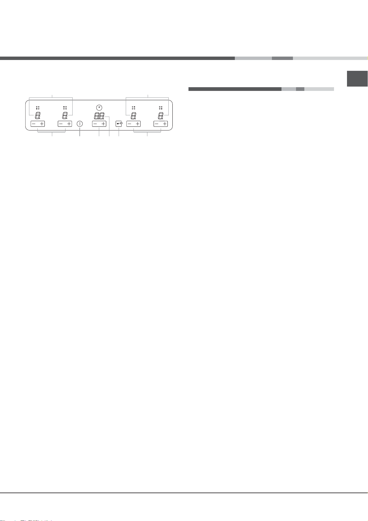
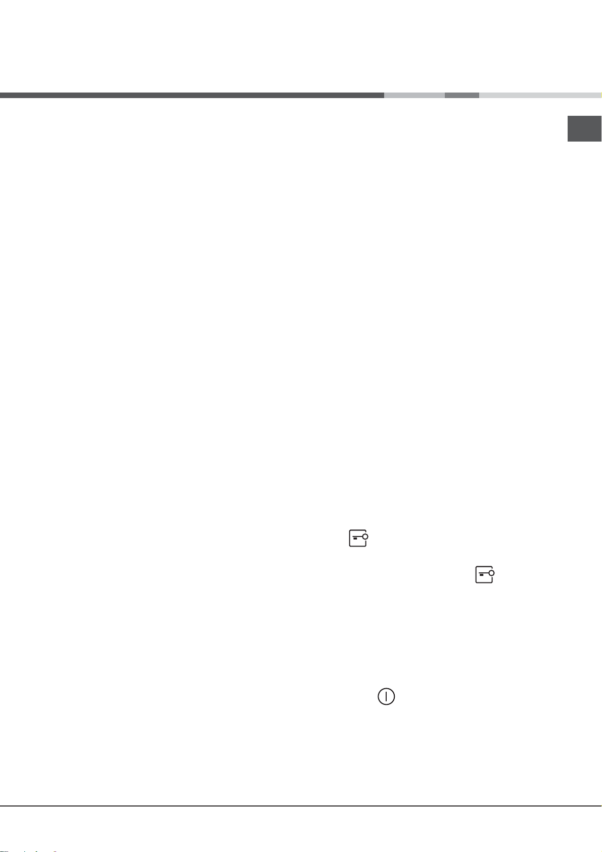
The control panel described in this manual is only a representative
example: it may not exactly match the panelon your appliance.
When using the touch control pannel panel:
•
Do not use gloves
•
Use a clean finger
•
Touch the glass smoothly
1 INCREASE(+)/REDUCE(-) POWER button - controls
the power level on every individual cooking zone
2 INCREASE (+)/ REDUCE(-) TIME button -controls the
time of cooking on the cooking zones.
3 COOKING ZONE POWER displays -show the power
level selected for every individual cooking zone
4 ON/OFF button switches the appliance on and off.
5 CONTROL PANEL LOCK button prevents accidental
changes to the hob settings and shows the control
panel has been locked
6. .TIMER display -shows the cookig time selected .
! For detailed information on the control panel functions
refer to “Start-up and use” section.
2 54
6
3
! Before operating your new appliance please read
this instruction booklet carefully. It contains important
information concerning the safe operation, installation
and maintenance of the appliance.
! Please keep these operating instructions for future
reference. Pass them on to any new owners of the
appliance.
Positioning
! Keep all packaging material out of the reach of children.
It may present a choking or suffocation hazard (see
Precautions and tips).
! The appliance must be installed by a qualified
professional in accordance with the instructions provided.
Incorrect installation may cause harm to people and
animals or may damage property.
Built-in appliance
Use a suitable cabinet to ensure that the appliance
functions properly.
• The supporting surface must be heat-resistant up to a
temperature of approximately 100°C.
• If the appliance is to be installed above an oven,
the oven must be equipped with a forced ventilation
cooling system.
• Avoid installing the hob above a dishwasher:
if this cannot be avoided, place a waterproof
separation device between the two appliances.
! This product complies with the requirements of the
latest European Directive on the limitation of power
consumption of the standby mode.
If no operations are carried out for a period of 2
minutes, after the residual heat indicator lights turn
off and the fan stops (if present), the appliance
automatically switches to the .off mode..
The appliance resumes the operating mode once the
ON/OFF button is pressed.
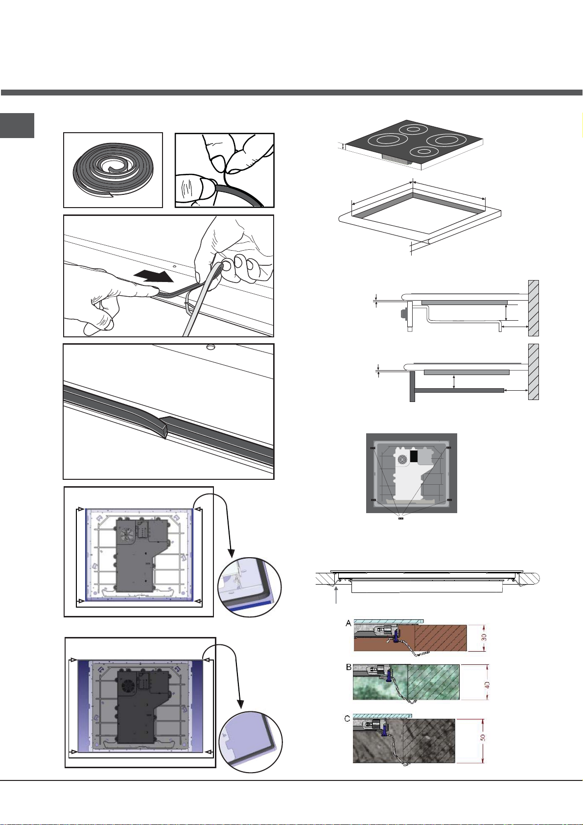
Ventilation
To allow adequate ventilation and to avoid overheating of the
surrounding surfaces the hob should be positioned as follows:
• At a minimum distance of 40 mm from the back panel
or any other vertical surfaces.
• So that a minimum distance of 20 mm is maintained
between the installation cavity and the cabinet
underneath.
• Kitchen cabinets adjacent to the appliance and taller
than the top of the hob must be at least 450 mm from
the edge of the hob.
Fixing
The appliance must be installed on a perfectly level
supporting surface. Any deformities caused by improper
fixing could affect the features and operation of the hob.
The thickness of the supporting surface
into account when choosing
the fixing hooks:
• 3,5 mm thick: 9,5 mm screws
the length of the screws for
should be taken
3
GB
1
2
4
3
5a- (models: 590 x 510 mm)
5b- (models: 690 x 510 mm)
Installation of the safety washer
CABINET DIMENSIONS
60
490
Min. 30/Max.50
SAFETY DISTANCES WITH FURNITURE
Min 5mm
Min 5mm
560
Min 20mm
Min 20mm
30mm
30mm
4
Fix the hob as follows:
1. Use short flat-bottomed screws to fix the 4 alignment
springs in the holes provided at the central point of each
side of the hob.
2. Place the hob in the cavity, make sure it is in a central
position and push down on the whole perimeter until the
hob is stuck to the supporting surface.
!
The screws for the alignment springs must remain
accessible.
!
In order to adhere to safety standards, the appliance
must not come into contact with electrical parts once it
has been installed.
!
All parts which ensure the safe operation of the
appliance must not be removable without the aid of a tool.
Electrical connection
The electrical connection for the hob and for any built-
!
in oven must be carried out separately, both for safety
purposes and to make extracting the oven easier.
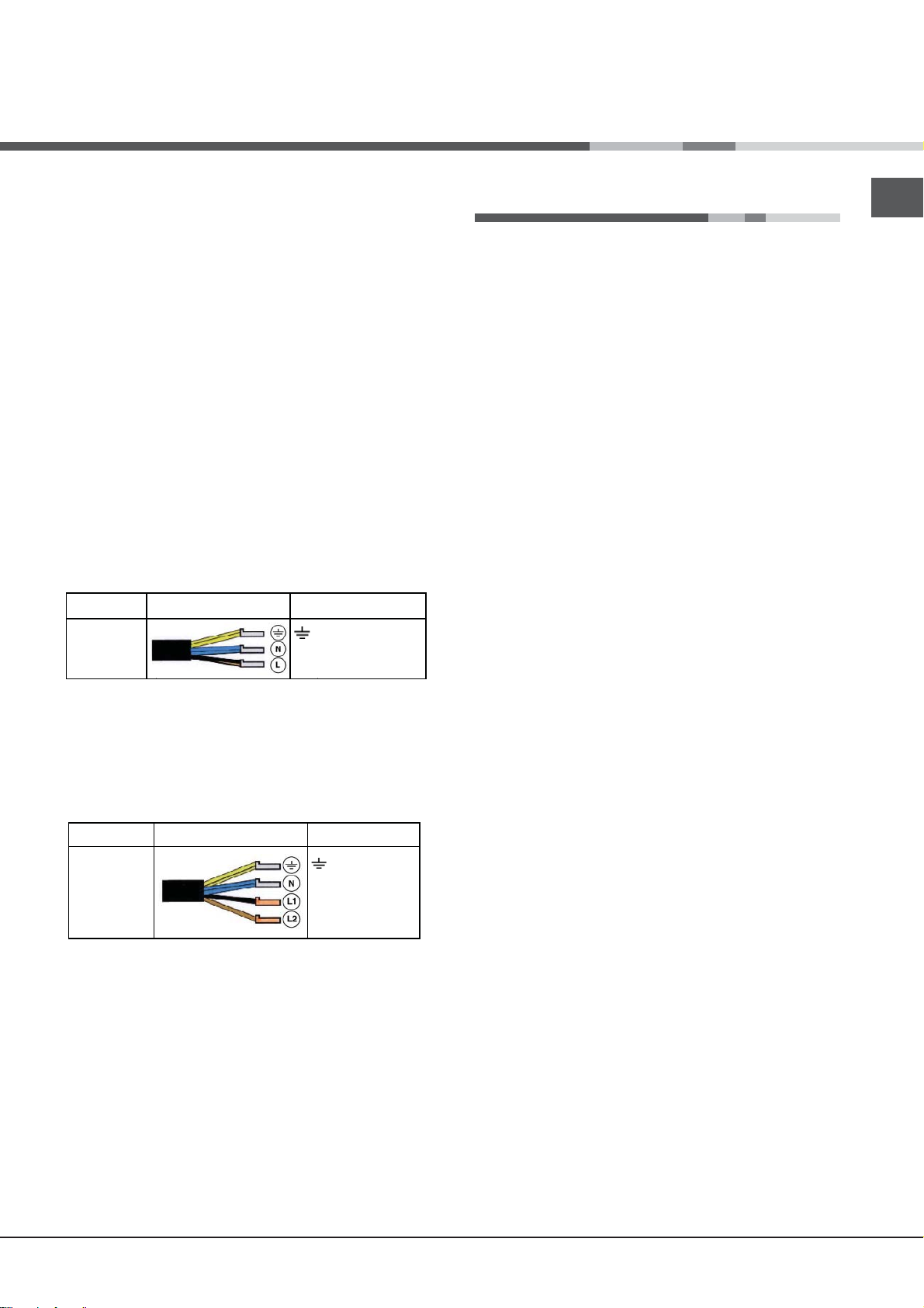
Single-phase connection
Voltage and
mains frequency
220-240V 1+N ~
50/60 Hz
The hob is equipped with a pre-connected electricity supply
cable, which is designed for single-phase connection.
Connect the wires in accordance with the instructions given
in the following table and diagrams:
Other types of connection
Voltage and
mains frequency
400V - 2+N ~
50/60 Hz
220-240V 3 ~
50/60 Hz
If the mains supply corresponds with one of the following:
Voltage and mains frequency
• 400V - 2+N ~ 50/60 Hz
• 220-240V 3 ~ 50/60 Hz
Separate the wires and connect them in accordance with
the instructions given in the following table and diagrams:
Connecting the electricity supply cable to the mains
If the appliance is being connected directly to the electricity
mains an omnipolar switch must be installed with a minimum
opening of 3 mm between contacts.
!
The installer must ensure that the correct electrical
connection has been made and that it is fully compliant
with safety regulations.
Electrical cable Wire connection
: yellow/green
: the two blue wires together
N
L
: brown and black together
Electrical cable Wire connection
: yellow/green;
N: the two blue wires
together
L1: black
L2: brown
Start-up and use
• The socket can withstand the maximum power of the
appliance, which is indicated on the data plate located
on the appliance itself.
• The voltage falls within the range of values indicated on
the data plate.
• The socket is compatible with the plug of the appliance. If
the socket is incompatible with the plug, ask an authorised
technician to replace it. Do not use extension cords or
multiple sockets.
!
Once the appliance has been installed, the power supply
cable and the electrical socket must be easily accessible.
The cable must not be bent or compressed.
!
The cable must be checked regularly and replaced by
!
authorised technicians only.
! The manufacturer declines any liability should these
safety measures not be observed.
! Do not remove or replace the power supply cable for any
reason. Its removal or replacement will void the warranty
and the CE marking. INDESIT does not assume liability for
accidents or damage arising from replacement/removal
of the original power supply cable. Replacement can only
be accepted when carried out by personnel authorised
by INDESIT and using an original spare part.
The glue applied on the gaskets leaves traces of grease
!
on the glass. Before using the appliance, we recommend
you remove these with a special non-abrasive cleaning
product. During the first few hours of use there may be a
smell of rubber which will disappear very quickly.
!
A few seconds after the hob is connected to the electricity
supply, a buzzer will sound. The hob may now be switched
on.
Types of noise during normal hob operation:
• Buzz: due to the vibration of the metallic parts that
make up the induction element and the pot; it is
generated by the electromagnetic field required for
heating and increases as the power of the induction
element increases.
• Soft whistle: heard when the pot placed on the heating
zone is empty; the noise disappears once food or water
is placed into the pot.
• Crackle: produced by the vibration of materials on the
bottom of the pot due to the flow of parasitic currents
caused by electromagnetic fields (induction); can be
more or less intense depending on the material making
up the bottom of the pot, and decreases as the pot
dimensions increase.
• Loud whistle: heard when two induction elements of
the same group function simultaneously at maximum
power and/or when the booster function is set on the
larger element while the other is auto-adjusted. Noise
is reduced by decreasing the power level of the autoadjusted induction element; pot bottom layers made of
different kinds of materials are among the main causes
of this noise.
GB
5
GB
• Fan noise: a fan is necessary to ensure the hob functions
correctly and to safeguard the electronic unit from possible
overheating. The fan functions at maximum power when
the large induction element is at maximum power or when
the booster function is on; in all other cases, it works at
average power depending on the temperature detected.
Furthermore, the fan may continue to work even after
switching the hob off, if the temperature detected is high.
The types of noise listed above are due to induction
technology and are not necessarily operational faults.
! If the (-)or (+)button is pressed for an extended period of
time, the display scrolls quickly though the power levels
and timer minutes.
Initial Light Conditions
When power is initially applied to the Cooktop, the touch control conducts a calibration process for the touch
keys, which requires a low level of ambient light in the
area of the touch keys.
If during this calibration process excessive ambient lighting is detected the User Interface displays „FL” (Infrared Ambient Light Error) and the control calibration process is suspended. In order to rectify the process any
lighting that could effect the calibration process should
be switched off (e.g. halogen cooker hood lighting). The
error will disappear when satisfactory ambient lighting
is detected and the touch control calibration procedure
will now complete satisfactorily.
The cooktop is switched On when a beep sound is
emitted and the cooking zones display shows the „0”
When the cooktop is off, after 5 sec. without any error/
alarm or residual heat to display, the control switches
off the (KEYLOCK LED)
consumption. As soon as we touch a key, the (KEYLOCK
LED
usual.
Switching off the cooktop is signalled by 3 beep sound.
. goes on and we can continue to operate as
. in order to reduce power
Setting the Power Management
The Cooktop maximum power limit (2800W) can be reduced by the user to 2200W, 1600W or 1000W
! Power limit selection is possible only during the first 30
seconds after connection of the appliance to the mains,
with the childlock function unlocked, and with all the cookig zones switched off.
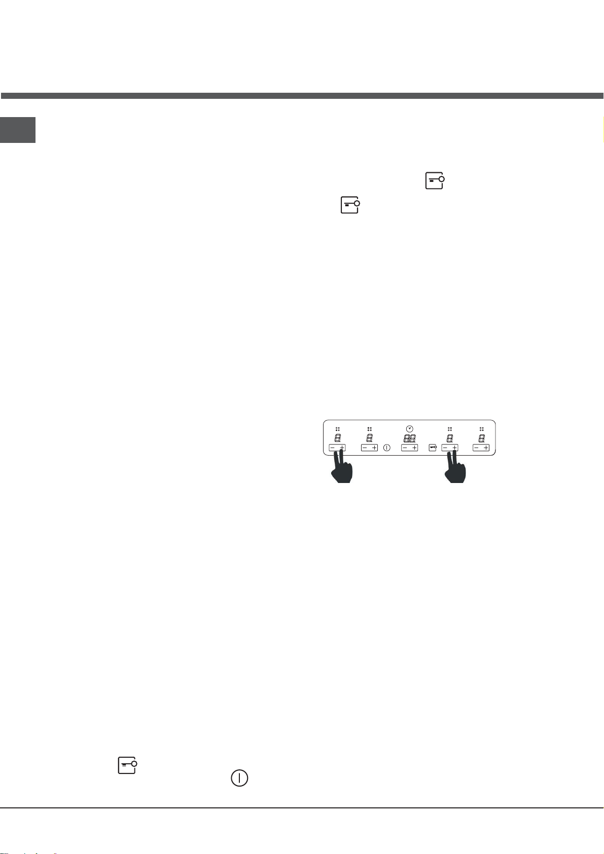
The sequence to set a new Cooktop Power Limit is:
1. Press and hold simultaneously the (+) and (-)
buttons corresponding to the front-left and the back-right cooking zones:
-The „FL” error can only be generated within approx 3s
of initial power being applied to the cooktop.
-We recommend that the user switches off all cooker
hood lighting and lighting directed towards the cooktop
when power is initially applied to the cooktop.
-After the touch control has conducted its initial calibra-
tion process, (approx 3s) any cooker hood or other lighting can be switched on as normal and will not affect the
operation of the touch control.
Switching on the hob
When power is initially applied to the Cooktop, the
touch control conducts a calibration process for the
touch keys, which requires a low level of ambient light in the area of the touch keys. If excessive ambient
lighting is detected, the User Interface displays „FL”
error and the calibration is suspended. The error will
disappear when satisfactory ambient lighting is detected and the touch control calibration procedure
will now complete satisfactorily
After connecting the hob to the electrical grid, the
touch pannel might be automatically locked. To unclock the pannel press and hold the Control Panel
Loock button .
To switch the hob on, press and hold the button for
approximately one second.
2. Select the desired power level by pressing any of the
(+) and (-) buttons, (excluding those of the timer)
3. Save the selected power level by pressing simultaneously the (+) and (-) buttons corresponding to the aforementioned cooking zones.
·Once this is done, new Cooktop Power Limit is recorded and there is a system reset.
·If during 60 seconds there is no action, changes are not
recorded and there is a system reset.
Switching on the cooking zones
Each cooking zone is switched on and controlled using the
(-) and (+) POWER buttons, which at the same time
are used for power adjustment.
• To begin operating a cooking zone, set the desired
power level (between 0 and 9) using the (-) and (+)
POWER buttons
Press and hold the (-) POWER button to set the power
level immediately at “9”
Press and hold (+) and (-) POWER buttons simulta
neously to return to power level “0”
If the power level is “0” press and hold the (+) button
to increase the power level quickly.
6
Fast Boil- “Booster” function
The booster function for some of the cooking zones may be
used to shorten heating-up times.
It may be activated by pressing the (+) POWER button over
level 9. This function boosts the power to 1600 W or 2000
W, depending on the size of the relevant cooking zone.
The activation of of the booster is signalled by a beep
sound, and the letter ‘P’ appearing on the display
corresponding to the selected cooking zone
The booster works for max 10 minutes. After these 10
minutes a beep sounds and the cooking zone will
return to level “9”
Starting Timer countdown.
The countdown starts 10 seconds after the last operation over the INCREASE (+)/ REDUCE(-) TIME but-
. If any power is selected, a beep sounds and
tons
the timer display stops blinking. The same happens
to the led heater.
The last minute will be displayed in seconds.
! When the timer is in countdown the user can
change the time at any time by touching the INCRE-
ASE / REDUCE TIME buttons
. Then the countdown
stops and the timer changes to time selection status
waiting a time selection.
GB
With the heater at Booster level, if the [+] key is
Touched an error beep sounds and the cookset
doesn’t change. With the heater at Booster level, if the
[-] key is Touched a beep sounds and the cookset is
reduced to 9.
Switching off the cooking zones
To switch off a cooking zone touch(-)and (+)
POWER selection buttons simultaneously.
A beep sounds and the corresponding display shows
“0”.
Using the Timer
! All the cooking zones can be programmed for a cooking
time duration between 1 and 99 min.
1.Activate the timer by pressing the INCREASE / REDUCE
TIME buttons. A beep sounds, the timer display shows a
“00” and the cooking zone displays show a “t” blinking
indicating that a cooking zone has to be selected.
2 Select the desired cooking zone by pressing any of
the cooking zones (+) or (-)keys. A beep sounds, the
LED next to the cooking zone display starts blinking if
no power is selected, or is on if any power is selected.
The timer display starts blinking indicating that the time
has to be selected
3. Set the desired cooking time by pressing again the
INCREASE / REDUCE TIME buttons.
! The user can select only one heater at a time.
!Pressing and holding the (+) and (-) keys increases
the speed of time selection.
! If the time is not selected before 10 seconds, the
timer is switched off.
! If the selected time is “00” after 10 seconds the timer
is switched off.
End of Timer countdown.
When the time set on the timer has elapsed the timed
heater is switched off, the timer display and the timed
heater led starts blinking and a timer alarm beep sounds
for one minute. The timer alarm can be cancelled by the
user at any time, even during the first minute of the alarm
. When the timer is in alarm status, by pressing any key
of the touch control the timer is switched off.
! To cancel the operation of the timer, select the time
value of “00”pressing the(+) and(-) TIME buttons at the
same time.
! When all the cooking zones are not powered, and one
of them is temporized at zero power level, the key-lock
function is activated after 1 minute.
Control panel lock
When the hob is switched on, it is possible to lock the oven
controls in order to avoid accidental changes being made to
the settings (by children, during cleaning, etc.).
Press the
will illuminate and an audible beep sound will be emmited.
To use any of the controls (e.g. to stop cooking), you
must switch off this function. Press the
few moments, the icon will stop illuminating and the lock
function will be removed.
All the keys on the cooking zone selection wil be locked
if :the cooktop is off,,
if the Control Panel Lock is activated or
if an error on a cooktop occurs..
. button to lock the control panel: -the icon
.button for a
Switching off the hob
Press the button to switch off the appliance - do not
rely solely on the pan sensor.
If the control panel lock has been activated, the controls
will continue to be locked even after the hob is switched
on again. In order to switch the hob on again, you must
first remove the lock function.
7
GB
*
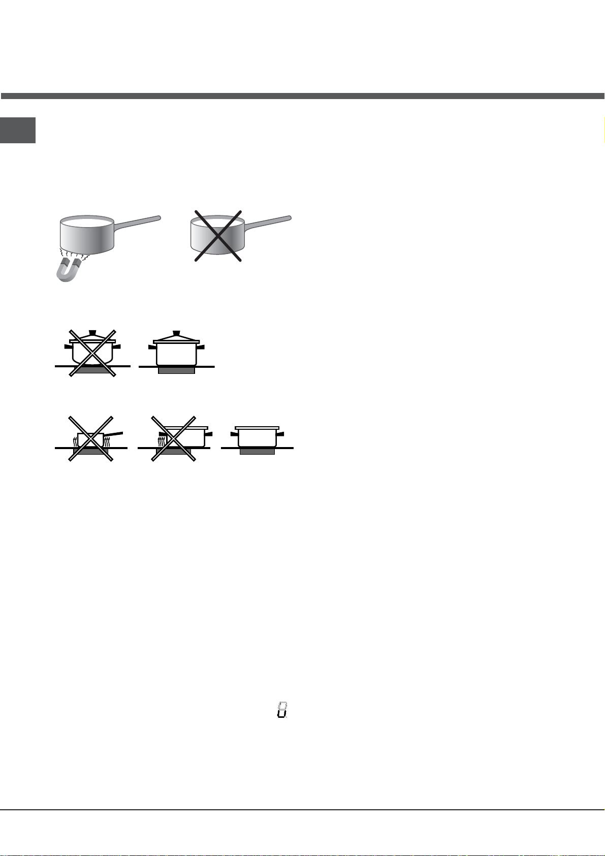
SUITABLE
UNSUITABLE
Cast iron
Enamelled steel
Special stainless steel
Copper,
Aluminium, Glass, Earthenware,
Ceramic, non magnetic Stainless steel
Practical advice on using the appliance
! Use cookware made from materials which are
compatible with the induction principle (ferromagnetic
material). We especially recommend pans made from:
cast iron, coated steel or special stainless steel adapted
for induction. Use a magnet to test the compatibility of
the cookware.
After 10 sec. with no pan on the heating zone, a warning
beep signal is emmited.
After 60 sec. with no pan on the heating zone,, the heater
switches off.
Overheating protection
If the electronic elements overheat, the number signalizing
the power level starts flashing, and the letter “c” appears
on the display. When the temperature has reached a
suitable level, this message disappears and the hob may
be used again.
Safety switch
In addition, to obtain the best results from your hob:
• Use pans with a thick, flat base in order to fully utilise the
cooking zone.
• Always use pans with a diameter which is large enough
to cover the hotplate fully, in order to use all the available
heat.
• Make sure that the base of the cookware is always clean
and dry, in order to fully utilise and extend the life of both
the cooking zones and the cookware.
• Avoid using the same cookware which has been used
on gas burners: the heat concentration on gas burners
may distort the base of the pan, causing it not to adhere
correctly.
Safety devices
Pan sensor
Each cooking zone is equipped with a pan sensor device.
The hotplate only emits heat when a pan with suitable
measurements for the cooking zone is placed on it.
The appliance has a safety switch which automatically
switches the cooking zones off after they have been in
operation for a certain amount of time at a particular power
level. When the safety switch has been triggered, the display
shows “0”.
For example: the right rear hotplate is set to 5 and will
switch off after 5 hours of continuous operation, while the
front left hotplate is set to 2 and will switch off after 8 hours.
When one or more keys are activated for more than
10 sec. the touch control. switches off
A warning beep sounds is emitted every 10
sec., while the key/s is/are activated.
With all heaters at zero power during 10 sec. the
Cooktop is switched off.
If the switching off is due to an accidental activa-
tion of keys, the touch control actuates as above.
Buzzer
This can also indicate several irregularities:
• An object (a pan, cutlery, etc.) has been placed on the
control panel for more than 10 seconds.
• Something has been spilt on the control panel.
• A button has been pressed for too long. All of the above
situations may cause the buzzer to sound. Remove the
cause of the malfunction to stop the buzzer. If the cause of
the problem is not removed, the buzzer will keep sounding
and the hob will switch off.
Errors and Alarms
The “u” sign on the display appears if after selecting the
cooking zone the pan is not placed on a heater , or in
case of:
• An incompatible pan
• A pan whose diameter is too small
• The pan has been removed from the hotplate.
8
When an error is detected, the whole appliance or the
heater/s are switched off, a beep sounds (only if one or
more heaters are active) and all displays show a ‘F’
letter and the error code (an index number or a letter)
alternately.
If the problem does not disappear by itself, please
contact the Technical Service.
 Loading...