

Page 1
Cooker Hood
HE63
HE73
HE93
Instruction on mounting and use
Page 2
! It is important to conserve this booklet for
consultation at any moment. In the case of sale,
cession or move, make sure it is together with the
product.
! Read the instructions carefully: there is important
information about installation, use and safety.
! Do not carry out electrical or mechanical variations
on the product or on the discharge conduits.
Installation
Electric connection
! The power tension must correspond with the tension
shown on the characteristics label situated inside the
hood. If provided with a plug, attach the hood to a
socket conforming to the regulations in force and
placed in an accessible zone. If without a plug,
(
connected directly to the power supply
regulation bipolar switch with a distance of the
contacts on opening not less than 3mm (
! If necessary, the situating of the supply cable must
be carried out by the technical assistance service or a
qualified person.
! An authorized installer must carry out the electrical
connection of the hood.
! The company declines any responsibility whenever
these regulations are not respected.
), use a
accessible
).
2
Page 3
The minimum distance between the supporting surface
for the cooking vessels on the hob and the lowest part
of the range hood must be not less than 50cm from
electric cookers and 70cm from gas or mixed cookers.
If the instructions for installation for the gas hob specify
a greater distance, this must be adhered to.
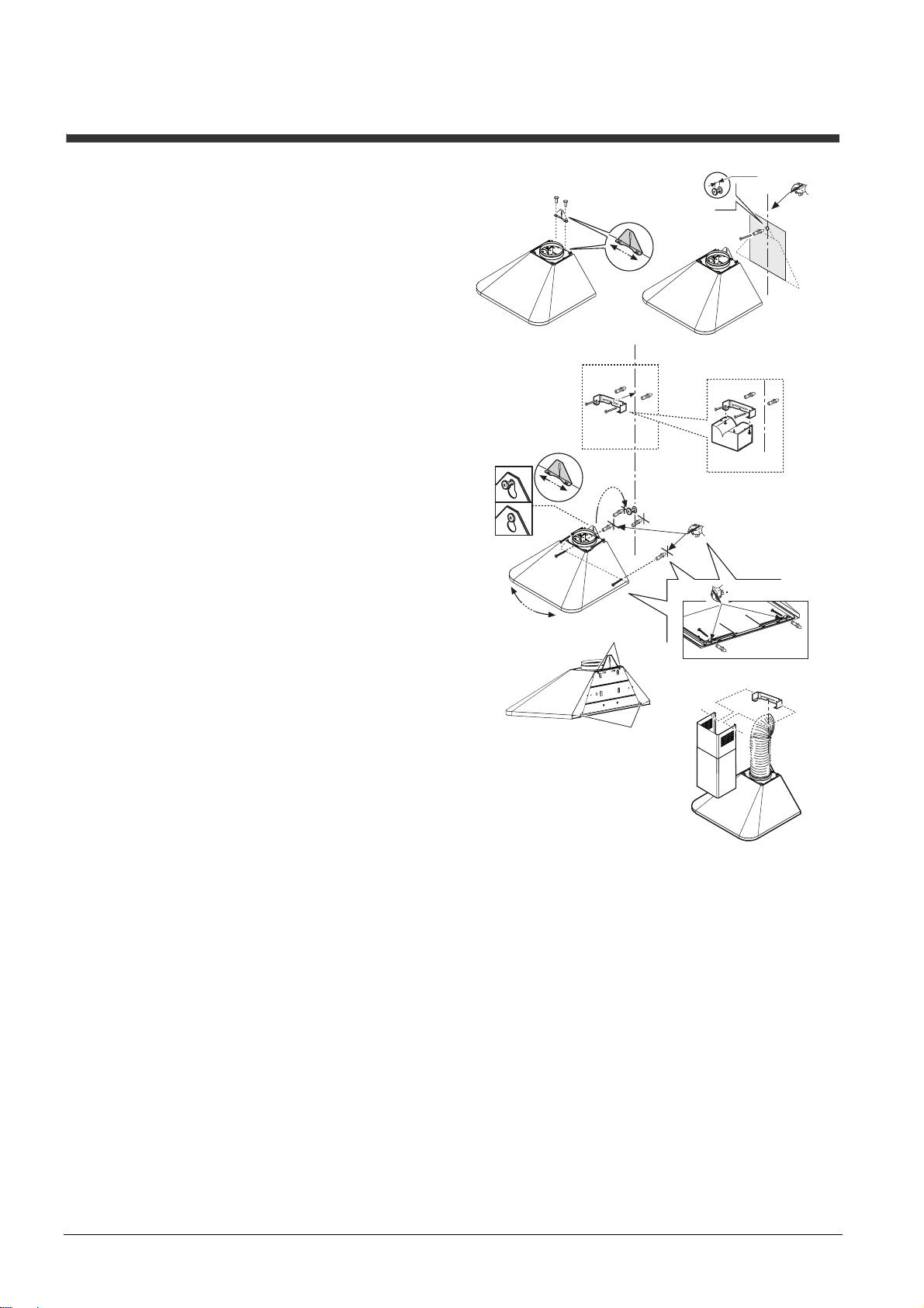
Fix the bracket behind the hood near the joining ring
(Fig. 4.1a).
Note: The bracket can be adjusted horizontally. This is
useful for successive small adjustments of the position
of the hood (Fig. 4.1b).
Draw a centerline on the wall from the cooking top to
the ceiling (Fig. 5.2).
Taking account of the distance from the cooking top,
mark the distance from the cooking top and position
the template (if supplied) to the wall on the mark (Fig.
5.3).
Mark the hole to be made, make it and insert the dowel
and partially screw 1 screw up (Fig. 5.4).
Fix the flue support to the wall as close as possible to
the ceiling (Fig. 6.1). In this phase, for the filter version,
also fix the baffle (Fig. 6.2).
Connect the hood to the partially screwed screw (Fig.
6.3a – if necessary the hood can be adjusted
horizontally, repositioning the bracket suitably – Fig-
6.3b)
Mark the 4 definitive fixing points of the hood:
2 below: removing the fat filters (Fig. 6.4), 2 above at
the sides of the bracket.
Remove the hood, make the holes, insert the dowels
(Fig. 6.5), replace the hood, insert and screw all the
screws up decisively (Fig.6.6 - Fig. 6.7).
Suction Version: the steam is sucked and sent outside
through a discharge tube that is fixed to the joining ring
positioned on the upper part of the hood.
Attention! If the hood is provided with a mounted
carbon filter, this must be removed.
The discharge air must not be discharged in a conduit
used for expelling fumes produced by gas or other fuel
apparatuses but must have an independent exit. All the
national regulations about the discharge of air must be
respected.
Filter Version: the filtered air passing through a carbon
filter is recycled into the surrounding environment.
Attention! If the hood is not provided with a carbon
filter it must be ordered and mounted before use.
Installing the telescopic flue.
Connect the hood to the power supply and fix the
telescopic flue to the support with two screws and let
the lower part slide until reaching the appropriate seat
on the upper side of the hood (Fig. 7).
2 x Ø 3,5x9,5
1a.
1b.
Fig. 4 Fig. 5
1.
2 x Ø 8mm
2 x 5x45
3a.
3b.
7.
6.
3.
4.-5.-6.
Fig. 6
4 x Ø 8mm
4 x 5x45
4.-5.-6.
÷ 5 mm
2.
1 x Ø 8mm
1 x 5x45
5.
2 x Ø 3x9
Fig. 7
4.
6.
4.
3.
2.
2 x Ø 3,5x6,5
4.
6.
5.
5.
3
Page 4

Control panel
Press
Press
To increase or diminish the suction speed, press keys
1,2 or 3.
Press O to interrupt the suction function.
to enable all the functions (ON/OFF key).
to turn the lights on and off.
4
Page 5

! We advise switching the hood on, at minimum power,
before beginning to cook to favour the optimal
expulsion of odours. In addition we advise turning it off
every time 10/15 minutes after finishing cooking.
! We advise frying under the hood only under constant
supervision.
! It is forbidden to cook flambé under the hood
because there is the risk of causing a fire.
The best performance of the apparatus is obtained
with external expulsion: we advise using the hood in
this version if possible.
External exhausting version
In this case the fumes are
conveyed outside by means of a
special pipe connected with the
connection ring located on top of
the hood Diameter of the
exhausting pipe must be equal to
that of the connection ring =
150mm.
In the horizontal runs the exhausting pipe must be
slightly slanted (about 10°) and directed upwards to
vent the air easily from the room to the outside.
Attention! If the hood is supplied with active charcoal
filter, then it must be removed.
Filtering version
One active charcoal filter is needed for this and can be
obtained from your usual retailer.
The filter removes the grease and smells from the
extracted air before sending it back into the room
through the upper outlet grid.
5
Page 6
! It is always necessary to isolate the hood from the
power supply during cleaning and maintenance.
Therefore remove the plug.
We recommend carrying our maintenance regularly
(about every 10 days) to ensure efficacious and
constant performance of the hood.
Cleaning the hood
The hood should be cleaned frequently, both internally
and externally. Use a cloth damped in neutral
detergent liquids.
Avoid the use of products containing abrasives.
Attention: failure to observe the cleaning regulations of
the hood and the substitution and cleaning of the filters
leads to the risk of fire. We therefore recommend
keeping to the suggested instructions.
Cleaning the grease filters
The fats filter serves to capture the particles of fat in
suspension that come from the cooking.
It must be cleaned once a month with non-aggressive
detergents manually or in a dishwasher at low
temperature and short cycle.
If washed in a dishwasher it can become opaque over
time but its filtering ability is not lessened in any way.
Dismantle it using the corresponding handles, pushing
them backward first and then pulling them down.
After having washed it, dry it carefully and assemble it
again in its seat, reversing the procedure.
Clean the perimeter suction panel (when envisaged)
with the same frequency as the anti-fat filter. Use a
cloth and a not too concentrated liquid detergent.
Never use abrasive substances.
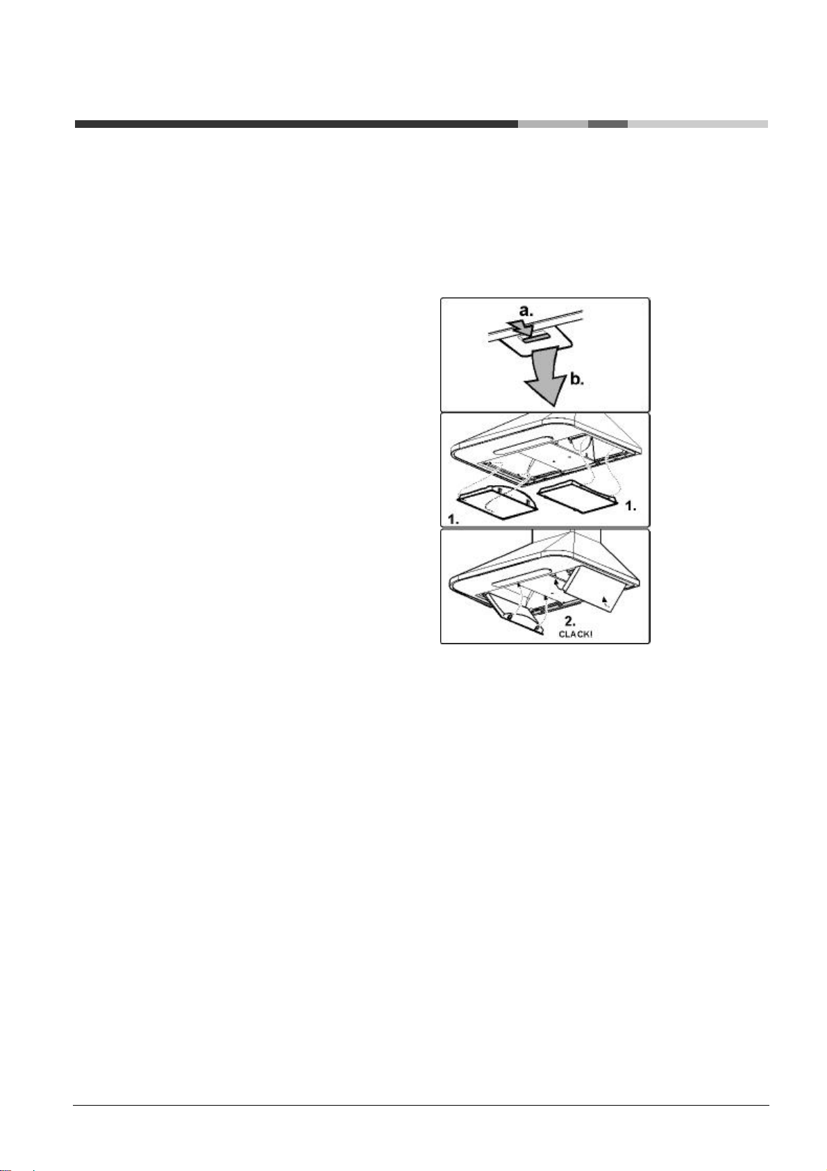
Mounting and changing the filter
The carbon filter must be changed every 6 months.
1-Remove the fats filter (a.b)
2-Mount the filters as illustrated in the figures below.
3-To dismantle, proceed inversely.
4-Put the anti-fat filters back.
Replacing lamps
Remove the plug!
Bulb/s:
Remove the overhead light and remove the bulb to
change. Only use 40W lamps.
Make sure the bulbs are cold before touching them.
Halogen bulbs:
Use a small screwdriver or other tool suitable for
prising.
Substitute the halogen bulb with another of equal
value. Close with the trigger fixing.
6
Page 7

General safety
! The hood has been designed and constructed in
conformity with international safety regulations. These
warnings are provided for safety reasons and must be
carefully read.
• This apparatus has been designed for use by adults.
• Children and invalids are not allowed to use this
apparatus without supervision. Check that children do
not play with the apparatus.
• The premises must have sufficient ventilation when
the hood is being used at the same time as other
apparatuses that use gas and other fuels. If the hood
must be installed in a kitchen where there is a waterheater or a gas heating system we recommend, for
safety reasons, not using the suction version. It is
therefore necessary to equip the apparatus with an
active carbon filter, in this way allowing recycling use.
• For safe performance, low pressure should not
exceed 0.04 mbar: in this way re-suction of the
expulsion gas will be avoided. This can be obtained
ensuring entry of air into the room through openings
that cannot be closed.
• The sucked air must not be conveyed in a conduit
used for the discharge of fumes from apparatuses
supplied with energy other than electricity.
• It is severely forbidden to cook food on the flame
under the hood.
• The use of naked flame damages the filters and can
cause fires. It must therefore be avoided in any case.
• Frying must be carried out under control to avoid the
overheated oil catching fire.
• As far as the technical and safety measures to adopt
for the discharge of fumes are concerned, keep strictly
to what is envisaged by the regulations of the
competent authorities.
• For any problem regarding the expulsion of fumes,
keep to the instructions of the competent authority.
The company declines any responsibility in the case of
damage or fire caused by apparatus resulting from
failure to observe the above-mentioned instructions.
• Disused domestic appliances can be delivered to
the public collecting service, taken to suitable local
authority areas or, if envisaged by national laws on the
matter, resold to dealers at the same time as
purchasing new, equivalent, types of product.
• All the main producers of domestic appliances are
active in the creation and management of collecting
systems of disused apparatuses.
! In case of anomalies apply to the authorized technical
assistance service and require original spare parts.
! The information and technical data are subject to
change and the producer, in line with technical
progress, maintains the right to make modifications
that he considers necessary without prior notice.
This appliance is marked according to the European
directive 2002/96/EC on Waste Electrical and
Electronic Equipment (WEEE). By ensuring this product
is disposed of correctly, you will help prevent potential
negative consequences for the environment and
human health, which could otherwise be caused by
inappropriate waste handling of this product.
The symbol
accompanying the product, indicates that this
appliance may not be treated as household waste.
Instead it shall be handed over to the applicable
collection point for the recycling of electrical and
electronic equipment. Disposal must be carried out in
accordance with local environmental regulations for
waste disposal.
For more detailed information about treatment,
recovery and recycling of this product, please contact
your local city office, your household waste disposal
service or the shop where you purchased the product.
on the product, or on the documents
Disposal
• Disposing of the packaging material: keep to the
local regulations so that the packaging can be re-used.
• European directive 2002/96/CE on electric and
electronic apparatus waste provides that domestic
appliance should not be disposed of in the normal flow
of solid urban waste. The disused apparatuses must
be collected separately to make the rate of recovering
and recycling of the materials they consist of and
prevent potential damage to health and the
environment. The symbol of the barred basket is shown
on all the products to remind users of the need for
separate collection.
7
Page 8

LI2S7A
 Loading...