

Page 1
Operating Instructions
OVEN
GB
English,1 Polski, 13
PL
HB 86 C.2
HB 86 C.2 IX
Contents
GB
Installation, 2-4
Positioning
Electrical connections
Data plate
Assistance
Description of the appliance, 5
Overall view
Control panel
Start-up and use, 6
Starting the oven
Cooking modes, 7-8
Cooking modes
Programming your cooking
Practical cooking advice
Cooking advice table
The electronic cooking programmer, 9
Hob, 10
Type of hob
Switching on the glass ceramic hob
Practical advice on using the glass ceramic hob
Precautions and tips, 11
General safety
Disposal
Respecting and conserving the environment
Maintenance and care, 12
Switching the appliance off
Cleaning the appliance
Cleaning the oven door
Replacing the light bulb
Page 2
560 mm.
45 mm.
Installation
GB
Before placing your new appliance into operation
please read these operating instructions carefully.
They contain important information for safe use, for
installation and for care of the appliance.
Please keep these operating instructions for future
reference. Pass them on to possible new owners of
the appliance.
Positioning
Keep packaging material out of the reach of
children.It can become a choking or suffocation
hazard (see Precautions and tips).
The appliance must be installed by a qualified
person in compliance with the instructions provided.
Incorrect installation may cause harm to persons,
animals or may damage property.
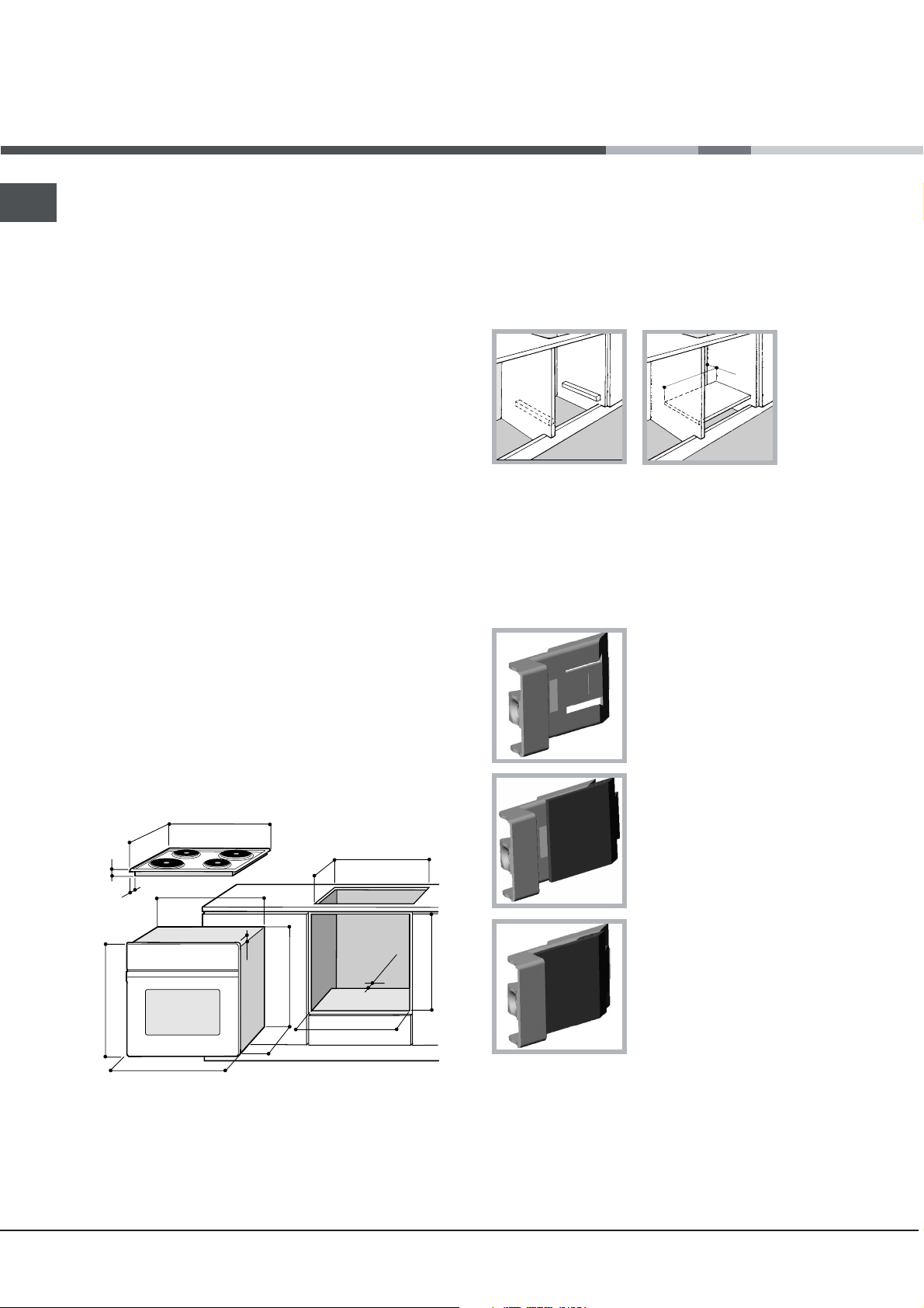
Fitting the appliance
Use the appropriate cabinet to ensure that the
appliance functions properly.
The panels adjacent to the oven must be made of
heat-resistant material.
Cabinets with a veneer exterior must be assembled
with glues which can withstand temperatures of up
to 100°C.
Ventilation
To ensure good ventilation, the back panel of the
cabinet must be removed. It is advisable to install the
oven so that it rests on two strips of wood, or on a
completely flat surface with an opening of at least 45 x
560 mm (see diagrams).
Centring and fastening
Position the 4 tabs on the side of the oven according
to the 4 holes of the outer frame. Adjust the tabs
according to the thickness of the cabinet side panel,
as shown below:
thickness of 20 mm: take off
the removable part of the tab
(see diagram)
To install the oven under the counter (see
diagram) and in a kitchen unit, the cabinet must
have the following dimensions:
555
580
560
min
+4 -0
min
45
+4 -0
480
23
572
558
543545
500
39
15
595
595
The appliance must not come into contact with
electrical parts once it has been installed.
The consumption indications on the data plate have
been calculated for this type of installation.
min
575-585
thickness of 18 mm: use the
first groove, which has already
been set in the factory (see
diagram)
thickness of 16 mm: use the
second groove (see diagram)
Secure the appliance to the cabinet by opening the
oven door and putting 4 screws into the 4 holes of the
outer frame.
All parts which ensure the safe operation of the
appliance must not be removable without the aid of a tool.
2
Page 3
Electrical connections
NL2L3
L1
P
The cooker must be connected to the mains
electricity supply. It is designed to operate with
alternating current at the voltage and frequency
indicated on the data plate (see the following page).
The hob is connected to the cooker using a special
connector.
BUILT-IN HOB
Only on
certain models
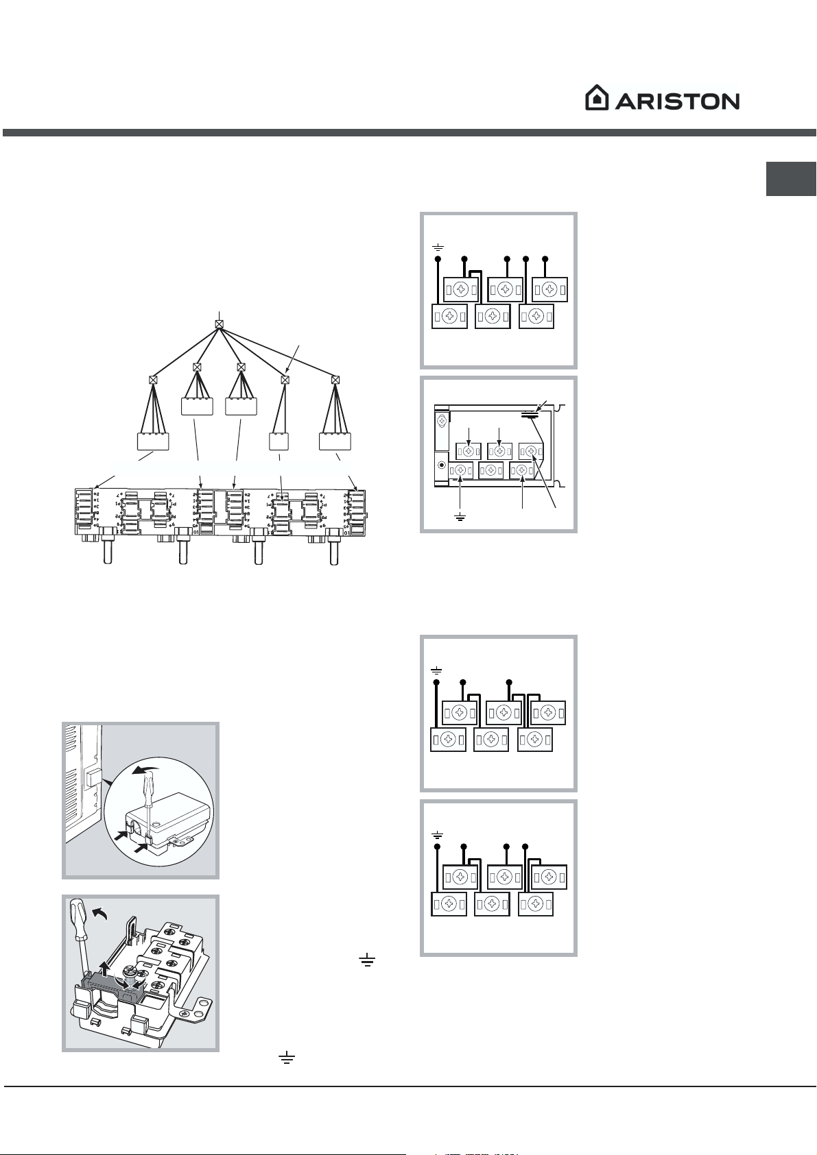
The terminal board is designed for a 400 V threephase connection (see diagrams below).
400V 3N~H05RR-F
5x2.5 CEI-UNEL 35363
NL3L1L2
5
3
4
1
2
GB
WHITE RED
BUILT-IN COOKER
YELLOW
BLUE GREEN
Replace the metal protection after performing all the
necessary hob connections. If the hob is removed
from its position, the red cap which was originally
protecting the red connector must be replaced.
Fitting the power supply cable
1. Open the terminal
board by inserting a
screwdriver into the
side tabs of the cover.
Use the screwdriver as
a lever by pushing it
down to open the cover
(see diagram).
2. Loosen the cable
clamp screw and
remove it, using a
screwdriver as a lever
(see figure).
3. Remove the wire
contact screws L-N, then fasten the wires
under the screw heads,
respecting the colour
code: Blue (N), Brown
(L) and Yellow-Green
Verde (
).
If the electrical system has other characteristics (see
diagrams below), carry out the electrical connection
using the connection supports provided in the box
P.
230V 1N~H07RN-F 3x4
NL
5
3
4
2
CEI-UNEL 35364
1
400V 2N~H05RR-F
NL2L1
5
3
4
2
4x2.5 CEI-UNEL 35363
1
3. Secure the power supply cable by fastening the
clamp screw.
4. Close the cover of the terminal board.
3
Page 4
GB
Connecting the supply cable to the mains
Install a standardised plug corresponding to the load
indicated on the data plate (see side).
The appliance must be directly connected to the
mains using an omnipolar circuit-breaker with a
minimum contact opening of 3 mm installed between
the appliance and the mains, suitable for the load
indicated and complying with current electrical
regulations (the earthing wire must not be interrupted
by the circuit-breaker). The supply cable must not
come into contact with surfaces with temperatures
higher than 50°C.
The installer must ensure that the correct electrical
connection has been made and that it is compliant
with safety regulations.
Before connecting to the power supply, make sure
that:
The appliance is earthed and the plug is compliant
with the law.
The socket can withstand the maximum power of
the appliance, which is indicated on the data plate
(see below).
The voltage must be in the range between the
values indicated on the data plate (see below).
The socket is compatible with the plug of the
appliance. If the socket is incompatible with the
plug, ask an authorised technician to replace it. Do
not use extension cords or multiple sockets.
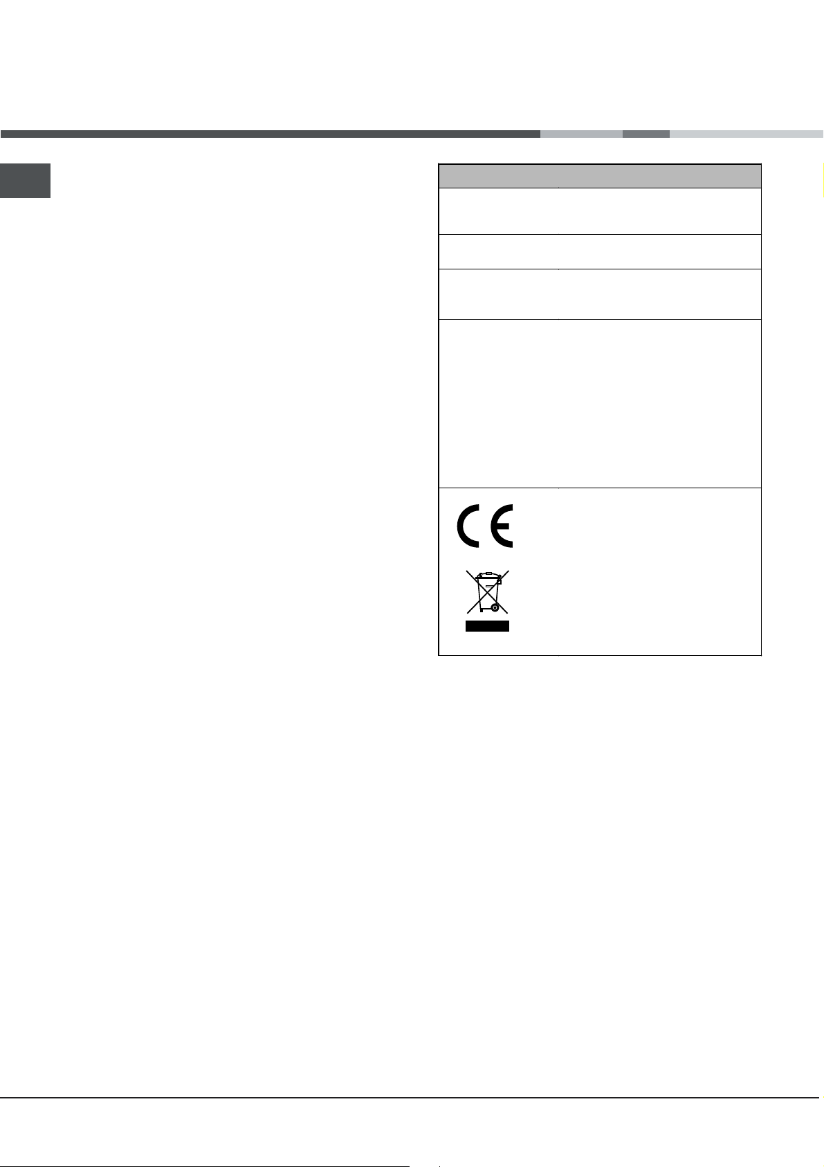
DATA PLATE
Dimensions
Volume
Electrical
connections
ENERGY LABEL
width 43.5 cm
height 32 cm
depth 40 cm
lt. 56
voltage: 230V/400V~ 3N 50Hz
maximum power absorbed 9200W
Directive 2002/40/EC on the label
of electric ovens.
Standard EN 50304
Energy consumption for Natural
a
convection – heating mode:
Convection mode.
Declared energy consumption for
Forced convection Class – heating
u
mode:
This appliance conforms to the
following European Economic
Community directives:
73/23/EEC of 19/02/73 (Low
Voltage) and subsequent
amendments;
- 89/336/EEC of 03/05/89
(Electromagnetic Compatibility) and
subsequent amendments;
- 93/68/EEC of 22/07/93 and
subsequent amendments.
- 2002/96/CE
Baking.
Once the appliance has been installed, the power
supply cable and the electrical socket must be easily
accessible.
The cable must not be bent or compressed.
The cable must be checked regularly and replaced
by authorised technicians only (see Assistance).
The manufacturer declines any liability should
these safety measures not be observed.
Assistance
Communicating:
appliance model (Mod.)
serial number (S/N)
This information is found on the data plate located on the appliance and/or on the packaging.
4
Page 5
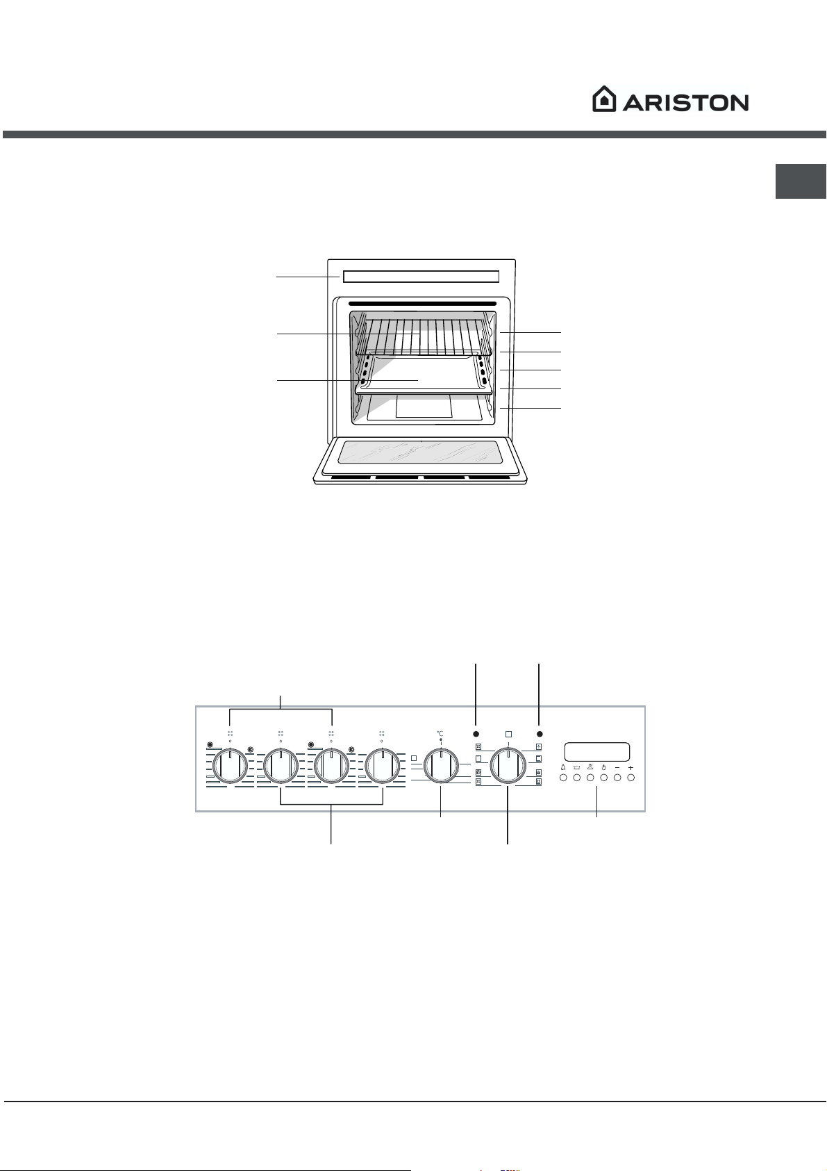
Description of the
appliance
Overall view
Control panel
GRILL rack
DRIPPING PAN
GB
GUIDES for the
sliding racks
position 5
position 4
position 3
position 2
position 1
Control panel
EXTENDABLE
HOTPLATES
12
11
10
9
8
7
2
3
4
5
6
12
11
10
9
8
7
Knob
1
12
2
11
3
10
4
9
5
8
7
6
2
3
4
5
6
HOTPLATES
Knob
12
11
10
9
8
7
HOTPLATES
indicator
light
1
2
MAX
3
220
4
180
5
6
60
100
140
THERMOSTAT
knob
THERMOSTAT
indicator
light
0
ELECTRONIC
PROGRAMMER
SELECTOR
Knob
5
Page 6
Start-up and use
GB
! The first time you use your appliance, heat the
empty oven with its door closed at its maximum
temperature for at least half an hour. Ensure that the
room is well ventilated before switching the oven off
and opening the oven door. The appliance may
produce a slightly unpleasant odour caused by the
burning away of protective substances used during
the manufacturing process.
Should the appliance be equipped with an
electronic programmer, to use the electric oven, just
press button
display) before selecting the desired cooking
function.
(the symbol will appear on the
Starting the oven
1. Select the desired cooking mode by turning the
SELECTOR knob.
2. Select the desired temperature with the
THERMOSTAT knob. See the Cooking advice table
for cooking modes and the suggested cooking
temperatures (see Cooking Modes).
3. When preheating is finished, the THERMOSTAT
indicator light will stay on: place the food in the
oven.
4. You may do the following during cooking:
- change the cooking mode by turning the
SELECTOR knob.
- change the temperature by turning the
THERMOSTAT knob.
- stop cooking by turning the SELECTOR knob to the
0 position.
Cooling ventilation
In order to cool down the external temperature of the
oven, some models are fitted with a cooling fan that
blows out air between the control panel and the oven
door.
! Once the cooking has been completed, the cooling
fan remains on until the oven has cooled down
sufficiently.
Oven light
It goes on when selecting
knob. It stays on when a cooking mode is selected.
with the SELECTOR
! Never put objects directly on the oven bottom to
avoid damaging the enamel coating.
! Always place cookware on the rack(s) provided.
6
Page 7
Cooking modes
Cooking modes
! A temperature value can be set for all cooking
modes between 60°C and Max, except for
BARBECUE (recommended: set only to MAX
power level);
GRATIN (recommended: do not exceed 200°C).
a TRADITIONAL OVEN mode
Both the top and bottom heating elements will come
on. With this traditional cooking mode, it is best to
use one cooking rack only: if more than one rack is
used, the heat will be distributed unevenly.
u BAKING mode
The rear heating element and the fan come on,
guaranteeing the distribution of heat delicately and
uniformly throughout the oven. This mode is ideal for
baking and cooking temperature sensitive foods
such as cakes that need to rise and to prepare
certain tartlets on 3 shelves simultaneously.
v FAST COOKING mode
The heating elements and the fan come on,
guaranteeing the distribution of heat consistently
and uniformly throughout the oven.
Pre-heating is not necessary for this cooking mode.
This mode is especially recommended for cooking
pre-packed food quickly (frozen or pre-cooked). The
best results are obtained if you use one cooking
rack only.
b MULTI-COOKING mode
All the heating elements (top, bottom and circular),
as well as the fan, will come on. Since the heat
remains constant throughout the oven, the air cooks
and browns food uniformly. A maximum of two racks
may be used at the same time.
d BARBECUE mode
The top heating element comes on.
The high and direct temperature of the grill is
recommended for food that requires high surface
temperature. Always cook in this mode with the oven
door closed.
e GRATIN mode
The top heating element, as well as the fan, will
come on. This combination of features increases the
effectiveness of the unidirectional thermal radiation
of the heating elements through forced circulation of
the air throughout the oven. This helps prevent food
from burning on the surface, allowing the heat to
penetrate right into the food. Always cook in this
mode with the oven door closed.
Practical cooking advice
! Do not place racks in position 1 and 5 during fan-
assisted cooking. Excessive direct heat can burn
temperature sensitive foods.
! In the BARBECUE and GRATIN cooking modes,
place the dripping pan in position 1 to collect
cooking residues (fat and/or grease).
MULTI-COOKING
Use position 2 and 4, placing the food that
requires more heat on 2.
Place the dripping pan on the bottom and the rack
on top.
BARBECUE
Insert the rack in position 3 or 4. Place the food in
the centre of the rack.
We recommend that you set the maximum power
level. The top heating element is regulated by a
thermostat and may not always be on.
PIZZA MODE
GB
w PIZZA mode
The bottom and circular heating elements, as well as
the fan, will come on. This combination heats the
oven rapidly by producing a considerable amount of
heat, particularly from the bottom element. If you
use more than one rack simultaneously, switch the
position of the dishes halfway through the cooking
process.
Use a light aluminium pizza pan. Place it on the
rack provided.
For a crispy crust, do not use the dripping pan
(prevents crust from forming by extending
cooking time).
If the pizza has a lot of toppings, we recommend
adding the mozzarella cheese on top of the pizza
halfway through the cooking process.
7
Page 8
GB
g
g
g
g
g
g
g
Cooking advice table
Setting made Type of food Weight
Traditional
Bakin
Fast cookin
Multi-cookin
Pizza
Barbecue
Gratin
N.B.: cooking times are approximate and may vary according to personal taste. When cooking using the grill or
gratin, the dripping pan must always be placed on the 1st oven rack from the bottom.
Duck
Roast veal or beef
Pork roast
Bi scuits (sh ort pastry)
Tarts
Tarts
Fruit cakes
Plum cake
Sponge cake
Stuffed pancakes (on 2 racks)
Small cakes (on 2 racks)
Cheese puffs (on 2 racks)
Cream puffs (on 3 racks)
Biscuits (on 3 racks) Meringues
(on 3 racks)
Frozen food
Pizza
Courgette and prawn pie
Country style spinach pie
Turnovers
Lasagne
Golden Rolls
Chicken morsels
Pre-cooked food
Golden chicken wings
Fresh Food
Bi scuits (sh ort pastry)
Plum cake
Cheese puffs
Pizza (on 2 racks)
Lasagne
Lamb
Roast chicken + potatoes
Mackerel
Plum cake
Cream puffs (on 2 racks)
Biscuits (on 2 racks)
Sponge cake (on 1 rack)
Sponge cake (on 2 racks)
Savoury pies
Pizza
Roast veal or beef
Chicken
Soles and cuttlefish
Squid and prawn kebabs
Cod filet
Grilled vegetables
Veal steak
Cutlets
Hamburgers
Mackerels
Toasted sandwiches
Grilled chicken
Cuttlefish
(in k
0.5
0.7
0.5
1.2
0.6
0.4
0.7
0.7
0.5
0.3
0.4
0.5
0.3
0.5
0.4
0.4
0.4 2 - 200 20-25
0.3
0.6
0.2
1+1
0.5
0.5
0.5
1.0
1.5
0.5
n.° 4
1.5
1.5
Position of the
)
1
1
1
1
1
1
1
1
1
1
1
1
1
1
1
1
1
1
1
1
rack from the
oven bottom
3
3
3
3
3
3
2/3
3
3
2-4
2-4
2-4
1-3-5
1-3-5
1-3-5
2
2
2
2
2
2
2
2
2
2
2-4
3
2
2-4
2
2
2-4
2-4
2
2-4
3
3
2
2/3
4
4
4
3/4
4
4
4
4
4
3
3
Preheatin
time (min .)
15
15
15
15
15
15
15
15
15
15
15
15
15
15
15
-
-
-
-
-
-
-
-
-
-
15
10
10
15
10
10
10
10
10
10
15
15
10
10
5
5
5
5
5
5
5
5
5
5
5
Thermostat
settin
200
200
200
180
180
180
180
180
160
200
190
210
180
180
90
Max
200
220
200
200
180
220
200
180
210
230
180
180
200
180
170
190
180
170
170
200
220
220
180
Max
Max
Max
Max
Max
Max
Max
Max
Max
200
200
Cookin
time
(min.)
65-75
70-75
70-80
15-20
30-35
20-30
40-45
40-50
25-30
30-35
20-25
15-20
20-25
20-25
180
12
20
30-35
25
35
25-30
15-20
15-18
45
10-12
15-20
30-35
40-45
60-70
30-35
40-50
20-25
10-15
15-20
20-25
25-30
15-20
25-30
60-70
8-10
6-8
10
10-15
15-20
15-20
7-10
15-20
2-3
55-60
30-35
8
Page 9

The electronic cooking
programmer
This feature allows you to program the oven or the grill
as follows:
delayed cooking time for a specified period;
immediate start for a specified period;
timer.
Button Functions:
: Timer with hours and minutes;
HH
H
HH
: cooking time;
$$
$
$$
: end cooking time;
%%
%
%%
: Manual change;
((
(
((
: set cooking time (to count down);
))
)
))
: set cooking time (to start from zero)
**
*
**
How to reset the digital clock
After the appliance has been connected to the power
supply, or after a power cut, the clock display will
automatically reset to 0:00 and begin to blink.
$$
Press the
reset the time (within 4 seconds) using the
**
* buttons.
**
The button
The button
The time can also be changed in the following two ways:
1. Repeat all of the steps above.
2. Press the
to reset the time.
Manual operation of the oven
Once the time has been set, the programmer
automatically switches to manual mode.
Note:Note:
Note: Press the
Note:Note:
after every Automatic cooking session.
((
( button, and then use the
((
%%
$ and
% buttons consecutively and then
$$
%%
**
* advances the hours.
**
))
) decreases the hours.
))
))
**
) and
* buttons
))
**
((
( button to restore the manual mode
((
))
) and
))
When
cooking time and the time it is due to finish have been
programmed in automatic mode. At this point, the
oven will turn on automatically at 12:30 and turn off
after 30 minutes. When the oven is turned on, the
symbol m will be displayed for the entire cooking time.
The cooking duration can be displayed at any time by
pressing the button
may be displayed by pressing the button
Once cooking is completed, the timer will ring; to turn
it off, simply press any button except the ) and *
buttons.
Immediate start for a specified period
By programming just the duration (points 1 and 2 of the
Delayed cooking time for specified period section),
cooking will begin immediately.
To cancel a cooking schedule already programmed
Press the
to:
then press the manual cooking mode button
Timer FeatureTimer Feature
Timer Feature
Timer FeatureTimer Feature
The timer feature allows you to enter a specific amount
of time and begins to count down. This feature does not
turn the oven on or off; it merely sounds when the time
has elapsed.
When the button
read as follows:
autoauto
auto is on, it indicates that the length of
autoauto
$$
$ , and the time it is due to finish
$$
%%
% .
%%
$$
$ button, and use the
$$
,,
,
,,
has been pressed, the display will
))
) button to set the time
))
((
(.
((
GB
Delayed cooking time for a specified period
The total cooking time as well as the time at which the
cooking will finish must be set. If we assume that the
time display reads10:00:
1. Turn the oven control knob to the setting and temperature desired (example: static oven mode at 200°C).
2. Press the button
(within four seconds) using the
Supposing the cooking time is set to 30 minutes, the
display will read as follows:
Release the button, and within 4 seconds, the current time
will reappear with the
3. Press the button
to set the time for when the cooking program should
end. Let us imagine this time to be 1:00 p.m.
4. After the button has been released, the current time
will be displayed after approximately 4 seconds:
$$
$ and then set the cooking time
$$
))
) and
))
++
+
++
mm
m symbol along with the word
mm
%%
% and then use the
%%
==
=
==
??
?
??
))
) and
))
**
* buttons.
**
autoauto
auto
autoauto
**
* buttons
**
,,
,
,,
Then use the
As soon as the button has been released, the timer will
start to count down and the current time will be displayed.
After the time has expired, an audible signal will be
emitted, which can be turned off by pressing any button
(except the
HH
H will also turn off.
HH
Correction/Cancellation of data
The data entered can be changed at any time by
pressing the corresponding button and the
buttons.
When the data for the cooking duration is cancelled,
the data for the time cooking is due to end is also
cancelled automatically, and vice versa.
If the oven has already been programmed, it will not
accept times for the end of cooking which are before
the start of the programmed cooking process.
**
* and
**
**
* and
**
))
) buttons to set the desired time.
))
..
.
..
))
) buttons). At this point the symbol
))
**
* or
**
))
)
))
9
Page 10

Hob
)
GB
Type of hob
The oven is combined with a hob
that can be made up of two types
of heating elements: cast-iron
diagram 1
electric plates (see diagram 1) or
glass ceramic hobs, which may be
traditional (see diagram 2) or with
extendable cooking zones (see
diagram 3).
A
diagram 2
A
C
A
A
A
diagram 3
B
B
A
C
Switching on the glass ceramic hob
Traditional cooking zones
Traditional cooking zones are made up of circular
heating elements. They turn red approximately ten
seconds after they have been turned on.
Each cooking zone is fitted with a control knob
allowing you to select from 12 different temperature
settings from a minimum of 1 to a maximum of 12.
Extendable cooking zones
The extendable radiant elements (B) are recognisable
by the fact that they have a double heating zone. You
can turn on only the smaller internal cooking zone or
both the external and internal zones.
The control knob allows you to choose between two
power levels, which are both adjustable between a
minimum value of 1 to a maximum of 12:
The lowest power level can be set by turning the
knob clockwise from 1 to 12.
Turn the knob to completely
slight click, to enable the maximum power level,
which in turn can be adjusted between 12 and 1 by
turning the knob anticlockwise. To restore the
minimum power level, turn the knob and set it back
to position 0.
For double cooking zones, the first part of the knob
movement activates the smaller cooking zone
(internal). To activate both (internal and external), it is
necessary to turn the knob completely (
select the desired power level between 12 and 1.
Residual heat indicator lights *
The indicator lights (C) indicate that the temperature of
the corresponding cooking zones have exceeded
60°C, even after the heating element has been
switched off.
AA
(
A
) until you hear a
AA
AA
A
) and then
AA
Recommended power levels for various types of
cooking:
Set. Radiant Burner
0 Off
1 To melt butter and chocolate.
2
To heat liquids.
3
4
For creams and sauces.
5
6
For cooking at the boiling point.
7
8
For roasts.
9
10
For boiling large pieces of meat.
11
12 For frying.
For utilising both cooking areas.
Practical advice on using the glass
ceramic hob
! The glue that is applied on the gaskets leaves some
traces of grease on the glass. Before using the
appliance, we recommend you eliminate these with a
special non-abrasive cleaning product. During the first
few hours of use there may be a smell of rubber which
will disappear very quickly.
To obtain the best results with your hob:
Use flat-bottomed pans to ensure that they adhere
to the cooking zone perfectly.
Always use pans with a diameter that is large
enough to cover the hotplate fully, in order to use all
the available heat.
Make sure that the bottom of the cookware is always
dry and clean to guarantee correct adherence and
long life, not only for the cooking zones but also for
the cookware itself.
Avoid using the same cookware that is used on gas
burners: the heat concentration on gas burners may
deform the base of the pan, causing it not to adhere
correctly.
Never leave a cooking zone on without cookware on
it because as it heats up and rapidly reaches the
maximum level, it could damage the heating
elements.
Only on certain models
*
10
Page 11

Precautions and tips
The appliance was designed and manufactured in
compliance with international safety standards. The
following warnings are provided for safety reasons and must
be read carefully.
General safety
The appliance was designed for domestic use inside the
home and is not intended for commercial or industrial
use.
The appliance must not be installed outdoors, even in
covered areas. It is extremely dangerous to leave the
appliance exposed to rain and storms.
When handling the appliance, always use the handles
provided on the sides of the oven.
Do not touch the appliance with bare feet or with wet or
moist hands and feet.
The appliance must be used to cook food by adults only
and according to the instructions in this manual.
Do not touch the heating elements and parts of the
oven door when the appliance is in use; these parts
become extremely hot. Keep children well away from
the appliance.
Ensure that the power supply cable of other electrical
appliances does not come into contact with the hot parts
of the oven.
The openings used for ventilation and dispersion of heat
must never be covered.
Always grip the oven door handle in the centre: the ends
may be hot.
Always use oven gloves to place cookware in the oven or
when removing it.
Do not use aluminium foil to line the bottom of the oven.
Do not place flammable materials in the oven: if the appliance
is switched on by mistake, it could catch fire.
Always make sure the knobs are in the l/
when the appliance is not in use.
When unplugging the appliance always pull the plug from
the mains socket, do not pull on the cable.
Never carry out any cleaning or maintenance work
without having unplugged the plug from the mains.
In the case of a malfunction, under no circumstances
should you attempt to repair the appliance yourself.
Repairs carried out by inexperienced persons may
cause injury or further malfunctioning of the appliance.
Contact a Service Centre (see Assistance).
¡ position
The glass ceramic hob is resistant to mechanical shocks,
but it may crack (or even break) if hit with a sharp object
such as a tool. If this happens, disconnect the appliance
from the electricity mains immediately and contact a
Service Centre.
Remember that the temperature of the cooking zones
remains relatively high for at least thirty minutes after they
have been switched off.
Keep any object that could melt away from the hob, for
example plastic and aluminium objects, or products with
a high sugar content. Keep plastic or aluminium objects
away from the hob: if you forget them on surfaces that
are still hot, they may cause serious damage to the hob.
Disposal
Observe local environmental standards when disposing
packaging material for recycling purposes. Observe
existing legislation when disposing of the old appliance.
The European Directive 2002/96/EC on Waste Electrical
and Electronic Equipment (WEEE), requires that old
household electrical appliances must not be disposed of
in the normal unsorted municipal waste stream. Old
appliances must be collected separately in order to
optimise the recovery and recycling of the materials they
contain and reduce the impact on human health and the
environment. The crossed out wheeled bin symbol on
the product reminds you of your obligation, that when
you dispose of the appliance it must be separately
collected.
Consumers may take their old appliance to public waste
collection areas, other communal collection areas, or if
national legislation allows return it to a retailer when
purchasing a similar new product.
All major household appliance manufacturers are active
in the creation of systems to manage the collection and
disposal of old appliances.
Respecting and conserving the environment
By using the appliance in the hours between late
afternoon and early morning, you can help reduce the
work load placed on electrical companies.
Always keep the oven door closed when using the GRILL
mode to attain best results and to save energy
(approximately 10%).
Regularly check the door seals and wipe clean to ensure
they are free of debris so that they stick properly to the door
and do not allow heat to disperse.
GB
Do not rest heavy objects on the open oven door.
11
Page 12

Maintenance and care
GB
Switching the appliance off
Disconnect your appliance from the electricity
supply before carrying out any work on it.
Cleaning the appliance
The stainless-steel or enamel-coated external
parts as well as the rubber seals may be cleaned
using a sponge that has been soaked in
lukewarm water and neutral soap. If these stains
are difficult to remove, use only specialised
products. After cleaning, rinse and dry
thoroughly. Do not use abrasive powders or
corrosive substances.
Ideally, the inside of the oven should be cleaned
after each use, when it is still lukewarm. Use hot
water and detergent, rinse and dry with a soft
cloth. Do not use abrasive products.
The accessories can be washed like everyday
crockery (even in your dishwasher).
! Never use steam cleaners or pressure cleaners on
the appliance.
3. Grip the door on the two
external sides and close it
F
Inspecting the seals
Check the door seals around the oven periodically. If
the seals are damaged, please contact your nearest
After-sales Service Centre (see Assistance). We
recommend not using the oven until the seals have
been replaced.
approximately half way.
Unlock the door by pressing
on the clamps
door towards you lifting it out
of its seat (see diagram).
To replace the door, reverse
this sequence.
FF
F, then pull the
FF
Replacing the light bulb
To replace the oven light bulb:
Cleaning the oven door
Clean the glass part of the oven door using a
sponge and a non-abrasive cleaning product, then
dry thoroughly with a soft cloth. Do not use rough
abrasive material or sharp metal scrapers as these
could scratch the surface and cause the glass to
crack. To clean more thoroughly, you can remove
the oven door.
1. Open the oven door fully
(see diagram).
2. Lift up and turn the small
levers located on the two
hinges (see diagram).
F
1. Remove the glass cover of the lamp-holder.
2. Remove the light bulb and replace it with a similar
one: Wattage 25 W, cap E 14.
3. Replace the glass cover (see diagram).
12
Page 13

Instrukcja obs³ugi
GB
English,1
HB 86 C.2
PL
Polski, 13
PIEKARNIKA
Spis treci
PL
Instalowanie, 14-16
Ustawienie
Pod³¹czenie do sieci elektrycznej
Tabliczka znamionowa
Serwis Techniczny
Opis urzdzenia, 17
Widok ogólny
Panel kontrolny
Uruchomienie i u¿ytkowanie, 18
Uruchomiæ piekarnik
Programy, 19-20
Programy pieczenia
Programowanie pieczenia
Praktyczne porady
Tabela pieczenia
HB 86 C.2 IX
Elektroniczny programator pieczenia, 21
P³yta grzejna, 22
Typologia p³yty grzejnej
W³¹czenie p³yty z ceramiki szklanej
Praktyczne porady zwi¹zane z u¿ytkowaniem p³yty
z ceramiki szklanej.
Zalecenia i rodki ostro¿noci, 23
Ogólne zasady bezpieczeñstwa
Usuwanie odpadów
Oszczêdnoæ i ochrona rodowiska
Konserwacja i utrzymanie, 24
Od³¹czenie pr¹du elektrycznego
Mycie urz¹dzenia
Mycie drzwi.
Wymiana ¿arówki
Page 14

560 mm.
45 mm.
Instalacja
PL
Nale¿y zachowaæ niniejsz¹ ksi¹¿eczkê instrukcji dla
przysz³ych konsultacji. W razie sprzeda¿y,
odsprzedania, czy przeniesienia urz¹dzenia w inne
miejsce nale¿y upewniæ siê, by przekazane zosta³a
ono razem z instrukcj¹, aby nowy w³aciciel zapoznaæ
siê móg³ z dzia³aniem urz¹dzenia i z odnonymi
informacjami.
Nale¿y uwa¿nie przeczytaæ instrukcjê obs³ugi: gdy¿
zawiera ona wa¿ne informacje dotycz¹ce instalacji
oraz w³aciwego i bezpiecznego u¿ytkowania lodówki..
Ustawienie
Opakowania nie s¹ zabawkami dla dzieci i nale¿y je
usun¹æ zgodnie z normami zbierania odpadów (patrz
rodki ostro¿noci i zalecenia).
Instalacja powinna zostaæ wykonana zgodnie z
niniejszymi instrukcjami i przez personel zawodowo do
tego przygotowany. B³êdna instalacja mo¿e
doprowadziæ do powstania szkód wobec osób,
zwierz¹t lub rzeczy.
Zabudowa
Po zainstalowaniu urz¹dzenia nie powinien byæ
mo¿liwy ¿aden kontakt z elementami elektrycznymi.
Deklaracje na temat zu¿ycia pr¹du wskazane na
tabliczce znamionowej oparte s¹ na pomiarach
wykonanych dla tego typu instalacji.
Obieg powietrza
W celu zapewnienia dobrego obiegu powietrza
koniecznym jest usuniêcie tylnej cianki komory.
Najlepiej zainstalowaæ piekarnik w taki sposób, aby
wspiera³ siê na dwóch listwach drewnianych lub na
drewnianej desce z przewitem przynajmniej 45 x 560
mm (patrz ilustracje).
Centrowanie i mocowanie
W celu zagwarantowania poprawnego dzia³ania
urz¹dzenia koniecznym jest, aby mebel posiada³
odpowiednie charakterystyki:
panele przylegaj¹ce do piekarnika powinny byæ
wykonane z materia³ów odpornych na ciep³o;
w przypadku mebli z drewna klejonego, kleje
powinny byæ odporne na dzia³anie temperatury
100°C;
w przypadku zabudowy piekarnika, tak w przypadku
umieszczenia go pod sto³em (patrz ilustracja) jak i
pionowego, mebel powinien posiadaæ nastêpuj¹ce
wymiary:
555
580
560
min
+4 -0
min
45
+4 -0
480
23
572
558
543545
500
39
15
595
595
Wyregulowaæ 4 stopki umieszczone po bokach
piekarnika w pobli¿u 4 otworów na listwie obrze¿a, w
zale¿noci od gruboci cianki mebla:
gruboæ 20 mm: usun¹æ
ruchom¹ czêæ stopki (patrz
ilustracja);
gruboæ 18 mm: wykorzystaæ
pierwszy kanalik, jak to
przewidzia³ producent (patrz
ilustracja);
gruboæ 16 mm: wykorzystaæ
drugi kanalik (patrz ilustracja).
min
575-585
Aby przykrêciæ urz¹dzenie do mebla: otworzyæ
drzwiczki piekarnika i przykrêciæ 4 ruby do drewna do
4 otworów na listwie okalaj¹cej.
14
Page 15

Wszystkie czêci, które maj¹ zapewniæ
NL2L3
L1
P
bezpieczeñstwo powinny byæ zamocowane w taki
sposób, aby nie mo¿na ich by³o usun¹æ bez u¿ycia
jakiegokolwiek narzêdzia.
Pod³¹czenie do sieci elektrycznej
Po³¹czenie elektryczne do sieci ma byæ wykonane
na kuchence, która przystosowana do pracy z
pr¹dem zmiennym, napiêciem i czêstotliwoci¹
wskazan¹ na tabliczce znamionowej z danymi
technicznymi (patrz na nastêpnej stronie).
P³ytê grzejn¹ do kuchni pod³¹cza siê za pomoc¹
w³aciwego z³¹cza.
Lista zaciskowa dostosowana jest do pod³¹czenia
trójfazowego 400 V (patrz n poni¿szy rysunek).
400V 3N~H05RR-F
5x2.5 CEI-UNEL 35363
NL3L1L2
5
3
4
1
2
Jeli instalacja elektryczna posiada inne
charakterystyki (patrz na poni¿sze rysunki),
wykonaæ po³¹czenie z zastosowaniem rub w
kszta³cie U znajduj¹ce siê wewn¹trz skrzynki i P.
PL
Po pod³¹czeniu p³yty nale¿y z powrotem za³o¿yæ
metalowe zabezpieczenie. W przypadku od³¹czenia
p³yty nale¿y w³o¿yæ do czerwonego z³¹cza
przeznaczon¹ dla niego zatyczkê.
Monta¿ przewodu zasilaj¹cego
1. Otworzyæ skrzynkê
zaciskow¹ podwa¿aj¹c
rubokrêtem boczne
zatrzaski pokrywy:
poci¹gn¹æ i otworzyæ
pokrywê (patrz rysunek).
2. Odkrêciæ rubê
zaciskaj¹c¹ kabel i
wyci¹gn¹æ j¹ podwa¿aj¹c
rubokrêtem (patrz
rysunek).
3. Powyci¹gaæ rubki ze
styków L-Nnastêpnie przymcowaæ
kabelki pod g³ówkami
rubek uwa¿aj¹c aby
dostosowaæ odpowiednio
kolory Niebieski (N),
Br¹zowy (L) i ¯ó³to
Zielony (
230V 1N~H07RN-F 3x4
CEI-UNEL 35364
NL
5
3
4
1
2
400V 2N~H05RR-F
4x2.5 CEI-UNEL 35363
NL2L1
5
3
4
1
2
i
3. Przymocowaæ przewód zasilaj¹cy do zacisku.
4. Zamkn¹æ pokrywê skrzynki zaciskowej.
).
15
Page 16

PL
Pod³¹czenie przewodu zasilaj¹cego do sieci.
Zamocowaæ na przewodzie znormalizowan¹ wtyczkê
do obci¹¿eñ wskazanych na tabliczce znamionowej
(patrz obok).
W przypadku bezporedniego pod³¹czenia do sieci
koniecznym jest zainstalowanie pomiêdzy
urz¹dzeniem a sieci¹ wy³¹cznika polowego z
otwarciem minimalnym pomiêdzy stykami 3 mm
przeznaczonego do obci¹¿eñ i odpowiadaj¹cego
obowi¹zuj¹cym normom (przewód uziemienia nie
powinien byæ przerywany przez wy³¹cznik). Przewód
zasilania powinien byæ umieszczony w taki sposób,
aby w ¿adnym punkcie temperatura otoczenia nie
przekracza³a 50°C.
Instalator odpowiada za poprawnoæ pod³¹czenia
elektrycznego i za zachowanie norm bezpieczeñstwa.
Przed wykonaniem pod³¹czenia nale¿y upewniæ siê, ¿e:
gniazdko ma odpowiednie uziemienie i czy
odpowiada obowi¹zuj¹cym przepisom;
gniazdko jest w stanie wytrzymaæ obci¹¿enie
maksymalnej mocy urz¹dzenia wskazane na
tabliczce znamionowej (patrz poni¿ej);
napiêcie zasilania zawiera siê pomiêdzy wartociami
wskazanymi na tabliczce znamionowej (patrz
poni¿ej);
TABLICZKA ZNAMIONOWA
Wymiary
Pojemnoæ
Pod³aczenia
elektryczne
ENERGY LABEL
Niniejsze urz¹dzenie zosta³o
Szerokoæ cm 43,5
wysokoæ cm 32
g³êbokoæ cm 40
l 56
napiêcie 230V/400V~ 3N 50Hz
maksymalna moc pobierana
9200W
Dyrektywa 2002/40/CE na
etykietce piekarników
elektryc znych
Norma EN 50304
Zu¿ycie energii konwencja
Naturalna – funkcja ogrzewania:
=
tradycyjne
Tradycjnolanie.
Zu¿ycie energii deklaracja Klasa
konwekcji wymuszona
funkcja ogrzewania:
Piekarnia.
wyprodukowane zgodnie z
nastêpuj¹cymi przepisami EWG:
73/23/CEE z dnia 19/02/73 (niskie
napiêcie) z póniejszymi zmianami
- 89/336/CEE z dnia 3/05/89
(zgodnoæ elektromagnetyczna) z
póniejszymi zmianami -
93/68/CEE z dnia 22/07/93 z
póniejszymi zmianami.
2002/96/EC
K
gniazdko musi byæ kompatybilne z wtyczk¹
urz¹dzenia. W przeciwnym razie nale¿y wymieniæ
gniazdko lub wtyczkê.
Tak ustawiæ urz¹dzenie, aby przewód elektryczny i
gniazdko pr¹du by³y ³atwo dostêpne.
Kabla nie wolno zginaæ i uwa¿aæ, aby nie zosta³
zgnieciony.
Przewód elektryczny musi byæ okresowo sprawdzany
i wymieniany jedynie przez autoryzowanych techników
(patrz Serwis).
W przypadku braku przestrzegania powy¿szych
warunków producent zwolniony zostanie z
wszelkiej odpowiedzialnoci.
Serwis Techniczny
Nale¿y podaæ:
model urz¹dzenia (Mod.);
numer seryjny (S/N);
Te ostatnie informacje znajduj siê na tabliczce znamionowej umieszczonej na urz¹dzeniu i/lub na jego opakowaniu.
16
Page 17

Opis urz¹dzenia
Widok ogólny
PL
Panel kontrolny
Pó³ka BRYTFANNA
Panel kontrolny
Pó³ka GRIL
Pokrętło
PŁYTY Z PODWOJNĄ
ŚREDNICĄ
Kontrolka
PŁYTY
PROWADNICE
lizgów pó³ek
pozycja 5
pozycja 4
pozycja 3
pozycja 2
pozycja 1
Kontrolka
TERMOSTAT
12
11
10
9
8
7
12
2
11
3
10
4
9
5
8
7
6
1
12
2
11
3
10
4
9
5
8
7
6
12
2
11
3
10
4
9
5
8
7
6
1
2
MAX
3
220
4
180
5
6
100
140
Pokrętło
TERMOSTAT
Pokrętło
PŁYT
0
60
Pokrętło
PROGRAMY
Elektroniczny
programator
pieczenia
17
Page 18

PL
Uruchomienie i u¿ytkowanie
Podczas pierwszego uruchomienia nale¿y
uruchomiæ piekarnik na pusto przez przynajmniej
jedn¹ godzinê, z termostatem ustawionym na
maksimum i zamkniêtymi drzwiczkami. Nastêpnie
wy³¹czyæ, otworzyæ drzwiczki piekarnika i
przewietrzyæ pomieszczenie. Zapach, jaki siê
wytworzy jest skutkiem parowania substancji
stosowanych w celu zabezpieczenia piekarnika.
Aby skorzystaæ z elektrycznego piekarnika w urz¹dzeniach
wyposa¿onych w programator elektroniczny nale¿y nacisn¹æ
przycisk
(na wywietlaczu pojawia siê wówczas
W celu uzyskania zmniejszenia temperatury na
zewn¹trz niektóre modele wyposa¿one s¹ w
wentylator ch³odz¹cy. Wytwarza on strumieñ
powietrza, który wydobywa siê pomiêdzy panelem
kontrolnym a drzwiczkami piekarnika
Po zakoñczeniu gotowania wentylator pracuje
jeszcze a¿ piekarnik stanie siê wystarczaj¹co
ch³odny.
Owietlenie piekarnika
symbol
, a nastêpnie wybraæ ¿¹dan¹ funkcjê pieczenia.
Uruchomiæ piekarnik
1. Wybraæ ¿¹dany program pieczenia obracaj¹c
pokrêt³em PROGRAMY.
2. Wybraæ odpowiedni¹ temperaturê obracaj¹c
pokrêt³em TERMOSTAT. Wykaz potraw z
zalecanymi dla nich temperaturami znajduje siê w
Tabeli (patrz Programy).
3. Zapalona lampka kontrolna TERMOSTAT
wskazuje fazê rozgrzewania do zaprogramowanej
temperatury.
4. Podczas pieczenia mo¿na zawsze wykonaæ
nastêpuj¹ce czynnoci:
- zmieniæ program pokrêt³em PROGRAMY;
- zmieniæ temperaturê pokrêt³em TERMOSTAT;
- przerwanie pieczenia przez przestawienie pokrêt³a
PROGRAMY w po³o¿enie 0.
Nie stawiaæ nigdy ¿adnych przedmiotów na dnie
piekarnika, aby nie uszkodziæ emalii.
Zapala siê je wybieraj¹c
PROGRAMY. Pozostaje za³¹czone, gdy wybiera siê
program pieczenia.
88
8 przy pomocy pokrêt³a
88
Naczynia do pieczenia stawiaæ zawsze na ruszcie
znajduj¹cym siê na wyposa¿eniu piekarnika.
Ch³odzenie poprzez wentylacjê
18
Page 19

Programy
Programy pieczenia
Dla wszystkich programów pieczenia mo¿na ustawiæ
temperaturê od 60 oC do MAX za wyj¹tkiem:
BARBECUE (zaleca siê ustawienie jedynie na MAX);
GRATIN (zaleca siê, aby nie przekraczaæ temperatury
200 oC).
= Program PIEKARNIK TRADYCYJNY
Uruchamiane s¹ dwa elementy grzewcze: górny i dolny.
Przy tradycyjnym piekarniku lepiej stosowaæ tylko jedn¹
pó³kê: przy wiêkszej liczbie pó³ek niekorzystny jest
rozk³ad temperatur.
K Program PIEKARNIK DO WYPIEKU CIAST
W³¹cza siê tylny element grzejny oraz funkcja
wentylatora, zapewniaj¹c wewn¹trz piekarnika delikatne
i jednorodne ciep³o . Ta funkcja jest przeznaczona do
pieczenia delikatnych potraw, w szczególnoci ciast,
które musz¹ wyrosn¹æ i do pieczenia niektórych dañ
mignon jednoczenie na 3 poziomach .
L Program FAST COOKING
@ Program BARBECUE
PL
Uruchamiany jest górny element grzewczy.
Wysoka temperatura jest skierowana na grill i zalecana
dla potraw wymagaj¹cych wysokiej temperatury na
powierzchni. Wykonaæ pieczenie przy zamkniêtych
drzwiczkach piekarnika.
A Program GRATIN
Uruchamia siê górny element grzewczy i uruchamia siê
wentylator. ³¹czy wymuszon¹ cyrkulacjê powietrza
wewn¹trz piekarnika z jednokierunkowym
promieniowaniem cieplnym. Zapobiega to przypaleniu
powierzchni ¿ywnoci, zwiêkszaj¹c moc penetracji
cieplnej. Piec przy zamkniêtych drzwiczkach piekarnika.
Praktyczne porady
Podczas pieczenia z wentylatorem nie u¿ywaæ pó³ek 1 i
5: Gor¹ce powietrza uderza w nie bezporednio, co
mog³oby spowodowaæ przypalenie delikatnych potraw.
Przy pieczeniach BARBECUE i GRATIN ustawiæ blachê
w po³o¿eniu 1 po to, aby zebraæ pozosta³oci po
pieczeniu (sosy i/lub t³uszcze).
Zostaj¹ w³¹czone grza³ki i wentylator zapewniaj¹ce
utrzymywanie sta³ej i jednolitej temperatury w
piekarniku.
Program nie wymaga wstêpnego podgrzewania.
Dlatego program ten jest szczególnie wskazany do
szybkiego pieczenia potraw przygotowanych
fabrycznie (mro¿onych lub podgotowanych).
Najlepsze wyniki uzyskuje siê stosuj¹c tylko jedn¹
pó³kê.
> Program MULTICOTTURA
Uruchamiane s¹ wszystkie elementy grzewcze (górny,
dolny i obiegowe) i rozpoczyna swe dzia³anie wentylator.
Poniewa¿ temperatura jest równomierna w ca³ym
piekarniku powietrze piecze i rumieni ¿ywnoæ w sposób
równomierny. Mo¿na u¿ywaæ jednoczenie dwie pó³ki .
M Program PIEKARNIK DLA PIZZY
W³¹cza siê dolny i obwodowy element grzejny oraz
wentylator. Ta kombinacja umo¿liwia szybkie
ogrzewanie piekarnika z szybkim rozgrzaniem siê
piekarnika i z dop³ywem ciep³a zw³aszcza od do³u. W
przypadku, gdy u¿ywa siê jednoczenie wiêcej ni¿ jedn¹
pó³kê koniecznym jest zamienianie ich miejscami w
po³owie wypiekania.
MULTICOTTURA
Ustawiaæ pó³ki na pozycji 2 i 4, a na pozycji 2 ustawiaæ
potrawy wymagaj¹ce wy¿szej temperatury.
Ustawiaæ blachê na dole, a ruszt w górze.
BARBECUE
Ustawiaæ ruszt na pozycji 3 lub 4, a produkty ustawiæ
na rodku rusztu.
Zaleca siê, aby temperaturê ustawiæ na maksymaln¹
pozycjê. Nie nale¿y przejmowaæ siê, jeli górny
grzejnik nie jest stale w³¹czony: jego prac¹ steruje
termostat;
PIEKARNIK DLA PIZZY
U¿ywaæ blachy z lekkiego aluminium i ustawiæ j¹ na
ruszcie w wyposa¿eniu kuchenki.
Z winy blachy wyd³u¿a siê czas pieczenia, a pizza
rzadko kiedy jest chrupi¹ca.
W przypadku pizzy z wieloma dodatkami mozzarellê
dodaæ dopiero w po³owie pieczenia.
19
Page 20

PL
Tabela pieczenia
Programy
Piekarnik
tradycyjny
Piekarnik do
wypieku ciast
Fast cooking
Multicottura
Piekarnik Pizza
Barbecu e
Gratin
Kaczka
Pieczeñ ciel êca lub wo³ owa
Pieczeñ wieprzowa
Biszkopty (z kruchego ciasta)
Kruche ciasta
Kruche ciasta
Tort z owocami
Plum cake
Biszkopt
Naleniki nadziewane (na 2 pó³kach)
Ma³e ciastka (na 2 pó³kach)
Ciasto francuskie s³one z serem (na 2 pó³kach)
Bigne (na 3 pó³kach)
Ciastka (na 3 rusztach)
Bezy (na 3 rusztach)
Mro¿onki
Pizza
Mieszanka cukiñ i raków w lanym ciecie
Tort wiejski ze szpinaku
Piero¿ki
Lasagne
Bu³eczk poz³acane
Kawa³ki kurczaka
Dania g otowe
Skrzyde³ka z kurczaków
wie¿e potrawy
Biszkopty (z kruchego ciasta)
Plum cake
Ciasto francuskie s³o ne z serem
Pizza (na 2 pó³kach)
Lasagne
Jagniêcina
Kurczê pieczone + ziemniaki
Makrela
Plum cake
Bigne (na 2 p ó³kach)
Ciastka (na 2 rusztach)
Ciasto biszkoptowe (na jednym ruszcie)
Ciasto biszkoptowe (na 2 pó³kach)
S³one ciasta
Pizza
Pieczeñ ciel êca lub wo³ owa
Kurczak
Sole i omiorniczki
Kalmary i raki z ro¿na
Filet z dorsza
Jarzyny na ro¿nie
Befs ztyk cielêcy
Kotlet
Hamburger
Makrela
Tost
Kurczak z ro¿na
M¹twy
Potrawy
Wstêpne
podgrzewanie
(minuty)
15
15
15
15
15
15
15
15
15
15
15
15
15
15
15
-
-
-
-
-
-
-
-
-
-
15
10
10
15
10
10
10
10
10
10
15
15
10
10
5
5
5
5
5
5
5
5
5
5
5
1
1
1
-
1
0.5
1
0.7
0.5
1.2
0.6
0.4
0.7
0.7
0.5
0.3
0.4
0.5
0.3
0.5
0.4
0.4
0.4
0.3
0.6
0.2
1
1
1
1+1
1
1
0.5
0.5
0.5
1
1.5
0.5
1
1
n. 4
1.5
1.5
1
1
1
1
1
1
1
1
Po³o¿enie
na pó³ce
3
3
3
3
3
3
2 lub 3
3
3
2 i 4
2 i 4
2 i 4
1 i 3 i 5
1 i 3 i 5
1 i 3 i 5
1
1
1
1
1
1
1
1
1
1
1
2 i 4
3
2
2 i 4
2
2
2 i 4
2 i 4
2
2 i 4
3
3
2
2 lub 3
4
4
4
3 lub 4
4
4
4
4
4
2
2
Waga
(kg)
Temperatura
zalecana
200
200
200
180
180
180
180
180
160
200
190
210
180
180
90
250
200
220
200
200
180
220
200
200
180
210
230
180
180
200
180
170
190
180
170
170
200
220
220
180
MAKS.
MAKS.
MAKS.
MAKS.
MAKS.
MAKS.
MAKS.
MAKS.
MAKS.
200
200
Czas
gotowania
(minuty)
65-75
70-75
70-80
15-20
30-35
20-30
40-45
40-50
25-30
30-35
20-25
15-20
20-25
20-25
180
12
20
30-35
25
35
25-30
15-20
20-25
15-18
45
10-12
15-20
30-35
40-45
60-70
30-35
40-50
20-25
10-15
15-20
20-25
25-30
15-20
25-30
60-70
8-10
6-8
10
10-15
15-20
15-20
7-10
15-20
2-3
55-60
30-35
20
Page 21

Elektroniczny programator
pieczenia
Pozwala na programowanie nastêpuj¹cych funkcji
piekarnika lub ro¿na:
opóniony pocz¹tek pieczenia z okrelonym czasem
trwania,
niezw³oczne rozpoczêcie pieczenia z okrelonym czasem
trwania,
minutnik.
Funkcje przycisków:
: licznik godzinowy, minutowy
HH
H
HH
: czas trwania pieczenia
$$
$
$$
: koniec pieczenia
%%
%
%%
: wy³¹czanie rêczne
((
(
((
: ustawianie czasu wstecz
))
)
))
: ustawianie czasu do przodu
**
*
**
W jaki sposób ustawiæ zegar cyfrowy?
Po pod³¹czeniu do sieci lub po chwilowym zaniku zasilania
wywietlacz miga, wskazuj¹c 0.00
Nacinij jednoczenie przyciski
przed up³ywem 4 sekund, ustaw za pomoc¹ przycisków
dok³adny czas.
**
*
**
Wartoæ czasu zwiêksza siê za pomoc¹ przycisku *.
Wartoæ czasu zmniejsza siê za pomoc¹ przycisku ).
Ustawienie czasu mo¿na poprawiæ na dwa sposoby:
1. Nale¿y powtórzyæ wszystkie opisane wy¿ej czynnoci.
2. Nale¿y nacisn¹æ przycisk
ustawienie czasu za pomoc¹ przycisków
Rêczny tryb pracy piekarnika
Po ustawieniu czasu programator przechodzi
automatycznie w tryb rêczny.
Uwaga: Pigiare il tasto ( per ripristinare il funzionamento
manuale dopo ogni cottura Automatica.
Regulowanie g³onoci sygna³u akustycznego
Po dokonaniu wyboru i zatwierdzeniu ustawieñ zegara, przy
pomocy przycisku ), mo¿liwe jest wyregulowanie g³onoci
sygna³u akustycznego.
Pocz¹tek pieczenia opóniony, z ustalonym czasem trwania
Ustawiany jest czas trwania pieczenia i godzina
zakoñczenia pieczenia. Za³ó¿my, ¿e wywietlacz pokazuje
godzinê 10:00.
1. Ustaw pokrêt³a steruj¹ce piekarnika na okrelon¹ funkcjê
i temperaturê (np. piekarnik statyczny, 200
2. Nacinij przycisk
4 sekund czas trwania pieczenia za pomoc¹ przycisków
Za³ó¿my, ¿e ustawiane jest pieczenie 30-minutowe. Pojawia siê
wówczas napis
Po zakoñczeniu ustawiania, po up³ywie 4 sekund, ponownie
pojawia siê aktualna godzina oraz symbol
3. Nacinij przycisk
przycisków
4. Po zakoñczeniu ustawiania, na wywietlaczu pojawia siê po
up³ywie 4 sekund aktualna godzina:
, zwolnij go, a nastêpnie ustaw przed up³ywem
$$
$
$$
++
+
++
, zwolnij go, a nastêpnie ustaw za pomoc¹
%%
%
%%
i
czas zakoñczenia pieczenia, np. 13:00.
))
**
)
*
))
**
==
=
==
i
, zwolnij je, a nastêpnie,
$$
%%
$
%
$$
%%
, zwolniæ go, a nastêpnie poprawiæ
((
(
((
i
.
))
**
)
*
))
**
o
C)
mm
m i napis auto
mm
))
)
))
))
)
))
i
**
*.
**
i
Wywietlany napis auto przypomina o zaprogramowaniu
czasu trwania oraz zakoñczenia pieczenia w trybie
automatycznym. Piekarnik w³¹cza siê automatycznie o
godzinie 12:30 i wy³¹cza siê po up³ywie 30 minut. Gdy piekarnik
jest w³¹czony, przez ca³y czas pieczenia na wywietlaczu
widaæ symbol patelni
przycisku $ wywietliæ ustawiony czas pieczenia. Po
naciniêciu przycisku % wywietlany jest czas zakoñczenia
pieczenia.
Po zakoñczeniu pieczenia s³ychaæ sygna³ dwiêkowy. Aby
go wy³¹czyæ, wystarczy nacisn¹æ dowolny przycisk, z
wyj¹tkiem przycisków ) i *.
Niezw³oczne rozpoczêcie pieczenia, z okrelonym czasem
trwania
Po zaprogramowaniu jedynie czasu trwania (punkty 1 i 2
czêci Opóniony pocz¹tek pieczenia, z ustalonym czasem
trwania) pieczenie rozpoczyna siê natychmiast.
Anulowanie zaprogramowanego pieczenia
Nacinij przycisk $, zwolnij go i za pomoc¹ przycisku )
zmieñ czas na
a nastêpnie nacinij przycisk trybu rêcznego (.
Funkcja minutnika
Funkcja minutnika pozwala na ustawienie czasu, od którego
rozpoczyna siê odliczanie wstecz. Minutnik nie steruje
w³¹czaniem lub wy³¹czaniem piekarnika, po up³ywie zadanego
czasu emituje jedynie sygna³ dwiêkowy.
Po naciniêciu i zwolnieniu przycisku " na wywietlaczu
pojawia siê wartoæ:
Nale¿y wówczas za pomoc¹ przycisków * i ) ustawiæ
¿¹dany czas.
Po zakoñczeniu ustawiania rozpoczyna siê dok³adne
odliczanie czasu w sekundach, a na wywietlaczu pojawia
siê aktualny czas.
Po up³ywie zadanego czasu s³ychaæ sygna³ dwiêkowy,
który mo¿na wy³¹czyæ poprzez naciniêcie dowolnego
przycisku (z wyj¹tkiem przycisków * i )). Z wywietlacza
znika symbol H.
Poprawianie wprowadzonych danych
Raz wprowadzone dane mo¿na zmieniæ w dowolnej chwili,
naciskaj¹c odpowiedni przycisk oraz przycisk
Podczas kasowania czasu trwania pieczenia kasowany jest
równie¿ czas wy³¹czenia (i na odwrót).
Podczas programowania dzia³ania urz¹dzenia nie mo¿na
wprowadziæ czasu zakoñczenia pieczenia wczeniejszego
ni¿ czas rozpoczêcia pieczenia, proponowany przez samo
urz¹dzenie.
??
?
??
mm
m. W ka¿dej chwili mo¿na za pomoc¹
mm
,,
,
,,
,,
,
,,
..
.
..
lub
**
))
*
)
**
))
PL
.
21
Page 22

P³yta grzejna
PL
Typologie p³yty grzejnej
Piekarnik mo¿e byæ w komplecie z
p³yt¹ grzejn¹, która mo¿e byæ z³o¿ona z
dwóch rodzajów elementów grzejnych:
rysunek 1
¯eliwne p³yty elektryczne (patrz rysunek
1) lub p³yty z ceramiki szklanej, które
mog¹ tradycjonalnymi (patrz rysunek 2)
rozszerzalnymi punktami do gotowania
(patrz rysunek 3).
A
rysunek 2
A
C
A
A
A
B
B
rysunek 3
A
C
W³¹czenie p³yty z ceramiki szklanej
Punkty do tradycjonalnego gotowania
Tradycjonalne elementy (A) z³o¿one s¹ z okrê¿nych
oporników i staj¹ siê czerwone po kilku dziesi¹tkach
sekund po ich w³¹czeniu.
Ka¿de pole grzejne posiada pokrêt³o do wyboru jednej z 12
mo¿liwych temperatur, od wartoci minimalnej oznaczonej jako
1 do maksymalnej, oznaczonej jako 12.
Rozszerzalne punkty gotowania
Pola rozszerzalne (B) rozpoznawalne s¹ tym, ¿e posiadaj¹
podwójn¹ przestrzeñ rozgrzewaj¹c¹ siê. Mo¿na w³¹czyæ
pole podstawowe lub podwójne.
Pokrêt³o s³u¿y do wyboru jednej mocy, a dostêpe s¹ dwie,
i ka¿da mo¿e byæ ustawiona na poziomie od minimum 1
do maksimum 12:
krêc¹c pokrêt³em w kierunku zegarowym od 1 do 12
ustawia siê poziom coraz ni¿szy.
Przekrêcaj¹c pokrêt³em do koñca (
poprzez lekki zaskok, ustawia siê moc maksymaln¹ ,
któr¹ mo¿na nastawiæ równie¿ w granicach od 12 do 1
krêc¹c pokrêt³em w kierunku przeciwzegarowym. Aby
przywróciæ wartoæ minimaln¹ mocy nale¿y ustawiæ
pokrêt³o w pozycjê 0.
W wypadku pól z podwójn¹ powierzchni¹ grzejn¹ pierwsza
czêæ skali s³u¿y do w³¹czenia mniejszego pola
(wewnêtrzne). Aby w³¹czyæ obydwa pola (wewnêtrzna i
zewnêtrzna) nale¿y ustawiæ pokrêt³o na koñcu skali (
wybraæ jeden z dostêpnym poziomów mocy od 12 do 1.
Kontrolki pozosta³ej temperatury *
Kontrolki (C) wskazuj¹ w³aciwe pole i temperaturê
wy¿sz¹ od 60°C, nawet ju¿ po wy³¹czeniu danego pola.
Zalecane moce do poszczególnych rodzajów
pieczenia:
AA
A), odczuwalny
AA
AA
A) i
AA
Praktyczne zalecenia zwi¹zane z
u¿ytkowaniem p³yty ze szk³a ceramicznego.
Poz. P³yta grzejna
0 Wy³¹czona
1 Rozpuszczanie mas³a, czekolady
2
Podgrzewanie p³ynów
3
4
Do kremów i sosów
5
6
Gotowanie w temperaturze wrzenia
7
8
Pieczenie
9
10
Do du¿ych kawa³ków miêsa
11
12 Sma¿enie
) Aby w³o¿yæ do obu stref pieczenia
Klej zastosowany do uszczelnieñ pozostawia na
szkle t³uste plamy. Przed eksploatacj¹
urz¹dzenia zalecamy usun¹æ te plamy w³aciwym,
ale nie ciernym produktem. Podczas pierwszych
godzin funkcjonowania mo¿na odczuæ odór gumy,
który jednak szybko zanika.
Aby uzyskaæ jak najlepsze wyniki z zastosowania
p³yty grzejnej:
stosowaæ granki z p³askim dnami, aby dok³adnie
przylega³y do p³yty;
stosowaæ garnki ze rednic¹ odpowiedni¹ do pola
grzejnego po to, aby go dok³adnie przykrywa³y,
czym ca³kowicie wykorzystuje siê wytworzone
ciep³o;
Sprawdziæ, aby dno garnka ma by³o suche i czyste
co gwarantuje dok³adne przyleganie i wp³ywa na
trwa³oæ p³yty i garnka;
Nie stosowaæ garnków, jakie by³y u¿ywane przy
kuchenkach gazowych: Skoncentrowanie ciep³a
mog³o zdeformowaæ dno grana, i przylegalnoæ dna
do p³yty nie bêdzie ju¿ dok³adna;
Nie pozostawiaæ p³yty grzejnej w³¹czonej bez
garnka, poniewa¿ maksymalna temperatura, jak¹
szybko osi¹ga, mo¿e zniszczyæ czêci grzejne.
Znajduje siê tylko w niektórych modelach.
*
22
Page 23

Zalecenia i rodki ostro¿noci
Urz¹dzenie zosta³o zaprojektowane i wyprodukowane
zgodnie z miêdzynarodowymi przepisami bezpieczeñstwa.
Maj¹c na wzglêdzie Wasze bezpieczeñstwo podajemy Wam
poni¿sze zalecenia, które nale¿y uwa¿nie przeczytaæ.
Ogólne zasady bezpieczeñstwa
Niniejsze urz¹dzenie przeznaczone jest do
nieprofesjonalnych zastosowañ domowych.
Nie nale¿y instalowaæ urz¹dzenia poza domem, nawet
jeli miejsce to jest chronione daszkiem, gdy¿
wystawienie urz¹dzenia na dzia³anie deszczu i burz jest
bardzo niebezpieczne.
W celu przenoszenia urz¹dzenia nale¿y zawsze
korzystaæ z odpowiednich uchwytów umocowanych po
bokach piekarnika.
Nie dotykaæ pralki stoj¹c przy niej boso lub gdy rêce czy
stopy s¹ mokre lub wilgotne.
Urz¹dzenie przeznaczone jest do pieczenia potraw
jedynie przez osoby doros³e i zgodnie z instrukcjami
zawartymi w niniejszej ksi¹¿eczce.
Podczas u¿ytkowania urz¹dzenia elementy grzewcze
oraz niektóre elementy drzwi piekarnika mocno
nagrzewaj¹ siê. Uwa¿aæ, aby nie dotkn¹æ tych czêci
i by dzieci nie zbli¿a³y siê do piekarnika.
Nale¿y uwa¿aæ, aby przewody zasilaj¹ce pozosta³e
urz¹dzenia domowe nie wesz³y w kontakt z rozgrzanymi
elementami piekarnika.
Nie zas³aniaæ otworów wentylacyjnych i
odprowadzaj¹cych ciep³o.
Chwytaæ za rodkowy uchwyt drzwiczek: boczne mog¹
byæ gor¹ce.
Do wyjmowania i wk³adania naczyñ do piekarnika u¿ywaæ
rêkawic ochronnych.
Nie wyk³adaæ dna piekarnika foli¹ aluminiow¹.
Nie wk³adaæ materia³ów ³atwopalnych do piekarnika: jeli
urz¹dzenie zostanie niespodziewanie uruchomione mo¿e
nast¹piæ po¿ar.
Nie opieraæ na otwartych drzwiczkach ciê¿kich
przedmiotów.
P³yta z ceramici szklanej jest odporna na uderzenia, ale
mo¿e zostaæ jednak uszkodzona (pêkniêta) jest uderzona
zostanie ostrym przedmiotem, np narzêdziem. W takim
przepadku natychmiast wy³¹czyæ kuchenkê i wezwaæ
Serwis Techniczny.
Nie zapominaæ, ¿e punkty krzejne osi¹gaj¹ wysok¹
temperaturê, która pozostaje taka poprzez nastêpne trzy
minuty po wy³¹czeniu.
Utrzymywaæ na w³aciwej odleg³oci ka¿dy przedmiot,
ktzóry mo¿e siê stopiæ, np. talerze plastikowe, aluminiowe
lub produkty z du¿¹ zawartoci¹ cukru. Uwa¿aæ na
wszelkie opakowania jak tamy foliowe lub aluminiowe:
Gdy pozostawione aostana na jeszcze rozgrzanych
powierzchniach lub ciep³ych mo¿g¹ powa¿nie uszkodziæ
p³ytê.
Usuwanie odpadów
Zbyt opakowania: dostosowaæ siê do lokalnych
przepisów; w ten sposób opakowanie bêdzie mog³o
zostaæ ponownie wykorzystane.
Europejska Dyrektywa 2002/96/EC dotycz¹ca Zu¿ytych
Elektrycznych i Elektronicznych Urz¹dzeñ (WEEE)
zak³ada zakaz pozbywania siê starych urz¹dzeñ
domowego u¿ytku jako nieposortowanych mieci
komunalnych. Zu¿yte urz¹dzenia musz¹ byæ osobno
zbierane i sortowane w celu zoptymalizowania
odzyskania oraz ponownego przetworzenia pewnych
komponentów i materia³ów. Pozwala to ograniczyæ
zanieczyszczenie rodowiska i pozytywnie wp³ywa na
ludzkie zdrowie. Przekrelony symbol kosza
umieszczony na produkcie przypomina klientowi o
obowi¹zku specjalnego sortowania.
U¿ytkownicy finalni mog¹ dostarczyæ stare urz¹dzenia do
specjalnie do tego przygotowanych punktów zbiórki
odpadów lub do sklepów przy zakupie podobnych
nowych urz¹dzeñ.
Wszyscy czo³owi producenci urz¹dzeñ domowego u¿ytku
biora udzia³ w zarz¹dzaniu i utylizacji starych produktów.
PL
Nale¿y zawsze sprawdziæ, czy pokrêt³a znajduj¹ siê w
pozycji l/
Nie wyci¹gaæ wtyczki z gniazdka trzymaj¹c kabel ale tylko
trzymaj¹c za wtyczkê.
Nie czyciæ ani nie wykonywaæ czynnoci
konserwacyjnych bez uprzedniego od³¹czenia wtyczki od
sieci elektrycznej.
W razie usterek nie nale¿y w ¿adnym wypadku próbowaæ
dostaæ siê do wewnêtrznych czêci urz¹dzenia, aby
samemu je naprawiaæ. Skontaktowaæ siê z Serwisem
(patrz Serwis).
¡ , kiedy urz¹dzenie nie jest u¿ywane;
Oszczêdnoæ i ochrona rodowiska
Korzystaj¹c z piekarnika w godzinach od pónego
popo³udnia do pierwszych godzin porannych
przyczyniamy siê do zmniejszenia obci¹¿enia zak³adów
energetycznych.
Piec BARBECUE i GRETIN przy zamkniêtych
drzwiczkach: w celu uzyskania lepszych wyników oraz
znacz¹cej oszczêdnoci energii elektrycznej (ok. 10%).
Nale¿y utrzymywaæ sprawnoæ i czystoæ uszczelek, aby
dok³adnie przylega³y do drzwiczek i nie powodowa³y
utraty ciep³a.
23
Page 24

Konserwacja i
PL
utrzymanie
Od³¹czenie pr¹du elektrycznego
Przed napraw¹ od³¹czyæ urz¹dzenie od sieci zasilania
elektrycznego.
Mycie urz¹dzenia
Do czyszczenia urz¹dzenia nie nale¿y nigdy u¿ywaæ
oczyszczaczy parowych lub wysokocinieniowych.
Czêci zewnêtrzne emaliowane lub ze stali inox oraz
uszczelki gumowe mog¹ byæ myte przy pomocy
g¹bki nas¹czonej letni¹ wod¹ i neutralnym myd³em.
Jeli plamy s¹ trudne do zmycia nale¿y stosowaæ
produkty specjalne. Wyp³ukaæ du¿¹ iloci wody i
dok³adnie wysuszyæ. Nie nale¿y stosowaæ proszków
ciernych ani substancji wywo³uj¹cych korozjê.
Wnêtrze piekarnika powinno byæ czyszczone po
ka¿dym u¿yciu, gdy jest jeszcze ciep³e. U¿ywaæ
ciep³ej wody, sp³ukaæ i osuszyæ miêkk¹ szmatk¹.
Unikaæ rodków cieraj¹cych.
Akcesoria mog¹ byæ myte jak zwyk³e sztuæce, tak¿e
w zmywarkach, za wyj¹tkiem prowadnic lizgowych.
Do czyszczenia urz¹dzenia nie wolno w ¿adnym
wypadku stosowaæ oczyszczaczy parowych lub
cinieniowych.
04/2007 - 195036709.02
XER OX BUSIN ESS SERVICES
Sprawdziæ uszczelki
Kontrolowaæ okresowo stan uszczelek drzwiczek
piekarnika. Gdyby okaza³o siê, ze uszczelka jest
uszkodzona nale¿y zwróciæ siê do najbli¿szego
serwisu (patrz Serwis). Nie u¿ywaæ piekarnika a¿ do
chwili zakoñczenia naprawy.
Wymiana ¿arówki
W celu wymiany ¿arówki w piekarniku:
1. Odkrêciæ szklan¹ pokrywê obudowy ¿arówki.
2. Wykrêciæ ¿arówkê i wymieniæ na analogiczn¹: moc
25 W, z³¹cze E 14.
3. wyj¹æ i otworzyæ pokrywkê (patrz ilustracja).
Mycie drzwi.
Szybê drzwiczek nale¿y czyciæ przy pomocy g¹bki i
rodków nie ciernych, a nastêpnie osuszyæ miêkk¹
szmatk¹. Nie nale¿y u¿ywaæ szorstkich narzêdzi lub
ostrych, metalowych skrobaków, które mog¹
zarysowaæ powierzchniê i spowodowaæ pêkniêcie
szyby.
Aby piekarnik wyczyciæ dok³adniej mo¿na drzwiczki
odmontowaæ:
1. otworzyæ szeroko drzwiczki (patrz ilustracja).
2. podnieæ i obróciæ dwignie znajduj¹ce siê w obu
zawiasach (patrz ilustarcja);
F
3. pochwyciæ drzwiczki za obie
krawêdzie przymykaj¹c je lecz
nie ca³kowicie. Przycisn¹æ
blokady F, a nastêpnie
wysun¹æ drzwi w do siebie i
wyj¹æ z zawiasów (patrz
F
ilustracja).
Zamontowaæ ponownie
drzwiczki wykonuj¹c czynnoci
w odwrotnej kolejnoci.
24
 Loading...