

Page 1

H5GG5F UA
H5GG5E UA
H5GG1E UA
English
GB
EnglishEnglishEnglish
Operating Instructions
COOKER AND OVEN
Contents
Operating Instructions,1
Warning,2
Description of the appliance-Overall view,3
Description of the appliance-Control Panel,4
Installation,5
Start-up and use,9
Cooking modes,10
Precautions and tips,12
Care and maintenance,13
Assistance,13
Украінська
UA
Інструкціі з експлуатаціі
Інструкціі з експлуатаціі
Інструкціі з експлуатаціі
КУХНЯ
КУХНЯ
КУХНЯ
Зміст
Зміст
Зміст
Інструкціі з експлуатаціі,1
УВАГА
Опис установки-Загальнии вигляд,3
Опис установки-Панель управління,4
Встановлення,15
Включення і використання,19
Програми приготування іжі,20
Запобіжні засоби і поради,22
Догляд i технічне обслуговування,23
Допомога,23
УкраінськаУкраінська
,2
Page 2

GB
Warnings
UA
ЗАПОБІЖНИХ ЗАХОДІВ
WARNING: The appliance and its
accessible parts become hot during
use.
Care should be taken to avoid
touching heating elements.
Children less than 8 years of
age shall be kept away unless
continuously supervised.
This appliance can be used by
children aged from 8 years and
above and persons with reduced
physical, sensory or mental
capabilities or lack of experience and
knowledge if they have been given
supervision or instruction concerning
use of the appliance in a safe
way and understand the hazards
involved. Children shall not play with
the appliance. Cleaning and user
maintenance shall not be made by
children without supervision.
WARNING: Unattended cooking on a
hob with fat or oil can be dangerous
and may result in fire.
NEVER try to extinguish a fire with
water, but switch off the appliance
and then cover flame e.g. with a lid
or a fire blanket.
Do not use harsh abrasive cleaners
or sharp metal scrapers to clean
the oven door glass since they can
scratch the surface, which may result
in shattering of the glass.
The internal surfaces of the
compartment (where present) may
become hot.
Never use steam cleaners or
pressure cleaners on the appliance.
Remove any liquid from the lid before
opening it.
Do not close the glass cover (if
present) when the gas burners or
electric hotplates are still hot.
WARNING: Ensure that the appliance
is switched off before replacing
the lamp to avoid the possibility of
electric shock.
CAUTION: the use of inappropriate
hob guards can cause accidents.
! When you place the rack
inside, make sure that the
stop is directed upwards and
in the back of the cavity .
УВАГА! Під час роботи цей прилад,
а також його доступні частини
нагріваються до високих температур.
Слід бути особливо обережними, щоб
не торкатися нагрівальних елементів.
Діти віком до 8 років мають
знаходитися на небезпечній відстані
від приладу, якщо неможливо
забезпечити постійний контроль над
ними.
Дозволяється користування цим
приладом дітьми віком від 8 років,
а
також особами з обмеженими
фізичними, сенсорними або
розумовими можливостями або
особами без належного досвіду
і знань, якщо вони перебувають
під постійним контролем або
проінструктовані щодо правил з
небезпечного користування приладу
і усвідомлюють ступені ризику. Не
дозволяйте дітям гратися з приладом.
Операції з очищення і догляду не
повинні виконуватися дітьми без
належного контролю.
УВАГА! Небезпечно залишати без
нагляду плити з жиром або олією,
тому що це може призвести до пожежі.
НІ В ЯКОМУ РАЗІ не слід намагатися
погасити полум’я/пожежу водою.
Необхідно вимкнути прилад і накрити
полум’я, наприклад, кришкою або
вогнетривким покривалом.
Не використовувати абразивні засоби
ані металеві загострені шпателі
для очищення скляних дверцях
духовки, тому що вони можуть
пошкрябати поверхню, призводячи до
розтріскування скла.
Внутрішні поверхні відділення (де вони
наявні) можуть нагріватися до високих
температур.
Забороняється використання апаратів
для очищення парою або високим
тиском.
Витріть насухо всі наявні на кришці
рідини, перш ніж відкрити її. Не
закривайте скляну кришку (
якщо вона
наявна), якщо газові пальники або
електричні конфорки залишаються
нагрітими.
УВАГА! Щоб запобігти враженню
електричним струмом переконайтеся в
тому, що прилад вимкнений, перш ніж
заміняти лампочку.
! Під част вставляння решітки
слід переконатися, що стопор
повернутий вгору і всередину ніші .
GB
2
Page 3
1
2
3
4
5
6
6
7
8
9
10
11
12
13
14
GB
IT
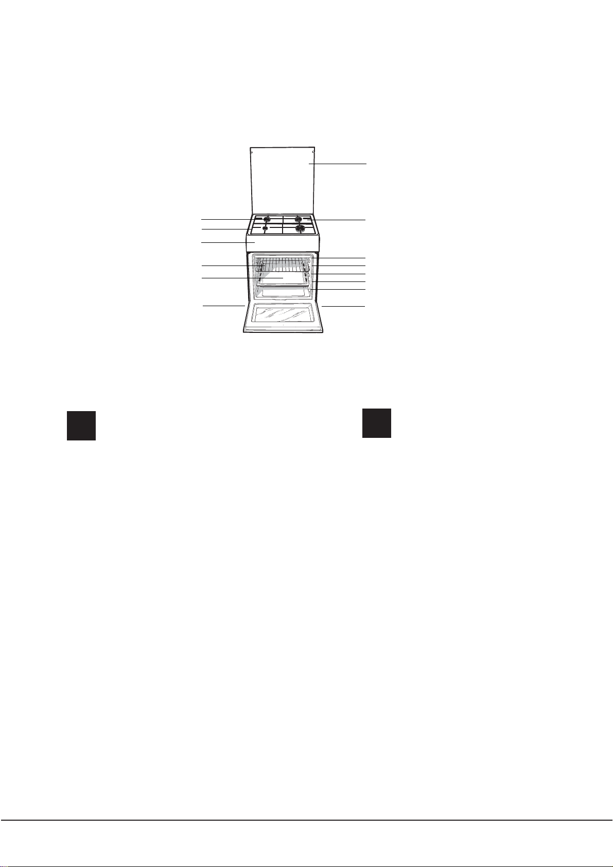
1 Hob burner
Description of the appliance
Overall view
2 Hob Grid
3.Control panel
4.Sliding grill rack
5.DRIPPING pan
6.Adjustable foot
7 Glass Cover
8.Containment surface for spills
9.GUIDE RAILS for the sliding racks
10.position 5
11.position 4
12.position 3
13.position 2
14.position 1
UA
1 Газовий пальник
2 Піддон на випадок переливань
3.Панель управління
4.Полка РЕШІТKИ
5.Полка ДEКО
6.Лапка для налаштування
7 Скляна кришка
8.Пoверхня для збирання збiглoї piдини
9.HAПPABЛЯЮЧІ для полиць
10.положення 5
11.положення 4
12.положення 3
13.положення 2
14.положення 1
Загальнии вигляд
Опис плити
3
Page 4
H5GG5F UA
H5GG5E UA
1
H5GG1E UA
2
2
3
3
4
4
1
GB
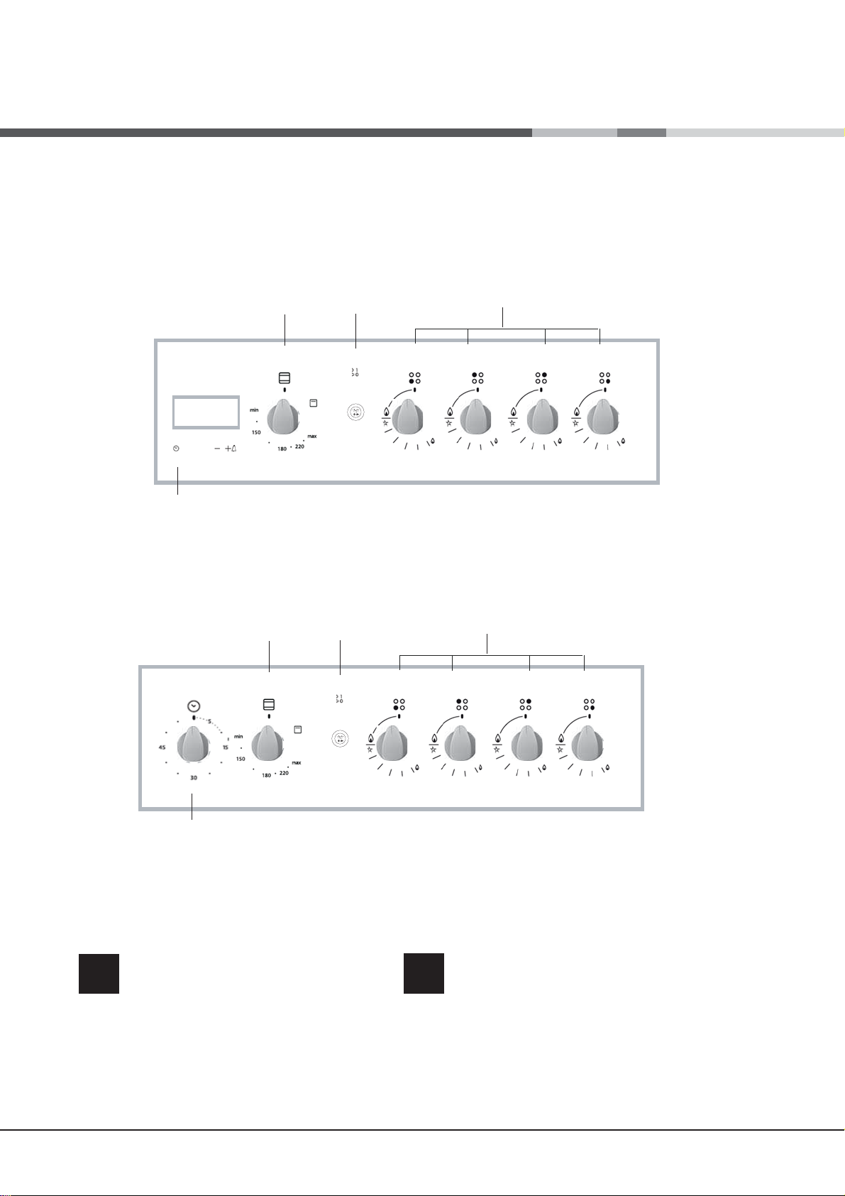
1.TIMER knob
2.OVEN CONTROL knob
3.OVEN LIGHT / ROTISSERIE button
4.Hob BURNER control knob
4
Description of the appliance
Control panel
UA
1.Сукоятка ТАЙМЕРА
2.Ручка ДУХОВКА
3.КНОПКА РОЖНА та ОСВІТЛЕННЯ ДУХОВКИ
4.Ручки для керування газовими
пальниками на варильній поверхні
Панель управління
Опис плити
Page 5
Installation
HOOD
420
Min.
min.
650
mm. with hood
min.
700
mm. without hood
mm.
600
Min. mm.
420
Min. mm.
! Before operating your new appliance please read
this instruction booklet carefully. It contains important
information concerning the safe installation and
operation of the appliance.
! Please keep these operating instructions for future
reference. Make sure that the instructions are kept with
the appliance if it is sold, given away or moved.
! The appliance must be installed by a qualified
professional according to the instructions provided.
! Any necessary adjustment or maintenance must be
performed after the cooker has been disconnected
from the electricity supply.
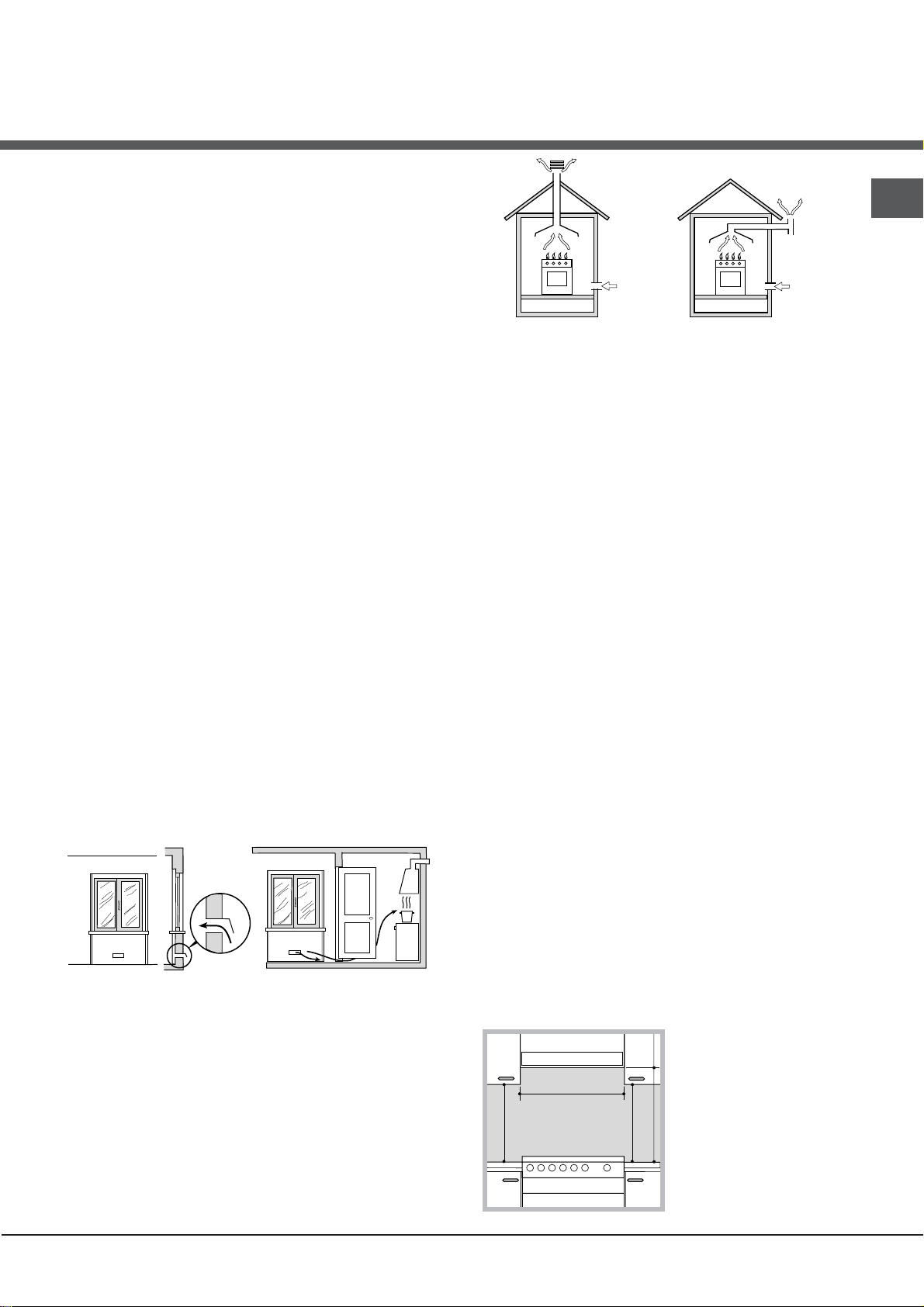
Room ventilation
The appliance may only be installed in permanentlyventilated rooms, according to current national
legislation. The room in which the appliance is installed
must be ventilated adequately so as to provide as
much air as is needed by the normal gas combustion
process (the flow of air must not be lower than 2 m
per kW of installed power).
The air inlets, protected by grilles, should have a duct
with an inner cross section of at least 100 cm
should be positioned so that they are not liable to even
partial obstruction (see gure A).
These inlets should be enlarged by 100% - with a
2
minimum of 200 cm
- whenever the surface of the
hob is not equipped with a flame failure safety device.
When the flow of air is provided in an indirect manner
from adjacent rooms (see gure B), provided that these
are not communal parts of a building, areas with
increased fire hazards or bedrooms, the inlets should
be fitted with a ventilation duct leading outside as
described above.
Adjacent room Room requiring
A B
A
Ventilation opening for
comburent air
Increase in the gap between
the door and the flooring
! After prolonged use of the appliance, it is advisable to
open a window or increase the speed of any fans used.
Disposing of combustion fumes
The disposal of combustion fumes should be
guaranteed using a hood connected to a safe and
efficient natural suction chimney, or using an electric
fan that begins to operate automatically every time the
appliance is switched on (see gure).
2
ventilation
and
GB
Fumes channelled
straight outside
Fumes channelled through
a chimney or branched
flue system reserved for
cooking appliances)
! The liquefied petroleum gases are heavier than air
and collect by the floor, therefore all rooms containing
LPG cylinders must have openings leading outside so
that any leaked gas can escape easily.
LPG cylinders, therefore, whether partially or
completely full, must not be installed or stored in rooms
or storage areas that are below ground level (cellars,
3
/h
etc.). Only the
cylinder being used should be stored in the room; this
should also be kept well away from sources
of heat (ovens, chimneys, stoves) that may cause
the temperature of the cylinder to rise above 50°C.
Positioning and levelling
! It is possible to install the appliance alongside
cupboards whose height does not exceed that of the
hob surface.
! Make sure that the wall in contact with the back of
the appliance is made from a non-flammable, heatresistant material (T 90°C).
To install the appliance correctly:
• Place it in the kitchen, dining room or the bed-sit (not
in the bathroom).
• If the top of the hob is higher than the cupboards,
the appliance must be installed at least 200 mm away
from them.
• If the cooker is installed underneath a wall cabinet,
there must be a minimum distance of 420 mm
between this cabinet and the top of the hob.
This distance should be increased to 700 mm if the
wall cabinets are flammable (see gure).
• Do not position blinds behind the cooker or less than
200 mm away from its
sides.
• Any hoods must be
installed according to
the instructions listed in
the relevant operating
manual.
5
Page 6
GB
Levelling
If it is necessary to level
the appliance, screw the adjustable feet into the places
provided on each corner of the base of the cooker (see
The legs* fit into the slots on the
underside of the base of the
cooker.
Gas connection
Connection to the gas network or to the gas cylinder
may be carried out using a flexible rubber or steel hose,
in accordance with current national legislation and after
).
g.
making sure that the appliance is suited to the type of gas
with which it will be supplied (see the rating sticker on
the cover: if this is not the case see below). When using
liquid gas from a cylinder, install a pressure regulator
which complies with current national regulations. To
make connection easier, the gas supply may be turned
sideways*: reverse the position of the hose holder with
that of the cap and replace the gasket that is supplied
with the appliance.
! Check that the pressure of the gas supply is
consistent with the values indicated in the Table
of burner and nozzle specifications (see below).
This will ensure the safe operation and durability of
your appliance while maintaining efficient energy
consumption.
Electrical connection
Install a standardised plug
indicated on the appliance data
see Technical data table
The appliance must be directly connected to the mains
using an omnipolar circuit-breaker with a minimum contact
opening of 3 mm installed between the appliance and the
mains. The circuit-breaker must be suitable for the charge
indicated and must comply with NFC 15-100 regulations
(the earthing wire must not be interrupted by the circuitbreaker). The supply cable must be positioned so that it
does not come into contact with temperatures higher than
50°C at any point.
Before connecting the appliance to the power supply,
make sure that:
• The appliance is earthed and the plug is compliant with
the law.
• The socket can withstand the maximum power of the
appliance, which is indicated by the data plate.
• The voltage is in the range between the values
indicated on the data plate.
• The socket is compatible with the plug of the
appliance. If the socket is incompatible with the
plug, ask an authorised technician to replace it. Do
not use extension cords or multiple sockets.
! Once the appliance has been installed, the power
supply cable and the electrical socket must be easily
accessible.
! The cable must be checked regularly and replaced
by authorised technicians only.
! The cable must not be bent or compressed.
! The manufacturer declines any liability should
these safety measures not be observed.
corresponding to the load
plate .
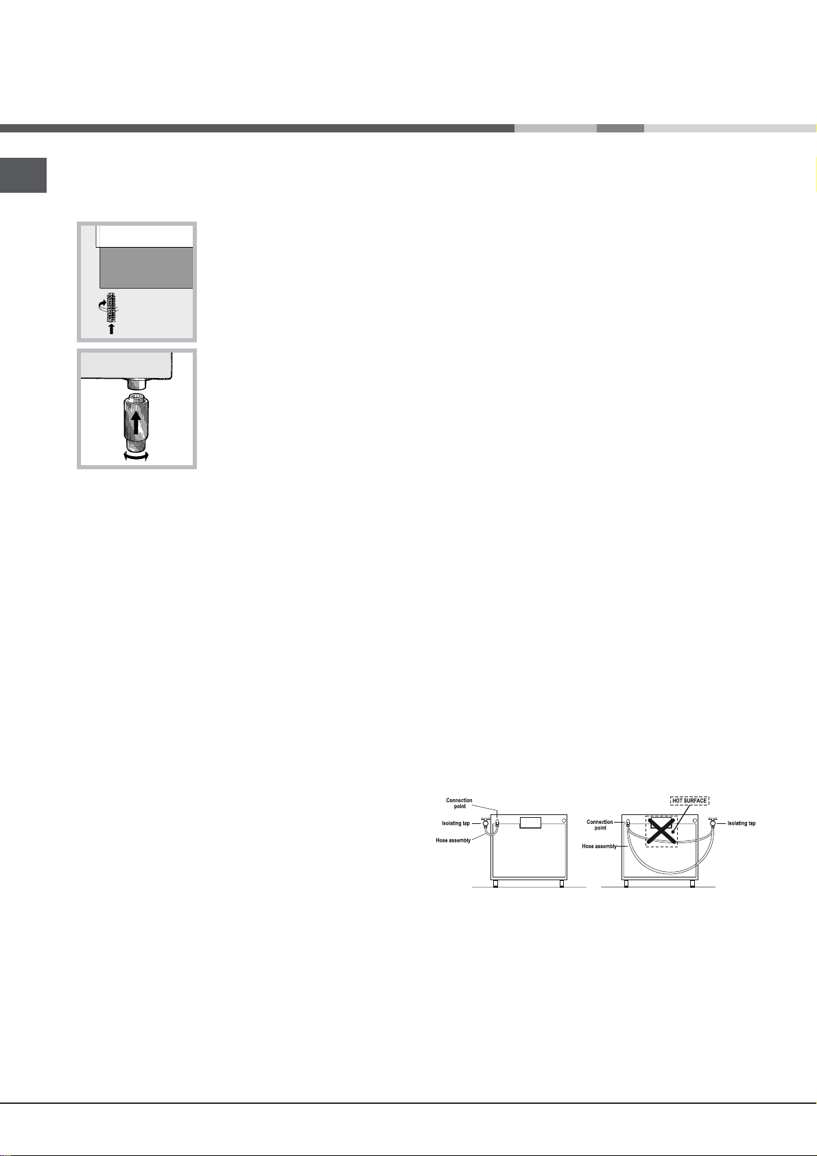
Gas connection using a flexible rubber hose
Make sure that the hose complies with current national
legislation. The internal diameter of the hose must
measure: 8 mm for liquid gas supply; 13 mm for
methane gas supply.
Once the connection has been performed, make sure
that the hose:
• Does not come into contact with any parts that reach
temperatures of over 50°C.
• Is not subject to any pulling or twisting forces and
that it is not kinked or bent.
• Does not come into contact with blades, sharp
corners or moving parts and that it is not
compressed.
• Is easy to inspect along its whole length so that its
condition may be checked.
• Is shorter than 1500 mm.
• Fits firmly into place at both ends, where it will
be fixed using clamps that comply with current
regulations.
! If one or more of these conditions is not fulfilled
or if the cooker must be installed according to the
conditions listed for class 2 - subclass 1 appliances
(installed between two cupboards), the flexible steel
hose must be used instead (see below).
Connecting a flexible jointless stainless steel pipe to
a threaded attachment
Make sure that the hose and gaskets comply with
current national legislation.
To begin using the hose, remove the hose holder on the
appliance (the gas supply inlet on the appliance is a
cylindrical threaded 1/2 gas male attachment).
6
Page 7
A
V
V
I
! Perform the connection in such a way that the hose
length does not exceed a maximum of 2 metres,
making sure that the hose is not compressed and does
not come into contact with moving parts.
Checking the connection for leaks
When the installation process is complete, check the
hose fittings for leaks using a soapy solution. Never
use a flame.
4. Unscrew the nozzle using a
special nozzle socket spanner
(see gure) or with a 7 mm
socket spanner, and replace it
with a new nozzle that is suited
to the new type of gas (see
Burner and nozzle speci cations
table).
GB
Adapting to different types of gas
It is possible to adapt the appliance to a type of gas
other than the default type (this is indicated on the
rating label on the cover).
Adapting the hob
Replacing the nozzles for the hob burners:
1. Remove the hob grids and slide the burners off their
seats.
2. Unscrew the nozzles using a 7 mm socket spanner
(see gure), and replace them with nozzles suited to
the new type of gas(see Burner and nozzle speci cations
table).
3. Replace all the components
by following the above
instructions in reverse.
Adjusting the hob burners’
minimum setting:
1. Turn the tap to the minimum
position.
2. Remove the knob and adjust the regulatory screw,
which is positioned inside or next to the tap pin, until
the flame is small but steady.
! If the appliance is connected to a liquid gas supply,
the regulatory screw must be fastened as tightly as
possible.
3. While the burner is alight, quickly change the position of
the knob from minimum to maximum and vice versa several
times, checking that the flame is not extinguished.
! The hob burners do not require primary air
adjustment.
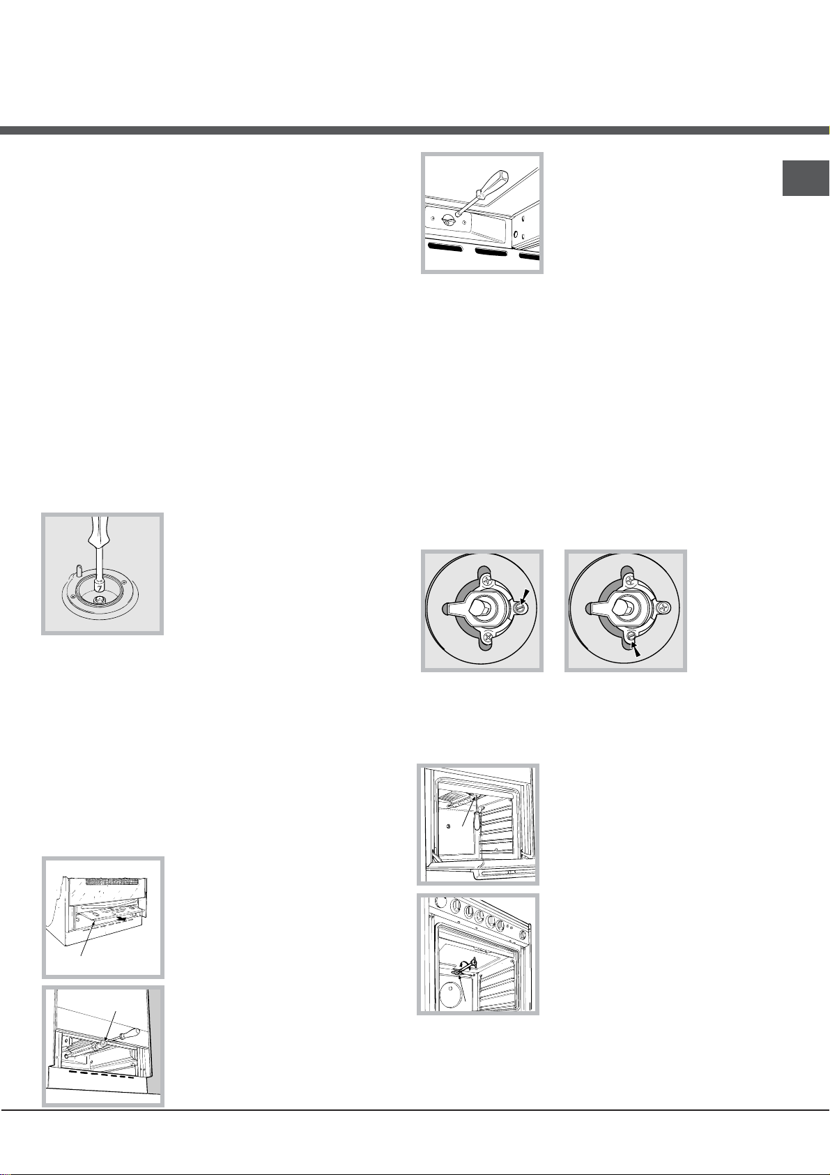
Adapting the oven
Replacing the oven burner nozzle:
1. Remove the oven compartment.
2. Slide out the protection panel A
(see diagram).
3. Remove the oven burner
after unscrewing the screws V
(see gure).
The whole operation will be
made easier if the oven door is
removed.
Adjusting the gas oven
1. Light the burner (see Start-up
burner’s minimum setting:
and Use).
2. Turn the knob to the minimum position (MIN)
after it has been in the maximum position (MAX) for
approximately 10 minutes.
3. Remove the knob.
4. Tighten or loosen the adjustment screws on the
outside of the thermostat pin (see gure) until the flame
is small but steady.
! If the appliance is connected to liquid gas, the
adjustment screw must be fastened as tightly as
possible.
5. Turn the knob from the MAX position to the MIN
position quickly or open and shut the oven door,
making sure that the burner is not extinguished.
Adapting the grill
Replacing the grill burner nozzle:
1. Remove the oven burner after loosening screw V
(see gure).
2. Unscrew the grill burner
nozzle using a special nozzle
socket spanner (see gure) or
preferably with a 7 mm socket
spanner, and replace it with a
new nozzle that is suited to the
new type of gas (see Burner and
nozzle speci cations table).
! Be careful of the spark plug
wires and the thermocouple
tubes.
The oven and grill burners do
!
not require primary air adjustment.
! After adjusting the appliance so it may be used with
a different type of gas, replace the old rating label with
a new one that corresponds to the new type of gas
(these labels are available from Authorised Technical
Assistance Centres).
7
Page 8
GB
S
S
R
A
! Should the gas pressure used be different (or vary
slightly) from the recommended pressure, a suitable
pressure regulator must be fitted to the inlet hose in
accordance with current national regulations relating to
“regulators for channelled gas”.
We recommend cleaning the oven before using it for
the first time, following the instructions provided in the
„Care and maintenance” section.
TECHNICAL DATA
Oven dimensions
(HxWxD)
Volume
Useful
measurements
relating to the oven
compartment
Power supply voltage
and frequency
Burners
34x38x44 cm
57 l
width 42 cm
depth 44 cm
height 17 cm
see data plate
may be adapted for use with any
type of gas shown on the data
plate, which is located inside the
flap or, after the oven
compartment has been opened,
on the left-hand wall inside the
oven.
EC Directives: 2006/95/EC dated
12/12/06 (Low Voltage) and
subsequent amendments 2004/108/EC dated 15/12/04
(Electromagnetic Compatibility)
and subsequent amendments 2009/142/EC dated 30/11/09
(Gas) and subsequent
amendments - 93/68/EEC dated
22/07/93 and subsequent
amendments - 2002/96/EC.
1275/2008 (Stand-by/ Off mode)
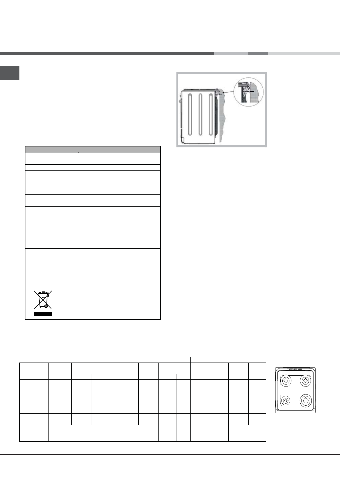
Safety Chain
! In order
to prevent
accidental
tipping of the
appliance, for
example by
a child climbing onto the
oven door, the
supplied safety
chain MUST be
installed!
The cooker is fitted with a safety chain to be fixed by
means of a screw (not supplied with the cooker) to
the wall behind the appliance, at the same height as
the chain is attached to the appliance.
Choose the screw and the screw anchor according
to the type of material of the wall behind the appliance. If the head of the screw has a diameter smaller
than 9mm, a washer should be used. Concrete wall
requires the screw of at least 8mm of diameter, and
60mm of length.
Ensure that the chain is fixed to the rear wall of the
cooker and to the wall, as shown in figure, so that
after installation it is tensioned and parallel to the
ground level.
Table of burner and nozzle specifications
Table 1 Liquid Gas Natural Gas
Burner Diameter
Fast
(Large)(R)
Semi Fast
(Medium)(S)
Auxiliary
(Small)(A)
Oven - 2.80 1.0 46 80 204 200 119 267 132 257
Grill - 2.30 - - 75 167 164 114 219 139 227
Supply
Pressures
* At 15°C 1013 mbar-dry gas *** Butane P.C.S. = 49,47 MJ/Kg
** Propane P.C.S. = 50,37 MJ/Kg Natural P.C.S. = 37,78 MJ/m³
8
(mm)
Nominal Reduced (mm) (mm) *** ** (mm) (mm)
100 3.00 0.7 41 87 218 214 128 286 145 286
75 1.90 0.4 30 69 138 136 104 181 115 181
51 1.00 0.4 30 50 73 71 78 95 85 95
Thermal Power
kW (p.c.s.*)
Nominal (mbar)
Minimum (mbar)
Maximum (mbar)
By Pass
1/100
Nozzle
1/100
Flow*
28-30
20
35
g/h
37
25
45
Nozzle
1/100
20
17
25
Flow*
l/h
Nozzle
1/100
Flow*
13
6,5
18
l/h
H5GG5F UA
H5GG5E UA
H5GG1E UA
Page 9

Start-up and use
F
X
C
Using the hob
Lighting the burners
For each BURNER knob there is a complete ring showing
the strength of the flame for the relevant burner.
To light one of the burners on the hob:
1. Bring a flame or gas lighter close to the burner.
2. Press the BURNER knob and turn it in an
anticlockwise direction so that it is pointing to the
maximum flame setting .
3. Adjust the intensity of the flame to the desired level
by turning the BURNER knob in an anticlockwise
direction. This may be the minimum setting , the
maximum setting or any position in between the two.
If the appliance is fitted with an electronic lighting
device* (see gure), press the ignition button, marked
with the symbol
hold the BURNER knob down
and turn it in an anticlockwise
direction, towards the
maximum flame setting, until
the burner is lit.
Several models are equipped
with an ignition device
which is built into the knob; in this case the electronic
ignition device* is present (C) but the ignition button
is not. Simply press the BURNER knob and turn it
in an anticlockwise direction so that it is pointing
to the maximum flame setting, until the burner is lit.
The burner may be extinguished when the knob is
released. If this occurs, repeat the operation, holding
the knob down for a longer period of time.
Flame adjustment according to levels
the burner flame intensity can be adjusted with the
knob according to 6 power levels, from maximum
to minimum with 4 intermediate positions:
a click will indicate the change from one level to
another when turning the knob . The system
guarantees a more precise adjustment, allows
to replicate the flame intensity and to identify
easily the preferred level for different cooking
operations.
, then
Burner ř Cookware diameter (cm)
GB
Fast (R) 24 - 26
Semi Fast (S) 16 - 20
Auxiliary (A) 10 - 14
To identify the type of burner, please refer to the
diagrams contained in the “Burner and nozzle
specifications”.
Using the oven
! The first time you use your appliance, heat the empty
oven with its door closed at its maximum temperature
for at least half an hour. Ensure that the room is well
ventilated before switching the oven off and opening
the oven door. The appliance may emit a slightly
unpleasant odour caused by protective substances
used during the manufacturing process burning away.
! Before operating the product, remove all plastic film
from the sides of the appliance.
! Never put objects directly on the bottom of the oven;
this will avoid the enamel coating being damaged.
Only use position 1 in the oven when cooking with the
rotisserie spit.
Lighting the oven
To light the oven burner, bring a flame or gas lighter
close to opening F (see gure) and press the OVEN
control knob while turning it in an anticlockwise
direction until it reaches the MAX position.
If, after 15 seconds, the burner
is still not alight, release the
knob, open the oven door and
wait for at least 1 minute before
trying to light it again.
! The oven is fitted with a
safety device and it is therefore
necessary to hold the OVEN
control knob down for approximately 6 seconds.
! If the flame is accidentally extinguished, switch off the
! If the flame is accidentally extinguished, switch off the
burner and wait for at least 1 minute before attempting
to relight it.
If the appliance is equipped with a flame failure safety
device*(X), press and hold the BURNER knob for
approximately 2-3 seconds to keep the flame alight
and to activate the device.
To switch the burner off, turn the knob until it reaches
the stop position •.
burner and wait for at least 1 minute before attempting
to relight the oven.
Practical advice on using the burners
WARNING! The glass lid can break
For the burners to work in the most
in if it is heated up. Turn off all the
efficient way possible and to save
burners and the electric plates before
closing the lid. *Applies to the models
with glass cover only.
9
Page 10

GB
A
S
D
Adjusting the temperature
To set the desired cooking temperature, turn the
OVEN control knob in an anticlockwise direction.
Temperatures are displayed on the control panel and
may vary between MIN (140°C) and MAX (250°C).
Once the set temperature has been reached, the oven
will keep it constant by using its thermostat.
Grill
To light the grill, bring a flame or gas lighter close to
the burner and press the OVEN control knob while
turning it in a clockwise direction until it reaches the
position. The grill enables the surface of food to be
browned evenly and is particularly suitable for roast
dishes, schnitzel and sausages. Place the rack in
position 4 or 5 and the dripping pan in position 1 to
collect fat and prevent the formation of smoke.
! The grill is fitted with a safety device and it is
therefore necessary to hold the OVEN control knob
down for approximately 6 seconds.
! If the flame is accidentally extinguished, switch off the
burner and wait for at least 1 minute before attempting
to relight the grill.
! When using the grill, leave the oven door ajar,
positioning the deflector D between the door and the
control panel (see gure) in order to prevent the knobs
from overheating.
Lower compartment
There is a compartment underneath the oven that may
be used to store oven accessories or deep dishes. To
open the door pull it downwards (see gure).
! The internal surfaces of
the compartment (where
present) may become
hot.
! Do not place
flammable materials
in the lower oven
compartment.
In gas cooker models,
there is a sliding protection layer A that shields the
lower compartment from the heat generated by the
burner (see gure).
To remove the sliding
protection remove the screw S
(see gure). To replace it, lock it
in place with the screw S.
! Before using the oven make
sure that the sliding protection
is fixed correctly.
Turnspit
To operate the rotisserie (see
1. Place the dripping pan in
2. Place the rotisserie support in
position 4 and insert the spit in the hole provided on the
back panel of the oven.
Oven light
The light may be
moment by pressing the
switched on at any
diagram
position 1.
3. Acitvate the function
by pressing the
TURNSPIT button.
OVEN LIGHT button.
) proceed as follows:
WARNING! The oven is provided with
a stop system to extract the racks and
prevent them from coming out of the
oven.(1)
As shown in the drawing, to extract them
completely, simply lift the racks, holding
them on the front part, and pull (2).
Timer*
To activate the Timer proceed as follows:
1. Turn the TIMER knob in a clockwise direction for
almost one complete revolution to set the buzzer.
2. Turn the TIMER knob in an anticlockwise direction
to set the desired length of time.
* Only available in certain models.
10
Page 11

Electronic timer
*
This function displays the time and works as a timer
which counts down to zero.
! All functions will be implemented approximately 7
seconds after they have been set.
Resetting the clock
After the appliance has been connected to the power
supply, or after a power cut, the clock display will
begin to blink, showing the figure: 0:00
• Press button
and then buttons - and + to set the
exact time. Press and hold the buttons to quicken
the count upwards.
Any necessary modifications can be made by
repeating the above process.
Timer feature
This function may be accessed by pressing the
button, after which the display will show the symbol
. Every time the + button is pressed it corresponds
to a time increase of 10 seconds, until it reaches 99
minutes and 50 seconds. After this point, each press of
the button represents an increase of one minute, up to
a maximum of 10 hours.
button reduces the time.
Pressing the
-
After the time period has been set, the timer will begin
to count down. When the timer reaches zero, the
buzzer will sound (this may be stopped by pressing
any button).
The time may be displayed by pressing the
and the
symbol indicates that the timer function has
button,
been set. After approximately 7 seconds, the display
will automatically revert to the timer.
Cancelling a time that has already been set
Press the
button until the display shows 0:00.
–
Adjusting the buzzer volume
After selecting and confirming the clock settings, use
button to adjust the volume of the alarm buzzer.
–
the
GB
Oven cooking advice table
Foods
Pasta
Lasagne
Cannelloni
Gratin dishes
Meat
Veal
Chicken
Duck
Rabbit
Pork
Lamb
Fish
Mackerel
Dentex
Trout baked in foil
Pizza
Neapolitan-style
Pies
Biscuits
Tart
Savoury pies
Leavened cakes
Grilled foods
Veal steak
Cutlets
Hamburgers
Mackerel
Toast
Grilling using the rotisserie
Spit-roast veal
Spit-roast ch icken
Grilling using the multi-spit rotisserie*
Meat kebabs
Vegetable kebabs
Weight (in
kg)
2.5
2.5
2.5
1.5
1.5
1.8
2.0
2.1
1.8
1.1
1.5
1.0
1.0
0.5
1.1
1.0
1.0
1
1.5
1
1
4 pcs
1
2
1
0.8
Rack
position
4
4
4
3
3
3
3
3
3
3
3
3
4
4
4
4
4
4
4
3
4
4
-
-
-
-
Preheating time (min)
200-210
200-210
210-220
180-200
180-200
180-200
210-220
200
200
200
200
200
200
180
190
180
170
5
5
5
5
5
5
5
5
5
Only available in certain models.*
Recommended
Temperature (°C)
10
10
10
10
10
10
10
10
10
10
10
10
15
15
15
15
15
Cooking time
(minutes)
100-110
100-105
75-80
50-60
50-60
95-100
90-100
70-80
70-80
45-50
45-55
45-50
20-25
25-35
40-45
50-55
40-45
15-20
20
20-30
15-20
4-5
70-80
70-80
40-45
25-30
11
Page 12

Precautions and tips
GB
! This appliance has been designed and manufactured in
compliance with international safety standards.
The following warnings are provided for safety reasons and
must be read carefully.
General safety
• These instructions are only valid for the countries
whose symbols appear in the manual and on the serial
number plate.• The appliance was designed for domestic
use inside the home and is not intended for commercial or
industrial use.
• The appliance must not be installed outdoors, even in
covered areas. It is extremely dangerous to leave the
appliance exposed to rain and storms.
• Do not touch the appliance with bare feet or with wet or
damp hands and feet.
• The appliance must be used by adults only for
the preparation of food, in accordance with the
instructions outlined in this booklet. Any other
use of the appliance (e.g. for heating the room)
constitutes improper use and is dangerous.
The manufacturer may not be held liable for any
damage resulting from improper, incorrect and
unreasonable use of the appliance.
• The instruction booklet accompanies a class 1 (insulated)
or class 2 - subclass 1 (recessed between 2 cupboards)
appliance.
• Keep children away from the oven.
• Make sure that the power supply cables of other electrical
appliances do not come into contact with the hot parts of
the oven.
• The openings used for the ventilation and dispersion of
heat must never be covered.
• Do not close the glass hob cover (selected models only)
when the burners are alight or when they are still hot.
• Always use oven gloves when placing cookware in the
oven or when removing it.
• Do not use flammable liquids (alcohol, petrol, etc...) near
the appliance while it is in use.
• Do not place flammable material in the lower storage
compartment or in the oven itself. If the appliance is
switched on accidentally, it could catch fire.
• Always make sure the knobs are in the • position and that
the gas tap is closed when the appliance is not in use.
• When unplugging the appliance, always pull the plug from
the mains socket; do not pull on the cable.
• If the appliance breaks down, under no circumstances
should you attempt to repair the appliance yourself.
Repairs carried out by inexperienced persons may cause
injury or further malfunctioning of the appliance. Contact
Assistance.
• Do not rest heavy objects on the open oven door.
• The appliance should not be operated by people
(including children) with reduced physical, sensory
or mental capacities, by inexperienced individuals
or by anyone who is not familiar with the product.
These individuals should, at the very least, be
supervised by someone who assumes responsibility
for their safety or receive preliminary instructions
relating to the operation of the appliance.
• Do not let children play with the appliance.
•
If the cooker is placed on a pedestal, take the necessary precautions to prevent the cooker from sliding
off the pedestal itself.
Disposal
• When disposing of packaging material: observe local
legislation so that the packaging may be reused.
• The European Directive 2002/96/EC relating to Waste
Electrical and Electronic Equipment (WEEE) states that
household appliances should not be disposed of using
the normal solid urban waste cycle. Exhausted appliances
should be collected separately in order to optimise
the cost of re-using and recycling the materials inside
the machine, while preventing potential damage to the
atmosphere and to public health. The crossed-out dustbin
is marked on all products to remind the owner of their
obligations regarding separated waste collection.
Exhausted appliances may be collected by the public
waste collection service, taken to suitable collection areas
in the area or, if permitted by current national legislation,
they may be returned to the dealers as part of an
exchange deal for a new equivalent product.
All major manufacturers of household appliances
participate in the creation and organisation of systems for
the collection and disposal of old and disused appliances.
Respecting and conserving the environment
• You can help to reduce the peak load of the electricity
supply network companies by using the oven in the hours
between late afternoon and the early hours of the morning.
• Check the door seals regularly and wipe them clean to
ensure they are free of debris so that they adhere properly
to the door, thus avoiding
heat dispersion.
• Never perform any cleaning or maintenance work without
having disconnected the appliance from the electricity
mains.
12
Page 13

Care and maintenance
Switching the appliance off
Disconnect your appliance from the electricity supply
before carrying out any work on it.
Cleaning the appliance
! Do not use abrasive or corrosive detergents such as
stain removers, anti-rust products, powder detergents
or sponges with abrasive surfaces: these may scratch
the surface beyond repair.
! Never use steam cleaners or pressure cleaners on
the appliance.
• It is usually sufficient simply to wash the hob using a
damp sponge and dry it with absorbent kitchen roll.
• The stainless steel or enamel-coated external parts
and the rubber seals may be cleaned using a
sponge that has been soaked in lukewarm water
and neutral soap. Use specialised products for the
removal of stubborn stains. After cleaning, rinse well
and dry thoroughly. Do not use abrasive powders or
corrosive substances.
• The hob grids, burner caps, flame spreader rings
and the hob burners can be removed
to make cleaning easier; wash them in hot water and
non-abrasive detergent, making sure all burnt-on
residue is removed before drying them thoroughly.
• For hobs with electronic ignition, the terminal part of
the electronic lighting devices should be cleaned
frequently and the gas outlet holes should be
checked for blockages.
• The inside of the oven should ideally be cleaned
after each use, while it is still lukewarm. Use hot
water and detergent, then rinse well and dry with a
soft cloth. Do not use abrasive products.
Clean the glass part of the oven door using a
•
sponge and a non-abrasive cleaning product, then
dry thoroughly with a soft cloth. Do not use rough
abrasive material or sharp metal scrapers as these
could scratch the surface and cause the glass to
crack.
• The accessories can be washed like everyday
crockery, and are even dishwasher safe.
• Stainless steel can be marked by hard water that
has been left on the surface for a long time, or by
aggressive detergents containing phosphorus.
After cleaning, rinse well and dry thoroughly. Any
remaining drops of water should also be dried.
The cover
If the cooker is fitted with
a glass cover, this cover
should be cleaned using
lukewarm water. Do not
use abrasive products.
It is possible to remove
the cover in order to make
cleaning the area behind
the hob easier. Open
the cover fully and pull it
! Do not close the cover when the burners are alight or
when they are still hot.
Inspecting the oven seals
Check the door seals around the oven periodically. If
the seals are damaged, please contact your nearest
Authorised After-sales Service Centre. We recommend
that the oven is not used until the seals have been
replaced.
upwards (see gure).
Gas tap maintenance
Over time, the taps may become jammed or difficult to
turn. If this occurs, the tap must be replaced.
! This procedure must be performed by a qualified
technician who has been authorised by the
manufacturer.
Replacing the oven
light bulb
1. After disconnecting the
oven from the electricity mains,
remove the glass lid covering
the lamp socket (see gure).
2. Remove the light bulb and
replace it with a similar one: voltage 230 V, wattage 25
W, cap E 14.
3. Replace the lid and reconnect the oven to the
electricity supply.
! Do not use the oven lamp as/for ambient lighting.
Assistance
Please have the following information handy:
• The appliance model (Mod.).
• The serial number (S/N).
This information can be found on the data plate located
on the appliance and/or on the packaging.
GB
13
Page 14

GB
Removing and fitting the oven door:
Removing and fitting the oven door:
1.Open the door
2.Make the hinge clamps of the oven door rotate
backwards completely (see photo)
3. Close the door until the clamps stop (the door will
remain open for 40° approx.) (see photo)
404040
°
6.Replace the glass.
WARNING! Oven must not be operated with inner
WARNING! Oven must not be operated with inner
WARNING! Oven must not be operated with inner
door glass removed!
door glass removed!
door glass removed!
WARNING! When reassembling the inner door
WARNING! When reassembling the inner door
WARNING! When reassembling the inner door
glass insert the glass panel correctly so that the
glass insert the glass panel correctly so that the
glass insert the glass panel correctly so that the
inscription written on the panel is not reversed and
inscription written on the panel is not reversed andinscription written on the panel is not reversed and
can be easily legible.
can be easily legible.
can be easily legible.
7.Replace the profile, a click will indicate that the
part is positioned correctly.
8.Open the door completely.
9.Close the supports (see photo).
4.Press the two buttons on the upper profile and
extract the profile (see photo)
5.Remove the glass sheet and do the cleaning as
indicated in chapter: "Care and maintenance".
10.Now the door can be completely closed and the
oven can be started for normal use.
14
Page 15

Встановлення
HOOD
420
Min.
min.
650
mm. with hood
min.
700
mm. without hood
mm.
600
Min. mm.
420
Min. mm.
! Важливо зберегти цю брошуру, щоб можна було
до неі звернутися при необхідності у будь-якому
випадку. У разі продажу, передачi iншiи особi
або переізду, переконаитеся в тому, що вона
залишається разом з виробом.
! Уважно прочитаите інструкціі: інформація про
обладнання, використання и безпеку грає дуже
важливу роль.
! Установка
вироба має виконуватися згідно даноі
інструкціі кваліфікованим персоналом.
! Будь-яке втручання в регулювання або технічне
обслуговування має виконуватися на плиті,
відключеніи від електроживлення.
Вентиляція приміщень
Обладнання може бути встановлене тільки у
постіино вентильованих приміщеннях, згідно діючим
нормам в краінi, де вироб буде викорисовано. У
приміщенні, в якому встановлено обладнання, має
відбуватися зміна повітря, у ступені, необхідному
для нормального горіння газу (швидкість зміни
3
повітря не має бути меншою 2м
/год на кожнии кВт
встановленоі потужності).
Вхід приточноі вентиляціі, захищении ґраткою, повинен
2
мати корисну площу не менше 100 см
корисного
перетину і має бути розміщении так, щоб він не міг
забитися, навіть частково ( див. малюнок A).
Такии вхід повинен бути збільшении на 100%, тобто
2
мінімум 200 см
– якщо робоча поверхня плити не
має пристрою безпеки у разі зникнення полум’я, і
коли можливии непрямии потік повітря із прилеглих
приміщень (див.малюнок B) – якщо це не спільні
частини будівлі, пожежонебезпечне приміщення
або спальні кімнати, обладнані вентиляціиним
трубопроводом назовні, як описано вище.
B
Прилеглі
приміщення
A
Вентильовані
приміщення
A
Вентиляціинии отвір для
відпрацьованого повітря
Збільшення щілини між
дверима і підлогою
! Після тривалого використання плити, доцільно
відкрити
вікно або збільшити швидкість
вентиляторів.
Відведення продуктів згорання
Відведення
безпосередньо
назовні
Відведення через канал або
розгалужении димар
(зарезервовании для
кухонного устаткування)
! Зріджені нафтові гази, важчі за повітря, бираються
внизу, тому приміщення
, де знаходяться балони з
газом, повинні бути обладнані витяжними отворами,
що виходять назовні для евакуаціі знизу при
можливому витоку газу.
Балони із зрідженим нафтовим газом, порожні або
частково повні, не повинні бути встановлені або
берігатися в приміщеннях нижче за рівень грунту
(льохи і т.п.). У приміщенні можна тримати тільки
використовувании балон, далеко від джерел тепла
(печі, каміни, обігрівачі), які нагріваються вище від
50°C.
Розміщення і вирівнювання
! Можна встановлювати плиту збоку від меблів, які
не вищі за робочу поверхню.
! Переконаитеся в тому, що поверхня стіни, яка
контактує із задньою частиною плити, виготовлена
з негорючого та теплостіикого матеріалу і витримує
нагрівання (90°C).
Для правильного встановлення
• розміщуите плиту в кухні, обідніи залі або в
однокімнатніи квартирі-студіі (не
• якщо поверхня плити є трохи вищою, ніж
поверхня меблів, меблі повинні знаходитися не
ближче ніж 200 мм від плити;
• якщо плита буде встановлена під секцією навісних
меблів, esso відстань до іі поверхні не повинна
бути меншою за 420 мм.
Така відстань повинна складати 700 мм, якщо
секція навісних меблів зроблена з
матеріалу (див. малюнок);
• не розміщуите занавісок позаду плити або ближче
ніж 200 мм від іі сторін;
• витяжки повинні встановлюватися згідно вказівкам
відповідноі інструкціі.
у ванні);
горючого
UA
Відведення продуктів згорання має бути
забезпечене через витяжку, підключену до каналу з
природною тягою з належною ефективністю, або за
допомогою електровентилятора, якии би включався
автоматично кожного разу при включенні плити (див.
малюнки).
15
Page 16

UA
Вирівнювання
Якщо необхідно вирівняти
плиту, вкрутіть регулюючі
ніжки, що входять до
комплекту постачання,
у спеціальні місця, що
знаходяться у кутках основи
(див. малюнок).
Ніжки* вмонтовуються у гнізда
під основою плити.
Підключення газу
Підключення до газовоі мережі або балона може
виконуватися за допомогою гнучкого гумового шланга
або шланга в сталевому обплетенні, згідно діючим
національним нормам і після того, як встановлено,
що плита була налаштована на тип газу, на якому
вона працюватиме (див. Калібрувальна бирка на
кришці: в іншому випадку див. нижче). У разі
плити від балона із зрідженим газом, використовуите
редуктори відповідно до діючих норм у странi,
де буде використовано вироб. Щоб полегшити
підключення, живлення газу може подаватися
збоку *: переставте в обратному напрямi утримувач
гумки для підключення замикаючоі пробки і замініть
ущільнювач, що входить у комплект постачання.
роботи
Підключення електроенергіі
Встановіть на кабелі вилку, розраховану на
навантаження, вказане на табличці з технічними
характеристиками, розміщеніи на плиті (див.
таблицю Технічних Даних).
У разі прямого підключення до мережі необхідно
помістити між плитою і мережею всеполярнии
вимикач з мінімальною відстанню між контактами 3
мм, розраховании на вказане навантаження і такии,
що відповідає нормі NFC 15-100 (дріт заземлення
повинен перериватися вимикачем). Кабель живлення
повинен бути розташовании так, щоб жодна з иого
частин не піддавалася нагріванню вище, ніж на 50°C
від температури довкілля.
До виконання підключення переконаитеся, що:
• розетка має заземлення, відповідно до встановлених
норм;
• розетка витримує максимальне навантаження
потужності обладнання, вказане на табличці з
характеристиками;
• напруга живлення
знаходиться в межах значень,
вказаних на табличці;
• розетка сумісна з вилкою плити. В іншому випадку
замініть розетку або вилку; не використовуите
подовжувачі и тріиники.
! У встановленіи плиті, має бути забезпечении
легкии доступ до електричного кабелю і розетки.
! Кабель не повинен мати перегинів або бути
стиснутим.
! Кабель має періодично перевірятися і мінятися
тільки фахівцями.
! Підприємство не несе будь-якоі
відповідальності, якщо ці норми не
дотримуватимуться.
не
! Для безперебіиноі роботи, для
адекватного
використання енергіі і для більшого терміну служби
плити, забезпечте тиск подачі газу в межах значень,
вказаних в таблиці Характеристик пальників і
форсунок (див. нижче).
Підключення газу за допомогою гнучкого
гумового шланга
Перевірте, щоб шланг відповідав діючим державним
нормам. Внутрішніи діаметр шланга повинен бути: 8
мм для зрідженого газу; 13 мм для метану.
Виконавши з’єднання, переконаитеся в тому, що
шланг:
• не торкається частин, які нагріваються вище
температури в 50оC;
• не має будь-якого натягнення або скручування, не
має згинів або стискань;
• не торкається гострих предметів, краів, рухомих
частин і не здавлении;
• може бути легко оглянутии по всіи довжині для
контролю иого
стану;
• має довжину меншу ніж 1500 мм;
• добре закріплении на обох кінцях за допомогою
хомутів, відповідно до діючих державних норм.
! Якщо одна або більше з цих умов не будуть
дотримані, або якщо плита встановлена згідно
умовам класу 2 - підклас 1 (плита, встановлена між
двома шафами), необхідно використовувати гнучкии
шланг в сталевому обплетенні (див. нижче).
Точк а
кріплення
Відсічний
кран
Блок гнучки
труб
Точк а
кріплення
Блок гнучки
труб
ГАРЯЧА ПОВЕРХНЯ
Відсічний
кран
Підключення газу за допомогою гнучкого шланга
в обплетенні з неіржавіючоі сталі до безперервноі
стіни за допомогою патронів із різьбою
Перевірте, щоб шланг і обплетення відповідали
діючим державним нормам.
16
Page 17

A
V
Щоб підключити шланг, видаліть утримувач гумки, що
V
I
міститься в плиті (місце підключення газу до плити має
вигляд цилiндричноі трубки з різьбою папа 1/2 дюима)
! Виконаите з’єднання так, щоб довжина
трубопроводу не перевищувала 2 метрів, при
цьому не допускаите контакту шланга з рухомими
частинами та иого стиснення.
Контроль герметичності
Після повного
встановлення перевірте герметичність
всіх з’єднань, використовуючи тільки мильнии
розчин і у жодному випадку сірник.
Адаптація до різних типів газу
Є можливість налаштування плити під тип газу,
відміннии від типу, на якии вона була налаштована
підприємством-виробником (вказании на
калібрувальніи бирці на кришці).
Налаштування робочоі поверхні
Заміна форсунок пальників поверхні:
1. Зніміть ґратки и пальники з іх посадочних місць;
2. Відгвинтіть форсунки, користуючись трубним
ключем 7 мм (див. малюнок), і замініть іх
форсунками,
новому типу газу (див.
таблицю Характеристики
пальників і форсунок);
3. Встановіть на місце всі
компоненти, виконавши
вказані вище операціі у
зворотніи послідовності.
що відповідають
3. видаліть пальник духовки
після того, як відкрутите гвинти
V (див. малюнок);
процедуру виконати легше,
якщо зняти дверцята духовки.
4. відгвинтіть форсунку пальника
спеціальним трубним ключем
для форсунок (див. малюнок)
або трубним ключем 7 мм
і замініть іі форсункою, що
відповідає новому типу газу
(див. таблицю Характеристики
пальників і форсунок).
Налаштування мінімального
в пальник
духовки:
рівня подачі газу
1. запаліть пальник (див. Включення і Використання);
2. встановіть рукоятку у положення мінімуму (МІН)
після того, як вона залишалася приблизно протягом
10 хвилин у максимальному положенні (MAКС);
3. зніміть рукоятку;
4. користуючись регулювальним гвинтом на
зовнішніи стороні стрижня термостата (див.
малюнки),
добиитеся маленького стіикого полум’я.
! У разі зріджених газів, регулювальнии гвинт
повинен бути вкручении до упору;
5. Перевірте, щоб, при швидкому обертанні
рукоятки з положення MAКС у положення МІН або
UA
Налаштування мінімального рівня пальників
поверхні:
1. встановіть кран у мінімальне положення;
2. зніміть рукоятку і користуючись регулювальним
гвинтом, що знаходиться на внутрішніи частині
або збоку на стрижні крана
, добиитеся маленького
стабільного полум’я.
! У разі зріджених газів, регулювальнии гвинт
повинен бути вкручении до упору;
3. перевірте, щоб при швидкому обертанні крана з
максимального в мінімальне положення, пальник не
гаснув.
! Пальники робочоі поверхні не потребують
регулювання первинного повітря.
Налаштування духовки
Заміна форсунки пальника духовки:
1. витягніть коробку духовки;
витягніть висувнии захист
2.
A (див. малюнок);
при швидкому відкритті і закриті дверцят духовки
пальник не гаснув.
Налаштування гриля
Заміна форсунки пальника гриля:
1. видаліть пальник гриля після того, як відкрутите
гвинти V (див. малюнок);
2. відгвинтіть форсунку
пальника гриля, користуючись
спеціальним трубним ключем
для форсунок (див. малюнок)
або трубним ключем 7 мм
і замініть іі форсункою, що
відповідає новому
типу газу
(див. таблицю
Характеристики пальників і
форсунок).
17
Page 18

UA
S
S
R
A
! Зверніть увагу на кабелі запальних свічок і трубки
термопар.
! Пальники духовки та гриля не потребують
регулювання первинного повітря.
! Після налаштування на газ, що відрізняється від
газу при випробуваннях на підприємстві-виробнику,
замініть стару калібрувальну бирку новою, з
зазначенням нового
газу, одержану в Авторизованих
сервiсних центрах.
! Якщо тиск газу відрізнятиметься (або мінятиметься)
від раніше встановленого, необхідно встановити на
вході редуктор тиску, згідно діючим національним
нормам для “редукторів для каналізованих газів”.
ТЕХНІЧНІ ДАНІ
Розміри Духовки
ВxШxГ
Об'єм
Корисні
розміри
коробки
духовки
34x38x44 см
57
літрiв
ширина см 42
глибина см 44
висота см 17
Напруга та
частота
живлення
Див. на табличці з даними
Налаштовуються на всі типи
газу, вказані на табличці з
Пальники
даними, розташованій в
середині виступу, або, коли
відкривається духовка, на
внутрішній лівій стінці.
Директиви ЄС: 2006/95/EC від
12/`2/06 (Низька Напруга) та
подальші зміни - 2004/108/EC
від 15/12/04 (Електромагнітна
сумісність) та подальші зміни -
2009/142/EC від 30/11/09
(Gas) та подальші зміни -
93/68/EEC від 22/07/93 та
подальші зміни - 2002/96/EC.
1275/2008 (Stand-by/ Off mode)
Перш ніж розпочати використання духовкою,
рекомендується очистити її, дотримуючись
рекомендацій, наведених у параграфі “Технічне
обслуговування і догляд”.
Безпека ланцюга
! Щоб
запобігти
випадковому
перекиданню
приладу,
наприклад,
коли дитина
залазить
на дверцята
духової шафи,
НЕОБХІДНО
встановити
захисний ланцюжок з комплекту постачання!
Плита оснащується захисним ланцюжком, який
кріпиться за допомогою гвинта (не входить в
комплект постачання) до стіни за приладом на тій
самій висоті, на якій ланцюжок кріпиться до
плити. Гвинт і дюбель
для кріплення ланцюжка
слід обирати відповідно до матеріалу стіни за
приладом.
Якщо діаметр головки гвинта становить менше 9
мм, необхідно використовувати шайбу. Для
кріплення в бетонній стіні потрібен гвинт
діаметром не менше 8 мм довжиною 60 мм.
Закріпіть ланцюжок на задній стінці плити й на
стіні, як показано на малюнку, так щоб після
встановлення
він був натягнутий паралельно до
полу.
H5GG5F UA
H5GG5E UA
H5GG1E UA
Таблиця характеристик пальників і форсунок
Таблиця 1 Зріджений газ Природний газ
Пальник
Швидкий
(великий) (R)
Напівшвидкий
(Середній) (S)
Допоміжний
(Маленький) (A)
Духовка
Гриль
Тиск, що
подається
* для 15°C 1013 мбар-сухий газ *** Бутан P.C.S. = 49,47 МДж/кг
** Пропан P.C.S. = 50,37 МДж/кг Природний газ P.C.S. = 37,78 МДж/м³
p.c.s.* - найвища теплота згорання
18
Діаметр
(мм)
100 3.00 0.7 41 87 218 214 128 286 145 286
Теплова ефективність
кВт (p.c.s.*)
Номінальна Зменшена
75 1.90 0.4 30 69 138 136 104 181 115 181
51 1.00 0.4 30 50 73 71 78 95 85 95
- 2.80 1.0 46 80 204 200 119 267 132 257
- 2.30 - - 75 167 164 114 219 139 227
Номінальний (мбар)
Мінімальний (мбар)
Максимальний (мбар)
Канал
1/100
(мм) (мм) *** ** (мм) (мм)
Форсунка
1/100
Пропускна
здатність*
28-30
20
35
г/год
Форсунка
1/100
37
25
45
Пропускна
здатність*
л/год
20
17
25
Форсунк
а
1/100
Пропускна
здатність*
л/год
13
6,5
18
Page 19

Включення і використання
F
X
C
Користування робочою поверхнею
Включення пальників
У кожноі рукоятки ПАЛЬНИК, що відноситься до неі,
показании у вигляді круга.
Щоб запалити пальник робочоі поверхні:
1. піднесіть до пальника сірник або електрозапальничку;
2. натисніть і одночасно обертаите проти
годинниковоі стрілки рукоятку ПАЛЬНИКА до
позначки максимального полум’я .
3. відрегулюите силу бажаного полум’я, обертаючи
проти годинниковоі стрілки рукоятку
мінімум , на максимум або в проміжне положення.
Якщо плита обладнана електророзпалюванням*
(C), спочатку натисніть на кнопку включення,
відмічену символом
, потім натисніть до упору
і одночасно обертаите
проти годинниковоі стрілки
рукоятку ПАЛЬНИКА до
позначки максимального
полум’я, аж доки не з’виться
полум’я.
Деякі моделі обладнані системою
електророзпалюванням, вбудованою в рукоятки, у
цьому випадку є пристріи електророзпалюванням*
(див. малюнок), не має кнопки. Досить натиснути
и одночасно повернути проти
рукоятку ПАЛЬНИКА до позначки максимального
полум’я, щоб запалити газ. Може трапитися так,
що пальник згасне у момент відпускання рукоятки.
У цьому випадку повторіть операцію, утримуючи
рукоятку натиснутою на протязі довшого часу.
Регулювання сили полум'я
Інтенсивність полум'я пальника можна регулювати
ручкою за 6 рівнями потужності, від максимального
до мінімального з 4 проміжними положеннями:
перехід від одного рівня до іншого супроводжується
клацанням при повороті ручки. Система має можливість
більш точного регулювання для відтворення інтенсивності
полум'я та легкого встановлення бажаного рівня для
різних режимів приготування їжі.
! У разі випадкового згасання полум’я, вимкніть
пальник і почекаите принаимні 1 хвилину, перш ніж
повторно спробувати
Якщо плита обладнана пристроєм безпеки*(X) за
відсутності полум’я, утримуите натиснутою рукоятку
ПАЛЬНИКА близько 2-3 секунд, щоб підтримати
горіння і активізувати плиту.
Щоб погасити пальник обертаите рукоятку до упору
•.
включення.
ПАЛЬНИКА: на
годинниковоі стрілки
Практичні поради з використання пальників
Для кращоі продуктивності пальників і мінімального
споживання газу необхідно використовувати посуд з
плоским дном, накритии кришкою, і якии відповідає
за розміром пальнику:
Пальник ø Дiаметр мiсткостей (см)
Швидкий (R) 24 – 26
Напівшвидкий (S) 16 – 20
Допоміжний (A) 10 – 14
Щоб визначити тип пальника, зверніться до
малюнків у параграфі “Характеристики пальників і
форсунок”.
Користування духовкою
! При першому включенні запустіть духовку у
холостому режимі не менше, ніж на одну годину
з максимальним положенням термостата та з
закритими дверцятами. Потім вимкніть, відкриите
дверцята духовки и провітріть приміщення. Запах,
що з’явився, є результатом випаровування речовин,
необхідних для захисту духовки.
! Ніколи нічого не кладіть на дно духовки
ви ризикуєте пошкодити емаль. Використовуите
положення 1 духовки тільки у разі використання
рожна.
Включення духовки
Щоб включити пальник духовки піднесіть до отвору
F (див. малюнок) сірник або електрозапальничку,
натисніть і одночасно обертаите проти годинниковоі
стрілки рукоятку ДУХОВКА до положення МАКС.
Якщо протягом 15 секунд
пальник не загорівся,
відпустіть рукоятку, відкриите
дверцята духовки
не менше 1 хвилини, перш
ніж повторно спробувати
включення.
! Духовка обладнана пристроєм безпеки, для
якого необхідно утримувати натиснутою рукоятку
ДУХОВКА приблизно 6 секунд.
! У разі випадкового згасання полум’я, вимкніть
пальник і почекаите принаимні 1 хвилину, перш ніж
повторно спробувати включення духовки.
ВНИМАНИЕ! При нагреве
стеклянная крышка может
лопнуть. Прежде чем
закрыть ее, выключить все
конфорки или электрические
горелки.*Только для моделей
со стеклянной крышкой
, оскільки
і почекаите
UA
19
Page 20

UA
A
D
Регулювання температури
Щоб одержати бажану температуру приготування іжі,
обертаите рукоятку ДУХОВКА проти годинниковоі
стрілки. Значення температури показані на панелі
управління і починаються з МІН (140оC) до MAКС
(250оC). Досягнувши заданоі температури, духовка
підтримуватиме іі постіиною завдяки термостату.
Гриль
Для иого включення піднесіть до пальника гриля
сірник або електрозапальничку, натисніть і
одночасно
обертаите за годинниковою стрілкою
рукоятку ДУХОВКА д . Гриль дозволяє одержувати
золотисту скориночку на стравах і особливо
показании для приготування ростбіфу, жаркого,
відбивних, сосисок. Помістіть ґратку у положення
4 або 5 і деко у положення 1, щоб зібрати жири і
уникнути утворення диму.
! Гриль обладнании пристроєм безпеки, тому
необхідно утримувати натиснутою рукоятку
ДУХОВКА приблизно 6 секунд.
! У разі випадкового згасання полум’я, вимкніть
пальник і почекаите принаимні 1 хвилину, перш ніж
повторно спробувати включення гриля.
! Під час використання грилю необхідно залишати
напіввідкритими дверцята
духовки, вставивши між
дверцятами і панеллю
управління відбивач D (див.
малюнок), що перешкоджає
перегріву рукояток.
Рожен
Щоб включити рожен (див. малюнок
), діите таким
чином:
1. помістіть деко в положення 1;
2. помістіть опору рожна в положення 4 і вставте
рожен в спеціальнии
отвір на задніи стінці
духовки;
3. включіть, натиснувши
на кнопку РОЖЕН.
Освітлення духовки
Лампочка може бути включена у будь-якии момент,
якщо натиснути на кнопку ОСВІТЛЕННЯ ДУХОВКИ.
Нижніи відсік
Під духовкою є відсік, якии може використовуватися
для зберігання речеи
або посуду. Щоб
відкрити дверцята,
поверніть іх донизу
малюнок).
(див.
! Не кладіть горючі
матеріали в нижніи
відсік.
! Внутрішні поверхні лотка (при його наявності)
можуть стати гарячими
.
У моделях газових духовок
є висувнии захист A, для
захисту нижнього відсіку від
тепла, що иде від пальника
(див. малюнок).
Щоб видалити висувнии
захист відгвинтіть гвинт S
(див. малюнок). Для монтажу
S
заблокуите
гвинта S.
иого за допомогою
! До використання духовки перевірте, щоб висувнии
захист був правильно закріплении.
Готування риби та м’яса
Біле м’ясо, птиця і риба мають готуватися при низьких
температурах від 180 °C до 200 °C.
Якщо Ви бажаєте приготувати червоне м’ясо добре
смаженим зовні і соковитим всередині, слід розпочати
з високої температури (200-220°C) впродовж короткого
часу, потім зменшити її.
Взагалі, чим більшим є м’ясо для жаркого, тим меншою
має бути температура і
тим довшим час готування.
Розташуйте м’ясо для запікання у центрі ґратки і вставте
під нею деко для збирання жирів.
Вставте ґратку так, щоб їжа знаходилася у центрі
духовки. Якщо потребується більший нагрів знизу,
використовуйте нижні рівні. Щоб отримати смачне
(зокрема, з качки або дичини), обгорніть м’ясо салом
або грудинкою і розташуйте його у верхній частині
духовки.
Таимер*
Для включення Таимера (лічильник хвилин )
діите
таким чином:
1. поверніть за годинниковою стрілкою рукоятку
ТАИМЕР маиже на повнии оберт, щоб завести
сигнальнии дзвінок;
2. поверніть проти годинниковоі стрілки рукоятку
ТАИМЕР, виставивши бажании час.
* Є лише в деяких моделях.
20
Page 21

Електронний таймер
*
Увага
Не дозволяйте дітям торкатися дверцят духовки, тому що
вони дуже нагріваються під час готування.
Служить для показу часу і виконує функцію лічильника
хвилин зі зворотнім відліком.
Застереження: всі функції розпочинають працювати
приблизно через 7 секунд після їх завдання.
Як задати годинник
Після повторного підключення до мережі живлення або
після збоїв з енергопостачанням дисплей годинника
автоматично обнуляється на 0:00 і розпочинає мигкотіти.
• Натисніть на кнопку і потім на кнопки і , щоб задати
точну годину. Для швидкого переходу слід утримувати
кнопки
натиснутими.
Можливі оновлення часу можна виконувати шляхом
повторення
Функція лічильника хвилин
Доступ до цієї функції досягається шляхом
кнопку
вищенаведених операцій.
натискання на
, на дисплеї має з’явитися позначка «». При
кожному
Таблиця приготування в духовці
Страви Вага
(кг)
Макаронні вироби (паста)
Лазан’я
Каннеллоні
Запечена паста
2.5
2.5
2.5
М’ясо
Телятина
Курка
Качка
Кріль
Свинина
Баранина
1.5
1.5
1.8
2.0
2.1
1.8
Риба
Скумбрія
Зубатка
Форель в обгортці
1.1
1.5
1.0
Піца
Неаполітанська
1.0
Торти
Печиво
Пирiг
Солонi торти
Дріжджове тісто
0.5
1.1
1.0
1.0
Смажені вироби на грилі
Біфштекси з телятини
Котлети
Гамбургери
Скумбрія
Тости
1
1.5
1
1
n.4
Смаження на грилі на рожні
Телятина на рожні
Курка на рожні
1
2
Смаження на грилі на
декількох шампурах*
Шампури з м’ясом
Шампури з овочами
1
0.8
* Є лише в деяких моделях.
Положення
деко
4
4
4
3
3
3
3
3
3
3
3
3
4
4
4
4
4
4
4
3
4
4
-
-
-
-
натисненні на кнопку час збільшується на 10 секунд до 99
хвилин і 50 секунд. Якщо ще притримати кнопку, збільшення
часу відбуватиметься з кроком в одну хвилину до максимального
часу - 10 годин.
За допомогою кнопки забезпечується повертання назад.
Після завдання бажаного часу розпочинається зворотній відлік.
Про вичерпання часу сповіщає зумер. Щоб зупинити зумер,
достатньо натиснути на будь-яку кнопку.
Щоб подивитися час, слід натиснути на кнопку
вказує не те, що функцію таймер задано. Приблизно через 7
. Символ «»
секунд дисплей автоматично повернеться до показу лічильника
хвилин.
Як скасувати вже заданий час
Натисніть на кнопку , поки на дисплеї не з’явиться 0:00.
Регулювання гучності звукового сигналу
Після вибору і підтвердження параметрів годинника, кнопкою s
можна відрегулювати гучність звукового сигналу
.
Попереднє
розігрівання
(хвилини)
200-210
200
200
200-210
210-220
200
200
200
200
180-200
180-200
180-200
210-220
180
190
180
170
5
5
5
5
5
5
5
5
5
Рекомендована
температура
(°C)
10
10
10
10
10
10
10
10
10
10
10
10
15
15
15
15
15
-
-
-
-
-
-
-
-
-
Тривалість
приготування
(хвилини)
75-80
50-60
50-60
95-100
90-100
100-110
70-80
70-80
100-105
45-50
45-55
45-50
20-25
25-35
40-45
50-55
40-45
15-20
20
20-30
15-20
4-5
70-80
70-80
40-45
25-30
UA
21
Page 22

Запобіжни засоби и поради
UA
! Газова плита була розроблена і сконструиована
відповідно до міжнародних норм безпеки.
Дані вказівки обумовлені вимогами безпеки і повинні бути
уважно вивчені.
Загальна безпека
• Дані вказівки діисні тільки для краін призначення,
чиі символи зображені на брошурі и на серiинiи
табличцi.
• Газова плита призначена для непрофесіиного
використання всередині житлових приміщень
• Газову плиту не можна встановлювати поза
приміщеннями, навіть, у разі захищеного простору, тому
що дуже небезпечно піддавати іі діі дощу і грози.
Не торкатися плити мокрими або вологими ногами або
•
руками.
• Прилад має використовуватися для приготування
їжі, тільки дорослими особами і згідно
інструкціям, вказаним у цій брошурі. Будь-яке
інше використання (наприклад: для обігріву
приміщень) вважатиметься не за призначенням і,
тобто, некоректним. Виробник відхиляє будь-яку
відповідальність за можливі збитки внаслідок
використання
або нерозумного застосування.
• Брошура відноситься до устаткування класу 1
(ізольоване) або класу 2 - підклас 1 (встановлене між
двома елементами меблів).
• Берегти від дітеи.
• Уникаите контакту кабелів живлення інших побутових
електроприладів з гарячими частинами плити.
• Не закриваите вентиляціині отвори и отвори для
відведення тепла.
• Не накриваите скляною
на деяких моделях), коли пальники включені або ще
гарячі.
• Завжди використовуите рукавиці для завантаження або
витягання місткостеи для іжі.
• Не користуитеся рідкими горючими засобами (спирт,
бензин і т.п.) поблизу від плити, коли вона включена.
• Не кладіть горючі матеріали в нижніи відсік або в саму
духовку: при включенні плити вони можуть загорітися.
• Якщо плитою не користуються, стежте за тим, щоб
рукоятки були в положенні • і газовии кран був закритии.
• Не виимаите вилку з розетки, потягнувши за кабель,
тягніть тільки за саму вилку.
• Не виконуите чищення або технічне обслуговування,
перш ніж витягти вилку з електричноі
не за призначенням, помилкового
кришкою робочу поверхню (є
розетки.
• У разі пошкодження, в жодному випадку не намагаитеся
самостіино полагодити внутрішні механізми. Зв’яжіться
із Сервiсною службою.
• Не ставте важкі предмети на відкриті дверцята духовки.
Не передбачається використання пристрою особами
•
(включаючи дітей) з обмеженими фізичними,
сенсорними або розумовими здібностями,
недосвідченими особами або такими, що не
ознайомилися з виробом, за виключенням випадків
нагляду з боку особи, відповідальної за їхню безпеку;
не передбачається використання пристрою особами,
якi не отримали попередніх вказівок щодо використання
пристрою.
•
Якщо плита розташована на п’єдестал, вжити
необхідних заходів обережності для запобігання
зісковзуванню плити з п’єдесталу самого.
Утилізація
• Утилізація матеріалу пакування: дотримуитесь
місцевих норм, так як пакування може бути повторно
використане.
• Європеиська директива 2002/96/CE з відходів
від електричноі и електронноі апаратури (RAEE),
передбачає, що побутові електроприлади не можуть
перероблятися у звичаиному порядку для твердих
міських відходів. Зняті з експлуатаціі побутові прилади
мають бути зібрані окремо для оптимізаціі ступеню
відновлення и
до іхнього складу і з метою усунення потенціиноі шкоди
для здоров’я та середовища. Символ закресленоі
корзини, зображеніи на всіх виробах, нагадує про
необхідність окремоі утилізаціі
Відпрацьовані побутові електроприлади можуть
передаватися в державну службу по збору, на
спеціальні комунальні територіі або, якщо це
передбачено діючим національним
передаватися постачальникам для одночасного обміну
з доплатою на нові вироби відповідного типа.
Всі основні виробники побутових електроприладів
беруть участь у створенні та управлінні системами
збору і переробки відпрацьованоі техніки.
рециклювання матеріалів, що входять
законом,
Охорона і дбаиливе відношення до
довкілля
• Включення духовки в проміжку з пізнього
пiсляобiденного часу до раннього ранку дозволить
зменшити навантаження на підприємства виробники
електроенергіі.
• Підтримуите в робочому стані і миите ущільнювачі так,
щоб вони добре прилягали до дверцят і не дозволяли б
виникати
втратам тепла.
22
Page 23

Догляд i технічне
обслуговування
Відключіть електричне живлення
До початку всіх робіт ізолюите прилад від мережі
електричного живлення.
Чищення вироба
! Уникаите використання абразивних або роз’ідаючих
чистячих засобів, таких як засоби для виведення плям і
продукти для антикорозіиноі обробки, миючих засобів у
порошку і губок з абразивною поверхнею: вони можуть
подряпати поверхню без можливості відновлення.
! Ніколи не використовуите прилади для миття парою або
високим тиском.
• Для звичаиного технічного
вимити поверхню вологою губкою і висушити кухонним
паперовим рушником.
• Зовнішні емальовані або неіржавіючі деталі и гумові
ущільнювачі можуть бути очищені губкою, просоченою
теплою водою і неитральним милом. Якщо плями
є такими, що важко виводяться, використовуите
спеціальні засоби. Добре промиите водою і висушіть
після миття. Не використовуите абразивні порошки
ідкі речовини.
обслуговування досить
або
Кришка
У моделях зі скляною
кришкою очищення
здіиснюється за
допомогою теплоі води.
Уникаите абразиві.
Можна зняти кришку для
полегшення очищення
позаду робочоі поверхні:
повністю відкрити іі и
потягнути наверх (див.
малюнок).
! Уникати закривання кришки, коли пальники включені або
ще гарячі.
Контроль ущільнень духовки
Регулярно перевіряите стан ущільнення навколо
дверцят духовки. У разі иого пошкодження, зверніться
в наиближчии авторизовании Сервiснии центр. Не
рекомендується використовувати духовку до завершення
ремонту.
Технічне обслуговування газових кранів
UA
• Ґратки, ковпачки, розсікачі полум’я
і пальники робочоі поверхні легко знімаються,
щоб полегшити миття плити; миите іх в гарячіи воді з
неабразивним миючим засобом, ретельно видаляючи
накип і повністю висушивши перед встановленням на
місце.
• Для плит, що мають електророзпалювання, необхідно
регулярно виконувати акуратне чищення кінцевих
пристрою електророзпалювання и перевіряти,
частин
щоб отвори для виходу газу не були забиті.
• Внутрішню частину духовки бажано мити кожного
разу після іі використання, коли вона ще тепла.
Використовуите гарячу воду і миючии засіб, добре
промиите і витріть м’якою тканиною. Уникаите абразиві.
• Очищайте скло дверцят за допомогою м’якої губки і
неабразивних засобів , після чого висушіть його м’якою
тканиною; забороняється використовувати шорсткуваті
абразивні матеріали чи загострені металеві шкребки:
вони можуть подряпати поверхню і викликати розкол
скла.
• Аксесуари можуть митися як звичаинии посуд, зокрема
в посудомииніи машині.
З часом може трапитися так, що кран буде заблоковании
або иого буде важко обертати, тому буде необхідно
подумати про заміну самого крана.
! Ця операція має виконуватися фахівцем,
уповноваженим виробником.
Заміна лампочки освітлення духовки
1. Після відключення духовки
від електричноі мережі, зніміть
скляну кришку патрона (див.
малюнок).
2. Відгвинтіть лампочку і замініть
іі аналогічною: напруга 230В,
потужність 25 Вт, цоколь E 14.
3. Знов встановіть кришку и
повторно підключіть духовку до
електричноі мережі.
! Не використовуйте лампочку духовки для
освітлення приміщень.
Допомога
• Неіржавіюча сталь може мати плями, якщо знаходилася
в тривалому контакті з вапняною водою
агресивними чистячими засобами (що містять фосфор).
Рекомендується добре промити і висушити після миття.
І, крім того, варто висушити можливі місця пролиття
води.
або з
Повiдомте:
• модель плити (модель)
• серіинии номер (S/N)
Дана інформація міститься на табличці з
характеристиками, прикріпленіи до плити і / або на
упаковці.
23
Page 24

01/2014 -195120555.00
XEROX FABRIANO
UA
Знімання та встановлення дверцят духовки
1. Відкрийте дверцята
2. Поверніть затискачі на петлях
дверцят повністю назад (див. фото)
3. Закрийте дверцята до зупинки затискачів
(дверцята залишаться відчиненими на близько 40°)
(див. фото)
404040
°
6. Поставте скло назад.
ПОПЕРЕДЖЕННЯ! Духовкою не
можна користуватися, коли скло дверцят зняте!
ПОПЕРЕДЖЕННЯ! При встановленні внутрішнього
скла у дверцята слідкуйте за тим, щоб попереджувальний
надпис на панелі був повернутий назовні та легко читався.
7. Встановіть каркас; клацання вкаже, що він встав на місце.
8. Повністю відкрийте дверцята
9. Закрийте затискачі (див. фото).
4. Натисніть на дві кнопки на верхній частині каркаса
та витягніть його (див. фото)
5. Зніміть скло та почистіть його, як зазначено в розділі
«Догляд та обслуговування»
10. Тепер дверцята можна повністю закрити, і духовка готова
до нормального використання.
УВАГА! Духовка оснащена
системою зупинення решіток,
завдяки якій можна вийняти їх
так, щоб вони не випадали з
духовки(1).
Щоб повністю вийняти
решітки, достатньо, як показано
на малюнку, підняти їх, взятися
спереду і витягнути (2).
24
 Loading...