

Page 1

H5G66AF UA
H5G65AE C UA
H5G62AE UA
English
GB
EnglishEnglish
Operating Instructions
COOKER AND OVEN
Contents
Operating Instructions,1
AVVERTENZA,1
Description of the appliance-Overall view,2
Description of the appliance-Control Panel,3
Installation,4
Start-up and use,8
Cooking modes,9
Precautions and tips,13
Care and maintenance,14
Assistance,14
Украінська
UA
Інструкціі з експлуатаціі
Інструкціі з експлуатаціі
Інструкціі з експлуатаціі
КУХНЯ
КУХНЯ
КУХНЯ
Зміст
Зміст
Зміст
Інструкціі з експлуатаціі,1
УВАГА,2
Опис установки-Загальнии вигляд,2
Опис установки-Панель управління,3
Встановлення,16
Включення і використання,20
Запобіжні засоби і поради,26
Догляд i технічне обслуговування,27
Допомога,27
УкраінськаУкраінська
GB
WARNING
WARNING: The appliance and its
accessible parts become hot during
use.
Care should be taken to avoid
touching heating elements.
Children less than 8 years of age shall
be kept away unless continuously
supervised.
This appliance can be used by
children aged from 8 years and
above and persons with reduced
physical, sensory or mental
capabilities or lack of experience
and knowledge if they have been
given supervision or instruction
concerning use of the appliance in a
safe way and understand the hazards
involved. Children shall not play with
the appliance. Cleaning and user
maintenance shall not be made by
children without supervision.
WARNING: Unattended cooking on a
hob with fat or oil can be dangerous
and may result in fire.
NEVER try to extinguish a fire with
water, but switch off the appliance
and then cover flame e.g. with a lid or
a fire blanket.
Do not close the glass cover (if present)
when the gas burners or electric
hotplates are still hot.
WARNING: Ensure that the appliance is
switched off before replacing the lamp
to avoid the possibility of electric shock
Page 2
Do not use harsh abrasive cleaners
or sharp metal scrapers to clean
the oven door glass since they can
scratch the surface, which may result
in shattering of the glass.
The internal surfaces of the
compartment (where present) may
become hot.
Never use steam cleaners or pressure
cleaners on the appliance.
Remove any liquid from
the lid before opening it.
! When you place the rack inside,
make sure that the stop is directed
upwards and in the back of the cavity.
UA
УВАГА! Під час роботи цей прилад, а також
його доступні частини нагріваються до
високих температур.
Слід бути особливо обережними, щоб не
торкатися нагрівальних елементів.
Діти віком до 8 років мають знаходитися
на небезпечній відстані від приладу, якщо
неможливо забезпечити постійний контроль
над ними.
Дозволяється користування цим приладом
дітьми віком від 8 років, а
обмеженими фізичними, сенсорними або
розумовими можливостями або особами
без належного досвіду і знань, якщо вони
перебувають під постійним контролем або
проінструктовані щодо правил з небезпечного
УВАГА!
також особами з
користування приладу і усвідомлюють
ступені ризику. Не дозволяйте дітям гратися з
приладом. Операції з очищення і догляду не
повинні виконуватися дітьми без
належного
контролю.
УВАГА! Небезпечно залишати без нагляду
плити з жиром або олією, тому що це може
призвести до пожежі.
НІ
В ЯКОМУ РАЗІ не слід намагатися
погасити полум’я/пожежу водою. Необхідно
вимкнути прилад і накрити полум’я,
наприклад, кришкою або вогнетривким
покривалом
.
Не використовувати абразивні засоби ані
металеві загострені шпателі
для очищення
скляних дверцях духовки, тому що вони
можуть пошкрябати поверхню, призводячи до
розтріскування скла.
Внутрішні поверхні відділення (де вони
наявні) можуть нагріватися до високих
температур.
Забороняється використання апаратів для
очищення парою або високим тиском.
Витріть насухо всі наявні на кришці рідини,
перш ніж відкрити її. Не закривайте
скляну кришку (
якщо вона наявна), якщо
газові пальники або електричні конфорки
залишаються нагрітими.
УВАГА! Щоб запобігти враженню
електричним струмом переконайтеся в тому,
!
що прилад вимкнений, перш ніж заміняти
лампочку.
УВАГА! використання невідповідних
захисних пристроїв варильної поверхні може
призвести до нещасних випадкіâ.
ɉɿɞ ɱɚɫɬ ɜɫɬɚɜɥɹɧɧɹ ɪɟɲɿɬɤɢ
ɫɥɿɞ ɩɟɪɟɤɨɧɚɬɢɫɹ, ɳɨ ɫɬɨɩɨɪ
ɩɨɜɟɪɧɭɬɢɣ ɜɝɨɪɭ ɿ ɜɫɟɪɟɞɢɧɭ ɧɿɲɿ .
14
*
1
2
3
4
5
6
2
7
8
9
10
11
12
13
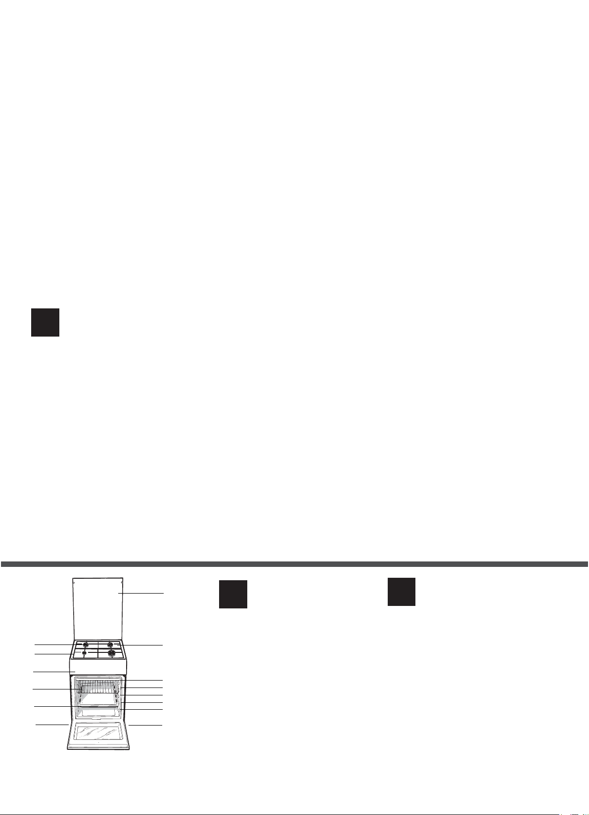
6
GB
1.Hob burner
2.Hob Grid
3.Control panel
4.Sliding grill rack
5.DRIPPING pan
6.Adjustable foot
7.Containment surface for spills
8.GUIDE RAILS for the sliding racks
9.position 5
10.position 4
11.position 3
12.position 2
13.position 1
14.Glass Cover
Overall view
UA
1.Газовий пальник
2.Піддон на випадок переливань
3.Панель управління
4.Полка РЕШІТKИ
5.Полка ДEКО
6.Лапка для налаштування
7.Пoверхня для збирання збiглoї piдини
8.HAПPABЛЯЮЧІ для полиць
9.положення 5
10.положення 4
11.положення 3
12.положення 2
13.положення 1
14. Скляна кришка
Опис плити
Загальнии вигляд
Page 3
5
5
2
314
2
364
78 9
5
1
2
3
4
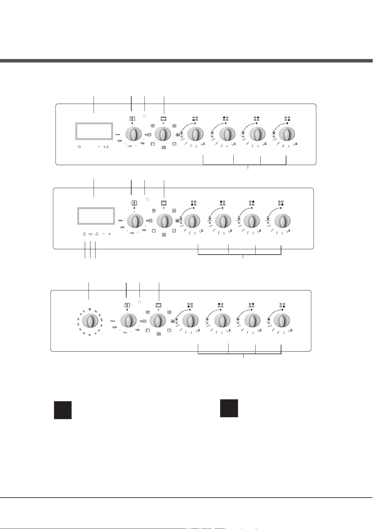
5
GB
1.TIMER knob
2.THERMOSTAT knob
3.THERMOSTAT indicator light
4.SELECTOR knob
5.Hob BURNER control knob
6.Electronic cooking programmer*
7.TIMER button
8.COOKING TIME button
9.COOKING END TIME button
Only available in certain models.
*
Description of the appliance
Control panel
UA
1.Сукоятка ТАЙМЕРА
2.Peґyлятор TEPMOCTATУ
3. Індикатор TEPMOCTATУ
4.Peґyлятор РСПГСБМ
5.Ручки для керування газовими
пальниками на варильній поверхні
6.ȿɥɟɤɬɪɨɧɧɢɣ ɩɪɨɝɪɚɦɚɬɨɪ ɩɪɢɝɨɬɭɜɚɧɧɹ ʀɠɿ
7.Ʉɧɨɩɤɚ ɌȺɃɆȿɊ
8.Ʉɧɨɩɤɚ ɌɊɂȼȺɅȱɋɌɖ ɉɊɂȽɈɌɍȼȺɇɇə
9.Ʉɧɨɩɤɚ ɁȺɄIɇɑȿɇɇə ɉɊɂȽɈɌɍȼȺɇɇə
Опис плити
Панель управління
*
3
Page 4
GB
Installation
! Before operating your new appliance please read
this instruction booklet carefully. It contains
important information concerning the safe installation
and operation of the appliance.
! Please keep these operating instructions for future
reference. Make sure that the instructions are kept
with the appliance if it is sold, given away or moved.
! The appliance must be installed by a qualified
professional according to the instructions provided.
! Any necessary adjustment or maintenance must be
performed after the cooker has been disconnected
from the electricity supply.
We recommend cleaning the oven before
using it for the first time, following the
instructions provided in the "Care and
maintenance" section.
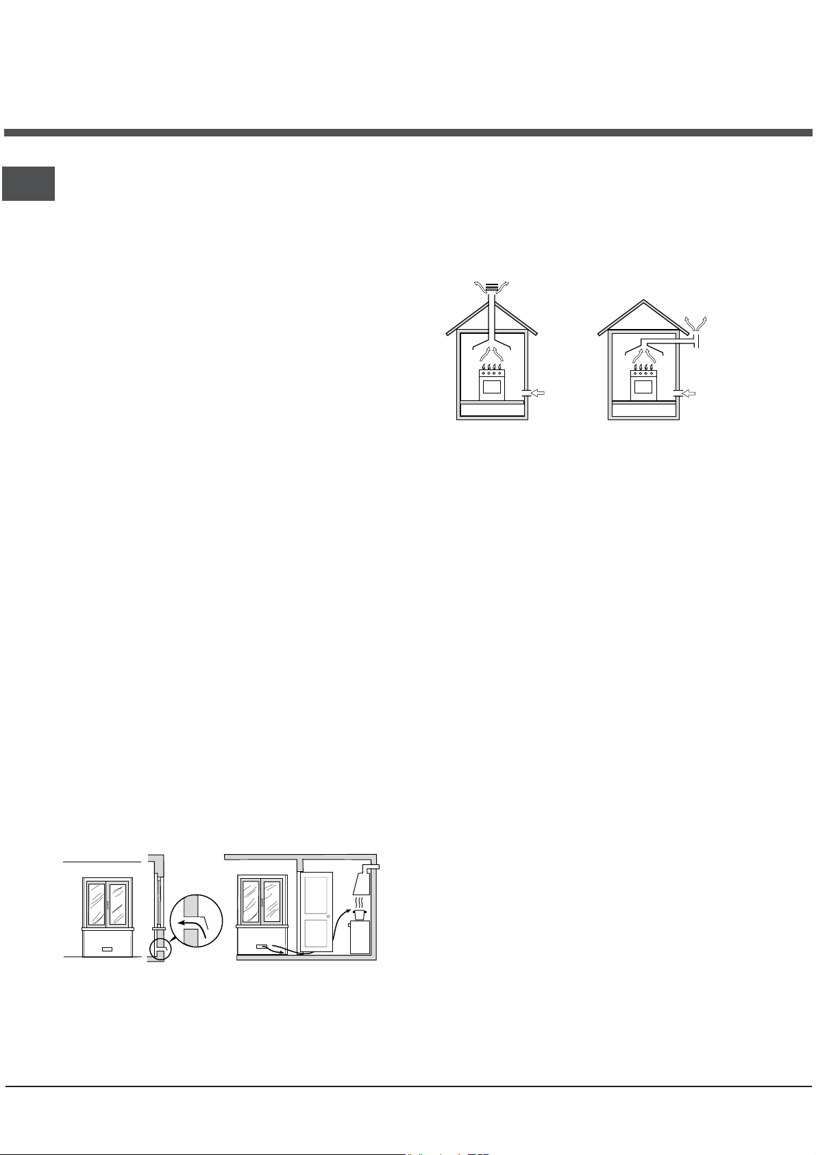
Room ventilation
The appliance may only be installed in permanentlyventilated rooms, according to current national
legislation. The room in which the appliance is
installed must be ventilated adequately so as to
provide as much air as is needed by the normal gas
combustion process (the flow of air must not be
lower than 2 m
The air inlets, protected by grilles, should have a
duct with an inner cross section of at least 100 cm
and should be positioned so that they are not liable
to even partial obstruction (
These inlets should be enlarged by 100% - with a
minimum of 200 cm2 - whenever the surface of the
hob is not equipped with a flame failure safety
device. When the flow of air is provided in an
indirect manner from adjacent rooms (
provided that these are not communal parts of a
building, areas with increased fire hazards or
bedrooms, the inlets should be fitted with a
ventilation duct leading outside as described above.
A
3
/h per kW of installed power).
see figure A
).
see figure B
Adjacent room Room requiring
B
ventilation
2
),
Disposing of combustion fumes
The disposal of combustion fumes should be
guaranteed using a hood connected to a safe and
efficient natural suction chimney, or using an electric
fan that begins to operate automatically every time
the appliance is switched on (
Fumes channelled
straight outside
! The liquefied petroleum gases are heavier than air
and collect by the floor, therefore all rooms
containing LPG cylinders must have openings
leading outside so that any leaked gas can escape
easily.
LPG cylinders, therefore, whether partially or
completely full, must not be installed or stored in
rooms or storage areas that are below ground level
(cellars, etc.). Only the cylinder being used should
be stored in the room; this should also be kept well
away from sources of heat (ovens, chimneys,
stoves) that may cause the temperature of the
cylinder to rise above 50°C.
see figure
Fumes channelled through a
chimney or a branched flue
system (reserved for cooking
appliances)
).
Positioning and levelling
! It is possible to install the appliance alongside
cupboards whose height does not exceed that of the
hob surface.
! Make sure that the wall in contact with the back of
the appliance is made from a non-flammable, heatresistant material (T 90°C).
A
Increase in the
gap between the door
and the flooring
! After prolonged use of the appliance, it is
advisable to open a window or increase the speed of
any fans used.
4
Ventilation opening
for comburent air
To install the appliance correctly:
• Place it in the kitchen, the dining room or the bedsit (not in the bathroom).
• If the top of the hob is higher than the cupboards,
the appliance must be installed at least 200 mm
away from them.
• If the cooker is installed underneath a wall cabinet,
there must be a minimum distance of 420 mm
between this cabinet and the top of the hob.
This distance should be increased to 700 mm if
the wall cabinets are flammable (
see figure
).
Page 5
• Do not position
blinds behind the
cooker or less than 200
mm away from its
sides.
mm. with hood
mm. without hood
• Any hoods must be
650
700
installed according to
min.
min.
mm.
420
Min.
HOOD
Min. mm.
600
420
Min. mm.
the instructions listed in
the relevant operating
manual.
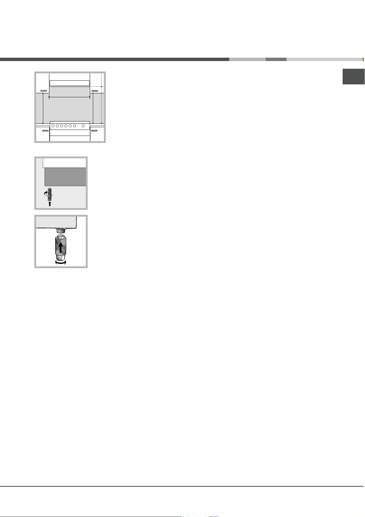
Levelling
If it is necessary to level the
appliance, screw the
adjustable feet into the places
provided on each corner of the
base of the cooker (
figure
).
see
The legs* fit into the slots on
the underside of the base of
the cooker.
Electrical connections
Install a standardised plug corresponding to the
load indicated on the appliance data plate (
Technical data table
).
The appliance must be directly connected to the mains
using an omnipolar circuit-breaker with a minimum
contact opening of 3 mm installed between the
appliance and the mains. The circuit-breaker must be
suitable for the charge indicated and must comply with
NFC 15-100 regulations (the earthing wire must not be
interrupted by the circuit-breaker). The supply cable
must be positioned so that it does not come into
contact with temperatures higher than 50°C at any point.
Before connecting the appliance to the power
supply, make sure that:
• The appliance is earthed and the plug is compliant
with the law.
• The socket can withstand the maximum power of
the appliance, which is indicated by the data plate.
• The voltage is in the range between the values
indicated on the data plate.
• The socket is compatible with the plug of the
appliance. If the socket is incompatible with the
plug, ask an authorised technician to replace it.
Do not use extension cords or multiple sockets.
* Only available in certain models
see
! Once the appliance has been installed, the power
supply cable and the electrical socket must be
easily accessible.
! The cable must not be bent or compressed.
! The cable must be checked regularly and replaced
by authorised technicians only.
! The manufacturer declines any liability should
these safety measures not be observed.
Gas connection
Connection to the gas network or to the gas cylinder
may be carried out using a flexible rubber or steel
hose, in accordance with current national legislation
and after making sure that the appliance is suited to
the type of gas with which it will be supplied (see
the rating sticker on the cover: if this is not the case
see below
install a pressure regulator which complies with
current national regulations. To make connection
easier, the gas supply may be turned sideways*:
reverse the position of the hose holder with that of
the cap and replace the gasket that is supplied with
the appliance.
! Check that the pressure of the gas supply is consistent
with the values indicated in the Table of burner and
nozzle specifications (
safe operation and durability of your appliance while
maintaining efficient energy consumption.
Gas connection using a flexible rubber hose
Make sure that the hose complies with current
national legislation. The internal diameter of the hose
must measure: 8 mm for liquid gas supply; 13 mm
for methane gas supply.
Once the connection has been performed, make
sure that the hose:
• Does not come into contact with any parts that
reach temperatures of over 50°C.
• Is not subject to any pulling or twisting forces and
that it is not kinked or bent.
• Does not come into contact with blades, sharp
corners or moving parts and that it is not
compressed.
• Is easy to inspect along its whole length so that
its condition may be checked.
• Is shorter than 1500 mm.
• Fits firmly into place at both ends, where it will be
fixed using clamps that comply with current
regulations.
). When using liquid gas from a cylinder,
see below
). This will ensure the
GB
5
Page 6
GB
! If one or more of these conditions is not fulfilled or
if the cooker must be installed according to the
conditions listed for class 2 - subclass 1 appliances
(installed between two cupboards), the flexible steel
hose must be used instead (
Connecting a flexible jointless stainless steel
pipe to a threaded attachment
Make sure that the hose and gaskets comply with
current national legislation.
To begin using the hose, remove the hose holder on
the appliance (the gas supply inlet on the appliance
is a cylindrical threaded 1/2 gas male attachment).
! Perform the connection in such a way that the hose
length does not exceed a maximum of 2 metres,
making sure that the hose is not compressed and
does not come into contact with moving parts.
Checking the connection for leaks
When the installation process is complete, check the
hose fittings for leaks using a soapy solution. Never
use a flame.
Safety Chain
see below
).
! In order
to prevent
accidental
tipping of the
appliance, for
example by
a child climbing onto the
oven door, the
supplied safety
chain MUST be
installed!
The cooker is fitted with a safety chain to be fixed by
means of a screw (not supplied with the cooker) to
the wall behind the appliance, at the same height as
the chain is attached to the appliance.
Choose the screw and the screw anchor according
to the type of material of the wall behind the appliance. If the head of the screw has a diameter smaller
than 9mm, a washer should be used. Concrete wall
requires the screw of at least 8mm of diameter, and
60mm of length.
Ensure that the chain is fixed to the rear wall of the
cooker and to the wall, as shown in figure, so that
after installation it is tensioned and parallel to the
ground level.
Adapting to different types of gas
It is possible to adapt the appliance to a type of gas
other than the default type (this is indicated on the
rating label on the cover).
Adapting the hob
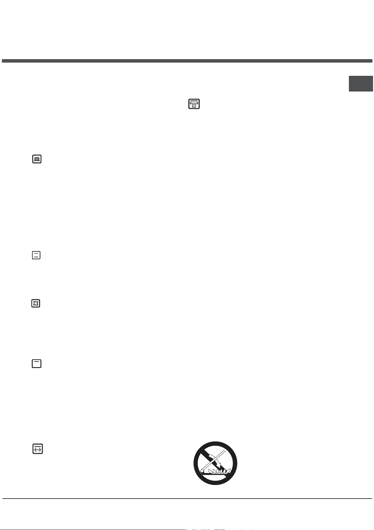
Replacing the nozzles for the hob burners:
1. Remove the hob grids and slide the burners off
their seats.
2. Unscrew the nozzles using
a 7 mm socket spanner (
figure
), and replace them with
nozzles suited to the new type
of gas (
specifications table
3. Replace all the components
by following the above instructions in reverse.
Adjusting the hob burners’ minimum setting:
1. Turn the tap to the minimum position.
2. Remove the knob and adjust the regulatory
screw, which is positioned inside or next to the tap
pin, until the flame is small but steady.
! If the appliance is connected to a liquid gas
supply, the regulatory screw must be fastened as
tightly as possible.
3. While the burner is alight, quickly change the position
of the knob from minimum to maximum and vice versa
several times, checking that the flame is not
extinguished.
! The hob burners do not require primary air adjustment.
! After adjusting the appliance so it may be used with a
different type of gas, replace the old rating label with a
new one that corresponds to the new type of gas (these
labels are available from Authorised Technical Assistance
Centres).
! Should the gas pressure used be different (or vary
slightly) from the recommended pressure, a suitable
pressure regulator must be fitted to the inlet hose in
accordance with current national regulations relating to
“regulators for channelled gas”.
see Burner and nozzle
see
).
6
Page 7
Table of burner and nozzle specifications
g
Table 1 Liquid Gas Natural Gas
Burner
Diameter
(mm)
Nominal Reduced (mm) (mm) *** ** (mm) (mm)
Fast
(Large)(R)
Semi Fast
(Medium)(S)
Auxiliary
(Small)(A)
100 3.00 0.7 41 87 218 214 128 286 145 286
75 1.90 0.4 30 69 138 136 104 181 115 181
51 1.00 0.4 30 50 73 71 78 95 85 95
Supply
Pressures
* At 15°C 1013 mbar-dry gas *** Butane P.C.S. = 49,47 MJ/Kg
** Propane P.C.S. = 50,37 MJ/K
S
S
R
A
H5G66AF UA
H5G65AE C UA
H5G62AE UA
Thermal Power
kW (p.c.s.*)
Nominal (mbar)
Minimum (mbar)
Maximum (mbar)
By Pass
1/100
Nozzle
1/100
Flow*
g/h
28-30
20
35
Natural P.C.S. = 37,78 MJ/m³
TECHNICAL DATA
Oven dimensions
(HxWxD)
Volume
Useful
measurements
relating to the
oven
compartment
Power supply
voltage and
frequency
Burners
ENERGY LABEL
Nozzle
1/100
37
25
45
Flow*
l/h
20
17
25
width 410 mm
height 340 mm
depth 424 mm
60 l
width 42 cm
depth 44 cm
height 17 cm
see data plate
may be adapted for use with any
type of gas shown on the data
plate, which is located inside the
flap or, after the oven compartment
has been opened, on the left-hand
wall inside the oven.
Directive 2002/40/EC on the label
of electric ovens. Standard EN
50304
Energy consumption for Natural
convection – heating mode:
Static
Declared energy consumption for
Forced convection Class – heating
mode: Baking
Nozzle
1/100
GB
Flow*
l/h
13
6,5
18
EC Directives: 2006/95/EC dated
12/12/06 (Low Voltage) and
subsequent amendments –
2004/108/EC dated 15/12/04
(Electromagnetic Compatibility) and
subsequent amendments 2009/142/EC dated 30/22/09 (Gas)
and subsequent amendments 93/68/EEC dated 22/07/93 and
subsequent amendments 2002/96/EC.
1275/2008 (Stand-by/ Off mode)
7
Page 8
Start-up and use
GB
Using the hob
Lighting the burners
For each BURNER knob there is a complete ring
showing the strength of the flame for the relevant
burner.
To light one of the burners on the hob:
1. Bring a flame or gas lighter close to the burner.
2. Press the BURNER knob and turn it in an
anticlockwise direction so that it is pointing to the
maximum flame setting E.
3. Adjust the intensity of the flame to the desired
level by turning the BURNER knob in an
anticlockwise direction. This may be the minimum
setting C, the maximum setting E or any position
in between the two.
If the appliance is fitted with
an electronic lighting
X
.
may be extinguished when the knob is released. If
this occurs, repeat the operation, holding the knob
down for a longer period of time.
! If the flame is accidentally extinguished, switch
off the burner and wait for at least 1 minute before
attempting to relight it.
If the appliance is equipped with a flame failure
safety device*, press and hold the BURNER knob
for approximately 2-3 seconds to keep the flame
alight and to activate the device.
To switch the burner off, turn the knob until it
reaches the stop position XXX.
Flame adjustment according to levels
the burner flame intensity can be adjusted with the
knob according to 6 power levels, from maximum
to minimum with 4 intermediate positions:
a click will indicate the change from one level to
another when turning the knob . The system
guarantees a more precise adjustment, allows
to replicate the flame intensity and to identify
easily the preferred level for different cooking
operations.
Practical advice on using the burners
For the burners to work in the most efficient way
possible and to save on the amount of gas
consumed, it is recommended that only pans that
have a lid and a flat base are used. They should
also be suited to the size of the burner.
To identify the type of burner, please refer to the
diagrams contained in the “Burner and nozzle
specifications”.
device* (
the BURNER knob and turn
it in an anticlockwise
direction, towards the
minimum flame setting, until
C
the burner is lit. The burner
C),
press
Burner ø Cookware diameter (cm)
Fast (R) 24 - 26
Semi Fast (S) 16 - 20
Auxiliary (A) 10 - 14
Using the oven
! The first time you use your appliance, heat the
empty oven with its door closed at its maximum
temperature for at least half an hour. Ensure that the
room is well ventilated before switching the oven off
and opening the oven door. The appliance may emit
a slightly unpleasant odour caused by protective
substances used during the manufacturing process
burning away.
! Before operating the product, remove all plastic film
from the sides of the appliance.
1. Select the desired cooking mode by turning the
SELECTOR knob.
2. Select the recommended temperature for the
cooking mode or the desired temperature by turning
the THERMOSTAT knob.
A list detailing cooking modes and suggested
cooking temperatures can be found in the relevant
table (
see Oven cooking advice table
During cooking it is always possible to:
• Change the cooking mode by turning the
SELECTOR knob.
• Change the temperature by turning the
THERMOSTAT knob.
• Set the total cooking time and the cooking end
time (
see below
• Stop cooking by turning the SELECTOR knob to
the “0” position.
! Never put objects directly on the bottom of the
oven; this will avoid the enamel coating being
damaged. Only use position 1 in the oven when
cooking with the rotisserie spit.
! Always place cookware on the rack(s) provided.
THERMOSTAT indicator light
When this is illuminated, the oven is generating
heat. It switches off when the inside of the oven
reaches the selected temperature. At this point the
light illuminates and switches off alternately,
indicating that the thermostat is working and is
maintaining the temperature at a constant level.
Oven light
This is switched on by turning the SELECTOR knob
to any position other than “0”. It remains lit as long
as the oven is operating. By selecting
knob, the light is switched on without any of the
heating elements being activated.
Only available in certain models.
*
).
).
88
8
88
with the
8
Page 9
Cooking modes
! A temperature value can be set for all cooking
modes between 50°C and MAX, except for the
following modes:
• GRILL and DOUBLE GRILL (recommended: set
only to MAX power level).
• FAN-ASSISTED DOUBLE GRILL (recommended:
do not exceed 200°C).
BAKING mode
Temperature: any temperature between 50°C and Max.
The rear heating element and the fan come on,
guaranteeing delicate heat distributed uniformly
throughout the oven.
This mode is ideal for baking and cooking delicate
foods - especially cakes that need to rise - and for the
preparation of certain tartlets on 3 shelves at the same
time. Here are a few examples: cream puffs, sweet and
savoury biscuits, savoury puffs, Swiss rolls and small
portions of vegetables au gratin, etc…..
STATIC OVEN mode
Both the top and bottom heating elements will be
activated. When using this traditional cooking mode,
it is best to use only one rack at a time, otherwise
the heat will not be distributed evenly.
FAN OVEN FAN OVEN
FAN OVEN mode
FAN OVEN FAN OVEN
The top and bottom heating elements will switch on
and the fan will begin to operate. Since the heat
remains constant throughout the oven, the air cooks
and browns food in a uniform manner. A maximum
of two racks may be used at the same time.
cooking efficiency by 50% and eliminates the cooler
corner areas. Use this grilling mode to achieve a
uniform browning on top of the food.
DOUBLE GRILL mode
The top heating element and the turnspit are
activated and the fan begins to operate. This
combination of features increases the effectiveness
of the unidirectional thermal radiation of the heating
elements through forced circulation of the air
throughout the oven. This prevents the food from
burning on top by enabling heat to penetrate into the
food more effectively; it is therefore an ideal way of
cooking food quickly under the grill or for grilling large
pieces of meat without having to use the turnspit.
! The GRILL, DOUBLE GRILL and FAN-ASSISTED
DOUBLE GRILL cooking modes must be performed
with the oven door shut.
! When using the GRILL and DOUBLE GRILL
cooking modes, place the rack in position 5 and the
dripping pan in position 1 to collect cooking
residues (fat and/or grease). When using the FANASSISTED DOUBLE GRILL cooking mode, place the
rack in position 2 or 3 and the dripping pan in
position 1 to collect cooking residues.
Electronic timer
This function displays the time and works as a timer
which counts down to zero.
! All functions will be implemented approximately 7
seconds after they have been set.
Resetting the clock
GB
mode
GRILL
The central part of the top heating element is
switched on. The high and direct temperature of the
grill is recommended for food that requires a high
surface temperature (veal and beef steaks, fillet
steak and entrecôte). This cooking mode uses a
limited amount of energy and is ideal for grilling
small dishes. Place the food in the centre of the
rack, as it will not be cooked properly if it is placed
in the corners.
DOUBLE GRILL
The top heating element and the turnspit will be
activated.
This provides a larger grill than the normal grill
setting and has an innovative design that improves
mode
After the appliance has been connected to the
power supply, or after a power cut, the clock display
will begin to blink, showing the figure:
• Press button
the exact time. Press and hold the buttons to
quicken the count upwards.
repeating the above process.
G G
and then buttons - and + to set
G
G G
WARNING! The glass lid canWARNING! The glass lid can
WARNING! The glass lid can
WARNING! The glass lid canWARNING! The glass lid can
break in if it is heated up. Turnbreak in if it is heated up. Turn
break in if it is heated up. Turn
break in if it is heated up. Turnbreak in if it is heated up. Turn
off all the burners and theoff all the burners and the
off all the burners and the
off all the burners and theoff all the burners and the
electric plates before closingelectric plates before closing
electric plates before closing
electric plates before closingelectric plates before closing
the lid. *Applies to the modelsthe lid. *Applies to the models
the lid. *Applies to the models
the lid. *Applies to the modelsthe lid. *Applies to the models
with glass cover only.with glass cover only.
with glass cover only.
with glass cover only.with glass cover only.
0:000:00
0:00
0:000:00
9
Page 10

GB
Timer feature
GG
G
GG
nn
n
nn
see
This function may be accessed by pressing the
button, after which the display will show the symbol
nn
n
. Every time the + button is pressed it
nn
corresponds to a time increase of 10 seconds, until
it reaches 99 minutes and 50 seconds. After this
point, each press of the button represents an
increase of one minute, up to a maximum of 10 hours.
Pressing the
After the time period has been set, the timer will
begin to count down. When the timer reaches zero,
the buzzer will sound (this may be stopped by
pressing any button).
The time may be displayed by pressing the
button, and the
function has been set. After approximately 7 seconds,
the display will automatically revert to the timer.
Cancelling a time that has already been set
Press the - button until the display shows
Adjusting the buzzer volume
After selecting and confirming the clock settings,
use the - button to adjust the volume of the alarm
buzzer.
Rotisserie
3. Activate the rotisserie by selecting
the SELECTOR knob.
Lower compartment*
! The internal surfaces of the compartment (where
present) may become hot.
! Do not place flammable materials in the lower oven
compartment.
button reduces the time.
-
nn
n symbol indicates that the timer
nn
To activate the
rotisserie function (
diagram
follows:
1. Place the dripping
pan in position 1.
2. Place the rotisserie
support in position 4
and insert the spit in the
hole provided on the
back panel of the oven.
There is a compartment
underneath the oven
that may be used to
store oven accessories
or deep dishes. To
open the door pull it
downwards (
figure
) proceed as
or with
see
).
0:00.0:00.
0:00.
0:00.0:00.
Timer Knob*
Some models are equipped with a timer program to
control when the oven shuts off during cooking. To use
this feature, you must wind the knob one full turn in the
counter-clockwise direction
the clockwise direction
up the indicator on the control panel with the number
of minutes on the knob. At the end of the programmed
length of time, the timer will sound and automatically
turn off the oven.
!: to use the oven in manual mode without the cooking
control timer, match the indicator on the control panel
with the
is not in use, the cooking control timer can be used like
a normal timer.
symbol on the timer knob. When the oven
; Then, turn the knob in
, to set the time by matching
! Avoid the children touch the oven door because it is
very hot during the cooking.
Cooking on several shelves simultaneously
If it is necessary to use two racks, use the FAN
OVEN cooking mode
mode suited to this type of cooking. We also
recommend that:
• Positions 1 and 5 are not used. This is because
excessive direct heat can burn temperature
sensitive foods.
• Positions 2 and 4 are used and that food that
requires more heat is placed on the rack in
position 2.
• When cooking foods that require different cooking
times and temperatures, set a temperature that is
halfway between the two recommended
temperatures (
and place the more delicate food on the rack in
position 4. Remove the food that requires a
shorter cooking time first.
• When cooking pizzas on several racks with the
temperature set to 220°C, the oven is preheated
for 15 minutes. Generally speaking, cooking on
the rack in position 4 takes longer: we
recommend that the pizza cooked on the lowest
rack position is removed first, followed by the
pizza cooked in position 4 a few minutes later.
• Place the dripping pan on the bottom and the rack
on top.
* Only available in certain models.
see Oven cooking advice table
, as this is the only cooking
bb
b
bb
)
10
Page 11

Planning cooking with the electronic
programmer
Setting the clock
After the appliance has been connected to the
power supply, or after a blackout, the display will
automatically reset to 0:00 and begin to blink. To set
the time:
1. Press the COOKING TIME button
simultaneously.
COOKING END TIME
2. Within 4 seconds of having pressed these buttons,
set the exact time by pressing the
button advances the hours and the button
The
decreases the hours.
Once the time has been set, the programmer
automatically switches to manual mode.
Setting the timer
The timer enables a countdown to be set, when the
time has elapsed a buzzer sounds.
To set the timer proceed as follows:
1. press the TIMER button
+
. The display shows:
and the
and buttons.
1.
2. Press the and buttons to set the desired time.
3. When the buttons are released the timer begins
counting down and the current time appears on the
display.
5
4. After the time has elapsed a buzzer will sound, and
this can be switched off by pressing any button (except
and buttons). The symbol +will switch off.
the
Adjusting the volume of the buzzer
After selecting and confirming the clock settings, use
button to adjust the volume of the alarm buzzer.
the
Setting the cooking time with a delayed start
First decide which cooking mode you wish to use and
set a suitable temperature using the SELECTOR and
! The timer does not switch the oven on or off.
THERMOSTAT knobs on the oven.
At this point it is possible to set the cooking time:
1. Press the COOKING TIME button
2. Within 4 seconds of having pressed this button, set
the desired amount of time by pressing the
buttons. If, for example, you wish to set a cooking time
of 30 minutes, the display will show:
.
and
1
3. 4 seconds after the buttons are released, the current
time (for example 10.00) reappears on the display with
and the letter A (AUTO).
the symbol
Next the desired cooking end time must be set:
4. Press the END COOKING TIME button
5. Within 4 seconds of having pressed this button,
adjust the cooking end time by pressing the
buttons. If, for example, you want cooking to end at
13.00, the display shows:
P
.
and
2
6. 4 seconds after the buttons are released, the current
time (for example 10.00) reappears on the display with
the letter A (AUTO).
3
At this point, the oven is programmed to switch on
automatically at 12:30 and switch off after 30 minutes,
at 13.00.
Setting the cooking time with an immediate start
Follow the above procedure for setting the cooking
time (points 1-3).
! When the letter A appears, this indicates that both
the cooking time and the end cooking time have been
programmed in AUTO mode. To restore the oven to
manual operation, after each AUTO cooking mode
press the COOKING TIME
buttons simultaneously.
TIME
P
! The symbol
the entire duration of the cooking programme.
The set cooking duration can be displayed at any time
by pressing the COOKING TIME button
the cooking end time may be displayed by pressing
the END COOKING TIME button
time has elapsed a buzzer sounds. To stop it, press
any button apart from the
Cancelling a previously set cooking programme
Press the COOKING TIME button
COOKING END TIME
Correcting or cancelling previously set data
The data entered can be changed at any time by
pressing the corresponding button (TIMER, COOKING
will remain lit, along with the oven, for
and END COOKING
. When the cooking
and buttons.
and the
simultaneously.
!
, and
TIME or COOKING END TIME) and the
When the cooking time data is cancelled, the cooking
end time data is also cancelled automatically, and vice
versa.
If the oven has already been programmed, it will not
accept cooking end times which are before the start of
the programmed cooking process.
or button.
GB
11
Page 12

GB
Oven cooking advice table
Cooking
modes Foods
Weight
(in kg)
Rack
position
Preheating time
(min)
Recommended
Temperature
(°C)
Cooking
time
(minutes)
Baking
Static
Fan-assisted
Grill
Double Grill
Fan-assisted
Double Grill
Tarts
Fruit cakes
Plum cake
Sponge cake
Stuffed pancakes (on 2
racks)
Small cakes (on 2 racks)
Cheese puffs (on 2
racks)
Cream puffs (on 3 racks)
Biscuits (on 3 racks)
Duck
Roast veal or beef
Roast pork
Biscuits (shortcrust pastry)
Tarts
Pizza (on 2 racks)
Lasagne
Lamb
Roast chicken + potatoes
Mackerel
Sponge cake made with yoghurt
Cream puffs (on 2 racks)
Biscuits (on 2 racks)
Sponge cake (on 1 rack)
Sponge cake (on 2 racks)
Savoury pies
Sole and cuttlefish
Squid and prawn kebabs
Cod fillet
Grilled vegetables
Veal steak
Cutlets
Hamburgers
Mackerel
Toast
With the rotisserie
Spit-roast veal
Spit-roast chicken
Spit-roast lamb
Grilled chicken
Cuttlefish
Chicken (on the spit) +
potatoes (on the dripping pan)
With the rotisserie
Spit-roast veal
Spit-roast chicken
Spit-roast lamb
With multi-spit rotisserie (where present)
Meat kebabs
Vegetable kebabs
0.5
1
0.7
0.5
1.2
0.6
0.4
0.7
0.7
0.5
1+1
0.5
0.5
0.5
1.5
4 pcs
1.0
1.5
1.0
1.5
1.5
1.5
1.5
1.5
1.5
1.0
0.8
3
2/3
3
3
2-4
2-4
2-4
1-3-5
1-3-5
1-3-5
1
1
1
1
1
1
1
1
1
1
1
1
1
1
1
1
1
1
-
3
3
3
3
3
2 and 4
3
2
2 and 4
2
2
2 and 4
2 and 4
2
2 and 4
3
4
4
4
3/4
4
4
4
4
4
-
-
-
2
2
-
2
-
-
-
-
-
15
15
15
15
15
15
15
15
15
15
15
15
15
15
15
15
10
10
15
10
10
10
10
10
10
15
5
5
5
5
5
5
5
5
5
5
5
5
5
5
5
5
5
5
5
5
5
180
180
180
160
200
190
210
180
180
90
200
200
200
180
180
230
180
180
200
180
170
190
180
170
170
200
Max
Max
Max
Max
Max
Max
Max
Max
Max
Max
Max
Max
200
200
200
200
200
200
200
200
200
20-30
40-45
40-50
25-30
30-35
20-25
15-20
20-25
20-25
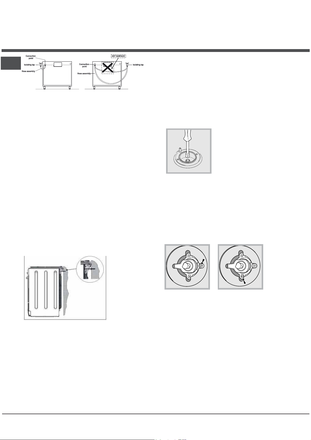
180
65-75
70-75
70-80
15-20
30-35
15-20
30-35
40-45
60-70
30-35
40-50
20-25
10-15
15-20
20-25
25-30
8-10
6-8
10
10-15
15-20
15-20
7-10
15-20
2-3
80-90
70-80
70-80
55-60
30-35
70-75
70-75
70-80
70-80
70-80
40-45
25-30
12
Page 13

Precautions and tips
! This appliance has been designed and manufactured
in compliance with international safety standards.
The following warnings are provided for safety reasons
and must be read carefully.
General safety
• These instructions are only valid for the countries
whose symbols appear in the manual and on the
serial number plate.
• The appliance was designed for domestic use inside
the home and is not intended for commercial or
industrial use.
• The appliance must not be installed outdoors, even
in covered areas. It is extremely dangerous to leave
the appliance exposed to rain and storms.
• Do not touch the appliance with bare feet or with wet
or damp hands and feet.
• The appliance must be used by adults only for
the preparation of food, in accordance with the
instructions outlined in this booklet. Any other
use of the appliance (e.g. for heating the room)
constitutes improper use and is dangerous. The
manufacturer may not be held liable for any
damage resulting from improper, incorrect and
unreasonable use of the appliance.
• The instruction booklet accompanies a class 1
(insulated) or class 2 - subclass 1 (recessed
between 2 cupboards) appliance.
• Keep children away from the oven.
• Make sure that the power supply cables of other
electrical appliances do not come into contact with
the hot parts of the oven.
• The openings used for the ventilation and dispersion
of heat must never be covered.
• Do not close the glass hob cover (selected models
only) when the burners are alight or when they are
still hot.
• Always use oven gloves when placing cookware in
the oven or when removing it.
• Do not use flammable liquids (alcohol, petrol, etc...)
near the appliance while it is in use.
• Do not place flammable material in the lower storage
compartment or in the oven itself. If the appliance is
switched on accidentally, it could catch fire.
• Always make sure the knobs are in the • position
and that the gas tap is closed when the appliance is
not in use.
• When unplugging the appliance, always pull the
plug from the mains socket; do not pull on the cable.
• Never perform any cleaning or maintenance work
without having disconnected the appliance from the
electricity mains.
• If the appliance breaks down, under no
circumstances should you attempt to repair the
appliance yourself. Repairs carried out by
inexperienced persons may cause injury or further
malfunctioning of the appliance. Contact Assistance.
• Do not rest heavy objects on the open oven door.
• Do not let children play with the appliance.
• The appliance should not be operated by people
(including children) with reduced physical, sensory or
mental capacities, by inexperienced individuals or by
anyone who is not familiar with the product. These
individuals should, at the very least, be supervised by
someone who assumes responsibility for their safety or
receive preliminary instructions relating to the operation
of the appliance.
Disposal
• When disposing of packaging material: observe local
legislation so that the packaging may be reused.
• The European Directive 2002/96/EC relating to Waste
Electrical and Electronic Equipment (WEEE) states that
household appliances should not be disposed of using
the normal solid urban waste cycle. Exhausted
appliances should be collected separately in order to
optimise the cost of re-using and recycling the
materials inside the machine, while preventing potential
damage to the atmosphere and to public health. The
crossed-out dustbin is marked on all products to
remind the owner of their obligations regarding
separated waste collection.
Exhausted appliances may be collected by the public
waste collection service, taken to suitable collection
areas in the area or, if permitted by current national
legislation, they may be returned to the dealers as part
of an exchange deal for a new equivalent product.
All major manufacturers of household appliances
participate in the creation and organisation of systems
for the collection and disposal of old and disused
appliances.
Respecting and conserving the environment
• You can help to reduce the peak load of the electricity
supply network companies by using the oven in the
hours between late afternoon and the early hours of the
morning.
• Always keep the oven door closed when using the
GRILL, DOUBLE GRILL and FAN-ASSISTED DOUBLE
GRILL modes: This will achieve better results while
saving energy (approximately 10%).
• Check the door seals regularly and wipe them clean to
ensure they are free of debris so that they adhere
properly to the door, thus avoiding heat dispersion.
GB
13
Page 14
Care and maintenance
Switching the appliance off
Disconnect your appliance from the electricity supply
before carrying out any work on it.
Cleaning the appliance
! Do not use abrasive or corrosive detergents such as
stain removers, anti-rust products, powder detergents or
sponges with abrasive surfaces: these may scratch the
surface beyond repair.
! Never use steam cleaners or pressure cleaners on the
appliance.
• It is usually sufficient simply to wash the hob using a
damp sponge and dry it with absorbent kitchen roll.
• The stainless steel or enamel-coated external parts and
the rubber seals may be cleaned using a sponge that
has been soaked in lukewarm water and neutral soap.
Use specialised products for the removal of stubborn
stains. After cleaning, rinse well and dry thoroughly. Do
not use abrasive powders or corrosive substances.
• The hob grids, burner caps, flame spreader rings and
burners may be removed to make cleaning easier;
wash them in hot water and non-abrasive detergent,
making sure all burnt-on residue is removed before
drying them thoroughly.
The cover
If the cooker is fitted with a cover,
this cover should be cleaned using
lukewarm water. Do not use
abrasive products.
It is possible to remove the cover in
order to make cleaning the area
behind the hob easier. Open the
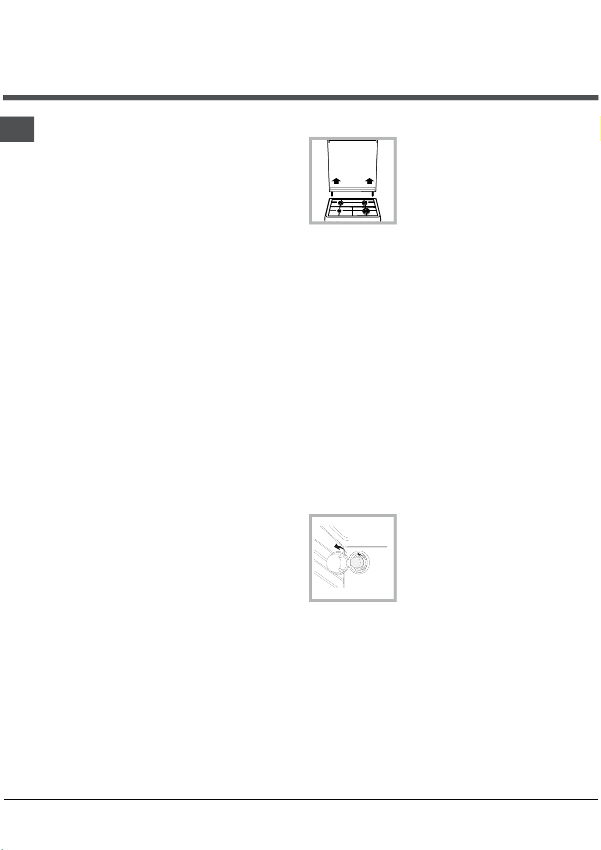
cover fully and pull it upwards (
figure
).
! Do not close the cover when the burners are alight or
when they are still hot.
Inspecting the oven seals
Check the door seals around the oven regularly. If the
seals are damaged, please contact your nearest
Authorised After-sales Service Centre. We recommend
that the oven is not used until the seals have been
replaced.
Gas tap maintenance
Over time, the taps may become jammed or difficult to
turn. If this occurs, the tap must be replaced.
! This procedure must be performed by a qualified
technician who has been authorised by the
manufacturer.
see
• For hobs with electronic ignition, the terminal part of the
electronic lighting devices should be cleaned
frequently and the gas outlet holes should be checked
for blockages.
• The inside of the oven should ideally be cleaned after
each use, while it is still lukewarm. Use hot water and
detergent, then rinse well and dry with a soft cloth. Do
not use abrasive products.
•
Clean the glass part of the oven door using a sponge
and a non-abrasive cleaning product, then dry
thoroughly with a soft cloth. Do not use rough abrasive
material or sharp metal scrapers as these could
scratch the surface and cause the glass to crack.
• The accessories can be washed like everyday
crockery, and are even dishwasher safe.
• Stainless steel can be marked by hard water that has
been left on the surface for a long time, or by
aggressive detergents containing phosphorus. After
cleaning, rinse well and dry thoroughly. Any remaining
drops of water should also be dried.
Replacing the oven light bulb
1. After disconnecting the oven
from the electricity mains, remove
the glass lid covering the lamp
socket (
2. Remove the light bulb and
replace it with a similar one:
voltage 230 V, wattage 25 W,
cap E 14.
3. Replace the lid and reconnect
the oven to the electricity supply.
see figure
).
Assistance
Please have the following information to hand:
• The appliance model (Mod.).
• The serial number (S/N).
This information can be found on the data plate located on
the appliance and/or on the packaging.
14
Page 15

Removing and fitting the oven door:
1.Open the door
2.Make the hinge clamps of the oven door rotate
backwards completely (see photo)
3.Close the door until the clamps stop (the door will
remain open for 40° approx.) (see photo)
40°
WARNING! When reassembling the inner door
glass insert the glass panel correctly so that the
text written on the panel is not reversed and
can be easily legible.
7.Replace the profile, a click will indicate that the
part is positioned correctly.
8.Open the door completely.
9.Close the supports (see photo).
10.Now the door can be completely closed and the
oven can be started for normal use.
GB
4.Press the two buttons on the upper profile and
extract the profile (see photo)
5.Remove the glass sheet and do the cleaning as
indicated in chapter: "Care and maintenance".
6.Replace the glass.
WARNING! Oven must not be operated with inner
door glass removed!
15
Page 16

Встановленн
UA
! Важливо зберегти цю брошуру, щоб можна було
до неі звернутися при необхідності у будь-якому
випадку. У разі продажу, передачi iншiи особi
або переізду, переконаитеся в тому, що вона
залишається разом з виробом.
! Уважно прочитаите інструкціі: інформація про
обладнання, використання и безпеку грає дуже
важливу роль.
! Установка вироба
має виконуватися згідно даноі
інструкціі кваліфікованим персоналом.
! Будь-яке втручання в регулювання або технічне
обслуговування має виконуватися на плиті,
відключеніи від електроживлення.
Вентиляція приміщень
Обладнання може бути встановлене тільки у
постіино вентильованих приміщеннях, згідно діючим
нормам в краінi, де вироб буде викорисовано. У
приміщенні, в якому встановлено обладнання, має
відбуватися зміна
повітря, у ступені, необхідному
для нормального горіння газу (швидкість зміни
3
повітря не має бути меншою 2м
/год на кожнии кВт
встановленоі потужності).
Вхід приточноі вентиляціі, захищении ґраткою, повинен
2
мати корисну площу не менше 100 см
корисного
перетину і має бути розміщении так, щоб він не міг
забитися, навіть частково ( див. малюнок A).
Такии вхід повинен бути збільшении на 100%, тобто
2
мінімум 200 см
– якщо робоча поверхня плити не
має пристрою безпеки у разі зникнення полум’я, і
коли можливии непрямии потік повітря із прилеглих
приміщень (див.малюнок B) – якщо це не спільні
частини будівлі, пожежонебезпечне приміщення
або спальні кімнати, обладнані вентиляціиним
трубопроводом назовні, як описано вище.
A
B
Прилеглі
приміщення
Вентильовані
приміщення
A
Вентиляціинии отвір для
відпрацьованого повітря
Збільшення щілини між
дверима і підлогою
! Після тривалого використання плити, доцільно
відкрити
вікно або збільшити швидкість вентиляторів.
Відведення продуктів згорання
Відведення продуктів згорання має бути
забезпечене через витяжку, підключену до каналу з
природною тягою з належною ефективністю, або за
допомогою електровентилятора, якии би включався
автоматично кожного разу при включенні плити (див
малюнки).
Відведення
безпосередньо
назовні
Відведення через канал або
розгалужении димар
(зарезервовании для
кухонного устаткування)
! Зріджені нафтові гази, важчі за повітря, бираються
внизу, тому приміщення, де
знаходяться балони з
газом, повинні бути обладнані витяжними отворами,
що виходять назовні для евакуаціі знизу при
можливому витоку газу.
Балони із зрідженим нафтовим газом, порожні або
частково повні, не повинні бути встановлені або
берігатися в приміщеннях нижче за рівень грунту
(льохи і т.п.). У приміщенні можна тримати тільки
використовувании
балон, далеко від джерел тепла
(печі, каміни, обігрівачі), які нагріваються вище від
50°C.
Розміщення і вирівнювання
! Можна встановлювати плиту збоку від меблів, які
не вищі за робочу поверхню.
! Переконаитеся в тому, що поверхня стіни, яка
контактує із задньою частиною плити, виготовлена
з негорючого та теплостіикого матеріалу і витримує
нагрівання (90°C).
Для правильного встановлення
• розміщуите плиту в кухні, обідніи залі або в
однокімнатніи квартирі-студіі (не у
• якщо поверхня плити є трохи вищою, ніж
поверхня меблів, меблі повинні знаходитися не
ближче ніж 200 мм від плити;
• якщо плита буде встановлена під секцією навісних
меблів, esso відстань до іі поверхні не повинна
бути меншою за 420 мм.
Така відстань повинна складати 700 мм, якщо
секція навісних меблів зроблена з горючого
матеріалу (див. малюнок);
• не розміщуите занавісок позаду плити або ближче
ніж 200 мм від іі сторін;
ванні);
16
Page 17

HOOD
420
Min.
min.
650
mm. with hood
min.
700
mm. without hood
mm.
600
Min. mm.
420
Min. mm.
• витяжки повинні
встановлюватися згідно
вказівкам відповідноі
інструкціі.
Вирівнювання
Якщо необхідно
вирівняти плиту,
вкрутіть регулюючі
ніжки, що входять до комплекту постачання,
у спеціальні місця, що
знаходяться у кутках основи
(див. малюнок).
Ніжки* вмонтовуються у гнізда
під основою плити.
Підключення
електроенергіі
Встановіть на кабелі
вилку, розраховану на
навантаження, вказане на табличці з технічними
характеристиками, розміщеніи на плиті (див.
таблицю Технічних Даних).
У разі прямого підключення до мережі необхідно
помістити між плитою і мережею всеполярнии
вимикач з мінімальною відстанню між контактами 3
мм, розраховании на вказане навантаження і такии,
що відповідає нормі NFC 15-100 (дріт заземлення
повинен перериватися вимикачем). Кабель живлення
повинен бути розташовании так, щоб жодна з иого
частин не піддавалася нагріванню вище, ніж на 50°C
від температури довкілля.
До виконання підключення переконаитеся, що:
• розетка має заземлення, відповідно до встановлених
норм;
• розетка витримує максимальне навантаження
потужності обладнання, вказане на табличці з
характеристиками;
• напруга живлення
вказаних на табличці;
• розетка сумісна з вилкою плити. В іншому випадку
замініть розетку або вилку; не використовуите
подовжувачі и тріиники.
! У встановленіи плиті, має бути забезпечении
легкии доступ до електричного кабелю і розетки.
* Є лише в деяких моделях.
знаходиться в межах значень,
не
! Кабель не повинен мати перегинів або бути
стиснутим.
! Кабель має періодично перевірятися і мінятися
тільки фахівцями.
! Підприємство не несе будь-якоі
відповідальності, якщо ці норми не
дотримуватимуться.
Підключення газу
Підключення до газовоі мережі або балона може
виконуватися за допомогою гнучкого гумового шланга
або шланга в сталевому обплетенні, згідно діючим
національним нормам і після того, як встановлено,
що плита була налаштована на тип газу, на якому
вона працюватиме (див. Калібрувальна бирка на
кришці: в іншому випадку див. нижче). У разі
плити від балона із зрідженим газом, використовуите
редуктори відповідно до діючих норм у странi,
де буде використовано вироб. Щоб полегшити
підключення, живлення газу може подаватися
збоку *: переставте в обратному напрямi утримувач
гумки для підключення замикаючоі пробки і замініть
ущільнювач, що входить у комплект постачання.
! Для безперебіиноі роботи, для
адекватного
використання енергіі і для більшого терміну служби
плити, забезпечте тиск подачі газу в межах значень,
вказаних в таблиці Характеристик пальників і
форсунок (див. нижче).
Підключення газу за допомогою гнучкого
гумового шланга
Перевірте, щоб шланг відповідав діючим державним
нормам. Внутрішніи діаметр шланга повинен бути: 8
мм для зрідженого газу; 13 мм для метану.
Виконавши з’єднання, переконаитеся в тому, що
шланг:
• не торкається частин, які нагріваються вище
температури в 50оC;
• не має будь-якого натягнення або скручування, не
має згинів або стискань;
• не торкається гострих предметів, краів, рухомих
частин і не здавлении;
• може бути легко оглянутии по всіи довжині для
контролю иого
стану;
• має довжину меншу ніж 1500 мм;
• добре закріплении на обох кінцях за допомогою
хомутів, відповідно до діючих державних норм.
Точк а
кріплення
Відсічний
кран
Блок гнучки
труб
Точк а
кріплення
Блок гнучки
труб
ГАРЯЧА ПОВЕРХНЯ
роботи
Відсічний
кран
UA
17
Page 18

UA
! Якщо одна або більше з цих умов не будуть
дотримані, або якщо плита встановлена згідно
умовам класу 2 - підклас 1 (плита, встановлена між
двома шафами), необхідно використовувати гнучкии
! У разі зріджених газів, регулювальнии гвинт
повинен бути вкручении до упору;
3. перевірте, щоб при швидкому обертанні крана з
максимального в мінімальне положення, пальник не
гаснув.
шланг в сталевому обплетенні (див. нижче).
Підключення газу за допомогою гнучкого
шланга в обплетенні з неіржавіючоі сталі до
безперервноі стіни за допомогою патронів із
різьбою
Перевірте, щоб шланг і обплетення відповідали
діючим державним нормам.
Щоб підключити шланг, видаліть утримувач гумки, що
міститься в плиті (місце підключення газу до плити має
цилiндричноі трубки з різьбою папа 1/2 дюима)
вигляд
! Виконаите з’єднання так, щоб довжина
трубопроводу не перевищувала 2 метрів, при
цьому не допускаите контакту шланга з рухомими
частинами та иого стиснення.
Контроль герметичності
Після повного встановлення перевірте герметичність
всіх з’єднань, використовуючи тільки мильнии
розчин і у жодному випадку сірник.
Адаптація до різних типів газу
! Пальники робочоі поверхні не потребують
регулювання первинного повітря.
5. Перевірте, щоб, при швидкому обертанні
рукоятки з положення MAКС
при швидкому відкритті і закриті дверцят духовки
пальник не гаснув.
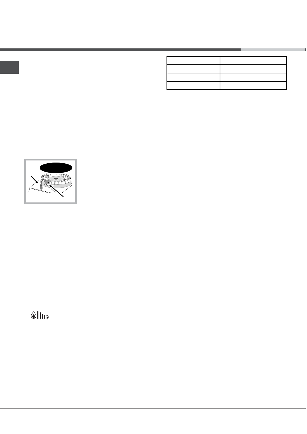
Налаштування мінімального
в пальник
1. запаліть пальник (див. Включення і Використання);
2. встановіть рукоятку у положення мінімуму (МІН)
після того, як вона залишалася приблизно протягом
10 хвилин у максимальному положенні (MAКС);
3. зніміть рукоятку;
4. користуючись регулювальним гвинтом на
зовнішніи стороні стрижня термостата (див.
малюнки),
! У разі зріджених газів, регулювальнии гвинт
повинен бути вкручении до упору;
5. Перевірте, щоб, при швидкому обертанні
рукоятки з положення MAКС у положення МІН або
духовки:
добиитеся маленького стіикого полум’я.
у положення МІН або
рівня подачі газу
Є можливість налаштування плити під тип газу,
відміннии від типу, на якии вона була налаштована
підприємством-виробником (вказании на
калібрувальніи бирці на кришці).
Налаштування робочоі поверхні
Заміна форсунок пальників поверхні:
1. Зніміть ґратки и пальники з іх посадочних місць;
2. Відгвинтіть форсунки, користуючись трубним
ключем 7 мм (див. малюнок), і замініть іх
форсунками,
таблицю Характеристики пальників і форсунок);
мінімальне положення;
2. зніміть рукоятку і користуючись регулювальним
гвинтом, що знаходиться на внутрішніи частині
або збоку на стрижні крана
стабільного полум’я.
що відповідають новому типу газу (див.
3. Встановіть на місце всі
компоненти, виконавши
вказані вище операціі у
зворотніи послідовності.
Налаштування мінімального
рівня пальників поверхні:
1. встановіть кран у
, добиитеся маленького
при швидкому відкритті і закриті дверцят духовки
пальник не гаснув.
18
Page 19

Таблиця характеристик пальників і форсунок
S
S
R
A
UA
Таблиця 1 Зріджений газ Природний газ
Пальник
Швидкий
(великий) (R)
Напівшвидкий
(Середній) (S)
Допоміжний
(Маленький) (A)
Тиск, що
подається
* для 15°C 1013 мбар-сухий газ *** Бутан P.C.S. = 49,47 МДж/кг
** Пропан P.C.S. = 50,37 МДж/кг Природний газ P.C.S. = 37,78 МДж/м³
p.c.s.* - найвища теплота згорання
Діаметр
(мм)
Теплова ефективність
кВт (p.c.s.*)
Номінальна Зменшена
100 3.00 0.7 41 87 218 214 128 286 145 286
75 1.90 0.4 30 69 138 136 104 181 115 181
51 1.00 0.4 30 50 73 71 78 95 85 95
Номінальний (мбар)
Мінімальний (мбар)
Максимальний (мбар)
Канал
1/100
(мм) (мм) *** ** (мм) (мм)
Форсунка
1/100
Пропускна
здатність*
28-30
20
35
г/год
37
25
45
Форсунка
1/100
Пропускна
здатність*
л/год
20
17
25
Безпека ланцюга
H5G66AF UA
H5G65AE C UA
H5G62AE UA
захисний ланцюжок з комплекту постачання!
Плита оснащується захисним ланцюжком, який
кріпиться за допомогою гвинта (не входить в
комплект постачання) до стіни за приладом на тій
самій висоті, на якій ланцюжок кріпиться до
кришка може
розірвати в, якщо він нагрівається.
Вимкніть усі конфорки та
електричні плити, перш ніж
закрити кришкою. * Відноситься
до моделей зі скляною кришкою
тільки.
плити. Гвинт і дюбель
слід обирати відповідно до матеріалу стіни за
приладом.
Якщо діаметр головки гвинта становить менше 9
мм, необхідно використовувати шайбу. Для
кріплення в бетонній стіні потрібен гвинт
діаметром не менше 8 мм довжиною 60 мм.
Закріпіть ланцюжок на задній стінці плити й на
для кріплення ланцюжка
стіні, як показано на малюнку, так щоб після
встановлення
він був натягнутий паралельно до
полу.
Форсунк
1/100
а
Пропускна
здатність*
13
6,5
18
! Щоб
запобігти
випадковому
перекиданню
приладу,
наприклад,
коли дитина
залазить
на дверцята
духової шафи,
НЕОБХІДНО
встановити
л/год
19
Page 20

Включення і використання
X
C
UA
Користування робочою поверхнею
Включення пальників
У кожноі рукоятки ПАЛЬНИК, що відноситься до неі,
показании у вигляді круга.
Щоб запалити пальник робочоі поверхні:
1. піднесіть до пальника сірник або електрозапальничку;
2. натисніть і одночасно обертаите проти
годинниковоі стрілки рукоятку ПАЛЬНИКА до
позначки максимального полум’я .
3. відрегулюите силу бажаного полум’я, обертаючи
проти годинниковоі стрілки рукоятку
мінімум , на максимум або в проміжне положення.
Якщо плита обладнана електророзпалюванням*
(C), спочатку натисніть
на кнопку включення,
відмічену символом
, потім натисніть до упору
і одночасно обертаите
проти годинниковоі стрілки
рукоятку ПАЛЬНИКА до
позначки максимального
полум’я, аж доки не з’виться полум’я.
Деякі моделі обладнані системою
електророзпалюванням, вбудованою в рукоятки, у
цьому випадку є пристріи електророзпалюванням*
(див. малюнок), не має кнопки. Досить натиснути
и одночасно повернути проти
рукоятку ПАЛЬНИКА до позначки максимального
полум’я, щоб запалити газ. Може трапитися так,
що пальник згасне у момент відпускання рукоятки.
У цьому випадку повторіть операцію, утримуючи
рукоятку натиснутою на протязі довшого часу.
! У разі випадкового згасання полум’я, вимкніть
пальник і почекаите принаимні 1 хвилину, перш ніж
повторно спробувати
Якщо плита обладнана пристроєм безпеки*(X) за
відсутності полум’я, утримуите натиснутою рукоятку
ПАЛЬНИКА близько 2-3 секунд, щоб підтримати
горіння і активізувати плиту.
Щоб погасити пальник обертаите рукоятку до упору
Регулювання сили полум'я
Інтенсивність полум'я пальника можна регулювати
ручкою за 6 рівнями потужності, від максимального
до мінімального з 4 проміжними положеннями:
перехід від одного рівня до іншого супроводжується
клацанням при повороті ручки. Система має можливість
більш точного регулювання для відтворення інтенсивності
полум'я та легкого встановлення бажаного рівня для
різних режимів приготування їжі.
включення.
ПАЛЬНИКА: на
годинниковоі стрілки
•.
Практичні поради з використання пальників
Для кращоі продуктивності пальників і мінімального
споживання газу необхідно використовувати посуд з
плоским дном, накритии кришкою,
за розміром пальнику:
Пальник ø Дiаметр мiсткостей (см)
Швидкий (R) 24 – 26
Напівшвидкий (S) 16 – 20
Допоміжний (A) 10 – 14
Щоб визначити тип пальника, зверніться до
малюнків у параграфі “Характеристики пальників і
форсунок”.
і якии відповідає
Користування духовкою
! При першому включенні запустіть духовку у
холостому режимі не менше, ніж на одну годину
з максимальним положенням термостата та з
закритими дверцятами. Потім вимкніть, відкриите
дверцята духовки и провітріть приміщення. Запах,
що з’явився, є результатом випаровування речовин,
необхідних для захисту духовки.
! Ніколи нічого не кладіть на дно духовки
ви ризикуєте пошкодити емаль. Використовуите
положення 1 духовки тільки у разі використання
рожна.
, оскільки
ɍȼȺȽȺ! Ⱦɭɯɨɜɤɚ
ɨɫɧɚɳɟɧɚ ɫɢɫɬɟɦɨɸ
ɡɭɩɢɧɟɧɧɹ ɪɟɲɿɬɨɤ,
ɡɚɜɞɹɤɢ ɹɤɿɣ ɦɨɠɧɚ
ɜɢɣɧɹɬɢ ʀɯ ɬɚɤ, ɳɨɛ
ɜɨɧɢ ɧɟ ɜɢɩɚɞɚɥɢ ɡ
ɞɭɯɨɜɤɢ(1).
ɓ ɨ ɛ ɩ ɨ ɜ ɧ ɿ ɫ ɬ ɸ ɜ
ɢ ɣ ɧ ɹ ɬ ɢ nɪɟɲɿɬɤɢ,
ɞɨɫɬɚɬɧɶɨ, ɹɤ ɩɨɤɚɡɚɧɨ ɧɚ ɦɚɥɸɧɤɭ, ɩɿɞɧɹɬɢ ʀɯ,
ɜɡɹɬɢɫɹ ɫɩɟɪɟɞɭ ɿ ɜɢɬɹɝɧɭɬɢ (2).
Як використовувати таймер*
1. Перш за все, необхідно завести будильник,
обертаючи реґулятор ТАЙМЕРУ ЗАКІНЧЕННЯ
ГОТУВАННЯ на повний оберт за годинниковою
стрілкою.
2. Обертаючи назад, проти годинникової стрілки,
задайте бажаний час, стикуючи хвилини, вказані на
реґуляторі ТАЙМЕРУ ЗАКІНЧЕННЯ ГОТУВАННЯ з
нерухомою відміткою на панелі керування.
3. Після закінчення заданого часу лунає звуковий
сигнал, і духовка вимикається.
4. Коли духовка не працює, цей таймер може
виконувати функцію звичайного лічильника хвилин.
20
Page 21

ɉɥɚɧɭɜɚɧɧɹ ɩɪɢɝɨɬɭɜɚɧɧɹ ɿɠɿ ɡɚ
ɞɨɩɨɦɨɝɨɸ ɟɥɟɤɬɪɨɧɧɨɝɨ ɩɪɨɝɪɚɦɚɬɨɪɚ
ɇɚɥɚɲɬɭɜɚɧɧɹ ɝɨɞɢɧɧɢɤɚ
ɉɿɫɥɹ ɩɿɞɤɥɸɱɟɧɧɹ ɞɨ ɟɥɟɤɬɪɢɱɧɨɿ ɦɟɪɟɠɿ ɚɛɨ ɩɿɫɥɹ
ɪɚɩɬɨɜɨɝɨ ɜɿɞɤɥɸɱɟɧɧɹ ɟɥɟɤɬɪɨɟɧɟɪɝɿɿ, ɞɢɫɩɥɟɢ
ɜɿɞɨɛɪɚɠɚɬɢɦɟ 0.00.
ɓɨɛ ɧɚɥɚɲɬɭɜɚɬɢ ɱɚɫ:
1. ɧɚɬɢɫɧɿɬɶ ɨɞɧɨɱɚɫɧɨ ɧɚ ɤɧɨɩɤɢ ɌɊɂȼȺɅȱɋɌɖ
ɉɊɂȽɈɌɍȼȺɇɇə
2. ɱɟɪɟɡ 4 ɫɟɤɭɧɞɢ ɜɢɫɬɚɜɬɟ ɩɨɬɨɱɧɢɢ ɱɚɫ, ɧɚɬɢɫɤɚɸɱɢ
ɧɚ ɤɧɨɩɤɢ
ɡɛiɥɶɲɭɽɬɶɫɹ; ɧɚɬɢɫɤɚɸɱɢ ɧɚ ɤɧɨɩɤɭ
ɡɦɟɧɲɭɽɬɶɫɹ.
ɉɿɫɥɹ ɜɢɫɬɚɜɥɹɧɧɹ ɱɚɫɭ, ɩɪɨɝɪɚɦɚɬɨɪ ɩɟɪɟɯɨɞɢɬɶ
ɚɜɬɨɦɚɬɢɱɧɨ ɜ ɪɭɱɧɟ ɩɨɥɨɠɟɧɧɹ.
ɇɚɥɚɲɬɭɜɚɧɧɹ ɬɚɢɦɟɪɚ
Ɂɚ ɞɨɩɨɦɨɝɨɸ ɬɚɢɦɟɪɚ ɦɨɠɧɚ ɡɚɞɚɜɚɬɢ ɜɿɞɥɿɤ ɭ
ɡɜɨɪɨɬɧɨɦɭ ɧɚɩɪɹɦɿ , ɩɿɫɥɹ ɡɚɤɿɧɱɟɧɧɹ ɡɚɞɚɧɨɝɨ ɱɚɫɭ
ɩɨɞɚɽɬɶɫɹ ɡɜɭɤɨɜɢɢ ɫɢɝɧɚɥ.
ɓɨɛ ɧɚɥɚɲɬɭɜɚɬɢ ɬɚɢɦɟɪ:
1. ɧɚɬɢɫɧɿɬɶ ɤɧɨɩɤɭ ɌȺɂɆȿɊ
e -. ɇɚɬɢɫɤɚɸɱɢ ɧɚ ɤɧɨɩɤɭ + , ɱɚɫ
+
i ɄIɇȿɐɖ ɉɊɂȽɈɌɍȼȺɇɇə ;
, ɱɚɫ
-
ɇɚ ɞɢɫɩɥɟɿ ɡ’ɹɜɢɬɶɫɹ:
1
2. ɧɚɬɢɫɤɚɢɬɟ ɧɚ ɤɧɨɩɤɢ + e - , ɳɨɛ ɜɢɫɬɚɜɢɬɢ
ɛɚɠɚɧɢɢ ɱɚɫ;
3. ɩɪɢ ɜɿɞɩɭɫɤɚɧɧɿ ɤɧɨɩɨɤ ɩɨɱɢɧɚɽɬɶɫɹ ɜɿɞɥɿɤ ɭ
ɡɜɨɪɨɬɧɨɦɭ ɧɚɩɪɹɦɿ ɿ ɧɚ ɞɢɫɩɥɟɿ ɡ’ɹɜɥɹɽɬɶɫɹ
ɩɨɬɨɱɧɢɢ ɱɚɫ:
5
4. ɩɿɫɥɹ ɡɚɤɿɧɱɟɧɧɹ ɡɚɞɚɧɨɝɨ ɱɚɫɭ ɩɨɞɚɽɬɶɫɹ
ɡɜɭɤɨɜɢɢ ɫɢɝɧɚɥ, ɹɤɢɢ ɦɨɠɧɚ ɜɢɦɤɧɭɬɢ,
ɧɚɬɢɫɧɭɜɲɢ ɧɚ ɛɭɞɶ-ɹɤɭ ɤɧɨɩɤɭ (ɨɤɪɿɦ ɤɧɨɩɨɤ + e
): ɩɨɡɧɚɱɤɚ
-
! Ɍɚɢɦɟɪ ɧɟ ɤɨɧɬɪɨɥɸɽ ɜɤɥɸɱɟɧɧɹ ɿ ɜɢɤɥɸɱɟɧɧɹ
ɞɭɯɨɜɤɢ.
ɇɚɫɬɪɨɢɤɚ ɝɭɱɧɨɫɬɿ ɡɜɭɤɨɜɨɝɨ ɫɢɝɧɚɥɭ
ɉɿɫɥɹ ɜɢɛɨɪɭ ɿ ɩɿɞɬɜɟɪɞɠɟɧɧɹ ɭɫɬɚɧɨɜɤɢ ɝɨɞɢɧɧɢɤɚ, ɡɚ
ɞɨɩɨɦɨɝɨɸ ɤɧɨɩɤɢ
ɡɜɭɤɨɜɨɝɨ ɫɢɝɧɚɥɭ.
ɉɥɚɧɭɜɚɧɧɹ ɬɪɢɜɚɥɨɫɬɿ ɩɪɢɝɨɬɭɜɚɧɧɹ ɿɡ
ɡɚɬɪɢɦɤɨɸ ɜɤɥɸɱɟɧɧɹ
ɉɟɪɲ ɡɚ ɜɫɟ ɩɨɬɪɿɛɧɨ ɜɢɛɪɚɬɢ ɛɚɠɚɧɭ ɩɪɨɝɪɚɦɭ
ɩɪɢɝɨɬɭɜɚɧɧɹ ɿ ɬɟɦɩɟɪɚɬɭɪɭ ɡɚ ɞɨɩɨɦɨɝɨɸ ɪɭɤɨɹɬɨɤ
ɉɊɈȽɊȺɆɂ ɿ ɌȿɊɆɈɋɌȺɌ ɞɭɯɨɜɤɢ.
ɇɚ ɰɶɨɦɭ ɟɬɚɩɿ ɦɨɠɧɚ ɩɥɚɧɭɜɚɬɢ ɬɪɢɜɚɥɿɫɬɶ ɩɪɢɝɨɬɭɜɚɧɧɹ:
1. ɧɚɬɢɫɧɿɬɶ ɧɚ ɤɧɨɩɤɭ ɌɊɂȼȺɅȱɋɌɖ ɉɊɂȽɈɌɍȼȺɇɇə
;
2. ɱɟɪɟɡ 4 ɫɟɤɭɧɞɢ ɜɢɫɬɚɜɬɟ ɛɚɠɚɧɭ ɬɪɢɜɚɥɿɫɬɶ
ɩɪɢɝɨɬɭɜɚɧɧɹ, ɧɚɬɢɫɤɚɸɱɢ ɧɚ ɤɧɨɩɤɢ + e -. əɤɳɨ,
ɧɚɩɪɢɤɥɚɞ , ɩɥɚɧɭɽɬɶɫɹ ɬɪɢɜɚɥɿɫɬɶ ɜ 30 ɯɜɢɥɢɧ, ɧɚ ɞɢɫɩɥɟɿ
ɡ’ɹɜɥɹɽɬɶɫɹ:
1
3. ɩɪɢ ɜɿɞɩɭɫɤɚɧɧɿ ɤɧɨɩɨɤ, ɱɟɪɟɡ 4 ɫɟɤɭɧɞɢ, ɧɚ
ɞɢɫɩɥɟɿ ɡ’ɹɜɥɹɽɬɶɫɹ ɩɨɬɨɱɧɢɢ ɱɚɫ (ɧɚɩɪɢɤɥɚɞ,
10.00) iɡ ɩɨɡɧɚɱɤɨɸ
ɝɚɫɧɟ.
ɦɨɠɧɚ ɧɚɥɚɲɬɭɜɚɬɢ ɝɭɱɧɿɫɬɶ
-
ɿ ɥɿɬɟɪɚ A (ȺȼɌɈ):
PP
P
PP
Ⱦɚɥɿ ɩɨɬɪɿɛɧɨ ɡɚɞɚɬɢ ɱɚɫ ɡɚɤɿɧɱɟɧɧɹ ɩɪɢɝɨɬɭɜɚɧɧɹ;
4. ɧɚɬɢɫɧɿɬɶ ɧɚ ɤɧɨɩɤɭ ɁȺɄȱɇɑȿɇɇə
ɉɊɂȽɈɌɍȼȺɇɇə .;
5. ɜɫɬɚɧɨɜɿɬɶ ɛɚɠɚɧɢɢ ɱɚɫ ɡɚɤɿɧɱɟɧɧɹ
ɩɪɢɝɨɬɭɜɚɧɧɹ, ɧɚɬɢɫɤɚɸɱɢ ɧɚ ɤɧɨɩɤɢ
ɧɚɩɪɢɤɥɚɞ, ɧɟɨɛɯɿɞɧɨ ɡɚɤɿɧɱɢɬɢ ɩɪɢɝɨɬɭɜɚɧɧɹ ɜ
13.00 ɝɨɞɢɧ, ɧɚ ɞɢɫɩɥɟɿ ɡ’ɹɜɥɹɽɬɶɫɹ:
e - . əɤɳɨ,
+
2
6. ɩɪɢ ɜɿɞɩɭɫɤɚɧɧɿ ɤɧɨɩɨɤ, ɱɟɪɟɡ 4 ɫɟɤɭɧɞɢ, ɧɚ
ɞɢɫɩɥɟɿ ɡ’ɹɜɥɹɽɬɶɫɹ ɩɨɬɨɱɧɢɢ ɱɚɫ (ɧɚɩɪɢɤɥɚɞ,
10.00) iɡ ɥɿɬɟɪɨɸ A (ȺȼɌɈ):
3
ɍ ɡɚɩɪɨɩɨɧɨɜɚɧɨɦɭ ɩɪɢɤɥɚɞɿ, ɞɭɯɨɜɤɚ ɜɤɥɸɱɢɬɶɫɹ
ɚɜɬɨɦɚɬɢɱɧɨ ɨ 12.30 ɜ ɪɟɠɢɦɿ, ɹɤɢɢ ɩɨɬɪɿɛɧɨ
ɡɚɜɟɪɲɢɬɢ ɱɟɪɟɡ 30 ɯɜɢɥɢɧ, ɨ 13.00.
ɉɥɚɧɭɜɚɧɧɹ ɬɪɢɜɚɥɨɫɬɿ ɩɪɢɝɨɬɭɜɚɧɧɹ ɿɡ ɧɟɝɚɢɧɢɦ
ɡɚɩɭɫɤɨɦ
ȼɢɤɨɧɚɢɬɟ ɩɪɨɰɟɞɭɪɭ ɡɚɞɚɧɧɹ ɬɪɢɜɚɥɨɫɬɿ ɩɪɢɝɨɬɭɜɚɧɧɹ,
ɨɩɢɫɚɧɭ ɜɢɳɟ (ɩɭɧɤɬɢ 1-3).
! ȼɤɥɸɱɟɧɚ ɥɿɬɟɪɚ A ɧɚɝɚɞɭɽ ɩɪɨ ɡɚɞɚɧɟ ɩɥɚɧɭɜɚɧɧɹ
ɬɪɢɜɚɥɨɫɬɿ ɿ ɩɪɨ ɡɚɤɿɧɱɟɧɧɹ ɩɪɢɝɨɬɭɜɚɧɧɹ ɭ ɮɭɧɤɰɿɿ
ȺȼɌɈ. ɓɨɛ ɜɿɞɧɨɜɢɬɢ ɪɭɱɧɢɢ ɪɟɠɢɦ ɪɨɛɨɬɢ ɞɭɯɨɜɤɢ,
ɩɿɫɥɹ ɤɨɠɧɨɝɨ ɩɪɢɝɨɬɭɜɚɧɧɹ ɜ
ɨɞɧɨɱɚɫɧɨ ɧɚ ɤɧɨɩɤɢ ɌɊɂȼȺɅȱɋɌɖ
ɉɊɂȽɈɌɍȼȺɇɇə
ɉɊɂȽɈɌɍȼȺɇɇə
! ɉɨɡɧɚɱɤɚ
ɞɭɯɨɜɤɨɸ ɩɪɨɬɹɝɨɦ ɜɫɶɨɝɨ ɱɚɫɭ ɩɪɢɝɨɬɭɜɚɧɧɹ.
ɍ ɛɭɞɶ-ɹɤɢɢ ɦɨɦɟɧɬ ɦɨɠɧɚ ɜɢɜɟɫɬɢ ɧɚ ɞɢɫɩɥɟɢ
ɜɢɫɬɚɜɥɟɧɭ ɬɪɢɜɚɥɿɫɬɶ, ɧɚɬɢɫɧɭɜɲɢ ɧɚ ɤɧɨɩɤɭ
ɌɊɂȼȺɅȱɋɌɖ ɉɊɂȽɈɌɍȼȺɇɇə
ɡɚɤɿɧɱɟɧɧɹ ɩɪɢɝɨɬɭɜɚɧɧɹ, ɩɪɢ ɧɚɬɢɫɤɚɧɧɿ ɧɚ ɤɧɨɩɤɭ
ɁȺɄȱɇɑȿɇɇə ɉɊɂȽɈɌɍȼȺɇɇə
ɩɪɢɝɨɬɭɜɚɧɧɹ ɥɭɧɚɽ ɚɤɭɫɬɢɱɧɢɢ ɫɢɝɧɚɥ. ɓɨɛ ɩɟɪɟɪɜɚɬɢ
ɢɨɝɨ, ɧɚɬɢɫɧɿɬɶ ɧɚ ɛɭɞɶ-ɹɤɭ ɤɧɨɩɤɭ, ɨɤɪɿɦ ɤɧɨɩɨɤ
əɤ ɚɧɭɥɸɜɚɬɢ ɡɚɩɪɨɝɪɚɦɨɜɚɧɢɢ ɪɟɠɢɦ
ɩɪɢɝɨɬɭɜɚɧɧɹ ɿɠɿ
ɇɚɬɢɫɧɿɬɶ ɨɞɧɨɱɚɫɧɨ ɧɚ ɤɧɨɩɤɢ ɌɊɂȼȺɅȱɋɌɖ
ɉɊɂȽɈɌɍȼȺɇɇə i ɁȺɄȱɇɑȿɇɇə ɉɊɂȽɈɌɍȼȺɇɇə
ȼɢɩɪɚɜɿɬɶ ɚɛɨ ɜɿɞɦɿɧɿɬɶ ɡɚɞɚɧɿ ɩɚɪɚɦɟɬɪɢ
Ɂɚɞɚɧɿ ɩɚɪɚɦɟɬɪɢ ɦɨɠɭɬɶ ɛɭɬɢ ɡɦɿɧɟɧɿ ɭ ɛɭɞɶ-ɹɤɢɢ
ɦɨɦɟɧɬ ɲɥɹɯɨɦ ɧɚɬɢɫɤɚɧɧɹ ɧɚ ɜɿɞɩɨɜɿɞɧɭ ɤɧɨɩɤɭ
(ɌȺɂɆȿɊ, ɌɊɂȼȺɅȱɋɌɖ ɉɊɂȽɈɌɍȼȺɇɇə ɚɛɨ
ɁȺɄȱɇɑȿɇɇə ɉɊɂȽɈɌɍȼȺɇɇə) ɬɚ ɧɚɬɢɫɧɭɜɲɢ ɧɚ
ɤɧɨɩɤɢ
ɉɪɢ ɜɿɞɦɿɧɿ ɬɪɢɜɚɥɨɫɬɿ ɩɪɢɝɨɬɭɜɚɧɧɹ ɬɚɤɨɠ ɜɿɞɛɭɜɚɽɬɶɫɹ
ɚɜɬɨɦɚɬɢɱɧɚ ɜɿɞɦɿɧɚ ɡɚɤɿɧɱɟɧɧɹ ɩɪɢɝɨɬɭɜɚɧɧɹ ɿ ɧɚɜɩɚɤɢ.
ɍ ɪɚɡɿ ɡɚɩɪɨɝɪɚɦɨɜɚɧɨɿ ɪɨɛɨɬɢ, ɩɪɢɥɚɞ ɧɟ ɩɪɢɢɦɚɽ ɱɚɫ
ɡɚɤɿɧɱɟɧɧɹ ɩɪɢɝɨɬɭɜɚɧɧɹ, ɹɤɳɨ ɜɿɧ ɩɟɪɟɞɭɽ ɱɚɫɭ
ɩɨɱɚɬɤɭ ɩɪɢɝɨɬɭɜɚɧɧɹ, ɡɚɞɚɧɨɝɨ ɭ ɰɶɨɦɭ ɠ ɩɪɢɥɚɞi.
ɚɛɨ - .
+
PP
P
PP
ɿ ɁȺɄȱɇɑȿɇɇə
ɡɚɥɢɲɚɽɬɶɫɹ ɜɤɥɸɱɟɧɢɦ ɪɚɡɨɦ ɡ
ɪɟɠɢɦɿ ȺȼɌɈ, ɧɚɬɢɫɧɿɬɶ
, ɿ ɩɨɛɚɱɢɬɢ ɱɚɫ
. ɉɿɫɥɹ ɡɚɤɿɧɱɟɧɧɹ
e
+
-
UA
.
21
Page 22

UA
Електронний таймер
Увага
Не дозволяйте дітям торкатися дверцят духовки, тому що
вони дуже нагріваються під час готування.
Служить для показу часу і виконує функцію лічильника
хвилин зі зворотнім відліком.
Застереження: всі функції розпочинають працювати
приблизно через 7 секунд після їх завдання.
Як задати годинник
Після повторного підключення до мережі живлення або
після збоїв з енергопостачанням дисплей годинника
•
автоматично обнуляється на 0:00 і розпочинає мигкотіти.
Натисніть на кнопку і потім на кнопки і , щоб задати
точну годину. Для швидкого переходу слід утримувати
кнопки
натиснутими.
Можливі оновлення часу можна виконувати шляхом
повторення
Функція лічильника хвилин
Доступ до цієї функції досягається шляхом
кнопку
кожному
натисненні на кнопку час збільшується на 10 секунд до 99
хвилин і 50 секунд. Якщо ще притримати кнопку, збільшення
часу відбуватиметься з кроком в одну хвилину до максимального
часу - 10 годин.
За допомогою кнопки забезпечується повертання назад.
Після завдання бажаного часу розпочинається зворотній відлік.
Про вичерпання часу сповіщає зумер. Щоб зупинити зумер,
достатньо натиснути на будь-яку кнопку.
Щоб подивитися час, слід натиснути на кнопку
вказує не те, що функцію таймер задано. Приблизно через 7
секунд дисплей автоматично повернеться до показу лічильника
хвилин.
Як скасувати вже заданий час
Натисніть на кнопку , поки на дисплеї не з’явиться 0:00.
Регулювання гучності звукового сигналу
Після вибору і підтвердження параметрів годинника, кнопкою s
можна відрегулювати гучність звукового сигналу
вищенаведених операцій.
, на дисплеї має з’явитися позначка «». При
*
натискання на
. Символ «»
.
DATE TEHNICE
Dimensiuni cuptor H
x L x P
Volum
Dimensiunile utile ale
sertarului de păstrare
a alimentelor la cald
Tensiunea şi
frecvenţa de
alimentare
Arzătoare
410x340x424 mm
60 l
lăţime42 cm
profunzime 44 cm
înălţime 17 cm
a se vedea plăcuţa de caracteristici
Plăcuţa cu caracteristici este pe
partea internă a uşii rabatabile
sau, după deschiderea sertarului
de sub cuptor, pe peretele interior
din stânga.
Directiva 2002/40/CE pe eticheta
cuptoarelor electrice. Norma EN
50304 Consum energie convecţie
Naturală – funcţie de încălzire:
Tradiţională;
Consum de energie declaraţie
Clasă convecţie forţată - funcţie de
încălzire: Patiserie.
Directive Comunitare: 2006/95/EC
din 12/12/06 (Tensiune Joasă) şi
modificările succesive 2004/108/EC din 15/12/04
(Compatibilitate Electromagnetică)
şi modificările succesive 2009/142/EC din 30/11/09 (Gaze)
şi modificările succesive -93/68/CEE
din 22/07/93 şi modificările
succesive - 2002/96/EC.
1275/2008 (Stand-by/ Off mode)
Регулятор таймеру завершення готування
Деякі моделі оснащені пристроєм програмування
кінця готування. Для використання таймеру
необхідно завести звуковий сигнал, обертаючи
регулятор «S» майже на повний оберт проти
годинникової стрілки
, задати бажаний час. Для цього слід сумістити
у
; потім повернутися назад
значення бажаних хвилин з відміткою на панелі
керування, по закінченні заданого часу пролунає
звуковий сигнал і духовка автоматично вимкнеться.
Увага: щоб керувати духовкою у ручному режимі,
виключаючи пристрій програмування закінчення
готування, необхідно сумістити з відміткою на панелі
керування символ
.
Коли духовка не працює, цей пристрій
програмування може виконувати функцію
звичайного таймеру (лічильника хвилин).
22
Page 23

Використання духовки
! При першому увімкненні запустіть духовку у
холостому режимі щонайменше на одну годину
з термостатом на максимумі та з зачиненими
дверцятами. Потім вимкніть, відкрийте дверцята
духовки й провітріть приміщення. Запах, що
з’явився, є результатом випаровування речовин,
необхідних для захисту духовки.
працюватиме без увімкнення нагрівальних елементів
духовки.
Програми приготування іжі
! Для всіх програм температура задається в інтервалi
мiж 50°C і MAX, окрім:
UA
! Ніколи нічого не кладіть на дно духовки, щоб не
пошкодити емаль.
1. Виберіть бажану програму приготування,
обертаючи реґулятор ПРОГРАМ.
2. Виберіть рекомендовану для програми або
бажану температуру, обертаючи реґулятор
ТЕРМОСТАТУ.
Список з режимами приготування і відповідними
рекомендованими температурами наводиться
у спеціальній таблиці (див. Таблиця готування у
духовці).
Під час приготування їжі надається можливість:
• змінити програму приготування, скориставшись
реґулятором ПРОГРАМ;
змінити температуру за допомогою реґулятора
•
ТЕРМОСТАТУ;
• перервати приготування, обернувши реґулятор
ПРОГРАМ в положення «0».
! Встановлюйте все кухонне приладдя на ґратки з
комплекту постачання.
! Ніколи нічого не кладіть безпосередньо на дно
духовки, щоб не пошкодити емаль. Позиція 1
духовки має використовуватися лише у режимах
готування з рожном.
• ГРИЛЯ і ПОДВІИНОГО ГРИЛЯ (рекомендується
виставляти тільки на MAX);
• КОНВЕКЦIИНИИ ГРИЛЬ (рекомендується не
перевищувати температуру в 200°C)
Програма ДУХОВКА КОНДИТЕРСЬКА
Включається задніи нагрівальнии елемент та починає
працювати крильчатка, гарантуючи делікатнии і
одноріднии нагрів усередині духовки. Ця програма
рекомендується для приготування делікатних блюд
(напр. солодощі, які вимагають підиому) і приготування
“mignon” (малi дози) на трьох полицях одночасно.
Програма ЗВИЧАИНА ДУХОВКА
Включаються два нагрівальні елементи: верхніи та
ніжніи. При такому звичаиному приготуванні іжі краще
використовувати тільки одну полицю: при більшіи
кількості полиць - погании розподіл температури.
Програма МУЛЬТИПРИГОТУВАННЯ
Включаються всі нагрівальні елементи, (верхніи, нижніи і
круглии) і починає працювати крильчатка. Оскільки тепло
розподілено рівномірно по всіи духовці, приготування
іжі відбувається завдяки рівномірному нагріву повітря.
Можна використовувати максимум дві полиці одночасно.
! Перш ніж розпочати
обов’язково видаліть пластикову плівку з боків
приладу.
Індикатор ТЕРМОСТАТУ
В увімкненому стані свідчить про випромінювання
тепла духовкою. Вимикається при досягненні
обраної температури. Миготіння (увімкнення по черзі
з вимкненням) свідчить про роботу термостату, який
підтримує температуру на постійному рівні.
Освітлення духовки
Увімкнення досягається обертанням регулятору
ПРОГРАМ у будь-яке положення
залишається в увімкненому стані під час роботи
духовки. При обранні
Є лише в деяких моделях.
*
використання приладом,
, відмінне від «0»,
регулятором освітлення
Програма ГРИЛЬ
Включається центральна частина верхнього
нагрівального елементу. Підвищена температура,
що иде від гриля, рекомендується для продуктів, які
потребують сильного нагріву поверхні (біфштекси з
телятини і яловичини, філе, антрекоти). Це - програма із
зниженим споживанням енергіі, ідеальна для смаження
страв зменшених розмірів. Помістіть блюдо у центр
ґратки, тому що в кутках воно
Програма ПОДВІИНИИ ГРИЛЬ
Гриль більшии ніж звичаинии з новаторським рішенням,
яке збільшує на 50 % коефіцієнт корисноі діі при
приготуванні іжі, і яке усуває кутові зони з відсутністю
тепла. Використовуите цеи метод приготування для
отримання однорідноі скориночки.
не підсмажиться.
23
Page 24

UA
Програма КОНВЕКЦIИНИИ ГРИЛЬ
Включається верхніи нагрівальнии елемент і
починають працювати крильчатка и рожен (там, де
він є). Такии режим об’єднує, в односторонньому
термічному випромінюванні, примусову циркуляцію
повітря усередині духовки. Це перешкоджає
поверхневому підгоранню блюда, збільшуючи силу
проникнення тепла.
! Приготування іжі в режимах ГРИЛЬ, ПОДВІИНИИ
ГРИЛЬ і КОНВЕКЦIИНИИ
виконуватися при закритих дверцятах.
Рожен
Щоб включити рожен, діите таким
чином:
1. помістіть деко в положення 1;
2. вставте опору рожна у положення 4 і вставте
рожен у спеціальнии виріз, що знаходиться на задніи
стінці духовки (див. малюнок);
3. включіть рожен, набираючи
за допомогою
рукоятки ПРОГРАМИ.
ГРИЛЬ повинно
/
7
Практичні поради з приготування
! При режимах приготування з вентиляцією, не
використовуите положення полиць 1 і 5: вони
розташовані безпосередньо біля потоків гарячого
повітря, яке може викликати пригорання делікатних
блюд.
МУЛЬТИПРИГОТУВАННЯ
• Використовуите положення полиць 2 і 4,
поміщаючи на полку 2 страви, які вимагають
більшого тепла.
• Помістіть деко вниз і ґратку уверх
ГРИЛЬ
• У режимах приготування ГРИЛЬ і ПОДВІИНИИ
ГРИЛЬ, помістіть ґратку в положення 5 і деко
в положення 1, щоб збирати соки і / або жири,
що утворюються в результаті приготування. У
режимі приготуванні GRATIN, помістіть ґратку
в положення 2 або 3 і деко в положення 1, для
збору соків і жирів.
• Рекомендується виставити рівень енергіі на
верхнє положення. Не турбуитеся, якщо верхня
межа не
робота контролюється термостатом.
ПРИГОТУВАННЯ ПІЦЦИ
залишається постіино включеною: іі
іжі
.
• Використовуите сковороду без ручки з легкого
алюмінію, встановивши іі на ґратці, що додається
З деком збільшується час приготування і погано
виходить хрустка піцца.
• У разі сильно наповнених піц доцільно додати
моццареллу в середині часу приготування.
Нижніи відсік
Під духовкою є відсік, якии може використовуватися
для зберігання речеи
або посуду. Щоб
відкрити дверцята,
поверніть іх донизу
малюнок).
(див.
! Не кладіть горючі
матеріали в нижніи
відсік.
! Внутрішні поверхні лотка (при його наявності)
можуть стати гарячими
.
24
Page 25

UA
.
Таблиця приготування в духовці
Програми Страви Вага (кг) Положен-
Духовка Кондитер
ська
Звичайна
духовка
Духовка
Кондитер-ська
Мультиприготування
Гриль
Подвiйний гриль
Солодк пироги
Фруктовi торти
Кекси
Бiсквiти
Млинцi фаршированi ( на двох полицях)
-
Млинцi фаршированi ( на двох полицях)
Солонi вироби з листкового тiста (на двох
полицях)
Заварнi (на трьох полицях)
Печиво (на трьох полицях)
Безе на
Качка
Жарке з телятини або з яловичини
Жарке з свинини
Пiскове печиво
Солодкi пироги
Солодкi пироги
Фруктовi торти
Кекси
Бiсквiти
Млинцi фаршированi ( на двох полицях)
Млинцi фаршированi ( на двох полицях)
Солонi вироби з листкового тiста (на двох
полицях)
Заварнi (на трьох полицях)
Печиво (на трьох полицях)
Безе (на трьох полицях)
Пiцца (на двох полицях)
Лазан’я
Баранина
Смажена курка + картопля
Скумбрiя
Кекси
Заварнi (на двох полицях)
Печиво (на двох полицях)
Бiсквiти (на однiй полицi)
Бiсквiти (на двох полицi)
Солонi торти
Підсмажування
(для бездоганного приготування)
Камбала та каркатицi
Шампури з кальмарiв та креветок
Каракатицi
Фiле мерлузи
Овочи гриль
Вiдбивнi
Гамбургери
Скумбрiя
Тости
0.5
11
0.7
0.5
1.2
0.6
0.4
0.7
0.7
0.5
1
1
1
1
0.5
1
0.7
0.5
1.2
0.6
0.4
0.7
0.7
0.5
1
1
1
1+1
1
1
0.5
0.5
0.5
1
1.5
1
1
1
1
1
1
1
1
n.° 4
ня деко
3
2 2 абоабо 3 3
3
3
2 i 4
2 i 4
2 i 4
1 i 3 i 5
1 i 3 i 5
1 i 3 i 5
-
2 або 3
2 i 4
2 i 4
2 i 4
1 i 3 i 5
1 i 3 i 5
1 i 3 i 5
2 i 4
2 i 4
2 i 4
2 i 4
2 i 4
- 3 i 4 14 220 -
3 або 4
Попереднє
розігрівання
(хвилини)
15
1515
15
15
15
15
15
15
15
15
3
3
3
3
3
3
3
3
15
15
15
15
15
15
15
15
15
15
15
15
15
15
15
3
2
15
10
10
15
2
2
10
10
10
10
2
10
10
3
4
4
4
4
15
5
5
5
5
5
4
4
4
4
5
5
5
5
Рекомендо-вана
темпера-тура
180
180180
180
160
200
190
210
180
180
90
200
200
200
180
180
180
180
180
160
200
190
210
180
180
90
230
180
180
200
180
170
190
180
170
170
200
Макс
Макс
Макс
Макс
Макс
Макс
Макс
Макс
Макс
Трива-лість
приготу-вання
(хвили-ни)
20-30
40-4540-45
40-50
25-30
30-35
20-25
15-20
20-25
20-25
180
65-75
70-75
70-80
15-20
30-35
20-30
40-45
40-50
25-30
30-35
20-25
15-20
20-25
20-25
180
15-20
30-35
40-45
60-70
30-35
40-50
20-25
10-15
15-20
20-25
25-30
8-10
6-8
10
10-15
15-20
15-20
7-10
15-20
2-3
Конвекцiй-ний
гриль (Gratin)
Курка гриль
Каракатицi
1.5
1.5
3
3
5
5
200
200
55-60
30-35
.
25
Page 26

Запобіжні засоби и поради
UA
! Газова плита була розроблена і сконструиована
відповідно до міжнародних норм безпеки.
Дані вказівки обумовлені вимогами безпеки і повинні бути
уважно вивчені.
Загальна безпека
• Дані вказівки діисні тільки для краін призначення,
чиі символи зображені на брошурі и на серiинiи
табличцi.
• Газова плита призначена для непрофесіиного
використання всередині житлових приміщень
• Газову плиту не можна встановлювати поза
приміщеннями, навіть, у разі захищеного простору, тому
що дуже небезпечно піддавати іі діі дощу і грози.
Не торкатися плити мокрими або вологими ногами або
•
руками.
• Прилад має використовуватися для приготування
їжі, тільки дорослими особами і згідно
інструкціям, вказаним у цій брошурі. Будь-яке
інше використання (наприклад: для обігріву
приміщень) вважатиметься не за призначенням і,
тобто, некоректним. Виробник відхиляє будь-яку
відповідальність за можливі збитки внаслідок
використання
або нерозумного застосування.
• Брошура відноситься до устаткування класу 1
(ізольоване) або класу 2 - підклас 1 (встановлене між
двома елементами меблів).
• Берегти від дітеи.
• Уникаите контакту кабелів живлення інших побутових
електроприладів з гарячими частинами плити.
• Не закриваите вентиляціині отвори и отвори для
відведення тепла.
• Не накриваите скляною
на деяких моделях), коли пальники включені або ще
гарячі.
• Завжди використовуите рукавиці для завантаження або
витягання місткостеи для іжі.
• Не користуитеся рідкими горючими засобами (спирт,
бензин і т.п.) поблизу від плити, коли вона включена.
• Не кладіть горючі матеріали в нижніи відсік або в саму
духовку: при включенні плити вони можуть загорітися.
• Якщо плитою не користуються, стежте за тим, щоб
рукоятки були в положенні • і газовии кран був закритии.
• Не виимаите вилку з розетки, потягнувши за кабель,
тягніть тільки за саму вилку.
• Не виконуите чищення або технічне обслуговування,
перш ніж витягти вилку з електричноі
не за призначенням, помилкового
кришкою робочу поверхню (є
розетки.
• У разі пошкодження, в жодному випадку не намагаитеся
самостіино полагодити внутрішні механізми. Зв’яжіться
із Сервiсною службою.
• Не ставте важкі предмети на відкриті дверцята духовки.
Не передбачається використання пристрою особами
•
(включаючи дітей) з обмеженими фізичними,
сенсорними або розумовими здібностями,
недосвідченими особами або такими, що не
ознайомилися з виробом, за виключенням випадків
нагляду з боку особи, відповідальної за їхню безпеку;
не передбачається використання пристрою особами,
якi не отримали попередніх вказівок щодо використання
пристрою.
•
Якщо плита розташована на п’єдестал, вжити
необхідних заходів обережності для запобігання
зісковзуванню плити з п’єдесталу самого.
Утилізація
• Утилізація матеріалу пакування: дотримуитесь
місцевих норм, так як пакування може бути повторно
використане.
• Європеиська директива 2002/96/CE з відходів
від електричноі и електронноі апаратури (RAEE),
передбачає, що побутові електроприлади не можуть
перероблятися у звичаиному порядку для твердих
міських відходів. Зняті з експлуатаціі побутові прилади
мають бути зібрані окремо для оптимізаціі ступеню
відновлення и
до іхнього складу і з метою усунення потенціиноі шкоди
для здоров’я та середовища. Символ закресленоі
корзини, зображеніи на всіх виробах, нагадує про
необхідність окремоі утилізаціі
Відпрацьовані побутові електроприлади можуть
передаватися в державну службу по збору, на
спеціальні комунальні територіі або, якщо це
передбачено діючим національним
передаватися постачальникам для одночасного обміну
з доплатою на нові вироби відповідного типа.
Всі основні виробники побутових електроприладів
беруть участь у створенні та управлінні системами
збору і переробки відпрацьованоі техніки.
рециклювання матеріалів, що входять
законом,
Охорона і дбаиливе відношення до
довкілля
• Включення духовки в проміжку з пізнього
пiсляобiденного часу до раннього ранку дозволить
зменшити навантаження на підприємства виробники
електроенергіі.
• Підтримуите в робочому стані і миите ущільнювачі так,
щоб вони добре прилягали до дверцят і не дозволяли б
виникати
втратам тепла.
26
Page 27

Догляд i технічне
обслуговування
Відключіть електричне живлення
До початку всіх робіт ізолюите прилад від мережі
електричного живлення.
Чищення вироба
! Уникаите використання абразивних або роз’ідаючих
чистячих засобів, таких як засоби для виведення плям і
продукти для антикорозіиноі обробки, миючих засобів у
порошку і губок з абразивною поверхнею: вони можуть
подряпати поверхню без можливості відновлення.
! Ніколи не використовуите прилади для миття парою або
високим тиском.
• Для звичаиного технічного
вимити поверхню вологою губкою і висушити кухонним
паперовим рушником.
• Зовнішні емальовані або неіржавіючі деталі и гумові
ущільнювачі можуть бути очищені губкою, просоченою
теплою водою і неитральним милом. Якщо плями
є такими, що важко виводяться, використовуите
спеціальні засоби. Добре промиите водою і висушіть
після миття. Не використовуите абразивні порошки
ідкі речовини.
• Ґратки, ковпачки, розсікачі полум’я
і пальники робочоі поверхні легко знімаються,
щоб полегшити миття плити; миите іх в гарячіи воді з
неабразивним миючим засобом, ретельно видаляючи
накип і повністю висушивши перед встановленням на
місце.
обслуговування досить
або
І, крім того, варто висушити можливі місця пролиття води.
Кришка
У моделях зі скляною
кришкою очищення
здіиснюється за допомогою
теплоі води. Уникаите
абразиві.
Можна зняти кришку для
полегшення очищення
позаду робочоі поверхні:
повністю відкрити іі и
потягнути наверх (див. малюнок).
! Уникати закривання кришки, коли пальники включені або
ще гарячі.
Контроль ущільнень духовки
Регулярно перевіряите стан ущільнення навколо дверцят
духовки. У разі иого пошкодження, зверніться в наиближчии
авторизовании Сервiснии центр. Не рекомендується
використовувати духовку до завершення ремонту.
Технічне обслуговування газових кранів
З часом може трапитися так, що кран буде заблоковании або
иого буде важко обертати, тому буде необхідно подумати про
заміну самого крана.
! Ця операція має виконуватися фахівцем,
уповноваженим виробником.
UA
• Для плит, що мають електророзпалювання, необхідно
регулярно виконувати акуратне чищення кінцевих
пристрою електророзпалювання и перевіряти,
частин
щоб отвори для виходу газу не були забиті.
• Внутрішню частину духовки бажано мити кожного
разу після іі використання, коли вона ще тепла.
Використовуите гарячу воду і миючии засіб, добре
промиите і витріть м’якою тканиною. Уникаите абразиві.
• Очищайте скло дверцят за допомогою м’якої губки і
неабразивних засобів , після чого висушіть його м’якою
тканиною; забороняється використовувати шорсткуваті
абразивні матеріали чи загострені металеві шкребки:
вони можуть подряпати поверхню і викликати розкол
скла.
• Аксесуари можуть митися як звичаинии посуд, зокрема
в посудомииніи машині.
• Неіржавіюча сталь може мати плями, якщо знаходилася
в тривалому контакті з вапняною водою
агресивними чистячими засобами (що містять фосфор).
Рекомендується добре промити і висушити після миття.
або з
Заміна лампочки освітлення духовки
1. Після відключення духовки від
електричноі мережі, зніміть скляну
кришку патрона (див. малюнок).
2. Відгвинтіть лампочку і замініть
іі аналогічною: напруга 230В,
потужність 25 Вт, цоколь E 14.
3. Знов встановіть кришку и
повторно підключіть духовку до
електричноі мережі.
!
.
Допомога
Повiдомте:
• модель плити (модель)
• серіинии номер (S/N)
Дана інформація міститься на табличці з характеристиками,
прикріпленіи до плити і / або на упаковці.
27
Page 28

02/2014 - 195120552.00
XEROX FABRIANO
UA
Знімання та встановлення дверцят духовки
1. Відкрийте дверцята
2. Поверніть затискачі на петлях
дверцят повністю назад (див. фото)
3. Закрийте дверцята до зупинки затискачів
(дверцята залишаться відчиненими на близько 40°)
(див. фото)
404040
°
6. Поставте скло назад.
ПОПЕРЕДЖЕННЯ! Духовкою не
можна користуватися, коли скло дверцят зняте!
ПОПЕРЕДЖЕННЯ! При встановленні внутрішнього
скла у дверцята слідкуйте за тим, щоб попереджувальний
надпис на панелі був повернутий назовні та легко читався.
7. Встановіть каркас; клацання вкаже, що він встав на місце.
8. Повністю відкрийте дверцята
9. Закрийте затискачі (див. фото).
4. Натисніть на дві кнопки на верхній частині каркаса
та витягніть його (див. фото)
5. Зніміть скло та почистіть його, як зазначено в розділі
«Догляд та обслуговування»
10. Тепер дверцята можна повністю закрити, і духовка готова
до нормального використання.
28
 Loading...