

Operating Instructions
Please phone us on
08448 24 24 24
to activate your
guarantee
HOB
GB
English,1
GA 750 X
GX 751 R T X
GA 750 T X
GA 640.1 R X
GA 641 X
GA 761 R F X
GX 641 R X
GA 630 R T X
GB 750 X
GB 640.1 R X
GB 641 X
GB 630 R T X
Contents
GB
Installation, 2-7
Positioning
Gas connection
Data plate
Burner and nozzle specifications
Electrical connection, 8
Description of the appliance, 9
Overall view
Start-up and use, 10-11
Practical advice on using the burners
Precautions and tips, 12
General safety
Disposal
Recycling & Disposal Information
Maintenance and care, 13
Switching the appliance off
Cleaning the appliance
Gas tap maintenance
Troubleshooting, 14
After Sales Service, 15
Repair Service and Information Desk
Extended Warranties
Genuine Parts and Accessories
Guarantee, 16
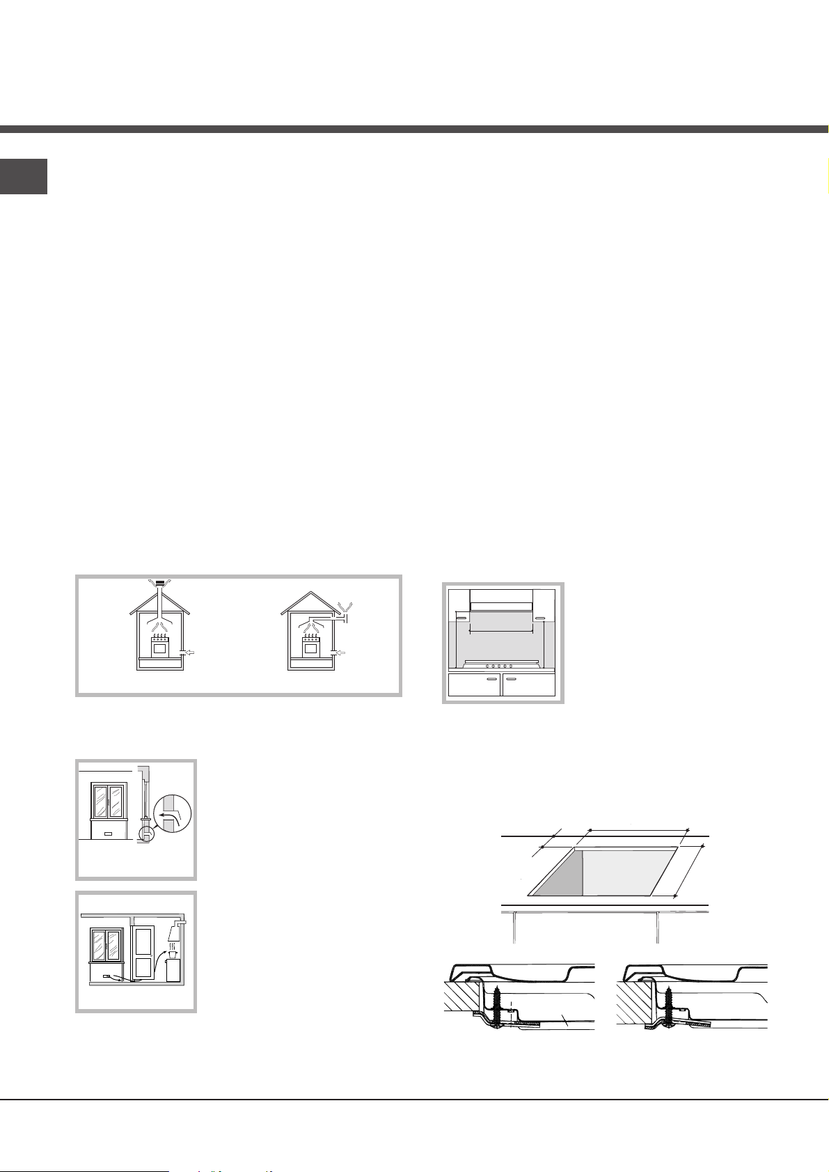
Installation
Enlarging the ventilation slot
between window and floor.
Adjacent
Room
Room to be
Vented
A
Examples of ventilation holes
for comburant air.
In a chimney stack or branched flue.
(exclusively for cooking appliances)
Directly to
the Outside
600mm min.
600mm min.
700mm min.
GB
! Before operating your new appliance please read this
instruction booklet carefully. It contains important
information for safe use, installation and care of the
appliance.
! Please keep these operating instructions for future
reference. Pass them on to possible new owners of the
appliance.
Positioning
! Keep packaging material out of the reach of children. It
can become a choking or suffocation hazard (
Precautions and tips
).
! The appliance must be installed by a qualified
professional according to the instructions provided.
Incorrect installation may cause harm to people and
animals or may damage property.
! This unit may be installed and used only in permanently
ventilated rooms in accordance with British Standard
Codes Of Practice: B.S. 6172 / B.S. 5440, Par. 2 and B.S.
6891 Current Editions. The following requirements must be
observed:
• The room must be equipped with an air extraction
system that expels any combustion fumes. This may
consist of a hood or an electric fan that automatically
see
• Liquid petroleum gas sinks to the floor as it is heavier
than air. Therefore, rooms containing LPG cylinders
must also be equipped with vents to allow gas to
escape in the event of a leak. As a result LPG
cylinders, whether partially or completely full, must not
be installed or stored in rooms or storage areas that are
below ground level (cellars, etc.). It is advisable to
keep only the cylinder being used in the room,
positioned so that it is not subject to heat produced by
external sources (ovens, fireplaces, stoves, etc. ) which
could raise the temperature of the cylinder above 50°C.
Fitting the appliance
Gas and mixed hobs are manufactured with type X
degree protection against overheating. The following
precautions must be taken when installing the hob:
• Kitchen cabinets adjacent to the appliance and taller
than the top of the hob must be at least 600 mm from
the edge of the hob.
• Hoods must be installed according to their relative
installation instruction manuals and at a minimum
distance of 650 mm from the hob.
• Place the wall cabinets adjacent to the hood at a
minimum height of 420 mm from the hob (
see figure
).
starts each time the appliance is switched on.
• The room must also allow proper air circulation, as air is
needed for combustion to occur normally. The flow of
air must not be less than 2 m
per kW of installed power.
The air circulation system may
take air directly from the outside
by means of a pipe with an inner
cross section of at least 100
2
; the opening must not be
cm
vulnerable to any type of
blockages.
The system can also provide the
air needed for combustion
indirectly, i.e. from adjacent
rooms fitted with air circulation
tubes as described above.
However, these rooms must not
be communal rooms, bedrooms
or rooms that may present a fire hazard.
If the hob is installed beneath a
wall cabinet, the latter must be
situated at a minimum of 700 mm
above the hob (
see figure
).
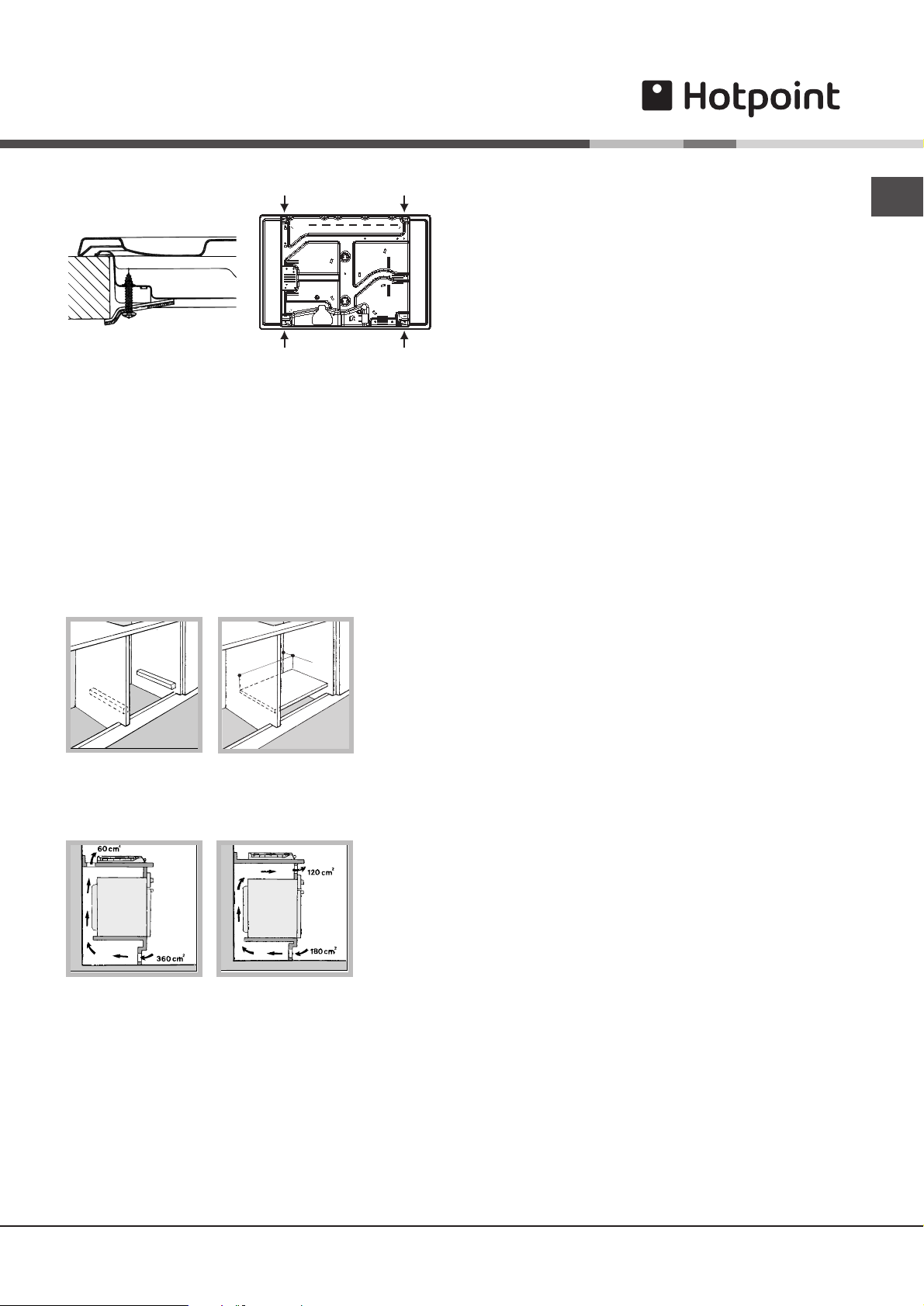
• The installation cavity should have the dimensions
indicated in the figure.
3
/h
Fastening hooks are provided, allowing you to fasten
the hob to tops that are between 20 and 40 mm thick.
To ensure the hob is securely fastened to the top, we
recommend you use all the hooks provided.
555 mm
55 mm
475 mm
Hook fastening diagram
Hooking position Hooking position
for top H=20 mm for top H=30 mm
PLEASE PHONE US TO REGISTER YOUR APPLIANCE AND ACTIVATE YOUR PARTS GUARANTEE ON 08448 24 24 24
2
Front
560 m
m
.
4
5
m
m
.
Hooking position Back
for top H=40 mm
! Use the hooks contained in the “accessory pack”
• Where the hob is not installed over a built-in oven, a
wooden panel must be installed as insulation. This
must be placed at a minimum distance of 20 mm from
the lower part of the hob.
Ventilation
To ensure adequate ventilation, the back panel of the
cabinet must be removed. It is advisable to install the
oven so that it rests on two strips of wood, or on a
completely flat surface with an opening of at least 45 x
560 mm (
see diagrams
).
! Check that the pressure of the gas supply is consistent
with the values indicated in Table 1 (“Burner and nozzle
specifications”). This will ensure the safe operation and
longevity of your appliance while maintaining efficient
energy consumption.
Connection with a rigid pipe (copper or steel)
! Connection to the gas system must be carried out in
such a way as not to place any strain of any kind on the
appliance.
There is an adjustable
LL
L-shaped pipe fitting on the
LL
appliance supply ramp and this is fitted with a seal in
order to prevent leaks. The seal must always be replaced
after rotating the pipe fitting (seal provided with
appliance). The gas supply pipe fitting is a threaded 1/2
gas cylindrical male attachment.
Connecting a flexible jointless stainless steel pipe to a
threaded attachment
The gas supply pipe fitting is a threaded 1/2 gas
cylindrical male attachment.
These pipes must be installed so that they are never
longer than 2000 mm when fully extended. Once
connection has been carried out, make sure that the
flexible metal pipe does not touch any moving parts and
is not compressed.
! Only use pipes and seals that comply with current
national regulations.
GB
Checking the tightness of the connection
! When the installation process is complete, check the
pipe fittings for leaks using a soapy solution. Never use a
When installing the cooktop above a built-in oven
without forced ventilation, ensure that there are air
inlets and outlets for ventilating the interior of the
cabinet adequately.
flame.
Adapting to different types of gas
To adapt the hob to a different type of gas other than
default type (indicated on the rating plate at the base of
the hob or on the packaging), the burner nozzles should
be replaced as follows:
1. Remove the hob grids and slide the burners off their
seats.
2. Unscrew the nozzles using a 7 mm socket spanner,
and replace them with nozzles for the new type of gas
(see table 1 “Burner and nozzle characteristics”).
3. Reassemble the parts following the above procedure in
Gas connection
The appliance should be connected to the main gas
supply or to a gas cylinder in compliance with current
national regulations. Before carrying out the connection,
make sure the cooker is compatible with the gas supply
you wish to use. If this is not the case, follow the
instructions indicated in the paragraph “Adapting to
different types of gas.”
When using liquid gas from a cylinder, install a pressure
regulator which complies with current national regulations.
the reverse order.
4. Once this procedure is finished, replace the old rating
sticker with one indicating the new type of gas used.
Sticker are available from any of our Service Centres.
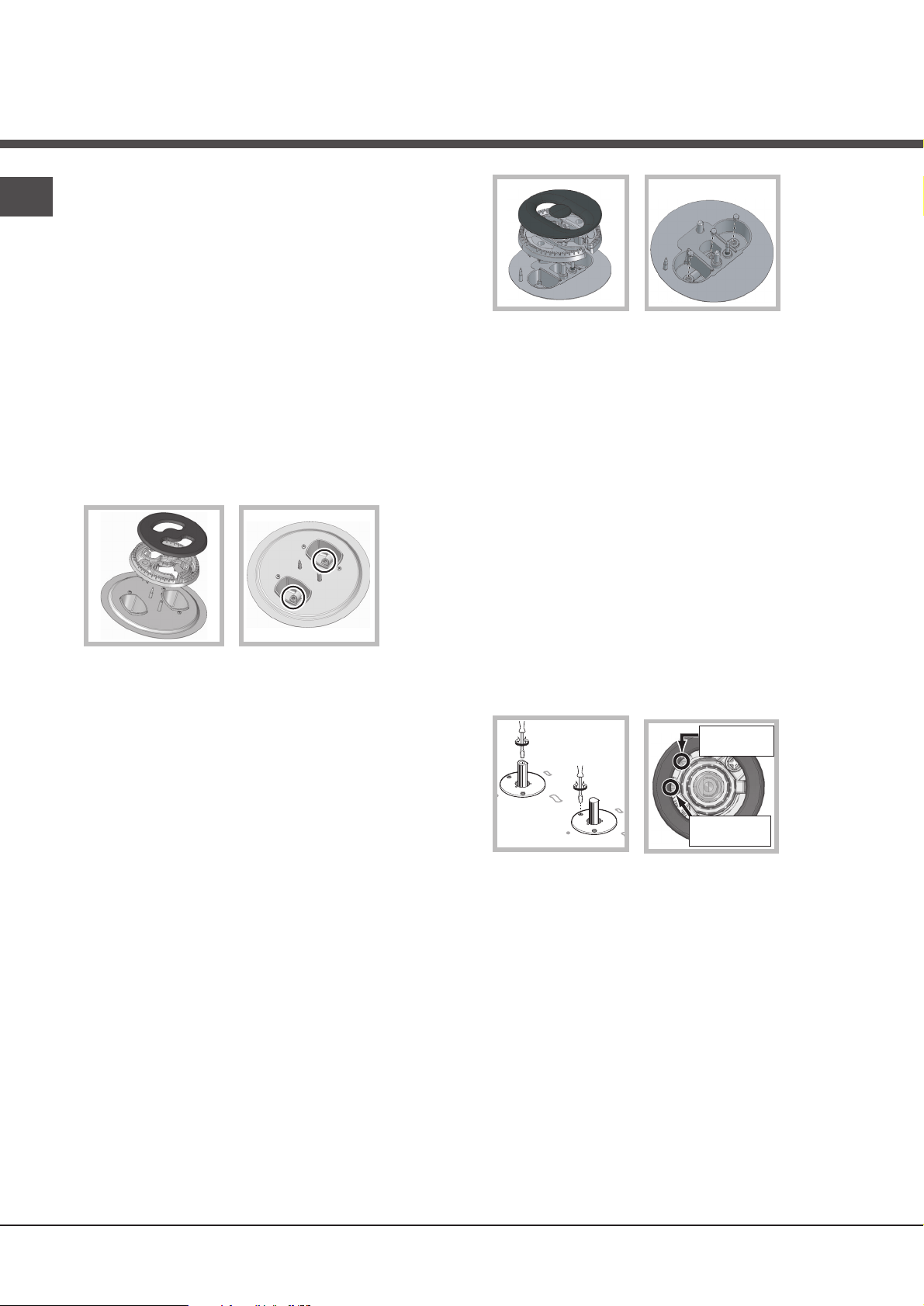
Replacing the nozzles on separate “double flame “
burners:
1. remove the grids and slide the burners from their
housings. The burner consists of 2 separate parts (
);
figure
see
PLEASE PHONE US TO REGISTER YOUR APPLIANCE AND ACTIVATE YOUR PARTS GUARANTEE ON 08448 24 24 24
3
GB
2. unscrew the burers with a 7 mm wrench spanner. The
internal burner has a nozzle, the external burner has
two (of the same size). Replace the nozzle with models
suited to the new type of gas (see table 1).
3. replace all the components by repeating the steps in
reverse order.
Replacing the Triple ring burner nozzles
1. Remove the pan supports and lift the burners out of
their housing. The burner consists of two separate parts
(see pictures).
2. Unscrew the nozzles using a 7 mm socket spanner.
Replace the nozzles with models that are configured
for use with the new type of gas (see Table 1). The two
nozzles have the same hole diameter.
3. Replace all the components by completing the above
operations in reverse order.
• Adjusting the burners’ primary air :
Does not require adjusting.
7. Minimum setting adjustment of the DRDA (DCDR)
burner with discrete adjustment and LED
visualisation:
• To adjust the outer ring, turn the knob anticlockwise to the minimum power position.
• To adjust the minimum power setting of the
inner ring, turn the knob clockwise to the minimum
power position.
• Remove the knob and intervene on the
adjustment screw located near the tap pin.
! If the appliance is connected to liquid gas, the regulation
screw must be fastened as tightly as possible.
! Once this procedure is finished, replace the old rating
sticker with one indicating the new type of gas used.
Stickers are available from any of our Service Centres.
! Should the gas pressure used be different (or vary
slightly) from the recommended pressure, a suitable
pressure regulator must be fitted to the inlet pipe (in order
to comply with current national regulations).
• Setting the burners to minimum:
1. Turn the tap to the low flame position.
2. Remove the knob and adjust the adjustment screw,
which is positioned in or next to the tap pin, until the
flame is small but steady.
! In the event of single-control DRDA (DCDR) burners,
adjustment can be performed by intervening on the 2
screws located near the tap pin
(see picture)
.
3. Having adjusted the flame to the required low setting,
while the burner is alight, quickly change the position of
the knob from minimum to maximum and vice versa
several times, checking that the flame does not go out.
4. Some appliances have a safety device (thermocouple)
fitted. If the device fails to work when the burners are
set to the low flame setting, increase this low flame
setting using the adjusting screw.
5. Once the adjustment has been made, replace the seals
on the by-passes using sealing wax or a similar
substance.
6. In the event of discrete-adjustment knobs with
LED visualisation, turn the knob to the minimum
power setting them remove it and intervene on the
adjustment screw located near the tap pin.
Total DRDA
(DCDR) burner
adjustment
Inner DRDA (DCDR)
burner adjustment
PLEASE PHONE US TO REGISTER YOUR APPLIANCE AND ACTIVATE YOUR PARTS GUARANTEE ON 08448 24 24 24
4
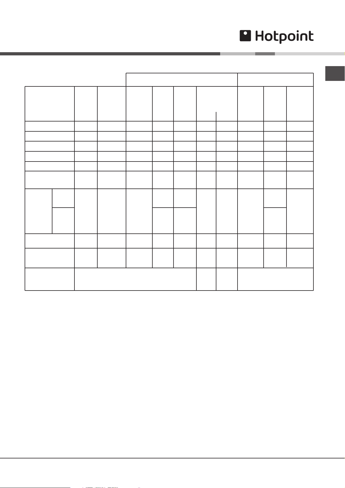
Burner and nozzle specifications (for 60 cm and 65 cm versions only)
Table 1 Liquid Gas Natural Gas
Burner Diameter Thermal Thermal By-pass Nozzle Flow* Thermal Nozzle Flow*
power power 1/100 1/100 (g/h) power 1/100 (l/h)
kW kW kW
(p.c.s.*) (p.c.s.*) (p.c.s.*)
(mm) Reduced Nominal (mm) (mm) *** ** Nominal (mm)
Fast (R)
100
0.70
3.00
39
86
218
214
3.00
132 (H)
286
GB
Reduced Fast (RR)
Semi Fast (S)
Auxiliary (A)
Triple Crown (TC)
Double flame
(DCDR internal) (1)
Double
flame (1)
Double Flame
(DCDR Internal) (2)
Double Flame
(DCDR External)
2 nozzle (2)
Supply pressures
(1) For single-control DRDA (DCDR) burner only
(2) For dual-control DRDA (DCDR) burner only
* At 15°C and 1013 mbar - dry gas
** Propane P.C.S. = 50.37 MJ/Kg
*** Butane P.C.S. = 49.47 MJ/Kg
Natural P.C.S. = 37.78 MJ/m³
(DCDR
internal)
(DCDR
external
2 nozzle)
100
75
55
130
30 0,30 0,90 27 44 65 64 0,90 74 86
130 1,50 3,60
30
130
0.70
0.40
0.40
1.50
0.40
1.50
Nominal (mbar)
Minimum (mbar)
Maximum (mbar)
2.60
1.65
1.00
3.30
0.90
3.60
39
28
28
61
27 44
55 60x2 100x 2
27
55
80
64
50
65x2
44
67x2
189
120
73
240
262 257 3,60
65
262
28-30
20
35
186
118
71
236
64
257
37
25
45
0.90
3.60
2.60
1.65
1.00
3.60
122 (H)
96 (Y)
79 (6)
103x2
74
74
100x2
248
157
95
343
343
86
343
20
17
25
PLEASE PHONE US TO REGISTER YOUR APPLIANCE AND ACTIVATE YOUR PARTS GUARANTEE ON 08448 24 24 24
5
 Loading...