

Hotpoint F 73 C.2 IX AUS User Manual
Operating Instructions
OVEN
GB
English,1
F 73 C.2 AUS
F 73 C.2 IX AUS
Contents
GB
Installation, 2-3
Positioning
Electrical connections
Data plate
Description of the appliance, 4
Overall view
Control panel
Start-up and use, 5
Starting the oven
Cooking modes, 6-8
Cooking modes
Practical cooking advice
Cooking advice table
The electronic cooking programmer, 9
Precautions and tips, 10
General safety
Disposal
Respecting and conserving the environment
Maintenance and care, 11
Switching the appliance off
Cleaning the appliance
Cleaning the oven door
Replacing the light bulb
Assistance, 12
Installation
560 m
m
.
45 mm.
GB
Before placing your new appliance into operation
please read these operating instructions carefully.
They contain important information for safe use, for
installation and for care of the appliance.
Please keep these operating instructions for future
reference. Pass them on to possible new owners of
the appliance.
Positioning
Keep packaging material out of the reach of
children.It can become a choking or suffocation
hazard. see Precautions and tips).
! The appliance must be installed by a qualified
person in compliance with the instructions provided.
Incorrect installation may cause harm to persons,
animals or may damage property.
Fitting the appliance
Use the appropriate cabinet to ensure that the
appliance functions properly.
The panels adjacent to the oven must be made of
heat-resistant material.
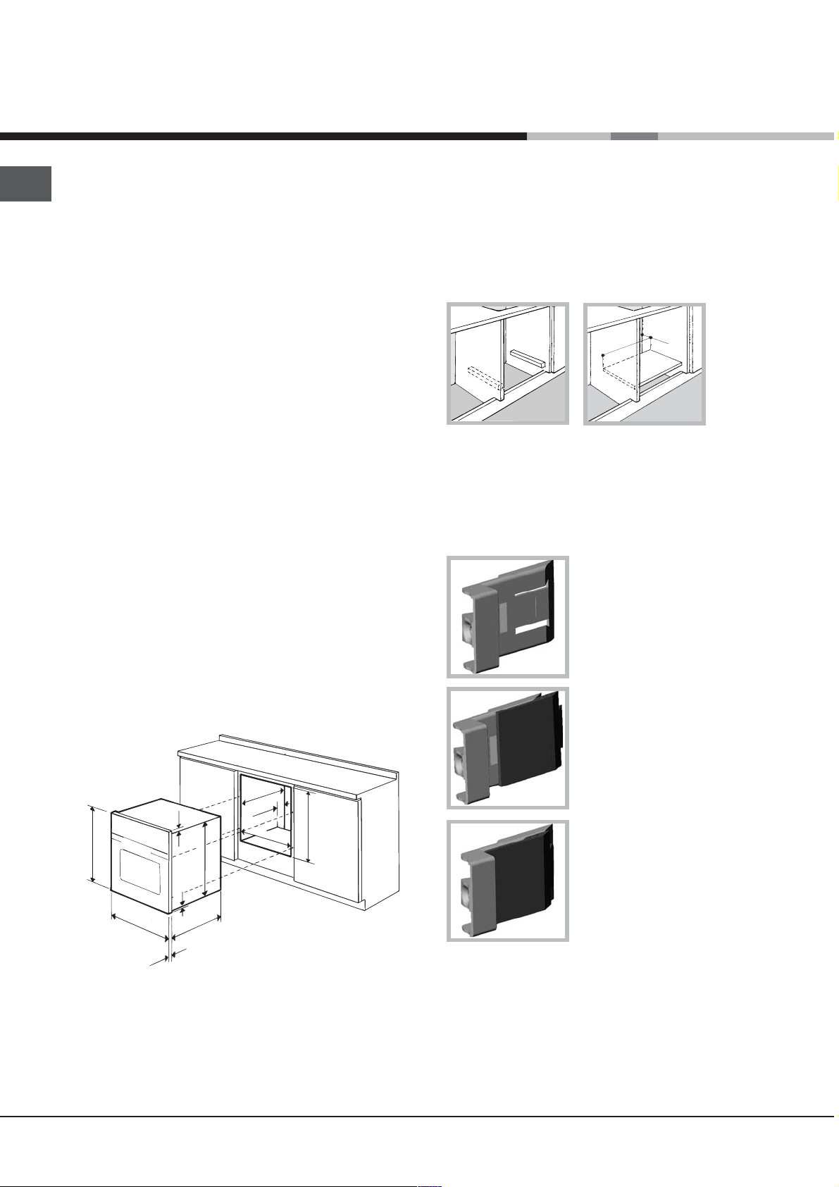
Ventilation
To ensure good ventilation, the back panel of the
cabinet must be removed. It is advisable to install the
oven so that it rests on two strips of wood, or on a
completely flat surface with an opening of at least 45 x
560 mm (see diagrams).
Centring and fastening
Position the 4 tabs on the side of the oven according
to the 4 holes of the outer frame. Adjust the tabs
according to the thickness of the cabinet side panel,
as shown below:
thickness of 20 mm: take off
the removable part of the tab
(see diagram)
Cabinets with a veneer exterior must be assembled
with glues which can withstand temperatures of up
to 100°C.
To install the oven under the counter (see diagram)
and in a kitchen unit, the cabinet must have the
following dimensions:
.
in
. m
m
m
7
4
5
567 mm.
45 mm.
558 mm.
593 mm.
23 mm.
595 mm.
5 mm.
595 mm.
545 mm.
24 mm.
! The appliance must not come into contact with
electrical parts once it has been installed.
The consumption indications on the data plate have
been calculated for this type of installation.
thickness of 18 mm: use the
first groove, which has already
been set in the factory (see
diagram)
thickness of 16 mm: use the
second groove (see diagram)
Secure the appliance to the cabinet by opening the
oven door and putting 4 screws into the 4 holes of the
outer frame.
! All parts which ensure the safe operation of the
appliance must not be removable without the aid of a
tool.
2
Electrical connections
! Ovens equipped with a three-pole power supply
cable are designed to operate with alternating
current at the voltage and frequency indicated on
the data plate located on the appliance (see below).
The voltage must be in the range between the
values indicated on the data plate (see below).
The socket is compatible with the plug of the
appliance. If the socket is incompatible with the
plug, ask an authorised technician to replace it. Do
not use extension cords or multiple sockets.
GB
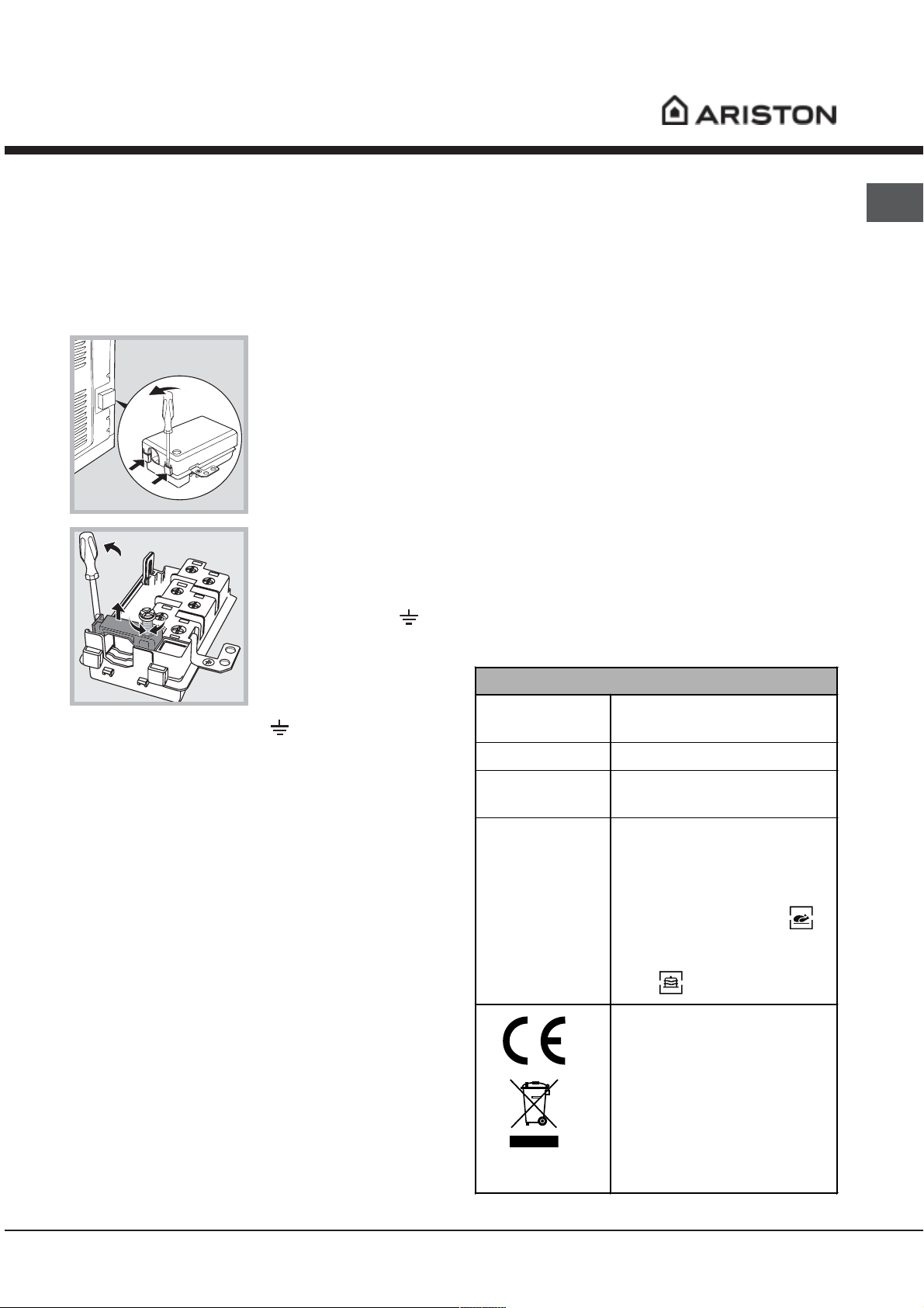
Fitting the power supply cable
1. Open the terminal
board by inserting a
screwdriver into the side
tabs of the cover. Use
the screwdriver as a
lever by pushing it down
to open the cover (see
diagram).
2. Loosen the cable
clamp screw and remove
it, using a screwdriver as
a lever (see figure).
3. Remove the wire
contact screws L-Nthen fasten the wires
under the screw heads,
respecting the colour
code: Blue (N), Brown (L)
and Yellow-Green Verde
(
).
Connecting the supply cable to the mains
Install a standardised plug corresponding to the
load indicated on the data plate (see side).
The appliance must be directly connected to the mains
using an omnipolar circuit-breaker with a minimum
contact opening of 3 mm installed between the
appliance and the mains, suitable for the load indicated
and complying with current electrical regulations (the
earthing wire must not be interrupted by the circuitbreaker). The supply cable must not come into contact
with surfaces with temperatures higher than 50°C.
! Once the appliance has been installed, the power
supply cable and the electrical socket must be
easily accessible.
! The cable must not be bent or compressed.
! The cable must be checked regularly and replaced
by authorised technicians only (see Assistance).
! The manufacturer declines any liability should
these safety measures not be observed.
,
DATA PLATE
width 43.5 cm
Dimensions
Volume
Electrical
connections
ENERGY LABEL
height 32 cm
depth 41.5 cm
58 l
voltage: 240V~ 50Hz
maximum power absorbed 2800W
(see data plate)
Directive 2002/40/EC on the label
of electric ovens.
Norm EN 50304
Energy consumption for Natural
convection – heating mode:
Traditional mode
Declared energy consumption for
Forced convection Class – heating
mode: Baking
! The installer must ensure that the correct electrical
connection has been made and that it is compliant
with safety regulations.
Before connecting to the power supply, make sure that:
The appliance is earthed and the plug is
compliant with the law.
The socket can withstand the maximum power of
the appliance, which is indicated on the data
plate (see below).
This appliance conforms to the
following European Economic
Community directives:
-2006/95/EEC of 12/12/06 (Low
Voltage) and subsequent
amendments;
- 89/336/EEC of 03/05/89
(Electromagnetic Compatibility) and
subsequent amendments;
- 93/68/EEC of 22/07/93 and
subsequent amendments.
- 2002/96/EC
3
Description of the appliance
GB
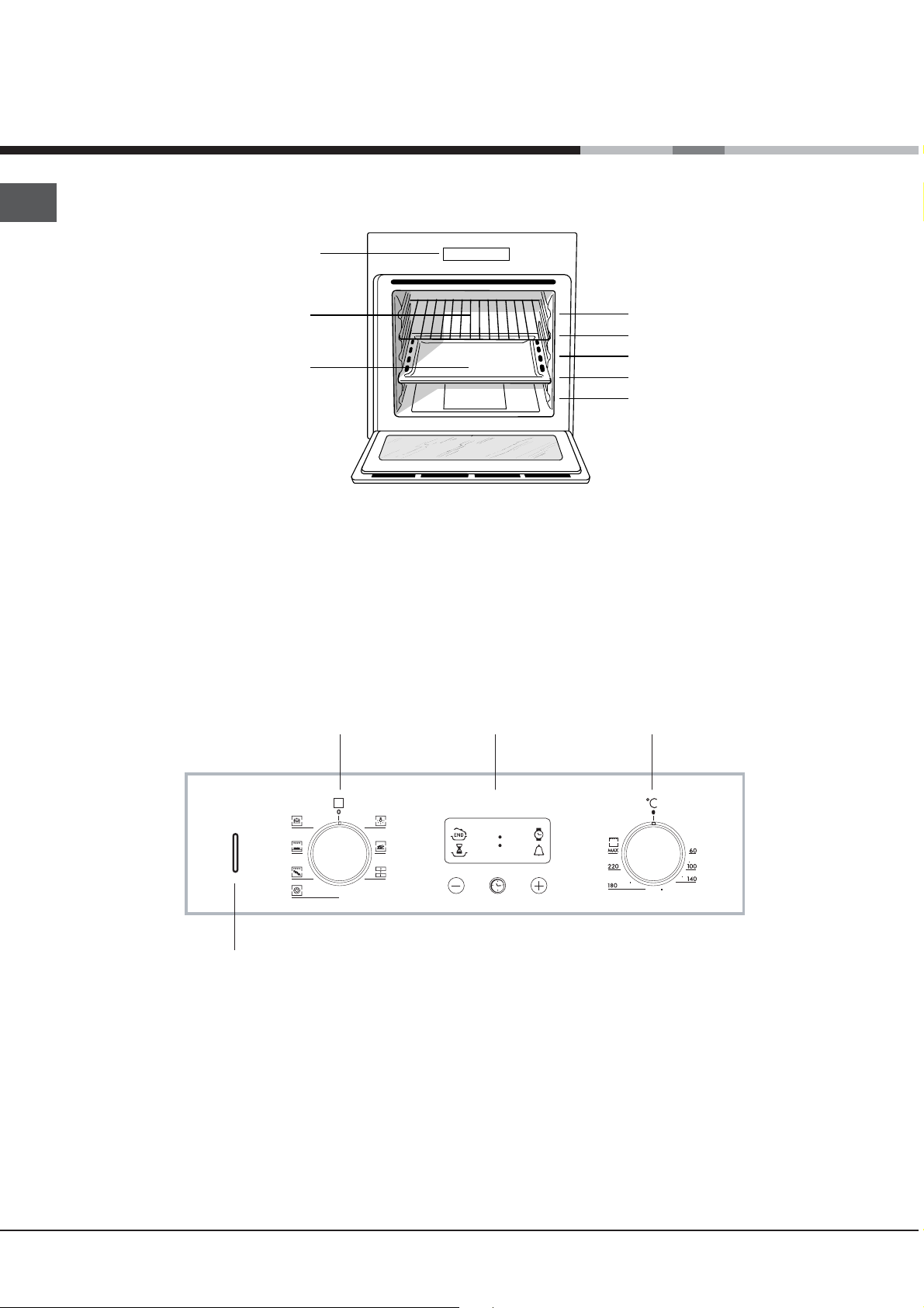
Overall view
Control panel
GRILL
DRIPPING PAN
GUIDES for the
sliding racks
position 5
position 4
position 3
position 2
position 1
Control panel
THERMOSTAT
indicator light
SELECTOR
Knob
ELECTRONIC
Programmer
•• ••
THERMOSTAT
Knob
4
 Loading...