

Page 1
Istruzioni per luso
IT
Italiano, 1 English,17
CPDO902 X I/HA
GB
CUCINA E FORNO
IT
Sommario
Installazione, 2-5
Posizionamento e livellamento
Collegamento elettrico
Collegamento gas
Adattamento a diversi tipi di gas
Tabella caratteristiche bruciatori e ugelli
Tabella caratteristiche
Descrizione dellapparecchio, 6
Vista dinsieme
Pannello di controllo
Avvio e utilizzo, 7-13
Uso del piano cottura
Uso del forno (1° forno)
Programmi di cottura (1° forno)
Consigli pratici di cottura (1° forno)
Uso del forno (2° forno)
Programmi di cottura (2° forno)
Consigli pratici di cottura (2° forno)
Programmatore (1° forno)
Tabella cottura in forno multifunzione (1° FORNO)
Tabella cottura in forno elettrico (2° FORNO)
Consigli pratici di cottura
Tabella cottura in forno
Precauzioni e consigli, 14
Sicurezza generale
Smaltimento
Risparmiare e rispettare lambiente
Manutenzione e cura, 15
Escludere la corrente elettrica
Pulire lapparecchio
Sostituire la lampadina di illuminazione del forno
Manutenzione rubinetti gas
Assistenza, 16
Assistenza attiva 7 giorni su 7
Page 2
Installazione
IT
È importante conservare questo libretto per poterlo
consultare in ogni momento. In caso di vendita, di
cessione o di trasloco, assicurarsi che resti insieme
allapparecchio.
Leggere attentamente le istruzioni: ci sono
importanti informazioni sullinstallazione, sulluso e
sulla sicurezza.
Linstallazione dellapparecchio va effettuata
secondo queste istruzioni da personale qualificato.
Qualsiasi intervento di regolazione o manutenzione
deve essere eseguito con la cucina disinserita
dallimpianto elettrico.
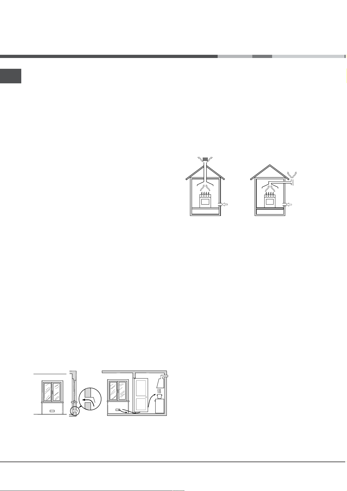
Ventilazione dei locali
Lapparecchio può essere installato solo in locali
permanentemente ventilati, secondo le norme UNICIG 7129 e 7131 e successivi aggiornamenti in vigore.
Nel locale in cui viene installato lapparecchio deve
poter affluire tanta aria quanta ne viene richiesta
dalla regolare combustione del gas (la portata di aria
non deve essere inferiore a 2 m
potenza installata).
Le prese di immisione aria, protette da griglie,
devono avere un condotto di almeno 100 cm
sezione utile ed essere collocate in modo da non
poter essere ostruite, neppure parzialmente (vedi
figura A).
Tali prese devono essere maggiorate nella misura
del 100% con un minimo di 200 cm
piano di lavoro dellapparecchio sia privo del
dispositivo di sicurezza per assenza di fiamma e
quando lafflusso dellaria avviene in maniera
indiretta da locali adiacenti (vedi figura B) purché
non siano parti comuni dellimmobile, ambienti con
pericolo di incendio o camere da letto dotati di un
condotto di ventilazione con lesterno come descritto
sopra.
A B
3
/h per kW di
2
di
2
qualora il
Locale adiacente Locale da ventilare
Dopo un uso prolungato dellapparecchio, è
consigliabile aprire una finestra o aumentare la
velocità di eventuali ventilatori.
Scarico dei fumi della combustione
Lo scarico dei fumi della combustione deve essere
assicurato tramite una cappa collegata a un camino
a tiraggio naturale di sicura efficienza, oppure
mediante un elettroventilatore che entri
automaticamente in funzione ogni volta che si
accende lapparecchio (vedi figure).
Scarico direttamente Scarico tramite camino o
allesterno canna fumaria ramificata
(riservata agli apparecchi
di cottura)
I gas di petrolio liquefatti, più pesanti dellaria,
ristagnano in basso, perciò i locali contenenti bidoni
di GPL devono prevedere aperture verso lesterno
per levacuazione dal basso di eventuali fughe di
gas.
I bidoni di GPL, vuoti o parzialmente pieni, non
devono essere installati o depositati in locali o vani a
livello più basso del suolo (cantinati, ecc.). Tenere
nel locale solo il bidone in utilizzo, lontano da
sorgenti
di calore (forni, camini, stufe) capaci di portarlo
a temperature superiori ai 50°C.
Posizionamento e livellamento
È possibile installare lapparecchio di fianco a
mobili che non superino in altezza il piano di lavoro.
A
Apertura di ventilazione Maggiorazione della
per laria comburente fessura fra porta e
pavimento
2
Assicurarsi che la parete a contatto con il retro
dellapparecchio sia di materiale non infiammabile e
resistente al calore (T 90°C).
Per una corretta installazione:
porre lapparecchio in cucina, in sala da pranzo o
in un monolocale (non in bagno);
se il piano della cucina è più alto di quello dei
mobili, essi devono essere posti ad almeno 600
mm dallapparecchio;
Page 3
se la cucina viene
installata sotto un
pensile, esso dovrà
mantenere una
distanza minima dal
mm. with hood
mm. without hood
piano di 420 mm.
420
650
700
Tale distanza deve
Min. mm.
min.
min.
mm.
420
Min.
HOOD
Min. mm.
900
essere di 700 mm se i
pensili sono
infiammabili (vedi
figura);
non posizionare tende dietro la cucina o a meno di
200 mm dai suoi lati;
eventuali cappe devono essere installate secondo
le indicazioni del relativo libretto di istruzione.
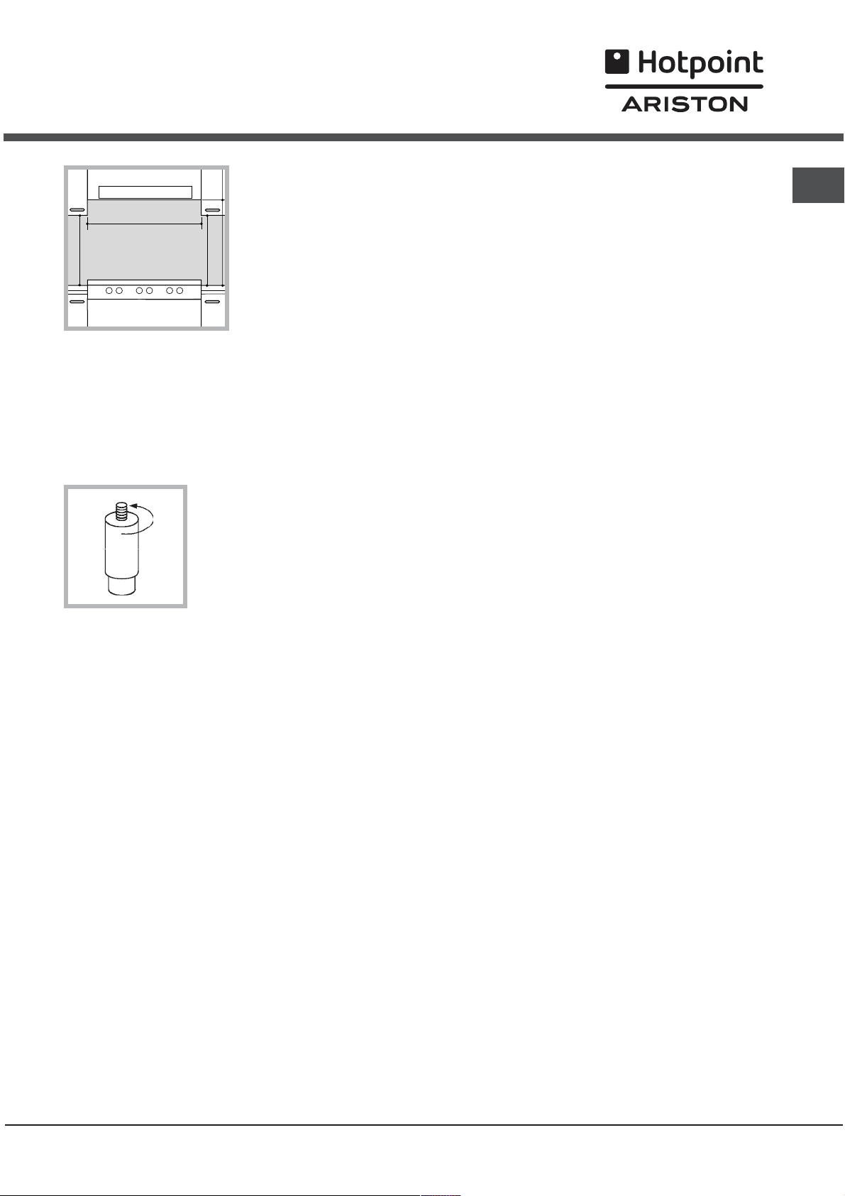
Livellamento
Se è necessario livellare
lapparecchio, avvitare i
piedini di regolazione forniti in
dotazione nelle apposite sedi
poste negli angoli alla base
della cucina (vedi figura).
Collegamento elettrico
raggiungibili.
IT
Il cavo non deve subire piegature o compressioni.
Il cavo deve essere controllato periodicamente e
sostituito solo da tecnici autorizzati.
Lazienda declina ogni responsabilità qualora
queste norme non vengano rispettate.
Collegamento gas
Il collegamento alla rete del gas o alla bombola del
gas può essere effettuato con un tubo flessibile in
gomma o in acciaio, secondo le norme UNI-CIG 7129
e 7131 e successivi aggiornamenti in vigore e dopo
essersi accertati che lapparecchio sia regolato per il
tipo di gas con cui sarà alimentato (vedi etichetta di
taratura sul coperchio: in caso contrario vedi sotto).
Nel caso di alimentazione con gas liquido da
bombola, utilizzare regolatori di pressione conformi
alle norme UNI EN 12864 e successivi aggiornamenti in
vigore. Per facilitare lallacciamento, lalimentazione
del gas è orientabile lateralmente*: invertire il
portagomma per il collegamento con il tappo di
chiusura e sostituire la guarnizione di tenuta fornita
in dotazione.
Montare sul cavo una spina normalizzata per il
carico indicato nella targhetta caratteristiche posta
sullapparecchio (vedi tabella Dati tecnici).
In caso di collegamento diretto alla rete è necessario
interporre tra lapparecchio e la rete un interruttore
onnipolare con apertura minima fra i contatti di 3
mm, dimensionato al carico e rispondente alle norme
nazionali in vigore (il filo di terra non deve essere
interrotto dallinterruttore). Il cavo di alimentazione
deve essere posizionato in modo tale che in nessun
punto superi di 50°C la temperatura ambiente.
Prima di effettuare lallacciamento accertarsi che:
la presa abbia la messa a terra e sia a norma di
legge;
la presa sia in grado di sopportare il carico
massimo di potenza della macchina, indicato
della targhetta caratteristiche;
la tensione di alimentazione sia compresa nei
valori nella targhetta caratteristiche;
la presa sia compatibile con la spina
dellapparecchio. In caso contrario sostituire la
presa o la spina; non usare prolunghe e multiple.
Ad apparecchio installato, il cavo elettrico e la
presa della corrente devono essere facilmente
Per un sicuro funzionamento, per un adeguato uso
dellenergia e per una maggiore durata
dellapparecchio, assicurarsi che la pressione di
alimentazione rispetti i valori indicati nella tabella
Caratteristiche bruciatori e ugelli (vedi sotto).
Allacciamento gas con tubo flessibile in gomma
Verificare che il tubo risponda alle norme UNI-CIG
7140 in vigore. Il diametro interno del tubo deve
essere: 8 mm per alimentazione con gas liquido; 13
mm per alimentazione con gas metano.
Effettuato lallacciamento assicurarsi che il tubo:
non sia in nessun punto a contatto con parti che
raggiungono temperature superiori a 50°C;
non sia soggetto ad alcuno sforzo di trazione e di
torsione e non presenti pieghe o strozzature;
non venga a contatto con corpi taglienti, spigoli
vivi, parti mobili e non sia schiacciato;
sia facilmente ispezionabile lungo tutto il percorso
per poter controllare il suo stato di conservazione;
abbia una lunghezza inferiore a 1500 mm;
sia ben calzato alle sue due estremità, dove va
fissato con fascette di serraggio conformi alle
norme UNI-CIG 7141 in vigore.
3
Page 4
IT
Se una o più di queste condizioni non può essere
rispettata o se la cucina viene installata secondo le
condizioni della classe 2 - sottoclasse 1
(apparecchio incassato tra due mobili), bisogna
ricorrere al tubo flessibile in acciaio (vedi sotto).
Allacciamento gas con tubo flessibile in acciaio
inossidabile a parete continua con attacchi
filettati
Verificare che il tubo sia conforme alle norme UNICIG 9891 e le guarnizioni di tenuta metalliche in
alluminio conformi alla UNI 9001-2 o guarnizioni in
gomma conformi alla UNI EN 549.
Per mettere in opera il tubo eliminare il portagomma
presente sullapparecchio (il raccordo di entrata del
gas allapparecchio è filettato 1/2 gas maschio
cilindrico).
Effettuare lallacciamento in modo che la lunghezza
della tubatura non superi i 2 metri di estensione
massima, e assicurarsi che il tubo non venga a
contatto con parti mobili e non sia schiacciato.
Controllo tenuta
A installazione ultimata, controllare la perfetta tenuta
di tutti i raccordi utilizzando una soluzione saponosa
e mai una fiamma.
Adattamento a diversi tipi di gas
3. rimettere in posizione tutti i componenti seguendo
le operazioni inverse rispetto alla sequenza di cui
sopra.
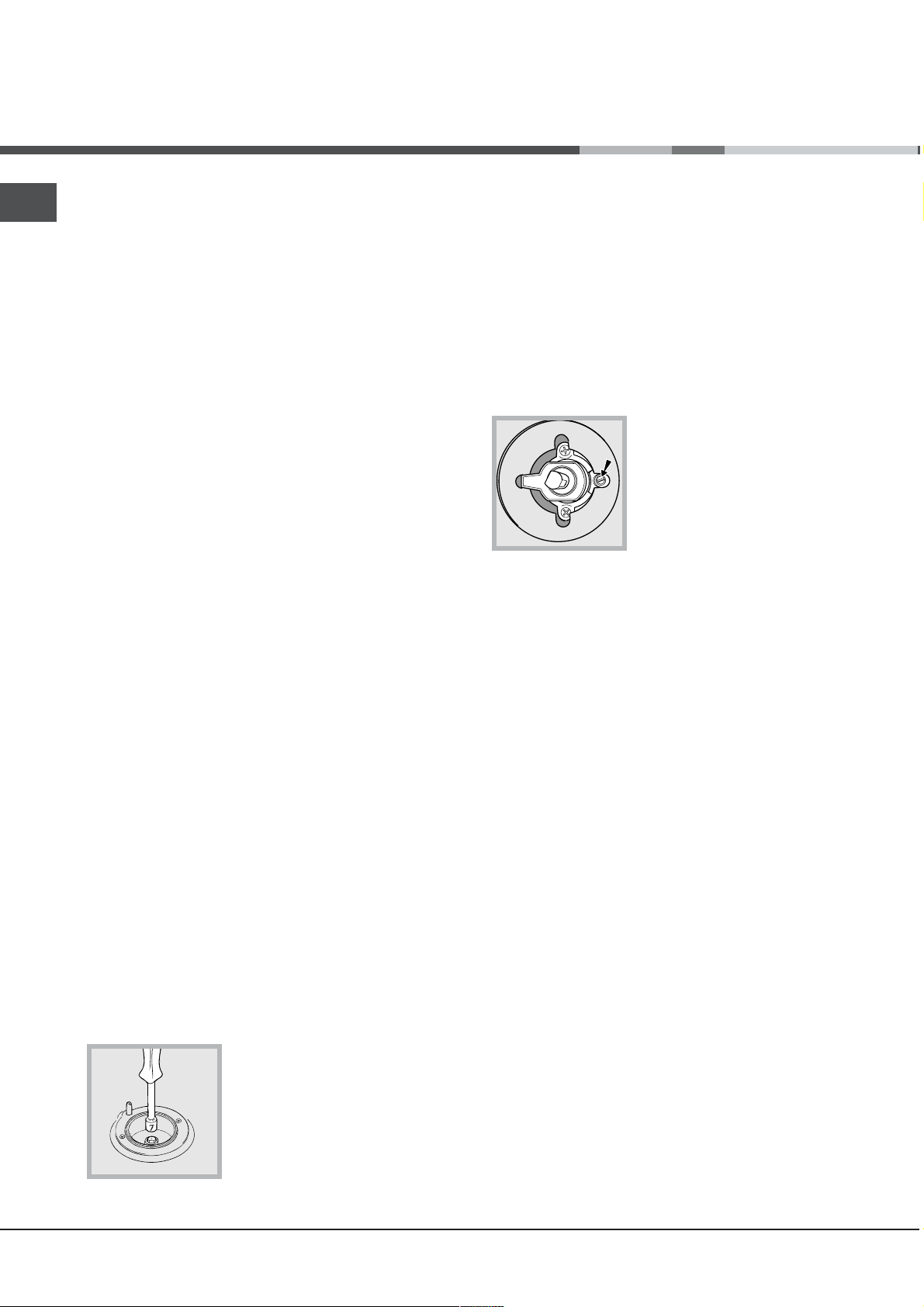
Regolazione del minimo dei bruciatori del piano:
1. portare il rubinetto sulla posizione di minimo;
2. togliere la manopola e agire sulla vite di
regolazione posta allinterno o di fianco allastina del
rubinetto fino a ottenere una piccola fiamma
regolare.
Nel caso dei gas liquidi, la vite di regolazione
dovrà essere avvitata a fondo;
3. verificare che, ruotando rapidamente il rubinetto
dalla posizione di massimo a quella di minimo, non
si abbiano spegnimenti del bruciatore.
I bruciatori del piano non necessitano di
regolazione dellaria primaria.
Dopo la regolazione con un gas diverso da quello
di collaudo, sostituire la vecchia etichetta di taratura
con quella corrispondente al nuovo gas, reperibile
presso i Centri Assistenza Tecnica Autorizzata.
È possibile adattare lapparecchio a un tipo di gas
diverso da quello per il quale è predisposto (indicato
sulletichetta di taratura sul coperchio).
Adattamento del piano cottura
Sostituzione degli ugelli dei bruciatori del piano:
1. togliere le griglie e sfilare i bruciatori dalle loro
sedi;
2. svitare gli ugelli, servendosi di una chiave a tubo
da 7 mm (vedi figura), e sostituirli con quelli adatti al
nuovo tipo di gas (vedi tabella Caratteristiche
bruciatori e ugelli);
Qualora la pressione del gas sia diversa (o
variabile) da quella prevista, è necessario installare
sulla tubazione dingresso un regolatore di
pressione, secondo le norme EN 88-1 e EN88-2 in
vigore per i regolatori per gas canalizzati.
4
Page 5
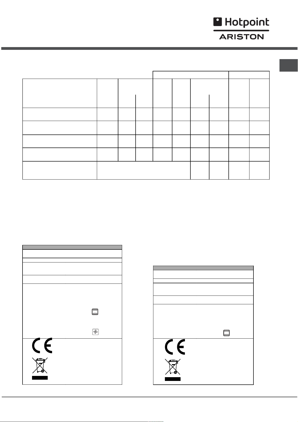
Tabella caratteristiche bruciatori e ugelli
Tabella 1 Gas liquido Gas naturale
Diametro
(mm)
BRUCIATORE
Potenza termica
kW (H.s.*)
By-pass
1/100
Ugello
1/100
Portata *
g/h
Ugello
1/100
Portata *
IT
l/h
Nomin. Ridot. *** **
(mm)
(mm)
(mm)
Rapido 100 3.00 0.7 40 86 218 214 116 286
Semirapido 75 1.65 0.4 30 64 120 118 96 157
Ausiliario 55 1.00 0.4 30 50 73 71 71 95
Tripla Corona 130 3.25 1.3 57 91 236 232 124 309
Pressioni di alimentazione
Nominale (mbar)
Minima (mbar)
Massima (mbar)
28-30
20
35
37
25
45
* A 15°C e 1013 mbar-gas secco
** Propano P.C.S. = 50.37 MJ/Kg
*** Butano P.C.S. = 49.47 MJ/Kg
Naturale P.C.S. = 37.78 MJ/m
TABELLA CARATTERISTICHE
Dimensioni Forno
HxLxP
Volume
Bruciatori
Tensione e frequenza
d'alimentazione
ENERGY LABEL
(1° Fo rno)
H:34;W:38;D:44 cm
54 Lt
adattabili a tutti i tipi di gas
indica ti nella targhetta
caratteristiche
vedi targhetta caratteristiche
Direttiva 2002/40/CE
sulletichetta dei fo rni elettrici.
Norma EN 50 304
Consumo energia convezione
Naturale – funzione di
riscaldamento : Tradizionale;
Consumo energia dichiarazione
Classe convezione Forzata funzione di
riscaldamento : Multicottura.
Direttive Comunitarie:
2006/95/CEE del 12/12/06
(Bas sa Tensione) e successive
modificazioni - 89/336/CEE del
03/05/89 (Compatibilità
Elettromagnetica) e succ essive
modificazioni - 90/369/CEE del
29/06/90 (Gas) e successive
modificazioni -93/68/CEE del
22/07/93 e successive
modificazioni - 2002/96/EC.
3
TABELLA CARATTERISTICHE (2° Forno)
Dim ensioni Forno
HxLxP
Volume
Bruciatori
Tensione e frequenza
d'alim entazione
ENERGY LABEL
33.8x24.5x43.8 cm
36 l
adattabili a tutti i tipi di gas
indicati nella ta rg h etta
caratteristiche
vedi targhetta caratteristiche
Direttiva 2002/40/CE
sulle tichetta dei fo rn i elettrici.
Norma EN 50304
Consumo energia convezione
Naturale – funzione di
riscaldamento: Tradizionale;
Direttive Comunitarie:
2006/95/CEE del 12/12/06
(Bassa Tensione) e successive
modificazioni - 89/336/CEE del
03/05/89 (Compatibilità
Elettromagnetica) e successive
modificazioni - 90/369/CEE del
29/06/90 (Gas) e successive
modificazioni -93/6 8/C EE del
22/07/93 e successive
modificazioni - 2002/96/EC.
20
17
25
5
Page 6
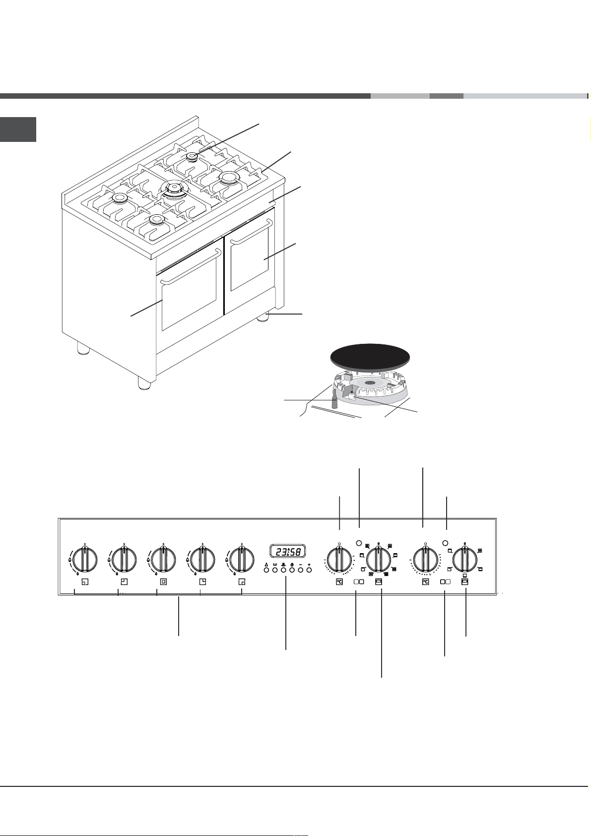
Descrizione
dellapparecchio
IT
Vista dinsieme
1° Forno
Bruciatore a gas
DISPOSITIVO DI
SICUREZZA
Griglia del piano di lavoro
Pannello di controllo
2° Forno
Piedini regolabili
Candela di accensione dei
BRUCIATORI GAS
Pannello di controllo
TERMOSTATO (1° Forno)
TERMOSTATO (1° Forno)
Manopole BRUCIATORI
del piano cottura
• BRUCIATORI GAS sono di diverse dimensioni e
potenze. Scegliete quello più adatto al diametro
del recipiente da utilizzare.
• Manopole di comando dei BRUCIATORI GAS per
la regolazione della fiamma.
• Candela di accensione dei BRUCIATORI GAS*
permette laccensione automatica del bruciatore
prescelto.
PROGRAMMATORE
(FORNO ELETTRICO - 1°
Forno)
Manopola
MAX
200
1° Forno
PROGRAMMI
Spia
50
100
150
Manopola
(1° Forno)
Manopola
TERMOSTATO (2° Forno)
Spia
TERMOSTATO (2° Forno)
MAX
50
100
200
150
2° Forno
Manopola
PROGRAMMI
(2° Forno)
6
Page 7
Avvio e utilizzo
Uso del piano cottura
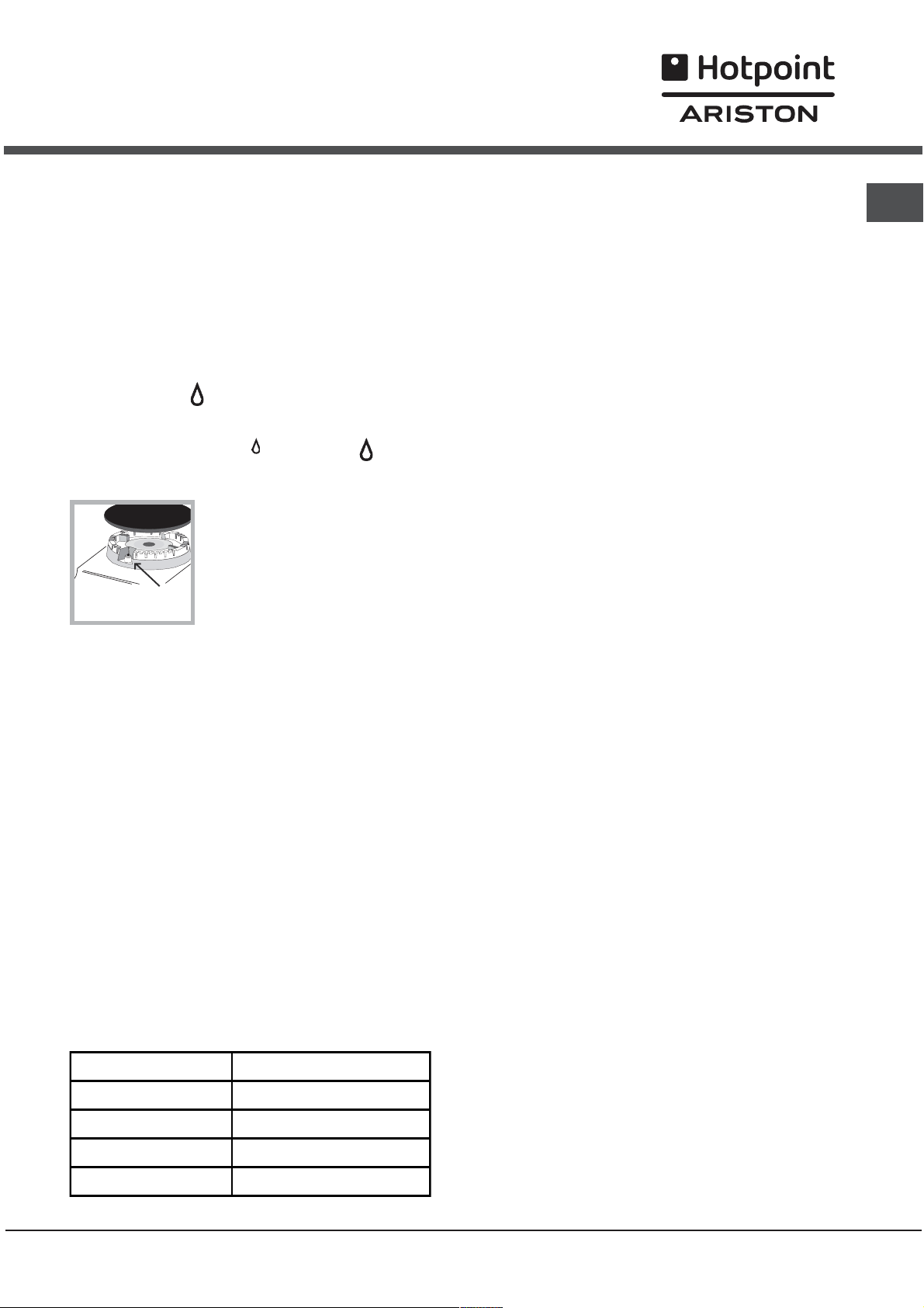
Accensione dei bruciatori
In corrispondenza di ogni manopola BRUCIATORE è
indicato con un cerchietto pieno il bruciatore
associato.
Per accendere un bruciatore del piano cottura:
1. avvicinare al bruciatore una fiamma o un
accendigas;
2. premere e contemporaneamente ruotare in senso
antiorario la manopola BRUCIATORE sul simbolo di
fiamma massima
3. regolare la potenza della fiamma desiderata,
ruotando in senso antiorario la manopola
BRUCIATORE: sul minimo
una posizione intermedia.
accensione avvenuta. Può accadere che il bruciatore
si spenga al momento del rilascio della manopola. In
questo caso, ripetere loperazione tenendo premuta
la manopola più a lungo.
In caso di estinzione accidentale delle fiamme,
spegnere il bruciatore e aspettare almeno 1 minuto
prima di ritentare laccensione.
Se lapparecchio è dotato di dispositivo di
sicurezza* per assenza di fiamma, tenere premuta la
manopola BRUCIATORE circa 2-3 secondi per
mantenere accesa la fiamma e per attivare il
dispositivo.
Per spegnere il bruciatore ruotare la manopola fino
allarresto .
Consigli pratici per luso dei bruciatori
Per un miglior rendimento dei bruciatori e un
consumo minimo di gas occorre usare recipienti a
fondo piatto, provvisti di coperchio e proporzionati al
bruciatore:
Bruciatore ø Diametro Recipienti (cm)
Rapido (R) 24 - 26
Semi Rapido (S) 16 - 22
Ausiliario (A) 10 - 14
Tripla Corona (TC) 24 - 26
.
, sul massimo o su
Se lapparecchio è dotato di
accensione elettronica (vedi
figura) è sufficiente premere e
contemporaneamente ruotare in
senso antiorario la manopola
BRUCIATORE sul simbolo di
fiamma massima, fino ad
Per identificare il tipo di bruciatore fate riferimento ai
disegni presenti nel paragrafo "Caratteristiche dei
bruciatori ed ugelli".
Evitare che le pentole fuoriescano dai bordi del
piano durante luso.
Sui modelli dotati di griglietta di riduzione,
questultima dovrà essere utilizzata solo per il
bruciatore ausiliario, quando si utilizzano dei
recipienti di diametro inferiore a 12 cm.
Uso del forno (1° Forno)
Prima dell'uso, togliere tassativamente le pellicole
in plastica poste ai lati dell'apparecchio
Alla prima accensione fare funzionare il forno a
vuoto per almeno unora con il termostato al
massimo e a porta chiusa. Poi spegnere, aprire la
porta del forno e aerare il locale. Lodore che si
avverte è dovuto allevaporazione delle sostanze
usate per proteggere il forno.
! Non appoggiare mai oggetti sul fondo del forno
perché si rischiano danni allo smalto.
1. Selezionare il programma di cottura desiderato
ruotando la manopola PROGRAMMI.
2. Scegliere la temperatura ruotando la manopola
TERMOSTATO. Una lista con le cotture e le relative
temperature consigliate è consultabile nella Tabella
cottura (vedi Programmi).
3. La spia TERMOSTATO accesa indica la fase di
riscaldamento fino alla temperatura impostata.
4. Durante la cottura è sempre possibile:
- modificare il programma di cottura agendo sulla
manopola PROGRAMMI;
- modificare la temperatura agendo sulla manopola
TERMOSTATO;
- interrompere la cottura riportando la manopola
PROGRAMMI in posizione 0.
! Porre sempre i recipienti di cottura sulla griglia in
dotazione.
Spia TERMOSTATO
La sua accensione segnala che il forno sta
producendo calore. Si spegne quando allinterno
viene raggiunta la temperatura selezionata. A questo
punto la spia si accende e si spegne
alternativamente, indicando che il termostato è in
funzione e mantiene costante la temperatura.
Luce del forno
Si accende ruotando la manopola PROGRAMMI in
IT
7
Page 8
IT
qualsiasi posizione diversa da 0 e resta accesa
finché il forno è in funzione. Selezionando
manopola, la luce si accende senza attivare alcun
elemento riscaldante.
Ventilazione di raffreddamento
Per ottenere una riduzione delle temperature esterne,
una ventola di raffreddamento genera un getto daria
che esce tra il pannello di controllo e la porta del
forno.
! A fine cottura la ventola rimane attiva finché il forno
non è sufficientemente freddo.
8
con la
Programmi di cottura (1° FORNO)
Per tutti i programmi è impostabile una temperatura
tra 50°C e MAX, tranne:
MAXI-GRILL/MINI-GRILL (si consiglia di impostare
solo su MAX);
Programma MULTICOTTURA
Si attivano tutti gli elementi riscaldanti (superiore, inferiore
e circolare) ed entra in funzione la ventola. Poiché il calore
è costante in tutto il forno, laria cuoce e rosola il cibo in
modo uniforme. È possibile utilizzare fino a un massimo di
due ripiani contemporaneamente.
Programma MINI-GRILL
Si attiva la parte centrale dellelemento riscaldante
superiore. La temperatura elevata e diretta del grill è
consigliata per gli alimenti che necessitano di unalta
temperatura superficiale (bistecche di vitello e di manzo,
filetto, entrecote). È un programma dai consumi contenuti,
ideale per grigliare piatti di ridotte dimensioni. Posizionare
il cibo al centro della griglia, poiché negli angoli non viene
cotto.
Programma MAXI-GRILL
Si attiva lintero elemento riscaldante superiore.
GRATIN (si consiglia di non superare la temperatura di
200°C).
Programma FORNO TRADIZIONALE
Si attivano i due elementi riscaldanti inferiore e superiore.
Con questa cottura tradizionale è meglio utilizzare un solo
ripiano: con più ripiani si ha una cattiva distribuzione della
temperatura.
Programma FORNO PASTICCERIA
Si attiva lelemento riscaldante posteriore ed entra in
funzione la ventola, garantendo un calore delicato e
uniforme allinterno del forno. Questo programma è
indicato per la cottura dei cibi delicati (ad es. dolci che
necessitano di lievitazione) e preparazioni mignon su tre
ripiani contemporaneamente.
Z Programma FORNO PIZZA
Si attivano gli elementi riscaldanti inferiore e circolare ed
entra in funzione la ventola. Questa combinazione
consente un rapido riscaldamento del forno, con un forte
apporto di calore in prevalenza dal basso. Nel caso si
utilizzi più di un ripiano alla volta, è necessario cambiarli di
posizione tra loro a metà cottura.
Programma GRATIN
e
Si attiva lelemento riscaldante superiore ed entrano in
funzione la ventola e il girarrosto (ove presente). Unisce
allirradiazione termica unidirezionale, la circolazione
forzata dellaria allinterno del forno. Ciò impedisce la
bruciatura superficiale degli alimenti aumentando il potere
di penetrazione del calore.
Le cotture GRILL e GRATIN debbono essere effettuate a
porta chiusa.
Consigli pratici di cottura (1° FORNO)
Nelle cotture ventilate non utilizzare le posizioni dei ripiani
1 e 5: sono investite direttamente dallaria calda, che
potrebbe provocare bruciature sui cibi delicati.
MULTICOTTURA
Utilizzare le posizioni dei ripiani 2 e 4, mettendo alla 2 i
cibi che richiedono maggior calore.
Disporre la leccarda in basso e la griglia in alto.
GRILL
Nelle cotture GRILL mettere la griglia in posizione 2 o 3
e la leccarda in posizione 1 per raccogliere i residui di
cottura (sughi e/o grassi). Nella cottura GRATIN
mettere la griglia in posizione 2 o 3 e la leccarda in
posizione 1 per raccogliere i residui di cottura.
8
Page 9
Si consiglia di impostare il livello di energia al massimo.
Non allarmarsi se la resistenza superiore non resta
costantemente accesa: il suo funzionamento è
controllato da un termostato.
FORNO PIZZA
Utilizzare una teglia in alluminio leggero,
appoggiandola sulla griglia in dotazione.
Con la leccarda si allungano i tempi di cottura
e difficilmente si ottiene una pizza croccante.
Nel caso di pizze molto farcite è consigliabile inserire la
mozzarella a metà cottura.
Uso del forno (2° Forno)
Prima dell'uso, togliere tassativamente le pellicole
in plastica poste ai lati dell'apparecchio
Alla prima accensione fare funzionare il forno a
vuoto per almeno unora con il termostato al
massimo e a porta chiusa. Poi spegnere, aprire la
porta del forno e aerare il locale. Lodore che si
avverte è dovuto allevaporazione delle sostanze
usate per proteggere il forno.
! Non appoggiare mai oggetti sul fondo del forno
perché si rischiano danni allo smalto.
1. Selezionare il programma di cottura desiderato
ruotando la manopola PROGRAMMI.
2. Scegliere la temperatura ruotando la manopola
TERMOSTATO. Una lista con le cotture e le relative
temperature consigliate è consultabile nella Tabella
cottura (vedi Programmi).
3. La spia TERMOSTATO accesa indica la fase di
riscaldamento fino alla temperatura impostata.
4. Durante la cottura è sempre possibile:
- modificare il programma di cottura agendo sulla
manopola PROGRAMMI;
- modificare la temperatura agendo sulla manopola
TERMOSTATO;
- interrompere la cottura riportando la manopola
PROGRAMMI in posizione 0.
! Porre sempre i recipienti di cottura sulla griglia in
dotazione.
Spia TERMOSTATO
Luce del forno
Si accende ruotando la manopola PROGRAMMI in
qualsiasi posizione diversa da 0 e resta accesa
finché il forno è in funzione. Selezionando
manopola, la luce si accende senza attivare alcun
elemento riscaldante.
8
con la
Programmi di cottura (2° FORNO)
Per tutti i programmi è impostabile una temperatura
tra 50°C e MAX, tranne:
MAXI-GRILL/MINI-GRILL (si consiglia di impostare
solo su MAX);
Programma FORNO TRADIZIONALE
Si attivano i due elementi riscaldanti inferiore e superiore.
Con questa cottura tradizionale è meglio utilizzare un solo
ripiano: con più ripiani si ha una cattiva distribuzione della
temperatura.
Programma FORNO PASTICCERIA
Si attiva lelemento riscaldante posteriore ed entra in
funzione la ventola, garantendo un calore delicato e
uniforme allinterno del forno. Questo programma è
indicato per la cottura dei cibi delicati (ad es. dolci che
necessitano di lievitazione) e preparazioni mignon su tre
ripiani contemporaneamente.
Programma MINI-GRILL
Si attiva la parte centrale dellelemento riscaldante
superiore. La temperatura elevata e diretta del grill è
consigliata per gli alimenti che necessitano di unalta
temperatura superficiale (bistecche di vitello e di manzo,
filetto, entrecote). È un programma dai consumi contenuti,
ideale per grigliare piatti di ridotte dimensioni. Posizionare
il cibo al centro della griglia, poiché negli angoli non viene
cotto.
Programma MAXI-GRILL
Si attiva lintero elemento riscaldante superiore.
Questo programma è adatto per terminare le cotture.
IT
La sua accensione segnala che il forno sta
producendo calore. Si spegne quando allinterno
viene raggiunta la temperatura selezionata. A questo
punto la spia si accende e si spegne
alternativamente, indicando che il termostato è in
funzione e mantiene costante la temperatura.
9
Page 10
IT
Consigli pratici di cottura (2° FORNO)
GRILL
Nelle cotture GRILL mettere la griglia in posizione 2
o 3 e la leccarda in posizione 1 per raccogliere i
residui di cottura (sughi e/o grassi).
Si consiglia di impostare il livello di energia al
massimo. Non allarmarsi se la resistenza superiore
non resta costantemente accesa: il suo
funzionamento è controllato da un termostato.
La cottura GRILL deve essere effettuata a porta
chiusa.
1. Ruotare le manopole di comando del forno sulla
funzione e sulla temperatura desiderata (esempio:
forno statico, 200°C)
2. Premere il tasto
secondi) con i tasti - e + impostare la durata desi-
derata. Supponiamo di impostare una cottura di 30
minuti; compare:
e successivamente (entro 4
+
Rilasciando il tasto, dopo 4 secondi, ricompare lora
corrente con il simbolo m e la scritta auto
3. Premere il tasto
tasti - e + fino ad impostare lora di fine cottura
desiderata, supponiamo le 13,00
e successivamente premere i
Programmmatore (1° FORNO)
Consente di programmare il forno o il grill nei
funzionamenti:
inizio cottura ritardato con durata stabilita;
inizio immediato con durata stabilita;
contaminuti.
Funzione dei tasti :
: contaminuti ore, minuti
: durata cottura
: fine cottura
: commutazione manuale
-: impostazione tempi indietro
+: impostazione tempi avanti
Come rimettere lorologio digitale
Dopo lallacciamento alla rete o dopo una mancanza di corrente il display lampeggia su: 0.00
Premere contemporaneamente i tasti
e successivamente (entro 4 secondi) con i
tasti - e + impostare lora esatta.
Con il tasto + il tempo aumenta.
Con il tasto - il tempo diminuisce.
Eventuali aggiornamenti dellora possono essere
effettuati in due modi:
1. Ripetere totalmente le fasi sopra descritte
2. Pigiare il tasto
sti - e + aggiornare lora.
Funzionamento manuale del forno
Dopo aver impostato lora, il programmatore va automaticamente in posizione manuale.
Nota: Pigiare il tasto
namento manuale dopo ogni cottura Automatica.
e successivamente con i ta-
per ripristinare il funzio-
e
=
4. Rilasciando il tasto sul display dopo 4 secondi compare lora corrente:
?
La scritta auto accesa ricorda lavvenuta programmazione di durata e di fine cottura nella funzione
automatica. A questo punto il forno si accende
automaticamente alle ore 12,30 in modo da terminare dopo 30 minuti. Quando il forno è acceso compare la pentolina accesa m per tutta la durata della
cottura. In qualsiasi momento premendo il tasto
è possibile visualizzare la durata impostata, premendo il tasto
) fine cottura suona il segnale acustico; per
interromperlo premere un tasto qualsiasi ad
eccezione dei tasti - e +.
Inizio immediato con durata stabilita
Programmando solo la durata (punti 1 e 2 del paragrafo Inizio cottura ritardato con durata stabilita) si ha
linizio di cottura immediato.
Per annullare una cottura già programmata
Pigiare il tasto
si visualizza lora di fine cottura.
e con il tasto - riportare il tempo a
,
e quindi pigiare il tasto di funzionamento manuale
.
Inizio cottura ritardato con durata stabilita
Va impostata la durata della cottura e lora di fine
cottura. Supponiamo che il display indichi le ore
10,00
10
Page 11

Funzione contaminuti
Nel funzionamento contaminuti viene impostato un tempo dal quale comincia un conto alla rovescia. Questa
funzione non controlla laccensione e lo spegnimento
del forno, emette solamente un allarme acustico a tempo scaduto.
Premere il tasto
compare:
,
Quindi con i tasti + e - impostare il tempo desiderato
Rilasciando il tasto il tempo parte esattamente al minuto secondo, nel display compare lora corrente.
.
A fine tempo viene emesso un segnale acustico che
può essere arrestato premendo un tasto qualsiasi
(esclusi i tasti + e -) ed il simbolo
Correzione cancellazione dei dati
I dati impostati possono essere cambiati in qualsi-
asi momento, premendo il tasto corrispondente e
premendo il tasto + o -.
Cancellando la durata di cottura si ha la cancella-
zione automatica anche della fine del funzionamento
e viceversa.
Nel caso di funzionamento programmato, lappa-
recchio non accetta tempi di fine cottura antecedenti a quelli di inizio cottura proposti dallapparecchio stesso.
si spegne.
IT
11
Page 12

IT
Tabella cottura in forno multifunzione (1° FORNO)
Programmi Alimenti Peso
(Kg)
1
1
1
1
0.5
1
0.7
0.5
1.2
0.6
0.4
0.7
0.7
0.5
0.5
1
1
1
1
1
1+1
1
1
0.5
0.5
0.5
1
1.5
n.°4
1.5
1.1
0.7
0.6
0.6
0.8
0.4
0.8
0.6
0.6
1
4 e 6
1.5
1.5
Forno
Tradizionale
Forno
Pasticceria
Forno Pizza
Multicottura
Mini grill
Maxi grill
Gratin
Anatra
Arros to di vitello o manzo
A rrosto di maia le
Biscotti (di frolla)
Crosta te
Crosta te
Torta di frutta
Plum cake
Pan di s pagna
Crêpes farcite (su 2 ripiani)
Cake piccoli (su 2 ripiani)
Salatini di sfoglia al formaggio (su
2 ripiani)
Bignè (su 3 ripiani)
Bis cotti (su 3 ripiani)
Meringhe (su 3 ripiani)
Pizza
Arros to di vitello o manzo
Pollo
Pizza (su 2 ripiani)
Lasagne
Agnello
Pollo arrosto + patate
S gombro
Plum cake
Bignè (su 2 ripiani)
Bis cotti(s u 2 ripiani)
Pan di s pagna (su 1 ripiano)
Pan di s pagna(su 2 ripiani)
Torte salate
Toast
Braciole di maiale
Sgombri
Sogliole e seppie
Spiedin i di calamari e gamberi
Seppie
Filetto di merluzzo
Verdure alla griglia
Bis tecca di vitello
Salsicce
Hamburger
Sgombri
Toast (o pane tostato)
Pollo alla griglia
Seppie
-
Posizione dei
ripiani
3
3
3
3
3
3
2 o 3
3
3
2 e 4
2 e 4
2 e 4
1 e 3 e 5
1 e 3 e 5
1 e 3 e 5
3
2
2 o 3
2 e 4
3
2
2 e 4
2
2
2 e 4
2 e 4
2
2 e 4
3
2 e 3
2 e 3
2 e 3
4
4
4
4
3 o 4
4
4
4
4
4
2
2
Preriscalda
mento
(minuti)
15
15
15
15
15
15
15
15
15
15
15
15
15
15
15
15
10
10
15
10
10
15
10
10
10
10
10
10
15
-
-
-
-
-
-
-
-
-
-
-
-
10
10
Temperatura
consigliata
200
200
200
180
180
180
180
180
160
200
190
210
180
180
90
220
220
180
230
180
180
200
180
170
190
180
170
170
200
-
-
Max
Max
Max
Max
Max
Max
Max
Max
Max
Max
200
200
Durata
cottura
(minuti)
65-75
70-75
70-80
15-20
30-35
20-30
40-45
40-50
25-30
30-35
20-25
15-20
20-25
20-25
180
15-20
25-30
60-70
15-20
30-35
40-45
60-70
30-35
40-50
20-25
10-15
15-20
20-25
25-30
10
30
35
10-12
8-10
10-15
10-15
15-20
15-20
15-20
10-12
15-20
3-5
55-60
30-35
12
Page 13

Tabella cottura in forno elettrico (2° FORNO)
Program mi Alimenti Peso
(Kg)
2.5
2.5
2.0
1.7
1.5
1.8
2
2.1
1.8
1.1
1.5
1
1
0.5
1.1
1
0.5
1
1
1
1
1
1
1.5
1
1
4 pcs
Tradizionale
Forno
Pasticceria
Mini Grill
Maxi Grill
Lasagne
Cannelloni
Pasta al forno
Bovine
Pollo
Anatra
Coniglio
Maiale
Agnello
Sgombro
Sgombro
Trota al forno
Pizza napoletana
Biscotti e torte piccole
dolci e dessert
Salato torte
Dolci lievitati
Torte di frutta
Ritocchi di cottura
Sole e seppie
Spiedini di calamari e gamberetti
Filetto di merluzzo
Verdure grigliate
Bistecca di vitello
Maiale
Hamburger
Sgombro
Toast
Posizion
e dei
ripiani
2
3
3
2
3
3
3
3
3
2
2
2
2
3
3
3
3
3
2 and 3
and 3
2 and 3
3/4
4
4
3
4
4
Preriscaldamento
(minuti)
5
5
5
10
10
10
10
10
10
5
5
5
15
10
10
10
10
10
5
5
5
5
5
5
5
5
5
Temperatura
consigliata
200
200
200
180
200
180
180
180
180
180
180
180
220
180
180
180
160
170
Max
Max
Max
Max
Max
Max
Max
Max
Max
IT
Durata
cottura
(minuti)
45-50
30-35
30-35
60-70
80-90
90-100
70-80
70-80
70-80
30-40
30-35
25-30
15-20
10-15
25-30
30-35
25-30
25-30
8
4
10
8-10
15-20
20
7
15-20
5
13
Page 14

Precauzioni e consigli
IT
Lapparecchio è stato progettato e costruito in
conformità alle norme internazionali di sicurezza.
Queste avvertenze sono fornite per ragioni di
sicurezza e devono essere lette attentamente.
Sicurezza generale
Lapparecchio è stato concepito per un uso di tipo
non professionale allinterno dellabitazione.
Lapparecchio non va installato allaperto,
nemmeno se lo spazio è riparato, perché è molto
pericoloso lasciarlo esposto a pioggia e
temporali.
Non toccare la macchina a piedi nudi o con le
mani o con i piedi bagnati o umidi.
Lapparecchio deve essere usato per cuocere
alimenti, solo da persone adulte e secondo le
istruzioni riportate in questo libretto.
Il libretto riguarda un apparecchio di classe 1
(isolato) o classe 2 sottoclasse 1 (incassato tra
due mobili).
Durante l'uso dell'apparecchio gli elementi
riscaldanti e alcune parti della porta forno
diventano molto calde. Fare attenzione a non
toccarle e tenere i b
Evitare che il cavo di alimentazione di altri
elettrodomestici entri in contatto con parti calde
dellapparecchio.
Non ostruire le aperture di ventilazione e di
smaltimento di calore.
Utilizzare sempre guanti da forno per inserire o
estrarre recipienti.
ambimi a distanza.
Non è previsto che l'apparecchio venga utilizzato
da persone (bambini compresi) con ridotte
capacità fisiche, sensoriali o mentali, da persone
inesperte o che non abbiano familiarità con il
prodotto, a meno che non vengano sorvegliate da
una persona responsabile della loro sicurezza o
non abbiano ricevuto istruzioni preliminari sull'uso
dell'apparecchio.
Se la cucina viene posta su di un piedistallo,
prendere adeguati accorgimenti affinchè
l'apparecchio non scivoli dal piedistallo stesso.
Evitare che i bambini giochino con l'apparecchio.
Smaltimento
Smaltimento del materiale di imballaggio:
attenersi alle norme locali, così gli imballaggi
potranno essere riutilizzati.
La direttiva Europea 2002/96/CE sui rifiuti di
apparecchiature elettriche ed elettroniche (RAEE),
prevede che gli elettrodomestici non debbano
essere smaltiti nel normale flusso dei rifiuti solidi
urbani. Gli apparecchi dismessi devono essere
raccolti separatamente per ottimizzare il tasso di
recupero e riciclaggio dei materiali che li
compongono ed impedire potenziali danni per la
salute e lambiente. Il simbolo del cestino barrato
è riportato su tutti i prodotti per ricordare gli
obblighi di raccolta separata.
Per ulteriori informazioni, sulla corretta
dismissione degli elettrodomestici, i detentori
potranno rivolgersi al servizio pubblico preposto o
ai rivenditori.
Risparmiare e rispettare lambiente
Non utilizzare liquidi infiammabili (alcol, benzina,
ecc.) in prossimità dellapparecchio quando esso
è in uso.
Quando lapparecchio non è utilizzato, assicurarsi
sempre che le manopole siano nella posizione
Non staccare la spina dalla presa della corrente
tirando il cavo, bensì afferrando la spina.
Non fare pulizia o manutenzione senza aver prima
staccato la spina dalla rete elettrica.
In caso di guasto, in nessun caso accedere ai
meccanismi interni per tentare una riparazione.
Contattare lAssistenza.
Non appoggiare oggetti pesanti sulla porta del
forno aperta.
14
.
Azionando il forno negli orari che vanno dal tardo
pomeriggio fino alle prime ore del mattino si
collabora a ridurre il carico di assorbimento delle
aziende elettriche.
Si raccomanda di effettuare sempre le cotture
GRILL e GRATIN a porta chiusa: sia per ottenere
migliori risultati che per un sensibile risparmio di
energia (10% circa).
Mantenere efficienti e pulite le guarnizioni, in
modo che aderiscano bene alla porta e non
procurino dispersioni di calore.
Page 15

Manutenzione e cura
Escludere la corrente elettrica
Prima di ogni operazione isolare lapparecchio dalla
rete di alimentazione elettrica.
Pulire lapparecchio
Non utilizzare mai pulitori a vapore o ad alta
pressione per la pulizia dellapparecchio.
Le parti esterne smaltate o inox e le guarnizioni in
gomma possono essere pulite con una spugnetta
imbevuta di acqua tiepida e sapone neutro. Se le
macchie sono difficili da asportare usare prodotti
specifici. Sciacquare abbondantemente e
asciugare dopo la pulizia. Non usare polveri
abrasive o sostanze corrosive.
Le griglie, i cappellotti, le corone spartifiamma
e i bruciatori del piano cottura sono estraibili
per facilitare la pulizia; lavarli in acqua calda e
detersivo non abrasivo, avendo cura di togliere
ogni incrostazione e attendere che siano
perfettamente asciutti.
Controllare le guarnizioni del forno
IT
Controllare periodicamente lo stato della guarnizione
attorno alla porta del forno. In caso risulti
danneggiata rivolgersi al Centro Assistenza
Autorizzato più vicino. È consigliabile non usare il
forno fino allavvenuta riparazione.
Sostituire la lampadina di illuminazione
del forno
Per sostituire la lampadina di
illuminazione del forno:
1. Svitare il coperchio in vetro del portalampada.
2. Svitare la lampadina e sostituirla con una analoga:
potenza 25 W, attacco E 14.
3. Rimontare il coperchio (vedi figura).
Pulire frequentemente la parte terminale dei
dispositivi di sicurezza* per assenza di fiamma.
Linterno del forno va pulito preferibilmente ogni
volta dopo luso, quando è ancora tiepido. Usare
acqua calda e detersivo, risciaquare e asciugare
con un panno morbido. Evitare gli abrasivi.
Pulire il vetro della porta con spugne e prodotti
non abrasivi e asciugare con un panno morbido;
non usare materiali ruvidi abrasivi o raschietti
metallici affilati che possono graffiare la superficie
e causare la frantumazione del vetro.
Gli accessori possono essere lavati come normali
stoviglie, anche in lavastoviglie.
Manutenzione rubinetti gas
Con il tempo può verificarsi il caso di un rubinetto
che si blocchi o presenti difficoltà nella rotazione,
pertanto sarà necessario provvedere alla
sostituzione del rubinetto stesso.
Questa operazione deve essere effettuata da un
tecnico autorizzato dal costruttore.
15
Page 16

Assistenza
IT
Non ricorrere mai a tecnici non autorizzati.
Comunicare:
Il tipo di anomalia;
Il modello della macchina (Mod.)
Il numero di serie (S/N)
Queste ultime informazioni si trovano sulla targhetta caratteristiche posta sullapparecchio
Assistenza attiva 7 giorni su 7
In caso di necessità dintervento chiamare il Numero Unico Nazionale 199.199.199*.
Un operatore sarà a completa disposizione per fissare un appuntamento con il Centro Assistenza Tecnico
Autorizzato più vicino al luogo da cui si chiama.
È attivo 7 giorni su 7, sabato e domenica compresi, e non lascia mai inascoltata una richiesta.
*Al costo di 14,26 centesimi di Euro al minuto(iva inclusa) dal Lun. al Ven. dalle 08:00 alle 18:30, il Sab. dalle 08:00 alle
13:00 e di 5,58 centesimi di Euro al minuto (iva inclusa) dal Lun. al Ven. dalle 18:30 alle 08:00, il Sab. dalle 13:00 alle
08:00 e i giorni festivi, per chi chiama da telefono fisso.
Per chi chiama da radiomobile le tariffe sono legate al piano tariffario delloperatore telefonico utilizzato.
Le suddette tariffe potrebbero essere soggette a variazione da parte delloperatore telefonico; per maggiori informazioni
consultare il sito www.indesit.com.
16
Page 17

Operating Instructions
Contents
IT
Italiano, 1 English,17
CPDO902 X I/HA
GB
Installation, 18-21
Positioning and levelling
Electrical connection
Gas connection
Adapting to different types of gas
Table of burner and nozzle specifications
Table of characteristics
Description of the appliance, 22
Overall view
Control panel
Start-up and use, 23-29
Using the hob
Using the oven (1st Oven)
Cooking mode (1 st. Oven)
Practical cooking advice(1 st. Oven)
Using the oven (2nd Oven)
Cooking mode (2nd. Oven)
Practical cooking advice(2nd. Oven)
TIMER (ELECTRIC OVEN - 1st. OVEN)
Cooking modes for Multi-function (1rst Oven)
Cooking modes for conventional-function (2nd Oven)
Practical cooking advice
Oven cooking advice table
COOKER AND OVEN
GB
Precautions and tips, 30
General safety
Disposal
Respecting and conserving the environment
Care and maintenance, 31
Switching the appliance off
Cleaning the appliance
Replacing the oven light bulb
Gas tap maintenance
Assistance
Page 18

Installation
GB
Before placing your new appliance into operation
please read these operating instructions carefully. It
contains important information concerning the safe
installation and operation of the appliance.
Please keep these operating instructions for future
reference. Make sure that the instructions are kept
with the appliance if it is sold, given away or moved.
The appliance must be installed by a qualified
professional in accordance with the instructions
provided.
Any necessary adjustment or maintenance must be
performed after the cooker has been disconnected
from the electricity supply.
Room ventilation
The appliance may only be installed in permanentlyventilated rooms, according to current national
legislation. The room in which the appliance is
installed must be ventilated adequately in order to
provide as much air as is needed by the normal gas
combustion process (the flow of air must not be lower
than 2 m
3
/h per kW of installed power).
The air inlets, protected by grilles, should have a
duct with an inner cross section of at least 100 cm
2
and should be positioned so that they are not liable
to even partial obstruction (see figure A).
These inlets should be enlarged by 100% - with a
minimum of 200 cm
2
- whenever the surface of the
hob is not equipped with a flame failure safety
device. When the flow of air is provided in an indirect
manner from adjacent rooms (see figure B), provided
that these are not communal parts of a building,
areas with increased fire hazards or bedrooms, the
inlets should be fitted with a ventilation duct leading
outside as described above.
Adjacent room
A
B
Room requiring ventilation
After prolonged use of the appliance, it is
advisable to open a window or increase the speed of
any fans used.
Disposing of combustion fumes
The efficient disposal of combustion fumes should
be guaranteed using a hood which is connected to a
safe and efficient natural suction chimney, or using
an electric fan which begins to operate automatically
every time the appliance is switched on (see figure).
Fumes channelled
straight outside
Fumes channelled through
a chimney or a branched
flue system (reserved for
cooking appliances)
The liquefied petroleum gases are heavier than air
and collect by the floor, therefore all rooms
containing LPG cylinders must have openings
leading outside so that any leaked gas can escape
easily.
LPG cylinders, therefore, whether partially or
completely full, must not be installed or stored in
rooms or storage areas which are below ground level
(cellars, etc.). Only the cylinder being used should
be stored in the room; this should also be kept well
away from sources of heat (ovens, chimneys,
stoves) which may cause the temperature of the
cylinder to rise above 50°C.
Positioning and levelling
A
Ventilation opening for
comburent air
18
Increase in the gap
between the door and
the flooring
The appliance may be installed alongside any
cupboards whose height does not exceed that of the
hob surface.
Make sure that the wall in contact with the back of
the appliance is made from a non-flammable, heatresistant material (T 90°C).
To install the appliance correctly:
Place it in the kitchen, the dining room or the
studio flat (not in the bathroom).
If the top of the hob is higher than the cupboards,
the appliance must be installed at least 600 mm
away from them.
Page 19

If the cooker is
installed underneath a
wall cabinet, there must
be a minimum distance
of 420 mm between this
mm. with hood
mm. without hood
cabinet and the top of
420
650
700
the hob.
Min. mm.
min.
min.
mm.
420
Min.
HOOD
Min. mm.
900
This distance should be
increased to 700 mm if
the wall cabinets are
flammable (see figure).
Do not position blinds behind the cooker or less
than 200 mm away from its sides.
Any hoods must be installed in accordance with
the instructions listed in the relevant operating
manual.
Levelling
If it is necessary to level the
appliance, screw the
adjustable feet into the places
provided on each corner of the
base of the cooker (see
figure).
Once the appliance has been installed, the power
supply cable and the electrical socket must be
easily accessible.
The cable must not be bent or compressed.
The cable must be checked regularly and replaced
by authorised technicians only.
The manufacturer declines any liability should
these safety measures not be observed.
Gas connection
Connection to the gas network or to the gas cylinder
may be carried out using a flexible rubber or steel
hose, in accordance with current national legislation
and after making sure that the appliance is suited to the
type of gas with which it will be supplied (see the rating
sticker on the cover: if this is not the case see below).
When using liquid gas from a cylinder, install a pressure
regulator which complies with current national
regulations. To make connection easier, the gas
supply may be turned sideways*: reverse the
position of the hose holder with that of the cap and
replace the gasket supplied with the appliance.
GB
Electrical connection
Install a standardised plug corresponding to the
load indicated on the appliance data plate (see
Technical data table).
The appliance must be directly connected to the
mains using an omnipolar switch with a minimum
contact opening of 3 mm installed between the
appliance and the mains. The switch must be
suitable for the charge indicated and must comply
with current electrical regulations (the earthing wire
must not be interrupted by the switch). The supply
cable must be positioned so that it does not come
into contact with temperatures higher than 50°C at
any point.
Before connecting the appliance to the power
supply, make sure that:
The appliance is earthed and the plug is compliant
with the law.
The socket can withstand the maximum power of
the appliance, which is indicated by the data
plate.
The voltage is in the range between the values
indicated on the data plate.
The socket is compatible with the plug of the
appliance. If the socket is incompatible with the
plug, ask an authorised technician to replace it.
Do not use extension cords or multiple sockets.
Make sure that the gas supply pressure is
consistent with the values indicated in the Table of
burner and nozzle specifications (see below). This
will ensure the safe operation and durability of your
appliance while maintaining efficient energy
consumption.
Gas connection using a flexible rubber hose
Make sure that the hose complies with current
national legislation. The internal diameter of the hose
must measure: 8 mm for a liquid gas supply;13 mm
for a methane gas supply.
Once the connection has been performed, make
sure that the hose:
Does not come into contact with any parts which
reach temperatures of over 50°C.
Is not subject to any pulling or twisting forces and
that it is not kinked or bent.
Does not come into contact with blades, sharp
corners or moving parts and that it is not
compressed.
Is easy to inspect along its whole length so that
its condition may be checked.
Is shorter than 1500 mm.
Fits firmly into place at both ends, where it will be
fixed using clamps which comply with current
regulations.
19
Page 20

GB
If one or more of these conditions is not fulfilled or
if the cooker must be installed according to the
conditions listed for class 2 - subclass 1 appliances
(installed between two cupboards), the flexible steel
hose must be used instead (see below).
Connecting a flexible jointless stainless steel
pipe to a threaded attachment
Make sure that the hose and gaskets comply with
current national legislation.
To begin using the hose, remove the hose holder on
the appliance (the gas supply inlet on the appliance
is a cylindrical threaded 1/2 gas male attachment).
Perform the connection in such a way that the hose
length does not exceed a maximum of 2 metres,
making sure that the hose is not compressed and
does not come into contact with moving parts.
Chec
king the connection for leaks
Adjusting the hob burners minimum setting:
1. Turn the tap to the minimum position.
2. Remove the knob and adjust the regulatory
screw, which is positioned inside or next to the tap
pin, until the flame is small but steady.
If the appliance is connected to a liquid gas
supply, the regulatory screw must be fastened as
tightly as possible.
3. While the burner is alight, quickly change the
position of the knob from minimum to maximum and
vice versa several times, checking that the flame is
not extinguished.
When the installation process is complete, check the
hose fittings for leaks using a soapy solution. Never
use a flame.
Adapting to different types of gas
It is possible to adapt the appliance to a type of gas
other than the default type (this is indicated on the
rating label on the cover).
Adapting the hob
Replacing the nozzles for the hob burners:
1. Remove the hob grids and slide the burners off
their seats.
2. Unscrew the nozzles using a 7 mm socket
spanner (see figure), and replace them with nozzles
suited to the new type of gas (see Burner and nozzle
specifications table).
3. Replace all the components by following the
above instructions in reverse.
The hob burners do not require primary air
adjustment.
After adjusting the appliance so it may be used
with a different type of gas, replace the old rating
label with a new one which corresponds to the new
type of gas (these labels are available from
Authorised Technical Assistance Centres).
Should the gas pressure used be different (or vary
slightly) from the recommended pressure, a suitable
pressure regulator must be fitted to the inlet hose in
accordance with current national regulations relating to
regulators for channelled gas.
20
Page 21

Table of burner and nozzle specifications
Table 1 Liquid gas Natural gas
Diameter
(mm)
BURNER
Heating
power kW
(H.s.*)
Nozzle
1/100
Nozzle
1/100
Flow rate *
g/h
Nozzle
1/100
rate *
GB
Flow
l/h
Nomin. Red. *** **
(mm)
(mm)
(mm)
Rapid 100 3.00 0.7 40 86 218 214 116 286
Semi-rapid 75 1.65 0.4 30 64 120 118 96 157
Auxiliary 55 1.00 0.4 30 50 73 71 71 95
Triple ring 130 3.25 1.3 57 91 236 232 124 309
Supply pressure
Nominal (mbar)
Minimal (mbar)
Maximised (mbar)
28-30
20
35
37
25
45
20
17
25
* At 15°C and 1013 mbar - dry gas
** Propane P.C.S. = 50.37 MJ/kg
*** Butane P.C.S. = 49.47 MJ/kg
Natural P.C.S. = 37.78 MJ/m
TECHNICAL DATA (1st Oven )
Oven dimensions
Volume
Burners
Voltage and frequency see data plate
ENERGY LABEL
H:34;W:38;D:44 cm
54 Lt
may be adapted for use with any
type of gas shown on the data
plate
Directive 2002/40/EC on the
label of electric ovens.
Regulation EN 50304
Energy consumption for Natural
convection – heating mode:
Traditional mode
Declared energy consumption
for Forced convection Cl ass –
heating mode:
Multi cooking Mode.
EC Directives: 2006/95/EEC
dated 12/12/06 (Low Voltage)
and subsequent amendments 89/336/EEC dated 03/05/89
(Electromagnetic Compatibility)
and subsequent amendments 90/369/EEC dated 29/06/90
(Gas) and subsequent
amendments - 93/68/EEC
dated 22/07/93 and subsequent
amendments - 2002/96/EC.
3
TECHNICAL DATA (2nd Oven)
Dimensions
Volume
Burners
Voltage and frequency see data plate
;
ENERGY LABEL
H:33.8;W:24.5;D:43.8 cm
36 l
may be adapted for use with any
type of gas shown on the data
plate
Directive 2002/40/EC on the
label of electric ovens.
Regulation EN 50304
Energy consumption for Natural
convection – heating mode:
Traditional mode
;
EC Directives: 2006/95/EEC
dated 12/12/06 (Low Voltage)
and subsequent amendments 89/336/EEC dated 03/05/89
(Electromagnetic Compatibility)
and subsequent amendments 90/369/EEC dated 29/06/90
(Gas) and subsequent
amendments - 93/68/EEC
dated 22/07/93 and subsequent
amendments - 2002/96/EC.
21
Page 22

Description
of the appliance
GB
Overall view
1st. oven
GAS BURNERS
SAFETY
DEVICES
Top Grate
Control Knobs for
GAS BURNERS
2nd. oven
Adjustable Feet or Legs
Ignition for
GAS BURNERS
Control panel
Indicator light(1st. OVEN)
BURNERS
Control knob
• GAS BURNERS differ in size and power. Use the
diameter of the cookware to choose the most
appropriate burner to cook with.
• Control Knobs for GAS BURNERS adjust the
power or the size of the flame.
TIMER (ELECTRI C
OVEN - 1st. OVEN)
THERMOSTAT
THERMOSTAT
knob (1st. OVEN)
MAX
200
1st. OVEN
knob (1st. OVEN)
50
100
150
SELECTOR
THERMOSTAT
Knob (2nd. OVEN)
MAX
200
150
THERMOSTAT
Indicator light (2nd. OVEN)
50
100
SELECTOR
knob (2nd. OVEN)
2nd. OVEN
• GAS BURNERS ignition enables a specific burner
to be lit automatically.
22
Page 23

Start-up and use
Using the hob
Lighting the burners
For each BURNER knob there is a complete ring
showing the strength of the flame for the relevant burner.
To light one of the burners on the hob:
1. Bring a flame or gas lighter close to the burner.
2. Press the BURNER knob and turn it in an
anticlockwise direction so that it is pointing to the
maximum flame setting
3. Adjust the intensity of the flame to the desired level
by turning the BURNER knob in an anticlockwise
direction. This may be the minimum setting
maximum setting
is released. If this occurs, repeat the operation,
holding the knob down for a longer period of time.
If the flame is accidentally extinguished, switch off
the burner and wait for at least 1 minute before
attempting to relight it.
If the appliance is equipped with a flame failure
safety device, press and hold the BURNER knob for
approximately 2-3 seconds to keep the flame alight
and to activate the device.
To switch the burner off, turn the knob until it reaches
the stop position 0.
or any position in between the two.
.
, the
If the appliance is fitted with an
electronic lighting device (see
figure), press the BURNER
knob and turn it in an
anticlockwise direction, towards
the minimum flame setting, until
the burner is lit. The burner may
be extinguished when the knob
Make sure the pans do not overlap the edges of
the hob while it is being used.
Using the oven (1st. OVEN)
The first time you use your appliance, heat the empty
oven with its door closed at its maximum temperature
for at least half an hour. Ensure that the room is well
ventilated before switching the oven off and opening the
oven door. The appliance may emit a slightly
unpleasant odour caused by protective substances
used during the manufacturing process burning away.
Never put objects directly on the bottom of the oven;
this will avoid the enamel coating being damaged.
Before operating the product, remove all plastic
film from the sides of the appliance.
1. Select the desired cooking mode by turning the
SELECTOR knob.
2. Select the recommended temperature for the
cooking mode or the desired temperature by turning
the THERMOSTAT knob.
A list detailing cooking modes and suggested
cooking temperatures can be found in the relevant
table (see Oven cooking advice table).
During cooking it is always possible to:
• Change the cooking mode by turning the
SELECTOR knob.
• Change the temperature by turning the
THERMOSTAT knob.
• Stop cooking by turning the SELECTOR knob to
the “0” position.
Always place cookware on the rack(s) provided.
GB
Practical advice on using the burners
For the burners to work in the most efficient way
possible and to save on the amount of gas
consumed, it is recommended that only pans that
have a lid and a flat base are used. They should also
be suited to the size of the burner:
To identify the type of burner, please refer to the
diagrams contained in the “Burner and nozzle
specifications”.
For models equipped with a reducer grid, the latter
must be used only for the auxiliary burner, when pans
with a diameter of less than 12 cm are used.
Burner ø Cookware Diameter (cm)
Fast (R) 24 - 26
Semi Fast (S) 16 - 20
Auxiliary (A) 10 - 14
Triple Crown (TC) 24 - 26
THERMOSTAT indicator light
When this is illuminated, the oven is generating heat.
It switches off when the inside of the oven reaches
the selected temperature. At this point the light
illuminates and switches off alternately, indicating
that the thermostat is working and is maintaining the
temperature at a constant level.
Oven light
This is switched on by turning the SELECTOR knob
to any position other than “0”. It remains lit as long as
the oven is operating. By selecting
the light is switched on without any of the heating
elements being activated.
with the knob,
8
23
Page 24

GB
Cooling ventilation
In order to cool down the external temperature of the
oven, a cooling fan blows air between the control
panel and the oven door.
! Once the cooking has been completed, the cooling
fan remains on until the oven has cooled down
sufficiently.
MULTI-COOKING mode
All the heating elements (top, bottom and circular)
switch on and the fan begins to operate. Since the
heat remains constant throughout the oven, the air
cooks and browns food in a uniform manner. A
maximum of two racks may be used at the same
time.
MINI-GRILL mode
Cooking mode (1 st. Oven)
A temperature value can be set for all cooking
modes
between 50°C and Max, except for the following
modes
• MAXI-GRILL / MINI-GRILL (recommended: set only
to MAX power level)
• GRATIN (recommended: do not exceed 200°C).
TRADITIONAL OVEN mode
Both the top and bottom heating elements will come
on. When using this traditional cooking mode, it is
best to use one cooking rack only. If more than one
rack is used, the heat will be distributed in an uneven
manner.
BAKING mode
The rear heating element and the fan are switched
on, thus guaranteeing the distribution of heat in a
delicate and uniform manner throughout the entire
oven. This mode is ideal for baking and cooking
temperature sensitive foods (such as cakes that
need to rise) and for the preparation of pastries on 3
shelves simultaneously.
The central part of the top heating element is
switched on. The high and direct temperature of the
grill is recommended for food that requires a high
surface temperature (veal and beef steaks, fillet
steak and entrecôte). This cooking mode uses a
limited amount of energy and is ideal for grilling small
dishes. Place the food in the centre of the rack, as it
will not be cooked properly if it is placed in the
corners.
MAXI-GRILL mode
All the top heating element are activated .
GRATIN mode
e
The top heating element and the rotisserie (where
present) are activated and the fan begins to operate.
This combination of features increases the
effectiveness of the unidirectional thermal radiation
provided by the heating elements through forced
circulation of the air throughout the oven. This helps
prevent food from burning on the surface and allows
the heat to penetrate right into the food.
The GRILL and GRATIN cooking modes must be
performed with the oven door shut.
Practical cooking advice(1 st. Oven)
Z PIZZA mode
The circular heating elements and the elements at
the bottom of the oven are switched on and the fan is
activated. This combination heats the oven rapidly by
producing a considerable amount of heat, particularly
from the element at the bottom. If you use more than
one rack at a time, switch the position of the dishes
halfway through the cooking process.
24
Do not place racks in position 1 or 5 during fanassisted cooking. Excessive direct heat can burn
temperature sensitive foods.
MULTILEVEL
• Use positions 2 and 4, placing the food that
requires more heat on the rack in position 2.
• Place the dripping pan on the bottom and the rack
on top.
Page 25

GRILL
• When using the GRILL cooking mode, place the
rack in position 2 or 3 and the dripping pan in
position 1 to collect cooking residues (fat and/or
grease). When using the GRATIN cooking mode,
place the rack in position 2 or 3 and the dripping
pan in position 1 to collect cooking residues.
• We recommend that the power level is set to
maximum. The top heating element is regulated by
a thermostat and may not always operate
constantly.
PIZZA MODE
• Use a light aluminium pizza pan. Place it on the
rack provided.
For a crispy crust, do not use the dripping pan as
it prevents the crust from forming by extending the
total cooking time.
• If the pizza has a lot of toppings, we recommend
adding the mozzarella cheese on top of the pizza
halfway through the cooking process.
Using the oven (2nd. OVEN)
THERMOSTAT indicator light
When this is illuminated, the oven is generating heat.
It switches off when the inside of the oven reaches
the selected temperature. At this point the light
illuminates and switches off alternately, indicating
that the thermostat is working and is maintaining the
temperature at a constant level.
Oven light
This is switched on by turning the SELECTOR knob
to any position other than “0”. It remains lit as long as
the oven is operating. By selecting
the light is switched on without any of the heating
elements being activated.
with the knob,
8
Cooking mode (2nd. Oven)
A temperature value can be set for all cooking
modes
between 50°C and Max, except for the following
modes
• MAXI-GRILL / MINI-GRILL (recommended: set only
to MAX power level)
GB
1. Select the desired cooking mode by turning the
SELECTOR knob.
2. Select the recommended temperature for the
cooking mode or the desired temperature by turning
the THERMOSTAT knob.
A list detailing cooking modes and suggested
cooking temperatures can be found in the relevant
table (see Oven cooking advice table).
During cooking it is always possible to:
• Change the cooking mode by turning the
SELECTOR knob.
• Change the temperature by turning the
THERMOSTAT knob.
• Set the total cooking time and the cooking end
time (see below).
• Stop cooking by turning the SELECTOR knob to
the “0” position.
Never put objects directly on the bottom of the
oven; this will avoid the enamel coating being
damaged.
Always place cookware on the rack(s) provided.
TRADITIONAL OVEN mode
Both the top and bottom heating elements will come
on. When using this traditional cooking mode, it is
best to use one cooking rack only. If more than one
rack is used, the heat will be distributed in an uneven
manner.
PASTRY Mode
The bottom heating element comes on.
This mode is ideal for baking and cooking delicate
foods - especially cakes that need to rise because
the heat coming from the bottom helps the leavening
process.
Please note that it takes a considerable amount of
time for the higher temperatures to be reached,
therefore we recommend you use the “Convection
Mode” in these cases.
25
Page 26

GB
MINI GRILL
The top central heating element comes on.
The extremely high and direct temperature of the
grill makes it possible to brown the surface of
meats and roasts while locking in the juices to
keep them tender. The grill is also highly recommended for dishes that require a high temperature
on the surface: beef steaks, veal, rib steak, filets,
hamburgers etc...
Some grilling examples are included in the
“Practical Cooking Advice” paragraph.
MAXI GRILL
The top heating element comes on.
This mode can be used to brown food at the end
of cooking.
Practical cooking advice (2nd. OVEN)
GRILL
• When using the GRILL cooking mode, place
the rack in position 2 or 3 and the dripping pan
in position 1 to collect cooking residues (fat
and/or grease).
• We recommend that the power level is set to
maximum. The top heating element is regulated
by a thermostat and may not always operate
constantly.
The GRILL cooking mode must be performed
with the oven door shut.
26
Page 27

TIMER (ELECTRIC OVEN - 1st. OVEN)
The programmer makes it possible to preset the
oven and the grill in terms of:
• delay start with a preset length of time for
cooking;
• immediate start with a preset length of time for
cooking;
• timer.
Button functions:
: Timer with hour and minutes;
: Length of cooking time;
: End cooking time;
: Manual change;
- : Change time (backwards);
+ : Change time (forwards).
How to Reset the Digital Clock
After the appliance has been connected to the power
source or following a power outage, the clock display
will begin to blink and read: 0:00
• Press the
use (within 4 seconds) the - and + buttons to set
the exact time.
Use the + button to move the time forwards.
Use the - button to move the time backwards.
The time can also be changed in the following two
ways:
1. Repeat all of the foregoing steps.
2. Press the
buttons to reset the time.
buttons at the same time. Then
button, and then use the - and +
Release the button, and within 4 seconds, the current
time will reappear with the
3. Press the
buttons to set the end cooking time. Let us
suppose that it is 13:00
4. Release the button and the display will show the
current time within 4 seconds:
When "auto" is lighted, it indicates that the length
and end Cancelling a Preset Cooking Time
Press the
time to:
Then press the manual cooking mode button .
Timer Feature
The timer can be used to count down from a given
length of time. This feature does not control when the
oven comes on or turns off, but, rather, it only emits
an acoustic signal when the preset time has run out.
Press the
button, and then use the - and +
button, and use the - button to set the
button, and the display will read:
symbol and "auto."
GB
Manual Operation Mode for the Oven
After the time has been set, the programmer is
automatically set to manual mode.
Note: Press the
manual mode after every "Automatic" cooking
session.
Delayed Start Time with Preset Cooking Length
The length and the end cooking times must be set.
Let us suppose that the display shows 10:00.
1. Turn the oven control knob to the cooking setting
and temperature desired (example: convection
oven at 200°C).
2. Press the
and + buttons to set the length of the cooking
time. Let us suppose that 30 minutes was set for
the length of the cooking time. In this case, the
display will show:
button to return the oven to
and the use (within 4 seconds) the -
Then use the - and + buttons to set the desired time.
Release the button, and the timer will start at that
second. The display will show the current time.
At the end of the preset time, an acoustic signal will
sound, which can be turned off by pressing any
button (except the - and + buttons), and the
symbol will turn off.
Changing and Cancelling Settings
• The settings can be changed at any time by
pressing the corresponding button and using the or + button.
• When the length setting for the cooking time is
cancelled, the end cooking time setting is also
cancelled, and vice versa.
• When in automatic cooking mode, the appliance
will not accept end cooking times prior to the start
cooking time proposed by the appliance itself.
27
Page 28

GB
Multi funcituon Oven cooking advice table (1rst Oven)
Cooking
modes
Traditional
Oven
Baking Mode
Pizza Mode
Multi-
cooking
Mini grill
Maxi grill
Gratin
Foods Weight
(in kg)
Duck
Roast veal or beef
Pork roast
Biscuits (short pastry)
Tarts
Tarts
Fruit cakes
Plum cake
Sponge cake
Stuffed pancakes (on 2 racks)
Small cakes (on 2 racks)
Cheese puffs (on 2 racks)
Cream puffs (on 3 racks)
Biscuits (on 3 racks)
Meringues (on 3 racks)
Pizza
Roast veal or beef
Chicken
Pizza (on 2 racks)
Lasagne
Lamb
Roast chicken + potatoes
Mackerel
Plum cake
Cream puffs (on 2 racks)
Biscuits (on 2 racks)
Sponge cake (on 1 rack)
Sponge cake (on 2 racks)
Savoury pies
Toast
Pork chops
Mackerel
Soles and cuttlefish
Squid and prawn kebabs
Cuttlefish
Cod filet
Grilled vegetables
Veal steak
Sausages
Hamburgers
Mackerels
Toasted sandwiches (or toast)
Grilled chicken
Cuttlefish
1
1
1
-
1
0.5
1
0.
7
0.5
1.2
0.6
0.4
0.7
0.7
0.5
0.5
1
1
1
1
1
1+1
1
1
0.5
0.5
0.5
1
1.5
n.°4
1.5
1.1
0.7
0.6
0.6
0.8
0.4
0.8
0.6
0.6
1
4 and 6
1.5
1.5
Rack Position Pre-heating
time
(minutes)
3
3
3
3
3
3
2 or 3
3
3
2 and 4
2 and 4
2 and 4
1 and 3 and 5
1 and 3 and 5
1 and 3 and 5
3
2
2 or 3
2 and 4
3
2
2 and 4
2
2
2 and 4
2 and 4
2
2 and 4
3
2 and 3
2 and 3
2 and 3
4
4
4
4
3 or
4
4
4
4
4
4
2
2
15
15
15
15
15
15
15
15
15
15
15
15
15
15
15
15
10
10
15
10
10
15
10
10
10
10
10
10
15
-
-
-
-
-
-
-
-
-
-
-
-
10
10
Recommended
temperature
200
200
200
180
180
180
180
180
160
200
190
210
180
180
90
220
220
180
230
180
180
200
180
170
190
180
170
170
200
-
-
-
Max
Max
Max
Max
Max
Max
Max
Max
Max
Max
200
200
Cooking
time
(minutes)
65-75
70-75
70-80
15-20
30-35
20-30
40-45
40-50
25-30
30-35
20-25
15-20
20-25
20-25
180
15-20
25-30
60-70
15-20
30-35
40-45
60-70
30-35
40-50
20-25
10-15
15-20
20-25
25-30
10
30
35
10-12
8-10
10-15
10-15
15-20
15-20
15-20
10-12
15-20
3-5
55-60
30-35
28
Page 29

Conventional Oven cooking advice table (2nd Oven)
Cooking
modes
Traditional
PASTRY
OVEN
Mini Grill
Maxi Grill
Lasagne
Cannelloni
Baked pasta
Veal
Chicken
Duck
Rabbit
Pork
Lamb
Mackerel
Mackerel
Trout baked in foil
Neapolitan-style pizza
Biscuits and small cakes
Sweet unleavened flans and
desserts
Savoury pies
Leavened cakes
Fruit cakes
Perfecting cooking
Sole and cuttlefish
Squid and prawn kebabs
Cod fillet
Grilled vegetables
Veal steak
Chops
Hamburgers
Mackerel
Toast
Foods Weight
(in kg)
2.5
2.5
2.0
1.7
1.5
1.8
2
2.1
1.8
1.1
1.5
1
1
0.5
1.1
1
0.5
1
1
1
1
1
1
1.5
1
1
4 pcs
Rack
position
2
3
3
2
3
3
3
3
3
2
2
2
2
3
3
3
3
3
2 and 3
and 3
2 and 3
3/4
4
4
3
4
4
Preheating time
(min)
5
5
5
10
10
10
10
10
10
5
5
5
15
10
10
10
10
10
5
5
5
5
5
5
5
5
5
Recommende
d Temperature
(°C)
200
200
200
180
200
180
180
180
180
180
180
180
220
180
180
180
160
170
Max
Max
Max
Max
Max
Max
Max
Max
Max
Cooking
time
(minutes)
45-50
30-35
30-35
60-70
80-90
90-100
70-80
70-80
70-80
30-
40
30-35
25-30
15-20
10-15
25-30
30-35
25-30
25-30
8
4
10
8-10
15-20
20
7
15-20
5
GB
29
Page 30

Precautions and tips
GB
This appliance has been designed and manufactured
in compliance with international safety standards.
The following warnings are provided for safety
reasons and must be read carefully.
General safety
The appliance was designed for domestic use
inside the home and is not intended for commercial
or industrial use.
The appliance must not be installed outdoors, even
in covered areas. It is extremely dangerous to leave
the appliance exposed to rain and storms.
Do not touch the appliance with bare feet or with
wet or damp hands and feet.
The appliance must be used by adults only for the
preparation of food, in accordance with the
instructions provided in this booklet.
The instruction booklet accompanies a class 1
(insulated) or class 2 - subclass 1 (recessed
between 2 cupboards) appliance.
Do not touch the heating elements or certain parts
of the oven door when the appliance is in use;
these parts become
well away from the appliance.
Make sure that the power supply cables of other
electrical appliances do not come into contact with
the hot parts of the oven.
The openings used for the ventilation and
dispersion of heat must never be covered.
Always use oven gloves when placing cookware in
the oven or when removing it.
Do not use flammable liquids (alcohol, petrol,
etc...) near the appliance while it is in use.
Do not place flammable material in the lower
storage compartment or in the oven itself. if the
appliance is switched on accidentally, they could
catch fire.
Always make sure the knobs are in the “0”
position when the appliance is not in use.
When unplugging the appliance, always pull the
plug from the mains socket; do not pull on the
cable.
Never perform any cleaning or maintenance work
without having disconnected the appliance from
the electricity mains.
If the appliance breaks down, under no
circumstances should you attempt to perform the
repairs yourself. Repairs carried out by
inexperienced persons may cause injury or further
malfunctioning of the appliance. Contact
Assistance.
Do not rest heavy objects on the open oven door.
extremely hot. Keep children
The appliance should not be operated by people
(including children) with reduced physical,
sensory or mental capacities, by inexperienced
individuals or by anyone who is not familiar with
the product. These individuals should, at the very
least, be supervised by someone who assumes
responsibility for their safety or receive
preliminary instructions relating to the operation of
the appliance.
The installation instructions for cooking ranges
that placed on the floor shall state that if the range
is placed on a base, measures have to be taken to
prevent the appliance slipping from the base.
Do not let children play with the appliance.
Disposal
When disposing of packaging material: observe
local legislation so that the packaging may be
reused.
The European Directive 2002/96/EC relating to
Waste Electrical and Electronic Equipment (WEEE)
states that household appliances should not be
disposed of using the normal solid urban waste
cycle. Exhausted appliances should be collected
separately in order to optimise the cost of re-using
and recycling the materials inside the machine,
while preventing potential damage to the
atmosphere and to public health. The crossed-out
dustbin is marked on all products to remind the
owner of their obligations regarding separated
waste collection.
For further information relating to the correct
disposal of exhausted household appliances,
owners may contact the public service provided or
their local dealer.
Respecting and conserving the
environment
You can help to reduce the peak load of the
electricity supply network companies by using the
oven in the hours between late afternoon and the
early hours of the morning.
Always keep the oven door closed when using the
GRILL and GRATIN modes: This will achieve
improved results while saving energy
(approximately 10%).
Check the door seals regularly and wipe them
clean to ensure they are free of debris so that they
adhere properly to the door, thus avoiding heat
dispersion.
30
Page 31

Care and maintenance
Switching the appliance off
Disconnect your appliance from the electricity supply
before carrying out any work on it.
Cleaning the appliance
Never use steam cleaners or pressure cleaners on
the appliance.
The stainless steel or enamel-coated external parts
and the rubber seals may be cleaned using a
sponge that has been soaked in lukewarm water
and neutral soap. Use specialised products for the
removal of stubborn stains. After cleaning, rinse
well and dry thoroughly. Do not use abrasive
powders or corrosive substances.
The hob grids, burner caps, flame spreader rings
and burners may be removed to make cleaning
easier; wash them in hot water and non-abrasive
detergent, making sure all burnt-on residue is
removed before drying them thoroughly.
Inspecting the oven seals
GB
Check the door seals around the oven regularly. If the
seals are damaged, please contact your nearest
Authorised After-sales Service Centre. We
recommend that the oven is not used until the seals
have been replaced.
Replacing the oven light bulb
1. After disconnecting the oven
from the electricity mains,
remove the glass lid covering
the lamp socket (see figure).
2. Remove the light bulb and
replace it with a similar one:
voltage 230 V, wattage 25 W,
cap E 14.
3. Replace the lid and reconnect the oven to the
electricity supply.
Gas tap maintenance
Clean the terminal part of the flame failure safety
devices* frequently.
The inside of the oven should ideally be cleaned
after each use, while it is still lukewarm. Use hot
water and detergent, then rinse well and dry with a
soft cloth. Do not use abrasive products.
Clean the glass part of the oven door using a
sponge and a non-abrasive cleaning product, then
dry thoroughly with a soft cloth. Do not use rough
abrasive material or sharp metal scrapers as these
could scratch the surface and cause the glass to
crack.
The accessories can be washed like everyday
crockery, and are even dishwasher safe.
Over time, the taps may become jammed or difficult to
turn. If this occurs, the tap must be replaced.
This procedure must be performed by a
qualified technician authorised by the
manufacturer.
Assistance
Never use the services of an unauthorised
technician.
Please have the following information to hand:
The type of problem encountered.
The appliance model (Mod.).
The serial number (S/N).
The latter two pieces of information can be found on
the data plate located on the appliance.
31
Page 32

GB
02/2008 - 195067200.00
XEROX BUSINESS SERVICES
32
 Loading...