

Page 1
Operating Instructions
COOKER
GB FR
Français, 13English,1
GB
English,37
AR
CG64SG1 EX
ES
Espanol, 25
Contents
GB
Installation, 2-6
Positioning and levelling
Electrical connection
Gas connection
Adapting to different types of gas
Technical data
Table of burner and nozzle specifications
Description of the appliance, 7
Overall view
Control panel
Start-up and use, 8-10
Using the hob
Using the oven
Oven cooking advice table
Precautions and tips, 11
General safety
Disposal
Respecting and conserving the environment
Care and maintenance, 12
Switching the appliance off
Cleaning the appliance
Replacing the oven light bulb
Gas tap maintenance
Assistance
Page 2
Installation
GB
Before operating your new appliance please read
this instruction booklet carefully. It contains
important information concerning the safe installation
and operation of the appliance.
Please keep these operating instructions for future
reference. Make sure that the instructions are kept
with the appliance if it is sold, given away or moved.
The appliance must be installed by a qualified
professional according to the instructions provided.
Any necessary adjustment or maintenance must be
performed after the cooker has been disconnected
from the electricity supply.
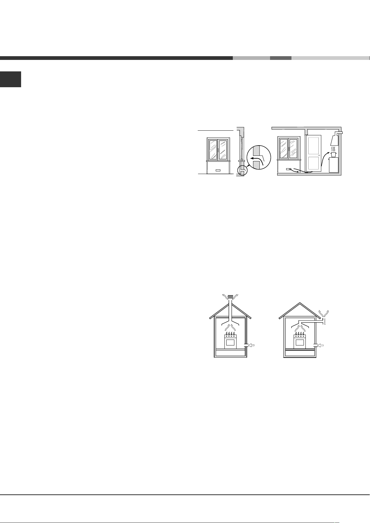
Room ventilation
The appliance may only be installed in permanentlyventilated rooms, according to current national
legislation. The room in which the appliance is
installed must be ventilated adequately so as to
provide as much air as is needed by the normal gas
combustion process (the flow of air must not be
3
lower than 2 m
/h per kW of installed power).
The air inlets, protected by grilles, should have a
duct with an inner cross section of at least 100 cm
2
and should be positioned so that they are not liable
to even partial obstruction (see figure A).
These inlets should be enlarged by 100% - with a
2
minimum of 200 cm
- whenever the surface of the
hob is not equipped with a flame failure safety
device. When the flow of air is provided in an
indirect manner from adjacent rooms (see figure B),
provided that these are not communal parts of a
building, areas with increased fire hazards or
bedrooms, the inlets should be fitted with a
ventilation duct leading outside as described above.
Adjacent room Room requiring
ventilation
A B
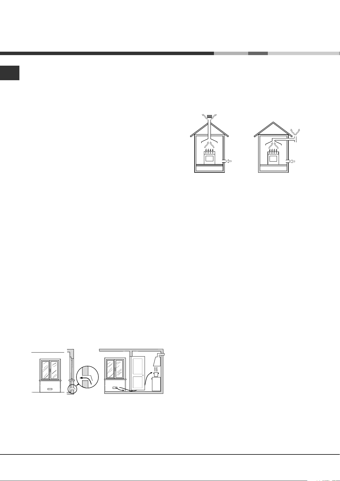
Disposing of combustion fumes
The disposal of combustion fumes should be
guaranteed using a hood connected to a safe and
efficient natural suction chimney, or using an electric
fan that begins to operate automatically every time
the appliance is switched on (see figure).
Fumes channelled
straight outside
Fumes channelled through
a chimney or a branched
flue system (reserved for
cooking appliances)
The liquefied petroleum gases are heavier than air
and collect by the floor, therefore all rooms
containing LPG cylinders must have openings
leading outside so that any leaked gas can escape
easily.
LPG cylinders, therefore, whether partially or
completely full, must not be installed or stored in
rooms or storage areas that are below ground level
(cellars, etc.). Only the cylinder being used should
be stored in the room; this should also be kept well
away from sources of heat (ovens, chimneys,
stoves) that may cause the temperature of the
cylinder to rise above 50°C.
Positioning and levelling
It is possible to install the appliance alongside
cupboards whose height does not exceed that of the
hob surface.
Make sure that the wall in contact with the back of
the appliance is made from a non-flammable, heatresistant material (T 90°C).
A
Ventilation opening
for comburent air
Increase in the gap
between the door and
the flooring
After prolonged use of the appliance, it is
advisable to open a window or increase the speed of
any fans used.
2
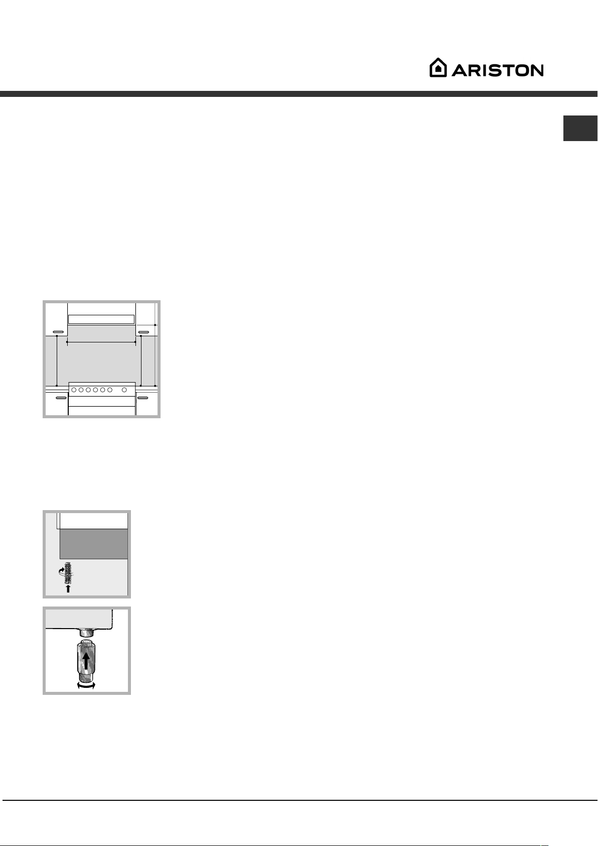
To install the appliance correctly:
Place it in the kitchen, dining room or the bed-sit
(not in the bathroom).
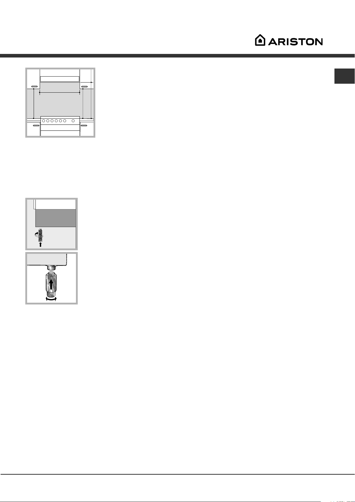
If the top of the hob is higher than the cupboards,
the appliance must be installed at least 600 mm
away from them.
If the cooker is installed underneath a wall
cabinet, there must be a minimum distance of 420
mm between this cabinet and the top of the hob.
This distance should be increased to 700 mm if the
wall cabinets are flammable (see figure).
Page 3
mm.
420
Min.
HOOD
Min. mm.
600
mm. with hood
420
650
Min. mm.
min.
mm. without hood
700
min.
The voltage is in the range between the values
indicated on the data plate.
The socket is compatible with the plug of the
appliance. If the socket is incompatible with the
plug, ask an authorised technician to replace it.
Do not use extension cords or multiple sockets.
Once the appliance has been installed, the power
supply cable and the electrical socket must be
easily accessible.
GB
Do not position blinds behind the cooker or less
than 200 mm away from its sides.
Any hoods must be installed according to the
instructions listed in the relevant operating manual.
Levelling
If it is necessary to level the
appliance, screw the
adjustable feet into the places
provided on each corner of the
base of the cooker (see figure).
The legs* fit into the slots on
the underside of the base of
the cooker.
Electrical connection
Install a standardised plug corresponding to the
load indicated on the appliance data plate (see
Technical data table).
The appliance must be directly connected to the mains
using an omnipolar circuit-breaker with a minimum
contact opening of 3 mm installed between the
appliance and the mains. The circuit-breaker must be
suitable for the charge indicated and must comply with
current national legislation (the earthing wire must not
be interrupted by the circuit-breaker). The supply cable
must be positioned so that it does not come into
contact with temperatures higher than 50°C at any point.
Before connecting the appliance to the power
supply, make sure that:
The appliance is earthed and the plug is compliant
with the law.
The socket can withstand the maximum power of
the appliance, which is indicated by the data plate.
* Only available in certain models
The cable must not be bent or compressed.
The cable must be checked regularly and replaced
by authorised technicians only.
The manufacturer declines any liability should
these safety measures not be observed.
Gas connection
Connection to the gas network or to the gas cylinder
may be carried out using a flexible rubber or steel
hose, in accordance with current national legislation
and after making sure that the appliance is suited to
the type of gas with which it will be supplied (see the
rating sticker on the cover: if this is not the case see
below). When using liquid gas from a cylinder, install a
pressure regulator which complies with current national
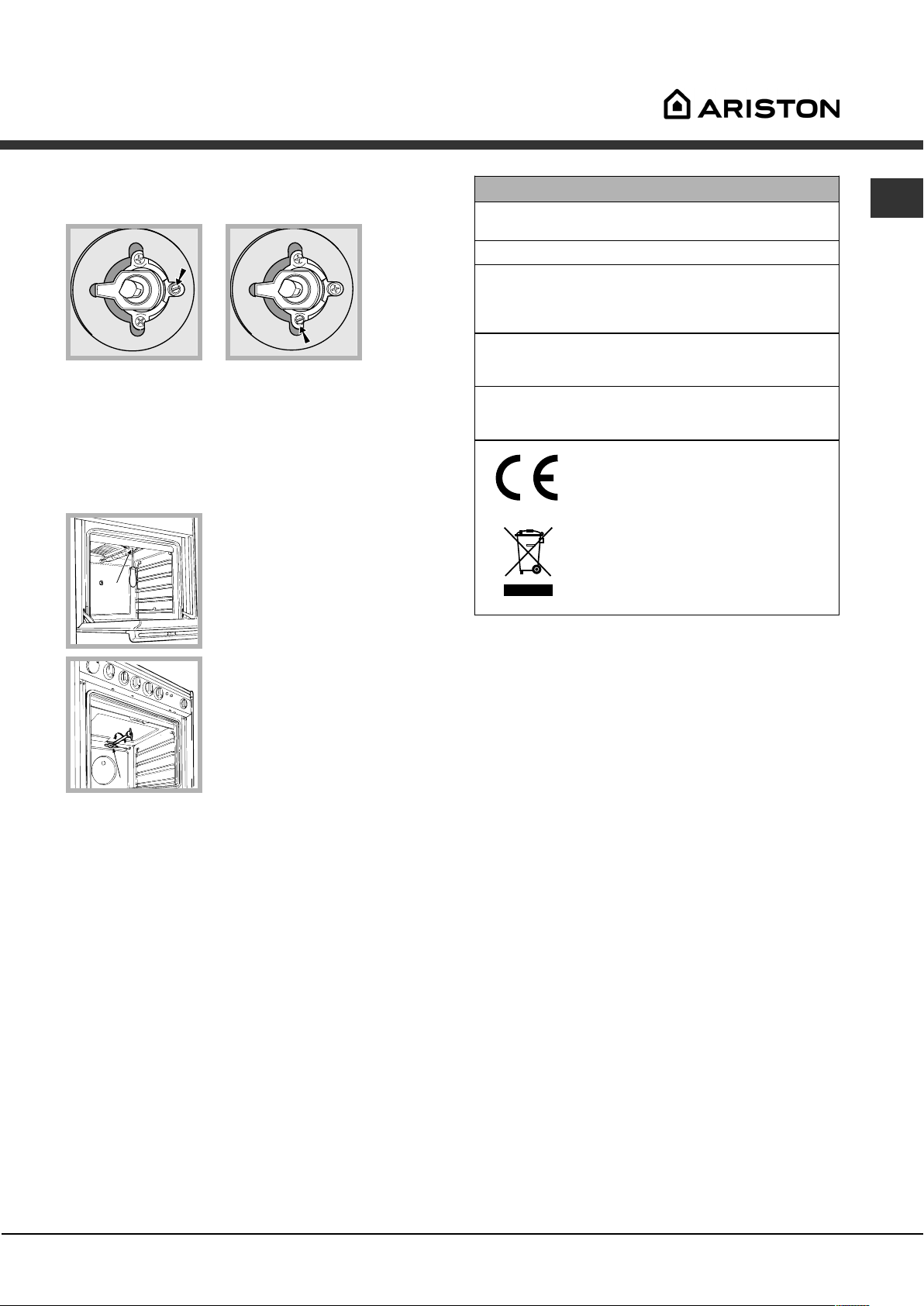
regulations. To make connection easier, the gas
supply may be turned sideways*: reverse the position
of the hose holder with that of the cap and replace the
gasket that is supplied with the appliance.
Check that the pressure of the gas supply is
consistent with the values indicated in the Table of
burner and nozzle specifications (see below). This
will ensure the safe operation and durability of your
appliance while maintaining efficient energy
consumption.
Gas connection using a flexible rubber hose
Make sure that the hose complies with current
national legislation. The internal diameter of the hose
must measure: 8 mm for liquid gas supply; 13 mm
for methane gas supply.
Once the connection has been performed, make
sure that the hose:
Does not come into contact with any parts that
reach temperatures of over 50°C.
Is not subject to any pulling or twisting forces and
that it is not kinked or bent.
Does not come into contact with blades, sharp
corners or moving parts and that it is not
compressed.
3
Page 4
GB
Is easy to inspect along its whole length so that
its condition may be checked.
Is shorter than 1500 mm.
Fits firmly into place at both ends, where it will be
fixed using clamps that comply with current
regulations.
If one or more of these conditions is not fulfilled or if
the cooker must be installed according to the conditions
listed for class 2 - subclass 1 appliances (installed
between two cupboards), the flexible steel hose must
be used instead (see below).
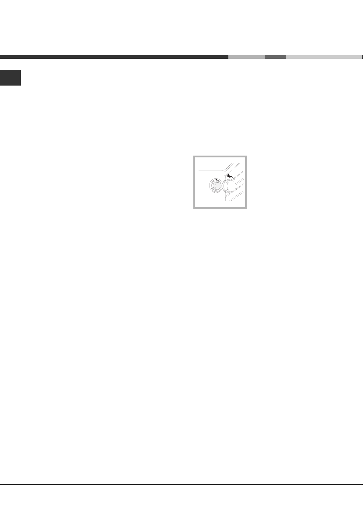
Adjusting the hob burners minimum setting:
1. Turn the tap to the minimum position.
2. Remove the knob and adjust the regulatory
screw, which is positioned inside or next to the tap
pin, until the flame is small but steady.
If the appliance is connected to a liquid gas
supply, the regulatory screw must be fastened as
tightly as possible.
3. While the burner is alight, quickly change the position
of the knob from minimum to maximum and vice versa
several times, checking that the flame is not
extinguished.
Connecting a flexible jointless stainless steel
pipe to a threaded attachment
Make sure that the hose and gaskets comply with
current national legislation.
To begin using the hose, remove the hose holder on
the appliance (the gas supply inlet on the appliance
is a cylindrical threaded 1/2 gas male attachment).
Perform the connection in such a way that the hose
length does not exceed a maximum of 2 metres,
making sure that the hose is not compressed and
does not come into contact with moving parts.
Checking the tightness of the connection
When the installation process is complete, check the
hose fittings for leaks using a soapy solution. Never
use a flame.
Adapting to different types of gas
It is possible to adapt the appliance to a type of gas
other than the default type (this is indicated on the
rating label on the cover).
Adapting the hob
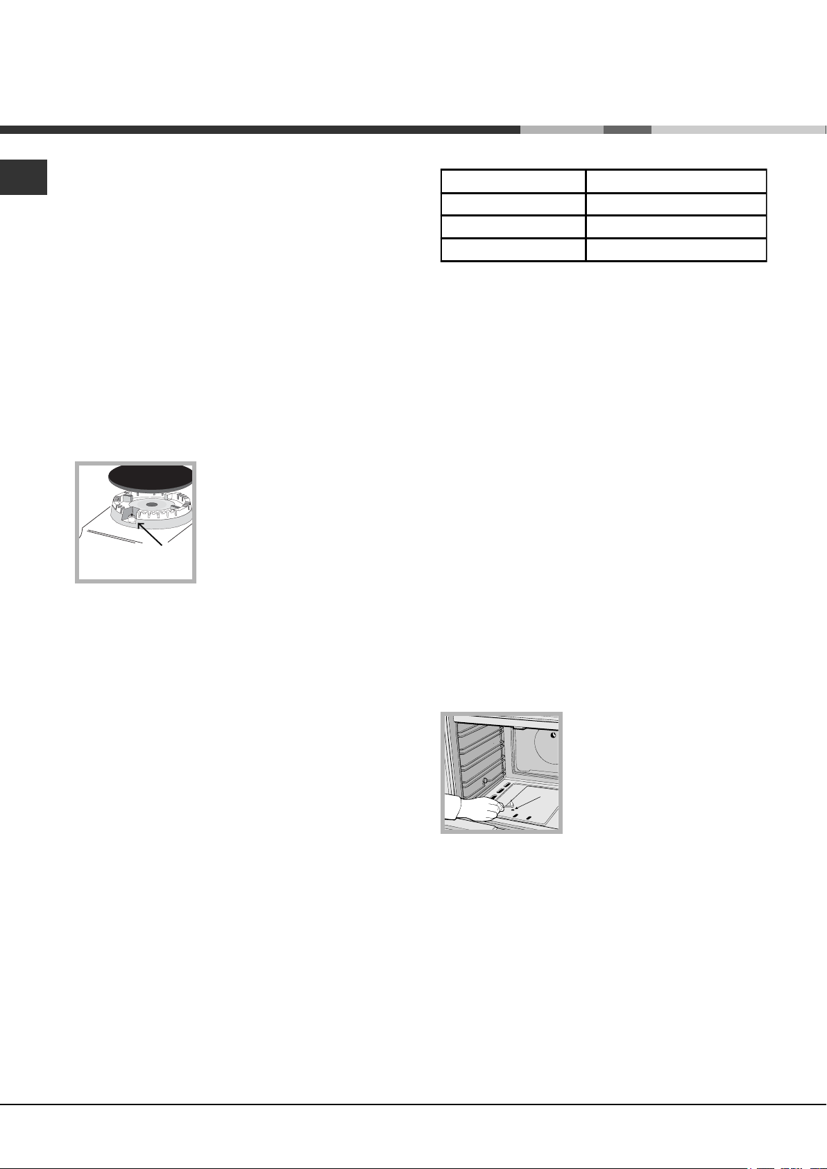
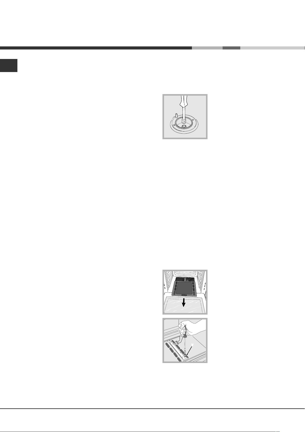
Replacing the nozzles for the hob burners:
1. Remove the hob grids and slide the burners off
their seats.
2. Unscrew the nozzles using
a 7 mm socket spanner (see
figure), and replace them with
nozzles suited to the new type
of gas (see Burner and nozzle
specifications table).
3. Replace all the components
by following the above
instructions in reverse.
The hob burners do not require primary air adjustment.
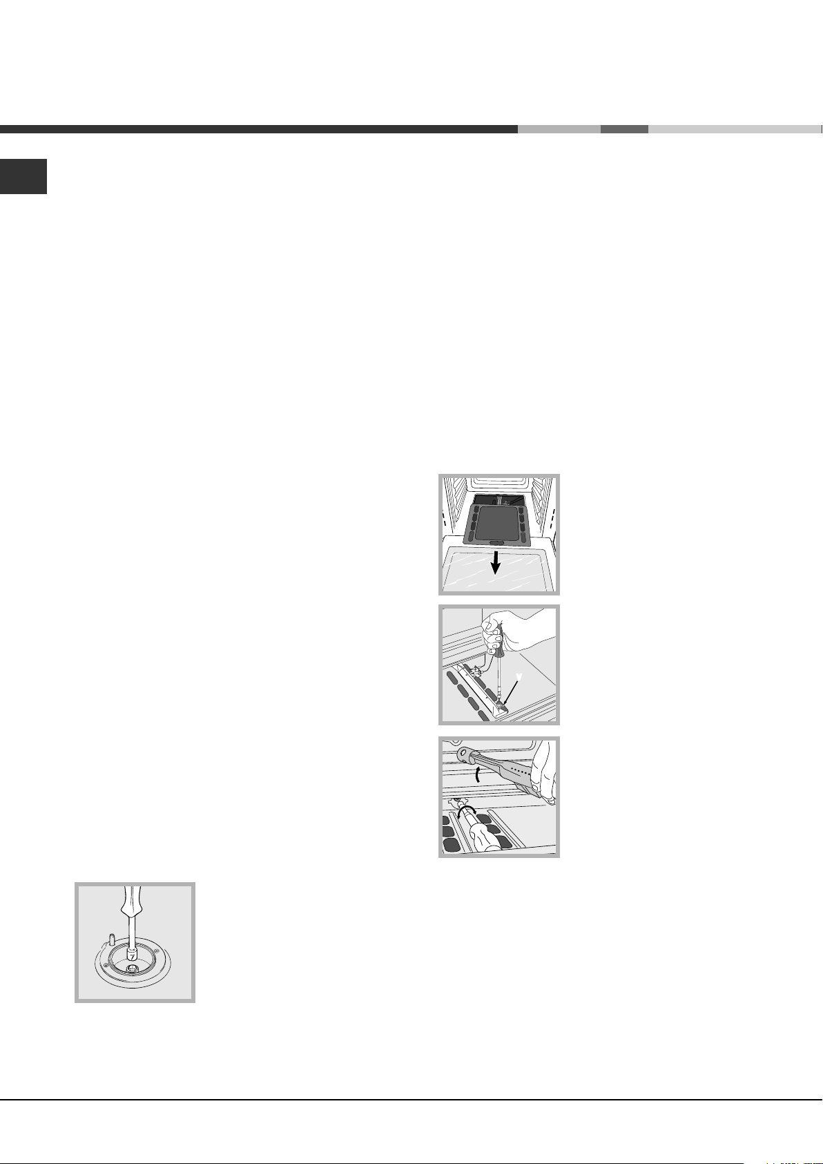
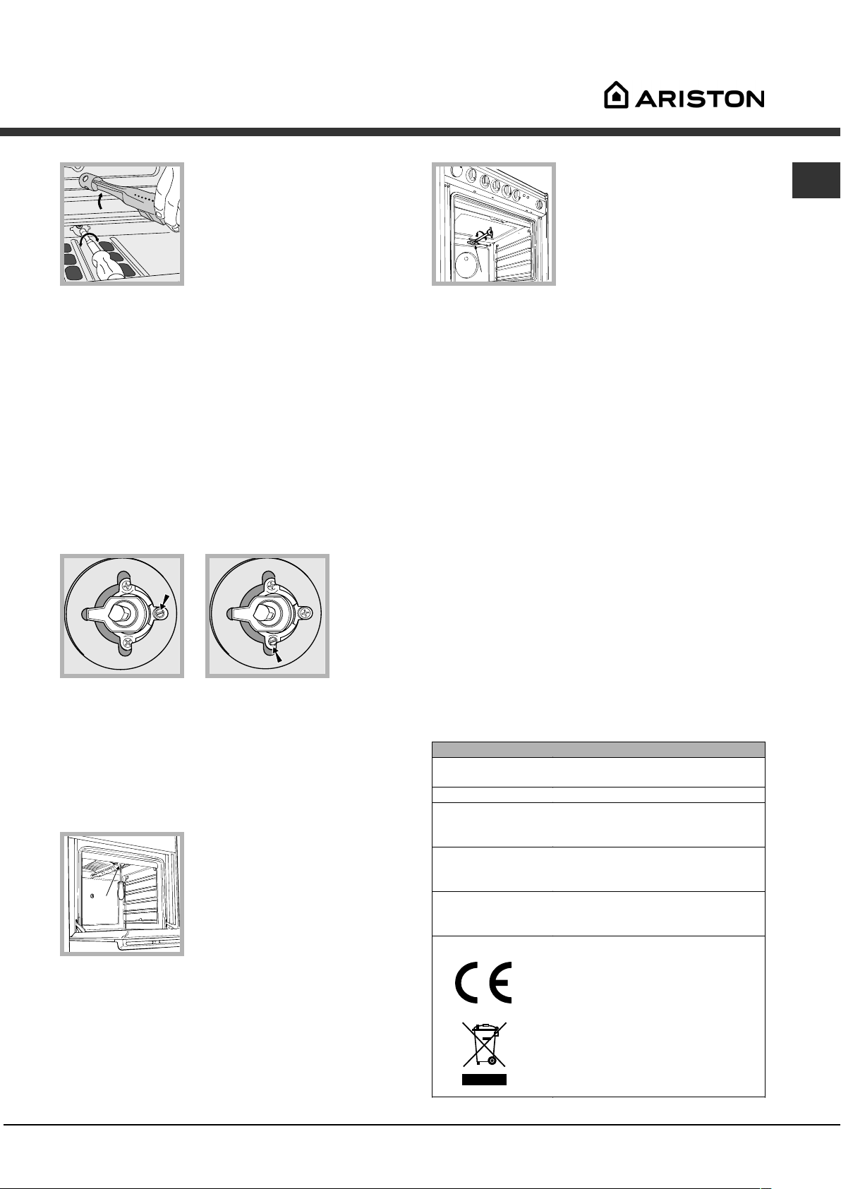
Adapting the oven
Replacing the oven burner nozzle:
1. Open the oven door fully
2. Pull out the sliding oven
bottom (see diagram).
3. Remove the oven burner
after unscrewing the screws V
(see figure).
V
4. Unscrew the nozzle using a
special nozzle socket spanner
(see figure) or with a 7 mm
socket spanner, and replace it
with a new nozzle that is
suited to the new type of gas
(see Burner and nozzle
specifications table).
Adjusting the gas oven burners minimum
setting:
1. Light the burner (see Start-up and Use).
2. Turn the knob to the minimum position (MIN) after
it has been in the maximum position (MAX) for
approximately 10 minutes.
3. Remove the knob.
4. Tighten or loosen the adjustment screws on the
outside of the thermostat pin (see figure) until the
flame is small but steady.
4
Page 5
In the case of natural gas, the adjustment screw must
I
be unscrewed by turning it anti-clockwise.
TECHNICAL DATA
Oven Dimensions
HxWxD
Volume
Useful
measurements
relating to the
oven compartment
GB
31x43,5x43,5 cm
58 l
width 46 cm
depth 42 cm
height 8,5 cm
5. Turn the knob from the MAX position to the MIN
position quickly or open and shut the oven door,
making sure that the burner is not extinguished.
Adapting the grill
Replacing the grill burner nozzle:
1. Remove the oven burner
after loosening screw V (see
figure).
V
2. Unscrew the grill burner
nozzle using a special nozzle
socket spanner (see figure) or
preferably with a 7 mm socket
spanner, and replace it with a
new nozzle that is suited to the
new type of gas (see Burner
and nozzle specifications table).
Voltage and
frequency
Burners
see data plate
may be adapted for use with any
type of gas shown on the data
plate.
EC Directives 73/23/EEC dated
19/02/73 (Low Voltage) and
subsequent amendments 89/336/EEC dated 03/05/89
(Electromagnetic Compatibility)
and subsequent amendments -
90/369/EEC dated 29/06/90 (Gas)
and subsequent amendments -
90/68/EEC dated 22/07/93 and
subsequent amendments. 2002/96/EEC.
Be careful of the spark plug wires and the
thermocouple tubes.
The oven and grill burners do not require primary
air adjustment.
After adjusting the appliance so it may be used
with a different type of gas, replace the old rating
label with a new one that corresponds to the new
type of gas (these labels are available from
Authorised Technical Assistance Centres).
Should the gas pressure used be different (or vary
slightly) from the recommended pressure, a suitable
pressure regulator must be fitted to the inlet hose in
accordance with current national regulations relating
to regulators for channelled gas.
5
Page 6
GB
g
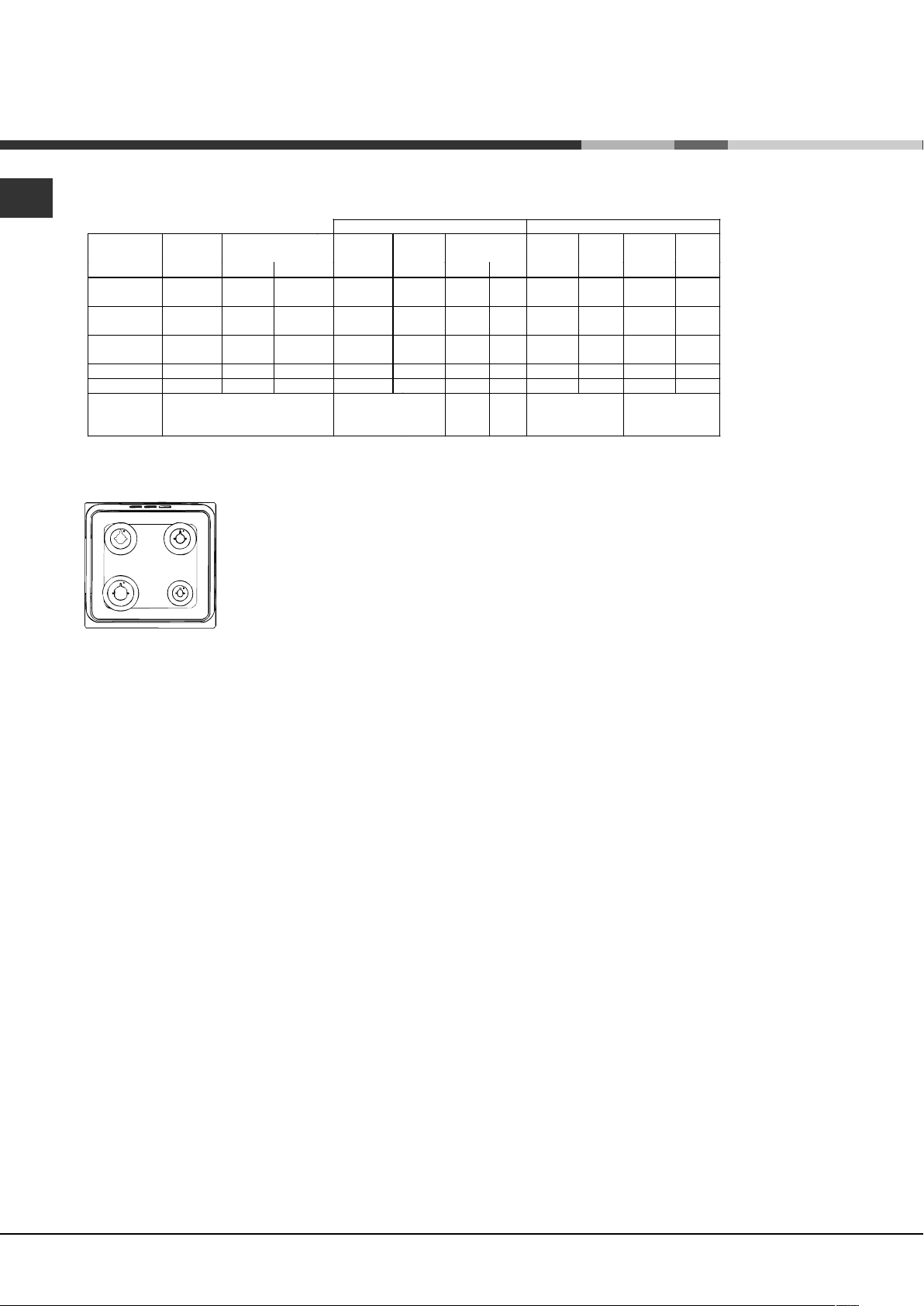
Table of burner and nozzle specifications
Table 1 Liquid Gas Natural Gas
Burner
Diameter
(mm)
Thermal Power
kW (p.c.s.*)
By Pass
1/100
Nozzle
1/100
Flow*
g/h
Nozzle
1/100
Flow*
l/h
Nozzle
1/100
Nominal Reduced (mm) (mm) *** ** (mm) (mm)
Fast
(Large)(R)
Semi Fast
(Medium)(S)
Auxiliary
(Small)(A)
100 3.00 0.7 41 86 218 214 116 286 143 286
75 1.90 0.4 30 70 138 136 106 181 118 181
55 1.00 0.4 30 50 73 71 79 95 80 95
Oven - 2.60 1.0 52 78 189 186 119 189 132 238
Grill - 2.50 - - 80 182 179 122 238 139 227
Supply
Pressures
Nominal (mbar)
Minimum (mbar)
Maximum (mbar)
28-30
20
35
37
25
45
20
17
25
13
6,5
18
* At 15°C 1013 mbar-dry gas *** Butane P.C.S. = 49,47 MJ/Kg
** Propane P.C.S. = 50,37 MJ/K
S
S
R
A
Natural P.C.S. = 37,78 MJ/m³
CG64SG1 EX
Flow*
l/h
6
Page 7
Description of the
appliance
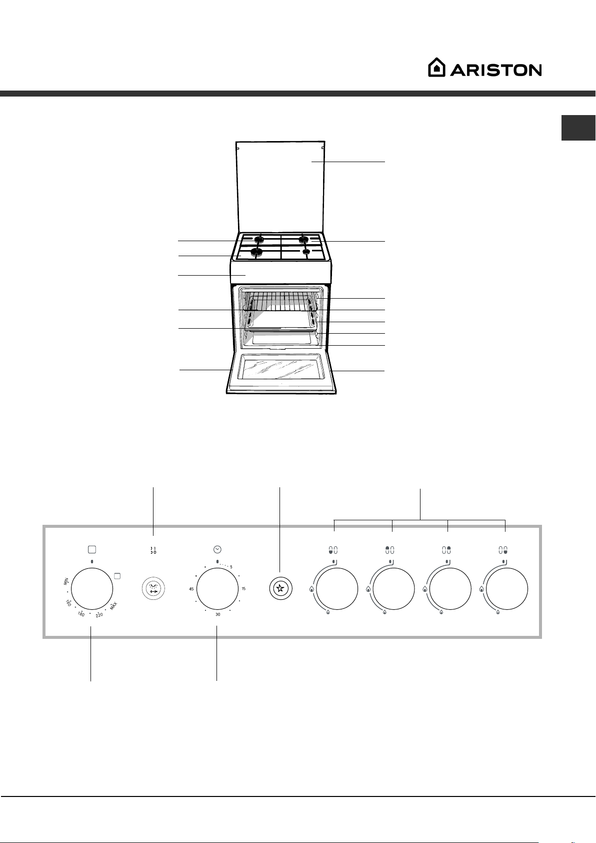
Overall view
Gas burner
Hob grid
Control panel
GRILL rack
DRIPPING PAN
Adjustable foot
Glass cover
Containment
surface for spills
GUIDE RAILS
for the sliding racks
position 5
position 4
position 3
position 2
position 1
Adjustable foot
*
GB
Control panel
OVEN LIGHT and
ROTISSERIE button
OVEN
control knob
GAS BURNER
ignition button*
TIMER
knob*
Hob BURNER
control knobs
Only available in certain models.
*
7
Page 8
Start-up and use
)
GB
Using the hob
Lighting the burners
For each BURNER knob there is a complete ring
showing the strength of the flame for the relevant
burner.
To light one of the burners on the hob:
1. Bring a flame or gas lighter close to the burner.
2. Press the BURNER knob and turn it in an
anticlockwise direction so that it is pointing to the
maximum flame setting -.
3. Adjust the intensity of the flame to the desired
level by turning the BURNER knob in an
anticlockwise direction. This may be the minimum
setting +, the maximum setting - or any position in
between the two.
If the appliance is fitted with
an electronic lighting device*
(see figure), press the ignition
button, marked with the
symbol
BURNER knob down and turn
it in an anticlockwise direction,
towards the maximum flame setting, until the burner
is lit.The burner may be extinguished when the knob
is released. If this occurs, repeat the operation,
holding the knob down for a longer period of time.
, then hold the
Burner ø Cookware diameter (cm
Fast (R) 24 - 26
Semi Fast (S) 16 - 20
Auxiliary (A) 10 - 14
To identify the type of burner, please refer to the
diagrams contained in the Burner and nozzle
specifications.
On the models supplied with a reducer shelf,
remember that this should be used only for the
auxiliary burner when you use casserole dishes with
a diameter under 12 cm.
Using the oven
The first time you use your appliance, heat the
empty oven with its door closed at its maximum
temperature for at least half an hour. Ensure that the
room is well ventilated before switching the oven off
and opening the oven door. The appliance may emit
a slightly unpleasant odour caused by protective
substances used during the manufacturing process
burning away.
Never put objects directly on the bottom of the
oven; this will avoid the enamel coating being
damaged. Only use position 1 in the oven when
cooking with the rotisserie spit.
If the flame is accidentally extinguished, switch off
the burner and wait for at least 1 minute before
attempting to relight it.
If the appliance is equipped with a flame failure
safety device*, press and hold the BURNER knob
for approximately 2-3 seconds to keep the flame
alight and to activate the device.
To switch the burner off, turn the knob until it
reaches the stop position
Practical advice on using the burners
For the burners to work in the most efficient way
possible and to save on the amount of gas
consumed, it is recommended that only pans that
have a lid and a flat base are used. They should also
be suited to the size of the burner.
Only available in certain models.
*
.
Lighting the oven
To light the oven burner, bring
a flame or gas lighter close to
opening F (see figure) and
press the OVEN control knob
while turning it in an
F
anticlockwise direction until it
reaches the MAX position.
If the appliance is fitted with an electronic lighting
device* (see figure), press the ignition button,
marked with the symbol
control knob and turn it in an anticlockwise direction,
towards the MAX position, until the burner is lit. If,
after 15 seconds, the burner is still not alight,
release the knob, open the oven door and wait for at
least 1 minute before trying to light it again. If there
is no electricity the burner may be lit using a flame
or a lighter, as described above.
The oven is fitted with a safety device and it is
therefore necessary to hold the OVEN control knob
, then hold the OVEN
8
Page 9
down for approximately 6 seconds.
If the flame is accidentally extinguished, switch off
the burner and wait for at least 1 minute before
attempting to relight the oven.
Adjusting the temperature
To set the desired cooking temperature, turn the
OVEN control knob in an anticlockwise direction.
Temperatures are displayed on the control panel and
may vary between MIN (150°C) and MAX (250°C).
Once the set temperature has been reached, the
oven will keep it constant by using its thermostat.
Grill
To light the grill, bring a flame or gas lighter close to
the burner and press the OVEN control knob while
turning it in a clockwise direction until it reaches the
@ position. The grill enables the surface of food to
be browned evenly and is particularly suitable for
roast dishes, schnitzel and sausages. Place the
rack in position 4 or 5 and the dripping pan in
position 1 to collect fat and prevent the formation of
smoke.
The grill is fitted with a safety device and it is
therefore necessary to hold the OVEN control knob
down for approximately 6 seconds.
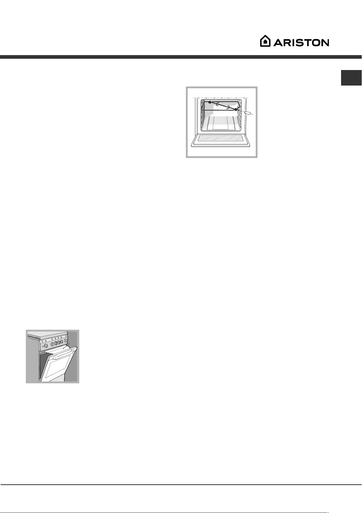
Turnspit
GB
To operate the
rotisserie (see diagram)
proceed as follows:
1. Place the dripping
pan in position 1.
2. Place the rotisserie
support in position 4
and insert the spit in the
hole provided on the
back panel of the oven.
3. Acitvate the function by pressing the TURNSPIT
button.
Oven light
The light may be switched on at any moment by
pressing the OVEN LIGHT button.
Timer*
To activate the Timer proceed as follows:
1. Turn the TIMER knob in a clockwise direction "
for almost one complete revolution to set the buzzer.
2. Turn the TIMER knob in an anticlockwise direction
# to set the desired length of time.
If the flame is accidentally extinguished, switch off
the burner and wait for at least 1 minute before
attempting to relight the grill.
When using the grill, leave
the oven door ajar, positioning
D
the deflector D between the
door and the control panel
(see figure) in order to prevent
the knobs from overheating.
Only available in certain models.
*
9
Page 10
GB
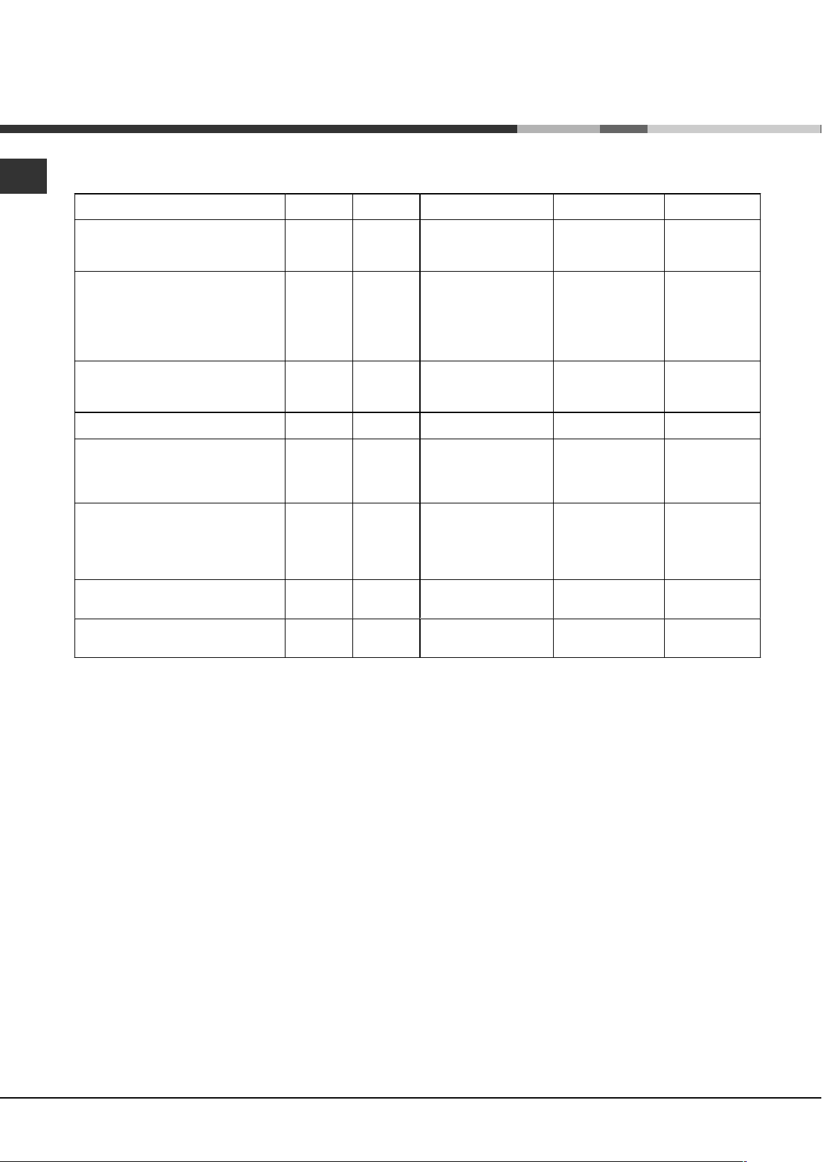
Oven cooking advice table
Foods Weight (in
Pasta
Lasagne
Cannelloni
Gratin dishes
Meat
Veal
Chicken
Duck
Rabbit
Pork
Lamb
Fish
Mackerel
Dentex
Trout baked in foil
Pizza
Neapolitan-style 1 3 15 220 15-20
Pies
Biscuits
Tart
Savoury pies
Leavened cakes
Grilled foods
Veal steak
Cutlets
Hamburgers
Mackerel
Toast
Grillling using the rotisserie
Spit-roast veal
Spit-roast chicken
Grillling using the multi-spit rotisserie*
Meat kebabs
Vegetable kebabs
kg)
2.5
2.5
2.5
1.7
1.5
1.8
2
2.1
1.8
1.1
1.5
1
0.5
1.1
1
1
1
1.5
1
1
4 pcs
1
2
1
0.8
Rack
position
3
3
3
3
3
3
3
3
3
3
3
3
3
3
3
3
4
4
3
4
4
-
-
-
-
Preheating time (min) Recommended
10
10
10
10
10
10
10
10
10
10
10
10
15
15
15
15
5
5
5
5
5
5
5
5
5
Temperature (°C)
210
200
200
200
220
200
200
200
200
180-200
180-200
180-200
180
180
180
180
Cooking time
(minutes)
60-75
40-50
40-50
85-90
90-100
100-110
70-80
70-80
90-95
35-40
40-50
40-45
30-35
30-35
45-50
35-40
15-20
15-20
70-80
70-80
40-45
25-30
20
7
5
10
Page 11
Precautions and tips
This appliance has been designed and manufactured
in compliance with international safety standards.
The following warnings are provided for safety
reasons and must be read carefully.
General safety
The appliance was designed for domestic use
inside the home and is not intended for
commercial or industrial use.
The appliance must not be installed outdoors, even
in covered areas. It is extremely dangerous to
leave the appliance exposed to rain and storms.
Do not touch the appliance with bare feet or with
wet or damp hands and feet.
The appliance must be used by adults only for the
preparation of food, in accordance with the
instructions provided in this booklet (the
instructions apply to all countries listed at the
beginning of the booklet).
The instruction booklet accompanies a class 1
(insulated) or class 2 - subclass 1 (recessed
between 2 cupboards) appliance.
When the appliance is in use, the heating
elements and some parts of the oven door
become extremely hot. Make sure you don't
touch them and keep children well away.
Make sure that the power supply cables of other
electrical appliances do not come into contact
with the hot parts of the oven.
The openings used for the ventilation and
dispersion of heat must never be covered.
Do not close the glass hob cover (selected
models only) when the burners are alight or when
they are still hot.
Always use oven gloves when placing cookware
in the oven or when removing it.
Do not use flammable liquids (alcohol, petrol,
etc...) near the appliance while it is in use.
Do not place flammable material in the lower
storage compartment or in the oven itself. If the
appliance is switched on accidentally, it could
catch fire.
The internal surfaces of the compartment (where
present) may become hot.
Always make sure the knobs are in the
and that the gas tap is closed when the appliance
is not in use.
When unplugging the appliance, always pull the plug
from the mains socket; do not pull on the cable.
Never perform any cleaning or maintenance work
without having disconnected the appliance from
the electricity mains.
If the appliance breaks down, under no
circumstances should you attempt to repair the
appliance yourself. Repairs carried out by
inexperienced persons may cause injury or further
malfunctioning of the appliance. Contact Assistance.
Do not rest heavy objects on the open oven door.
position
Disposal
When disposing of packaging material: observe local
legislation so that the packaging may be reused.
The European Directive 2002/96/EC on Waste
Electrical and Electronic Equipment (WEEE),
requires that old household electrical appliances
must not be disposed of in the normal unsorted
municipal waste stream. Old appliances must be
collected separately in order to optimise the
recovery and recycling of the materials they contain
and reduce the impact on human health and the
environment. The crossed out wheeled bin
symbol on the product reminds you of your
obligation, that when you dispose of the appliance
it must be separately collected.
Consumers should contact their local authority or
retailer for information concerning the correct
disposal of their old appliance.
Respecting and conserving the
environment
You can help to reduce the peak load of the
electricity supply network companies by using the
oven in the hours between late afternoon and the
early hours of the morning.
Always keep the oven door closed when using the
GRILL mode This will achieve better results while
saving energy (approximately 10%).
Check the door seals regularly and wipe them clean
to ensure they are free of debris so that they adhere
properly to the door, thus avoiding heat dispersion.
GB
11
Page 12
Care and maintenance
GB
Switching the appliance off
Disconnect your appliance from the electricity
supply before carrying out any work on it.
Cleaning the appliance
Never use steam cleaners or pressure cleaners on
the appliance.
The stainless steel or enamel-coated external
parts and the rubber seals may be cleaned using
a sponge that has been soaked in lukewarm water
and neutral soap. Use specialised products for
the removal of stubborn stains. After cleaning,
rinse well and dry thoroughly. Do not use abrasive
powders or corrosive substances.
The hob grids, burner caps, flame spreader rings
and burners may be removed to make cleaning
easier; wash them in hot water and non-abrasive
detergent, making sure all burnt-on residue is
removed before drying them thoroughly.
Clean the terminal part of the flame failure safety
devices* frequently.
The inside of the oven should ideally be cleaned
after each use, while it is still lukewarm. Use hot
water and detergent, then rinse well and dry with
a soft cloth. Do not use abrasive products.
Inspecting the oven seals
Check the door seals around the oven regularly. If
the seals are damaged, please contact your nearest
Authorised After-sales Service Centre. We
recommend that the oven is not used until the seals
have been replaced.
Replacing the oven light bulb
1. After disconnecting the
oven from the electricity mains,
remove the glass lid covering
the lamp socket (see figure).
2. Remove the light bulb and
replace it with a similar one:
voltage 230 V, wattage 25 W,
cap E 14.
3. Replace the lid and reconnect the oven to the
electricity supply.
Gas tap maintenance
Over time, the taps may become jammed or difficult
to turn. If this happens, the tap must be replaced.
This procedure must be performed by a
qualified technician authorised by the
manufacturer.
Clean the glass part of the oven door using a
sponge and a non-abrasive cleaning product,
then dry thoroughly with a soft cloth. Do not use
rough abrasive material or sharp metal scrapers
as these could scratch the surface and cause the
glass to crack.
The accessories can be washed like everyday
crockery, and are even dishwasher safe.
Do not close the cover when the burners are alight
or when they are still hot.
Assistance
Never use the services of an unauthorised
technician.
Please have the following information to hand:
The type of problem encountered.
The appliance model (Mod.).
The serial number (S/N).
The latter two pieces of information can be found on
the data plate located on the appliance.
Only available in certain models.
*
12
Page 13
Mode demploi
CUISINIERE
GB
English, 1
GB
English, 37
CG64SG1 EX
FR
Français, 13
AR
ES
Espanol, 25
Sommaire
FR
Installation, 14-18
Positionnement et nivellement
Raccordement électrique
Raccordement gaz
Adaptation aux différents types de gaz
Caractéristiques techniques
Tableau Caractéristiques des brûleurs et des
injecteurs
Description de lappareil, 19
Vue densemble
Tableau de bord
Mise en marche et utilisation, 20-22
Utilisation du plan de cuisson
Utilisation du four
Tableau de cuisson
Précautions et conseils, 23
Sécurité générale
Mise au rebut
Economies et respect de lenvironnement
Nettoyage et entretien, 24
Mise hors tension
Nettoyage de lappareil
Entretien robinets gaz
Remplacement de lampoule déclairage du four
Assistance
Page 14
A
Installation
FR
Conservez ce mode demploi pour pouvoir le
consulter à tout moment. En cas de vente, de cession
ou de déménagement, veillez à ce quil suive
lappareil.
Lisez attentivement les instructions : elles
contiennent des conseils importants sur linstallation,
lutilisation et la sécurité de votre appareil.
Linstallation de lappareil doit être effectuée par un
professionnel du secteur conformément aux
instructions du fabricant.
Nimporte quelle opération de réglage, dentretien,
etc., doit être effectuée après avoir débranché la prise
de la cuisinière.
Conditions réglementaires dinstallation
Le raccordement gaz devra être fait par un
professionnel qualifié qui assurera la bonne
alimentation en gaz et le meilleur réglage de la
combustion des brûleurs. Ces opérations
dinstallation, quoique simples, sont délicates et
primordiales pour que votre cuisinière vous rende le
meilleur service. Linstallation doit être effectuée
conformément aux textes réglementaires et règles de
lart en vigueur, notamment:
Arrêté du 2 août 1977. Règles techniques et de
sécurité applicables aux installations de gaz
combustibles et dhydro-carbures liquéfiés situées
à lintérieur des bâtiments dhabitation et de leur
dépendances.
Norme DTU P45-204. Installations de gaz
(anciennement DTU n° 61-1-installations de gaz Avril 1982 + additif n°1 Juillet 1984).
Règlement sanitaire départemental.
pièces voisines (voir figure B) à condition quil ne
sagisse pas de parties communes du bâtiment, de
chambres à coucher ou de locaux à risque dincendie
équipées dun conduit daération avec lextérieur
comme décrit plus haut.
Local adjacent Local à ventiler
A B
Ouverture de ventilation
pour lair comburant
Après une utilisation prolongée de lappareil, il est
conseillé douvrir une fenêtre ou daugmenter la
vitesse de ventilateurs éventuels.
Evacuation des fumées de combustion
La pièce doit prévoir un système dévacuation vers
lextérieur des fumées de combustion réalisé au
moyen dune hotte reliée à une cheminée à tirage
naturel ou par ventilateur électrique qui entre
automatiquement en fonction dès quon allume
lappareil (voir figures).
Agrandissement de la
fissure entre la porte et
le sol
Aération des locaux
Lappareil doit être installé dans des locaux qui sont
aérés en permanence, selon les prescriptions des
Normes en vigueur dans le pays dinstallation. Il est
indispensable que la pièce où lappareil est installé
dispose dune quantité dair égale à la quantité dair
comburant nécessaire à une bonne combustion du
gaz (le flux dair doit être dau moins 3 m
puissance installée).
Les prises dair, protégées par des grilles, doivent
disposer dun conduit dau moins 2 cm2 de section
utile et dans une position qui leur évite tout risque
dêtre bouchées accidentellement, même
partiellement (voir figure A).
Ces ouvertures doivent être agrandies de 100%
(surface minimale 2 cm2) en cas dappareils
dépourvus du dispositif de sécurité de flamme et
quand lafflux de lair provient de manière indirecte de
"
3
/h par kW de
Evacuation
directement à
lextérieur
Les gaz de pétrole liquéfiés, plus lourds que lair, se
déposent et stagnent dans le bas. Les locaux qui
contiennent des bouteilles de G.P.L doivent donc
prévoir des ouvertures vers lextérieur afin de permettre
lévacuation du gaz par le bas en cas de fuites
accidentelles. Ne pas installer ou entreposer de
bouteilles de GPL, vides ou partiellement pleines, dans
des locaux qui se trouvent en sous-sol (caves etc.). Ne
gardez dans la pièce que la bouteille que vous êtes en
train dutiliser, loin de sources de chaleur (fours, feux
de bois, poêles etc.) qui pourraient amener sa
température à plus de 50°C.
Evacuation par cheminée ou
conduit de fumée ramifié (réservé
aux appareils de cuisson)
Page 15
Positionnement et nivellement
Lappareil peut être installé à côté de meubles dont
la hauteur ne dépasse pas celle du plan de cuisson.
Assurez-vous que le mur en contact avec la paroi
arrière de lappareil est réalisée en matériel ignifuge
résistant à la chaleur (T 90°C).
Pour une installation correcte :
installez cet appareil dans une cuisine, une salle à
manger ou un studio (jamais dans une salle de
bains);
si le plan de cuisson de la cuisinière dépasse le
plan de travail des meubles, ces derniers doivent
être placés à au moins 200 mm de lappareil;
si la cuisinière est
HOOD
Min. mm.
600
mm.
420
Min.
420
Min. mm.
ne placez pas de rideaux derrière la cuisinière ou
sur ses côtés à moins de 200 mm de distance;
pour linstallation de hottes, conformez-vous aux
instructions de leur notice demploi.
installée sous un
élément suspendu, il
faut que ce dernier soit
placé à au moins 420mm
de distance du plan. Il
mm. with hood
mm. without hood
650
700
faut prévoir une distance
min.
min.
de 700mm si les
éléments suspendus sont
inflammables (voir
figure);
intercaler entre lappareil et le réseau un interrupteur à
coupure omnipolaire ayant au moins 3 mm
décartement entre les contacts, dimensionné à la
charge et conforme aux normes en vigueur (le fil de
terre ne doit pas être interrompu par linterrupteur). Le
câble dalimentation ne doit atteindre, en aucun point,
des températures dépassant de 50°C la température
ambiante.
Avant de procéder au branchement, assurez-vous que :
la prise est bien munie dune terre conforme à la loi;
la prise est bien apte à supporter la puissance
maximale de lappareil, indiquée sur la plaquette
signalétique;
la tension dalimentation est bien comprise entre les
valeurs indiquées sur la plaquette signalétique;
la prise est bien compatible avec la fiche de
lappareil. Si ce nest pas le cas, remplacez la prise
ou la fiche, nutilisez ni rallonges ni prises multiples.
Après installation de lappareil, le câble électrique et
la prise de courant doivent être facilement
accessibles
Le câble ne doit être ni plié ni excessivement écrasé.
Le câble doit être contrôlé périodiquement et ne
peut être remplacé que par un technicien agréé.
Nous déclinons toute responsabilité en cas de
non respect des normes énumérées ci-dessus.
Raccordement gaz
FR
Nivellement
Pour mettre lappareil bien à
plat, vissez les pieds de
réglage fournis aux
emplacements prévus aux
coins à la base de la cuisinière
(voir figure).
Montage des pieds* par
encastrement sous la base.
Raccordement électrique
Montez sur le câble une prise normalisée pour la
charge indiquée sur létiquette des caractéristiques
(voir tableau des caractéristiques techniques).
En cas de raccordement direct au réseau, il faut
Pour raccorder lappareil au réseau de distribution du
gaz ou à la bouteille de gaz utilisez un tuyau flexible
en caoutchouc ou en acier, conformément à la
réglementation en vigueur. Assurez-vous auparavant
que lappareil est bien réglé pour le type de gaz
dalimentation utilisé (voir étiquette sur le couvercle :
autrement voir ci-dessous). Si lalimentation seffectue
avec du gaz liquide en bouteille, utilisez des
régulateurs de pression conformes à la
réglementation en vigueur dans le pays. Pour
simplifier le raccordement, lalimentation du gaz est
orientable latéralement* : inversez labout annelé avec
le bouchon de fermeture et remplacez le joint
détanchéité (fourni avec lappareil).
Pour un fonctionnement en toute sécurité, pour un
meilleur emploi de lénergie et une plus longue durée
de vie de lappareil, vérifiez que la pression
dalimentation respecte bien les valeurs indiquées
dans le tableau Caractéristiques des brûleurs et des
injecteurs (voir ci-dessous).
*Nexiste que sur certains modèles
#
Page 16
FR
Raccordement gaz par tuyau flexible en caoutchouc
Assurez-vous que le tuyau est bien conforme aux
normes applicables dans le pays dinstallation. Le
tuyau doit avoir un diamètre intérieur de : 8 mm en cas
dalimentation au gaz liquide; 15 mm en cas
dalimentation au gaz naturel.
Après avoir effectué le raccordement, assurez-vous
que le tuyau :
ne touche en aucun point à des parties pouvant
atteindre plus de 50°C;
ne soit pas soumis à traction ou torsion et ne
présente pas de pliures ou étranglements;
ne risque pas dentrer en contact avec des corps
tranchants, des arêtes vives, des parties mobiles et
ne soit pas écrasé;
puisse être facilement contrôlable sur toute sa
longueur pour vérifier son état de conservation;
ait moins de 1500mm de long;
soit bien fixé à ses deux extrémités à laide de
bagues de serrage conformes à la réglementation
en vigueur dans le pays.
Si une ou plusieurs de ces conditions ne peuvent
être remplies ou que la cuisinière est installée dans
des conditions de classe 2 sous-classe 1 (appareil
encastré entre deux meubles), il faut utiliser un tuyau
flexible en acier (voir ci-dessous).
Raccordement gaz par tuyau flexible en acier inox,
à paroi continue avec raccords filetés
Assurez-vous que le tuyau et les joints sont bien
conformes aux normes applicables dans le pays
dinstallation.
Pour installer le tuyau, enlevez labout annelé équipant
lappareil (le raccord dentrée du gaz à lappareil est
fileté 1/2 gaz mâle cylindrique).
Adaptation du plan de cuisson
Remplacement des injecteurs des brûleurs du plan de
cuisson:
1.enlevez les grilles du plan de cuisson et sortez les
brûleurs de leur logement;
2. dévissez les injecteurs à
laide dune clé à tube de 7mm
(voir figure), et remplacez-les
par les injecteurs adaptés au
nouveau type de gaz (voir
tableau Caractéristiques des
brûleurs et des injecteurs) ;
3.remontez les différentes parties en effectuant les
opérations dans le sens inverse.
Réglage des minima des brûleurs du plan de
cuisson :
1.placez le robinet sur la position minimum;
2.enlevez le bouton et tournez la vis de réglage
positionnée à lintérieur ou sur le côté de la tige du
robinet jusquà obtenir une petite flamme régulière;
En cas de gaz naturel, il faut dévisser la vis de
réglage en tournant dans le sens inverse des aiguilles
dune montre;
3.vérifiez si, en tournant rapidement le robinet du
maximum au minimum, le brûleur ne séteint pas.
Les brûleurs du plan de cuisson ne nécessitent pas
de réglage de lair primaire.
Adaptation du four
Remplacement du brûleur du four:
1. ouvrez complètement la porte du four;
2. enlever la protection
coulissante
(voir figure);
Procédez au raccordement de manière à ce que la
longueur du tuyau ne dépasse pas 2 mètres
dextension maximale. Veillez à ce que le tuyau ne
soit pas écrasé et ne touche en aucun point à des
parties mobiles.
Vérification de létanchéité
Une fois linstallation terminée, vérifiez létanchéité de
tous les raccords en utilisant une solution
savonneuse, nutilisez jamais de flamme.
Adaptation aux différents types de gaz
Lappareil peut être adapté à un type de gaz autre
que celui pour le quel il a été conçu (indiqué sur
létiquette de réglage sur le couvercle).
$
3. déposer le brûleur du four
après avoir enlevé la vis V (voir
figure);
V
Page 17
4. dévisser linjecteur du brûleur
à laide de la clé à tube spéciale
pour injecteurs (voir figure) ou
dune clé à tube de 7 mm et le
remplacer par linjecteur adapté
au nouveau type de gaz (voir
tableau Caractéristiques des
brûleurs et des injecteurs).
Réglage du minimum du brûleur du four à gaz :
1. allumer le brûleur (voir Mise en marche et
Utilisation);
2. amener la manette sur la position minimum (MIN)
après lavoir laissée pendant environ 10 minutes sur la
position maximum (MAX);
3. enlever le bouton;
4. agir sur la vis de réglage positionnée à lextérieur
de la tige du thermostat (voir figure) jusquà obtenir
une petite flamme régulière.
En cas de gaz naturel, il faut dévisser la vis de
réglage en tournant dans le sens inverse des aiguilles
dune montre;
2. dévisser l'injecteur du
brûleur du gril à l'aide de la clé
à tube adaptée pour les
injecteurs (voir Figure), ou
mieux encore avec une clé à
tube de 7 mm. et le remplacer
I
par celui adapté au nouveau
type de gaz (voir tableau
Caractéristiques brûleurs et injecteurs).
Les brûleurs du four et du gril ne nécessitent pas de
réglage de l'air primaire.
Faire très attention aux câbles des bougies et aux
tuyaux des thermocouples.
Après avoir procédé au réglage pour le nouveau
type de gaz, remplacer la vieille étiquette par celle
correspondant au nouveau gaz, disponible dans les
centres dassistance technique agréés.
Si la pression du gaz diffère (ou varie) par rapport à
la pression prévue, il faut installer, sur la tuyauterie
dentrée un régulateur de pression approprié
conforme à la réglementation sur les régulateurs pour
gaz canalisés en vigueur dans le pays.
FR
5. vérifier si, en tournant rapidement le bouton de la
position MAX à la position MIN, ou en ouvrant et
fermant rapidement la porte du four, le brûleur ne
séteint pas.
Adaptation du gril
Remplacement de l'injecteur du brûleur du gril :
1. déposer le brûleur du gril
après avoir enlevé la vis V (voir
figure);
V
CARACTERISTIQUES TECHNIQUES
Dimensions ıdu
Four HxLxP
Volume
Dimensions utiles
du tiroir chauffeplats
Tension et
fréquence
d’alimentation :
Brûleurs
31x43,5x43,5 cm
58 l
largeur 46 cm
profondeur 42 cm
hauteur 8,5 cm
voir plaquette signalétique
adaptables à n'importe quel type de
gaz parmi ceux indiqués sur le
plaquette signalétique
Directives Communautaires
73/23CEE du 19/02/73 (Basse
Tension) et modifications suivantes
- 89/336/CEE du 03/05/89
(Compatibilité Electromagnétique)
et modifications suivantes 90/369/CEE du 29/06/90 (Gaz) et
modifications suivantes 93/68/CEE du 22/07/93 et
modifications suivantes 2002/96/CE
%
Page 18

FR
Tableau Caractéristiques des brûleurs et des injecteurs
Tableau 1 Gaz liquide Gaz naturel
Brûleur Diamètre
(mm)
Puissance
thermique
Bipasse
1/100
injecteur
1/100
débit*
g/h
injecteur
1/100
débit*
l/h
kW (p.c.s.*)
Nomin. Réduit. (mm) (mm) *** ** (mm) G20 G25
Rapide
(Grand)(R)
Semi Rapide
(Moyen)(S)
Auxiliaire
(Petit)(A)
100 3.00 0.70 41 86 218 214 116 286 332
75 1.90 0.40 30 70 138 136 106 181 210
55 1.00 0.40 30 50 73 71 79 95 111
Four — 2.60 1.00 52 78 182 179 119 238 277
Gril — 2.50 — — 80 182 179 122 238 277
Pressions
d'alimentation
* A 15°C et 1013 mbar-gaz sec
** Propane P.C.S. = 50,37 MJ/Kg
*** Butane P.C.S. = 49,47 MJ/Kg
Naturel G20 P.C.S = 37,78 MJ/m
Naturel G25 P.C.S = 32,49 MJ/m
Nominale (mbar)
Minimum (mbar)
Maximum (mbar)
3
3
28-30
20
35
37
25
45
20
17
25
25
20
30
S
S
R
A
CG64SG1 EX
Tension et fréquence d'alimentation de la partie électrique et
caractéristiques de la partie gaz
Modèle Partie gaz Partie électrique
Classe Puissance nominale
kW (1)
CG64SG1 EX
(1) Les valeurs exprimées en g/h se réfèrent aux capacités pour
les gaz liquides (butane, propane).
II2E+3+
10,40 (756 g/h-G30)
(743 g/h - G31)
Tension
220-240V~
50-60Hz
&
Page 19

Description de lappareil
Vue densemble
Grille du plan de cuisson
Tableau de bord
Support GRILLE
Support LECHEFRITE
Pied de réglage
Brûleur à gaz
FR
Couvercle en verre*
Plateau du
plan de cuisson
GLISSIERES
de coulissement
niveau 5
niveau 4
niveau 3
niveau 2
niveau 1
Pied de réglage
Tableau de bord
TOURNEBROCHE et ECLAIRAGE FOUR
Manette
FOUR
Bouton
Manette
MINUTEUR*
Bougie d’allumage des
BRÛLEURS GAZ*
Manettes BRÛLEURS
du plan de cuisson
Nexiste que sur certains modèles
*
'
Page 20

)
Mise en marche et utilisation
FR
Utilisation du plan de cuisson
Allumage des brûleurs
Un petit cercle plein près de chaque manette
BRULEUR indique le brûleur associé à ce dernier.
Pour allumer un brûleur du plan de cuisson :
1. approchez une flamme ou un allume-gaz ;
2. poussez sur le manette du BRULEUR tout en le
tournant dans le sens inverse des aiguilles dune
montre jusquau symbole grande flamme -.
3. pour régler la puissance de la flamme souhaitée,
tournez le manette BRULEUR dans le sens inverse
des aiguilles dune montre : sur la position minimum +,
sur la position maximum - ou sur une position
intermédiaire.
Si l'appareil est équipé d'un
allumage électronique* (voir
figure) il faut d'abord appuyer
sur la touche d'allumage,
repérée par le symbole
correspondant
pousser à fond et tourner en
même temps dans le sens
inverse des aiguilles d'une montre le bouton
BRULEUR pour l'amener en face du symbole grande
flamme, jusqu'à l'allumage.
En cas dextinction accidentelle des flammes,
éteignez le brûleur et attendez au moins 1 minute
avant de tenter de rallumer.
Pour éteindre le brûleur, tournez le bouton jusquà la
position darrêt
Conseils pratiques pour lutilisation des brûleurs
.
, puis
Utilisation du four
Lors de son premier allumage, faites fonctionner le
four à vide, porte fermée, pendant au moins une heure
en réglant la température à son maximum. Puis
éteignez-le, ouvrez la porte et aérez la pièce. Lodeur
qui se dégage est due à lévaporation des produits
utilisés pour protéger le four.
Ne posez jamais dobjets à même la sole du four,
vous pourriez abîmer lémail. Nutilisez la position 1 du
four quen cas de cuissons au tournebroche.
Allumage du four
Pour allumer le brûleur du four,
approchez une flamme ou un
allume-gaz de lorifice F (voir
figure), poussez sur le bouton
FOUR et tournez-le en même
F
temps dans le sens inverse
des aiguilles dune montre
jusquà la position MAX.
Si l'appareil est équipé d'un allumage électronique* il
faut d'abord appuyer sur la touche d'allumage,
repérée par le symbole correspondant
sur le bouton FOUR et tournez-le en même temps
dans le sens inverse des aiguilles dune montre
jusquà la position MAX., jusqu'à l'allumage. Si au
bout de 15 secondes le brûleur ne sest toujours pas
allumé, lâchez le bouton, ouvrez la porte du four et
attendez au moins 1 minute avant de tenter un nouvel
allumage. En cas de panne de courant, vous pouvez
allumer le brûleur avec une flamme ou avec un
allume-gaz comme décrit plus haut.
, poussez
Pour un meilleur rendement des brûleurs et une
moindre consommation de gaz, utilisez des
casseroles à fond plat, munies de couvercle et dun
diamètre adapté au brûleur :
Brûleur ø Diamètre récipients (cm
Rapide (R) 24 – 26
Semi-Rapide (S) 16 – 20
Auxiliaire (A) 10 – 14
Pour distinguer le type de brûleur reportez-vous aux
dessins figurant dans le paragraphe "Caractéristiques
des brûleurs et des injecteurs"
Pour les modèles équipés d'une grille de réduction,
n'utilisez cette dernière que pour le brûleur auxiliaire
quand vous utilisez des casseroles ayant moins de 12
cm de diamètre.
Le four étant équipé dun dispositif de sécurité de
flamme, il faut pousser sur le bouton du FOUR
pendant environ 6 secondes.
En cas dextinction accidentelle de flamme, éteignez
le brûleur et attendez au moins 1 minute avant de
tenter de rallumer.
Pour éteindre le brûleur, tourner le bouton jusquà la
position darrêt
Nexiste que sur certains modèles
*
.
Page 21

Réglage de la température
Pour sélectionner la température de cuisson
souhaitée, tournez le bouton FOUR dans le sens
inverse des aiguilles dune montre. Les températures
sont indiquées sur le tableau de bord et vont dun MIN
(140°C) à un MAX (250°C). Une fois que la
température est atteinte dans le four, un thermostat la
maintient constante au degré prêt.
Gril
Tournez le bouton FOUR dans le sens inverse des
aiguilles dune montre jusquà la position @ pour
brancher le gril à rayons infrarouges. Le gril vous
permet de dorer vos préparations en surface, il est
tout particulièrement recommandé pour la cuisson de
roast-beef, rôtis, côtelettes, saucisses. Placez la grille
au niveau 4 ou 5 et la lèchefrite au niveau 1 pour
recueillir les jus de cuisson et éviter la formation de
fumée.
Le gril étant équipé dun dispositif de sécurité de
flamme, il faut pousser sur le bouton du FOUR
pendant environ 6 secondes.
Pour la cuisson au gril, la porte du four doit être
fermée, vous obtiendrez de meilleurs résultats et ferez
des économies dénergie (10% environ).
Lors de l'utilisation du gril,
garder la porte du four
D
entrebâillée en plaçant le
déflecteur "D" (voir figure) entre
la porte du four et le tableau de
bord pour éviter toute
surchauffe des boutons.
Tournebroche
FR
Pour actionner le tournebroche (voir figure) procédez
comme suit :
1. placez la lèchefrite
au gradin 1;
2. placez le berceau au
gradin 4 et encastrez le
bout arrière de la
broche dans le trou
situé au fond de
lenceinte;
3. actionnez-le en
appuyant sur la touche
TOURNEBROCHE.
Eclairage du four
La lampe du four peut être allumée à tout moment, il
suffit pour cela dappuyer sur la touche ECLAIRAGE
FOUR.
Minuteur*
Pour actionner le Minuteur procédez comme suit :
1.faites faire au bouton MINUTEUR un tour presque
complet dans le sens des aiguilles dune montre "
pour remonter la sonnerie;
2.tournez le bouton MINUTEUR dans les sens inverse
des aiguilles dune montre # pour sélectionner la
durée désirée.
*Nexiste que sur certains modèles
Page 22

FR
Tableau de cuisson
Aliments
Pâtes
Lasagnes
Cannelloni
Gratin de pâtes
Viande
Veau
Poulet
Canard
Lapin
Porc
Agneau
Poisson
Maquereaux
Denté
Truite en papillote
Pizza
Napolitaine 1 3 15 220 15-20
Gâteaux
Biscuits
Tarte
Tartes salées
Gâteaux levés
Cuisson au gril
Côtes de veau
Côtelettes
Hamburgers
Maquereaux
Croque-monsieur
Cuisson au gril avec
tournebroche
Veau à la broche
Poulet à la broche
Cuisson au gril avec
tournebrochettes *
Brochettes de viande
Brochettes de légumes
Poids
(Kg)
2,5
2,5
2,5
1,7
1,5
1,8
2
2,1
1,8
1,1
1,5
1
0.5
1,1
1
1
1
1,5
1
1
n.4
1
2
1
0,8
Niveau
enfournement
3
3
3
3
3
3
3
3
3
3
3
3
3
3
3
3
4
4
3
4
4
-
-
-
-
Préchauffage
(minutes)
10
10
10
10
10
10
10
10
10
10
10
10
15
15
15
15
5
5
5
5
5
5
5
5
5
Température
préconisée
(°C)
210
200
200
200
220
200
200
200
200
180-200
180-200
180-200
180
180
180
180
Durée
cuisson
(minutes)
60-75
40-50
40-50
85-90
90-100
100-110
70-80
70-80
90-95
35-40
40-50
40-50
30-35
30-35
45-50
35-40
15-20
20
7
15-20
5
70-80
70-80
40-45
25-30
*Nexiste que sur certains modèles
Page 23

Précautions et conseils
Cet appareil a été conçu et fabriqué conformément
aux normes internationales de sécurité.
Ces conseils sont fournis pour des raisons de sécurité
et doivent être lus attentivement.
Sécurité générale
Cet appareil a été conçu pour un usage familial, de
type non professionnel.
Cet appareil ne doit pas être installé en extérieur,
même dans un endroit abrité, il est en effet très
dangereux de le laisser exposé à la pluie et aux
orages.
Ne touchez pas à lappareil si vous êtes pieds nus
ou si vous avez les mains ou les pieds mouillés ou
humides.
Cet appareil a été conçu pour cuire des aliments et
pour être utilisé par des adultes conformément aux
instructions fournies par cette notice, applicables à
tous les pays dont les symboles figurent au début
de la notice. .
Cette notice concerne un appareil classe 1 (libre
pose) ou classe 2 - sous-classe 1 (encastré entre
deux meubles).
En cours de fonctionnement, les éléments
chauffants et certaines parties du four
deviennent très chaudes. Attention à ne pas les
toucher et à garder les enfants à distance.
Evitez que le cordon dalimentation dautres petits
électroménagers touche à des parties chaudes de
lappareil.
Les orifices ou les fentes daération ou dévacuation
de la chaleur ne doivent pas être bouchés
Utilisez toujours des gants de protection pour
enfourner ou sortir des plats du four.
Ne tirez surtout pas sur le câble pour débrancher la
fiche de la prise de courant.
Neffectuez aucune opération de nettoyage ou
dentretien sans avoir auparavant débranché la
fiche de la prise de courant.
En cas de panne, nessayez en aucun cas
daccéder aux mécanismes internes pour tenter de
réparer lappareil. Faites appel au service
dassistance.
Ne posez pas dobjets lourds sur la porte du four
ouverte.
Mise au rebut
Mise au rebut du matériel demballage : conformez-
vous aux réglementations locales, les emballages
pourront ainsi être recyclés.
La directive européenne 2002/96/CE relative aux
déchets déquipements électriques et électroniques
(DEEE), prévoit que les électroménagers ne
peuvent pas être traités comme des déchets
solides urbains normaux. Les appareils usagés
doivent faire lobjet dune collecte séparée pour
optimiser le taux de récupération et de recyclage
des matériaux qui les composent et empêcher tout
danger pour la santé et pour lenvironnement. Le
symbole de la poubelle barrée sur roues est
appliqué sur tous les produits pour rappeler quils
font lobjet dune collecte sélective.
Les électroménagers usagés pourront être remis au
service de collecte public, déposés dans les
déchetteries communales prévues à cet effet ou, si
la loi du pays le prévoit, repris par les revendeurs
lors de lachat dun nouvel appareil de même type.
Tous les principaux fabricants délectroménagers
sappliquent à créer et gérer des systèmes de
collecte et délimination des appareils usagés.
FR
Nutilisez pas de solutions inflammables (alcool,
essence..) à proximité de lappareil lorsquil est en
marche.
Ne stockez pas de matériel inflammable dans la
niche de rangement du bas ou dans le four : si
lappareil était par inadvertance mis en marche, il
pourrait prendre feu.
Les surfaces intérieures du tiroir (s'il y en a un)
peuvent devenir chaudes.
Lorsque lappareil nest pas utilisé, assurez-vous
que les boutons sont bien sur la position
le robinet du gaz est fermé.
et que
Economies et respect de
lenvironnement
Pour faire des économies délectricité, utilisez
autant que possible votre four pendant les heures
creuses.
Pour vos cuissons au GRILL, nous vous conseillons
de garder la porte du four fermée: Vous obtiendrez
de meilleurs résultats tout en faisant de sensibles
économies dénergie (10% environ).
Gardez toujours les joints propres et en bon état
pour quils adhèrent bien à la porte et ne causent
pas de déperditions de chaleur.
!
Page 24

Nettoyage et entretien
FR
Mise hors tension
Avant toute opération de nettoyage ou dentretien
coupez lalimentation électrique de lappareil.
Nettoyage de lappareil
Ne nettojez jamais lappareil avec des nettoyeurs
vapeur ou haute pression.
Nettoyez lextérieur émaillé ou inox et les joints en
caoutchouc à laide dune éponge imbibée deau
tiède additionnée de savon neutre Si les taches
sont difficiles à enlever, utilisez des produits
spéciaux. Rincez abondamment et essuyez
soigneusement. Nutilisez ni poudres abrasives ni
produits corrosifs.
Les grilles, les chapeaux, les couronnes et les
brûleurs du plan de cuisson sont amovibles et
peuvent ainsi être nettoyés plus facilement. Lavezles à leau chaude additionnée dun détergent non
abrasif, éliminez toute incrustation et attendez quils
soient parfaitement secs avant de les remonter.
Dans le cas de tables équipées d'allumage
automatique, nettoyer fréquemment et
soigneusement l'extrémité des dispositifs
d'allumage électronique instantané et vérifier que
les orifices de sortie du gaz ne sont pas bouchés.
Nettoyez lenceinte du four après toute utilisation,
quand il est encore tiède. Utilisez de leau chaude
et du détergent, rincez et séchez avec un chiffon
doux. Evitez tout produit abrasif.
Entretien robinets gaz
Il peut arriver quau bout dun certain temps, un
robinet se bloque ou tourne difficilement. Il faut alors
le remplacer.
Cette opération doit être effectuée par un
technicien agréé par le fabricant.
Remplacement de lampoule déclairage
du four
1. Débranchez le four, enlevez
le couvercle en verre du
logement de la lampe (voir
figure).
2. Dévissez lampoule et
remplacez-la par une autre de
même type : tension 230 V,
puissance 25 W, culot E 14.
3.Remontez le couvercle et rebranchez le four au
réseau électrique.
Assistance
Indiquez-lui :
le modèle de votre appareil (Mod.)
son numéro de série (S/N)
Ces informations figurent sur la plaquette signalétique
apposée sur votre appareil et/ou sur son emballage.
Nettoyer la vitre de la porte avec des produits non
abrasifs et des éponges non grattantes, essuyer
ensuite avec un chiffon doux. Ne pas utiliser de
matériaux abrasifs ou de racloirs métalliques
aiguisés qui risquent de rayer la surface et de
briser le verre.
Les accessoires peuvent être lavés comme de la
vaisselle courante y compris en lave-vaisselle.
Evitez de refermer le couvercle si les brûleurs sont
allumés ou encore chauds.
Contrôler les joints du four
Contrôlez périodiquement létat du joint autour de la
porte du four. Sil est abîmé, adressez-vous au service
après-vente le plus proche de votre domicile. Mieux
vaut ne pas utiliser le four tant quil nest pas réparé.
"
Page 25

Manual de instrucciones
COCINA
GB
English, 1
GB
English, 37
CG64SG1 EX
FR
Français, 13
AR
ES
Espanol, 25
Sumario
ES
Instalación, 26-30
Colocación y nivelación
Conexión eléctrica
Conexión de gas
Adaptación a los distintos tipos de gas
Datos técnicos
Tabla de características de quemadores e
inyectores
Descripción del aparato, 31
Vista de conjunto
Panel de control
Puesta en funcionamiento y uso, 32-34
Uso de la encimera
Uso del horno
Tabla de cocción en horno
Precauciones y consejos, 35
Seguridad general
Eliminación
Ahorrar y respetar el medio ambiente
Mantenimiento y cuidados, 36
Cortar la corriente eléctrica
Limpiar el aparato
Para sustituir la bombilla de iluminación del horno
Mantenimiento de las llaves de gas
Asistencia
Page 26

Instalación
ES
Es importante conservar este manual para poder
consultarlo en todo momento. En caso de venta, cesión
o traslado, controle que permanezca junto al aparato.
Lea atentamente las instrucciones: contienen
información importante sobre la instalación, el uso y
la seguridad.
La instalación del aparato se debe realizar siguiendo
estas instrucciones y por personal calificado.
Cualquier intervención de regulación o
mantenimiento se debe efectuar con la cocina
desconectada de la red eléctrica.
Ventilación de los ambientes
El aparato se puede instalar sólo en ambientes
permanentemente ventilados, según las normas
nacionales vigentes. En el ambiente en el que se
instala el aparato debe poder afluir la cantidad de
aire necesaria para la normal combustión (el caudal
3
de aire no debe ser inferior a 2 m
/h por kW de
potencia instalada).
Las tomas de aire, protegidas por rejillas, deben
2
poseer un conducto de 100 cm
de sección útil,
como mínimo, y estar colocadas de modo que no
puedan ser obstruidas, ni siquiera parcialmente (ver
la figura A).
Dichas tomas deben ser aumentadas en un 100% -
2
con un mínimo de 200 cm
cuando la superficie de
trabajo del aparato no posea un dispositivo de
seguridad por ausencia de llama y cuando el flujo
de aire se produce de modo indirecto desde
ambientes adyacentes (ver la figura B) siempre
que no sean partes comunes del inmueble,
ambientes con peligro de incendio o habitaciones
dotados de un conducto de ventilación con la parte
externa como se describe precedentemente.
Ambiente adyacente Ambiente que se debe
ventilar
A B
Descarga de los humos de la combustión
La descarga de los humos de la combustión debe
estar asegurada mediante una campana conectada
a una chimenea de tiro natural de óptimo
funcionamiento, o mediante un electroventilador que
comience a funcionar automáticamente cada vez
que se enciende el aparato (ver las figuras).
Descarga directamente Descarga mediante al
exterior chimenea o conducto de
humos ramificado
(reservado a los aparatos
de cocción)
Los gases de petróleo licuados, más pesados que
el aire, se depositan en las zonas más bajas, por lo
tanto, los ambientes que contienen botellas de GPL
deben poseer aberturas hacia el exterior para la
evacuación, desde dichas zonas bajas, de las
posibles fugas de gas.
Las botellas de GPL, vacías o parcialmente llenas, no
deben ser instaladas o depositadas en ambientes o
espacios a un nivel más bajo que el suelo (sótanos,
etc.) En el ambiente debe permanecer sólo la botella
en uso, lejos de fuentes de calor (hornos, chimeneas
o estufas) capaces de llevarla a temperaturas
superiores a los 50ºC.
Colocación y nivelación
Es posible instalar el aparato al lado de muebles
que no sean más altos que la superficie de trabajo.
Verifique que la pared que está en contacto con la
parte posterior del aparato sea de material no
inflamable y resistente al calor (T 90°C).
A
Abertura de ventilación Aumento de la rendija para
el aire comburente. entre la puerta y el piso
Después de un uso prolongado del aparato, es
aconsejable abrir una ventana o aumentar la
velocidad de los ventiladores (si existen).
26
Para una correcta instalación:
coloque el aparato en la cocina, en el comedor o
en un monolocal (no en el cuarto de baño);
si la parte superior de la cocina es más alta que
la de los muebles, los mismos se deben ubicar,
como mínimo, a 600 mm. del aparato;
si la cocina se instala debajo de un armario de
pared, este último deberá mantener una distancia
mínima del plano de cocción de 420 mm.
Dicha distancia debe ser de 700 mm. si los armarios
son de material inflamable (ver la figura);
Page 27

mm.
420
Min.
HOOD
Min. mm.
600
mm. with hood
420
650
Min. mm.
min.
mm. without hood
700
min.
características;
la tensión de alimentación eléctrica esté
comprendida dentro de los valores indicados en
la placa de características;
la toma sea compatible con el enchufe del aparato.
Si no es así, sustituya la toma o el enchufe; no
utilice prolongaciones ni conexiones múltiples.
Una vez instalado el aparato, el cable eléctrico y la
toma de corriente deben ser fácilmente accesibles.
ES
no coloque cortinas detrás de la cocina o a menos
de 200 mm. de sus costados;
las campanas se deben instalar siguiendo las
indicaciones contenidas en el correspondiente
manual de instrucciones.
Nivelación
Si es necesario nivelar el
aparato, enrosque las patas de
regulación suministradas con
el aparato, en los ángulos de
la base de la cocina (ver la
figura).
Las patas* se encastran en la
base de la cocina.
Conexión eléctrica
Instale en el cable, un enchufe normalizado para la
carga indicada en la placa de características colocada
en el aparato (ver la tabla de Datos técnicos).
En el caso de conexión directa a la red, es necesario
interponer entre el aparato y la red, un interruptor omnipolar
con una distancia mínima entre los contactos de 3 mm.,
dimensionado para esa carga y que responda a las
normas nacionales vigentes (el conductor de tierra no
debe ser interrumpido por el interruptor). El cable de
alimentación eléctrica se debe colocar de modo tal que
no alcance en ningún punto una temperatura que supere
en 50°C la temperatura ambiente.
Antes de efectuar la conexión verifique que:
la toma tenga conexión a tierra y que sea conforme
con la ley;
la toma sea capaz de soportar la carga máxima de
potencia de la máquina indicada en la placa de
* Presente sólo en algunos modelos.
El cable no debe sufrir pliegues ni compresiones.
El cable debe ser revisado periódicamente y
sustituido sólo por técnicos autorizados.
La empresa declina toda responsabilidad en los
casos en que no hayan sido respetadas estas
normas.
Conexión de gas
La conexión a la red de gas o a la botella de gas se
puede realizar con un tubo flexible de goma o de acero
según las normas nacionales vigentes y después de
haber verificado que el aparato esté regulado para el
tipo de gas con el que será alimentado (ver la etiqueta
de calibrado en la tapa: si no es así, ver más adelante).
En el caso de alimentación con gas líquido, desde
botella, utilice reguladores de presión conformes con
las normas nacionales vigentes. Para facilitar la
conexión, la alimentación de gas se puede orientar
lateralmente*: invierta la boquilla para la conexión con el
tapón de cierre y sustituya la junta estanca
suministrada con el aparato.
Para un funcionamiento seguro, un adecuado uso
de la energía y una mayor duración del aparato,
verifique que la presión de alimentación cumpla con
los valores indicados en la tabla Características de
los quemadores e inyectores (ver más adelante).
Conexión de gas con tubo flexible de goma
Verifique que el tubo responda a las normas
nacionales vigentes. El diámetro interno del tubo
debe ser: 8 mm. para alimentación con gas líquido;
13 mm. para alimentación con gas metano.
Una vez realizada la conexión, controle que el tubo:
no esté en contacto, en ningún punto, con partes
que alcancen temperaturas superiores a 50ºC;
no esté sometido a esfuerzos de tracción o de
torsión y no presente pliegues o estrechamientos;
no esté en contacto con objetos cortantes, con
bordes o con partes móviles y que no quede
27
Page 28

ES
aplastado;
se pueda inspeccionar fácilmente en todo su
recorrido, para poder controlar su estado de
conservación;
tenga una longitud inferior a 1500 mm;
esté bien calzado en sus dos extremos, donde
va fijado con abrazaderas de manguera
conformes con las normas nacionales vigentes.
Si alguna de estas condiciones no puede se
respetada o si la cocina se instala según las
condiciones de la clase 2 subclase 1 (aparato
empotrado entre dos muebles), es necesario
recurrir al tubo flexible de acero (ver más adelante).
Conexión de gas con tubo flexible de acero
inoxidable de pared continua con uniones
roscadas
Verifique que el tubo y las juntas respondan a las
normas nacionales vigentes.
Para poner en funcionamiento el tubo, elimine la
boquilla presente en el aparato (la unión de
entrada de gas al aparato es roscada 1/2 gas
macho cilíndrica).
Realice la conexión de modo tal, que la longitud
de la tubería no supere los 2 metros de extensión
máxima y verifique que el tubo no esté en contacto
con partes móviles y que no quede aplastado.
tabla Características de los quemadores e
inyectores);
3. vuelva a colocar en su posición todos los
componentes siguiendo las operaciones en sentido
contrario al de la secuencia descripta arriba.
Regulación del mínimo de los quemadores de la
encimera:
1. lleve la llave a la posición de mínimo;
2. extraiga el mando y accione el tornillo de
regulación situado en el interior o al costado de la
varilla de la llave hasta conseguir una pequeña
llama regular.
En el caso de gas líquido, el tornillo de regulación
deberá enroscarse a fondo;
3. compruebe que, al girar rápidamente la llave de
la posición de máximo a la de mínimo, no se
apague la llama.
Los quemadores de la encimera no necesitan
regulación de aire principal.
Adaptación del horno
Sustitución del inyector del quemador del horno:
1. abra la puerta del horno completamente;
2. extraiga el fondo del horno
deslizable (ver la figura);
Control de la estanqueidad
Finalizada la instalación, controle la perfecta
estanqueidad de todas las uniones utilizando una
solución jabonosa pero nunca una llama.
Adaptación a los distintos tipos de gas
Es posible adaptar el aparato a un tipo de gas
diferente de aquel para el cual fue fabricado
(indicado en la etiqueta de calibrado que se
encuentra en la tapa).
Adaptación de la encimera
Sustitución de los inyectores de los quemadores
de la encimera:
1. quite las rejillas y
extraiga los quemadores;
2. desenrosque los
inyectores utilizando una
llave tubular de 7 mm. (ver la
figura), y sustitúyalos por
otros que se adapten al
nuevo tipo de gas (ver la
3. extraiga el quemador del
horno después de haber
desenroscado el tornillo V;
V
4. desenrosque el inyector del
quemador utilizando la llave
tubular para inyectores (ver la
figura) o con una llave tubular de
7 mm y sustitúyalo con otro
adecuado para el nuevo tipo de
gas (ver la tabla Características
de los quemadores e inyectores).
Regulación del mínimo del quemador del horno
a gas:
1. encienda el quemador (ver Puesta en
funcionamiento y Uso);
2. durante 10 minutos aproximadamente deje el
28
Page 29

mando en la posición de máximo (MAX) y luego
llévelo hasta la posición de mínimo (MIN);
3. extraiga el mando;
4. accione el tornillo de regulación colocado en la
parte externa de la varilla del termostato (ver las
figuras) hasta obtener una pequeña llama regular.
Cuando use gas natural, el tornillo de ajuste se
deberá desenroscar en sentido antihorario.
5. verifique que no se apague el quemador al girar
rápidamente el mando desde la posición MAX hasta
la posición MIN, o al abrir o cerrar rápidamente la
puerta del horno.
Adaptación del grill
Sustitución del pico del quemador del grill:
1. quitar el quemador del grill
después de haber quitado 8
el tornillo (ver la figura);
Después de la regulación del aparato para un gas
diferente al utilizado en las pruebas, sustituya la
etiqueta de calibrado anterior con la correspondiente
al nuevo gas, que se encuentra disponible en los
Centros de Asistencia Técnica Autorizados.
Cuando la presión del gas utilizado sea distinta a la
prevista (o variable), es necesario instalar, en la
cañería de ingreso, un regulador de presión conforme
con las normas nacionales vigentes sobre
reguladores para gas para distribución por conducto.
ES
V
2. destornillar el pico del
quemador del grill sirviéndose
de la llave a tubo para picos
(ver la figura), o mejor aún de
una llave a tubo de 7 mm y
sustituirlo con el que se
I
adapte al nuevo tipo de gas
(ver la tabla Características de los
quemadores e inyectores).
Tenga cuidado con los cables de las bujías y con
los tubos de los termopares.
Los quemadores del horno y del grill no necesitan
regulación de aire primario.
DATOS TÉCNICOS
Dimensiones del
Horno HxLxP
Volumen
Dimensiones
útiles del cajón
calientaplatos
Tensión y
frecuencia de
alimentación
Quemadores
31x43,5x43,5 cm
litros 58
ancho 46 cm
profundidad 42 cm
altura 8,5 cm
ver placa de características
adaptables a todos los tipos de
gas indicados en la placa de
características.
Normas Comunitarias 73/23/CEE
del 19/02/73 (Baja Tensión) y
posteriores modificaciones 89/336/CEE
(Compatibilidad
Electromagnética) y posteriores
modificaciones -
93/68/CEE del 22/07/93 y
posteriores modificaciones 2002/96/CE
del 03/05/89
29
Page 30

ES
Tabla de características de quemadores e inyectores
Tabla 1 Gas líquido Gas natural
Quemador
Diámetro
(mm)
Nomin. Reduc. (mm) (mm) *** ** (mm)
Rápido (R) 100 3.00 0.70 41 86 218 214 116 286
Semi Rápido
(S)
75 1.90 0.40 30 70 138 136 106 181
Auxiliar (A) 55 1.00 0.40 30 50 73 71 79 95
Horno - 2.60 1.0 52 78 189 186 119 189
Grill - 2.50 - - 80 182 179 122 238
Presiones de
alimentación
* A 15°C y 1013 mbar-gas seco
** Propano P.C.S. = 50.37 MJ/Kg
*** Butano P.C.S. = 49,47 MJ/Kg
Natural P.C.S. = 37.78 MJ/m³
S
S
R
A
Potencia térmica
kW (p.c.s.*)
Nominal (mbar)
Mínima (mbar)
Máxima (mbar)
By Pass
1/100
Inyector
1/100
caudal*
28-30
20
35
g/h
37
25
45
Inyector
1/100
20
17
25
caudal*
l/h
CG64SG1 EX
30
Page 31

Descripción del
aparato
Vista de conjunto
Quemador a gas
Parrilla de la superficie
de trabajo
Panel de control
Nivel PARRILLA
Nivel GRASERA
Pata de regulación
ES
Tapa de vidrio*
Superficie de retención
de posibles desbordes
GUÍAS
de deslizamiento de las bandejas
posición 5
posición 4
posición 3
posición 2
posición 1
Pata de regulación
Panel de control
LUZ DEL HORNO y ASADOR GIRATORIO
Mando
HORNO
Botón
Botón de encendido de los
QUEMADORES A GAS*
Mando
TEMPORIZADOR*
Mandos de QUEMADORES
de la encimera
Presente sólo en algunos modelos.
*
31
Page 32

)
Puesta en funcionamiento y uso
ES
Uso de la encimera
Encendido de los quemadores
Coincidiendo con cada mando de QUEMADOR,
existe un círculo lleno que indica el quemador
correspondiente.
Para encender un quemador de la encimera:
1. acerque al quemador una llama o un encendedor;
2. presione y simultáneamente gire en sentido
antihorario el mando del QUEMADOR hasta el
símbolo de llama máxima -.
3. regule la potencia de la llama deseada, girando
en sentido antihorario el mando del QUEMADOR:
hasta el mínimo +, hasta el máximo - o hasta una
posición intermedia.
Si el aparato posee encendido
electrónico* (ver la figura),
primero pulse el botón de
encendido identificado por el
símbolo
fondo y gire el mando del
QUEMADOR en sentido
antihorario hasta la posición de máxima potencia.
Puede suceder que, cuando se suelte el mando, el
quemador se apague. En ese caso, repita la
operación manteniendo presionado el mando durante
un tiempo mayor.
, luego pulse a
En los modelos dotados de rejilla de reducción,
esta última deberá ser usada únicamente para el
quemador auxiliar, cuando se usan recipientes de
diámetro inferior a 12 cm.
Uso del horno
La primera vez que encienda el horno, hágalo
funcionar vacío, durante una hora aproximadamente,
con el termostato al máximo y con la puerta cerrada.
Luego apáguelo, abra la puerta del horno y airee el
ambiente en el que se encuentra. El olor que se
advierte es debido a la evaporación de las
sustancias utilizadas para proteger el horno.
No apoye nunca objetos en el fondo del horno
porque se puede dañar el esmalte. Utilice la
posición 1 del horno sólo en caso de cocciones con
el asador automático.
Encendido del horno
Para encender el quemador del
horno, acerque al orificio F (ver
la figura) una llama o un
encendedor y luego presione y
simultáneamente gire en
F
sentido antihorario el mando del
HORNO hasta la posición MAX.
Si la llama se extingue accidentalmente, apague el
quemador y espere 1 minuto, como mínimo, antes
de volver a intentar encenderlo.
Para apagar el quemador, gire el mando hasta que
se detenga
Consejos prácticos para el uso de los quemadores
Para obtener un mayor rendimiento de los
quemadores y un mínimo consumo de gas, utilice
recipientes con fondo plano, con tapa y de
dimensiones apropiadas para ese quemador.
Rápido (R) 24 – 26
Semi Rápido (S) 16 – 20
Auxiliar (A) 10 – 14
Para identificar el tipo de quemador ver los diseños
presentes en el párrafo "Características de los
quemadores y boquillas".
.
Quemador ø Diámetro recipientes (cm
Si el aparato posee encendido electrónico*, primero
pulse el botón de encendido identificado por el
símbolo
del HORNO hasta MAX, para que se produzca el
encendido. Si después de transcurridos 15
segundos, el quemador no se ha encendido, suelte
el mando, abra la puerta del horno y espere 1
minuto, como mínimo, antes de volver a intentar
encenderlo. En el caso de ausencia de corriente, es
posible encender el quemador con una llama o un
encendedor, como se ha descrito precedentemente.
El horno posee un dispositivo de seguridad, por lo
tanto, es necesario mantener presionado el mando
del HORNO durante aproximadamente 6 segundos.
Cuando se produzca una extinción accidental de la
llama, apague el quemador y espere 1 minuto, como
mínimo, antes de volver a intentar encender el horno.
, luego pulse a fondo y gire el mando
32
Presente sólo en algunos modelos.
*
Page 33

Regulación de la temperatura
Para obtener la temperatura de cocción deseada,
gire en sentido antihorario el mando del HORNO.
Las temperaturas están indicadas en el panel de
control y varían entre el MIN (150ºC) y el MAX
(250ºC). Una vez alcanzada la temperatura, el horno
la mantendrá constante gracias al termostato.
Grill
Para encender el quemador del grill, acerque una
llama o un encendedor y luego presione y
simultáneamente gire en sentido horario el mando del
HORNO hasta la posición @. El grill permite dorar los
alimentos y está indicado particularmente para la
cocción de roast-beef, asados, chuletas y
salchichas. Coloque la parrilla en las posiciones 4 o
5 y una grasera en la posición 1 para recoger la
grasa y evitar la formación de humo.
El horno posee un dispositivo de seguridad, por lo
tanto, es necesario mantener presionado el mando
del HORNO durante aproximadamente 6 segundos.
El asador giratorio
ES
Para accionar el asador
automático (ver la figura)
proceda del siguiente
modo:
1. coloque la grasera en la posición 1;
2. coloque el sostén del asador automático en la
posición 4 e introduzca el espetón en el orificio
correspondiente ubicado en la pared posterior del
horno;
3. accione el asador giratorio con le botòn ASADOR
GIRATORIO;
Luz del horno
La bombilla se puede encender en cualquier
momento presionando el botón LUZ DEL HORNO.
Cuando se produzca una extinción accidental de la
llama, apague el quemador y espere 1 minuto, como
mínimo, antes de volver a intentar encender el horno.
Mientras se usa el grill es
necesario dejar la puerta del
D
horno semi-abierta, colocando
entre la puerta y el panel el
deflector D (ver la figura) que
hace con que los pomos de la
cocina no se calienten
demasiado.
Timer*
Para accionar el Temporizador (Contador de
minutos) proceda del siguiente modo:
1. gire en sentido horario " un giro casi completo el
mando del TEMPORIZADOR para cargar la alarma;
2. gire en sentido antihorario # el mando del
TEMPORIZADOR fijando el tiempo deseado.
Presente sólo en algunos modelos.
*
33
Page 34

ES
Tabla de cocción en el horno
Alimentos
Fideos
Lasañas
Canelones
Fideos al horno
Carne
Ternera
Pollo
Pato
Conejo
Cerdo
Cordero
Pescado
Caballa
Dentón
Trucha envuelta
Pizza
Napolitana
Tortas
Bizcochos
Torta glaseada
Tortas saladas
Tortas leudadas
Cocción al grill
Bistecs de ternera
Chuletas
Hamburguesas
Caballa
Tostadas
Cocción en el asador
Ternera asada al asador
Pollo asado
Cocción al grill con asador
automático múltiple
(presente sólo
en algunos modelos)
Broquetas de carne
Broquetas de verdura
Peso
(Kg)
2.5
2.5
2.5
1.7
1.5
1.8
2.1
1.8
1.1
1.5
0.5
1.1
1.5
n.°4
1,0
0,8
Posición
de las
bandejas
3
3
3
3
3
3
2
1
1 3 15 220 15-20
1
1
1
1
1
1
2
3
3
3
3
3
3
3
3
3
3
4
4
3
4
4
-
-
-
-
Precalentamiento
(minutos)
10
10
10
10
10
10
10
10
10
10
10
10
15
15
15
15
5
5
5
5
5
5
5
5
5
Temperatura
aconsejada(°C)
210
200
200
200
220
200
200
200
200
180-200
180-200
180-200
180
180
180
180
Duración de
la cocción
(minutos)
100-110
60-75
40-50
40-50
85-90
90-100
70-80
70-80
90-95
35-40
40-50
40-45
30-35
30-35
45-50
35-40
15-20
20
7
15-20
5
70-80
70-80
40-45
25-30
34
Page 35

Precauciones y consejos
El aparato ha sido proyectado y fabricado en
conformidad con las normas internacionales sobre
seguridad.
Estas advertencias se suministran por razones de
seguridad y deben ser leídas atentamente.
Seguridad general
El aparato ha sido fabricado para un uso de tipo
no profesional en el interior de una vivienda.
El aparato no se debe instalar al aire libre,
tampoco si el espacio está protegido porque es
muy peligroso dejarlo expuesto a la lluvia y a las
tormentas.
No toque la máquina descalzo o con las manos y
pies mojados o húmedos.
El aparato se debe utilizar para cocinar alimentos,
sólo por personas adultas y siguiendo las
instrucciones contenidas en este manual, válidas
para los países de destino cuyos símbolos
figuran al comienzo del mismo.
El manual pertenece a un aparato de clase 1
(aislado) o clase 2 - subclase 1 (empotrado entre
dos muebles).
Durante el uso del aparato los elementos
calentadores y algunas partes de la puerta del
horno se calientan mucho. Tenga cuidado de
no tocarlos y mantenga alejados a los niños.
Evite que el cable de alimentación eléctrica de
otros electrodomésticos entre en contacto con
partes calientes del aparato.
No obstruya las aberturas de ventilación y de
eliminación del calor.
Cuando el aparato no se utiliza, verifique siempre
que los mandos estén en la posición
llave de gas esté cerrada.
No desconecte el aparato de la toma de corriente
tirando del cable sino sujetando el enchufe.
No realice la limpieza o el mantenimiento sin haber
desconectado primero el aparato de la red eléctrica.
En caso de avería, no acceda nunca a los
mecanismos internos para intentar una reparación.
Llame al Servicio de Asistencia Técnica.
No apoye objetos pesados sobre la puerta del
horno abierta.
y que la
Eliminación
Eliminación del material de embalaje: respete las
normas locales, de esta manera los embalajes
podrán ser reutilizados.
En base a la Directiva Europea 2002/96/CE de
Residuos de aparatos Eléctricos y Electrónicos
(RAEE), los electrodomésticos viejos no pueden
ser arrojados en los contenedores municipales
habituales; tienen que ser recogidos
selectivamente para optimizar la recuperación y
reciclado de los componentes y materiales que los
constituyen, y reducir el impacto en la salud
humana y el medioambiente. El símbolo del cubo
de basura tachado se marca sobre todos los
productos para recordar al consumidor la
obligación de separarlos para la recogida
selectiva.
El consumidor debe contactar con la autoridad
local o con el vendedor para informarse en
relación a la correcta eleminación de su
electrodoméstico viejo.
ES
Evite cerrar la tapa de vidrio de la encimera
(presente sólo en algunos modelos) cuando los
quemadores están encendidos o todavía calientes.
Utilice siempre guantes para horno para introducir
o extraer recipientes.
No utilice líquidos inflamables (alcohol, bencina, etc.)
cerca del aparato mientras está en funcionamiento.
No coloque material inflamable en el
compartimento inferior de depósito o en el horno:
si el aparato se pone en funcionamiento
inadvertidamente podría incendiarse.
Ahorrar y respetar el medio ambiente
Utilizando el horno en los horarios que van desde
las últimas horas de la tarde hasta las primeras
horas de la mañana, se colabora en la reducción de
la carga de absorción de las empresas eléctricas.
Se recomienda efectuar siempre las cocciones al
GRILL con la puerta cerrada: se obtendrán así
mejores resultados y también un sensible ahorro
de energía (10% aproximadamente).
Mantenga las juntas en buen estado y limpias
para que se adhieran bien a la puerta y no
provoquen dispersión del calor.
35
Page 36

Mantenimiento y cuidados
ES
Cortar la corriente eléctrica
Antes de realizar cualquier operación, desconecte el
aparato de la red de alimentación eléctrica.
Limpiar el aparato
No utilice nunca limpiadores a vapor o de alta
presión para la limpieza del aparato.
Las partes externas esmaltadas o de acero
inoxidable y las juntas de goma se pueden
limpiar con una esponja empapada en agua tibia
y jabón neutro. Si las manchas son difíciles de
eliminar use productos específicos. Enjuague
abundantemente y seque después de la limpieza.
No utilice polvos abrasivos ni sustancias corrosivas.
Las parrillas, las coronas y los quemadores de la
encimera con sus tapas, se pueden extraer para
facilitar la limpieza; lávelos con agua caliente y
detergente no abrasivo, quite todas las
incrustaciones y espere que estén perfectamente
secos.
Controlar las juntas del horno
Controle periódicamente el estado de la junta que
rodea la puerta del horno. Si se encontrara dañada,
llame al Centro de Asistencia Técnica Autorizado
más cercano. Es aconsejable no usar el horno hasta
que no haya sido reparada.
Para sustituir la bombilla de iluminación
del horno
1. Después de haber
desconectado el horno de la red
eléctrica, quite la tapa de vidrio
del portalámpara (ver la figura).
2. Extraiga la bombilla y
sustitúyala con una análoga:
voltaje de 230V, potencia de
25 W, casquillo E 14.
3. Vuelva a colocar la tapa y a conectar el horno a la
red eléctrica.
Limpie frecuentemente la parte terminal de los
dispositivos de seguridad* por ausencia de llama.
El interior del horno se debe limpiar
preferentemente cada vez que se utiliza, cuando
todavía está tibio. Utilice agua caliente y
detergente, enjuague y seque con un paño suave.
Evite los productos abrasivos.
Limpie el vidrio de la puerta con esponjas y
productos no abrasivos y séquelo con un paño
suave; no utilice materiales ásperos abrasivos o
raederas metálicas afiladas que puedan rayar la
superficie y quebrar el vidrio.
Los accesorios se pueden lavar como cualquier
vajilla (incluso en lavavajilla).
Evite cerrar la tapa cuando los quemadores estén
encendidos o todavía calientes.
Mantenimiento de las llaves de gas
Con el tiempo puede suceder que una llave se
bloquee o presente dificultad para girar, en esos
casos será necesario proceder a la sustitución de
dicha llave.
Esta operación la debe efectuar un técnico
autorizado por el fabricante.
Asistencia
No llame nunca a técnicos no autorizados.
Comunique:
El tipo de anomalía;
El modelo de la máquina (Mod.)
El número de serie (S/N)
Esta información se encuentra en la placa de
características colocada en el aparato.
36
Presente sólo en algunos modelos.
*
Page 37

Operating Instructions
COOKER
GB
GB
English,37
CG64SG1 EX
Français, 13English,1
FR
AR
ES
Espanol, 25
Contents
Installation, 38-39
Electrical connection
Gas connection
Technical data
Table of burner and nozzle specifications
Description of the appliance, 40
Overall view
Control panel
Start-up and use, 41-43
Using the hob
Using the oven
Oven cooking advice table
Precautions and tips, 44
General safety
Disposal
Respecting and conserving the environment
Care and maintenance, 45
Switching the appliance off
Cleaning the appliance
Replacing the oven light bulb
Gas tap maintenance
Assistance
GB
AR
Page 38

Installation
GB
AR
Before operating your new appliance please read
this instruction booklet carefully. It contains
important information concerning the safe installation
and operation of the appliance.
Please keep these operating instructions for future
reference. Make sure that the instructions are kept
with the appliance if it is sold, given away or moved.
The appliance must be installed by a qualified
professional according to the instructions provided.
Any necessary adjustment or maintenance must be
performed after the cooker has been disconnected
from the electricity supply.
Levelling
If it is necessary to level the
appliance, screw the
adjustable feet into the places
provided on each corner of the
base of the cooker (see figure).
The legs* fit into the slots on
the underside of the base of
the cooker.
plug, ask an authorised technician to replace it.
Do not use extension cords or multiple sockets.
Once the appliance has been installed, the power
supply cable and the electrical socket must be
easily accessible.
The cable must not be bent or compressed.
The cable must be checked regularly and replaced
by authorised technicians only.
The manufacturer declines any liability should
these safety measures not be observed.
Installation of the cooker
The appliance can be installed next to cabinets,
provided the height does not exceed that of the hob.
If the cooker is placed touching walls or sides of
neighbouring cabinets, these must be capable of
withstanding a temperature rise of 50°C above room
temperature. For a correct installation of the cooker
the following precautions must be followed:
The furniture units next to the cooker, that is
higher than the working boards, must be placed
at least 600 mm from the edge of the board.
Curtains must not be fitted immediately behind
the cooker or within 600 mm. of the sides of the
cooker.
Electrical connection
Install a standardised plug corresponding to the
load indicated on the appliance data plate (see
Technical data table).
The appliance must be directly connected to the mains
using an omnipolar circuit-breaker with a minimum
contact opening of 3 mm installed between the
appliance and the mains. The circuit-breaker must be
suitable for the charge indicated and must comply with
current national legislation (the earthing wire must not
be interrupted by the circuit-breaker). The supply cable
must be positioned so that it does not come into
contact with temperatures higher than 50°C at any point.
Before connecting the appliance to the power
supply, make sure that:
The appliance is earthed and the plug is compliant
with the law.
The socket can withstand the maximum power of
the appliance, which is indicated by the data plate.
The voltage is in the range between the values
indicated on the data plate.
The socket is compatible with the plug of the
appliance. If the socket is incompatible with the
Connecting the gas
The appliance should be connected to a gas
cylinder in compliance with current directives. On
some models the gas supply can be connected on
the left or on the right, as necessary; to change the
connection, reverse the position of the hose holder
with that of the cap and replace replace the gasket
(supplied with the appliance). Remember to install a
pressure regulator on the LPG cylinder, which
complies with current directive.
Check that the supply pressure complies with the
values indicated in table 1 Characteristics of the
burners and nozzles since this will ensure safe
operation, correct consumption and ensure a longer
life to your appliance.
* Only available in certain models
38
Page 39

Connection with hose
Make the connection using a gas hose complying
with the the characteristics provided in current
directive. The internal diameter of the pipe used is
as follows:
- 8mm for liquid gas;
When installing the hose, remember to take the
following precautions:
Check that the hose fits firmly into place at the two
ends and fix it with clamps complying to current
directive.If any of the above recommendations can
not be adopted, flexible metal pipes should be
used.
Tight control
When installation has been completed, check the
pipe fitting for leaks with a soapy solution. Never
use a flame. Once the connection has been made,
ensure that the flexible metal tube does not touch
any moving parts and is not crushed.
TECHNICAL DATA
Oven Dimensions
HxWxD
Volume
Useful
measurements
relating to the
oven compartment
Voltage and
frequency
31x43,5x43,5 cm
58 l
width 46 cm
depth 42 cm
height 8,5 cm
see data plate
GB
AR
Table of burner and nozzle specifications
Table 1 Liquid Gas
Burner Diameter
(mm)
Fast
(Large)(R)
Semi Fast
(Medium)(S)
Auxiliary
(Small)(A)
100 41 86 220 50
75 30 70 140 25
55 30 50 65 25
Oven - 52 78 185 65
Grill - - 80 185 -
Supply
Pressures
S
S
R
A
By-Pass
1/100
Nozzle
1/100
Flow
g/h
(mm) (mm) nominal minim
Nominal (kPa)
Minimum (kPa)
Maximum (kPa)
30
25
35
CG64SG1 EX
39
Page 40

Description of the
appliance
GB
AR
Overall view
Gas burner
Hob grid
Control panel
GRILL rack
DRIPPING PAN
Adjustable foot
Glass cover
Containment
surface for spills
GUIDE RAILS
for the sliding racks
position 5
position 4
position 3
position 2
position 1
Adjustable foot
*
Control panel
OVEN LIGHT and
ROTISSERIE button
OVEN
control knob
GAS BURNER
ignition button*
TIMER
knob*
Hob BURNER
control knobs
Only available in certain models.
*
40
Page 41

Start-up and use
)
Using the hob
Lighting the burners
For each BURNER knob there is a complete ring
showing the strength of the flame for the relevant
burner.
To light one of the burners on the hob:
1. Bring a flame or gas lighter close to the burner.
2. Press the BURNER knob and turn it in an
anticlockwise direction so that it is pointing to the
maximum flame setting -.
3. Adjust the intensity of the flame to the desired
level by turning the BURNER knob in an
anticlockwise direction. This may be the minimum
setting +, the maximum setting - or any position in
between the two.
If the appliance is fitted with
an electronic lighting device*
(see figure), press the ignition
button, marked with the
symbol
BURNER knob down and turn
it in an anticlockwise direction,
towards the maximum flame setting, until the burner
is lit.The burner may be extinguished when the knob
is released. If this occurs, repeat the operation,
holding the knob down for a longer period of time.
, then hold the
Burner ø Cookware Diameter (mm
Fast (R) 240 – 300
Semi Fast (S) 160 – 240
Auxiliary (A) 60 – 180
To identify the type of burner, please refer to the
diagrams contained in the Burner and nozzle
specifications.
On the models supplied with a reducer shelf,
remember that this should be used only for the
auxiliary burner when you use casserole dishes with
a diameter under 12 cm.
Using the oven
The first time you use your appliance, heat the
empty oven with its door closed at its maximum
temperature for at least half an hour. Ensure that the
room is well ventilated before switching the oven off
and opening the oven door. The appliance may emit
a slightly unpleasant odour caused by protective
substances used during the manufacturing process
burning away.
Never put objects directly on the bottom of the
oven; this will avoid the enamel coating being
damaged. Only use position 1 in the oven when
cooking with the rotisserie spit.
GB
AR
If the flame is accidentally extinguished, switch off
the burner and wait for at least 1 minute before
attempting to relight it.
If the appliance is equipped with a flame failure
safety device*, press and hold the BURNER knob
for approximately 2-3 seconds to keep the flame
alight and to activate the device.
To switch the burner off, turn the knob until it
reaches the stop position
Practical advice on using the burners
For the burners to work in the most efficient way
possible and to save on the amount of gas
consumed, it is recommended that only pans that
have a lid and a flat base are used. They should also
be suited to the size of the burner.
Only available in certain models.
*
.
Lighting the oven
To light the oven burner, bring
a flame or gas lighter close to
opening F (see figure) and
press the OVEN control knob
while turning it in an
F
anticlockwise direction until it
reaches the MAX position.
If the appliance is fitted with an electronic lighting
device* (see figure), press the ignition button,
marked with the symbol
control knob and turn it in an anticlockwise direction,
towards the MAX position, until the burner is lit. If,
after 15 seconds, the burner is still not alight,
release the knob, open the oven door and wait for at
least 1 minute before trying to light it again. If there
is no electricity the burner may be lit using a flame
or a lighter, as described above.
The oven is fitted with a safety device and it is
therefore necessary to hold the OVEN control knob
, then hold the OVEN
41
Page 42

GB
D
AR
down for approximately 6 seconds.
If the flame is accidentally extinguished, switch off
the burner and wait for at least 1 minute before
attempting to relight the oven.
Adjusting the temperature
To set the desired cooking temperature, turn the
OVEN control knob in an anticlockwise direction.
Temperatures are displayed on the control panel and
may vary between MIN (150°C) and MAX (250°C).
Once the set temperature has been reached, the
oven will keep it constant by using its thermostat.
Grill
To light the grill, bring a flame or gas lighter close to
the burner and press the OVEN control knob while
turning it in a clockwise direction until it reaches the
@ position. The grill enables the surface of food to
be browned evenly and is particularly suitable for
roast dishes, schnitzel and sausages. Place the
rack in position 4 or 5 and the dripping pan in
position 1 to collect fat and prevent the formation of
smoke.
The grill is fitted with a safety device and it is
therefore necessary to hold the OVEN control knob
down for approximately 6 seconds.
Turnspit
To operate the
rotisserie (see diagram)
proceed as follows:
1. Place the dripping
pan in position 1.
2. Place the rotisserie
support in position 4
and insert the spit in the
hole provided on the
back panel of the oven.
3. Acitvate the function by pressing the TURNSPIT
button.
Oven light
The light may be switched on at any moment by
pressing the OVEN LIGHT button.
Timer*
To activate the Timer proceed as follows:
1. Turn the TIMER knob in a clockwise direction "
for almost one complete revolution to set the buzzer.
2. Turn the TIMER knob in an anticlockwise direction
# to set the desired length of time.
If the flame is accidentally extinguished, switch off
the burner and wait for at least 1 minute before
attempting to relight the grill.
When using the grill, leave
the oven door ajar, positioning
the deflector D between the
door and the control panel
(see figure) in order to prevent
the knobs from overheating.
Only available in certain models.
*
42
Page 43

Oven cooking advice table
GB
Foods Weight (in
Pasta
Lasagne
Cannelloni
Gratin dishes
Meat
Veal
Chicken
Duck
Rabbit
Pork
Lamb
Fish
Mackerel
Dentex
Trout baked in foil
Pizza
Neapolitan-style 1 3 15 220 15-20
Pies
Biscuits
Tart
Savoury pies
Leavened cakes
Grilled foods
Veal steak
Cutlets
Hamburgers
Mackerel
Toast
Grillling using the rotisserie
Spit-roast veal
Spit-roast chicken
Grillling using the multi-spit rotisserie*
Meat kebabs
Vegetable kebabs
kg)
2.5
2.5
2.5
1.7
1.5
1.8
2
2.1
1.8
1.1
1.5
1
0.5
1.1
1
1
1
1.5
1
1
4 pcs
1
2
1
0.8
Rack
position
3
3
3
3
3
3
3
3
3
3
3
3
3
3
3
3
4
4
3
4
4
-
-
-
-
Preheating time (min) Recommended
10
10
10
10
10
10
10
10
10
10
10
10
15
15
15
15
5
5
5
5
5
5
5
5
5
Temperature (°C)
210
200
200
200
220
200
200
200
200
180-200
180-200
180-200
180
180
180
180
Cooking time
(minutes)
60-75
40-50
40-50
85-90
90-100
100-110
70-80
70-80
90-95
35-40
40-50
40-45
30-35
30-35
45-50
35-40
15-20
20
7
15-20
5
70-80
70-80
40-45
25-30
AR
43
Page 44

Precautions and tips
GB
AR
This appliance has been designed and manufactured
in compliance with international safety standards.
The following warnings are provided for safety
reasons and must be read carefully.
General safety
The appliance was designed for domestic use
inside the home and is not intended for
commercial or industrial use.
The appliance must not be installed outdoors, even
in covered areas. It is extremely dangerous to
leave the appliance exposed to rain and storms.
Do not touch the appliance with bare feet or with
wet or damp hands and feet.
The appliance must be used by adults only for the
preparation of food, in accordance with the
instructions provided in this booklet (the
instructions apply to all countries listed at the
beginning of the booklet).
The instruction booklet accompanies a class 1
(insulated) or class 2 - subclass 1 (recessed
between 2 cupboards) appliance.
When the appliance is in use, the heating
elements and some parts of the oven door
become extremely hot. Make sure you don't
touch them and keep children well away.
Make sure that the power supply cables of other
electrical appliances do not come into contact
with the hot parts of the oven.
The internal surfaces of the compartment (where
present) may become hot.
Always make sure the knobs are in the
and that the gas tap is closed when the appliance
is not in use.
When unplugging the appliance, always pull the plug
from the mains socket; do not pull on the cable.
Never perform any cleaning or maintenance work
without having disconnected the appliance from
the electricity mains.
If the appliance breaks down, under no
circumstances should you attempt to repair the
appliance yourself. Repairs carried out by
inexperienced persons may cause injury or further
malfunctioning of the appliance. Contact Assistance.
Do not rest heavy objects on the open oven door.
position
Disposal
When disposing of packaging material: observe
local legislation so that the packaging may be
reused.
When disposing of your old appliance: contact
your Local Authority and make use of the official
refuse collection body responsible for your area.
Respecting and conserving the
environment
You can help to reduce the peak load of the
electricity supply network companies by using the
oven in the hours between late afternoon and the
early hours of the morning.
The openings used for the ventilation and
dispersion of heat must never be covered.
Do not close the glass hob cover (selected
models only) when the burners are alight or when
they are still hot.
Always use oven gloves when placing cookware
in the oven or when removing it.
Do not use flammable liquids (alcohol, petrol,
etc...) near the appliance while it is in use.
Do not place flammable material in the lower
storage compartment or in the oven itself. If the
appliance is switched on accidentally, it could
catch fire.
44
Always keep the oven door closed when using the
GRILL mode This will achieve better results while
saving energy (approximately 10%).
Check the door seals regularly and wipe them clean
to ensure they are free of debris so that they adhere
properly to the door, thus avoiding heat dispersion.
Page 45

Care and maintenance
Switching the appliance off
Disconnect your appliance from the electricity
supply before carrying out any work on it.
Cleaning the appliance
Never use steam cleaners or pressure cleaners on
the appliance.
The stainless steel or enamel-coated external
parts and the rubber seals may be cleaned using
a sponge that has been soaked in lukewarm water
and neutral soap. Use specialised products for
the removal of stubborn stains. After cleaning,
rinse well and dry thoroughly. Do not use abrasive
powders or corrosive substances.
The hob grids, burner caps, flame spreader rings
and burners may be removed to make cleaning
easier; wash them in hot water and non-abrasive
detergent, making sure all burnt-on residue is
removed before drying them thoroughly.
Clean the terminal part of the flame failure safety
devices* frequently.
The inside of the oven should ideally be cleaned
after each use, while it is still lukewarm. Use hot
water and detergent, then rinse well and dry with
a soft cloth. Do not use abrasive products.
Inspecting the oven seals
Check the door seals around the oven regularly. If
the seals are damaged, please contact your nearest
Authorised After-sales Service Centre. We
recommend that the oven is not used until the seals
have been replaced.
Replacing the oven light bulb
1. After disconnecting the
oven from the electricity mains,
remove the glass lid covering
the lamp socket (see figure).
2. Remove the light bulb and
replace it with a similar one:
voltage 230 V, wattage 25 W,
cap E 14.
3. Replace the lid and reconnect the oven to the
electricity supply.
Gas tap maintenance
Over time, the taps may become jammed or difficult
to turn. If this happens, the tap must be replaced.
This procedure must be performed by a
qualified technician authorised by the
manufacturer.
GB
AR
Clean the glass part of the oven door using a
sponge and a non-abrasive cleaning product,
then dry thoroughly with a soft cloth. Do not use
rough abrasive material or sharp metal scrapers
as these could scratch the surface and cause the
glass to crack.
The accessories can be washed like everyday
crockery, and are even dishwasher safe.
Do not close the cover when the burners are alight
or when they are still hot.
Assistance
Never use the services of an unauthorised
technician.
Please have the following information to hand:
The type of problem encountered.
The appliance model (Mod.).
The serial number (S/N).
The latter two pieces of information can be found on
the data plate located on the appliance.
Only available in certain models.
*
45
Page 46

GB
AR
46
Page 47

GB
AR
47
Page 48

ﺔﻧﺎﻴﺼﻟاو ﺔﻳﺎﻨﻌﻟا
AR
نﺮﻔﻟا طﺎﻄﻣ ﺺﺤﻓ
ﻞﺼﺗا ءﺎﺟﺮﻟا ،طﺎﻄﻤﻟا ﻒﻠﺗ اذإ .ﻢﻈﺘﻨﻣ ﻞﻜﺸﺑ نﺮﻔﻟا لﻮﺣ بﺎﺒﻟا طﺎﻄﻣ ﺺﺤﻓا
لاﺪﺒﺘﺳا ﻢﺘﻳ نأ ﻰﻟإ نﺮﻔﻟا ماﺪﺨﺘﺳا مﺪﻌﺑ ﻲﺻﻮﻧ
.ﻊﻴﺒﻟا ﺪﻌﺑ ﺎﻣ ﺔﻣﺪﺧ ﺰﻛﺮﻣ بﺮﻗﺄﺑ
.طﺎﻄﻤﻟا
نﺮﻔﻟا ةرﺎﻧإ حﺎﺒﺼﻣ ﻞﻳﺪﺒﺗ
ءﺎﺑﺮﻬﻜﻟا ﺔﻜﺒﺷ ﻦﻋ نﺮﻔﻟا ﻞﺼﻓ ﺪﻌﺑ .1
ﻲﻄﻐﻳ يﺬﻟا ﻲﺟﺎﺟﺰﻟا ءﺎﻄﻐﻟا لزأ ،ﺔﻴﺴﻴﺋﺮﻟا
.(ﻢﺳﺮﻟا ﺮﻈﻧا) حﺎﺒﺼﻤﻟا ﺲﺒﻘﻣ
حﺎﺒﺼﻤﺑ ﻪﻟﺪﺒﺘﺳاو ةرﺎﻧﻹا حﺎﺒﺼﻣ لزأ .2
.E 14 ﺔﻟﻮﺴﺒﻛ ،طاو 25 ،ﻂﻟﻮﻓ 230 :ﻖﺑﺎﻄﻣ
نﺮﻔﻟا ﻞﻴﺻﻮﺗ ﺪﻋأو ﻪﻧﺎﻜﻣ ﻰﻟإ ءﺎﻄﻐﻟا ﺪﻋأ .3
.ﻲﺋﺎﺑﺮﻬﻜﻟا ﺪﻳوﺰﺘﻟﺎﺑ
زﺎﻐﻟا ﺔﻴﻔﻨﺣ ﺔﻧﺎﻴﺻ
،ﻚﻟذ ثﺪﺣ اذإ .ﺎﻬﺗرادإ ﺐﻌﺼﺗ نأ وأ ﺪﺴﻨﺗ نأ تﺎﻴﻔﻨﺤﻠﻟ ﻦﻜﻤﻳ ،ﺖﻗﻮﻟا روﺮﻣ ﻊﻣ
.ﺔﻴﻔﻨﺤﻟا ﻞﻳﺪﺒﺗ ﺐﺠﻳ
.ﻊﻨﺼﻤﻟا ﻞﺒﻗ ﻦﻣ ﻪﻠﻴﻫﺄﺗ ﻢﺗ ﻲﻨﻘﺗ ﻞﺒﻗ ﻦﻣ ﺔﻴﻠﻤﻌﻟا ﻩﺬﻫ زﺎﺠﻧإ ﺐﺠﻳ !
زﺎﻬﺠﻟا ﻞﻴﻐﺸﺗ فﺎﻘﻳإ
.ﻪﻟ ﻞﻤﻋ يأ زﺎﺠﻧإ ﻞﺒﻗ ﺔﻗﺎﻄﻟا ﺪﻳوﺰﺗ ﻦﻋ كزﺎﻬﺟ ﻞﺼﻓا
زﺎﻬﺠﻟا ﻒﻴﻈﻨﺗ
.زﺎﻬﺠﻟا ﻊﻣ ﻂﻐﻀﻟﺎﺑ تﺎﻔﻈﻨﻤﻟا وأ رﺎﺨﺒﻟﺎﺑ تﺎﻔﻈﻨﻤﻟا اﺪﺑأ مﺪﺨﺘﺴﺗ ﻻ !
طﺎﻄﻤﻟاو ﺔﻴﺟرﺎﺨﻟا ءاﺰﺟﻷا ﻲﻄﻐﻳ يﺬﻟا ﺎﻨﻴﻤﻟا ءﻼﻃ وأ أﺪﺼﻠﻟ موﺎﻘﻤﻟا ذﻻﻮﻔﻟا - •
.ﻞﻋﺎﻔﺘﻤﻟا ﺮﻴﻏ نﻮﺑﺎﺼﻟاو ﺮﺗﺎﻔﻟا ءﺎﻤﻟﺎﺑ ﺔﻠﻠﺒﻣ ﺔﺠﻨﻔﺳإ ماﺪﺨﺘﺳﺎﺑ ﺎﻤﻬﻔﻴﻈﻨﺗ ﻦﻜﻤﻳ
ﻪﻔﻄﺷا ،ﻒﻴﻈﻨﺘﻟا ﺪﻌﺑ .ةﺮﻴﺴﻌﻟا ﻊﻘﺒﻟا ﺔﻟازﻹ ﺔﺼﺼﺨﻤﻟا تﺎﺠﺘﻨﻤﻟا مﺪﺨﺘﺳا
.ﺔﻠﻛﻵا داﻮﻤﻟا وأ ﺔﻄﺷﺎﻜﻟا ﻖﻴﺣﺎﺴﻤﻟا مﺪﺨﺘﺴﺗ ﻻ .اﺪﻴﺟ ﻪﻔﻔﺟو
ﻦﻜﻤﻳ ﺎﻬﺗاذ قرﺎﺤﻤﻟاو ﺐﻬﻠﻟا ﻊﻳزﻮﺗ تﺎﻘﻠﺣ ،قرﺎﺤﻤﻟا ﺔﻴﻄﻏأ ،فﺮﻟا تﺎﻜﺒﺷ - •
،ﺔﻄﺷﺎﻛ ﺮﻴﻏ ﻒﻴﻈﻨﺗ داﻮﻤﺑو ﻦﺧﺎﺴﻟا ءﺎﻤﻟﺎﺑ ﺎﻬﻠﺴﻏا ؛ﺎﻬﻔﻴﻈﻨﺗ ﻞﻴﻬﺴﺘﻟ ﺎﻬﺘﻟازإ
.ﺎﻣﺎﻤﺗ ﺎﻬﻔﻴﻔﺠﺗ ﻞﺒﻗ ﺎﻬﺘﻟازإ ﺖﻤﺗ ﺪﻗ ﺔﻗوﺮﺤﻤﻟا ﺎﻳﺎﻘﺒﻟا ﻞﻛ نأ ﻦﻣ ﺪﻛﺄﺗو
.ﻢﻈﺘﻨﻣ ﻞﻜﺸﺑ *ﺞﻫﻮﺘﻟا ﻒﻌﺿ نﺎﻣأ ةﺰﻬﺟأ ﻲﻓ ﻲﺋﺎﻬﻨﻟا فﺮﻄﻟا ﻒﻈﻧ - •
ﺎﻤﻨﻴﺑ ،لﺎﻤﻌﺘﺳا ﻞﻛ ﺪﻌﺑ ﻞﻣﺎﻛ ﻞﻜﺸﺑ نﺮﻔﻟا
ﻪﻔﻔﺟو ﻪﻔﻄﺷا ﻢﺛ ،ﻒﻴﻈﻨﺗ ةدﺎﻣو ﻦﺧﺎﺴﻟا ءﺎﻤﻟا مﺪﺨﺘﺳا .ﺎﺌﻓاد لاز ﺎﻣ نﻮﻜﻳ
.ﺔﻄﺷﺎﻜﻟا تﺎﺠﺘﻨﻤﻟا مﺪﺨﺘﺴﺗ ﻻ .ﺔﻤﻋﺎﻧ ﺔﻗﺮﺧ ﺔﻄﺳاﻮﺑ اﺪﻴﺟ
ﺔﻗﺮﺨﺑ ﻪﻔﻔﺟو ﺔﺠﻨﻔﺳإو ﺔﻄﺷﺎﻛ ﺮﻴﻏ تﺎﺠﺘﻨﻣ ماﺪﺨﺘﺳﺎﺑ نﺮﻔﻟا بﺎﺑ جﺎﺟز ﻒﻈﻧ - •
ﻦﻜﻤﻳ ﻩﺬﻬﻓ ،ةدﺎﺣ ﺔﻴﻧﺪﻌﻣ ﺔﻄﺷﺎﻛ وأ ﺔﻨﺸﺨﻟا ﺔﻄﺷﺎﻜﻟا داﻮﻤﻟا مﺪﺨﺘﺴﺗ ﻻ .ﺔﻤﻋﺎﻧ
..جﺎﺟﺰﻟا عّﺪﺼﺗ ﺐﺒﺴﺗو ﺢﻄﺴﻟا شﺪﺨﺗ نأ
ﻦﻣ ﻲﻠﺧاﺪﻟا ءﺰﺠﻟا ﻒﻴﻈﻨﺗ ﺐﺠﻳ - •
ةﺪﻋﺎﺴﻤﻟا
.اﺪﺑأ ﻞﻫﺆﻣ ﺮﻴﻏ ﻲّﻨﻓ ةﺪﻋﺎﺴﻣ ﺐﻠﻄﺗ ﻻ !
:ﺔﻴﻟﺎﺘﻟا تﺎﻣﻮﻠﻌﻤﻟا رﺎﺒﺘﻋﻻا ﻦﻴﻌﺑ ﺬﺧ ءﺎﺟﺮﻟا
.ﺎﻬﺘﻬﺟاﻮﻣ ﺖﻤﺗ ﻲﺘﻟا ﺔﻠﻜﺸﻤﻟا عﻮﻧ •
.(.Mod) زﺎﻬﺠﻟا زاﺮﻃ •
.(S/N) ﻲﻠﺴﻠﺴﺘﻟا ﻢﻗﺮﻟا •
ﻰﻠﻋ ةدﻮﺟﻮﻤﻟا تﺎﻧﺎﻴﺒﻟا ﺔﺣﻮﻟ ﻰﻠﻋ ﻦﻴﺗﺮﻴﺧﻷا ﻦﻴﺘﻣﻮﻠﻌﻤﻟا ﻰﻠﻋ رﻮﺜﻌﻟا ﻦﻜﻤﻳ
زﺎﻬﺠﻟا
ﺔﻨﻴﻛﺎﻣ ﻲﻓ ﻞﺴﻐﻠﻟ ﺔﻠﺑﺎﻗ ﻲﻫو ،ﺔﻳدﺎﻌﻟا ﻲﻧاوﻷا ﻞﺜﻣ ﺔﻘﺤﻠﻤﻟا تاودﻷا ﻞﺴﻏ ﻦﻜﻤﻳ - •
.نﺎﻣﺄﺑ قﺎﺒﻃﻷا ﻞﺴﻏ
.ﺔﻨﺧﺎﺳ ﺖﻟاز ﺎﻣ اذإ وأ ةءﺎﻀﻣ قرﺎﺤﻤﻟا نﻮﻜﺗ ﺎﻤﻨﻴﺑ ءﺎﻄﻐﻟا ﻖﻠﻐﺗ ﻻ - •
ﻂﻘﻓ ﺔﻨﻴﻌﻣ تازاﺮﻃ ﻲﻓ ﺮﻓﻮﺘﻣ
*
Page 49

ﺢﺋﺎﺼﻧو رﺬﺣ ﻞﺋﺎﺳو
ءﺎﺑﺮﻬﻜﻟا ﺔﻜﺒﺷ ﻦﻋ زﺎﻬﺠﻟا ﻞﺼﻓ نود ﺔﻧﺎﻴﺻ وأ ﻒﻴﻈﻨﺗ ﺔﻴﻠﻤﻋ يﺄﺑ ﻢﻘﺗ ﻻ •
.ﺔﻴﺴﻴﺋﺮﻟا
ءاﺮﺟإ ،لاﻮﺣﻷا ﻦﻣ لﺎﺣ يﺄﺑ ،لوﺎﺤﺗ ﻻأ ﻚﻴﻠﻋ ،زﺎﻬﺠﻟا ﻞّﻄﻌﺗ اذإ •
ﻲﻠﻴﻠﻗ صﺎﺨﺷأ ﻞﺒﻗ ﻦﻣ تﺎﺤﻴﻠﺼﺘﻟا ءاﺮﺟﻹ ﻦﻜﻤﻳ .ﻚﺴﻔﻨﺑ تﺎﺤﻴﻠﺼﺘﻟا
.ةﺪﻋﺎﺴﻤﻟﺎﺑ ﻞﺼﺗا .زﺎﻬﺠﻟا ﻞﻴﻄﻌﺗ ﻰﻟإ ﻰﺘﺣ وأ ىذﻷا ﻖﺤﻠﻳ نأ ةﺮﺒﺨﻟا
.حﻮﺘﻔﻣ ﻮﻫو نﺮﻔﻟا بﺎﺑ ﻰﻠﻋ ﺔﻠﻴﻘﺛ ﺎﺿاﺮﻏأ ﻊﻀﺗ ﻻ •
ﺺﻠﺨﺘﻟا
داﻮﻤﻟ ﻦﻜﻤﻳ ﺚﻴﺣ ﺔﻴﻠﺤﻤﻟا ﻦﻴﻧاﻮﻘﻟﺎﺑ ﺪّﻴﻘﺗ :ﺔﺌﺒﻌﺘﻟا داﻮﻣ ﻦﻣ ﺺﻠﺨﺘﻟا ﺪﻨﻋ •
.ﺎﻬﻌﻴﻨﺼﺗ دﺎﻌﻳ نأ ﺔﺌﺒﻌﺘﻟا
فﺮﺼﺗو ﻚﻳﺪﻟ ﺔﻴﻠﺤﻤﻟا تﺎﻄﻠﺴﻟﺎﺑ ﻞﺼﺗا :ﻢﻳﺪﻘﻟا كزﺎﻬﺟ ﻦﻣ ﻚﺼﻠﺨﺗ ﺪﻨﻋ •
.ﻚﺘﻘﻄﻨﻣ ﻲﻓ تﺎﻳﺎﻔﻨﻟا ﻊﻤﺟ ﺔﺌﻴﻫ تﺎﺒﻠﻄﺘﻣ ﻖﻓو
ﺎﻬﻴﻠﻋ ظﺎﻔﺤﻟاو ﺔﺌﻴﺒﻟا ماﺮﺘﺣا
ﺪﻳوﺰﺘﻟا ﺔﻜﺒﺷ تﺎﻛﺮﺷ ﺪﻬﺟ ﻦﻣ ىﻮﺼﻘﻟا ﺔﻤﻘﻟا ﻞﻴﻠﻘﺗ ﻲﻓ ةﺪﻋﺎﺴﻤﻟا ﻚﻨﻜﻤﻳ •
ﺮﻬﻈﻟا ﺪﻌﺑ ﻦﻣ ةﺮﺧﺄﺘﻤﻟا تﺎﻋﺎﺴﻟا ﻦﻴﺑ نﺮﻔﻟا ماﺪﺨﺘﺳﺎﺑ ﻲﺋﺎﺑﺮﻬﻜﻟا
.حﺎﺒﺼﻟا ﻦﻣ ةﺮﻜﺒﻤﻟا تﺎﻋﺎﺴﻟاو
ﺞﺋﺎﺘﻧ زﺮﺤﻴﺳ اﺬﻬﻓ ،ءاﻮﺸﻟا ﻂﻤﻧ ماﺪﺨﺘﺳا ﺪﻨﻋ ﺎﻤﺋاد ﺎﻘﻠﻐﻣ نﺮﻔﻟا بﺎﺑ عد •
.(10% ﻲﻟاﻮﺣ) ﺔﻗﺎﻄﻟا ﺮﻓﻮﻴﺳو ﻞﻀﻓأ
ﺎﻳﺎﻘﺒﻟا ﻦﻣ ﻩﻮﻠﺧ نﺎﻤﻀﻟ ﻪﻔﻈﻧو ﻪﺤﺴﻣاو ﻢﻈﺘﻨﻣ ﻞﻜﺸﺑ بﺎﺒﻟا
.ةراﺮﺤﻟا بﺮﺴﺗ ﻊﻨﻤﻴﺳ اﺬﻫ ،ﻲﻐﺒﻨﻳ ﺎﻤﻛ بﺎﺒﻟﺎﺑ ﻪﻗﺎﺼﺘﻟا ﻢﻜﺤﻳ ﺚﻴﺤﺑ
طﺎﻄﻣ ﺺﺤﻓا •
..ﺔﻴﻤﻟﺎﻌﻟا نﺎﻣﻷا تﺎﻔﺻاﻮﻤﻟ ﺎﻘﺒﻃ ﻪﻌﻴﻨﺼﺗو زﺎﻬﺠﻟا اﺬﻫ ﻢﻴﻤﺼﺗ ﻢﺗ !
.ﺔﻳﺎﻨﻌﺑ ﺎﻬﺗءاﺮﻗ ﺐﺠﻳو ﺔﻴﺋﺎﻗو بﺎﺒﺳﻷ ﺔﻴﻟﺎﺘﻟا تاﺮﻳﺬﺤﺘﻟا دﻮﻳﺰﺗ ﻢﺘﻳ
ﺔﻣﺎﻌﻟا ﺔﻳﺎﻗﻮﻟا
لﺎﻤﻌﺘﺳﻼﻟ ّﺪﻌﻣ ﺮﻴﻏ ﻮﻫو لﺰﻨﻤﻟا ﻞﺧاد ﻲﺘﻴﺒﻟا لﺎﻤﻌﺘﺳﻼﻟ زﺎﻬﺠﻟا ﻢﻴﻤﺼﺗ ﻢﺗ •
.ﻲﻋﺎﻨﺼﻟا وأ يرﺎﺠﺘﻟا
ﻖﻃﺎﻨﻣ ﻲﻓ ﻚﻟذ نﺎﻛ نإو ﻰﺘﺣ ،لﺰﻨﻤﻟا جرﺎﺧ زﺎﻬﺠﻟا ﺐﻴﻛﺮﺗ مﺪﻋ ﺐﺠﻳ •
.ﻒﺻاﻮﻌﻟاو ءﺎﺘﺸﻠﻟ ﺔﺿﺮﻋ زﺎﻬﺠﻟا ءﺎﻘﺑإ اﺪﺟ ﺮﻄﺨﻟا ﻦﻣ .ةﺎﻄﻐﻣ
وأ ﻦﻴﺘﻠﻠﺒﻣ ﻦﻴﻠﺟرو ﻦﻳﺪﻴﺑ وأ ﻦﻴﻣﺪﻘﻟا ﻲﻓﺎﺣ ﺖﻧأو زﺎﻬﺠﻟا ﺲﻣﻼﺗ ﻻ •
.ﻦﻴﺘﺒﻃر
تﺎﻤﻴﻠﻌﺘﻠﻟ
ءاﺰﺟأ ﺾﻌﺑو ﻦﻴﺨﺴﺘﻟا ﺮﺻﺎﻨﻋ ﺢﺒﺴﺗ ،ماﺪﺨﺘﺳﻻا ﺪﻴﻗ زﺎﻬﺠﻟا نﻮﻜﻳ ﺎﻣﺪﻨﻋ •
ﺎﻘﻓو ،مﺎﻌﻄﻟا ﺮﻴﻀﺤﺘﻟ ﻂﻘﻓ ﻦﻴﻐﻟﺎﺒﻟا ﻞﺒﻗ ﻦﻣ زﺎﻬﺠﻟا ماﺪﺨﺘﺳا ﺐﺠﻳ •
ﻲﻓ ﺔﺟرﺪﻤﻟا ﺔﻟوﺪﻟا ﺔﻓﺎﻛ ﻰﻠﻋ تﺎﻤﻴﻠﻌﺘﻟا ﻖﺒﻄﻨﺗ) ةﺮﺸﻨﻟا ﻩﺬﻫ ﻲﻓ ةدوﺰﻤﻟا
.(ةﺮﺸﻨﻟا ﺔﻳاﺪﺑ
2 ﻒﻨﺼﻟا وأ (دﺮﻔﻨﻤﻟا) 1 ﻒﻨﺼﻟا ﻦﻣ زﺎﻬﺠﻟﺎﺑ ﺔﻘﻓﺮﻣ تﺎﻤﻴﻠﻌﺘﻟا ﺔﺳاﺮﻛ •
.(ﻦﻴﺘﻧاﺰﺧ ﻦﻴﺑ عﻮﺿﻮﻤﻟا) 1 ﻲﻋﺮﻔﻟا ﻒﻨﺼﻟا -
.ﺎﻬﻨﻋ لﺎﻔﻃﻷا
ﺲﻣﻼﺗ ﻻ ىﺮﺧﻷا ةﺰﻬﺟﻷﺎﺑ ﺔﺻﺎﺨﻟا ﺔﻗﺎﻄﻟا ﺪﻳوﺰﺗ تﻼﺒﻛ نأ ﻦﻣ ﺪﻛﺄﺗ •
ﺎﻤﻨﻴﺑ (ﻂﻘﻓ ةرﺎﺘﺨﻣ تازاﺮﻃ ﻲﻓ) ﻲﺟﺎﺟﺰﻟا فﺮﻟا ءﺎﻄﻏ قﻼﻏﺈﺑ ﻢﻘﺗ ﻻ •
ﺪﻌﺑاو ﺎﻬﺘﺴﻣﻼﻣ مﺪﻋ ﻦﻣ ﺪﻛﺄﺗ .اﺪﺟ ﺔﻨﺧﺎﺳ نﺮﻔﻟا بﺎﺑ
.نﺮﻔﻟا ﻦﻣ ﺔﻨﺧﺎﺴﻟا ءاﺰﺟﻷا
.ﺎﺗﺎﺑ ﺎﻌﻨﻣ ةراﺮﺤﻟا لﺰﻌﻟو ةءﻮﻬﺘﻠﻟ ةﺪﻌﻤﻟا تﺎﺤﺘﻔﻟا ﺔﻴﻄﻐﺗ ﻊﻨﻤﻳ •
.ﺔﻨﺧﺎﺳ ﺖﻟاز ﺎﻣ اذإ وأ
ﺔﻠﻌﺘﺸﻣ قرﺎﺤﻤﻟا نﻮﻜﺗ
AR
ﺪﻨﻋ وأ نﺮﻔﻟا ﻰﻟإ ﻲﻬﻄﻟا ءﺎﻧإ لﺎﺧدإ ﺪﻨﻋ ﺎﻤﺋاد نﺮﻔﻟا تازﺎﻔﻗ مﺪﺨﺘﺳا •
.ﻪﻨﻣ ﻪﺟاﺮﺧإ
(ﻚﻟذ ﻪﺑﺎﺷ ﺎﻣو لوﺮﺘﺒﻟا ،لﻮﺤﻜﻟا ﻞﺜﻣ) لﺎﻌﺘﺷﻼﻟ ﺔﻠﺑﺎﻘﻟا ﻞﺋاﻮﺴﻟا مﺪﺨﺘﺴﺗ ﻻ •
.ﻪﻣاﺪﺨﺘﺳا ءﺎﻨﺛأ زﺎﻬﺠﻟا ﺐﻧﺎﺠﺑ
نﺮﻔﻟا ﻲﻓ وأ ﺔﻴﻠﻔﺴﻟا ﻦﻳﺰﺨﺘﻟا ةﺮﺠﺣ ﻲﻓ لﺎﻌﺘﺷﻼﻟ ﺔﻠﺑﺎﻘﻟا داﻮﻤﻟا ﻊﻀﺗ ﻻ •
.قﺮﺘﺤﻳ نأ ﻦﻜﻤﻤﻟا ﻦﻤﻓ ،ﺪﺼﻗ
.ﺔﻨﺧﺎﺳ ﺢﺒﺼﺗ نأ (تﺪﺟو نإ) ﺔﻴﻠﺧاﺪﻟا زﺎﻬﺠﻟا ﺢﻄﺳﻷ ﻦﻜﻤﻳ •
ﻢﺘﻳ ﻻ ﺎﻣﺪﻨﻋ ﺔﻠﻔﻘﻣ زﺎﻐﻟا ﺔﻴﻔﻨﺣ نأو
ﺔﻜﺒﺸﻟا ﺲﺒﻘﻣ ﻦﻣ ﺲﺑﺎﻘﻟا ﺎﻤﺋاد ﺐﺤﺳا ،ءﺎﺑﺮﻬﻜﻟا ﻦﻋ زﺎﻬﺠﻟا ﻞﺼﻓ ﺪﻨﻋ •
ﺮﻴﻏ ﻦﻋ زﺎﻬﺠﻟا ﻞﻴﻐﺸﺗ ﻢﺗ اذإ .ﻪﺗاذ
• ﻊﺿﻮﺑ ﺢﻴﺗﺎﻔﻤﻟا دﻮﺟو ﻦﻣ ﺎﻤﺋاد ﺪﻛﺄﺗ •
.زﺎﻬﺠﻟا ماﺪﺨﺘﺳا
.ﻞﺒﻜﻟا ﺐﺤﺴﺗ ﻻ ؛ﺔﻴﺴﻴﺋﺮﻟا
Page 50

AR
نﺮﻔﻟا ﻲﻓ ﻲﻬﻄﻟا ﺢﺋﺎﺼﻧ لوﺪﺟ
ﻲﻬﻄﻟا ﺖﻗو
(ﻖﺋﺎﻗد)
60-75
40-50
40-50
90-85
100-90
110-100
80-70
80-70
95-90
35-40
40-50
40-45
30-35
30-35
45-50
35-40
ﺎﻬﺑ ﻰﺻﻮﻤﻟا ةراﺮﺤﻟا ﺔﺟرد
(يﻮﺌﻣ)
210
200
200
200
220
200
200
200
200
200-180
200-180
200-180
180
180
180
180
ﻖﺒﺴﻤﻟا ءﺎﻤﺣﻹا
(ﺔﻘﻴﻗد)
10
10
10
10
10
10
10
10
10
10
10
10
15
15
15
15
ﺔﻤﻌﻃﻷا(ﻢﻐﻛ) نزﻮﻟاﻞﻣﺎﺤﻟا ﻊﺿو
ﺎﺘﺳﺎﺑ
3
3
3
3
3
3
3
3
3
3
3
3
3
3
3
3
2.5
2.5
2.5
1.7
1.5
1.8
2
2.1
1.8
1.1
1.5
1
0.5
1.1
1
1
ﻒﻴﻠﻐﺘﻟﺎﺑ زﻮﺒﺨﻣ نﻮﻤﻠﺳ ﻚﻤﺳ
ﻲﻟﻮﺑﺎﻧ ﺔﻘﻳﺮﻃ ﻰﻠﻋ131522015-20
ﺎﻴﻧازﻻ
ﻲﻧﻮﻠﻴﻧﻮﻛ
ﻦﺒﺠﻟﺎﺑ قﺎﺒﻃأ
مﻮﺤﻟ
ﻞﺠﻌﻟا ﻢﺤﻟ
جﺎﺟﺪﻟا ﻢﺤﻟ
ﻂﺑ
ﺐﻧرﻷا ﻢﺤﻟ
ﺮﻳﺰﻨﺨﻟا ﻢﺤﻟ
فوﺮﺨﻟا ﻢﺤﻟ
كﺎﻤﺳأ
ﻞﻳرﺎﻜﻤﻟا ﻚﻤﺳ
ﺲﻴﻧﺪﻟا ﻚﻤﺳ
اﺰﺘﻴﺑ
ﺮﺋﺎﻄﻓ
تﻮﻜﺴﺑ
ﺔﺗرﻮﺗ
ةﺬﻳﺬﻠﻟا ﺮﺋﺎﻄﻔﻟا
ةﺮﻴﻤﺨﻟا تﺎﻜﻌﻛ
15-20
20
7
15-20
5
70-80
70-80
40-45
25-30
ﺔﻳﻮﺸﻤﻟا ﺔﻤﻌﻃﻷا
5
5
5
5
5
5
5
5
5
4
4
3
4
4
-
-
-
-
1
1.5
1
1
ﻊﻄﻗ 4
ةاﻮﺸﻤﻟا ماﺪﺨﺘﺳﺎﺑ ءاﻮﺸﻟا
1
2
*خﺎﻴﺳﻷا ةدﺪﻌﺘﻣ ةاﻮﺸﻤﻟا ماﺪﺨﺘﺳﺎﺑ ءاﻮﺸﻟا
1
0.8
ﻞﺠﻌﻟا ﺢﺋاﺮﺷ
ﺔﺘﻴﻠﺘﺴﻛ
ﺮﻏﺮﺒﻣﺎﻫ
ﻞﻳرﺎﻜﻤﻟا ﻚﻤﺳ
ﺖﺳﻮﺗ
يﻮﺸﻣ ﻞﺠﻋ ﺦﻴﺳ
يﻮﺸﻣ جﺎﺟد ﺦﻴﺳ
ﻢﺤﻠﻟا بﺎﺒﻛ
رﺎﻀﺧ بﺎﺒﻛ
Page 51

ﺦﻴﺴﻟا ةرادإ
ﺎﻣ ﻊﺒﺗا (ﻢﺳﺮﻟا ﺮﻈﻧا) ةاﻮﺸﻤﻟا ﻞﻴﻐﺸﺘﻟ
:ﻲﻠﻳ
.1 ﻊﺿﻮﻟﺎﺑ ﻂﻴﻘﻨﺘﻟا ﺔﻴﻨﻴﺻ ﻊﺿ .1
ﻞﺧدأو 4 ﻊﺿﻮﻟﺎﺑ ةاﻮﺸﻤﻟا ﻢﻋاد ﻊﺿ .2
ﺔﺣﻮﻠﻟا ﻲﻓ
ﻂﻐﻀﻟا ﺔﻄﺳاﻮﺑ ﺔﻔﻴﻇﻮﻟا ﻞﻴﻐﺸﺘﺑ ﻢﻗ .3
ﺎﺒﻳﺮﻘﺗ ﺔﻠﻣﺎﻛ ةروﺪﻟ 4 ﺔﻋﺎﺴﻟا برﺎﻘﻋ ﺔﻛﺮﺣ ﻩﺎﺠﺗﺎﺑ ﺖﻴﻗﻮﺘﻟا ﺔﻋﺎﺳ حﺎﺘﻔﻣ ردأ .1
ﺖﻗﻮﻟا ةﺪﻣ
دوﺰﻤﻟا ﻖﺸﻟا ﻲﻓ ﺦﻴﺳلا
.نﺮﻔﻟا ﻦﻣ ﺔﻴﻔﻠﺨﻟا
.TURNSPIT رز ﻰﻠﻋ
نﺮﻔﻟا ةرﺎﻧإ
.نﺮﻔﻟا ةرﺎﻧإ رز ﺔﻄﺳاﻮﺑ ﺔﻈﺤﻟ ﺔﻳأ ﻲﻓ ةرﺎﻧﻹا ﻞﻴﻐﺸﺗ ﻦﻜﻤﻳ
*ﺖﻴﻗﻮﺘﻟا ﺔﻋﺎﺳ
:ﻲﻠﻳ ﺎﻣ ﺬّﻔﻧ ﺖﻴﻗﻮﺘﻟا ﺔﻋﺎﺳ ﻞﻴﻐﺸﺘﻟ
.سﺮﺠﻟا ﻂﺒﻀﻟ
ﻂﺒﻀﻟ to 5 برﺎﻘﻋ ﺔﻛﺮﺣ ﻩﺎﺠﺗا ﺲﻜﻌﺑ ﺖﻴﻗﻮﺘﻟا ﺔﻋﺎﺳ حﺎﺘﻔﻣ ردأ .2
.ﺔﺑﻮﻠﻄﻤﻟا
ةراﺮﺤﻟا ﺔﺟرد ﻂﺒﺿ
برﺎﻘﻋ ﻩﺎﺠﺗا ﺲﻜﻌﺑ نﺮﻔﻟﺎﺑ ﻢﻜﺤﺘﻟا حﺎﺘﻔﻣ ردأ ،ﻲﻬﻄﻟا ةراﺮﺣ ﺔﺟرد ﻂﺒﻀﻟ
ﻦﻴﺑ حواﺮﺘﺗ نأ ﻦﻜﻤﻳو ﻢﻜﺤﺘﻟا ﺔﺣﻮﻟ ﻰﻠﻋ ةراﺮﺤﻟا تﺎﺟرد ضﺮﻋ ﻢﺘﻴﺳ :ﺔﻋﺎﺴﻟا
لﻮﺻﻮﻟا ﺪﻌﺑ .(ﺔﻳﻮﺌﻣ ةدﺮﺟ 250) ﻰﺼﻗأ ﺪﺣو (ﺔﻳﻮﺌﻣ ﺔﺟرد 150) ﻰﻧدأ ﺪﺣ
.تﺎﺘﺳﻮﻣﺮﺜﻟا ماﺪﺨﺘﺳﺎﺑ ﺔﺘﺑﺎﺛ نﺮﻔﻟا ﺎﻬﻴﻘﺒﻴﺳ ،ﺎﻫﺪﻳﺪﺤﺗ ﻢﺗ ﻲﺘﻟا ةراﺮﺤﻟا ﺔﺟرد ﻰﻟإ
ءاﻮﺸﻟا
ﻂﻐﺿاﻮﻗﺮﺤﻤﻟا ﻦﻣ ﺎﺒﻳﺮﻗ
ﻊﺿﻮﻟا ﻰﻟإ ﻞﺼﻳ ﻰﺘﺣ ﺔﻋﺎﺴﻟا برﺎﻘﻋ ﻩﺎﺠﺗا ﺲﻜﻌﺑ ﻩردأو نﺮﻔﻟا حﺎﺘﻔﻣ ﻰﻠﻋ
صﺎﺧ ﻞﻜﺸﺑ ﻢﺋﻼﻣ ﻮﻫو ﻖﺳﺎﻨﺘﻣ ﻞﻜﺸﺑ مﺎﻌﻄﻟا ﻪﺟو ﺮﻴﻤﺤﺗ ﺢﻴﺘﻳ ءاﻮﺸﻟا .
5 وأ 4 ﻊﺿﻮﻟﺎﺑ ﻞﻣﺎﺤﻟا ﻊﺿ .ﻖﺠﺴﻟاو جﺎﺟﺪﻟا روﺪﺻ ،يوﺎﺸﻤﻟا قﺎﺒﻃﻷ
ﻲﻓ ﻢﻜﺤﺘﻟا حﺎﺘﻔﻣ ﻂﻐﺿ يروﺮﻀﻟا ﻦﻣ ﻚﻟﺬﻟو نﺎﻣأ زﺎﻬﺠﺑ دوﺰﻣ ةاﻮﺸﻤﻟا !
ﻞﺒﻗ ﻞﻗﻷا ﻰﻠﻋ ةﺪﺣاو ﺔﻘﻴﻗﺪﻟ ﺮﻈﺘﻧاو قﺮﺤﻤﻟا ءﺎﻔﻃﺈﺑ ﻢﻗ ،ةﺄﺠﻓ ﺐﻬﻠﻟا ﺄﻔﻄﻧا اذإ !
نﺮﻔﻟا بﺎﺑ كﺮﺗا ،ةاﻮﺸﻤﻟا ماﺪﺨﺘﺳا ﺪﻨﻋ !
D ﻪﻴﺟﻮﺘﻟا بﺮﻘﻋ ﺮﻳﺮﻤﺗ ﻊﻣ ،ﺎﻴﺋﺰﺟ ﺎﺣﻮﺘﻔﻣ
(ﻢﺳﺮﻟا ﺮﻈﻧا) ﻢﻜﺤﺘﻟا ﺔﺣﻮﻟو بﺎﺒﻟا ﻦﻴﺑ ﺎﻣ ﻰﻟإ
.ﺐﺠﻳ ﺎﻤﻣ ﺮﺜﻛأ حﺎﺘﻔﻤﻟا لﺎﻤﺣإ ﻲﺷﺎﺤﺘﻟ
زﺎﻏ ﺔﺣاﺪﻗ وأ لﺎﻌﺷإ ةادأ ﻊﺿ ،نﺮﻔﻟا قﺮﺤﻣ لﺎﻌﺷﻹ
.نﺎﺧﺪﻟا نّﻮﻜﺗ ﻊﻨﻣو تﻮﻳﺰﻟا ﻊﻤﺠﻟ 1 ﻊﺿﻮﻟﺎﺑ ﻂﻴﻘﻨﺘﻟا ﺔﻴﻨﻴﺻو
.ناﻮﺛ 6 ﻲﻟاﻮﺤﻟ ﻞﻔﺳﻷا ﻰﻟإ نﺮﻔﻟا
.ةاﻮﺸﻤﻟا لﺎﻌﺷإ
ةدﺎﻋإ ﺔﻟوﺎﺤﻣ
D
AR
d
ﻂﻘﻓ ﺔﻨﻴﻌﻣ تازاﺮﻃ ﻲﻓ ﺮﻓﻮﺘﻣ
*
Page 52

ماﺪﺨﺘﺳﻻاو ﻞﻴﻐﺸﺘﻟا
AR
قﺮﺤﻤﻟا(ﻢﻠﻣ) ﺦﺒﻄﻟا ءﺎﻧإ ﺮﻄﻗ ø
(R) ﻊﻳﺮﺳ 300 – 240
(S) ﻊﻳﺮﺳ ﻒﺼﻧ240 – 160
(A) ﻲﻓﺎﺿإ180 – 60
تﺎﻔﺻاﻮﻣ» ﻲﻓ ﺔﻨﻤﻀﻤﻟا تﺎﻄﻄﺨﻤﻟا ﻊﺟار ءﺎﺟﺮﻟا ،قﺮﺤﻤﻟا عﻮﻧ ﻰﻠﻋ فﺮﻌﺘﻠﻟ
«ﺔﻫﻮﻔﻟاو قﺮﺤﻤﻟا
قﺮﺤﻤﻠﻟ ﻂﻘﻓ مﺪﺨﺘﺴﻳ نأ ﻦﻜﻤﻳ اﺬﻫ نأ ﺮﻛﺬﺗ ،ﺮﺼﻗأ فﺮﺑ ةدوﺰﻤﻟا عاﻮﻧﻷا ﻲﻓ !
.ﻢﺳ 12 ﻦﻋ ﺎﻫﺮﻄﻗ ﻞﻘﻳ ﻲﺘﻟا ﺔﻘﻴﻤﻌﻟا قﺎﺒﻃﻸﻟ ﻚﻣاﺪﺨﺘﺳا ﺪﻨﻋ ﻲﻓﺎﺿﻹا
نﺮﻔﻟا ماﺪﺨﺘﺳا
ﻪﺑﺎﺑ نﻮﻜﻳ ﺎﻤﻨﻴﺑ غرﺎﻔﻟا نﺮﻔﻟا ءﺎﻤﺣﺈﺑ ﻢﻗ ،ةﺮﻣ لوﻷ كزﺎﻬﺠﻟ ﻚﻣاﺪﺨﺘﺳا ﺪﻨﻋ !
ﺔﻓﺮﻐﻟا نأ ﻦﻣ ﺪﻛﺄﺗ .ﻞﻗﻷا ﻰﻠﻋ ﺔﻋﺎﺳ ﻒﺼﻨﻟو ىﻮﺼﻘﻟا ةراﺮﺤﻟا ﺔﺟرﺪﺑ ،ﺎﻘﻠﻐﻣ
ﺔﺤﺋار ﻖﻠﻄﻳ نأ زﺎﻬﺠﻠﻟ ﻦﻜﻤﻳ .نﺮﻔﻟا بﺎﺑ ﺢﺘﻓو نﺮﻔﻟا ءﺎﻔﻃإ ﻞﺒﻗ اﺪﻴﺟ ةءﻮﻬﻣ
.قﺮﺤﻟا ﺐﺒﺴﺑ ﻊﻴﻨﺼﺘﻟا ﺔﻴﻠﻤﻋ لﻼﺧ ﺔﻣﺪﺨﺘﺴﻤﻟا ﺔﻴﻗاﻮﻟا داﻮﻤﻟا ﺐﺒﺴﺑ ﻼﻴﻠﻗ ﺔﻬﻳﺮﻛ
فﻼﺗإ ﻲﺷﺎﺤﺘﻟ ﻚﻟذو ؛نﺮﻔﻟا ﻦﻣ ﺔﻴﻠﻔﺴﻟا ﺔﻬﺠﻟا ﻲﻓ ﺎﺿاﺮﻏأ اﺪﺑأ ﻊﻀﺗ ﻻ !
ءﻼﻃ
.ءاﻮﺸﻟا خﺎﻴﺳأ ماﺪﺨﺘﺳﺎﺑ ﻲﻬﻄﻟا ﺪﻨﻋ نﺮﻔﻟا ﻲﻓ ﻂﻘﻓ 1 ﻊﺿﻮﻟا مﺪﺨﺘﺳا .ﺎﻨﻴﻤﻟا
نﺮﻔﻟا لﺎﻌﺷإ
ّفﺮﻟا ماﺪﺨﺘﺳا
قرﺎﺤﻤﻟا لﺎﻌﺷإ
.ﻢﺋﻼﻤﻟا قﺮﺤﻤﻠﻟ ﺐﻬﻠﻟا ةﻮﻗ ﻦﻴﺒﺗ ﺔﻠﻣﺎﻛ ﺔﻘﻠﺣ قﺮﺤﻣ حﺎﺘﻔﻣ ﻞﻜﻟ ﺪﺟﻮﻳ
:فﺮﻟا ﻲﻓ قرﺎﺤﻤﻟا ﺪﺣأ لﺎﻌﺷﻹ
.قﺮﺤﻤﻟا ﻦﻣ ﺎﺒﻳﺮﻗ زﺎﻏ ﺔﺣاﺪﻗ وأ لﺎﻌﺷإ رﺪﺼﻣ ﻊﺿ .1
ﻰﻟإ ﻪﺟﻮﺘﻳ ﺚﻴﺤﺑ ﺔﻋﺎﺴﻟا برﺎﻘﻋ ﻩﺎﺠﺗا ﺲﻜﻌﺑ ﻩردأو قﺮﺤﻤﻟا حﺎﺘﻔﻣ ﻂﻐﺿا .2
.E لﺎﻌﺷﻹا ﻦﻣ ﻰﺼﻗﻷا ﺪﺤﻟا ﻊﺿو
ﺲﻜﻌﺑ قﺮﺤﻤﻟا حﺎﺘﻔﻣ ةرادإ ﺔﻄﺳاﻮﺑ ﻪﺑ
ﺪﺤﻟا داﺪﻋإ CC ،ﻰﻧدﻷا ﺪﺤﻟا داﺪﻋإ اﺬﻫ نﻮﻜﻳ نأ ﻦﻜﻤﻳ .ﺔﻋﺎﺴﻟا برﺎﻘﻋ ﻩﺎﺠﺗا
ﺮﻈﻧأ) *لﺎﻌﺷإ زﺎﻬﺠﺑ زﺎﻬﺠﻟا ﻞﺻو ﻢﺗ اذإ
ﺰﻣﺮﻟا وذ لﺎﻌﺷﻹا رز ﻂﻐﺿا ،(ﻢﺳﺮﻟا
,
1
ﻩردأو ﻞﻔﺳﻷا ﻰﻟإ قﺮﺤﻤﻟا رز حﺎﺘﻔﻣ ﻢﺛ
ﺪﺤﻟا داﺪﻋإ ﻩﺎﺠﺗﺎﺑ ،ﺔﻋﺎﺴﻟا برﺎﻘﻋ ﻩﺎﺠﺗا ﺲﻜﻌﺑ
.قﺮﺤﻤﻟا لﺎﻌﺷإ ﻢﺘﻳ نأ ﻰﻟإ ﺐﻬﻠﻟا ﻦﻣ ﻰﺼﻗﻷا
.حﺎﺘﻔﻤﻟا ﺮﻳﺮﺤﺗ ﺪﻨﻋ ﺊﻔﻄﻨﻳ نأ قﺮﺤﻤﻠﻟ ﻦﻜﻤﻳ
ﻰﻟإ حﺎﺘﻔﻤﻟا ﻂﻐﻀﺑ ،ﺔﻴﻠﻤﻌﻟا رّﺮﻛ ،ﻚﻟذ ثﺪﺣ اذإ
.ﺖﻗﻮﻟا ﻦﻣ لﻮﻃأ ةﺪﻤﻟ ﻞﻔﺳﻷا
ﻞﻗﻷا ﻰﻠﻋ ةﺪﺣاو ﺔﻘﻴﻗﺪﻟ ﺮﻈﺘﻧاو قﺮﺤﻤﻟا ءﺎﻔﻃﺈﺑ ﻢﻗ ،ةﺄﺠﻓ ﺐﻬﻠﻟا ﺄﻔﻄﻧا اذإ !
ﻞﺒﻗ
داﺮﻤﻟا ىﻮﺘﺴﻤﻟﺎﺑ ﺐﻬﻠﻟا ةﻮﻗ ﻂﺒﺿا .3
.ﻦﻴﻨﺛﻻا ﻦﻴﺑ ﻊﺿو يأ وأE E ،ﻰﺼﻗﻷا
.ﻪﻟﺎﻌﺷإ ةدﺎﻋإ ﺔﻟوﺎﺤﻣ
وأ لﺎﻌﺷإ ةادأ ﻊﺿ ،نﺮﻔﻟا قﺮﺤﻣ رﺎﻌﺷﻹ
(ﻢﺳﺮﻟا ﺮﻈﻧا) F ﺔﺤﺘﻔﻟا ﻦﻣ ﺎﺒﻳﺮﻗ زﺎﻏ ﺔﺣاﺪﻗ
ﻩردأو نﺮﻔﻟﺎﺑ ﻢﻜﺤﺘﻟا حﺎﺘﻔﻣ ﻰﻠﻋ ﻂﻐﺿاو
ﻰﻟإ ﻞﺼﻳ ﻰﺘﺣ ﺔﻋﺎﺴﻟا برﺎﻘﻋ
لﺎﻌﺷﻹا رز ﻂﻐﺿا ،(ﻢﺳﺮﻟا ﺮﻈﻧأ) *لﺎﻌﺷإ زﺎﻬﺠﺑ زﺎﻬﺠﻟا ﻞﺻو ﻢﺗ اذإ
ﺲﻜﻌﺑ ﻩردأو ﻞﻔﺳﻷا ﻰﻟإ قﺮﺤﻤﻟا رز ﻂﻐﺿا ﻢﺛ ,
لﺎﻌﺷإ ﻢﺘﻳ نأ ﻰﻟإ ﺐﻬﻠﻟا ﻦﻣ ﻰﺼﻗﻷا ﺪﺤﻟا داﺪﻋإ ﻩﺎﺠﺗﺎﺑ ،ﺔﻋﺎﺴﻟا برﺎﻘﻋ ﻩﺎﺠﺗا
بﺎﺑ ﺢﺘﻓا ،حﺎﺘﻔﻤﻟا ﺮﻳﺮﺤﺘﺑ ﻢﻗ ،ﺔﻴﻧﺎﺛ 15 ﺪﻌﺑ ﻞﻤﻌﻳ قﺮﺤﻤﻟا ﻲﻘﺑ اذإ .قﺮﺤﻤﻟا
ﻦﻜﻳ ﻢﻟ اذإ .ﺔﻴﻧﺎﺛ ﻪﻟﺎﻌﺷإ ﺔﻟوﺎﺤﻣ ﻞﺒﻗ ﻞﻗﻷا ﻰﻠﻋ ةﺪﺣاو ﺔﻘﻴﻗد ةﺪﻤﻟ ﺮﻈﺘﻧاو نﺮﻔﻟا
ﺎﻤﻛ ،ﺔﺣاّﺪﻘﻟا وأ ﺐﻬﻠﻟا ماﺪﺨﺘﺳﺎﺑ ﻪﻟﺎﻌﺷإ ﻦﻜﻤﻤﻟا ﻦﻤﻓ
نﺮﻔﻟا ﻲﻓ ﻢﻜﺤﺘﻟا حﺎﺘﻔﻣ ﻂﻐﺿ يروﺮﻀﻟا ﻦﻣ ﻚﻟﺬﻟو نﺎﻣأ زﺎﻬﺠﺑ دوﺰﻣ نﺮﻔﻟا !
ﻞﺒﻗ ﻞﻗﻷا ﻰﻠﻋ ةﺪﺣاو ﺔﻘﻴﻗﺪﻟ ﺮﻈﺘﻧاو قﺮﺤﻤﻟا ءﺎﻔﻃﺈﺑ ﻢﻗ ،ةﺄﺠﻓ ﺐﻬﻠﻟا ﺄﻔﻄﻧا اذإ !
ﻩﺎﺠﺗا ﺲﻜﻌﺑ
.MAX ﻊﺿو
F
ﺰﻣﺮﻟﺎﺑ ﻪﻴﻟإ رﺎﺸﻤﻟا
1
،ءﺎﺑﺮﻬﻜﻟﺎﺑ ادّوﺰﻣ قﺮﺤﻤﻟا
.ﻩﻼﻋأ ﺮﻛذ
.ناﻮﺛ 6 ﻲﻟاﻮﺤﻟ ﻞﻔﺳﻷا ﻰﻟإ
.نﺮﻔﻟا لﺎﻌﺷإ ةدﺎﻋإ ﺔﻟوﺎﺤﻣ
حﺎﺘﻔﻣ ﻰﻠﻋ ﻼﺻاﻮﺘﻣ ﺎﻄﻐﺿ ﻂﻐﺿأ ،*ﺞﻫﻮﺘﻟا ﻞﺸﻓ ةادﺄﺑ ادوﺰﻣ زﺎﻬﺠﻟا نﺎﻛ اذإ
.زﺎﻬﺠﻟا ﻞﻴﻐﺸﺘﻟو ﺐﻬﻠﻟا رﺎﻌﺷﻹ ناﻮﺛ 3-2 ﻲﻟاﻮﺤﻟ قﺮﺤﻤﻟا
.• ﻒﻴﻗﻮﺘﻟا ﻊﺿو ﻰﻟإ ﻞﺼﻳ ﻰﺘﺣ حﺎﺘﻔﻤﻟا ردأ ،قﺮﺤﻤﻟا ءﺎﻔﻃﻹ
قرﺎﺤﻤﻟا ماﺪﺨﺘﺳﻻ ﺔﻴﻠﻤﻋ ﺔﺤﻴﺼﻧ
ﻰﺻﻮﻳ ،ةﺬﻔﻨﺘﺴﻤﻟا زﺎﻐﻟا ﺔﻴﻤﻛ ﺮﻴﻓﻮﺘﻟو ﺔﻨﻜﻤﻣ ﺔﻘﻳﺮﻃ ﻊﺠﻧﺄﺑ قرﺎﺤﻤﻟا ﻞﻤﻌﺘﻟ
ﻢﺠﺤﻟ ﺎﻬﺘﻣءﻼﻣ ﺎﻀﻳأ ﺐﺠﻳ .ﺔﺤﻄﺴﻤﻟا ةﺪﻋﺎﻘﻟا تاذو ءﺎﻄﻐﻤﻟا ﻲﻧاوﻷا ماﺪﺨﺘﺳﺎﺑ
.قﺮﺤﻤﻟا
ﻂﻘﻓ ﺔﻨﻴﻌﻣ تازاﺮﻃ ﻲﻓ ﺮﻓﻮﺘﻣ
*
Page 53

زﺎﻬﺠﻟا ﻒﺻو
زﺎﻐﻟا قﺮﺤﻣ
فﺮﻟا ﺔﻜﺒﺷ
ﻢﻜﺤﺘﻟا ﺔﺣﻮﻟ
ةاﻮﺸﻤﻟا ﻞﻣﺎﺣ
ﻂﻴﻘﻨﺘﻟا ﺔﻴﻨﻴﺻ
ةﺮﻳﺎﻌﻤﻠﻟ ﺔﻠﺑﺎﻗ ﻞﺟر
*ﻲﺟﺎﺟز ءﺎﻄﻏ
ﺮﺛﺎﻨﺘﻠﻟ ﻖﻳﻮﻄﺘﻟا ﺢﻄﺴﻣ
ﻪﻴﺟﻮﺘﻟا تارﺎﺴﻣ
فﻮﻓﺮﻟا قﻻﺰﻧﻻ
5 ﻊﺿﻮﻟا
4 ﻊﺿﻮﻟا
3 ﻊﺿﻮﻟا
2 ﻊﺿﻮﻟا
1 ﻊﺿﻮﻟا
ةﺮﻳﺎﻌﻤﻠﻟ ﺔﻠﺑﺎﻗ ﻞﺟر
ﺔﻣﺎﻋ ةﺮﻈﻧ
AR
نﺮﻔﻟا ةرﺎﻧإ
ةاﻮﺸﻤﻟا رزو
ﻢﻜﺤﺘﻟا حﺎﺘﻔﻣ
نﺮﻔﻟﺎﺑ
لﺎﻌﺷإ رز
*زﺎﻐﻟا قﺮﺤﻣ
ﺔﻋﺎﺳ حﺎﺘﻔﻣ
*ﺖﻴﻗﻮﺘﻟا
ﻢﻜﺤﺘﻟا ﺔﺣﻮﻟ
ﻢﻜﺤﺘﻟا تﺎﻜﺴﻣ
فّﺮﻟا قﺮﺤﻤﺑ
ﻂﻘﻓ ﺔﻨﻴﻌﻣ تازاﺮﻃ ﻲﻓ ﺮﻓﻮﺘﻣ
*
Page 54

AR
ﻢﺳ 31x43.5x43.5
ﺮﺘﻟ 58 ﻢﺠﺤﻟا
ﻢﺳ 46 ضﺮﻌﻟا
ﻢﺳ 42 ﻖﻤﻌﻟا
ﻢﺳ 8.5 عﺎﻔﺗرﻻا
ﺔﻴﻨﻘﺗ تﺎﻧﺎﻴﺑ
نﺮﻔﻟا ﺲﻴﻳﺎﻘﻣ
(ﻖﻤﻋ×ضﺮﻋ×لﻮﻃ)
ﺔﻤﺋﻼﻤﻟا ﺲﻴﻳﺎﻘﻤﻟا
نﺮﻔﻟا ةﺮﺠﺤﺑ ﺔﻘﻠﻌﺘﻣ
مﻮﻃﺮﺨﻟﺎﺑ ﻞﺻﻮﻟا
ﺔﻳرﺎﺳ تﺎﻤﻴﻠﻌﺘﻟا ﻲﻓ ةدراﻮﻟا تﺎﻔﺻاﻮﻤﻟا ﻖﺑﺎﻄﻳ مﻮﻃﺮﺧ ماﺪﺨﺘﺳﺎﺑ ﻞﻴﺻﻮﺘﻟﺎﺑ ﻢﻗ
:ﻲﻠﻳ ﺎﻤﻛ ﻮﻫ مﺪﺨﺘﺴﻤﻟا بﻮﺒﻧﻷا ﺮﻄﻗ .لﻮﻌﻔﻤﻟا
؛ﻞﺋﺎﺴﻟا زﺎﻐﻟا ﺪﻳوﺰﺘﻟ ﻢﻠﻣ 8 -
:ﺔﻴﻟﺎﺘﻟا تاﺮﻳﺬﺤﺘﻟا ﻲﺧﻮﺗ ﺮﻛﺬﺗ ،مﻮﻃﺮﺨﻟا ﺐﻴﻛﺮﺗ ﺪﻨﻋ
تﺎﺸﺒﻜﻟﺎﺑ ﻪﺘﺒﺛو ﻦﻴﻓﺮﻄﻟا ﻰﻠﻋ نﺎﻜﻤﻟا ﻲﻓ ﻦﻴﺘﻣ ﻞﻜﺸﺑ ﺖﺒﺜﻣ مﻮﻃﺮﺨﻟا نﺄﺑ ﺺﺤﻓا
ﻦﻣ يأ ﻖﻓو ﻞﻤﻌﻟا نﺎﻜﻣﻹﺎﺑ ﻦﻜﻳ ﻢﻟ اذإ .لﻮﻌﻔﻤﻟا
ﺔﻳرﺎﺳ تﺎﻬﻴﺟﻮﺘﻠﻟ ﺔﻘﺑﺎﻄﻤﻟا
.ﻲﻄﻠﻟ ﺔﻠﺑﺎﻘﻟا ﺔﻴﻧﺪﻌﻤﻟا ﺐﻴﺑﺎﻧﻷا ماﺪﺨﺘﺳا ﻦﻜﻤﻳ ،ﻩﻼﻋأ تﺎﻴﺻﻮﺘﻟا
ﻖﻓﺪﺘﻟا
ﺔﻋﺎﺳ/ماﺮﻏ
تﺎﻧﺎﻴﺒﻟا ﺔﺣﻮﻟ ﺮﻈﻧا ددﺮﺘﻟاو ﺔﻴﻄﻟﻮﻔﻟا
ﺔﻫﻮﻔﻟا
100/1
بﻮﺒﻧﻷا نأ ﻦﻣ ﺪﻛﺄﺗ ،ﻞﻴﺻﻮﺘﻟا ﻦﻣ ءﺎﻬﺘﻧﻻا ﺪﻌﺑ .اﺪﺑأ ﺐﻬﻠﻟا مﺪﺨﺘﺴﺗ ﻻ .ﻲﻧﻮﺑﺎﺻ
ﻲﻠﺣﺮﻤﻟا بﻮﺒﻧﻷا
100/1
(ﻢﻠﻣ)(ﻢﻠﻣ)ﻲﻤﺳإﻰﻧدﻻا ﺪﺤﻟا
ةﺪﻳﺪﺷ ﺔﺒﻗاﺮﻣ
لﻮﻠﺤﻣ ﺔﻄﺳاﻮﺑ تﺎﺑﺮﺴﺗ دﻮﺟﻮﻟ بﻮﺒﻧﻷا ﺺﺤﻓا ،ﺐﻴﻛﺮﺘﻟا ﻦﻣ ءﺎﻬﺘﻧﻻا ﺪﻨﻋ
.ﻢّﻄﺤﻣ ﺮﻴﻏ ﻮﻫو ﺔﻛﺮﺤﺘﻣ ءاﺰﺟأ يأ ﺲﻣﻼﻳ ﻻ ﻲﻄﻠﻟ ﻞﺑﺎﻘﻟا ﻲﻧﺪﻌﻤﻟا
ﺔﻫّﻮﻔﻟاو قﺮﺤﻤﻟا تﺎﻔﺻاﻮﻣ لوﺪﺟ
1 لوﺪﺠﻟاﻞﺋﺎﺴﻟا زﺎﻐﻟا
ﺮﻄﻘﻟا
(ﻢﻠﻣ)
100418622050
قﺮﺤﻤﻟا
ﻊﻳﺮﺳ
(R) (ﻊﺳاو)
30
25
35
(kPa) يدﺎﻋ
(kPa) ﻰﻧدﻷا ﺪﺤﻟا
(kPa) ﻰﺼﻗﻷا ﺪﺤﻟا
CG64SG1 EX
75307014025
5530506525
ﻊﻳﺮﺳ ﻒﺼﻧ
(S)(ﻂﺳﻮﺘﻣ)
ﻲﻓﺎﺿإ
(A) (ﺮﻴﻐﺻ)
نﺮﻓ-527818565
ءاﻮﺸﻟا--80185-
ﺪﻳوﺰﺘﻟا ﻂﻐﺿ
S
S
R
A
Page 55

ﺐﻴﻛﺮﺘﻟا
ﺲﺒﻘﻤﻟاو ﺔﻗﺎﻄﻟا ﺪﻳوﺰﺗ ﻞﺒﻛ نﻮﻜﻳ نأ ﺐﺠﻳ ،زﺎﻬﺠﻟا ﺐﻴﻛﺮﺗ ﻢﺗ نأ ﺪﻌﺑ !
.ﻞﻬﺴﻟا لﻮﺻﻮﻠﻟ ﻦﻴﻠﺑﺎﻗ ﻲﺋﺎﺑﺮﻬﻜﻟا
.ﺎﻃﻮﻐﻀﻣ وأ ﺎﺟﻮﻌﻣ نﻮﻜﻳ ﻻأ ﻞﺒﻜﻟا ﻰﻠﻋ !
..ﻂﻘﻓ ﻞﻫﺆﻣ ﻲﻨﻘﺗ ﻞﺒﻗ ﻦﻣ ﻪﻠﻳﺪﺒﺗو مﺎﻈﺘﻧﺎﺑ ﻞﺒﻜﻟا ﺺﺤﻓ ﺐﺠﻳ !
.ﻩﺬﻫ ﺔﻳﺎﻗﻮﻟا ﺮﻴﺑاﺪﺘﺑ ﺪﻴﻘﺘﻟا مﺪﻋ لﺎﺣ ﻲﻓ ﺔﻴﻟوﺆﺴﻣ ﺔﻳأ ﻊﻨﺼﻤﻟا ﻞﻤﺤﺘﻳ ﻻ !
خﺎﺒﻄﻟا ﺐﻴﻛﺮﺗ
ىﺪﻌﺘﻳ ﻻ عﺎﻔﺗرﻻا نأ ﻦﻣ ﺪﻛﺄﺘﻟا ﻊﻣ ،ﻦﺋاﺰﺨﻟا ﺐﻧﺎﺠﺑ زﺎﻬﺠﻟا ﺐﻴﻛﺮﺗ ﻦﻜﻤﻳ
ﻦﺋاﺰﺨﻟا ﻲﻓاﻮﺣ وأ نارﺪﺠﻟا ﺲﻣﻼﻳ نﺎﻜﻣ ﻲﻓ خﺎﺒﻄﻟا ﻊﺿو ﻢﺗ اذإ .فﺮﻟا عﺎﻔﺗرا
ﺔﺟرد 50 ةراﺮﺤﻟا ﺔﺟرد عﺎﻔﺗرﻻ ﺔﻣوﺎﻘﻣ نﻮﻜﺗ نأ ﻩﺬﻫ ﻰﻠﻋ ﺐﺠﻴﻓ ،ةروﺎﺠﻤﻟا
عﺎﺒﺗا ﺐﺠﻳ خﺎﺒﻄﻠﻟ ﺢﻴﺤﺼﻟا ﺐﻴﻛﺮﺘﻠﻟ .ﺔﻓﺮﻐﻟا ةراﺮﺣ ﺔﺟرد قﻮﻓ ﺎﻣ ﻰﻟإ ﺔﻳﻮﺌﻣ
:ﺔﻴﻟﺎﺘﻟا تاءاﺮﺟﻹا
ﻦﻋ ﺎﻬﻋﺎﻔﺗرا ﺪﻳﺰﻳ ﻲﺘﻟا ،خﺎﺒﻄﻠﻟ ةروﺎﺠﻤﻟا ثﺎﺛﻷا تاﺪﺣو ﻰﻠﻋ -•
عﺎﻔﺗرا
ﻲﻓاﻮﺣ ﻦﻋ ﻢﻠﻣ 600 ﻦﻋ ﻞﻘﻳ ﻻ ﺪﻌﺑ ﻰﻠﻋ ﻊﺿﻮﺗ نأ ،ﻞﻤﻌﻟا تﺎﺤﻄﺴﻣ
ﺪﻌﺑ ﻰﻠﻋ وأ ةﺮﺷﺎﺒﻣ خﺎﺒﻄﻟا ﺐﻧﺎﺠﺑ ءاﺰﺨﻟا ﺐﻴﻛﺮﺗ مﺪﻋ ﺐﺠﻳ .ﺢﻄﺴﻤﻟا
.خﺎﺒﻄﻟا ﻲﻓاﻮﺣ ﻦﻋ ﻢﻠﻣ 600 ﻦﻋ ﻞﻘﻳ
زﺎﻐﻟا ﻞﺻو
ﻞﻴﺻﻮﺗ ﻦﻜﻤﻳ .لﻮﻌﻔﻤﻟا ﺔﻳرﺎﺳ تادﺎﺷرﻺﻟ ﺎﻘﻓو زﺎﻏ ﺔﺑﻮﺒﻧﺄﺑ زﺎﻬﺠﻟا ﻞﺻو ﺐﺠﻳ
؛ﺔﺟﺎﺤﻟا ﺐﺴﺣ ﻰﻨﻤﻴﻟا وأ ىﺮﺴﻴﻟا ﺔﻬﺠﻟا ﻲﻓ ﺔﻨﻴﻌﻣ تازاﺮﻃ ﻲﻓ زﺎﻐﻟا ﺪﻳوﺰﺗ
ةداﺪﺴﺑ ﻰﻄﻐﻤﻟا نﺎﻜﻤﻟا ﻰﻟإ مﻮﻃﺮﺨﻟا ﻞﻣﺎﺣ ﻊﺿﻮﻣ لّﺪﺑ ،ﻞﻴﺻﻮﺘﻟا ﺮﻴﻴﻐﺘﻟ
ﻰﻠﻋ ﻂﻐﺿ ﻂﺑﺎﺿ ﺖﺒﺜﺗ نأ ﺮﻛﺬﺗ .(زﺎﻬﺠﻟا ﻊﻣ ةدوﺰﻤﻟا) زﺎﻐﻟا ﺔﻴﻔﻨﺣ لّﺪﺑو
.لﻮﻌﻔﻤﻟا ﺔﻳرﺎﺳ تادﺎﺷرﻹا ﻖﺑﺎﻄﻳ LPG
1 لوﺪﺠﻟا ﻲﻓ ﺎﻬﻴﻟإ رﺎﺸﻤﻟا تﺎﻣﺎﻤﺼﻟا ﻊﻣ ﺪﻳوﺰﺘﻟا ﻂﻐﺿ ﻖﻓاﻮﺗ ﺺﺤﻓا !
ﺎﺤﻴﺤﺻ ﺎﻛﻼﻬﺘﺳا ،ﺎﻨﻣﺁ ﻼﻤﻋ ﻦﻤﻀﻳ اﺬﻬﻓ “تﺎﻫﻮﻔﻟاو قرﺎﺤﻤﻟا ﺺﺋﺎﺼﺧ”
.كزﺎﻬﺠﻟ لﻮﻃأ ةﺎﻴﺣ ﻦﻤﻀﻳو
ﺔﻧاﻮﻄﺘﺳا
ﺎﻬﻧإ .ﺔﻳﺎﻨﻌﺑ ﻩﺬﻫ تﺎﻣﻮﻠﻌﻤﻟا ةﺮﺸﻧ ةءاﺮﻗ ﻰﺟﺮﻳ ،ﺪﻳﺪﺠﻟا كزﺎﻬﺟ ﻞﻴﻐﺸﺗ ﻞﺒﻗ !
.زﺎﻬﺠﻟا ﻞﻴﻐﺸﺗو ﻦﻣﻵا ﺐﻴﻛﺮﺘﻟﺎﺑ ﻖﻠﻌﺘﻳ ﺎﻤﻴﻓ ﺔﻣﺎﻫ تﺎﻣﻮﻠﻌﻣ ﻰﻠﻋ يﻮﺘﺤﺗ
ﻦﻣ ﺪﻛﺄﺗ .ﻞﺒﻘﺘﺴﻤﻟا ﻲﻓ ﺎﻬﺘﻌﺟاﺮﻤﻟ ﻩﺬﻫ ﻞﻴﻐﺸﺘﻟا تﺎﻣﻮﻠﻌﻤﺑ ظﺎﻔﺘﺣﻻا ءﺎﺟﺮﻟا !
.ﻪﻠﻘﻧ وأ ﻦﻳﺮﺧﻵ ﻪﺤﻨﻣ ،زﺎﻬﺠﻟا ﻊﻴﺑ ﺪﻨﻋ تﺎﻤﻴﻠﻌﺘﻟا ﻩﺬﻫ قﺎﻓرإ
.ةدوﺰﻤﻟا تﺎﻤﻴﻠﻌﺘﻟا ﺐﺟﻮﻤﺑ ﻞﻫﺆﻣ ﺮﻴﺒﺧ ﻞﺒﻗ ﻦﻣ زﺎﻬﺠﻟا
ﺪﻳوﺰﺗ ﻦﻋ خﺎﺒﻄﻟا ﻞﺼﻓ ﺪﻌﺑ ﻦﻴﺘﻳروﺮﺿ ﺔﻧﺎﻴﺻ وأ ﻂﺒﺿ يأ زﺎﺠﻧإ ﺐﺠﻳ !
ردأ ،زﺎﻬﺠﻟا عﺎﻔﺗرا ﺪﻳﺪﺤﺗ ﺔﺟﺎﺤﻟا ﺖﻀﺘﻗا اذإ
ﻊﺿاﻮﻤﻟا ﻲﻓ *ةﺮﻳﺎﻌﻤﻠﻟ ﺔﻠﺑﺎﻘﻟا ﻞﺟﺮﻟا ﺐﻟﻮﻟ
ﺮﻈﻧا) خﺎﺒﻄﻟا ةﺪﻋﺎﻗ ﻦﻣ ﺔﻳواز ﻞﻛ ﻲﻓ ةدّوﺰﻤﻟا
.(ﻢﺳﺮﻟا
ﺔﻬﺠﻟا ﻲﻓ ةدﻮﺟﻮﻤﻟا قﻮﻘﺸﻠﻟ ﺔﻤﺋﻼﻣ *ﻞﺟرﻷا
.خﺎﺒﻄﻟا ةﺪﻋﺎﻗ ﻦﻣ ﻰﻠﻔﺴﻟا
ﺐﻴﻛﺮﺗ ﺐﺠﻳ !
.ﺔﻴﺋﺎﺑﺮﻬﻜﻟا ﺔﻗﺎﻄﻟا
عﺎﻔﺗرﻻا ﺪﻳﺪﺤﺗ
ﺔﻴﺋﺎﺑﺮﻬﻜﻟا تﻼﻴﺻﻮﺘﻟا
ةدﻮﺟﻮﻤﻟا ﺔﺣﻮﻠﻟا ﻰﻠﻋ ﻪﻴﻟإ رﺎﺸﻤﻟا ﺪﻬﺠﻟا ﻊﻣ مءﻼﺘﺗ ﺔﻴﺳﺎﻴﻗ لﺎﻌﺷإ ﺔﻌﻤﺷ ﺐّﻛر
.(ﺔﻴﻨﻘﺘﻟا تﺎﻧﺎﻴﺒﻟا لوﺪﺟ ﺮﻈﻧأ) زﺎﻬﺠﻟا ﻰﻠﻋ
يدﺎﺣأ ةﺮﺋاد ﻊﻃﺎﻗ ماﺪﺨﺘﺳﺎﺑ ةﺮﺷﺎﺒﻣ ﺔﻴﺴﻴﺋﺮﻟا ﺔﻴﺋﺎﺑﺮﻬﻜﻟا ﺔﻜﺒﺸﻟﺎﺑ زﺎﻬﺠﻟا ﻞﻴﺻﻮﺗ ﺐﺠﻳ
.ﺔﻴﺴﻴﺋﺮﻟا ﺔﻴﺋﺎﺑﺮﻬﻜﻟا ﺔﻜﺒﺸﻟاو زﺎﻬﺠﻟا ﻦﻴﺑ ﻞﻗﻷا ﻰﻠﻋ ﻢﻠﻣ 3 ﻦﻣ سﺎﻤﺗ ﺔﺤﺘﻓ ﻊﻣ ﺐﻄﻘﻟا
تﺎﻔﺻاﻮﻤﻟا ﻊﻣ ﻖﻓاﻮﺘﻳ نأ ﺐﺠﻳو ﺎﻬﻴﻟإ رﺎﺸﻤﻟا ﺔﻨﺤﺸﻟا
ﻰﻠﻋ .(ةﺮﺋاﺪﻟا ﻊﻃﺎﻗ ﻞﺒﻗ ﻦﻣ ﻲﺿرﻷا ﻚﻠﺳ ضاﺮﺘﻋا مﺪﻋ ﺐﺠﻳ) ﺔﻴﻟﺎﺤﻟا ﺔﻴﺋﺎﺑﺮﻬﻜﻟا
50 ىﺪﻌﺘﺗ ﻲﺘﻟا ةراﺮﺤﻟا تﺎﺟرﺪﻟ ضﺮﻌﺘﻳ ﻻ ﺚﻴﺤﺑ ﺎﻌﺿﻮﻤﻣ نﻮﻜﻳ نأ ﺪﻳوﺰﺘﻟا ﻞﺒﻛ
ﻢﺋﻼﻳ نأ ةﺮﺋاﺪﻟا ﻊﻃﺎﻗ ﻰﻠﻋ
.ﺔﻄﻘﻧ يأ ﻲﻓ ﺔﻳﻮﺌﻣ ﺔﺟرد
AR
ﻂﻘﻓ ﺔﻨﻴﻌﻣ تازاﺮﻃ ﻲﻓ ﺮﻓﻮﺘﻣ *
:نأ ﻦﻣ ﺪﻛﺄﺗ ،ﺔﻗﺎﻄﻟا ﺪﻳوﺰﺘﺑ زﺎﻬﺠﻟا ﻞﻴﺻﻮﺗ ﻞﺒﻗ
.نﻮﻧﺎﻘﻠﻟ ﻦﻋﺬﺗ لﺎﻌﺘﺷﻻا ﺔﻌﻤﺷو ضرﺆﻣ زﺎﻬﺠﻟا •
ﺎﻬﻴﻟإ رﺎﺸﻤﻟا ،زﺎﻬﺠﻟا ﻲﻓ ىﻮﺼﻘﻟا ﺔﻗﺎﻄﻟا مﺎﻣأ ﺪﻤﺼﻳ ﺲﺒﻘﻤﻟا •
ﺔﺣﻮﻟ ﻲﻓ
.تﺎﻧﺎﻴﺒﻟا
ﺔﺣﻮﻟ ﻲﻓ ﺎﻬﻴﻟإ رﺎﺸﻤﻟا ﻢﻴﻘﻟا ﻦﻴﺑ حواﺮﺘﻳ قﺎﻄﻧ ﻲﻓ ﻲﺋﺎﺑﺮﻬﻜﻟا ﺪﻬﺠﻟا •
.تﺎﻧﺎﻴﺒﻟا
،ﺲﺑﺎﻘﻟا ﻊﻣ ﺎﻘﻓاﻮﺘﻣ ﺲﺒﻘﻤﻟا ﻦﻜﻳ ﻢﻟ اذإ .زﺎﻬﺠﻟا ﺲﺑﺎﻗ ﻊﻣ ﻖﻓاﻮﺘﻣ ﺲﺒﻘﻤﻟا نأ •
وأ ﺪﻳﺪﻤﺘﻟا تﻼﺒﻛ مﺪﺨﺘﺴﺗ ﻻ .ﻩﺮﻴﻴﻐﺘﺑ مﻮﻘﻳ نأ ﻞﻫﺆﻣ ّﻲﻨﻓ ﻦﻣ ﺐﻠﻃأ
ﺲﺑﺎﻘﻤﻟا
.ةدﺪﻌﺘﻤﻟا
Page 56

خﺎّﺒﻃ
ﻞﻴﻐﺸﺘﻟا تﺎﻤﻴﻠﻌﺗ
06/2006 - 195057636.00
AR
تﺎﻳﻮﺘﺤﻤﻟا
ﺐﻴﻛﺮﺘﻟا
ﺔﻴﺋﺎﺑﺮﻬﻜﻟا تﻼﻴﺻﻮﺘﻟا
زﺎﻐﻟا ﻞﻴﺻﻮﺗ
ﺔﻴﻨﻘﺗ تﺎﻧﺎﻴﺑ
ﺔﻫّﻮﻔﻟاو قﺮﺤﻤﻟا تﺎﻔﺻاﻮﻣ لوﺪﺟ
زﺎﻬﺠﻟا ﻒﺻو
ﺔﻣﺎﻋ ةﺮﻈﻧ
ﻢﻜﺤﺘﻟا ﺔﺣﻮﻟ
ماﺪﺨﺘﺳﻻاو ﻞﻴﻐﺸﺘﻟا
ّفﺮﻟا ماﺪﺨﺘﺳا
نﺮﻔﻟا ماﺪﺨﺘﺳا
نﺮﻔﻟا ﻲﻓ ﻲﻬﻄﻟا ﺢﺋﺎﺼﻧ لوﺪﺟ
ﺢﺋﺎﺼﻧو رﺬﺣ ﻞﺋﺎﺳو
ﺔﻣﺎﻌﻟا ﺔﻳﺎﻗﻮﻟا
ﺺﻠﺨﺘﻟا
ﺎﻬﻴﻠﻋ ظﺎﻔﺤﻟاو ﺔﺌﻴﺒﻟا ماﺮﺘﺣا
ﺔﻧﺎﻴﺼﻟاو ﺔﻳﺎﻨﻌﻟا
زﺎﻬﺠﻟا ﻞﻴﻐﺸﺗ فﺎﻘﻳإ
زﺎﻬﺠﻟا ﻒﻴﻈﻨﺗ
نﺮﻔﻟا ةرﺎﻧإ حﺎﺒﺼﻣ ﻞﻳﺪﺒﺗ
زﺎﻐﻟا ﺔﻴﻔﻨﺣ ﺔﻧﺎﻴﺻ
ةﺪﻋﺎﺴﻤﻟا
ES
Espanol, 25
Français, 13 English,1
CG64SG1 EX
FR
AR
GB
/*
English,37
 Loading...