How it Works
Log In / Sign Up
Buy Points
How it Works
FAQ
Contact Us
Questions and Suggestions
Users
Hotpoint
Loading...
#
9YFD 62.1
9YFKT 636J X /HA
9YFTR 85.1
9YKIS 644 DD Z
9YOKT 998ED 0 X /HA
9YOKT 998ED X /HA
9YPS 645
9YPS 645 X GH/HA
9YTDR 645T
9510
2
9511
2
9517
9518
2
9529
9530
2
9534
9536
9537
9567
2
9577
2
9586
9773
9774
9924
9926
2
9938
2
A
A 1124
A 1324
A 1435
A 1435 S
A 1535
A 1635
A 33 V
A5ESH2E EX
A5GG1F
A5GG1F.B
A64IMCA1/ AUS
A6ESC2E
A6ESC2F
A6GG10E EX
A6GG1F EX
A6GGC10E EX
A6GGC10F EX
A6MG2FC EX
A6MMC6AF
A6MSH2F.B
A6TG1F C
A6TG1F EX
A6TMC2 C
A6TMH2AF EX
A6TMH2F IL
A6V530/EX
A6VMH60/ AUS
AAB 1300
AAQCF 81 U
2
AAQCF 81 U (UK)
AAX 149 L
AB 103 M
AB 105
AB 40
AB 43
2
AB 53
AB 63
2
AB 65 X
AB 66
AB 83
AB 88 D
AB 88 X
AB 95
ABS 63 X
ACC 654 F/NE
ACC9 BF7
ACO 654 NE
ACP 778 C/BA
AD 1600
ADLS 7
ADS93D
ADS93D69
ADS93D 69 EU/B
AFAA52KAI
AFAA52PAI
AH11E07D
AH11E09D
AH11E12D
AH11E15D
AH11H07D
AH11H09D
AH11H12D
AH11H15D
AHP37X
AHP37X/1
AHP37X2
AHP662K
AHP662K-1
AHP662X
AHP662X-1
AHP66X
AHP66X-1
AHP67X
3
AHP67X1
2
Loading...
Loading...
Nothing found
A6TMH2F IL
User Manual
72 pgs
8.61 Mb
0
Table of contents
Loading...
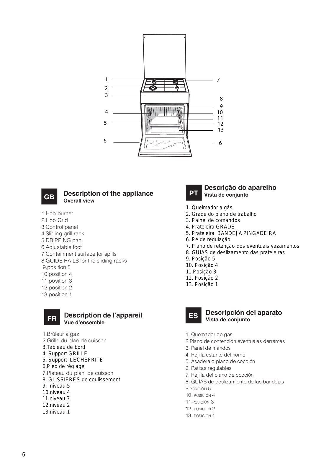
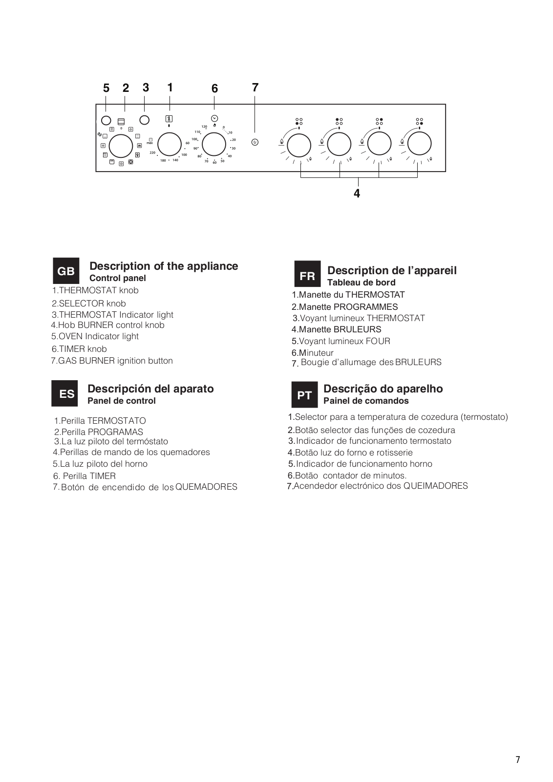
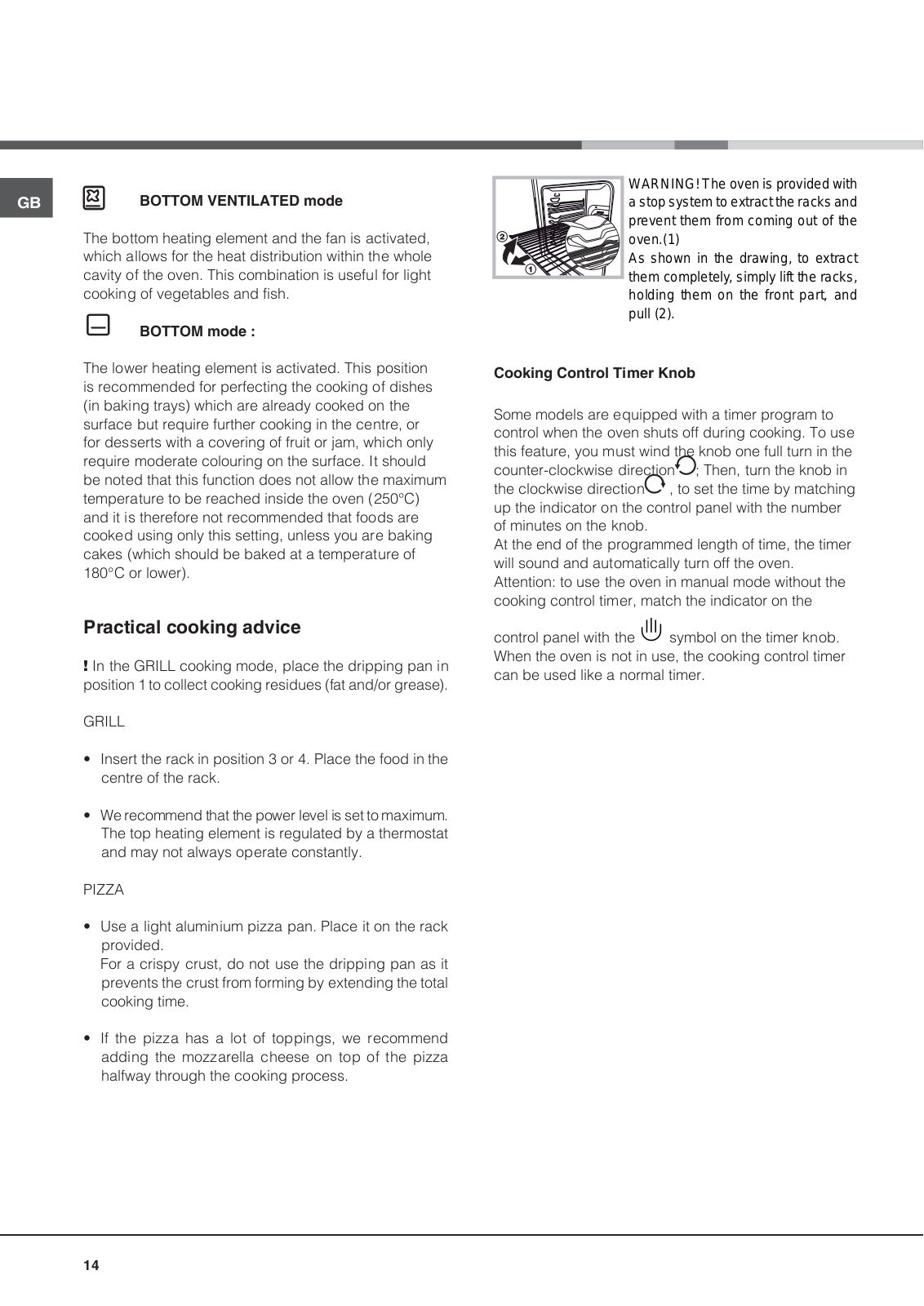
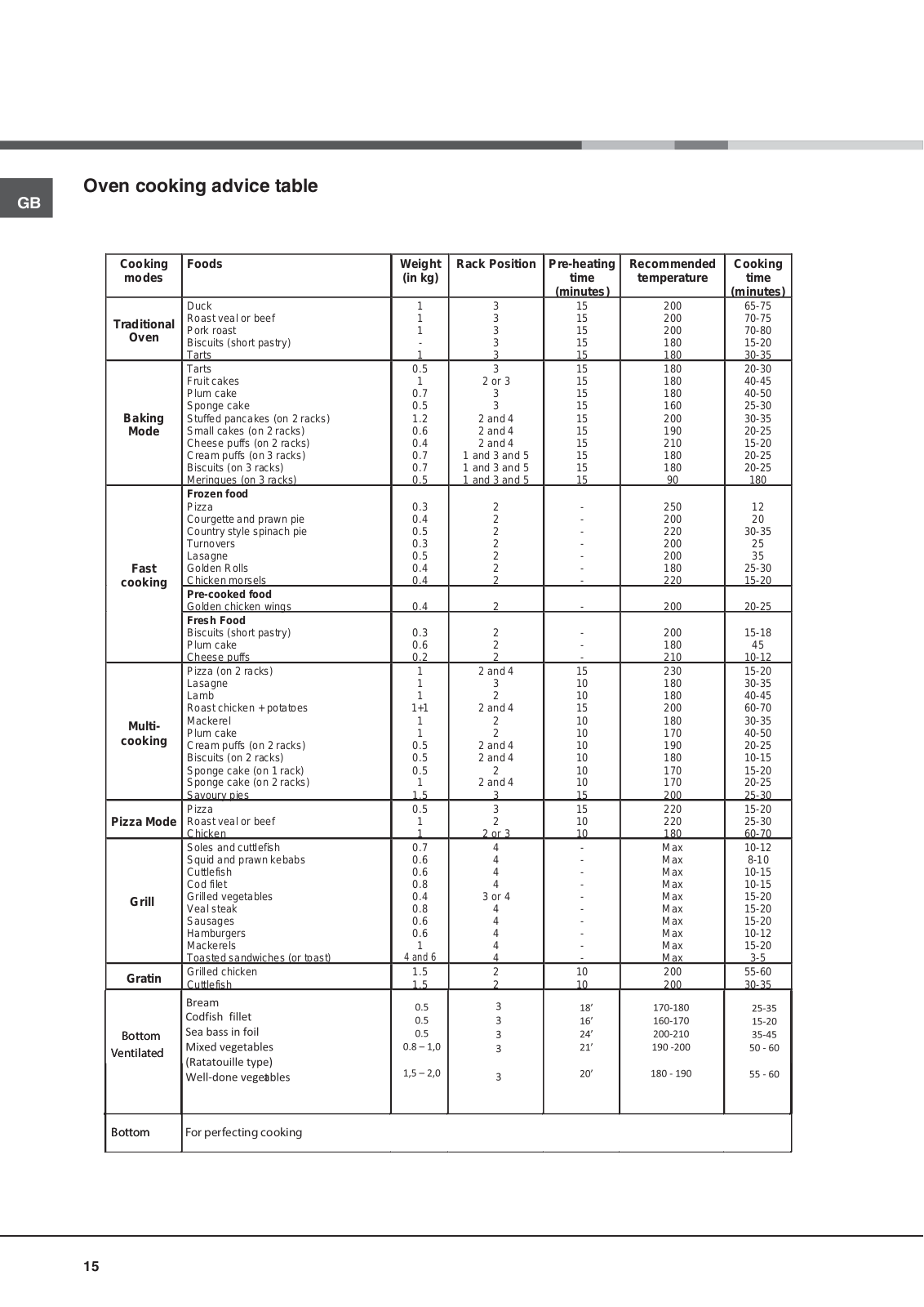
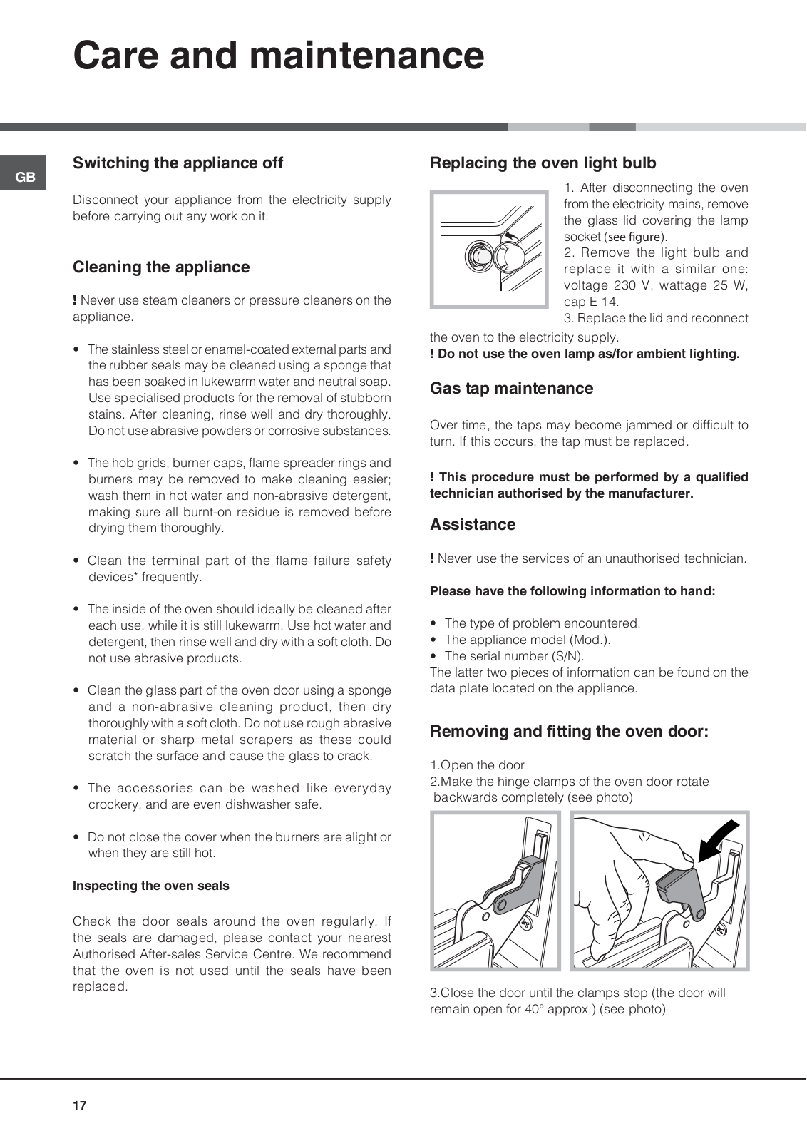
Hotpoint A6TMH2F IL User Manual
...
Hotpoint User Manual
Download
Specifications and Main Features
Frequently Asked Questions
User Manual
Download
Loading...
+
50
hidden pages
Unhide
You need points to download manuals.
1 point = 1 manual.
You can buy points or you can get point for every manual you upload.
Buy points
Upload your manuals
 Loading...