

Hoshizaki ROX-20TA-U Installation Manual

ISSUED: FEB. 29, 2000
REVISED: APR. 25, 2005
HOSHIZAKI
WATER ELECTROLYZER
MODEL
INSTRUCTION MANUAL
ROX-20TA-U

IMPORTANT
Only quali fied ser vi c e techn i cians shoul d attem pt to install, service or mai ntain
this water electrolyz er. No in stallation, ser vice or maintenanc e should be undertaken
until the techn ician has thoroughly read this Instruction M anual. Likewise, the owner/
manager should not pr o ceed to operate th e w ater electr olyzer until the i nst all e r
has in str uct ed the m on i ts pr oper op er ati on.
HOSHIZAKI provides th is manual primarily to assi st qual ified s ervice techni cians in th e
installation, maintenance and service of the water electrolyzer .
Should the reader have any questions or concerns which have not been satisfactorily
addressed, please call or write to the HOSHIZAKI Technical Support Department for
assistance.
HOSHIZAKI AMERICA, INC.
618 Highway 74 South
Peachtree City, GA 30269
Attn: HOSHIZAKI T echnical Support Department
Pho ne : 1-800-233 -1940 Technical Servic e
(770)487-2331
Fax: (770)487-3360
Note: T o expedite assistance, al l correspondence/communication MUST include the following
information:
* Model Number
* Serial Number
* Complete and detailed explanation of the problem

* Please r eview th is manual. It shoul d be read carefully before the water electrolyz er is ins talled
and opera ted. Only qualifie d ser vice techni cians s hould i nst all , serv i c e and mainta i n t he
water electrolyz er. This manual should be made av ailable to the technician prior to inst allation,
main tenanc e or se rvi ce.
* Keep this manual with the water electrolyzer for later reference.
CONTENTS
I. S PEC IFIC AT IONS------------ ---------- ---------- ---------- -------- ---------- ---------- ---------- -------1
1. NAMEPLATE RA TING------------------------------------------------------------------------------1
2. DIMENSIONS/CONNECTIONS ------------------------------------------------------------------2
II. C ONSTRUCTION ---------------------------------------------------------------------------------------3
1. GENERAL---------------------------------------------------------------------------------------------3
2. CO NTRO L PANEL ----- ------ ------ ------ ------ ---- ------ ------ ------ ------ ------ ------ ---- ------ ---5
3. DISP LAY PANE L ------- ---- ---- -- ---- ---- ---- ---- ---- -- ---- ---- ---- ---- ---- -- ---- ---- ---- ---- ---- ---6
4. C ONT ROL BOX----- ------ ------ ------ ------ ---- ------ ------ ------ ------ ------ ------ ---- ------ ------ -7
5. REMOTE CONTROLLER (OPTION) ------------------------------------------------------------8
6. WA TER T ANK FLOA T SWITCHES (OPTION) ------------------------------------------------8
7. OUTLET V AL VES (OPTION) ---------------------------------------------------------------------9
8. ACCESSORIES -------------------------------------------------------------------------------------9
III. INST ALLA TION AND OPERA TING INSTRUCTIONS----------------------------------------- 10
1. CHECKS BEFORE INSTALLATION ----------------------------------------------------------10
2. HO W TO REM OVE PANELS---------- ---- ---- ---- ---- ---- -- ---- ---- ---- ---- ---- -- ---- ---- ---- -10
3. LOCA TION ------------------------------------------------------------------------------------------ 10
4. ELECTRICAL CONNECTION ------------------------------------------------------------------ 11
5. INST ALLA TION OF WA TER SOFTENER (SOLD SEP ARATELY) AND
WATER FI LTER (SOL D SEPARA TE LY)---------- -- ---- ---- ---- ---- ---- -- ---- ---- ---- ---- ---12
[a] CHECKS BEFORE INSTALLATION------------------------------------------------------ 12
[b] LOCA TION -------------------------------------------------------------------------------------- 12
[c] SET UP ------------------------------------------------------------------------------------------ 12
[d] E LECT RICA L CON NEC TION --------- -------- -------- -------- -------- ------ -------- -------12
[e] W A T ER SU PPLY AND PLU MBIN G C ONNE CTIO NS ----- ------ ------ ---- ------ -----13
6. INSTALLA TION OF REMOTE CONTROLLER (OPTION)-------------------------------- 14
[a] CHECKS BEFORE INSTALLATION------------------------------------------------------ 14
[b] LOCA TION -------------------------------------------------------------------------------------- 14
[c] SET UP ------------------------------------------------------------------------------------------ 15
[d] E LECT RICA L CON NEC TION --------- -------- -------- -------- -------- ------ -------- -------17
7. INST AL LA TION OF WATER T ANK FLOAT SWITCHES (OPTION) AND
WA TE R T ANK (SOLD SE P AR A TEL Y )---------- ---- ------ ------ ------ ------ ------ ---- ------ -17
[a] CHECKS BEFORE INSTALLATION------------------------------------------------------ 17
[b] LOCA TION -------------------------------------------------------------------------------------- 18
[c] SET UP ------------------------------------------------------------------------------------------ 18
PAGE
i

[d] ELECTRICAL CONNECTION --------------------------------------------------------------19
8. INST ALLA TI ON OF OUTLE T V ALVES (OPTION)------------------------------------------20
[a] CHECKS BEFORE INSTALLATION------------------------------------------------------ 20
[b] LOCA TION -------------------------------------------------------------------------------------- 20
[c] SET UP ------------------------------------------------------------------------------------------21
9. WATER SUPPL Y AND PLUMBING CONNECTIONS------------------------------------- 22
[a] UNIT WITH REMOTE CONTROLLER, WATER SOFTENER &
WA TER FIL TER -------------------------------------------------------------------------------- 22
[b] UNIT WITH WATER T ANK, WATER SOFTENER & WATER FILTER ------------- 25
10. OPERATION M ODE S ETTIN G-------- -------- -------- -------- -------- ------ -------- -------- ---29
1 1. F INA L CH ECK LI ST-------- ------ ------ ------ ------ ------ ------ ---- ------ ------ ------ ------ ------ -32
IV . CHECKS BEFORE OPERATION ---------------------------------------------------------------33
1. CHECKING AMOUNT OF REMAINING SAL T WA TER----------------------------------- 33
2. MA KING SALT WA TER ----------- ------ ------ ---- ------ ------ ------ ------ ------ ------ ---- ------ -33
3. PUR GIN G SALT WA TER SUPP L Y PUM P---------- ------ ------ ------ ------ ---- ------ ------ -34
V . OPERA TION-------------------------------------------------------------------------------------------35
1. START UP------------ ---- ---- -- ---- ---- ---- ---- ---- ---- -- ---- ---- ---- ---- ---- ---- -- ---- ---- ---- ---- -35
2. SH UT DOWN-------- -------- -------- ------ -------- -------- -------- -------- -------- -------- ------ ---36
VI. MAINT ENANC E ------------ ---------- -------- ---------- ---------- ---------- ---------- ---------- -----37
1. CHECKING pH AND A V AILABLE CHLORINE CONCENTRA TION ------------------- 37
2. FL USHI NG ALKALINE WA T ER PI PE------------ ------ ------ ------ ---- ------ ------ ------ -----37
3. CLEANING WATER LEVEL SEN SOR, SALT WATER FILTER AND
SALT WA TER T ANK------------------------------------------------------------------------------39
4. CHECKING WA TER SOFTENER ------------------------------------------------------------- 39
5. CHECKING WATER FIL TER-------------------------------------------------------------------- 40
6. EXTERIOR ------------------------------------------------------------------------------------------40
7. PREPARING WA TER ELECTROLY ZER FOR LONG STORAGE ---------------------41
VII. TR OUBLE SHOOTING ----------------------------------------------------------------------------42
1. WHEN ELECTROLYTIC CELL REPLACE LAMP IS ON -------------------------------- 42
2. WHEN ADD S ALT LAMP IS ON ------------ ---- -- ---- ---- ---- ---- ---- ---- -- ---- ---- ---- ---- ---42
3. WHEN SERVICE CALL LAMP IS ON -------------------------------------------------------- 43
[a] CONTA CT AUTHORIZED HOSHIZAKI SERVICE COMP ANY --------------------- 43
[b] CHECK BY USER ---------------------------------------------------------------------------- 44
4. PROBLEMS WITHOUT ALARM IND ICATION ---------------------------------------------- 45
VIII. DAIL Y INSPECTION SHEET -------------------------------------------------------------------- 46
ii
I. SPECIFICATIONS
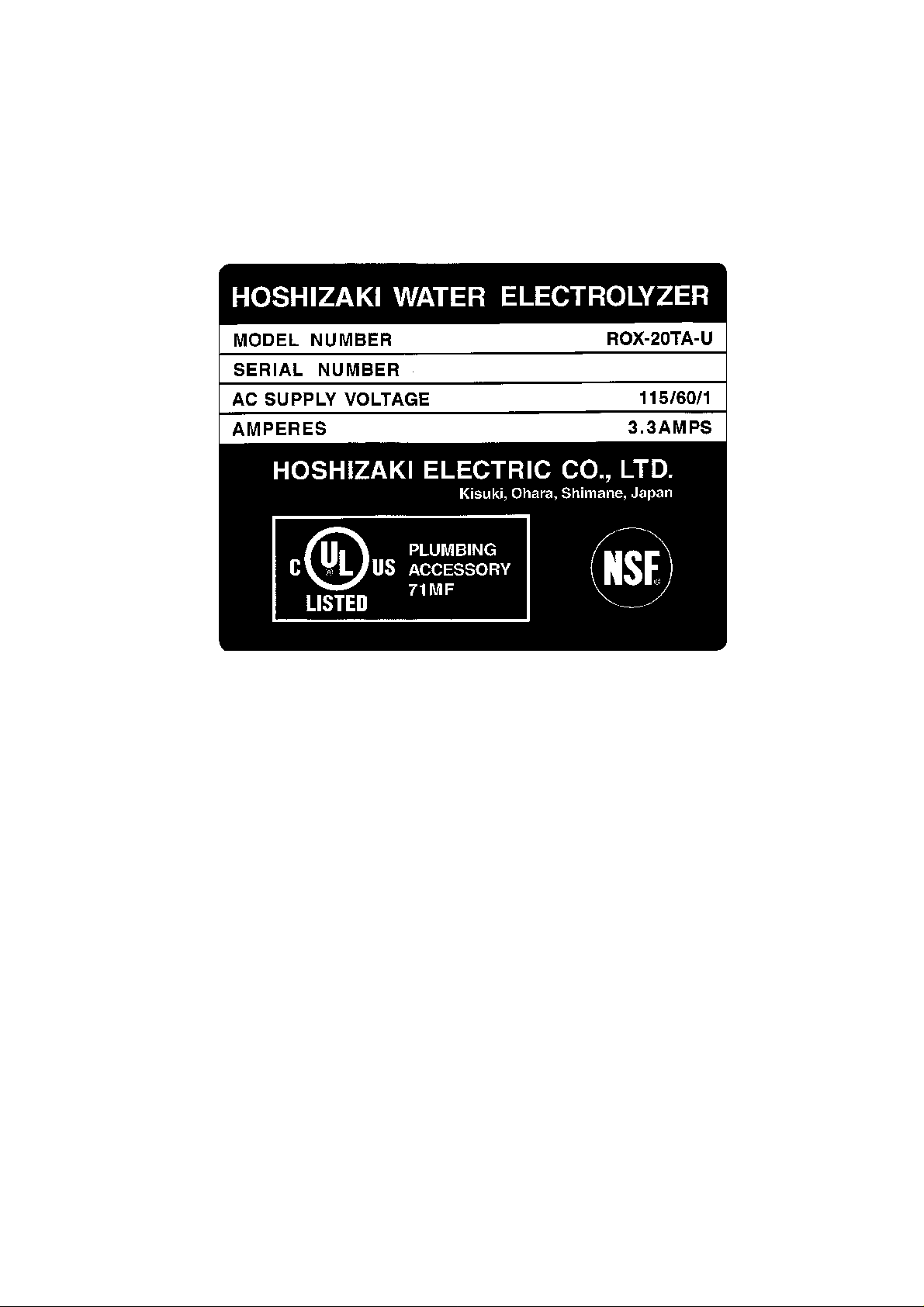
1. NAMEPLATE RATING
See the Nameplate for electrical specifications. This Nameplate
is located on the lower right hand side of the Rear Panel.
1
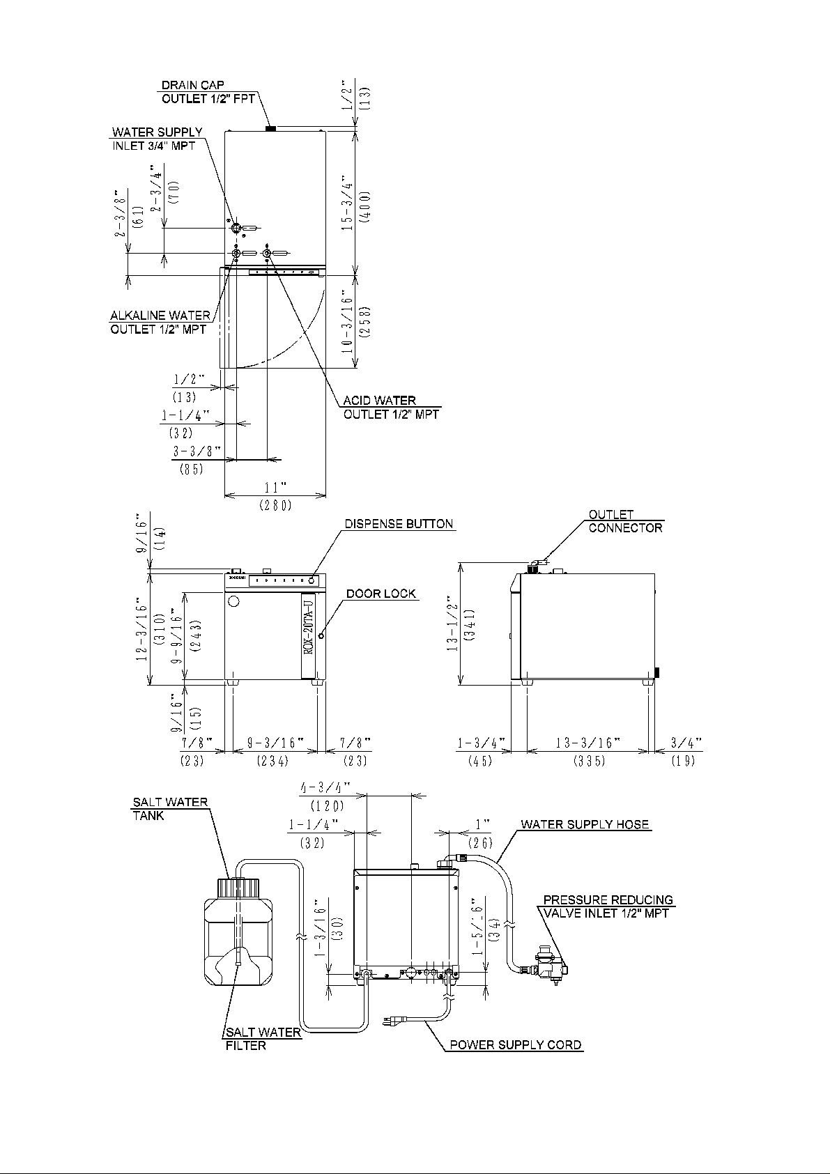
2. DIMENSIONS/CONNECTIONS
Unit: inch (mm)
2
II. CONSTRUCTION
1. GENERAL
[4]
[6] [5] [3]
[7] [2]
[8]
[17]
[16] [18]
[19]
[1]
[20]
[21]
[9] [15]
[10]
[1 1] [14]
[12]
[13]
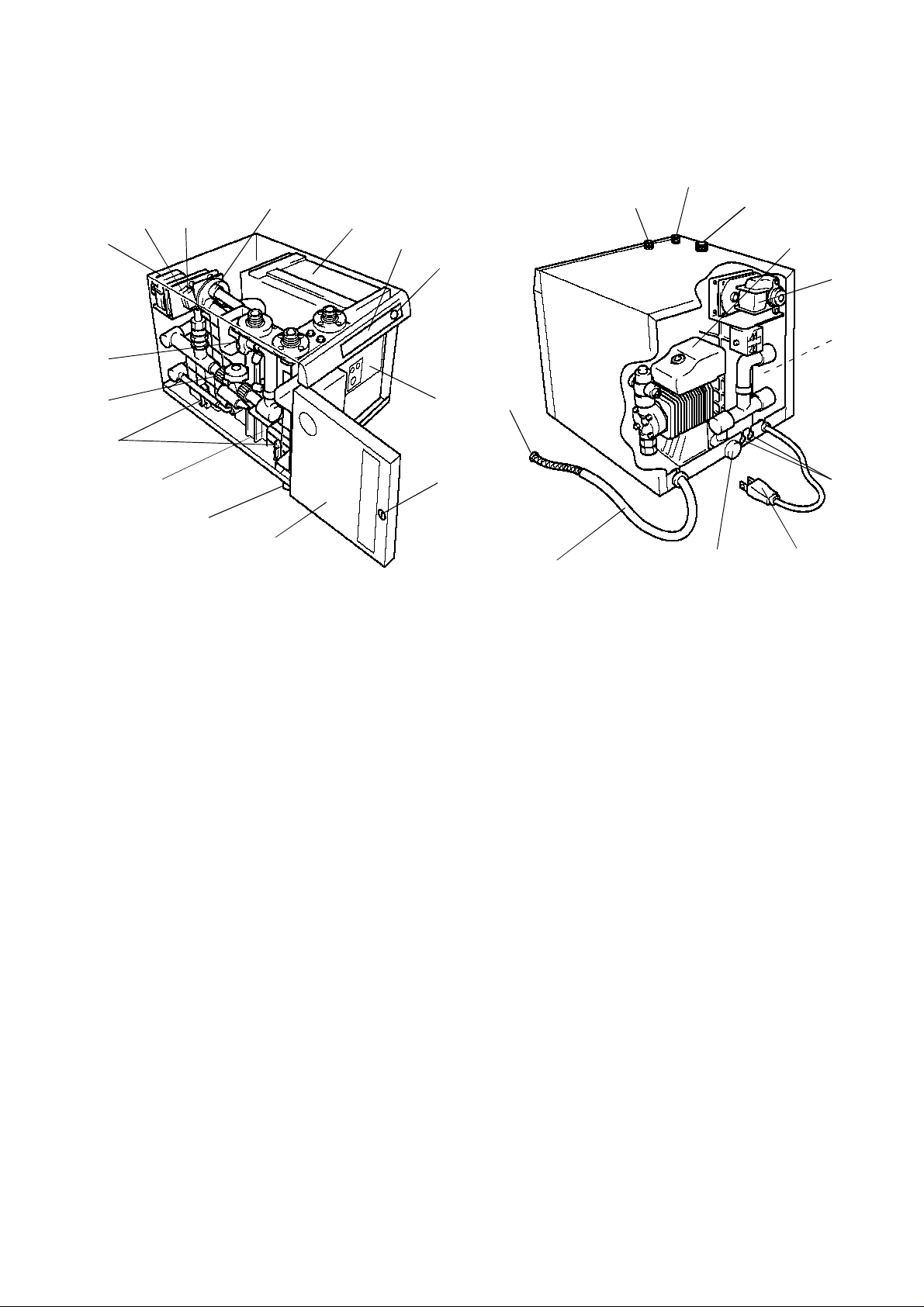
[1] Display Panel
See “II. 3 . DISPL A Y PANEL“.
[2] Lamp Boar d
Board wi th lam ps i ndi cat ing un it stat us .
[3] Control Box
See “II. 4. CONTROL BOX”.
[4] Flow Swit ching V a lve
Changes the flow direction of electrolytic water.
[5] Microswitch [Direction]
Senses th e di rec ti on of th e Fl ow Sw it chin g Valve.
[6] M icr osw it ch [ Loc atio n]
Senses t he l ocat io n of t he Flo w Sw itch in g V a lv e.
[7] Gear Motor
Rotates the Impeller inside the Flow Switching V alve.
[8] Water Valve
Suppli es po table wa ter to th e El ect roly tic Cell .
[9] Flow Rate Sensor
Senses p ota ble w a ter flow.
[10] Surg e Abs orber
Interrupts a temporary voltage surge.
[11] E lec tr oly ti c Ce ll
Electrolyzes diluted salt water and generates acid and alkaline water.
[12] Leg
Not adjustable.
[26]
[22]
[25] [24] [23]
3

[13] Door
Provi ded with Doo r Lock .
[14] Door Lock
Locks t he Door.
[15] Cont rol Pa nel
See “II. 2. CONTROL PANEL”.
[16] Acid Water Outlet
Dispenses acid wa ter during the normal operati on and alkaline water during the flushing
process.
[17] Alkaline Water Outlet
Dispenses alkali ne water during the normal operation and acid water during the flushing
process.
[18] Water Supply Inlet
Inlet for potable water supplied to the unit.
[19] Electromagnetic Metering Pump
Supplies salt water to the unit.
[20] Termin al Block
Used when the Water Tank (sold separately) is installed.
[21] Rear Panel (not shown)
Removed when the Water Tank Float Switches are connected to the T erminal Block or
the Remote Controller is connected to the Control Box.
[22] Blind Bushing
Removed when the Water Tank Float Switches are connected to the T erminal Block or
the Remote Controller is connected to the Control Box.
[23] Power Supply Co rd
Flexible cord with a grounding conductor and grounding type attachment plug.
[24] Drain Cap
Used for drai nin g the pipes .
[25] Salt Water Hose
Made of PVC.
[26] Salt Water Filter
Removes foreign substances in salt water.
4
2. CONTROL PANEL
[1]
[2]
[3]
[4]
[5]
[6]
[10]
[9]
[7] [8]
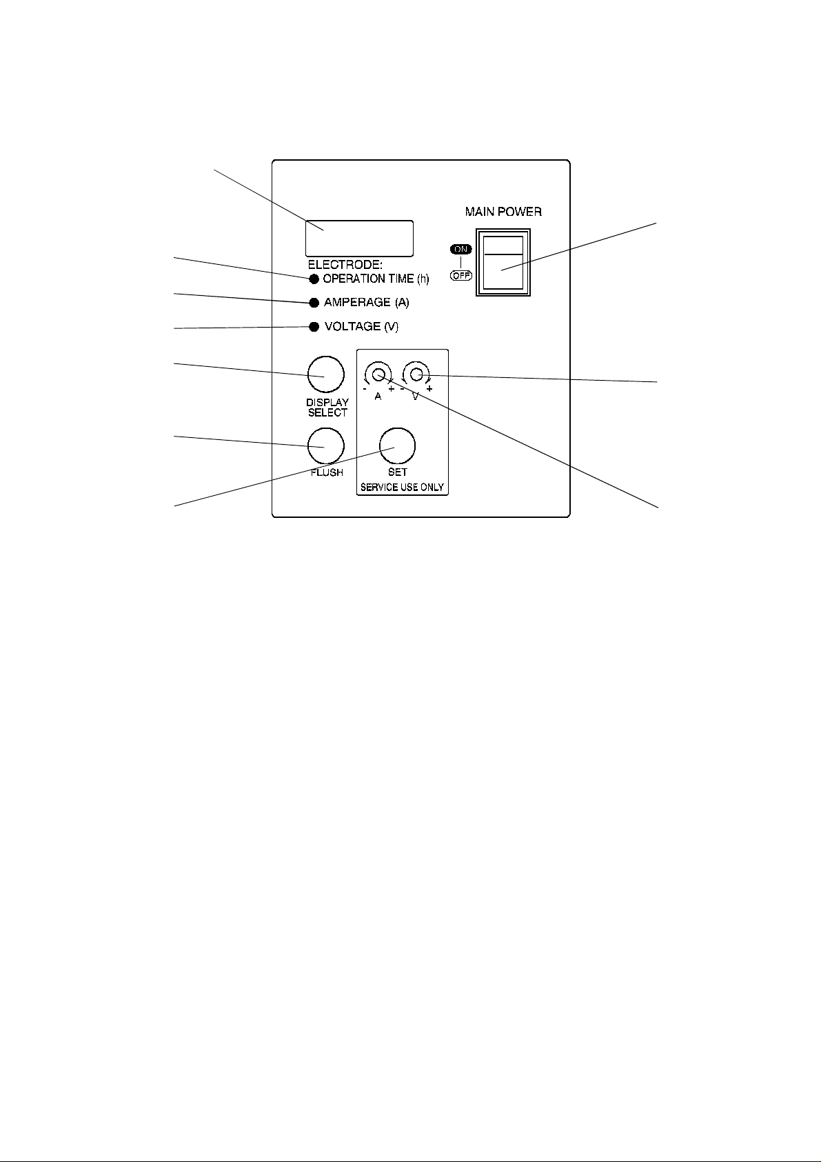
[1] Display Window
Displays the operati on tim e, amperag e or voltage during the normal operation and
error code s in cas e of troubl e.
[2] Operation Time Lamp
Display Window displays operation time (h) when this lamp is on.
[3] Ampera ge Lamp
Dis play Window di splay s ampe rag e (A ) w hen t hi s lam p is on.
[4] Voltage Lamp
Display Window displays voltage (V) when this lamp is on.
[5] Display Select Button
Swi tche s th e di spl ay of th e Di sp lay Window.
[6] Flush Button
Funct io ns as a s wit ch to flus h t he pipe s b ey on d the ac id and al kali ne wa ter ou tl ets .
[7] Se t Button
Only qualified service personnel or installer may press this button to adjust various set
values.
[8] Am pera ge C ont rol Volume
Only qualified service personnel may turn this control to change the set amperage.
[9] Voltage Control Volume
Only qualified service personnel may turn this control to change the set voltage.
[10] Power Switc h
Turns the uni t On and Off.
5
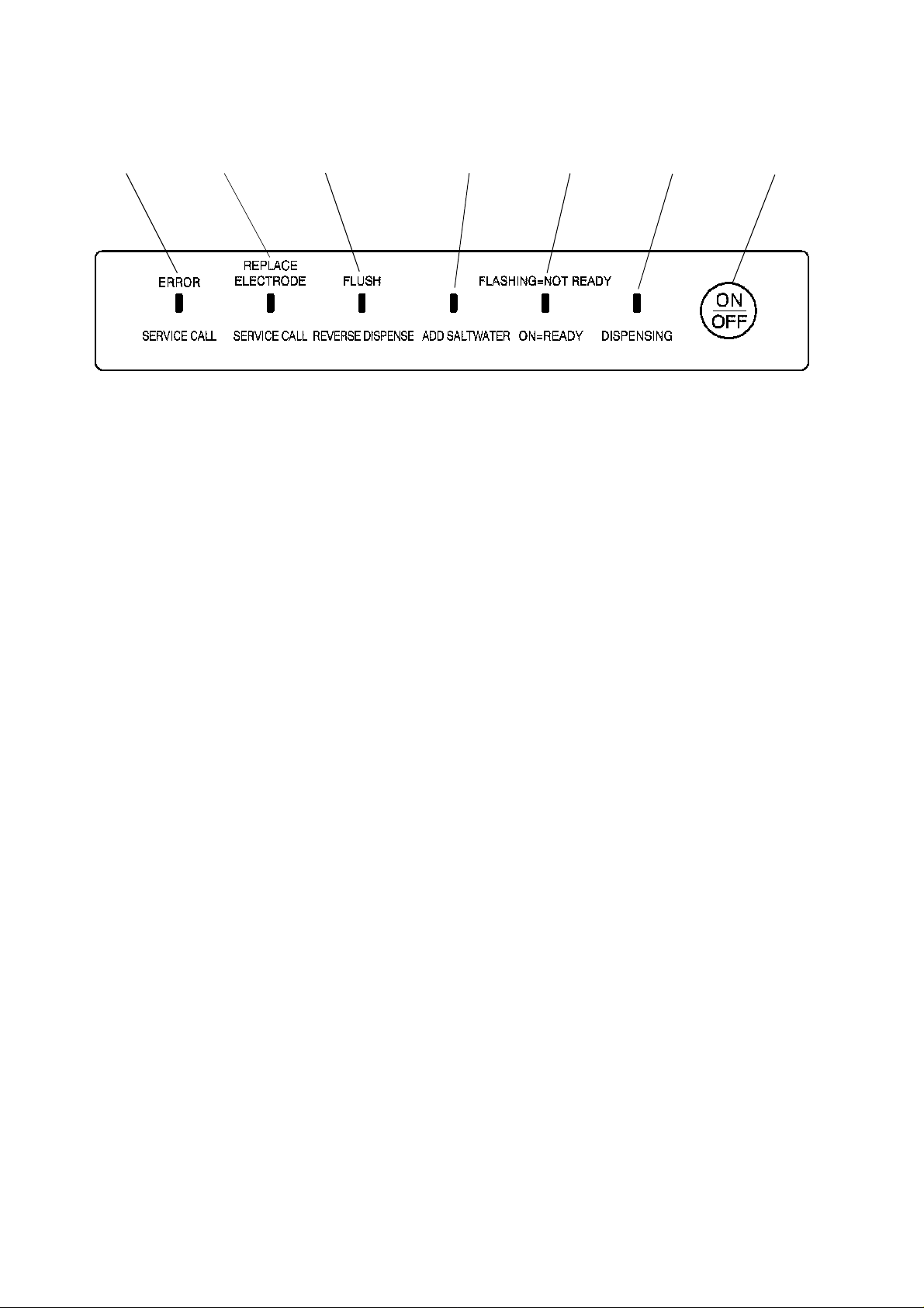
3. DISPLAY PANEL
[7] [6] [5] [4] [3] [2] [1]
[1] Dispense Button
Starts and stops dispensing electrolytic water.
[2] D i s pe nsing Lam p ( Green)
Indicates that the unit is producing water.
[3] Ready Lamp (Green)
Flashes until the desired settings are achieved and stays on when the unit is dispensing
electrolytic water.
[4] Ad d Sal t Wate r Lamp ( Re d)
Indicates that the Salt Water T ank level is too low.
[5] F lush Lamp (Red )
Stays on during the flush operation. Indicates that the unit is in flush cycle.
[6] E lectr ol yt ic Cel l R epl ac e Lamp (Re d)
Indicates that the cell life is near completion. Flashes continuously from 2900 hours to
3000 hours and stays on after 3000 hours.
[7] Service Call Lamp (Red)
Indicates that there is trouble detected.
6
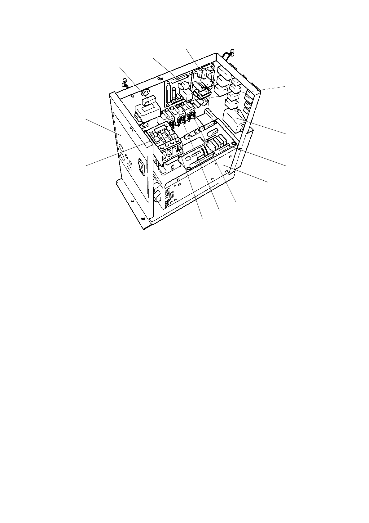
4. CONTROL BOX
[3]
[4]
[5] [10]
[1]
[2]
[12]
[1 1]
[9]
[8]
[7]
[6]
[1] Switching Regulator
Suppl ies po wer to s t art the Pr ogr amm able C ontr oll er, etc.
[2] Noise B oar d
Board to remove noise in the unit.
[3] C urr ent Se nso r
Reads amperage in the Electrolytic Cell.
[4] Oper ation Board
Board wi th swi tc hes t o op er at e the Cont rol Pa nel , et c.
[5] Magnetic Contactor
Switches polarity of the Electrolytic Cell.
[6] Relay 1
For [ 10] DC Pow er Supp ly.
[7] Relay 2
Controls the water level in the Water T ank.
[8] Relay 3
Swi tches the elec tr olyti c wa ter di spla y of the R emote C ontro lle r .
[9] DC Power Supply
Power supply for cells to generate electrolytic water.
[10] Programmable Controller
Manages all controls of the unit.
[11] Noise Filter
Removes noise from 1. [19] Electromagnetic Metering Pump.
[12] Ferrite Core (not shown)
Removes noise in the unit.
7
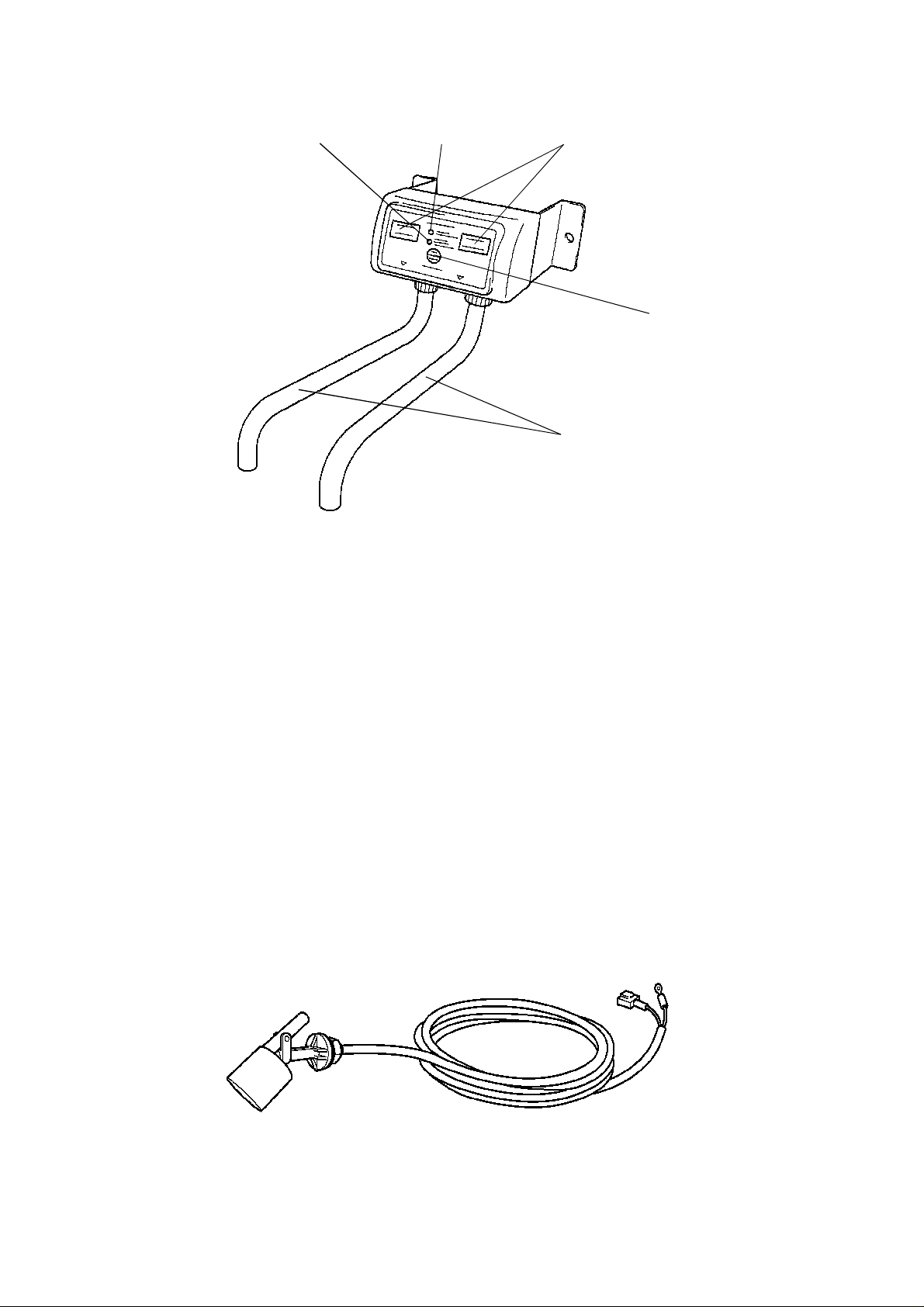
5. REMOTE CONTROLLER (OPTION)
[1] [2] [3]
[1] Ready Lamp (Green)
Flashes until the de sired settings ar e achieved and stay s on when the unit i s dispensing
electrolytic water.
[2] Add Salt Water Lamp (Red)
Indicates that the Salt Water T ank level is too low .
[3] Ele ctro lyti c Water Lamp (Green )
The upper lamps will function during the normal operation. Alkaline water is dispensed
from the left outlet and acid from the right . The lower lamps will function during the flush
operation only . Acid water is dispensed from the left outlet and alkaline water from the
right.
[4] Dis pense But ton
St art s and sto ps dis pe nsing el ectr olyt ic w ater.
[5] Electrolytic Water Outlet
Tr anspo rts el ectr oly tic wa ter .
[4]
[5]
6. WATER TANK FLOAT SWITCHES (OPTION)
Includes the Upper and Lower Acid Water T ank Level Float Switches and Upper and Lower
Alkaline Water T ank Level Float Switches.
8
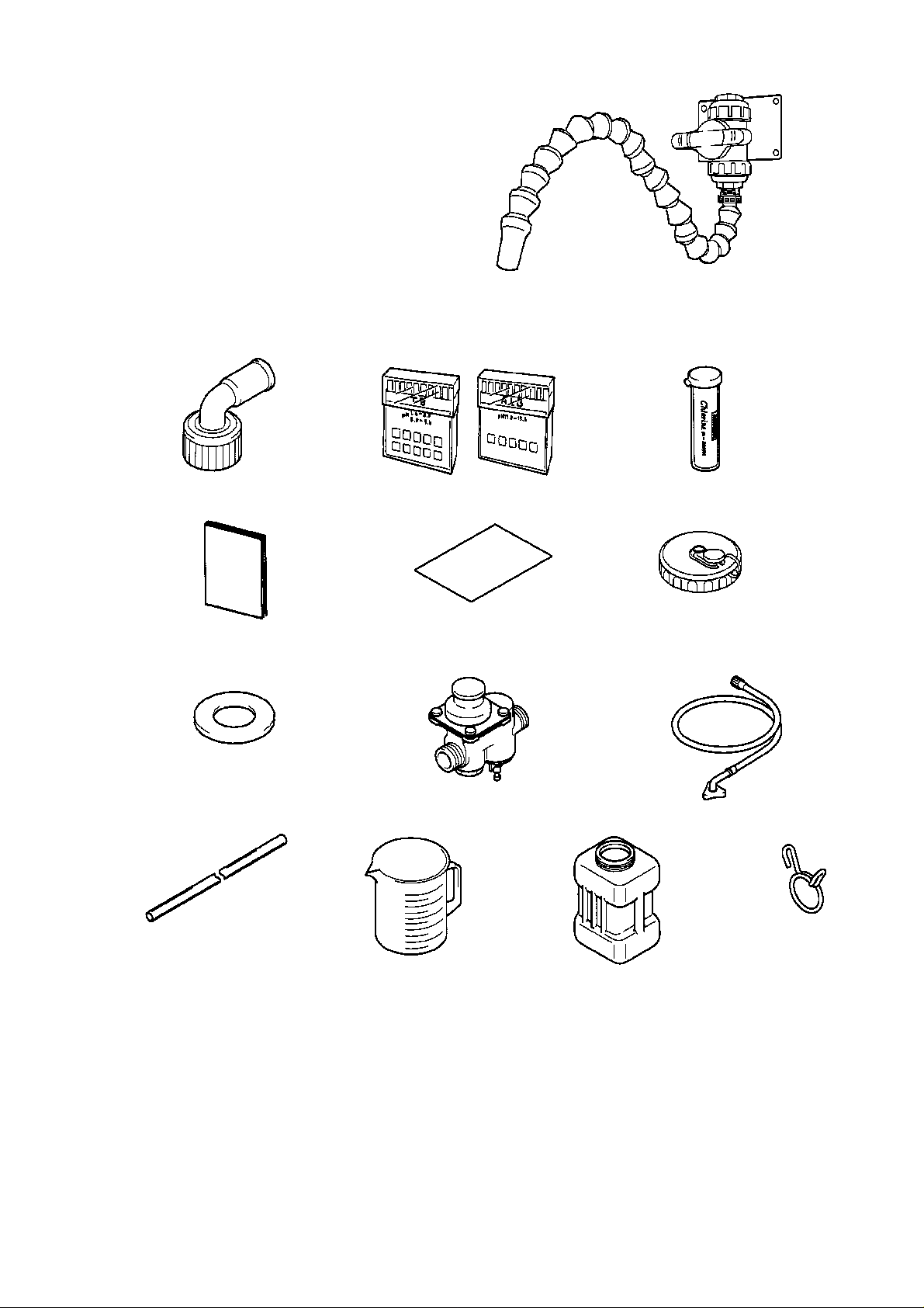
7. OUTLET VALVES (OPTION)
Connected with the Electrolytic Water Outlets
(for acid and alkaline water outlets) on the
Water Tank. U se as ne ede d.
8. ACCESSORIES
Connectors pH Testers Chlorine Tester
Instruction Manual Instruction Sheet Cap
Gaskets Press ure Redu cing V alv e Water Suppl y H ose
Braided Hoses Salt Measu ri ng Cup Sal t Wat er Tank Clamps
9
III. INSTALLATION AND OPERATING INSTRUCTIONS
1.CHECKS BEFORE INSTALLATION
IMPORTANT
1. Remov e ship pi ng car ton an d tape( s). If packag i ng ma teri al is left in the wat er
electrolyzer, it will not work properly.
2. Use potable water . If water other than potable water is used, it may clog pipes,
cause poor performance, etc.
3. Purchase either the Remote Controller (Option) or Water Tank Float Switch
(Option).
4. Install a w ater softener and water filter (sold separ ately) on the water electrolyzer
to improve machine performance and prevent electrolytic cell damage, etc.
1) Be sure not to damage the panels when installing the water electrolyzer.
2) Remov e the pa ckag e cont aini ng the ac cess orie s.
3) See the Nameplate on the Rear Panel and check that the voltage supplied corresponds
with the v oltag e spe cifie d on the Nam eplat e.
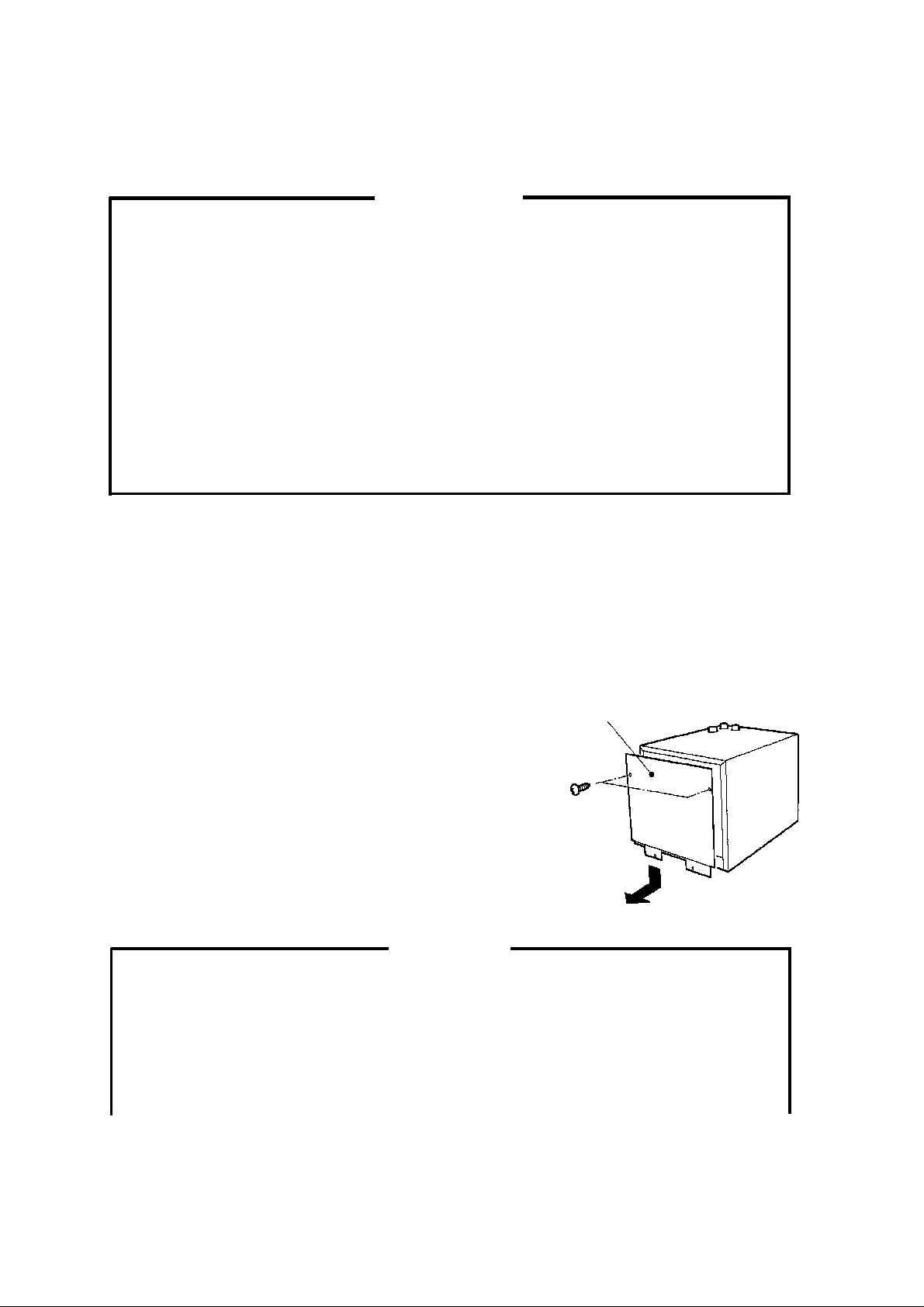
2. HO W TO RE M OV E PANELS
a) Rear Panel --------- Remove the screws.
Lift off slightly and pull toward you.
3. LOCATION
Rear Panel
Fig. 2
W ARNING
1. This water electrolyzer is not intended for outdo or use. Normal operat ing ambient
temperature should be within +40°F to 95°F (+5°C to +35°C); Normal operating
water temperature should be within +40°F to 85°F (+5°C to +30°C). Operation
of the water electrolyzer for exte nded periods outside of these normal
temperature ranges may affect performance.
10
2. Do not install the unit where exposed to humidity or splashing water. Reduction
in insulation property may cause an electric leak or shock. Locations should be
at least 6” above the floor to avoid splashing water during kitchen cleaning
operations.
3. Install adequate ventilating system. Hydrogen gas or chlorine gas may cause
health problems.
CAUTION
1. T o prevent damage to the unit, do not move the unit with the Door open.
2. The uni t shou ld not be subme rge d in wate r or become w et.
3. Use glass, plastic or stainless steel containers for electrolytic water . Acid water
may corrode metal.
For be st op erat in g r esul ts :
* The water electr olyzer should not be locat ed next to ovens, grills or other high heat producing
equipment.
* Location should provide a firm and level foundation for the equipment.
* Allow 6” clearance at rear, sides and top for proper performance and ease of maintenance
and/or serv ice .
* Install the unit in a well-ventilated area. Use fans with diameter over 6 inches (standard air
3
flow rate: 270ft
/min (450m3/h)) if necessary.
4.ELECTRICAL CONNECTION
W ARNING
1. This water electrolyzer must have a separate power supply or receptacle of
proper capacity. Branching off the Power Cord, using an extension cord or
sharing a s i ng le power supply wit h ot her app l ian ces may res ul t in an electri c
shock, heat generation or fire.
2. The water electrolyzer requires a ground that meets the national and local
electrical code requirements. T o prevent possible electrical shock to individuals
or exte nsive damage t o eq uipment, plug the electr ol y zer only i nto a pr ope rl y
grounded electrical outlet.
11

CAUTION
The maximum allowable voltage variation should not exceed ±10 percent of the
rated vo lta ge . O per at ion of the unit outside of this ra ng e m ay ca use damage t o
the unit or reduction of the performance.
* Usu all y an elect ri cal perm it and se rv ic es of a li ce nsed e lec tr ici an ar e r equi red .
5. INSTALLATION OF WATER SOFTENER (SOLD SEPARATELY) AND
WATER FILTER (SOLD SEPARATELY)
[a] CHECKS BEFORE INSTALLATION
1) Unpack and remove shipping carton, tape(s) and other packaging material(s).
2) Check that all the necessary accessories are included.
3) Follow the Instruction Manual for the Water Softener and the Water Filter .
[b] LOCATION
* Install the Water Softener and Water Filter under the same ambient temperature and water
temp erat ure c ondi tions as t he wat er elect rol yze r .
* Follow the Instruction Manual for the Water Softener and the Water Filter.
[c] SET UP
1) Install the valves and pipes following the Instruction Manual for the Water Softener and the
Water Fi lter .
2) Install a water pressure gauge on the pipe of the primary side of the Water Softener and
secondary side of the Water Filter.
[d] ELECTRICAL CONNECTION
W ARNING
1. This so ften er m ust h ave a s ep arat e p ower su ppl y or rece pt acle o f p rope r
capacity. Branching off the Power Cord, using an extension cord or sharing a
single power supply with other appliances may result in an electric shock, heat
generation or fire.
12
 Loading...