

Page 1

SERVICE MANUAL
FOR MODEL RM-10
Page 2
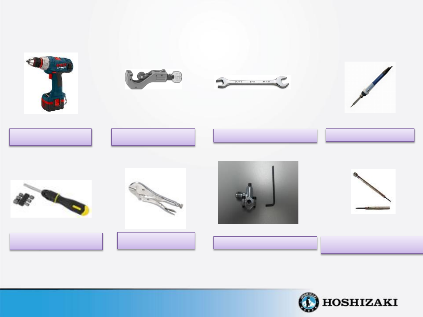
REQUIRED TOOLS
CORDLESS DRILL
SCREWDRIVER SET WITH
9/32” SOCKET
COPPER CUTTING TUBE
VISE GRIP
1/2” OPEN WRENCH
PIERCING VALVE
SOLDERING IRON
PRECISION FLAT BLADE SLOTTED
SCREWDRIVER
Page 3
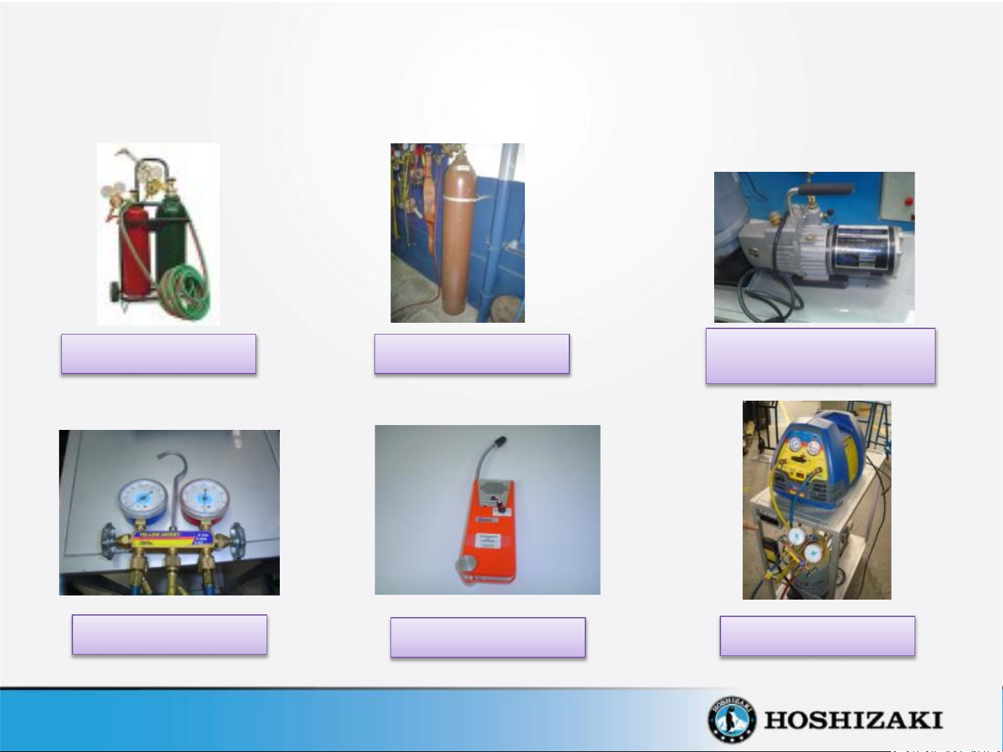
REQUIRED EQUIPMENT
OXY-ACETYLENE
EQUIPMENT
MANIFOLD HIGH & LOW
GAUGE PRESSURE KIT
DRY NITROGEN TANK
LEAK DETECTOR
VACUUM PUMP WITH GAUGE
METER WITH AN ACCURACY
IN MICRONS
REFRIGERANT RECOVERY
MACHINE
Page 4

CONTENTS
• Instructions to replace LED Power Supply.
• Instructions to replace LED strips lights.
• Instructions to replace condenser fan motor.
• Instructions to replace evaporator fan motor.
• Instructions to replace electronic thermostat.
• Instructions to replace thermostat ambient sensor.
• Instructions to replace starting relay, overload protector and starting capacitor.
• Instructions to replace compressor.
• Instructions to replace door.
Page 5
DISCONNECT UNIT FROM POWER SUPPLY BEFORE DOING ANY SERVICE
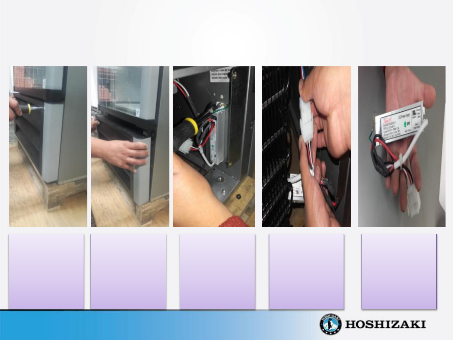
Instructions to Replace LED Power Supply.
1. Unscrew the four
screws that hold
in place the front
grill , using a
Phillips
screwdriver # 2
2. Pull out the front
grill .
3. In order to
remove the
Power Supply,
unscrew the two
screws that hold
it in place using
a Phillips
screwdriver # 2.
4. Disconnect the
Power Supply’s
electrical
connector.
5. To install the new
Power Supply
reverse the
previous steps.
Page 6
DISCONNECT UNIT FROM POWER SUPPLY BEFORE DOING ANY SERVICE
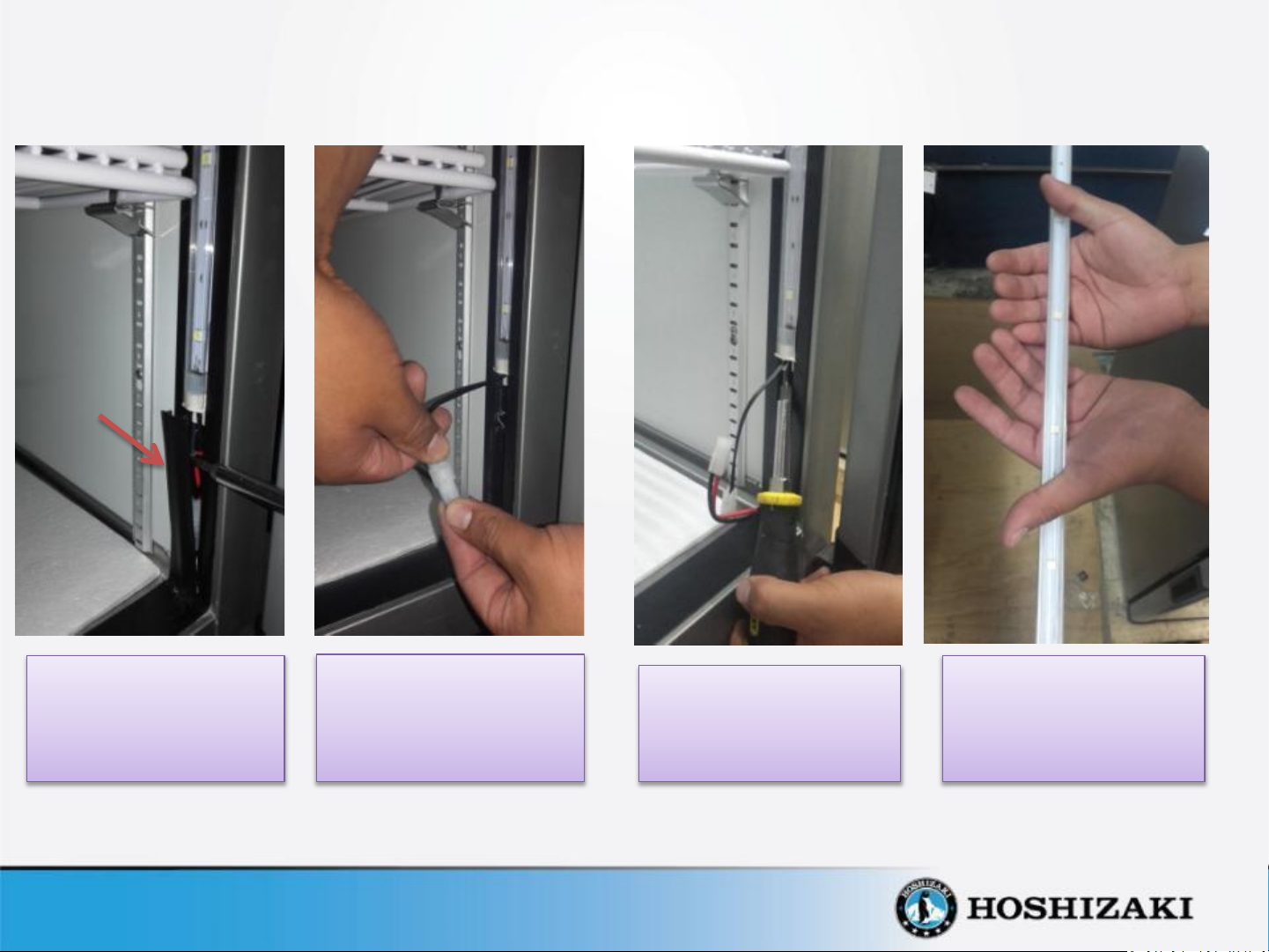
LED cover
profile
Instructions to Replace LED Strips.
1. Use a slotted
screwdriver to pull out
the LED cover profile.
2. Disconnect the LED
electrical connector.
3. Use a slotted
screwdriver to pull out
the LED strip.
4. To install the new LED
strip reverse the
previous steps.
Page 7
DISCONNECT UNIT FROM POWER SUPPLY BEFORE DOING ANY SERVICE
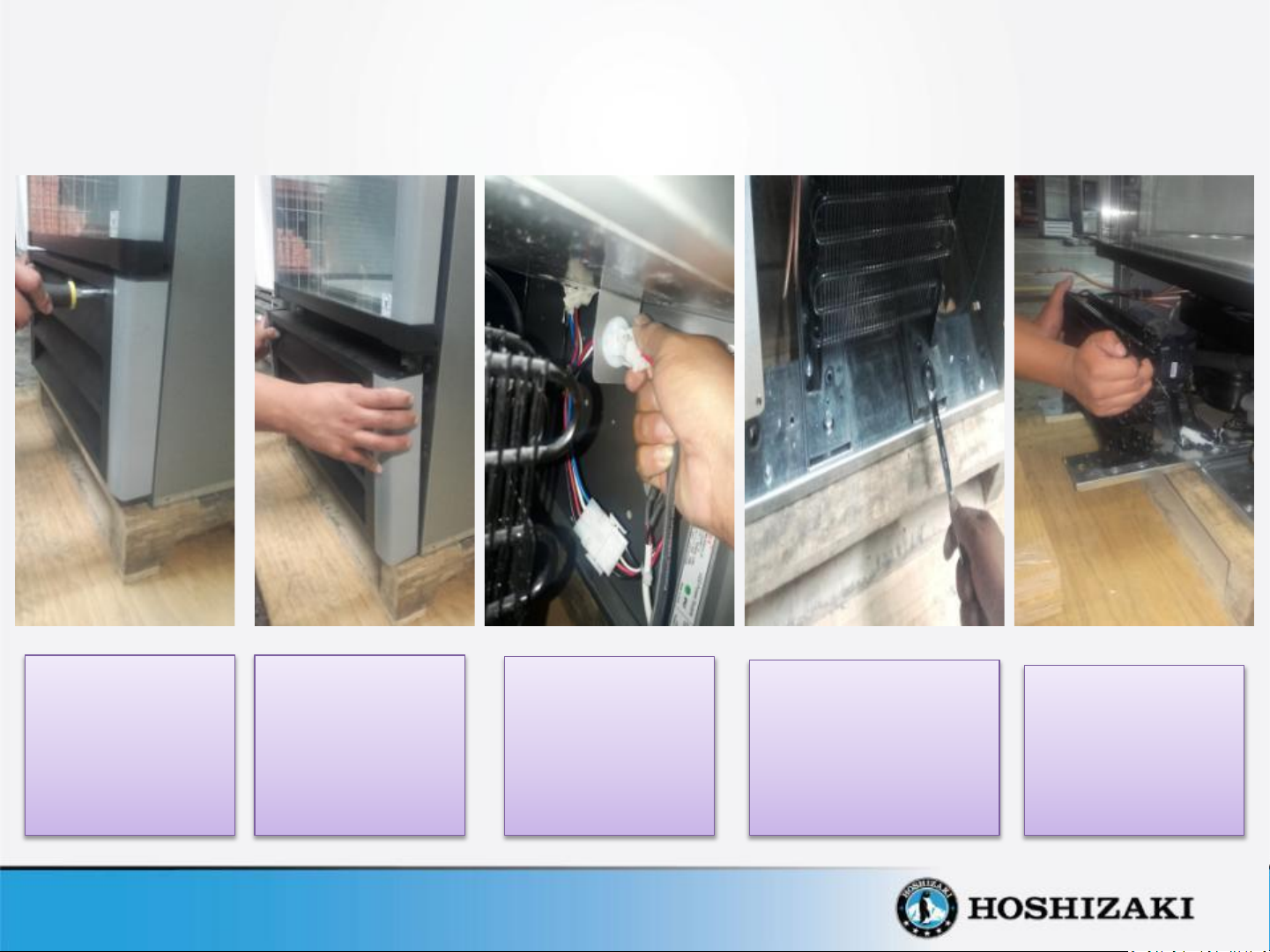
Instructions to Replace Condenser Fan Motor
1. Unscrew the four
screws that hold
in place the front
grill , using a
Phillips
screwdriver # 2
2. Pull out the front
grill .
3. Disconnect the
Tyco electrical
connector of
condensing unit.
4. Remove the two bolts
that hold in place the
rails using a 1/2”
open wrench. These
rails support the
condensing unit.
5. Pull out the
condensing unit
from the base of
the cabinet.
Page 8
DISCONNECT UNIT FROM POWER SUPPLY BEFORE DOING ANY SERVICE
Instructions to Replace Condenser Fan Motor
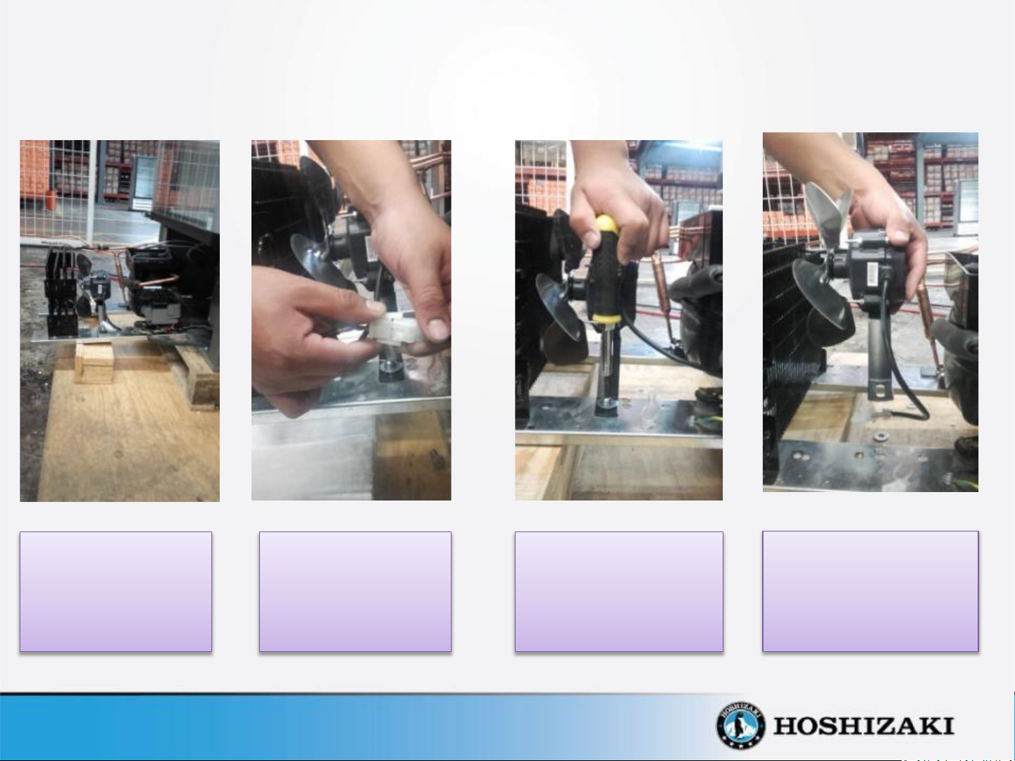
6. The condensing unit
can be removed all
the way out for
easier service.
7. Disconnect the Tyco
electrical connector
of the condenser
fan motor.
8. Unscrew the two
screws that hold in
place the base motor
to the rails using a
Phillips screwdriver # 2
9. Remove the condenser
fan motor by pulling it
out
Page 9
DISCONNECT UNIT FROM POWER SUPPLY BEFORE DOING ANY SERVICE
Instructions to Replace Condenser Fan Motor
10. Remove the bolt that hold in
place the fan blade to the fan
motor using a 9/32” socket
screwdriver.
11. Unscrew the two screws
that hold in place the base
motor to the fan motor
using a 9/32” socket
screwdriver.
12. To install the new
condenser fan motor
reverse the previous steps.
Page 10

DISCONNECT UNIT FROM POWER SUPPLY BEFORE DOING ANY SERVICE
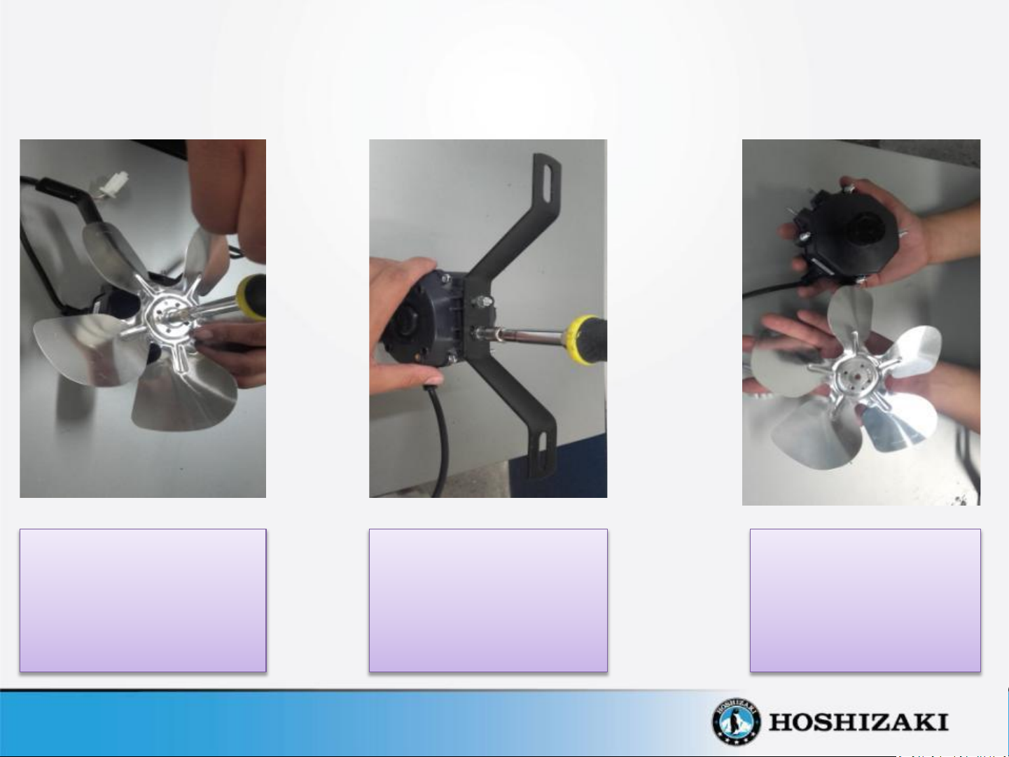
Fan Guard
Instructions to Replace the Evaporator Fan Motor.
1. Unscrew the four screws that hold in
place the fan guard on the air baffle
using a Phillips screwdriver # 2.
2. Remove the bolt that holds in place
the fan blade to the fan motor
using a 9/32” socket screwdriver.
3. Unscrew the four screws that hold in
place the support base motor to the
top of cabinet using a Phillips
screwdriver # 2.
Page 11

DISCONNECT UNIT FROM POWER SUPPLY BEFORE DOING ANY SERVICE
Instructions to Replace the Evaporator Fan Motor.
4. Disconnect the Tyco electrical
connector of the evaporator fan
motor located in the top of cabinet.
5. Unscrew the three screws that hold
in place the support base motor to
the fan motor chassis using a 9/32”
socket screwdriver .
6. To install the new evaporator fan
motor reverse the previous steps.
Page 12

DISCONNECT UNIT FROM POWER SUPPLY BEFORE DOING ANY SERVICE
Instructions to Replace The Electronic Thermostat.
1. Remove the front
frame of the
thermostat using
your fingers.
2. Turn 90° both screws to loosen
their cams and the front panel will
detach . Then, proceed to remove
the thermostat from the panel, by
keeping it horizontally.
3. Disconnect the
connectors located
in the back of
thermostat. .
4. To install the new
electronic
thermostat reverse
the previous steps.
Page 13

DISCONNECT UNIT FROM POWER SUPPLY BEFORE DOING ANY SERVICE
Instructions to replace Ambient Sensor.
1. Remove the front
frame of the
thermostat using
your fingers.
2. Turn 90° both screws to loosen
their cams and the front panel will
detach . Then, proceed to remove
the thermostat from the panel, by
keeping it horizontally.
3. Disconnect the
connector of the
ambient sensor
located on the back of
the thermostat, shown
in the picture.
4. Unscrew the two screws
that hold the wires in
place of the ambient
sensor using a precision
flat blade slotted
screwdriver.
Page 14

DISCONNECT UNIT FROM POWER SUPPLY BEFORE DOING ANY SERVICE
Instructions to replace Ambient Sensor.
5. Unscrew the two screws that hold in
place the light switch support plate on
the baffle using a Phillips screwdriver # 2 .
6. Pull out the ambient sensor from its
plastic clip support.
7. To install the new ambient sensor
reverse the previous steps.
Page 15

DISCONNECT UNIT FROM POWER SUPPLY BEFORE DOING ANY SERVICE
Instruction to Replace Starting Relay, Overload Protector and Starting Capacitor.
1. Unscrew the four
screws that hold
in place the front
grill using a
Phillips
screwdriver # 2
2. Pull out the front
grill.
3. Disconnect the
Tyco electrical
connector of the
condensing unit.
4. . Remove the two
bolts that hold in
place the rails using a
1/2” open wrench.
These rails support
the condensing unit.
5 Pull out the
condensing unit
from the base of
the cabinet.
Page 16

DISCONNECT UNIT FROM POWER SUPPLY BEFORE DOING ANY SERVICE
Instruction to Replace Relay, Overload Protector and Starting Capacitor.
.
6. The condensing unit can be
removed all the way out for
easier service.
7. Insert a flat screwdriver in the slot of
the plastic electrical box to remove it
from the compressor. Use the flat
screwdriver as a pry bar to push the
box downward.
8. At the same time that the plastic
electric box is being pushed
downward with the slotted
screwdriver, hold the box with the
other hand and pull it out
downward.
Page 17

DISCONNECT UNIT FROM POWER SUPPLY BEFORE DOING ANY SERVICE
Instruction to Replace Relay, Overload Protector and Starting Capacitor.
Overload protector
Overload protector
wires connection
Start Relay
LOCATION OF ELECTRICAL CONNECTIONS
Starting Capacitor
Ground wire .
Start Relay wire
connections
Starting capacitor wires
connections
Page 18

DISCONNECT UNIT FROM POWER SUPPLY BEFORE DOING ANY SERVICE
Instruction to Replace Start Relay, Overload Protector
9. First disconnect the two black wires connecting the
starting capacitor and the blue color wire of the start
relay. Then use a slotted screwdriver as a pry bar to pull
out the relay / overload protector assembly from the
compressor shell.
10. To install the new relay / overload protector assembly
reverse the previous steps.
Page 19

DISCONNECT UNIT FROM POWER SUPPLY BEFORE DOING ANY SERVICE
Instruction to Replace Starting Capacitor.
11. Use a slotted screwdriver as a pry bar to remove the
starting capacitor from its base: The base of the
capacitor is attached to the top of the electrical plastic
box.
12. Unsolder the terminals of the starting capacitor using a
soldering iron. To install the new starting capacitor
reverse the previous steps.
Page 20

DISCONNECT UNIT FROM POWER SUPPLY BEFORE DOING ANY SERVICE
Instructions to Replace Compressor
1. Unscrew the four
screws that hold
in place the front
grill using a
Phillips
screwdriver # 2
2. Pull out the front
grill.
3. Disconnect the
Tyco electrical
connector of the
condensing unit.
4. Remove the two bolts
that hold in place the
rails using a 1/2”
open wrench. These
rails support the
condensing unit.
5. Pull out the
condensing unit
from the base of
the cabinet.
Page 21

DISCONNECT UNIT FROM POWER SUPPLY BEFORE DOING ANY SERVICE
Instructions to Replace Compressor.
6. The condensing unit can be
removed all the way out for
easier service
7. Use a flat head screwdriver to
unscrew the terminals of the power
cord and electrical harness from the
plastic electrical box.
8. Please review the slides 15 through
19 to remove the relay, overload
protector and starting capacitor.
Page 22

DISCONNECT UNIT FROM POWER SUPPLY BEFORE DOING ANY SERVICE
Instructions to Replace Compressor.
9. The first step is to recover all
refrigerant from the system by
installing a piercing valve in the
compressor service tube.
10. Attach the hose of the recovery
machine to the service tubing. Use
an Allen Key Wrench to close the
piercing valve for piercing the
tube and open it to release the
refrigerant.
11. Open Manifold Gauge Pressure
valves and turn on the recovery
machine to recover all the
refrigerant.
Page 23

DISCONNECT UNIT FROM POWER SUPPLY BEFORE DOING ANY SERVICE
Instructions to Replace Compressor.
12. Separate the
discharge tubing
from the
compressor
evaporation tray.
13. Use a knife to cut
the double sided
tape that holds in
place the evaporator
tray pan on the
compressor.
14. Warm the brazing of
the discharge and
suction tubes in
order to unsolder
them from the
compressor.
15. To remove the filter
dryer, slowly warm
up the joint of the
capillary tubing with
the filter dryer and
pull them apart by
using pliers.
16. Remove the four
clips, pins and
washers that secure
the compressor to
the base rails.
Page 24

DISCONNECT UNIT FROM POWER SUPPLY BEFORE DOING ANY SERVICE
Instructions to Replace Compressor.
17. Remove the
compressor from the
base rails.
18. Not all compressor removal
requires cleaning the low and
high sides of the system.
However, if you suspect that
there are high levels of
contamination, sweep the
system using dry nitrogen at
250 psig.
19. Place the new
compressor on the
base rails
20. Insert the four clips,
pins and washers in
the base of the
compressor to hold it
in place to the base
rails.
Page 25

DISCONNECT UNIT FROM POWER SUPPLY BEFORE DOING ANY SERVICE
Instructions to Replace Compressor.
21. Proceed to braze the
service, discharge and
suction tubing.
22. Place double sided tape
in the compressor
evaporation tray pan and
fix it over the compressor
applying slight pressure.
Accommodate the
discharge tubing into the
evaporation tray pan.
23. Follow slides # 15
through #19 to
install the relay,
overload protector
and starting
capacitor.
24. Braze the filter to the
condenser discharge line and to
the capillary tubing.
Do not over heat the body of the
filter and take great care not to
block the capillary tubes with
solder material. The filter dryer
must be installed in a vertical
position with the capillary tube
inlet at the bottom of the filter.
Page 26

DISCONNECT UNIT FROM POWER SUPPLY BEFORE DOING ANY SERVICE
Instructions to Replace Compressor – Vacuum & Charging the System.
25. Use the Piercing Valve
already installed in the
service tube of the
compressor.
Proceed with the
evacuation and charging
process of the system.
.
26. Attach the hoses of
the manifold gauge to
the vacuum pumps
27. Turn on the vacuum pump to start evacuating the system.
This should take up to 20 minutes for the micron gauge to
reach 200 microns or less. Once this level has been
reached, continue to vacuum for an additional 10 minutes
to assure that non-condensable gases have been removed.
Then, close the manifold gauge valves.
Page 27

DISCONNECT UNIT FROM POWER SUPPLY BEFORE ANY SERVICE
DISCONNECT UNIT FROM POWER SUPPLY BEFORE DOING ANY SERVICE
Instructions to Replace Compressor.
Instructions to Replace Compressor – Vacuum & Charging the System.
28. After the vacuum process has been finished,
close the valves of the manifold gauges and
proceed to connect the hose from the refrigerant
tank to the service line of the manifold. Open the
low pressure valve as well as the tank valve to
charge the refrigerant. Inject the amount specified
in the serial name plate of R-134a refrigerant into
the refrigeration system.
Wait until the pressure readings of the system have
equalized and then turn on the cooler.
29. Unplug the cooler. Pinch the service tubes using a vise pinch and
proceed to remove the manifold gauges and piercing valve. Check for
refrigerant leaks using a leak detector.
NOTE: To avoid leaks that may originate from Schrader Valves when
installed for service in the future, proceed to pinch off the tubing
using a vise grip and braze it with oxyacetylene welding. Check for
refrigerant leaks using a leak detector in all the soldered joints.
Page 28

DISCONNECT UNIT FROM POWER SUPPLY BEFORE DOING ANY SERVICE
Instructions to Replace Door.
1. Use a cordless drill drive with a
Phillips bit # 3 to remove the three
bolts that hold in place the upper
hinge .
2. To remove the door, pull it
upward form the bottom
hinge.
3. To install the new door
reverse the previous steps..
Page 29

 Loading...