

Page 1
Glass Door Merchandiser
Model
RM-10
RM-10
Number: RM-10
Issued: 02-22-2017
Revised: 02-22-2017
Page 2

2
RM-10
Page 3

TABLE OF CONTENTS
Page
UNIT FEATURES 4
CROSS SECTION VIEWS 5
EXPLODED VIEW 6, 7
REFRIGERATION SYSTEM 8, 9
CONDENSING UNIT ASSEMBLY AND ITS COMPONENTS 10, 11
SWING DOOR ASSEMBLY AND ITS COMPONENTS 12, 13
INTERIOR LIGHTING SYSTEM 14, 15
FRONT GRILL ASSEMBLY 16, 17
115V./60Hz./1 PHASE ELECTRICAL WIRING DIAGRAM 18
TROUBLESHOOTING 19, 20, 21
REFRIGERATION SYSTEM 22, 23
- Component description
THE REFRIGERATION CYCLE 24
RM-10
3
Page 4
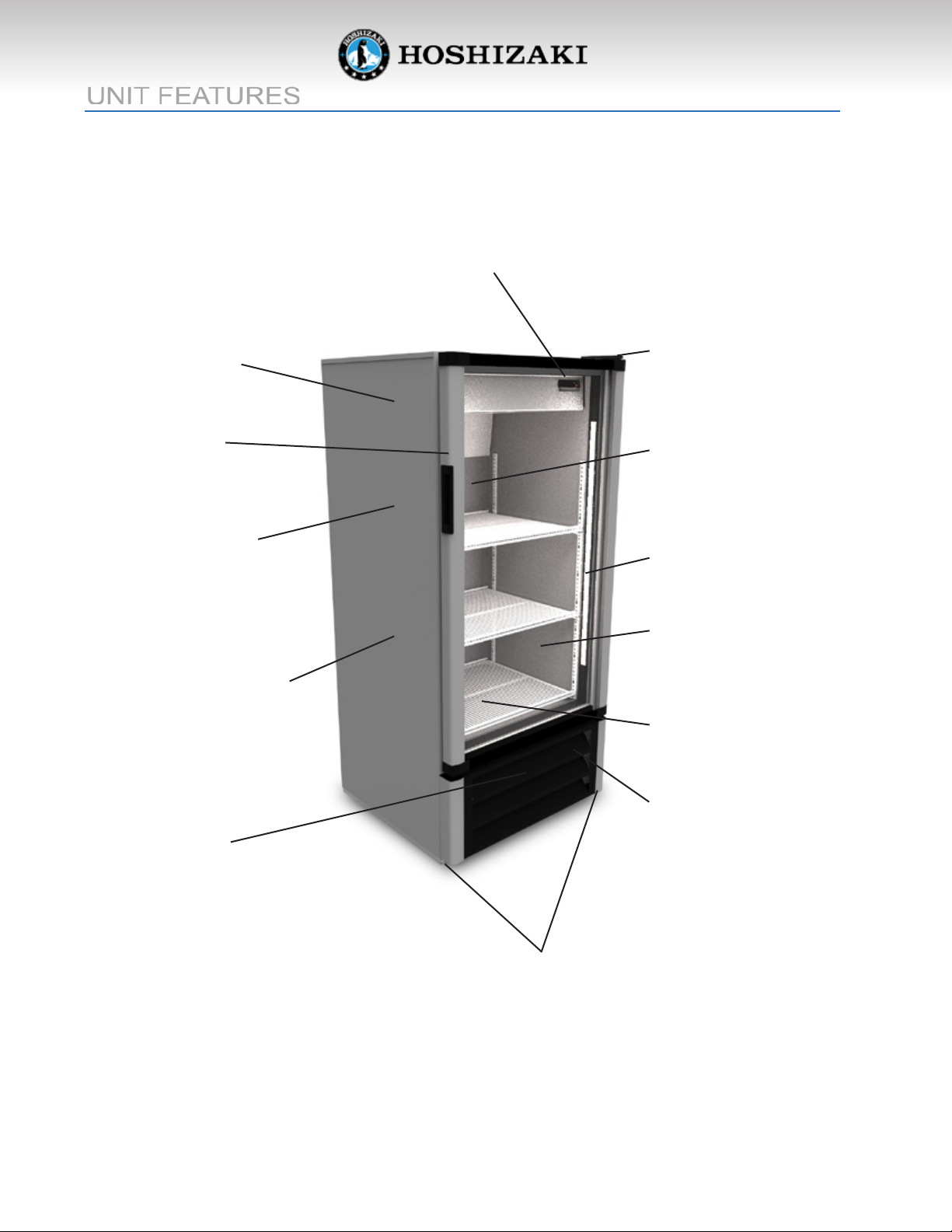
UNIT FEATURES
Energy saving electronic thermostat
with digital temperature reading
Forced-air evaporator for quick
temperature pull down
Durable PVC frame
Strong body with 1 3/4” thick
walls, injected with
polyurethane foam using
cyclopentane as the blowing
agent earth friendly
Exterior cabinet made of
galvanized, pre-painted steel,
with baked polyester paint
Heavy duty hinges
Double-pane Low-E glass
door for high ambient
condition
Interior lighting LED lamp strip
NSF compliant interior
cabinet
Reinforced heavy
duty shelves
Heavy duty R-134a
condensing unit with
easy access for
maintenance
4
Lint free
condenser
Reinforced, 16 gauge,
galvanized, steel base
RM-10
Page 5
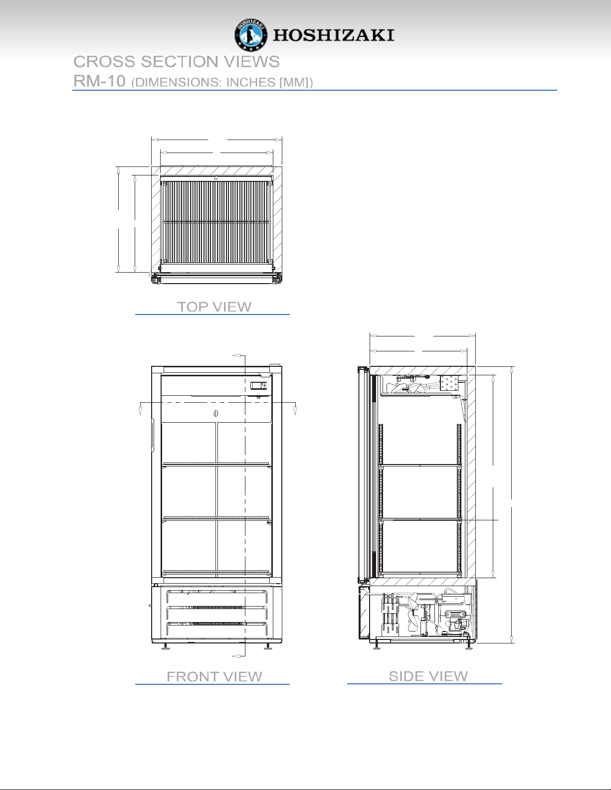
CROSS SECTION VIEWS
RM-10 (DIMENSIONS: INCHES [MM])
25 1/2
22
8
/
5
9
0
1
2
TOP VIEW
B
20 5/8
19
A
FRONT VIEW
A
6
1
/
9
9
3
4
5
B
SIDE VIEW
RM-10
5
Page 6
6
8
1
3
1
0
1
3
2
5
1
1
1
2
9
7
4
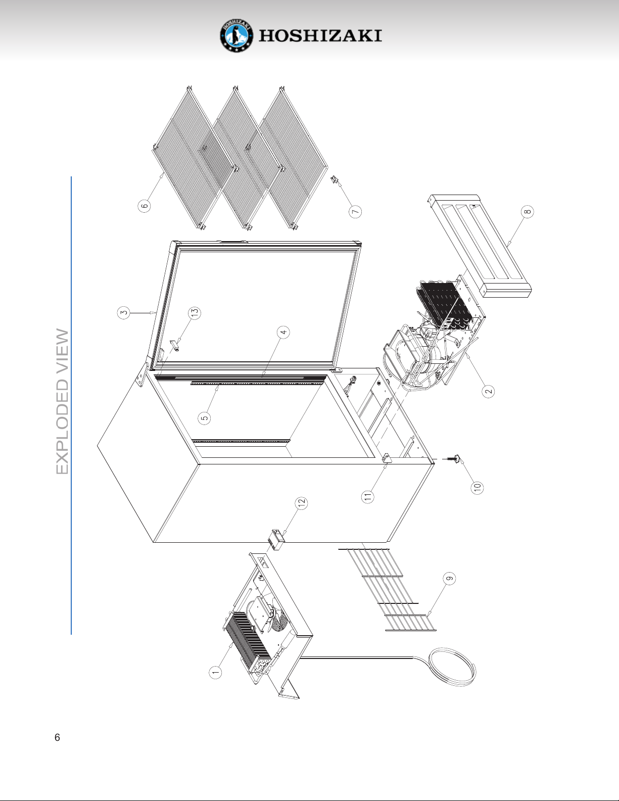
EXPLODED VIEW
6
RM-10
Page 7

EXPLODED VIEW
Quantity
Item No. Description Part No. per cooler
1 REFRIGERATION SYSTEM See pages 8 &9 1
2 COMPLETE 1/5HP 115V/60HZ CONDENSING UNIT EMY70HER-R 1
3 COMPLETE DOOR OT-PTA-RM10 1
4 INTERIOR LIGHTING SYSTEM See pages 14 & 15
5 PILASTER 30” PI-73 4
6 FLAT SHELF SH-0078-4-HD-FE 3
7 SHELF CLIPS CL-51-SS-E 12
8 FRONT GRILL EN-2334 1
9 BACK GRILL SH-0173-G-B 1
10 LEVELING LEGS LG-27 4
11 DOOR SUPPORT HA-200 1
12 ENERGY SAVING ELECTRONIC THERMOSTAT CT-185-CA 1
13 MAGNETIC SWITCH EL-360-C 1
RM-10
7
Page 8
REFRIGERATION SYSTEM
1
6
5
2
7
8
10
4
12
11
3
9
8
RM-10
Page 9

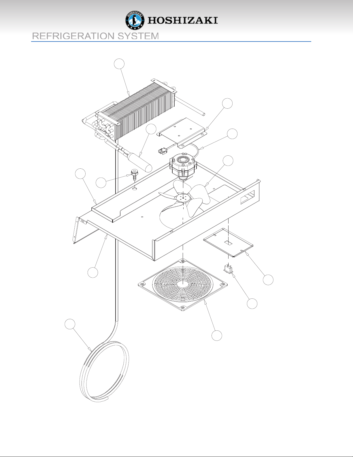
REFRIGERATION SYSTEM
Quantity
Item No. Description Part No. per cooler
1 EVAPORATOR CO-325 1
2 ACCUMULATOR DR-19-C 1
3 HEAT EXCHANGER TUB-0138 1
4 BAFFLE OT-19439 1
5 EVAPORATOR PAN OT-8776 1
6 EVAPORATOR FAN MOTOR BRACKET OT-8916 1
7 EVAPORATOR FAN MOTOR FA-41 1
8 EVAPORATOR FAN BLADE FA-2-EBM 1
9 FAN GUARD FA-62 1
10 PLASTIC DRAIN DR-1-P 1
11 LIGHT SWITCH EL-303-E 1
12 SWITCH BRACKET OT-9981 1
RM-10
9
Page 10

CONDENSING UNIT ASSEMBLY AND ITS COMPONENTS
3
8
5
2
1
7
10
1
2
11
6
9
4
10
RM-10
Page 11

CONDENSING UNIT ASSEMBLY AND ITS COMPONENTS
Quantity
Item No. Description Part No. per cooler
1 1/5HP 115V/60HZ COMPRESSOR EMY70HER 1
2 4TM762MFBZZ-53 OVERLOAD PROTECTOR EL-1989-R 1
3 21351500-7 RELAY EL-1990-R 1
4 ELECTRICAL BOX EL-1991-R 1
5 270-324 µF START CAPACITOR CAP-270-324-K 1
6 CONDENSER CO-452 1
7 CONDENSER FAN MOTOR FA-41 1
8 CONDENSER FAN BLADE FA-2-EBM 1
9 CONDENSER FAN MOTOR BRACKET FA-39 1
10 DRIER DR-31-C 1
11 COMPRESSOR EVAPORATION TRAY DP-4 1
12 POWER CORD EL-1265-9 1
RM-10
11
Page 12

SWING DOOR ASSEMBLY AND ITS COMPONENTS
3
6
2
5
7
12
1
RM-10
4
Page 13

SWING DOOR ASSEMBLY AND ITS COMPONENTS
Quantity
Item No. Description Part No. per cooler
1 GLASS PANE GL-675-AD-E 1
2 MAGNETIC GASKET TPE GA-313-B 1
3 UPPER HINGE ASSEMBLY HA-496-R 1
4 LOWER HINGE ASSEMBLY HA-535-R 1
5 TORSION MECHANISM HA-479 1
6 MAGNETIC SWITCH EL-360-D 1
7 DOOR HANDLE OT-HA-627 1
RM-10
13
Page 14

INTERIOR LIGHTING SYSTEM
1
2
3
14
RM-10
Page 15

INTERIOR LIGHTING SYSTEM
Quantity
Item No. Description Part No. per cooler
1 29 1/2” LED LAMP STRIP EL-147 2
2 4 7/8” LED PROFILE COVER OT-BR-253-57-4.875 4
3 1.25 Amp. LED POWER SUPPLY OT-EL-151-T 1
RM-10
15
Page 16

FRONT GRILL ASSEMBLY
3
9
2
1
5
9
7
4
8
6
3
16
RM-10
Page 17

FRONT GRILL ASSEMBLY
Quantity
Item No. Description Part No. per cooler
1 FRONT GRILL LEFT PROFILE PL-634-GREY-10.125 1
2 FRONT GRILL OT-19438 1
3 FRONT GRILL CORNER B PL-633-A 2
4 FRONT GRILL CORNER A PL-632-A 1
5 FRONT GRILL CORNER C PL-632-B 1
6 FRONT GRILL RIGHT PROFILE PL-634-GREY-10.125 1
7 FRONT GRILL REINFORCEMENT OT-18183 1
8 FRONT GRILL REINFORCEMENT OT-18002 3
9 FRONT GRILL REINFORCEMENT OT-19437 2
RM-10
17
Page 18

115 V./60 Hz./1 PHASE ELECTRICAL WIRING DIAGRAM
18
RM-10
Page 19

TROUBLESHOOTING
Possible causes and solutions
PROBLEM POSSIBLE CAUSE SOLUTION
COMPRESSOR NO VOLTAGE IN THE ELECTRICAL USE A VOLTMETER TO
WILL NOT START SOCKET CHECK THE VOLTAGE
THE ELECTRICAL CONDUCTOR USE AN OHMMETER,
OR WIRES MAY BE CUT TO CHECK FOR CONTINUITY
DEFECTIVE ELECTRICAL REPLACE DEFECTIVE
COMPONENTS SUCH AS: COMPONENTS
THERMOSTAT, RELAY, THERMAL
PROTECTOR, ETC.
COMPRESSOR MOTOR HAS A MEASURE THE OHMIC
WINDING OPEN OR SHORTED RESISTANCE OF THE MAIN AND
AUXILIARY WINDINGS USING AN
OHMMETER. COMPARE THEM WITH
THE CORRECT VALUES
DIRTY CONDENSER, LACK OF AIR CLEAN CONDENSER AND
FLOW ALLOW FOR AIR CIRCULATION
LOW VOLTAGE USE A VOLTAGE REGULATOR IF
THE VOLTAGE IS LOWER THAN
100 VOLTS
COMPRESSOR IS STUCK CHANGE THE COMPRESSOR
THE TEMPERATURE THERMOSTAT DOES NOT DISCONNECT CHECK THE INSTALLATION OF THE
IS TOO COLD THE CONDENSING UNIT THERMOSTAT. IF THE PROBLEM
PERSISTS, CHANGE THE THERMOSTAT
THERMOSTAT’S AMBIENT SENSOR IS CORRECTLY FASTEN THE
LOOSE OR INSTALLED IMPROPERLY THERMOSTAT’S AMBIENT SENSOR
THE TEMPERATURE CONDENSER IS DIRTY; LACK OF AIR CLEAN THE CONDENSER AND
IS NOT COLD ENOUGH FLOW ALLOW FOR AIR CIRCULATION
RM-10
19
Page 20

PROBLEM POSSIBLE CAUSE SOLUTION
THE TEMPERATURE THE REFRIGERATOR HAS BEEN THE UNIT MUST NOT BE NEAR
IS NOT COLD ENOUGH PLACED AT AN INADEQUATE STOVES, WALLS THAT ARE
LOCATION EXPOSED TO THE SUN, OR PLACES
THAT LACK SUFFICIENT AIR FLOW
THE REFRIGERATOR HAS BEEN USED THE SHELVES MUST NEVER BE
IMPROPERLY COVERED WITH ANY TYPE OF PLASTIC OR
OTHER MATERIAL THAT WILL BLOCK THE
CIRCULATION OF COLD AIR WITHIN THE
REFRIGERATOR
THE REFRIGERATOR HAS BEEN CHECK TO SEE IF CONDENSATION
OVERCHARGED WITH THE OR ICE CRYSTALS HAVE FORMED
REFRIGERANT GAS ON THE SUCTION LINE. IF SO, CHARGE
WITH THE CORRECT AMOUNT OF GAS
THE REFRIGERANT GAS IS LEAKING FIND THE LOCATION WHERE THE GAS IS
LEAKING IN ORDER TO SEAL IT OR
REPLACE THE DEFECTIVE COMPONENT.
CHANGE THE DRIER. PERFORM A GOOD
VACUUM AND RECHARGE THE UNIT
THE EVAPORATOR AND/OR CHECK THE ELECTRICAL CONNECTIONS
CONDENSER FANS AREN’T WORKING AND MAKE SURE THAT THE FAN BLADE
ISN’T STUCK. REPLACE THE FAN MOTOR
IF IT DOESN’T WORK
LOW VOLTAGE USE A VOLTAGE REGULATOR IF THE
VOLTAGE IS LOWER THAN 100 VOLTS
ELECTRICAL SHOCKS WIRES OR ELECTRICAL COMPONENTS CHECK FOR APPROPRIATE INSULATION ON
ARE IN DIRECT CONTACT WITH THE CONNECTIONS OF EACH ELECTRICAL
METALLIC PARTS COMPONENT
NOISE THE REFRIGERATOR IS NOT CHECK IF THE NOISE GOES
PROPERLY LEVELED AWAY AFTER YOU LEVEL THE
REFRIGERATOR
THE CONDENSER IS NOT FASTENED WHILE THE COMPRESSOR IS WORKING,
CORRECTLY. COPPER TUBINGS CHECK TO SEE IF METAL PARTS ARE IN
ARE IN CONTACT WITH METAL CONTACT WITH ONE ANOTHER AND/OR
IF THE SCREWS THAT FASTEN THE
CONDENSER ARE TIGHTENED
THE EVAPORATOR AND/OR CHECK IF THE FANS ARE SECURELY
CONDENSER FANS ARE LOOSE FASTENED. ALSO, CHECK IF THE
FAN BLADES ARE LOOSE, BROKEN
OR CROOKED. IF SO, CHANGE THE
FAULTY BLADE
COMPRESSOR HAS AN INTERNAL IF THE NOISE PERSISTS AFTER
NOISE ALL OTHER MEASURES HAVE BEEN
TAKEN, IT MAY BE ORIGINATING FROM
THE COMPRESSOR
20
RM-10
Page 21

PROBLEM POSSIBLE CAUSE SOLUTION
EXTREME CONDENSATION THERMOSTAT’S AMBIENT SENSOR IS CORRECTLY FASTEN THE
INSIDE THE REFRIGERATOR LOOSE OR INSTALLED IMPROPERLY THERMOSTAT’S AMBIENT SENSOR
THE OUTSIDE ENVIRONMENT’S THIS TYPE OF OCCURRENCE IS
RELATIVE HUMIDITY IS VERY HIGH CAUSED BY LOCAL CLIMATIC
(OVER 75%) CONDITIONS AND NOT BY THE
REFRIGERATED UNIT
THE REFRIGERATOR DOOR WON’T CHECK THE DOOR AND/OR THE
SHUT COMPLETELY MAGNETIC GASKET. ADJUST THE
DOOR HINGES IF NEEDED; REPLACE
THE GASKET IF BROKEN
THE REFRIGERATOR HAS BEEN THE UNIT MUST NOT BE NEAR
PLACED AT AN INADEQUATE SOURCES THAT PRODUCE
LOCATION TOO MUCH HEAT
NO ILLUMINATION THE LIGHT SWITCH IS IN “OFF” PRESS THE LIGHT SWITCH
POSITION TO THE “ON” POSITION
FALSE CONTACT ON THE LIGHT INSPECT ALL CONNECTIONS
SWITCH OR LED
LIGHT SWITCH OR LED ARE DAMAGED REPLACE THE DAMAGED COMPONENT
THE THERMOSTAT IS SET TO OPERATE SET THE THERMOSTAT IN NORMAL
IN ENERGY SAVING MODE OPERATION MODE
RM-10
21
Page 22

REFRIGERATION SYSTEM
Component Description
COMPRESSOR:
The compressor is a factory sealed unit located
underneath (outside) the cooling cabinet. This
pump is activated by a motor which draws low
pressure vapor (refrigerant) from the evaporator.
It then compresses the gas and forces it into the
condenser at a high pressure.
situation, if the compressor overheats or if the
voltage source varies drastically, the thermal
protector opens, turning o the compressor. After
the compressor cools down to a normal and safe
working temperature, the thermal protector turns
on the compressor.
STARTER RELAY:
The starter relay is attached on one side of the
compressor box. The compressor motor has two
windings: one for starting and another for running.
In order to provide for the necessary additional
torque when the motor is rst ignited, the starter
relay connects the additional start-up windings. After the motor reaches its correct operating speed,
the relay opens the ignition windings and the motor
carries on with the operation windings.
THERMAL PROTECTOR:
This protector is a thermo-sensible device attached
to one side of the compressor’s box. In any given
EVAPORATOR CONDENSER
CAPILLARY
CONDENSER:
The condenser is located underneath (outside)
the cooling cabinet in front of the compressor. Its
receives hot, high pressure refrigerant gas from
the compressor, and cools it down until it returns
to liquid state.
CONDENSER FAN MOTOR:
The condenser fan motor is located underneath
the cooling cabinet. It is a ventilation device which
forces the ambient air to ow over the condenser in
order to cool down the refrigerant owing inside it.
The fan motor works only if the compressor is on.
DRIER
22
EVAPORATOR
FAN MOTOR
ACCUMULATOR
SUCTION
COMPRESSOR
RM-10
DISCHARGE
LEGEND
CONDENSER
FAN MOTOR
GAS
FLOW
Page 23

REFRIGERATION SYSTEM
Component Description
EVAPORATOR:
The evaporator is located inside the cooling
cabinet. As the gas ows at a low pressure through
the evaporator, it absorbs serpentine and removes
the heat from inside the cabinet.
EVAPORATOR FAN MOTOR:
This device produces the required circulation of
air through the cooling cabinet as well as over the
surface of the evaporator’s serpentine thermal
exchange area. This fan motor runs continuously.
The evaporator and condenser serpentines have
aluminum ns that help increase the surfaces for
the thermal exchange in an ecient way.
CAPILLARY TUBE:
It consist of several feet of tubing having a small
inside diameter. It is a device used to control
the amount od refrigerant that flows into the
evaporator.
DRIER:
The drier is located in between the condenser and
the evaporator. It traps and removes moisture
in the refrigeration system while allowing oil and
refrigerant to ow freely.
ENERGY SAVING ELECTRONIC
THERMOSTAT:
The electronic thermostat is responsable for
detecting temperature changes inside the cabinet.
It starts the compressor whenever the cabinet
temperature rises above the desired temperature.
The compressor recirculates the refrigerant
throughout the system, lowering the temperature
inside the cooling compartment. When the
temperature drops to the set point programmed
in the thermostat, it turns o the compressor and
a new cycle starts again.
This electronic thermostat contains a dispositive
to save energy when the sales of the day are
over. This dispositive is activated by pressing the
“Energy Saving” button of the thermostat. When
this button is pressed, the lights are turned o
and the refrigerator starts operating in a warmer
temperature setting, consuming less energy.
COOLING CABINET:
This is the area where the goods are stored. It
has been designed to allow for constant cold air
circulation to ow through the goods.
ACCUMULATOR:
The accumulator is located in between the
evaporator and the compressor. It is a storage
tank which receives refrigerant liquid from the
evaporator and prevents it from owing into the
compressor.
RM-10
23
Page 24

THE REFRIGERATION CYCLE
1. As the temperature inside the cooling compartment increases, it is detected by the thermostats’
sensor. The thermostat then turns the compressor and the condenser motor on once the
programmed temperature is reached.
2. The compressor recirculates the refrigerant throughout the system by drawing the refrigerant gas
at a low vapor pressure from the evaporator. Then it compresses the refrigerant and forces it
into the condenser.
3. The condenser, with the help of its fan motor, removes the refrigerants’ heat as its ows through
the condenser. The heat is then released to the outside environment. Consequently, the decrease
in temperature will change the refrigerant from a gaseous to a liquid state.
4. The capillary tube regulates the amount of refrigerant that is discharged into the evaporator and
expands it. This expansion causes the refrigerant temperature to decrease.
5. The evaporators' serpentine allows the refrigerant to absorb and remove heat from the cooling
compartment.
6. The drop in temperature inside the cooling compartment is caused by the refrigerant’s continuous
circulation through the system. This gas continuously absorbs the heat that exists inside the
cooling compartment and expels it to the outside environment. When the temperature drops to
its programmed set point, it is detected by the thermostat and it turns o the compressor and
condenser motor.
24
RM-10
Page 25

1Axxxx-010
 Loading...