

Hoshizaki RH2-SSB-GD Parts List

September 27, 2005
PARTS LIST
ISSUED:
May 22, 2000
REACH-IN
Reliability is a
beautiful thing
TM
REVISED:
TempGuard
Model
ITEM #:
71170
RH2-SSB-GD

CONTENTS
Auxiliary Codes ...................................................................................................................... 3
Note About Ordering Parts .................................................................................................... 3
Material Abbreviations ........................................................................................................... 4
A. Reach-In ............................................................................................................................ 5
B. Refrigeration Assembly ..................................................................................................... 7
C. Control Panel Assembly .................................................................................................. 11
D. Body-Final ....................................................................................................................... 13
E. Label Location ................................................................................................................. 15
F. Condenser Assembly ....................................................................................................... 16
G. Evaporator Assembly ...................................................................................................... 18
H. Evaporator Shroud Assembly .......................................................................................... 19
J. Evap Drain Pan Assembly ................................................................................................ 20
K. Control Box Assembly ..................................................................................................... 21
L. Body-Prefinal ................................................................................................................... 23
M. Mullion-Vertical ............................................................................................................... 25
N. Panel-Front Hinged Assembly ......................................................................................... 27
P. Literature and Packaging ................................................................................................. 28
2

Auxiliary Codes
RH2-SSB-GD K-0 May 2000
L-5 March 2001
M-5 May 2002
N-6 January 2003
P-5 December 2003
Q-5 December 2004
Note About Ordering Parts
Most assemblies cannot be ordered as complete units; parts in the assemblies generally must
be ordered separately.
3

Material Abbreviations
ALUMINUM
AL = Aluminum
COPPER
CU = Copper
PLASTIC
ABS = Acrylonitrile -butadiene - styrene
AC = Polyacetal
EVA = Ethylene vinyl acetate
PA = Polyamide = Nylon
PC = Polycarbonate
PE = Polyethylene
PES = Polyester
PETP = Polyethylene terephthalate = Tetlon
PP = Polypropylene
PS = Polystyrene
PTFE = Polytetrafluoroethylene = Teflon
PUR = Polyurethane
PVC = Polyvinyl chloride
RUBBER
VN = Vinyl Nitrile
EPDM = EP rubber
NBR = Nitrile butadiene rubber
NR = Natural rubber
NP = Neoprene
SI.R = Silicone rubber
SY.R = Synthetic rubber
EPH = Epichlorohydrin
STEEL
GS = Galvanized steel
SS = Stainless steel
PS = Plated steel
PAS = Primed steel
AUXILIARY CODE
L-5
Designates the year. "L" indicates the year 2001. Years progress or regress in alphabetical order.
"J" is 1999, "K" is 2000, "M" is 2002, and so on. The letters "I" and "O" were skipped.
Designates significant part changes within the same year for this model. Base is 5 (0 for code
K-0) and this number advances for each change.
Example: P-6
"P" indicates 2004.
"6" indicates the first significant part change for 2004.
4
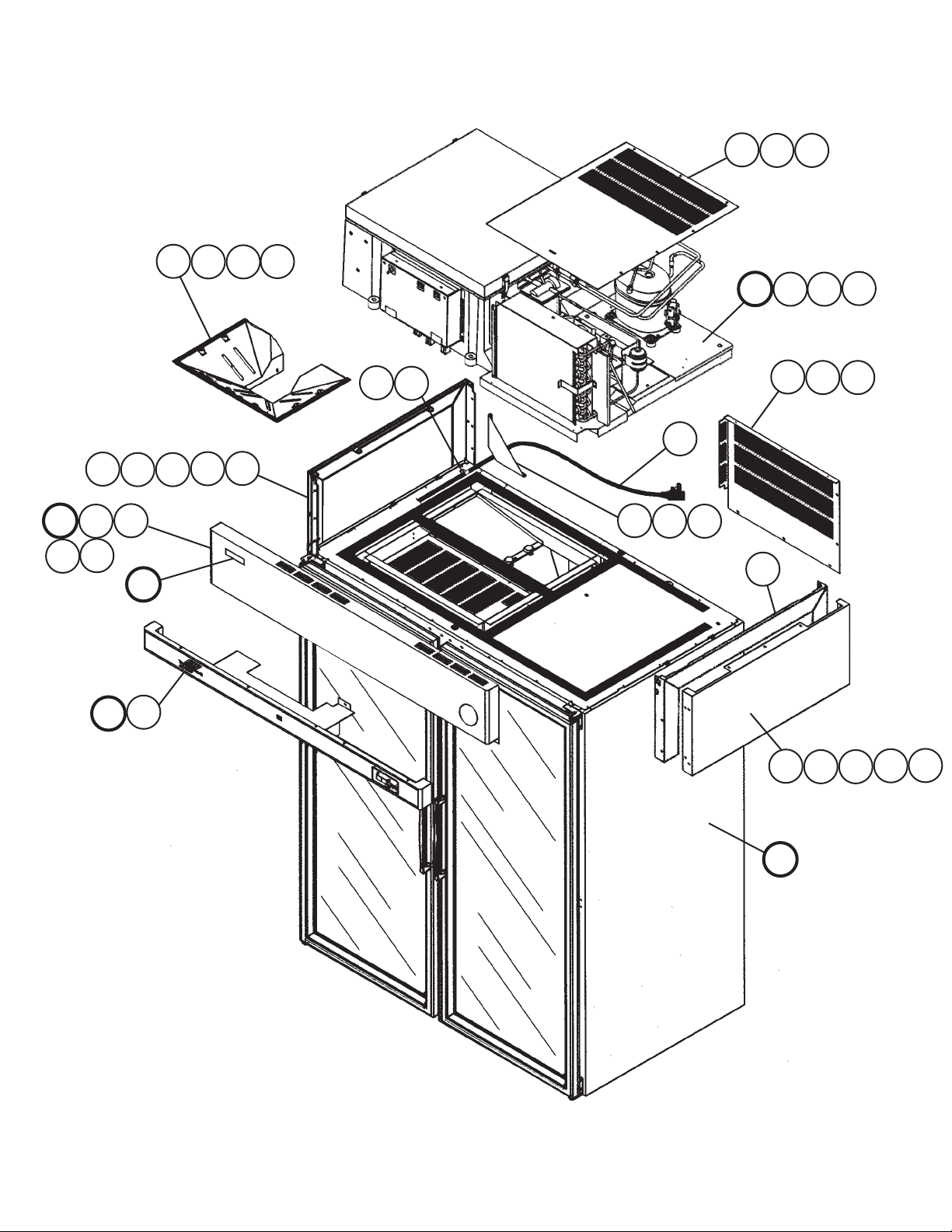
A. Reach-In
RH2-SSB-GD
K-0, L-5, M-5, N-6, P-5, Q-5
4a44b
N
N3
N1
3
2a22b
N2
E
8a88b
2d
2c
9
B1 B2
B
6a
6
7
1a11b
10
B3
5a55b
C
C1
2d
2a22b
2c
D
5
Title: A. Reach-In Model: RH2-SSB-GD
Index
No
. Description
B Refr
igeration Assembly - 1A0493A01 1 1 1 1
B1 Bolt Assemb
B2 He
B3 W
x Bolt 8×70 7B01-0870 2 2 2 2
asher 8, SS 7W22-0800 2 2 2 2
C Control P
C1 T2 Scre
w 4×8, SS 7P32-0408 7 7 7 7
ly 8×45 437889-01 6 6 6 6
anel Assembly - 2A1219A03 1 1 1 1
Material or
Model Number Part Number
K-0
L-5
M-5
N-6
P-5 Q-5
D Body – Final - 2A1215A03 1 1 1 1
E Label Location - 3A0603G05 1 1 1 1
anel – Front Hinged Assembly - 2A2011A02
N P
N1 Cle
vis Pin 8907-0102 2 2 2
See
Part #3
Below
1 1 1
N2 Clotter Pin 8907-0103 2 2 2
N3 Flat
Washer 4A0655-03 2 2 2
Required Number
1 Gusset – Side
, Top GS 3A1006-01 1 1 -
Gusset – Frame 4A2845-01 1 -
4A3856-01 1
1a T2 Scre
1b T
2 P
w 4×8, SS 7P32-0408 2 2 4 4
russ Head Screw 5×10 7C31-0510 2 2 -
anel – Side, Top SS 2A0615-02 2 -
2A1800-01 2 2 2
2a Inser
2b T
2c Countersunk Scre
2d Br
3 P
4 T
4a T2 Scre
4b T
5 Rear UL Co
5a T2 Scre
5b T
t – Threaded M5 4A0407-01 10 4 4 4
aper Collar SS 4H0171-01 4 4 4 4
w 5×20, SS 7C42-0520 4 4 4 4
acket – Hinge GS 4A2306-01 2 2 2
anel – Front SS 1A0040-01 1 See Assembly N
op UL Cover GS 2A1118-03 1 1 1 1
w 4×8, SS 7P32-0408 2 5 5 5
russ Head Screw 5×10, SS 7C32-0510 3 -
ver GS 2A1117-01 1 1 1 1
w 4×8, SS 7P32-0408 3 5 5 5
russ Head Screw 5×10, SS 7C32-0510 2 -
6 Wire Clamp PS 4A0809-03 1 1 1 1
russ Head Screw 5×8, SS 7C32-0508 1 1 1 1
6a T
ower Cordset - 4A1543-01 1 1 1 1
7 P
8 Distr
8a T2 Scre
8b T2 Scre
9 Gask
10 F
ibutor – Air Top ABS 1A0152-02 1 1 1 1
w 4×8, SS 7P32-0408 7 7 7 7
w 4×10, SS 7P32-0410 2 2 2 2
et L=1061 4A0808L02 1 1 1 1
rame – Side Top GS 2A1803-01 2 2 2
6
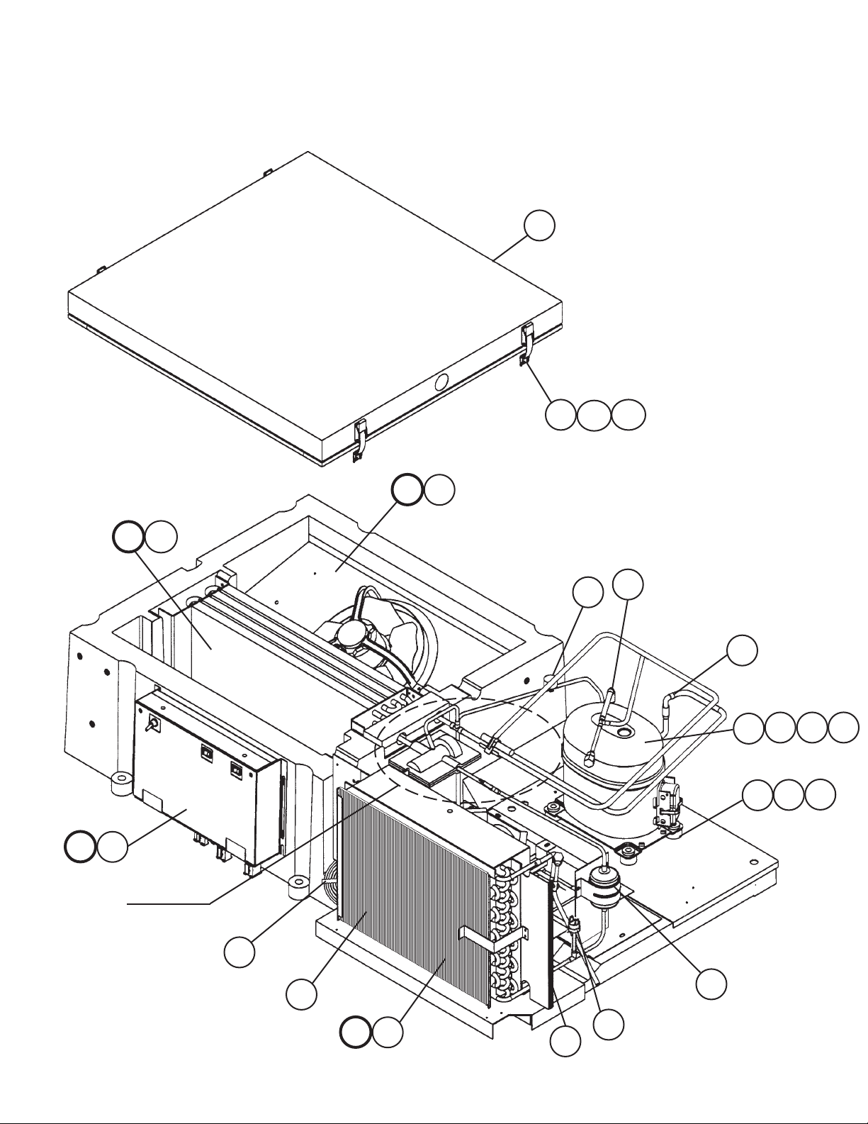
B. Refrigeration Assembly
1/2
RH2-SSB-GD
K-0, L-5, M-5, N-6, P-5, Q-5
5
29b
29a
29
K
G1
G
K1
Detail A
See Next Page
Refrigeration 2/2
H
H1
15
25
25
1
2
1a 1b
3
1c
4
27
16
F
F1
17
30
28
7
B. Refrigeration Assembly
2/2
RH2-SSB-GD
K-0, L-5, M-5, N-6, P-5, Q-5
7
2120
Detail A
9
10
10a
11
23
26
24
22
8
19
6
19a
18
18a
J
J1
31
12
13
14
8

Title: B. Refrigeration Assembly Model: RH2-SSB-GD
Index
No
. Description
F Condenser Assemb
F1 T2 Scre
G Ev
G1 T2 Scre
H Ev
H1 T
J Ev
w 4×8, SS 7P32-0408 4 4 4
ap Assembly - 2A1297A02 1 1 1
w 4×8, SS 7P32-0408 2 2 2
ap Shroud Assembly - 3A0263G01 1 1 1
russ Head Screw 4×16, SS 7C32-0416 2 2 2
ap Drain Pan Assembly - 4A0679A02 1 -
ly - 3A0585A01 1 1 1
Material or
Model Number Part Number
K-0 L-5
4A0679A03 1 1
J1 T2 Scre
K Control Bo
K1 T
w 4×8, SS 7P32-0408 6 6 6
x Assembly - 2A1732A01 1 1 1
russ Head Screw 4×16, SS 7C32-0416 4 4 4
1 Compressor - 4A1820-01 1 1 1
1a Protector
1b Protectiv
e Cover Group AKP1000
(Included with new
compressor)
1c Protector Holder 26126 1 1 1
4A1875-01 1 1 1
Supplied with
compressor
1 1 1
2 Spacer 027-0072-02 434404-01 4 4 4
3 Grommet 027-0073-00 434403-01 4 4 4
4 Bolt - 437889-01 4 4 4
5 Co
6 Cond – Dis Assemb
7 Expansion
8 Pipe – Ev
9 Ther
10 Ther
10a T
11 Ther
12 Elbo
ver Evap Case - 2A0245G01 1 1 1
ly - 3A1585G01 1 1 1
Valve 4A2095-01 1 1 1
ap Drain PVC 3A0143-01 1 1 1
mistor – Cabinet 4A1429 4A1429-01 1 1 1
mistor Bracket (A) ABS 433964-01 1 1 1
russ Head Screw 4×16, SS 7C32-0416 2 2 2
mistor Bracket (B) SS 433920-01 1 1 1
w – Tubing PP 4A0711-01 1 1 1
13 Bushing SB-750-625 420470-13 1 1 1
14 Vin
15 Ther
yl Hose L=350 7730I3812 1 1 1
mostat – Clean Filter 37TJ32 4A0484-01 1 1 1
16 Filter – Condenser - 3A0277-02 1 1 1
17 Dr
18 Dr
18a T2 Scre
19 Dr
19a T2 Scre
20 Exp
21 Exp
22 Holder – Exp
23 Seal – Ref
ier C-05E73 4A0924-01 1 1 1
ier Stand GS 4A0949-01 1 1 1
w 4×8, SS 7P32-0408 2 2 2
ier – Bracket GS 4A0806-01 1 1 1
w 4×8, SS 7P32-0408 2 2 2
Valve Cover (A) PE Foam 3A0372-01 1 1 1
Valve Cover (B) PE Foam 3A1495-01 1 1 1
Valve SS 3A0107-01 1 1 1
Tubing NP 3A0257-01 2 2 2
24 Hose Clamp 6808 443461-01 1 1 1
Required Number
M-5
to
Q-5
9
 Loading...