

Hoshizaki RH1-AAC-W Parts Manual

August 9, 2005
PARTS LIST
ISSUED:
October 16, 2003
REACH-IN
Reliability is a
beautiful thing
TM
REVISED:
SafeTemp
Model
ITEM #:
71226
RH1-AAC-W
1

CONTENTS
Auxiliary Codes ...................................................................................................................... 3
Note About Ordering Parts .................................................................................................... 3
Material Abbreviations ........................................................................................................... 4
A. Reach-In ............................................................................................................................ 5
B. Refrigeration System ......................................................................................................... 7
C. Panel-Front Hinged Assembly ......................................................................................... 10
D. Body-Final ....................................................................................................................... 11
E. Control Box Assembly ..................................................................................................... 13
F. Label Location .................................................................................................................. 15
G. Fan-Evaporator Assembly ............................................................................................... 16
H. Evaporator Assembly ...................................................................................................... 17
J. Condenser Assembly ....................................................................................................... 18
K. Body-Prefinal ................................................................................................................... 20
L. Door-Left .......................................................................................................................... 22
M. Literature & Packaging .................................................................................................... 24
2

Auxiliary Codes
RH1-AAC-W M-5 November 2002
N-5 December 2002
N-6 January 2003
P-5 December 2003
P-6 October 2004
P-7 November 2004
Q-5 December 2004
Q-6 June 2005
Note About Ordering Parts
Most assemblies cannot be ordered as complete units; parts in the assemblies generally must
be ordered separately.
3

Material Abbreviations
ALUMINUM
AL = Aluminum
COPPER
CU = Copper
PLASTIC
ABS = Acrylonitrile -butadiene - styrene
AC = Polyacetal
EVA = Ethylene vinyl acetate
PA = Polyamide = Nylon
PC = Polycarbonate
PE = Polyethylene
PES = Polyester
PETP = Polyethylene terephthalate = Tetlon
PP = Polypropylene
PS = Polystyrene
PTFE = Polytetrafluoroethylene = Teflon
PUR = Polyurethane
PVC = Polyvinyl chloride
RUBBER
VN = Vinyl Nitrile
EPDM = EP rubber
NBR = Nitrile butadiene rubber
NR = Natural rubber
NP = Neoprene
SI.R = Silicone rubber
SY.R = Synthetic rubber
EPH = Epichlorohydrin
STEEL
GS = Galvanized steel
SS = Stainless steel
PS = Plated steel
PAS = Primed steel
AUXILIARY CODE
K-5
Designates the year. "K" indicates the year 2000. Years progress or regress in alphabetical order.
"J" is 1999, "L" is 2001, "M" is 2002, and so on. The letters "I" and "O" were skipped.
Designates significant part changes within the same year for this model. Base is 5 and this number
advances for each change.
Example: P-6
"P" indicates 2004.
"6" indicates the first significant part change for 2004.
4
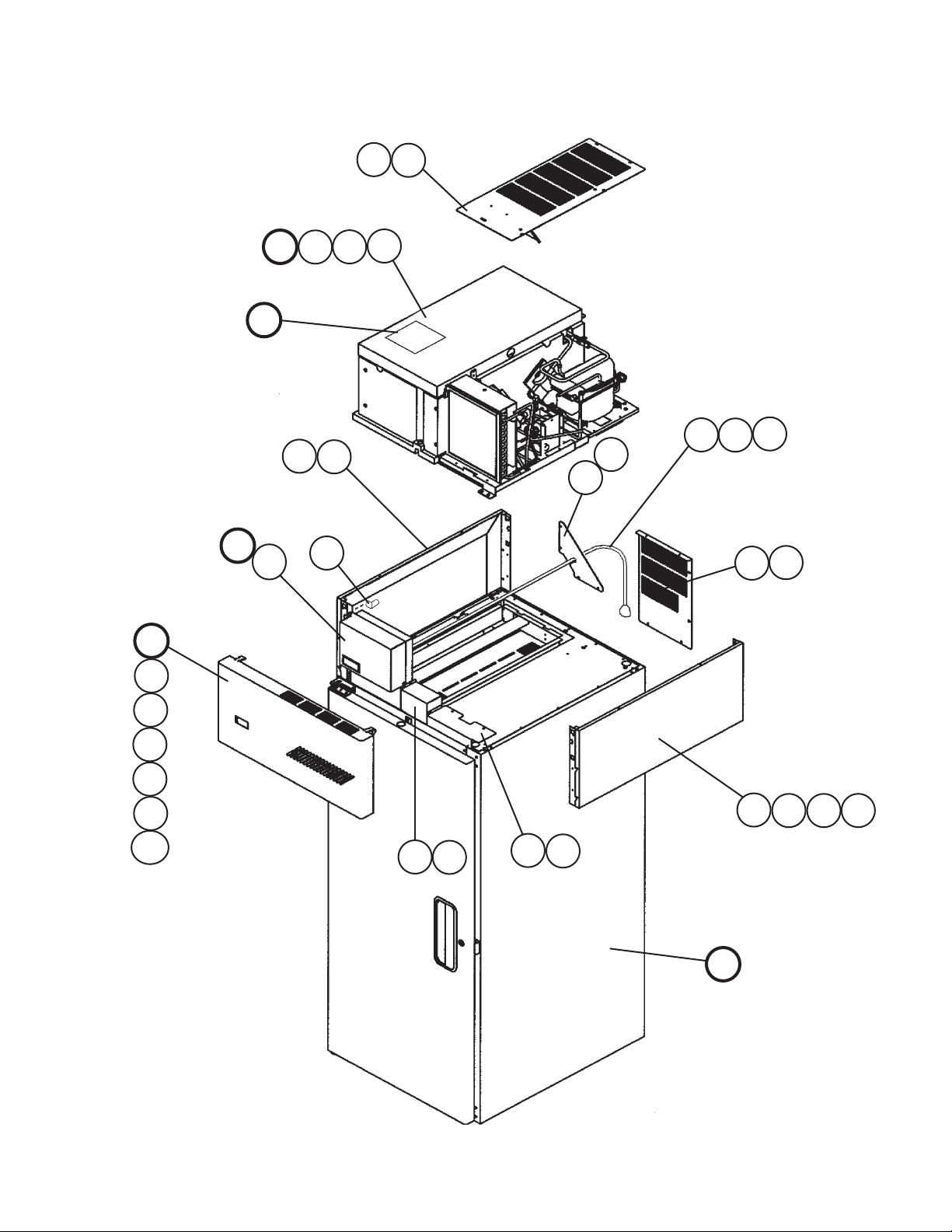
A. Reach-In
RH1-AAC-W
M-5, N-5, N-6, P-5, P-6, P-7, Q-5, Q-6
4
B3
B2
B1
B
F
4a
C
C1
C2
C3
C4
10
10a
E
E1
6
2a
2
11
9a
8a
8
9
1a
1
12
7
5a
5
3a33b
3c
D
5
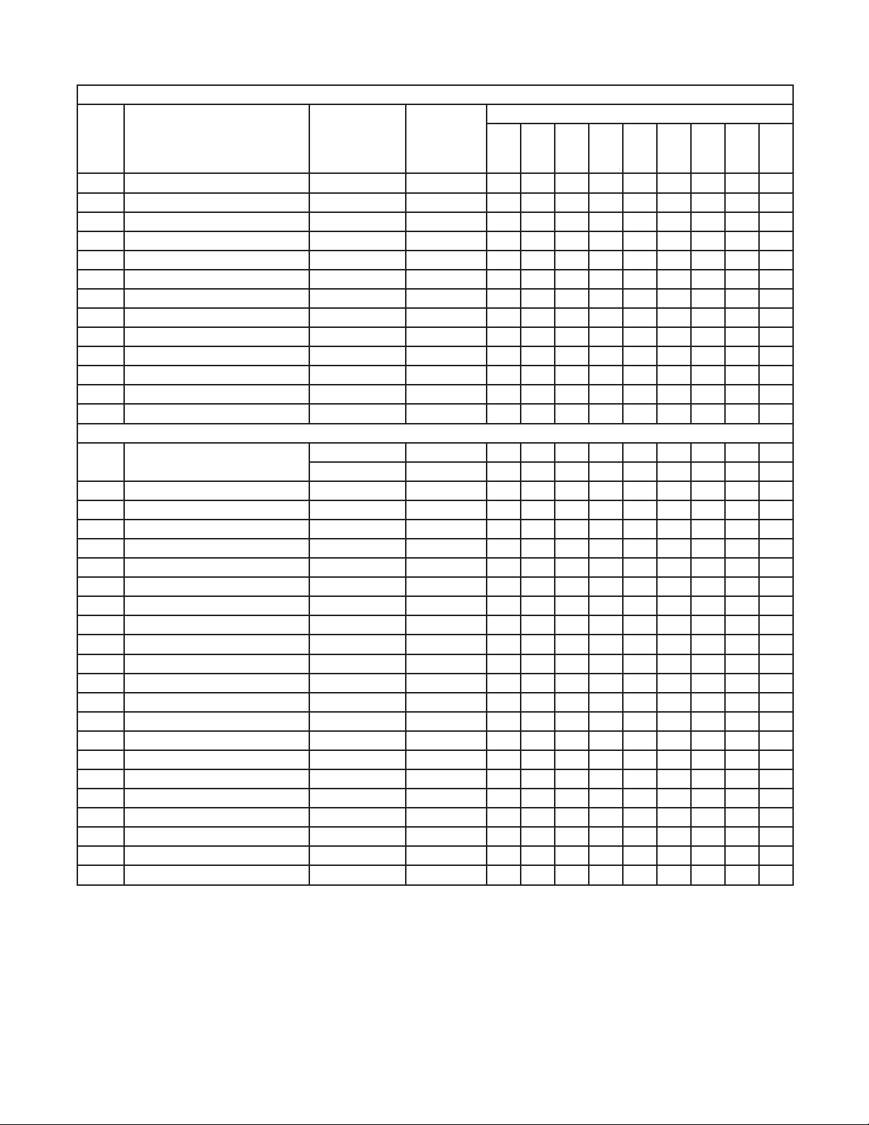
Title: A. Reach-In Model: RH1-AAC-W
M-5
Index
No
. Description
B Refr
B1 Bolt Assemb
B2 T
B3 W
C P
C1 Cle
C2 Cotter Pin - 8907-0103 2 2
C3 Flat
C4 Spacer – Hinge - 4A2473-01 2 2
D Body – Final - 1A0299A07 1 1
E Control Bo
E1 T2 Scre
F Label Location - 2A1042A12 1 1
igeration System
ly 8×45 437889-01 5 5
russ Head Screw 5×25, SS 7C32-0525 2 2
asher 5 7W22-0500 2 2
anel – Front Hinged Assembly - 3A1670A01 1 1
vis Pin - 8907-0102 2 2
Washer - 4A0655-03 2 2
x Assembly - 2A1842A01 1 1
w 4×8, SS 7P32-0408 3 3
Material or
Model Number Part Number
Refrigerator
1A0297A02 1 1
to
Q-5 Q-6
Required Number
1 Gusset – F
1a T2 Scre
rame – Side Top GS 2A1803-01 2 2
2 F
russ Head Screw 5×10, SS 7C32-0510 8 8
2a T
anel – Side, Top SS 2A1800-21 2 2
3 P
russ Head Screw 5×10, SS 7C32-0510 2 2
3a T
aper Collar SS 4H0171-01 2 2
3b T
3c Scre
4 UL – Co
4a T2 Scre
5 Co
5a T2 Scre
6 P
7 Wire Clamp - 4A0809-02 1 1
8 Co
8a T2 Scre
9 Co
9a T2 Scre
10 Br
10a T2 Scre
11 Br
12 Bushing - 420470-01 1 1
ver – UL, Rear GS 2A2752-01 1 1
ower Cord - 4A0520-01 1 1
ver – Connector Wire GS 3A1678-01 1 1
ver – Wire GS 3A1679-01 1 1
acket – Hinge GS 4A2306-01 2 2
acket – Control Box - 4A2467-01 1 1
rame GS 4A2845-01 1 -
4A3856-01 1
w 4×8, SS 7P32-0408 4 4
w Countersunk 5×20, SS 7C42-0520 2 2
ver Assembly Top - 2A2757G02 1 1
w 4×8, SS 7P32-0408 5 5
w 4×8, SS 7P32-0408 4 4
w 4×8, SS 7P32-0408 2 2
w 4×8, SS 7P32-0408 3 3
w 4×8, SS 7P32-0408 3 3
6
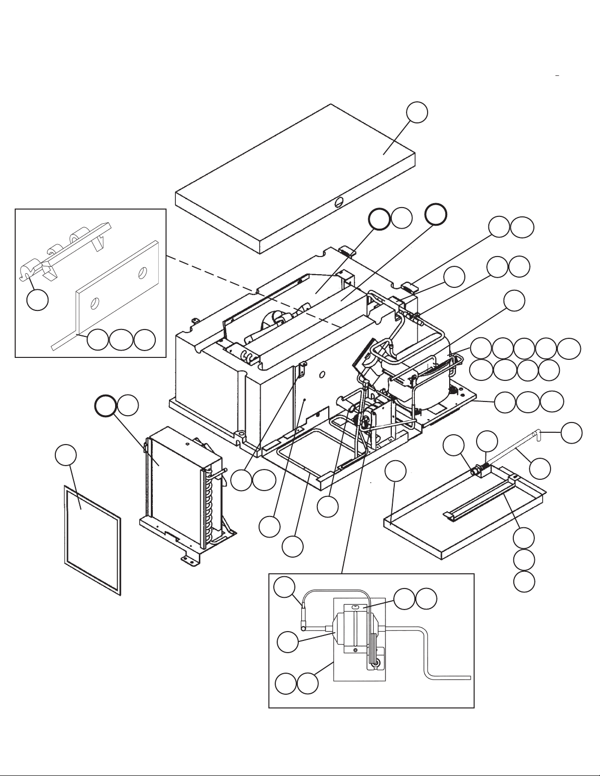
B. Refrigeration System
RH1-AAC-W
M-5, N-5, N-6, P-5, P-6, P-7, Q-5, Q-6
8
17
22
18
J
18a
J1
19
31
31a
G
G1
6
H
24
5
29
20
11
12
14b 14c
23
3
29a
21
9
13
23a
27
15
14
28
23b
14a
26
30
25
1
9
10
16
4
7
7a
2a
2
9a
7
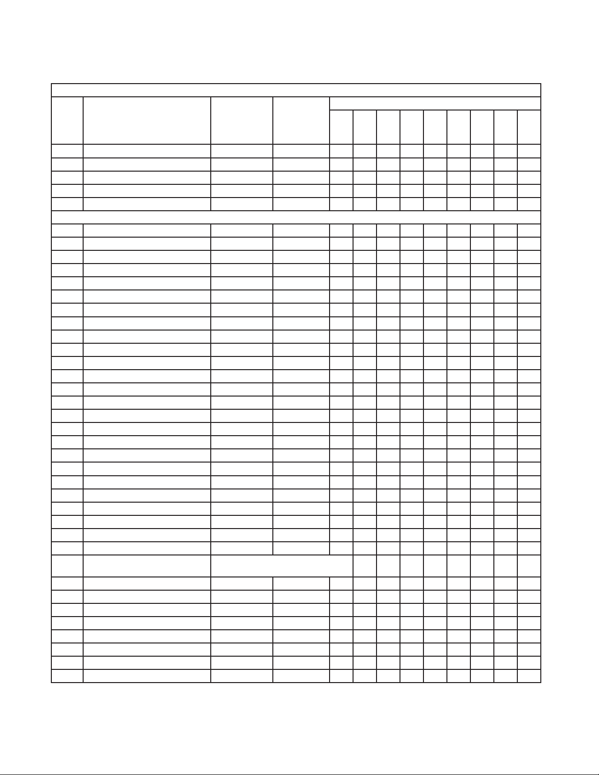
Title: B. Refrigeration System Model: RH1-AAC-W
Index
No
. Description
an – Evaporator Assembly - 2A0980A01 1
G F
G1 T
russ Head Screw 4×12, SS 7C32-0412 4
H Ev
J Condenser Assemb
J1 T2 Scre
aporator Assembly - 2A1263A02 1
w 4×8, SS 7P32-0408 2
ly - 3A2609A01 1
Material or
Model Number Part Number
Required Number
M-5
to
Q-6
1 Dr
2 Mount – Dr
2a T2 Scre
3 Fitting – Dr
4 Gask
5 Rub
6 P
7 Str
7a T
8 Co
9 Br
9a T2 Scre
10 Coil – Condensate 3A1644-01 1
11 Protector 4A1875-02 1
12 Compressor - 2A1260-01 1
13 Grommet – Compressor Mount - 4A1305-01 4
14 Slee
14a He
14b Flat
14c Split Loc
15 Vin
16 Pipe – Ev
17 Ther
18 Ther
18a T
19 Ther
20 Holder – Expansion Valve - 3A0107-01 1
21 Hose Clamp - 443461-01 1
22 Filter – Condenser - 3A0277-01 1
23 Compressor Base GS 2A2756G01 1
23a T
23b T
24 Seal – Ev
25 Switch – Pressure - 4A2516-02 1
ier - 4A0924-01 1
ier - 4A1480-01 1
w 4×8, SS 7P32-0408 2
ain Overflow 4A2182-01 1
et – Condensate Coil 4A0455-03 1
ber Gasket 413854-03 1
an – Evaporator Drain 2A2760-01 1
ap – Condensate Coil GS 3A0232-03 1
russ Head Screw 5×12, SS 7C32-0512 1
ver – Evaporator Case - 2A2726G01 1
acket – Drier - 4A0806-01 1
w 4×8, SS 7P32-0408 2
ve – Grommet - 4A0449-01 4
x Bolt 8×45 7B01-0845 4
Washer 8 7W21-0800 4
k Washer 8 7L21-0800 4
yl Hose L=300 7730I3812 1
aporator Drain - 4A0831-01 1
mistor Bracket (A) - 433920-01 1
mistor Bracket (B) - 433964-01 1
russ Head Screw 4×16, SS 7C32-0416 2
mistor – Cabinet
russ Head Screw 4×16, SS 7C32-0416 2
russ Head Screw 5×10, SS 7C32-0510 1
aporator Tubing - 4A0642-01 2
Thermistor is to be replaced using kit
HS-3540. Apply to all aux. codes.
8
 Loading...