

Page 1

NO. M006-749
ISSUED: FEB. 18, 2008
REVISED: JUN. 17, 2011
HOSHIZAKI
SELF-CONTAINED
CRESCENT CUBER
MODEL
KM-61BAH
KM-101BAH
KM-151BAH
KM-151BWH
SERVICE MANUAL
Page 2

IMPORTANT
Only qualifi ed service technicians should install, service, and maintain the
unit. No service or maintenance should be undertaken until the technician
has thoroughly read this Service Manual. Failure to service and maintain
the equipment in accordance with this manual may adversely affect safety,
performance, component life, and warranty coverage.
Hoshizaki provides this manual primarily to assist qualifi ed service technicians in the
maintenance and service of the unit.
Should the reader have any questions or concerns which have not been satisfactorily
addressed, please call, write, or send an e-mail message to the Hoshizaki Technical
Support Department for assistance.
HOSHIZAKI AMERICA, INC.
618 Highway 74 South
Peachtree City, GA 30269
Attn: Hoshizaki Technical Support Department
Phone: 1-800-233-1940 Technical Support
(770) 487-2331
Fax: 1-800-843-1056
(770) 487-3360
E-mail: techsupport@hoshizaki.com
Web Site: www.hoshizaki.com
NOTE: To expedite assistance, all correspondence/communication MUST include the
following information:
• Model Number
• Serial Number
• Complete and detailed explanation of the problem.
Page 3

IMPORTANT
This manual should be read carefully before the icemaker is serviced or
maintenance operations are performed. Only qualifi ed service technicians
should install, service, and maintain the icemaker. Read the warnings
contained in this booklet carefully as they give important information
regarding safety. Please retain this booklet for any further reference that may
be necessary.
CONTENTS
I. SPECIFICATIONS -------------------------------------------------------------------------------------1
1. SPECIFICATIONS ----------------------------------------------------------------------------------1
[a] KM-61BAH ---------------------------------------------------------------------------------------1
[b] KM-101BAH -------------------------------------------------------------------------------------2
[c] KM-151BAH -------------------------------------------------------------------------------------3
[d] KM-151BWH ------------------------------------------------------------------------------------4
II. GENERAL INFORMATION -------------------------------------------------------------------------5
1. CONSTRUCTION ----------------------------------------------------------------------------------5
[a] KM-61BAH, KM-101BAH ---------------------------------------------------------------------5
[b] KM-151BAH -------------------------------------------------------------------------------------6
[c] KM-151BWH -------------------------------------------------------------------------------------7
[d] ICEMAKING COMPARTMENT -------------------------------------------------------------8
2. SEQUENCE OF OPERATION ------------------------------------------------------------------9
[a] ONE MINUTE FILL CYCLE ------------------------------------------------------------------9
[b] INITIAL HARVEST CYCLE ------------------------------------------------------------------9
[c] FREEZE CYCLE -------------------------------------------------------------------------------9
[d] DRAIN CYCLE --------------------------------------------------------------------------------10
[e] NORMAL HARVEST CYCLE ------------------------------------------------------------- 10
3. CONTROL BOARD ------------------------------------------------------------------------------12
[a] CONTROL BOARD LAYOUT -------------------------------------------------------------13
[b] FEATURES ------------------------------------------------------------------------------------14
[c] CONTROLS AND ADJUSTMENTS ------------------------------------------------------ 16
[d] CONTROL BOARD CHECK PROCEDURE-------------------------------------------18
[e] CONTROL BOARD REPLACEMENT ---------------------------------------------------19
4. HARVEST CONTROL - THERMISTOR ----------------------------------------------------19
5. BIN CONTROL ------------------------------------------------------------------------------------20
[a] EXPLANATION OF OPERATION --------------------------------------------------------20
[b] BIN CONTROL CHECK PROCEDURE ------------------------------------------------ 20
6. SWITCHES ---------------------------------------------------------------------------------------- 21
PAGE
III. TECHNICAL INFORMATION --------------------------------------------------------------------22
1. WATER CIRCUIT AND REFRIGERANT CIRCUIT --------------------------------------- 22
[a] KM-61BAH, KM-101BAH -------------------------------------------------------------------22
[b] KM-151BAH -----------------------------------------------------------------------------------23
i
Page 4

[c] KM-151BWH -----------------------------------------------------------------------------------24
2. WIRING DIAGRAM ------------------------------------------------------------------------------25
[a] KM-61BAH -------------------------------------------------------------------------------------25
[b] KM-101BAH -----------------------------------------------------------------------------------26
[c] KM-151BAH, KM-151BWH ----------------------------------------------------------------27
3. TIMING CHART -----------------------------------------------------------------------------------28
4. PERFORMANCE DATA ------------------------------------------------------------------------- 29
[a] KM-61BAH -------------------------------------------------------------------------------------29
[b] KM-101BAH -----------------------------------------------------------------------------------30
[c] KM-151BAH ----------------------------------------------------------------------------------- 31
[d] KM-151BWH ---------------------------------------------------------------------------------- 32
IV. SERVICE DIAGNOSIS ---------------------------------------------------------------------------- 33
1. 10-MINUTE DIAGNOSTIC PROCEDURE -------------------------------------------------33
2. NO ICE PRODUCTION -------------------------------------------------------------------------35
3. EVAPORATOR IS FROZEN UP --------------------------------------------------------------38
4. LOW ICE PRODUCTION -----------------------------------------------------------------------39
5. ABNORMAL ICE ----------------------------------------------------------------------------------39
6. OTHER ----------------------------------------------------------------------------------------------40
V. REMOVAL AND REPLACEMENT --------------------------------------------------------------41
1. SERVICE FOR REFRIGERANT LINES ---------------------------------------------------- 41
[a] SERVICE INFORMATION -----------------------------------------------------------------41
[b] REFRIGERANT RECOVERY ------------------------------------------------------------- 42
[c] EVACUATION AND RECHARGE --------------------------------------------------------42
2. BRAZING -------------------------------------------------------------------------------------------43
3. COMPRESSOR -----------------------------------------------------------------------------------44
4. DRIER -----------------------------------------------------------------------------------------------45
5. HOT GAS VALVE --------------------------------------------------------------------------------- 46
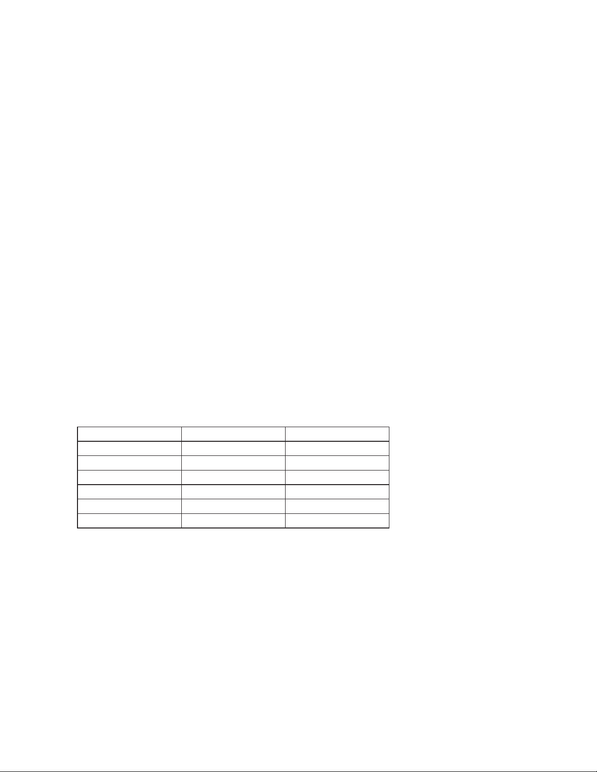
6. EXPANSION VALVE - KM-151BAH, KM-151BWH ONLY ------------------------------ 48
7. WATER REGULATING VALVE - KM-151BWH ONLY ----------------------------------- 50
8. ADJUSTMENT OF WATER REGULATING VALVE - KM-151BWH ONLY --------- 51
9. WATER-COOLED CONDENSER - KM-151BWH ONLY -------------------------------52
10. FAN MOTOR --------------------------------------------------------------------------------------54
11. PUMP MOTOR ------------------------------------------------------------------------------------55
12. WATER VALVE------------------------------------------------------------------------------------56
13. CLEANING VALVE -------------------------------------------------------------------------------57
14. DRAIN VALVE -------------------------------------------------------------------------------------58
15. FLOAT SWITCH ---------------------------------------------------------------------------------- 59
[a] KM-61BAH, KM-101BAH -------------------------------------------------------------------59
[b] KM-151BAH, KM-151BWH ---------------------------------------------------------------- 60
16. BIN CONTROL SWITCH ----------------------------------------------------------------------- 61
17. THERMISTOR ------------------------------------------------------------------------------------64
18. CONTROL BOX ----------------------------------------------------------------------------------65
[a] POWER SWITCH ----------------------------------------------------------------------------66
[b] FUSE --------------------------------------------------------------------------------------------66
[c] FUSE HOLDER -------------------------------------------------------------------------------66
ii
Page 5

[d] CONTROL BOARD -------------------------------------------------------------------------- 66
[e] POWER RELAY ------------------------------------------------------------------------------66
[f] COMPRESSOR CAPACITOR - EXCEPT KM-61BAH -------------------------------67
[g] CONTROL BOARD TRANSFORMER -------------------------------------------------- 67
19. WATER TANK -------------------------------------------------------------------------------------67
20. CUBE GUIDE -------------------------------------------------------------------------------------69
21. SEPARATOR --------------------------------------------------------------------------------------70
22. SPRAY TUBE, WATER SUPPLY PIPE, SPRAY GUIDE -------------------------------70
23. DOOR ----------------------------------------------------------------------------------------------- 71
VI. CLEANING AND MAINTENANCE INSTRUCTIONS --------------------------------------72
1. CLEANING -----------------------------------------------------------------------------------------72
[a] CLEANING PROCEDURE -----------------------------------------------------------------72
[b] SANITIZING PROCEDURE --------------------------------------------------------------- 74
2. MAINTENANCE ---------------------------------------------------------------------------------- 75
[a] EXTERIOR PANELS ------------------------------------------------------------------------75
[b] STORAGE BIN AND SCOOP ------------------------------------------------------------- 75
[c] AIR FILTER ------------------------------------------------------------------------------------ 75
[d] CONDENSER ---------------------------------------------------------------------------------75
3. PREPARING THE ICEMAKER FOR LONG STORAGE --------------------------------76
iii
Page 6
I. SPECIFICATIONS
1. SPECIFICATIONS
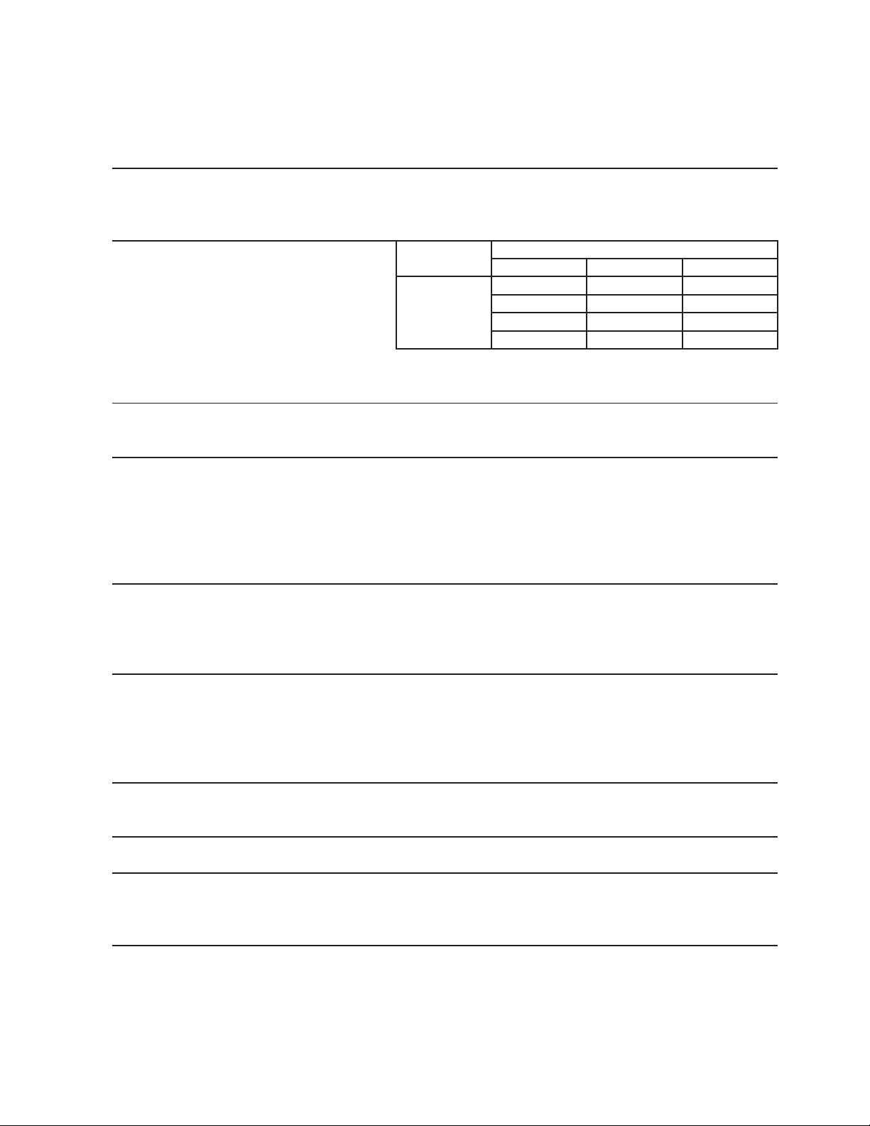
[a] KM-61BAH
AC SUPPLY VOLTAGE 115/60/1
AMPERAGE 3.4A ( 5 Min. Freeze AT 104°F / WT 80°F )
MINIMUM CIRCUIT AMPASITY 15A
MAXIMUM FUSE SIZE 15A
APPROXIMATE ICE PRODUCTION Ambient WATER TEMP. (°F)
PER 24 HR. Temp.(°F) 50 70 90
lbs./day ( kg/day ) 70 *71 (32) 65 (29) 58 (26)
Reference without *marks 80 66 (30) 57 (26) 51 (23)
90 65 (29) *50 (23) 44 (20)
100 64 (29) 49 (22) *38 (17)
SHAPE OF ICE Crescent Cube
ICE PRODUCTION PER CYCLE 1.7 lbs. (0.75 kg) , 80 pcs.
APPROXIMATE STORAGE CAPACITY 38 lbs. (17 kg)
ELECTRIC & WATER CONSUMPTION 90/70°F 70/50°F
ELECTRIC W (kWH/100 lbs.) 220(10.6) 220(7.4)
WATER gal./24HR (gal./100 lbs.) 10(20.6) 23(32.0)
EXTERIOR DIMENSIONS (WxDxH) 17.75" x 24" x 39" (450 x 610 x 990 mm)
Including 6" legs
EXTERIOR FINISH Stainless Steel, Galvanized Steel (Rear)
WEIGHT Net 92 lbs. (42 kg), Shipping 117 lbs. (53 kg)
CONNECTIONS - ELECTRIC Cord Connection
- WATER SUPPLY Inlet 1/2" FPT
- DRAIN Outlet 3/4" FPT
CUBE CONTROL SYSTEM Float Switch
HARVESTING CONTROL SYSTEM Hot Gas and Water, Thermistor and Timer
ICE MAKING WATER CONTROL Timer Controlled. Overflow Pipe
COOLING WATER CONTROL N/A
BIN CONTROL SYSTEM Mechanical Level Switch with Delay
COMPRESSOR Hermetic, Model QA51K13GAU6-E0GS
CONDENSER Air-Cooled, Fin and tube type
EVAPORATOR Vertical type, Stainless Steel and Copper
REFRIGERANT CONTROL Capillary Tube
REFRIGERANT CHARGE R134a, 6.4 oz. (180g)
DESIGN PRESSURE High 250PSIG, Low 150PSIG
P.C. BOARD CIRCUIT PROTECTION High Voltage Cut-out ( Internal )
COMPRESSOR PROTECTION Auto-reset Overload Protector ( Internal )
LOW WATER PROTECTION Float Switch
ACCESSORIES -SUPPLIED Ice Scoop, 6" leg 4 pcs
ACCESSORIES -REQUIRED N/A
OPERATING CONDITIONS VOLTAGE RANGE 104 - 127 V
AMBIENT TEMP. 45-100°F
WATER SUPPLY TEMP. 45- 90°F
WATER SUPPLY PRESSURE 10-113 PSIG
DRAWING NO. (DIMENSION) 3Y2452
We reserve the right to make changes in specifications and design without prior notice.
1
Page 7

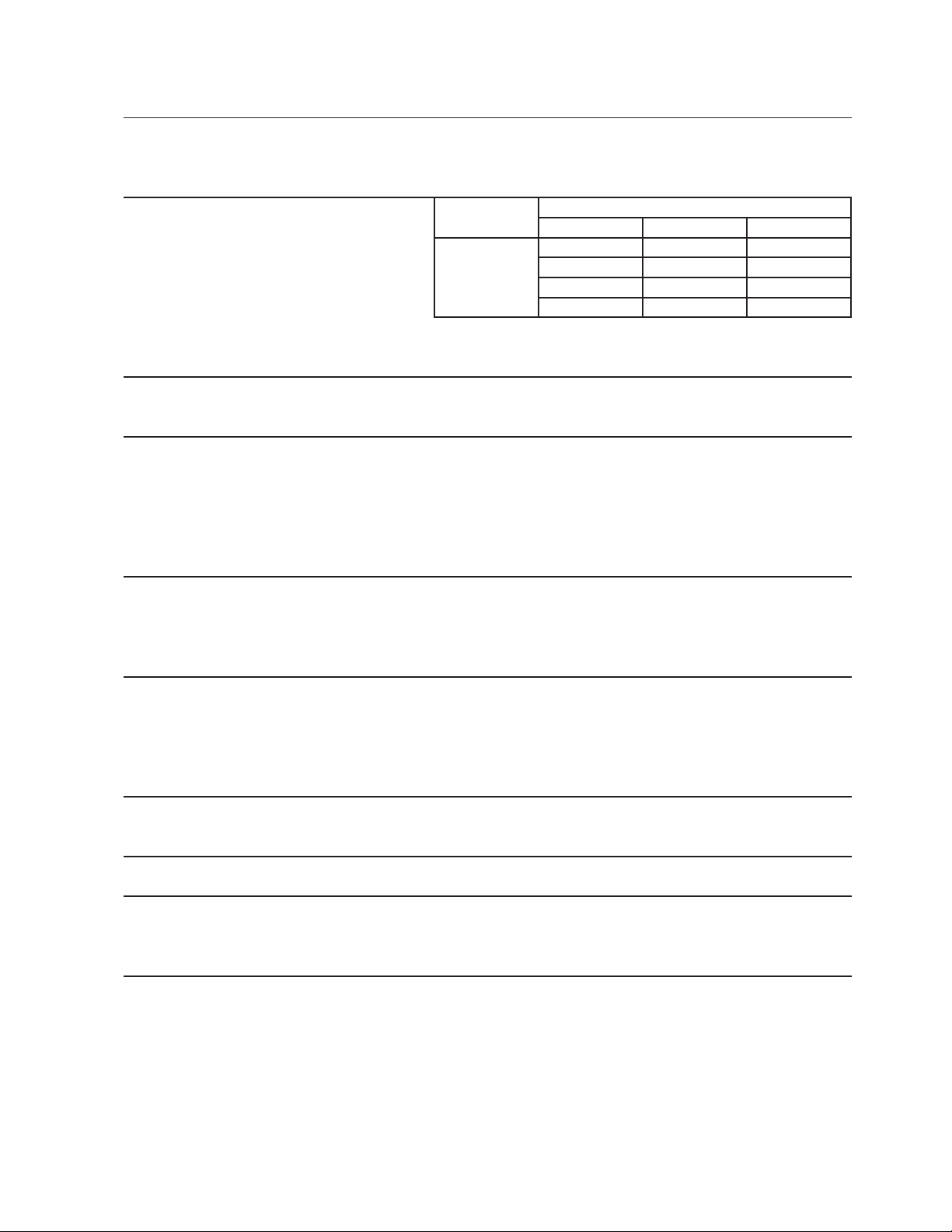
[b] KM-101BAH
AC SUPPLY VOLTAGE 115/60/1
AMPERAGE 5.2A ( 5 Min. Freeze AT 104㐈 / WT 80㐈 )
MINIMUM CIRCUIT AMPASITY 15A
MAXIMUM FUSE SIZE 15A
APPROXIMATE ICE PRODUCTION Ambient WATER TEMP. (°F)
PER 24 HR. Temp.(°F) 50 70 90
lbs./day ( kg/day ) 70 *115 (52) 107 (49) 97 (44)
Reference without *marks 80 109 (50) 97 (44) 87 (40)
90 107 (49) *88 (40) 78 (35)
100 106 (48) 86 (39) *69 (31)
SHAPE OF ICE Crescent Cube
ICE PRODUCTION PER CYCLE 2.31 lbs. (1.05 kg) , 110 pcs.
APPROXIMATE STORAGE CAPACITY 53 lbs. (24 kg)
ELECTRIC & WATER CONSUMPTION 90/70°F 70/50°F
ELECTRIC W (kWH/100 lbs.) 340(9.4) 330(6.8)
WATER gal./24HR (gal./100 lbs.) 20(23.0) 47(40.9)
EXTERIOR DIMENSIONS (WxDxH) 23.75" x 24" x 39" (603 x 610 x 990 mm)
Including 6" legs
EXTERIOR FINISH Stainless Steel, Galvanized Steel (Rear)
WEIGHT Net 106 lbs. (48 kg), Shipping 136 lbs. (62 kg)
CONNECTIONS - ELECTRIC Cord Connection
- WATER SUPPLY Inlet 1/2" FPT
- DRAIN Outlet 3/4" FPT
CUBE CONTROL SYSTEM Float Switch
HARVESTING CONTROL SYSTEM Hot Gas and Water, Thermistor and Timer
ICE MAKING WATER CONTROL Timer Controlled. Overflow Pipe
COOLING WATER CONTROL N/A
BIN CONTROL SYSTEM Mechanical Level Switch with Delay
COMPRESSOR Hermetic, Model QA91K22CAU6-E0GS
CONDENSER Air-Cooled, Fin and tube type
EVAPORATOR Vertical type, Stainless Steel and Copper
REFRIGERANT CONTROL Capillary Tube
REFRIGERANT CHARGE R134a, 7.8 oz. (220g)
DESIGN PRESSURE High 250PSIG, Low 150PSIG
P.C. BOARD CIRCUIT PROTECTION High Voltage Cut-out ( Internal )
COMPRESSOR PROTECTION Auto-reset Overload Protector ( Internal )
LOW WATER PROTECTION Float Switch
ACCESSORIES -SUPPLIED Ice Scoop, 6" leg 4 pcs
ACCESSORIES -REQUIRED N/A
OPERATING CONDITIONS VOLTAGE RANGE 104 - 127 V
AMBIENT TEMP. 45-100°F
WATER SUPPLY TEMP. 45- 90°F
WATER SUPPLY PRESSURE 10-113 PSIG
DRAWING NO. (DIMENSION) 3Y2453
We reserve the right to make changes in specifications and design without prior notice.
2
Page 8
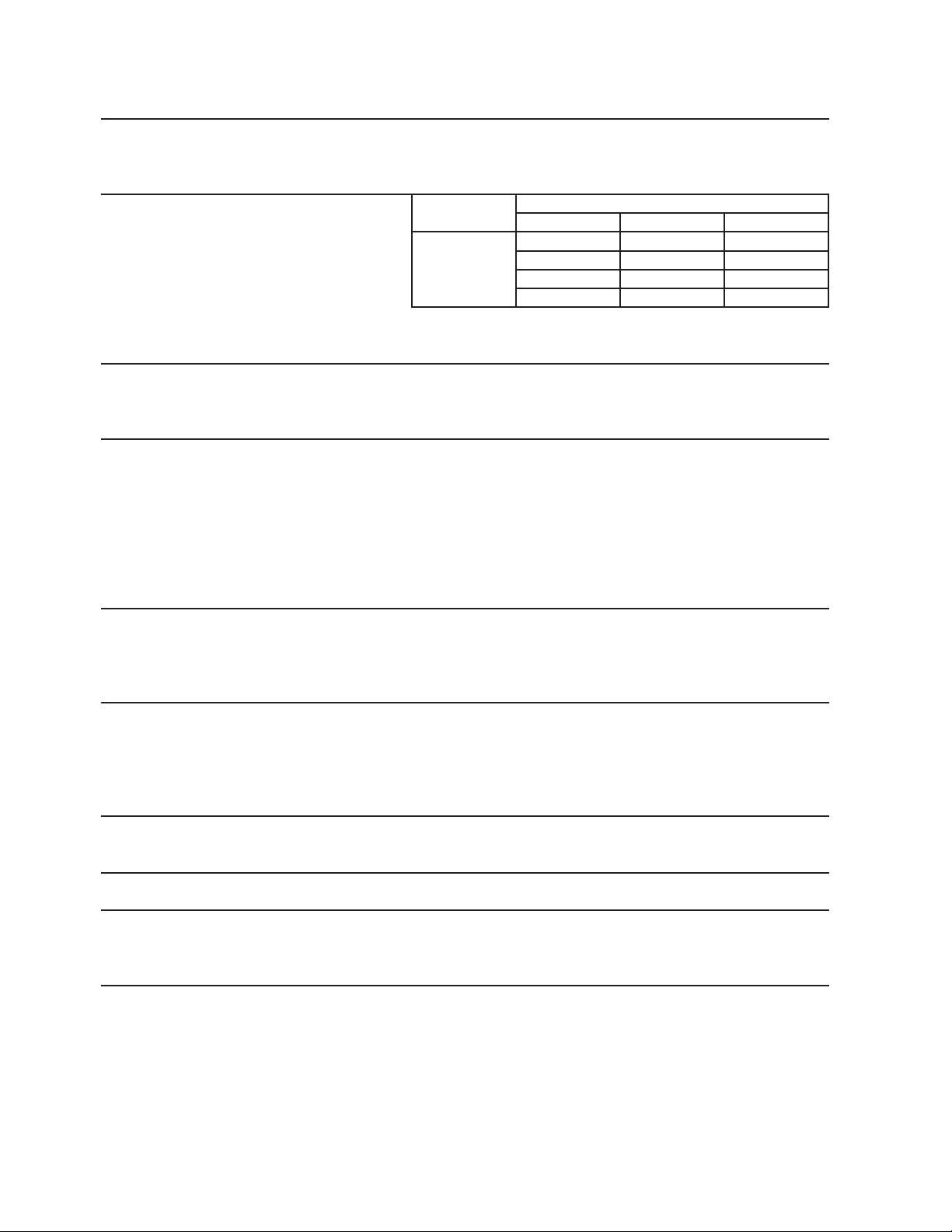
[c] KM-151BAH
AC SUPPLY VOLTAGE 115/60/1
AMPERAGE 7.0A ( 5 Min. Freeze AT 104°F / WT 80°F )
MINIMUM CIRCUIT AMPASITY 15A
MAXIMUM FUSE SIZE 15A
APPROXIMATE ICE PRODUCTION Ambient WATER TEMP. (°F)
PER 24 HR. Temp.(°F) 50 70 90
lbs./day ( kg/day ) 70 *146 (66) 139 (63) 129 (58)
Reference without *marks 80 140 (64) 129 (59) 119 (54)
90 139 (63) *121 (55) 111 (50)
100 137 (62) 119 (54) *101 (46)
SHAPE OF ICE Crescent Cube
ICE PRODUCTION PER CYCLE 2.75 lbs. (1.25 kg) , 130 pcs.
APPROXIMATE STORAGE CAPACITY 78 lbs. (36 kg)
ELECTRIC & WATER CONSUMPTION 90/70°F 70/50°F
ELECTRIC W (kWH/100 lbs.) 420(8.4) 390(6.4)
WATER gal./24HR (gal./100 lbs.) 22(17.8) 50(34.5)
EXTERIOR DIMENSIONS (WxDxH) 23.75" x 28" x 39" (603 x 712 x 990 mm)
Including 6" legs
EXTERIOR FINISH Stainless Steel, Galvanized Steel (Rear)
WEIGHT Net 117 lbs. (53 kg), Shipping 150 lbs. (68 kg)
CONNECTIONS - ELECTRIC Cord Connection
- WATER SUPPLY Inlet 1/2" FPT
- DRAIN Outlet 3/4" FPT
CUBE CONTROL SYSTEM Float Switch
HARVESTING CONTROL SYSTEM Hot Gas and Water, Thermistor and Timer
ICE MAKING WATER CONTROL Timer Controlled. Overflow Pipe
COOLING WATER CONTROL N/A
BIN CONTROL SYSTEM Mechanical Level Switch with Delay
COMPRESSOR Hermetic, Model QA125K29CAU6-E0GS
CONDENSER Air-Cooled, Fin and tube type
EVAPORATOR Vertical type, Stainless Steel and Copper
REFRIGERANT CONTROL Thermostatic Expansion Valve
REFRIGERANT CHARGE R134a, 8.5 oz. (240g)
DESIGN PRESSURE High 250PSIG, Low 150PSIG
P.C. BOARD CIRCUIT PROTECTION High Voltage Cut-out ( Internal )
COMPRESSOR PROTECTION Auto-reset Overload Protector ( Internal )
LOW WATER PROTECTION Float Switch
ACCESSORIES -SUPPLIED Ice Scoop, 6" leg 4 pcs
ACCESSORIES -REQUIRED N/A
OPERATING CONDITIONS VOLTAGE RANGE 104 - 127 V
AMBIENT TEMP. 45-100°F
WATER SUPPLY TEMP. 45- 90°F
WATER SUPPLY PRESSURE 10-113 PSIG
DRAWING NO. (DIMENSION) 3Y2454
We reserve the right to make changes in specifications and design without prior notice.
3
Page 9
[d] KM-151BWH
AC SUPPLY VOLTAGE 115/60/1
AMPERAGE 6.8A ( 5 Min. Freeze AT 104°F / WT 80°F )
MINIMUM CIRCUIT AMPASITY 15A
MAXIMUM FUSE SIZE 15A
APPROXIMATE ICE PRODUCTION Ambient WATER TEMP. (°F)
PER 24 HR. Temp.(°F) 50 70 90
lbs./day ( kg/day ) 70 *146 (66) 141 (64) 136 (62)
Reference without *marks 80 142 (65) 135 (61) 131 (59)
90 141 (64) *130 (59) 125 (57)
100 141 (64) 129 (58) *121 (55)
SHAPE OF ICE Crescent Cube
ICE PRODUCTION PER CYCLE 2.75 lbs. (1.25 kg) , 130 pcs.
APPROXIMATE STORAGE CAPACITY 78 lbs. (36 kg)
ELECTRIC & WATER CONSUMPTION 90/70°F 70/50°F
ELECTRIC W (kWH/100 lbs.) 395(7.3) 390(6.5)
POT. WATER gal./24HR (gal./100 lbs.) 29(25.0) 52(36.0)
COND. WATER gal./24HR (gal./100 lbs.) 181(140) 103(71)
EXTERIOR DIMENSIONS (WxDxH) 23.75" x 28" x 39" (603 x 712 x 990 mm)
Including 6" legs
EXTERIOR FINISH Stainless Steel, Galvanized Steel (Rear)
WEIGHT Net 121 lbs. (55 kg), Shipping 154 lbs. (70 kg)
CONNECTIONS - ELECTRIC Cord Connection
- WATER SUPPLY Inlet 1/2" FPT
- DRAIN Outlet 3/4" FPT
CONDENSER WATER Inlet 1/2" FPT
Outlet 1/2" FPT
CUBE CONTROL SYSTEM Float Switch
HARVESTING CONTROL SYSTEM Hot Gas and Water, Thermistor and Timer
ICE MAKING WATER CONTROL Timer Controlled. Overflow Pipe
COOLING WATER CONTROL N/A
BIN CONTROL SYSTEM Mechanical Level Switch with Delay
COMPRESSOR Hermetic, Model QA125K29CAU6-E0GS
CONDENSER Water-Cooled, tube type
EVAPORATOR Vertical type, Stainless Steel and Copper
REFRIGERANT CONTROL Thermostatic Expansion Valve
REFRIGERANT CHARGE R134a, 10.7 oz. (290g)
DESIGN PRESSURE High 250PSIG, Low 150PSIG
P.C. BOARD CIRCUIT PROTECTION High Voltage Cut-out ( Internal )
COMPRESSOR PROTECTION Auto-reset Overload Protector ( Internal )
LOW WATER PROTECTION Float Switch
ACCESSORIES -SUPPLIED Ice Scoop, 6" leg 4 pcs
ACCESSORIES -REQUIRED N/A
OPERATING CONDITIONS VOLTAGE RANGE 104 - 127 V
AMBIENT TEMP. 45-100°F
WATER SUPPLY TEMP. 45- 90°F
WATER SUPPLY PRESSURE 10-113 PSIG
DRAWING NO. (DIMENSION) 372097
We reserve the right to make changes in specifications and design without prior notice.
4
Page 10
II. GENERAL INFORMATION
1. CONSTRUCTION
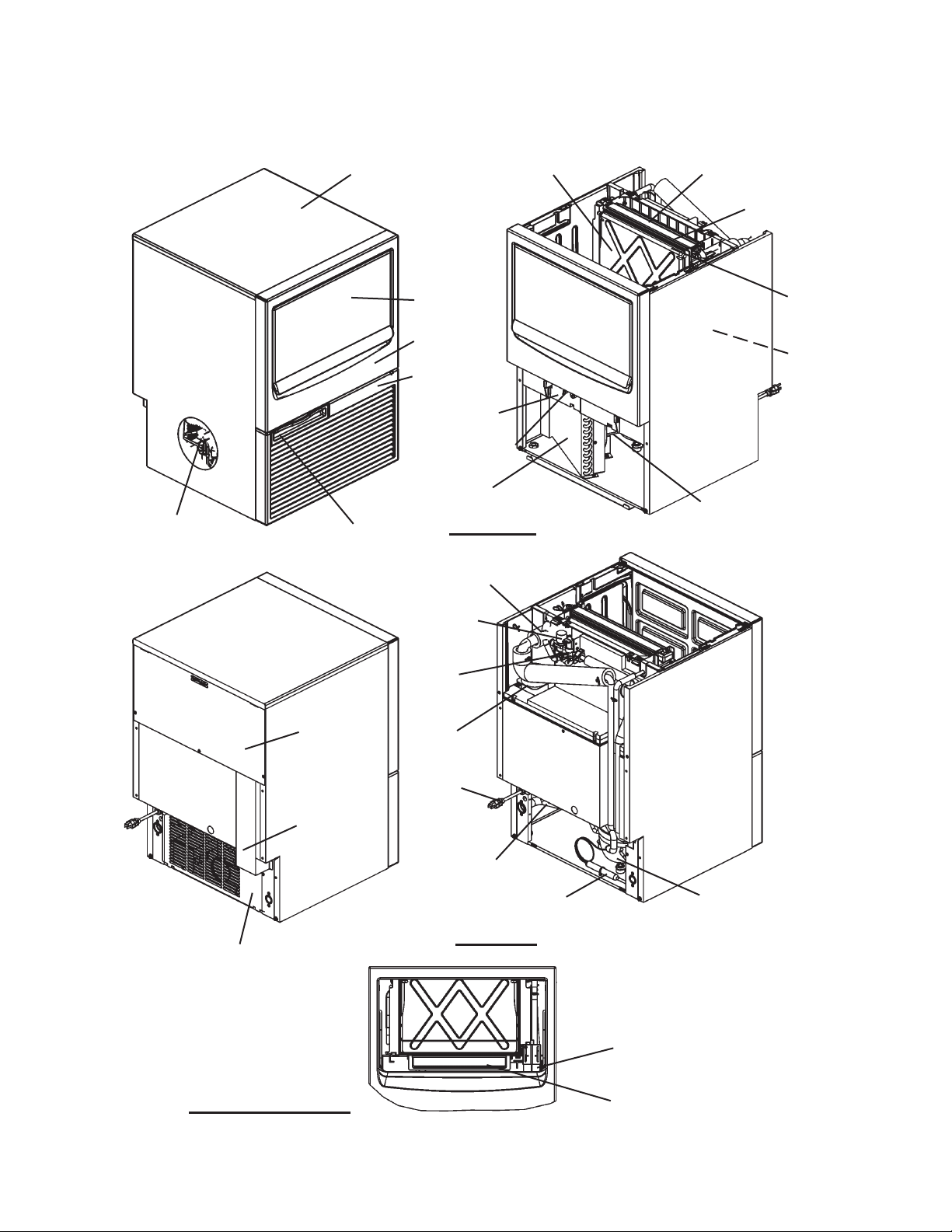
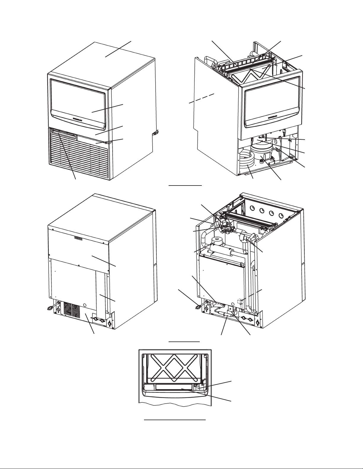
[a] KM-61BAH, KM-101BAH
Top Panel Separator Spray Tube
Evaporator
Door Water Supply
Tube
Front Panel
Tank
Louver
Control Box
Control Switch
Condenser
Fan Motor
Hot Gas Valve Air Filter
Front View
Thermistor
Cleaning
Valve
Water
Valve
Rear Panel Pump
Motor
Power
Supply
Pipe Cover Cord
Drain Valve
Drier Compressor
Rear Cover
Rear View
Float Switch
With Tank Removed
Bin Control Switch
5
Page 11

[b] KM-151BAH
Top Panel Separator Spray Tube
Evaporator
Door Water Supply
Tube
Front Panel
Tank
Louver
Control Box
Control
Switch
Condenser
Compressor
Hot Gas Valve Air Filter
Front View
Fan Motor
Thermistor
Cleaning
Valve
Water
Valve
Rear Panel Pump Expansion Valve
Motor
Power
Supply
Pipe Cover Cord Drier
Drain Valve
Rear Cover
Float Switch
Rear View
Bin Control Switch
With Tank Removed
6
Page 12
[c] KM-151BWH
Top Panel Evaporator Spray Tube
Separator
Water Supply
Tube
Door Tank
Front Panel
Louver Control Switch
Control Box
Fan Motor
Air Filter
Cleaning Valve
Thermistor
Water Valve
Pump Motor Expansion
Valve
Rear Panel
Drain Valve
Power Hot Gas Valve
Supply
Pipe Cover Cord
Rear Cover
Front View
Rear View
Condenser Compressor
Drier Water Regulating Valve
Float Switch
Bin Control Switch
With Tank Removed
7
Page 13
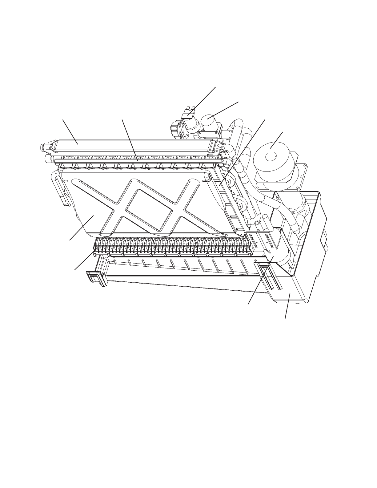
[d] ICEMAKING COMPARTMENT
Water Valve
Cleaning Valve
Spray Tube Water Supply Pipe Evaporator
Pump Motor
Separator
Cube Guide
Float Switch
Water Tank
8
Page 14

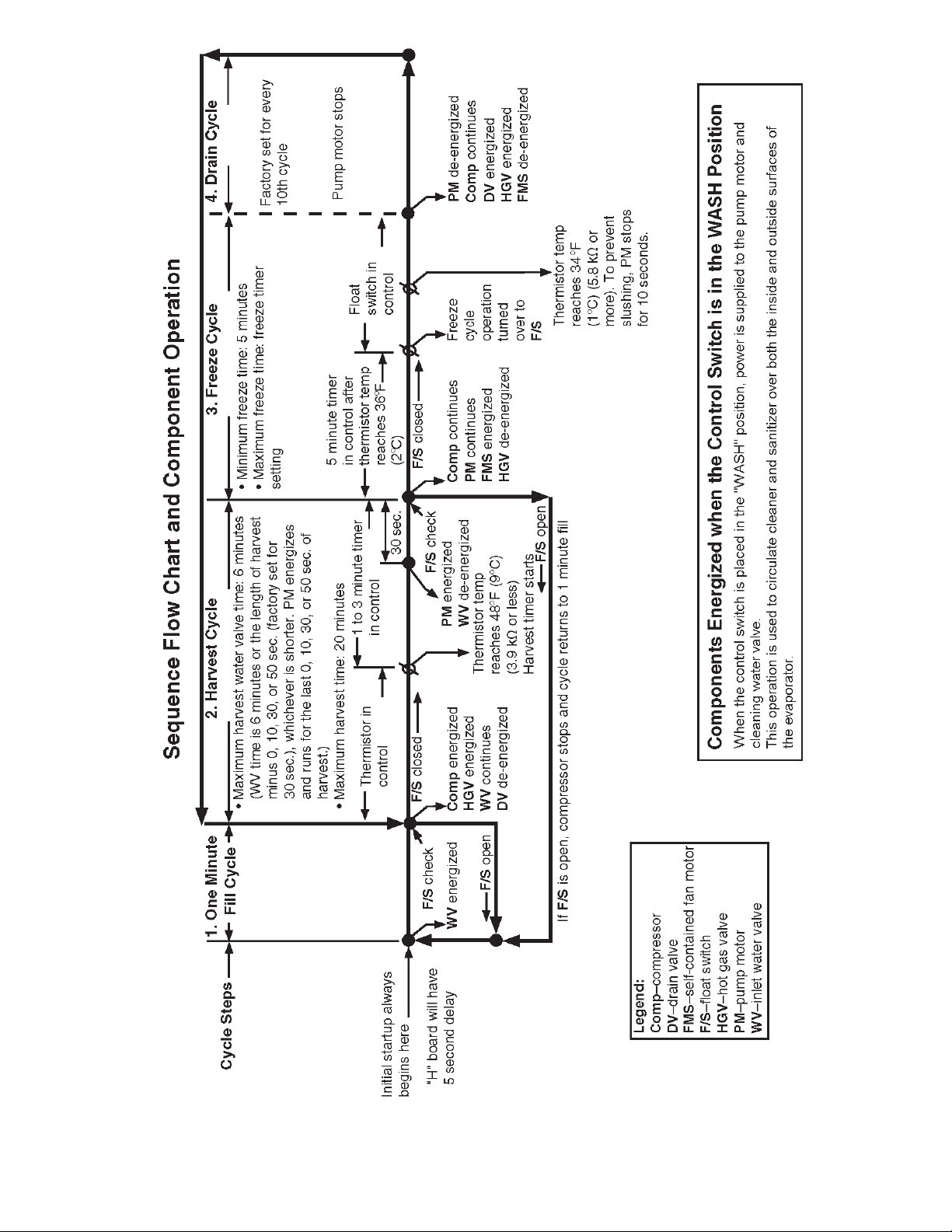
2. SEQUENCE OF OPERATION
The steps in the sequence are as outlined below. When power is supplied, a 5 second
delay occurs at startup. Note that the order of the LEDs from the outer edge of the board
is 5, 6, 8, 4, 7.
[a] ONE MINUTE FILL CYCLE
LED 8 is on. WV opens and the fi ll period begins. After 1 minute, the board checks for
a closed F/S. If F/S is closed, the harvest cycle begins. If not, WV will remain energized
through additional 1 minute cycles until water enters the sump and F/S closes. This
serves as a low water safety to protect the water pump.
[b] INITIAL HARVEST CYCLE
LEDs 5, 6, and 8 are on. WV remains open, Comp energizes, HGV opens, and harvest
begins. As the evaporator warms, the thermistor located on the suction line checks for a
48°F (9°C) temperature. When 48°F (9°C) is reached, a 3.9 k signal turns the harvest
over to the adjustable harvest timer which is factory set for normal conditions. The timer
has settings of 60, 90, 120, and 180 seconds (S1 dip switch 1 & 2). When the harvest
timer completes its count down, the harvest cycle is complete and the freeze cycle
starts. The minimum total time allowed by the board for a complete harvest cycle is 2
minutes. WV is open during harvest for a maximum of 6 minutes or the length of harvest
minus 0, 10, 30, or 50 seconds (adjustable by S1 dip switch 7 & 8), whichever is shorter.
LED 8 goes off when WV closes. PM energizes and runs for the last 0, 10, 30, or 50
seconds of harvest depending on S1 dip switch 7 & 8 setting. LED 7 comes on when
PM energizes. At the end of harvest, the control board checks the position of F/S and
proceeds to the freeze cycle if it is closed or calls for a 1-minute fi ll if it is open.
[c] FREEZE CYCLE
LEDs 5 & 7 are on. Comp continues to run, PM and FMS energize, HGV closes and the
freeze cycle starts. For the fi rst 5 minutes after the thermistor temperature reaches 36°F
(2°C), the control board will not accept a signal from F/S. This minimum freeze period
acts as a short cycle protection. At the end of this period, F/S assumes control. As the
evaporator cools, the thermistor located on the suction line checks the temperature and
PM stops (see “III. 3. TIMING CHART” for details). This is to prevent slushing. As ice
builds on the evaporator the water level in the sump lowers. The freeze continues until
F/S opens and terminates ice production.
9
Page 15

[d] DRAIN CYCLE
LEDs 4, 5, and 6 are on. Comp continues to run, HGV opens, and FMS de-energizes.
PM stops. DV opens for 20 seconds to drain out the water tank. Drain cycle always
occurs on the 2nd harvest after startup. Then, depending on the control board setting,
drain cycle occurs every cycle, or every 2nd, 5th, or 10th cycle (S1 dip switch 5 & 6).
[e] NORMAL HARVEST CYCLE
LEDs 5, 6, and 8 are on. Comp continues to run, HGV remains open and WV opens.
As the evaporator warms, the thermistor reaches 48°F (9°C). The control board then
receives the thermistor's 3.9 k signal and starts the harvest timer. WV is open during
harvest for a maximum of 6 minutes or the length of harvest minus 0, 10, 30, or 50
seconds (adjustable by S1 dip switch 7 & 8), whichever is shorter. LED 8 goes off when
WV closes. PM energizes and runs for the last 0, 10, 30, or 50 seconds of harvest
depending on S1 dip switch 7 & 8 setting. LED 7 comes on when PM energizes. At the
end of harvest, the control board checks the position of F/S and proceeds to the freeze
cycle if it is closed or calls for a 1-minute fi ll if it is open.
The unit continues to cycle through [c], [d], and [e] sequence until the bin control is
activated and shuts the unit down. When the bin control is activated, the "POWER OK"
LED fl ashes.
Legend: Comp–compressor; DV–drain valve; FMS–self-contained fan motor; F/S–fl oat
switch; HGV–hot gas valve; PM–pump motor; WV–inlet water valve
10
Page 16
11
Page 17

3. CONTROL BOARD
* A HOSHIZAKI exclusive solid-state control is employed in KM-61BAH, KM-101BAH,
KM-151BAH and KM-151BWH Crescent Cubers.
* All models are pretested and factory-adjusted.
CAUTION
1. Fragile, handle very carefully.
2. A control board contains integrated circuits, which are susceptible to
failure due to static discharge. It is especially important to touch the
metal part of the unit before handling or replacing the board.
3. Do not touch the electronic devices on the board or the back of the
board to prevent damage to the board.
4. Do not change wiring and connections.
5. Always replace the whole board assembly when it goes bad.
6. Do not short out the power supply to test for voltage.
12
Page 18
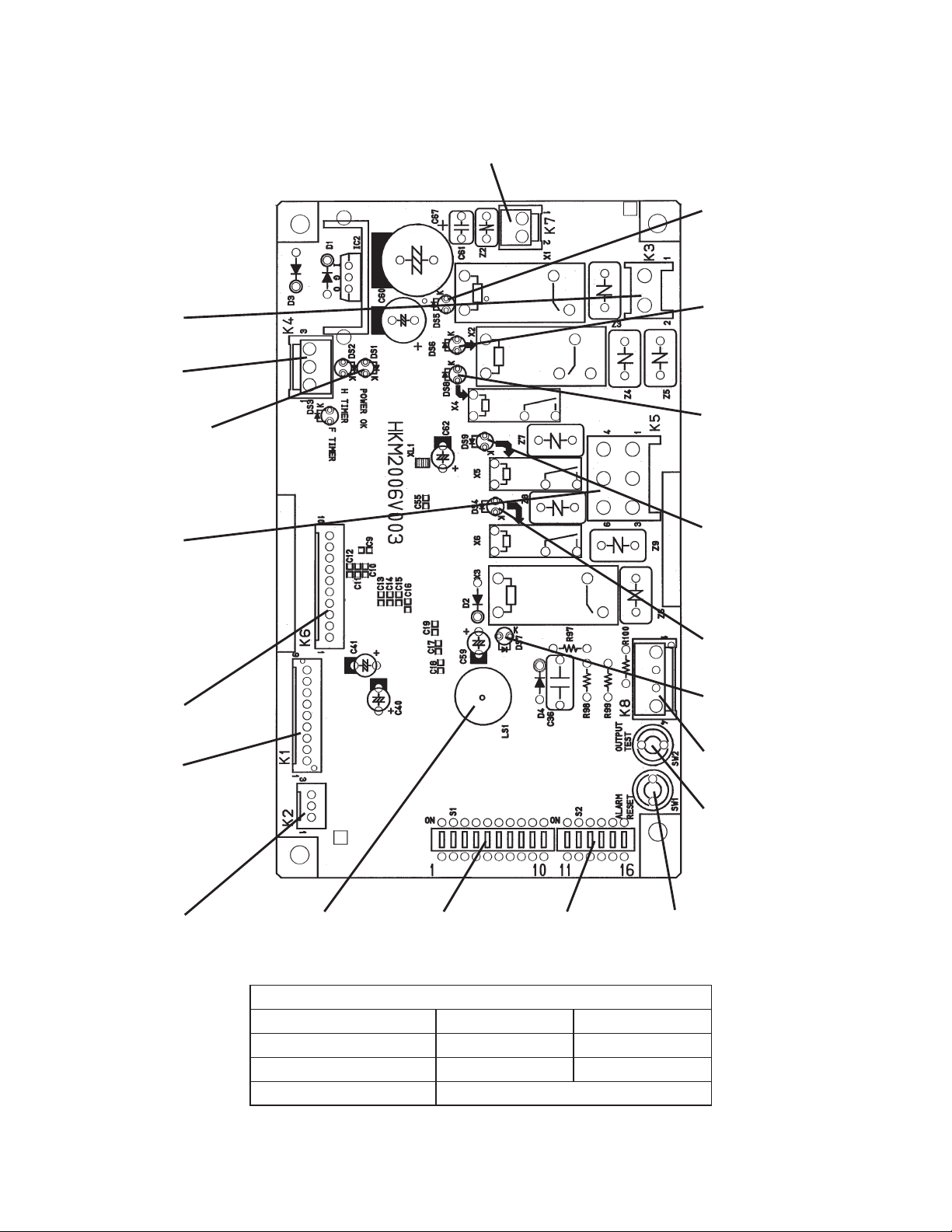
[a] CONTROL BOARD LAYOUT
Connector K7
Transformer
"H" Control Board
Relay LEDs (6)
(indicate which relays
are energized as
listed below)
LED 5 (X1 Relay)
Compressor (Comp)
Remote Fan Motor
(FMR)
Connector K3
Magnetic Contactor
Connector K4
Open
POWER OK LED
(Lights when power is
supplied to the board.
Flashes when bin control
is activated.)
Connector K5
Pins
#1 Fan Motor
#2 Hot Gas Valve
#3 Pump Motor
#4 Water Valve
#5 Open
#6 Drain Valve
Connector K6
Open
Connector K1
Pins
#1, 3 Float Switch
#2 Open
#4, 5 Bin Control
#6, 7 Thermistor
#8, 9 Open
LED 6 (X2 Relay)
Hot Gas Valve (HGV)
Self-Contained Fan
Motor (FMS) (FMS off
when LED on)
LED 8 (X4 Relay)
Inlet Water Valve (WV)
(Harvest Water Valve
(HWV) on units with
two inlet water valves)
LED 9 (X5 Relay)
Freeze Water Valve
(FWV) on units with
two inlet water valves
(service board only)
LED 4 (X6 Relay)
Drain Valve (DV)
LED 7 (X3 Relay)
Pump Motor (PM)
Connector K8
Open
Output Test Button
(used to test relays on
board)
Connector K2
Open
Alarm Buzzer S1 Dip Switch S2 Dip Switch Alarm Reset Button
(service board only)
Control Board
Auxiliary Code V0 or Earlier V1 or Later
Factory Part Number P00013-03 P01771-01
Service Part Number P00013-02 P01771-02
Type HKM2006V003
13
Page 19

[b] FEATURES
a) Maximum Water Supply Period - 6 minutes
The inlet water valve will be open during harvest for 6 minutes or the length of harvest
minus 0, 10, 30, or 50 seconds (adjustable by S1 dip switch 7 & 8), whichever is shorter.
b) Harvest Backup Timer and Freeze Timer
The harvest backup timer shuts down the icemaker if, for two cycles in a row, the
harvest cycle takes more than 20 minutes to complete. The control board will signal this
problem using 2 beeps every 3 seconds.
The freeze timer shuts down the icemaker if, for two cycles in a row, the freeze cycle
takes longer than the time specified to complete. The control board will signal this
problem using 3 beeps every 3 seconds. The time is factory set using S1 dip switch 9 &
10.
The alarm reset button on the control board must be pressed with power on to reset
either of these safeties.
c) High Temperature Safety
The temperature of the suction line in the refrigeration circuit is limited by the high
temperature safety. This protects the unit from excessively high temperatures. If the
evaporator temperature rises above 127°F ± 7°F (53°C ± 4°C), the thermistor operates
the safety. This shuts down the circuit and the icemaker automatically stops.
The control board will signal this problem using 1 beep every 3 seconds. The alarm
reset button on the control board must be pressed with power on to reset the safety.
d) Low Water Safety
The control board checks the position of the fl oat switch at the end of the initial one
minute water fi ll cycle and at the end of each harvest cycle.
If the float switch is in the up position (electrical circuit closed), the control board
changes to the next cycle. If the fl oat switch is in the down position (electrical circuit
open), the control board changes to additional one minute water fi ll cycles until water
enters the sump and the fl oat switch closes. When the fl oat switch closes, the control
board changes to the next cycle. The unit will not start without adequate water in the
sump. This serves as a low water safety to protect the water pump.
For water-cooled model, if the condenser water supply is shut off, the unit is protected
by the high-pressure switch.
e) High Voltage and Low Voltage Cut-outs
The maximum and minimum allowable supply voltages of this icemaker are limited by
the high voltage and low voltage cut-outs.
If miswiring (especially on single phase 3 wire models) causes excessive voltage (147Vac
± 5% or more) on the control board, the high voltage cut-out shuts down the circuit in 3
14
Page 20
seconds and the icemaker automatically stops. The control board will signal this problem
using 7 beeps every 3 seconds.
The icemaker also automatically stops in cases of insuffi cient voltage (92Vac ± 5% or
less). The control board will signal this problem using 6 beeps every 3 seconds.
When the proper supply voltage is resumed, the icemaker automatically starts running
again.
f) LED Lights and Audible Alarm Safeties
The control board includes LED indicator lights, audible alarm safeties, and an output
test feature. The "POWER OK" LED indicates control voltage and will remain on unless
a control voltage problem occurs. The “POWER OK” LED fl ashes continuously when the
bin is full and DV energizes for a maximum of 5 minutes to drain the water tank.
At startup, a 5 second delay occurs to stabilize the circuit. LEDs 4 through 8 energize
and sequence from initial startup as listed in the table below. Note that the order of the
LEDs from the outer edge of the board is 5, 6, 8, 4, 7. For more information, see "2.
SEQUENCE OF OPERATION".
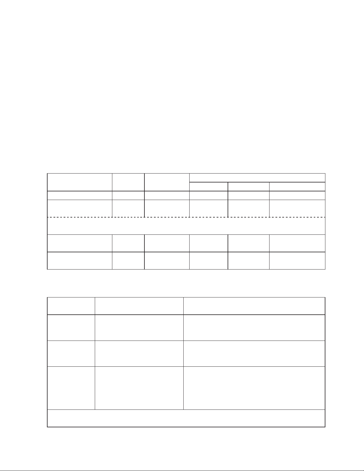
Sequence Step LED
1 Minute Fill Cycle 8 WV 60 seconds
Harvest Cycle 5, 6, 8
Last 0, 10, 30, or 50 seconds (adjustable by dip switch) of harvest, WV de-energizes
and PM energizes (LEDs 5, 6, and 7 are on)
Freeze Cycle 5, 7
Drain 5, 6, 4
Energized
Components
WV, HGV,
Comp
Comp, PM,
FMS
Comp, HGV,
DV
Min. Max. Avg.
2 minutes 20 minutes 3 to 5 minutes
5 minutes
10 seconds 20 seconds
Time LEDs are On
freeze timer
setting
30 to 35 minutes
factory default
setting
The built in safeties shut down the unit and have alarms as listed below.
No. of Beeps
(every 3 sec.)
High Evaporator Temp.
1
2
3
To reset the above safeties, press the "ALARM RESET" button with the power supply
on.
(temperature > 127
(53
Harvest Backup Timer
(harvest > 20 min. for two
cycles in a row)
Freeze Timer
(freeze > specified setting
for two cycles in a row)
Timer is factory set using
S1 dip switch 9 & 10
Type of Alarm Notes
Check for harvest problem (stuck HGV or
°F)
°C)
relay), hot water entering unit, stuck HM, or
shorted thermistor.
Check for open thermistor, HGV not
opening, TXV leaking by, low charge,
ineffi cient Comp, or WRV leaking by.
Check for a float switch stuck closed (up),
WV leaking by, HGV leaking by, PM not
pumping, TXV not feeding properly, low
charge, or ineffi cient Comp.
15
Page 21
6
7
Legend:
Low Voltage
(92Vac
± 5% or less)
High Voltage
(147Vac
± 5% or more)
Comp–compressor; DV–drain valve; FMS–self-contained fan motor; HGV–hot
"POWER OK" LED will turn off if voltage
protection operates.
The control voltage safeties automaticlly
reset when voltage is corrected.
gas valve; PM–pump motor; TXV–thermostatic expansion valve; WRV–water
regulating valve; WV–inlet water valve
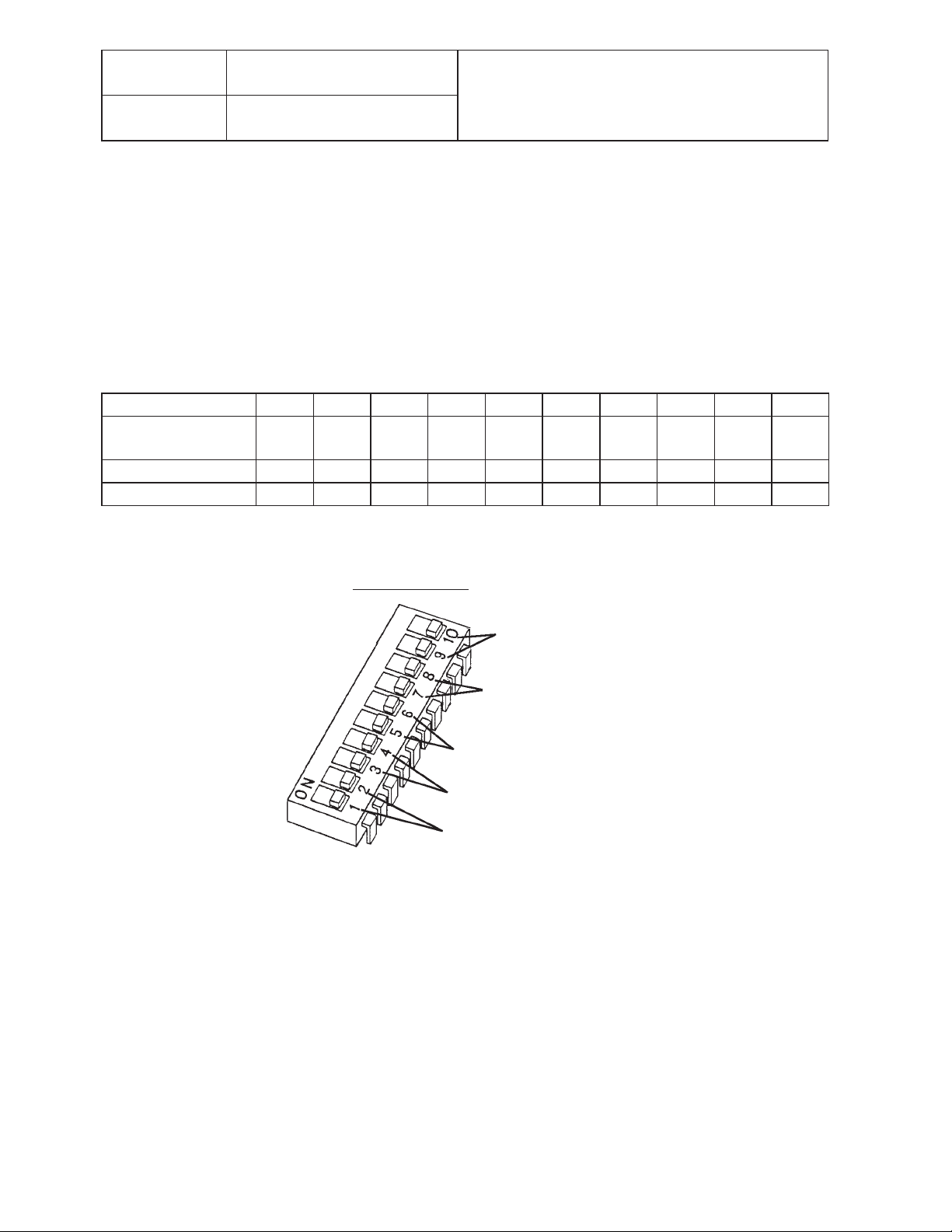
[c] CONTROLS AND ADJUSTMENTS
a) Default Dip Switch Settings
The dip switch is factory-adjusted to the following positions:
S1 Dip Switch No. 12345678910
KM-61BAH
KM-151BAH
OFF OFF ON ON ON ON OFF ON OFF ON
KM-101BAH ON OFF ON ON ON ON OFF ON OFF ON
KM-151BWH OFF OFF ON ON ON ON OFF ON ON OFF
If the S2 dip switch is mounted on the control board, all should be left in the “OFF”
position.
S1 Dip Switch
Freeze Timer (9 & 10)
Water Saver Timer (7 & 8)
Drain Frequency Control (5 & 6)
Drain Timer (3 & 4)
Harvest Timer (1 & 2)
Fig. 1
b) Harvest Timer (S1 dip switch 1 & 2)
The harvest timer starts counting when the thermistor reads 48°F (9°C) at the
evaporator outlet.
No adjustment is required under normal use, as the harvest timer is adjusted to the
suitable position. However, a setting longer than the factory setting may be advised in
cases where the fl ush provided at harvest needs to be prolonged for extra cleaning.
Before changing this setting, call the HOSHIZAKI Technical Support Department at
16
Page 22
1-800-233-1940 for recommendations. Keep in mind that setting the harvest timer to a
longer setting will decrease 24 hour production.
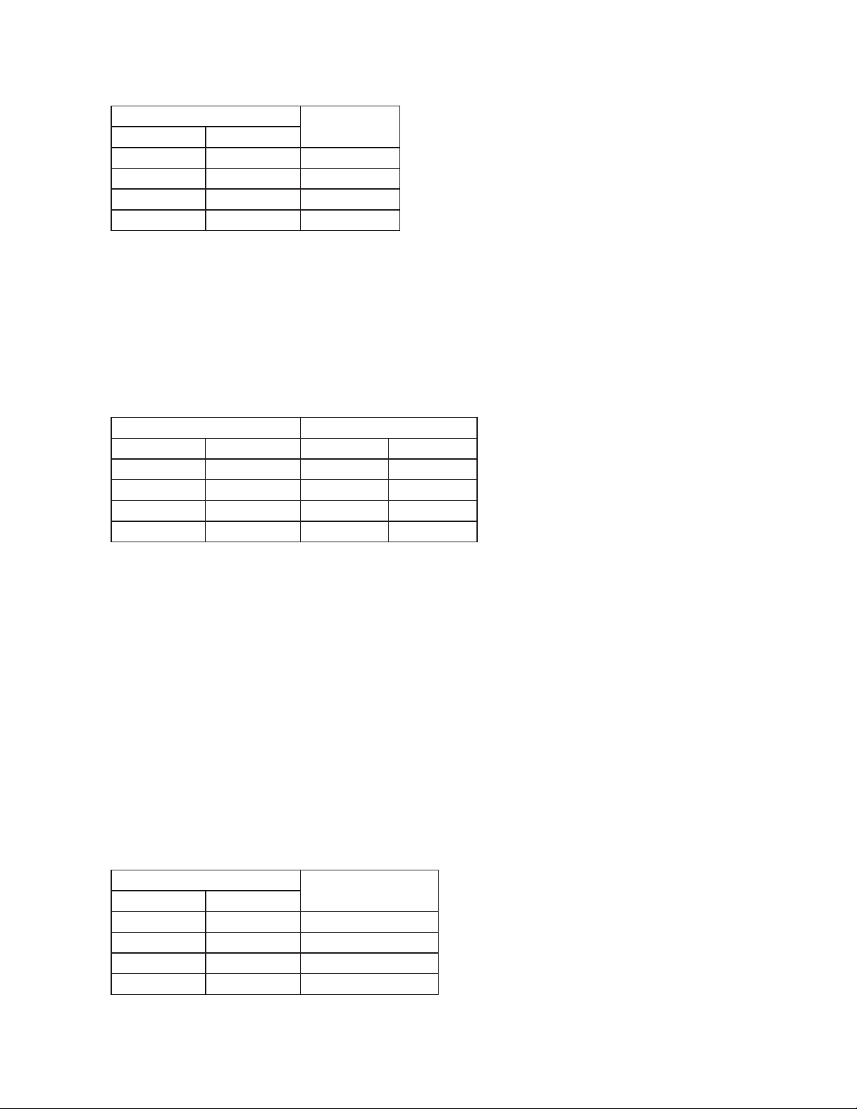
Dip Switch Setting
No. 1 No. 2
OFF OFF 60
ON OFF 90
OFF ON 120
ON ON 180
c) Drain Timer (S1 dip switch 3 & 4)
Once every ten freeze cycles, the drain valve opens to drain the water tank for the
time determined by the drain timer. These switches also determine the time to delay
completion of a defrost cycle, i.e. the minimum defrost time.
Do not change this setting, or the unit will not operate properly or produce high quality
ice.
Dip Switch Setting Time (seconds)
No. 3 No. 4 T1 T2
OFF OFF 10 120
ON OFF 10 180
OFF ON 20 120
ON ON 20 180
Time
(seconds)
T1: Time to drain the water tank
T2: Harvest timer at drain
Drain cycle always occurs on the 2nd harvest after startup. Then, depending on the
drain frequency control setting (dip switch 5 & 6), drain cycle occurs every cycle, or
every 2nd, 5th, or 10th cycle.
d) Drain Frequency Control (S1 dip switch 5 & 6)
The water tank drains at the frequency set by the drain frequency control.
The drain frequency control is factory-adjusted to drain the water tank every 10 cycles,
and no adjustment is required. However, where water quality is bad and the icemaker
needs a drain more often, the drain frequency can be adjusted as shown in the table
below.
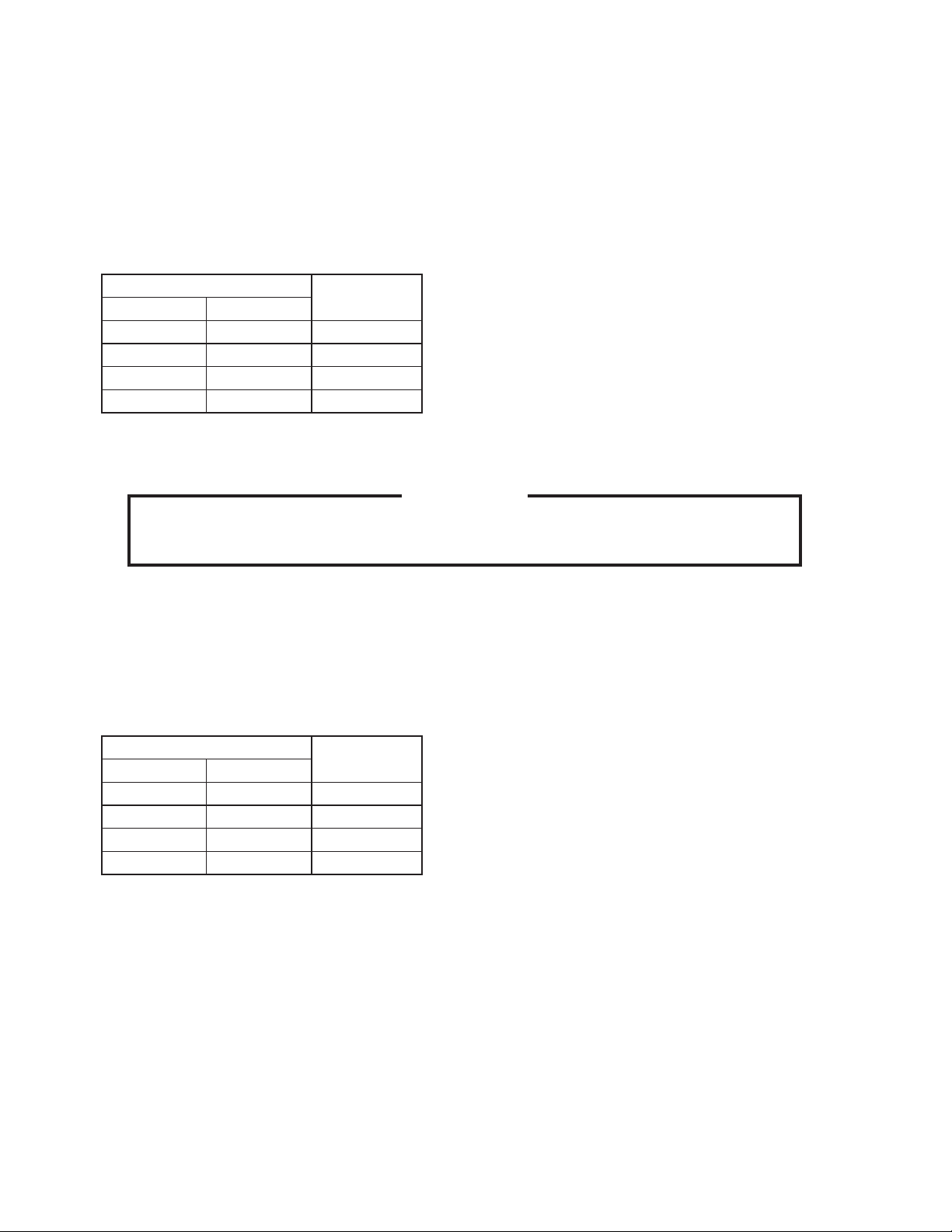
Dip Switch Setting
No. 5 No. 6
OFF OFF every cycle
ON OFF every 2 cycles
OFF ON every 5 cycles
ON ON every 10 cycles
Frequency
17
Page 23
e) Water Saver Timer (S1 dip switch 7 & 8)
The water saver timer allows the water valve to close and the pump motor to circulate
water in the tank during the fi nal part of harvest. The water valve is open during harvest
for a maximum of 6 minutes or the length of harvest minus 0, 10, 30, or 50 seconds
(determined by the water saver timer setting), whichever is shorter. When the water
valve closes, the pump motor energizes and runs for the time determined by the water
saver timer setting.
The water saver timer is factory-adjusted, and no adjustment is required.
Dip Switch Setting
No. 7 No. 8
OFF OFF 0
ON OFF 10
OFF ON 30
ON ON 50
f) Freeze Timer (S1 dip switch 9 & 10)
Time
(seconds)
CAUTION
Adjust to proper specifi cation, or the unit may not operate correctly.
The freeze timer setting determines the maximum allowed freeze time to prevent
possible freeze-up issues. Upon termination of freeze timer, machine initiates the
harvest cycle. After 2 consecutive timer terminations, machine will shut down, possibly
indicating a problem.
The freeze timer is factory adjusted, and no adjustment is required.
Dip Switch Setting
No. 9 No. 10
OFF OFF 60
ON OFF 50
OFF ON 70
ON ON 60
[d] CONTROL BOARD CHECK PROCEDURE
Before replacing a control board that does not show a visible defect and that you
suspect is bad, always conduct the following check procedure. This procedure will help
you verify your diagnosis.
1) Check the dip switch settings to assure that S1 dip switch 3, 4, 7, 8, 9, & 10 are in the
factory default position. S1 dip switch 1, 2, 5, & 6 are cleaning adjustments and the
settings are fl exible.
Time
(minutes)
18
Page 24
2) Move the control switch to the “ICE” position and check for proper control voltage. If
the “POWER OK” LED is on, the control voltage is good. If the “POWER OK” LED
is off, check the control transformer circuit. If no voltage is present, check the power
supply circuit.
3) To perform a relay sequence test, turn on the power switch while pressing the
"OUTPUT TEST" button. The correct lighting sequence should be 5, 6, 7, 8, 4. Some
components (e.g., the compressor) will cycle during test. Each LED comes on for
5 seconds. LED 5 is on while LED 6 is on. Following the output test sequence, the
icemaker will resume normal operation beginning with the 1 minute fi ll cycle.
[e] CONTROL BOARD REPLACEMENT
The dip switches should be adjusted to the factory default settings as outlined in this
manual. If the S2 dip switch is mounted on the control board, all should be left in the “OFF”
position.
4. HARVEST CONTROL - THERMISTOR
A thermistor (semiconductor) is used as a harvest control sensor and anti-slush sensor.
The resistance varies depending on the suction line temperatures. The thermistor
detects the temperature of the evaporator outlet to start the harvest timer or momentarily
stop the pump motor during the freeze cycle. No adjustment is required. If necessary,
check for resistance between thermistor leads, and visually check the thermistor
mounting, located on the suction line next to the evaporator outlet.
Temperature (°F) Temperature (°C) Resistance (k)
0 -18 14.401
10 -12 10.613
32 0 6.000
50 10 3.871
70 21 2.474
90 32 1.633
Check a thermistor for resistance by using the following procedure:
1) Disconnect the connector K1 on the board.
2) Remove the thermistor. See “V. 17. THERMISTOR”.
3) Immerse the thermistor sensor portion in a glass containing ice and water for 2 or 3
minutes.
4) Check for resistance between the thermistor leads. Normal reading is within 3.5 to 7
k. Replace the thermistor if it exceeds the normal reading.
19
Page 25
5. BIN CONTROL
This machine uses a lever-actuated proximity switch (mechanical bin control) to control
the ice level in the storage bin. No adjustment is required.
[a] EXPLANATION OF OPERATION
The bin control is connected to the K1 connector (pins 4 & 5) on the control board. When
the bin control is calling for ice (proximity switch closed; "POWER OK" LED on), the
control board continues icemaking operations. When the bin control is activated in the
bin full position (proximity switch open; "POWER OK" LED fl ashing), the control board
drains and shuts down the unit. However, to prevent incomplete batches of ice from
forming on the evaporator, the control board will only shut down the machine during the
freeze cycle before the fi ve minute timer expires. The fi ve minute timer starts counting
down when the thermistor temperature reaches 36°F (2°C). If, during the freeze cycle,
ice pushes in the lever after the fi ve minute timer expires, the control board will allow the
machine to complete the freeze cycle and the following harvest cycle before shutting
down the machine.
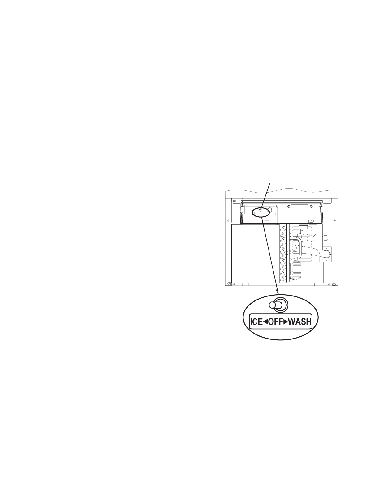
[b] BIN CONTROL CHECK PROCEDURE
1) Clear any ice away from the bin control.
2) Make sure the control switch is in the "ICE" position.
3) Check that the "POWER OK" LED on the control
board is on.
4) Activate the bin control actuator (press the actuator
in). Check that the "POWER OK" LED fl ashes.
5) Disconnect the bin control at the 2-pin connector
attached to the black wires (located in the circle in
Fig. 2) coming from the K1 connector (pins 4 & 5) on
the control board.
6) Check for continuity across the bin control leads.
When calling for ice, the bin control proximity switch
should be closed. If open, replace the bin control.
Activate the bin control actuator (press the actuator
in), check for continuity across the bin control leads.
The bin control proximity switch should be open. If
closed, replace the bin control.
Fig. 2
20
Page 26
7) Reconnect the 2-pin connector. Allow the machine to cycle into the freeze cycle. In
the fi rst 5 minutes of the freeze cycle, activate the bin control actuator (press the
actuator in). The "POWER OK" LED should fl ash and the machine should turn off. If
not, replace the control board.
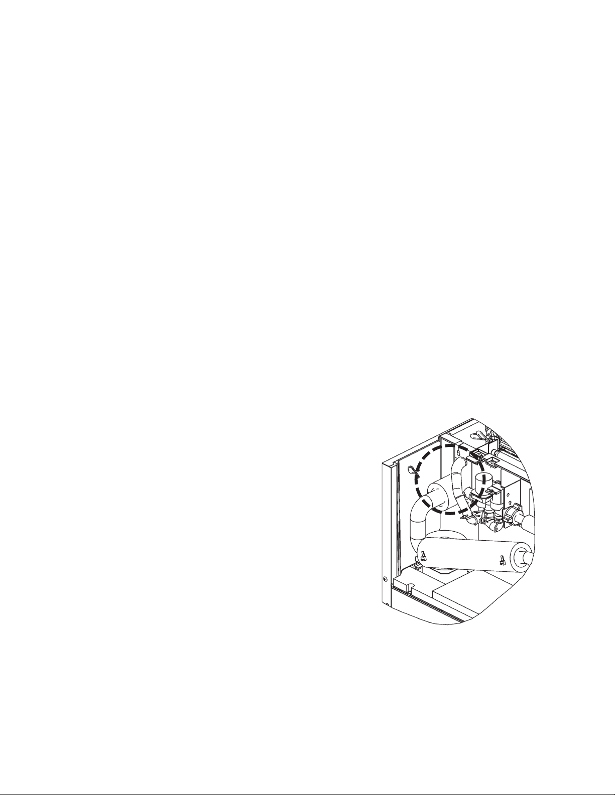
6. SWITCHES
Control Switch
The control switch is located at the left front of the unit. Remove the air fi lter to access
the control switch. This switch is used to place the machine into one of three modes:
“OFF” (center position), “ICE” (right position), and “WASH” (left position).
1) “OFF”
In the “OFF” position, no power is supplied to
the unit. However, to avoid any possible risk of
electrical shock, disconnect the power before
servicing.
2) “ICE”
This position applies power to the unit causing
the automatic icemaking process to begin.
Refer to “2. SEQUENCE OF OPERATION” for
further details.
3) “WASH”
When the control switch is placed in the “WASH”
position, power is supplied to the pump motor
and cleaning water valve. This allows cleaning
and/or sanitizing solutions (see “VI. CLEANING
AND MAINTENANCE INSTRUCTIONS”) to
circulate throughout the water system and
down the inside and outside of the evaporator
plates.
Front View with Louver Removed
Control Switch
Fig. 3
21
Page 27

III. TECHNICAL INFORMATION
1. WATER CIRCUIT AND REFRIGERANT CIRCUIT
[a] KM-61BAH, KM-101BAH
Water Inlet
Capillary Tube
Water Valve
Cleaning Valve
Pump Motor
Float Switch
Spray Tube
Accumulator
Thermistor
Evaporator
Water Tank
Drain Valve
Drain Outlet
Insulation
Insulation
Compressor
Fan
22
Condenser
Water Circuit
Refrigeration Circuit
Drier
Hot Gas
Valve
Page 28

[b] KM-151BAH
Water Inlet
Water Valve
Expansion Valve
Spray Tube
Cleaning Valve
Pump Motor
Hot Gas
Valve
Float Switch
Thermistor
Evaporator
Water Tank
Drain Valve
Drain Outlet
Compressor
Water Circuit
Refrigeration Circuit
Pressure
Switch
Fan
Drier
Condenser
23
Page 29

[c] KM-151BWH
Water Inlet
Water Valve
Expansion Valve
Spray Tube
Cleaning Valve
Pump Motor
Hot Gas
Valve
Float Switch
Compressor
Thermistor
Evaporator
Water Tank
Drain Valve
Drain Outlet
Condenser
Water Supply
Drain
Pressure
Switch
Condenser
Water Circuit
Refrigeration Circuit
Water Regulating
Valve
24
Page 30

2. WIRING DIAGRAM
[a] KM-61BAH
25
Page 31

[b] KM-101BAH
26
Page 32

[c] KM-151BAH, KM-151BWH
27
Page 33

HARVEST CYCLE
c
o
m
Thermistor senses 9°C
after 6 min to 8 min 30 se
in harvest cycle (Ver 3.1
later)
㪍㪇㫊㪼㪺䋺㪢㪤㪄㪍㪈㪙㪘㪟㪃㪈㪌㪈㪙㪘㩿㪮㪀㪟
㪐㪇㫊㪼㪺䋺㪢㪤㪄㪈㪇㪈㪙㪘㪟
Max 6 min Max 6
HARVEST CYCLE
Thermistor senses 9°C after more than
8 min 30 sec in harvest cycle (Ver 3.1
or later)
FREEZE CYCLEHARVEST CYCLEFREEZE CYCLE
HARVEST CYCLE
(AFTER BIN FULL)
BIN FULL
6min 3min 30sec 6min
Max 6 min
90 sec
15 sec
HARVEST CYCLE
(INCLUDING DRAIN)
FREEZE CYCLE
HARVEST CYCLE
FREEZE CYCLE
(INITIAL)
HARVEST CYCLE
ON
9°C
5°C
OFF
PART NAME
3. TIMING CHART
POWER SWITCH
1°C
THERMISTOR
ON
ON
OFF
COMPRESSOR
30sec 10sec 30sec 10sec 30sec 10sec 30sec 30sec 10sec
ON
OFF
or earlier
Program Ver 2.5
FAN MOTOR
30sec 10sec 30sec 10sec 30sec 10sec 30sec 30sec 10sec
ON
OFF
or later
V-0 or earlier)
(Auxiliary Code:
Program Ver 3.2
ON
OFF
V-1 or later)
(Auxiliary Code:
PUMP MOTOR
HOT GAS VALVE
OFF
Max 6 min Max 6 Max 6 min
Max 6 min
5 sec
ON
OFF
WATER VALVE
20sec 20sec
ON
OFF
DRAIN VALVE
ON
ON
OFF
OFF
FLOAT SWITCH
CLEANING VALVE
ON
ON
OFF
RELAY: X1
SWITCH
BIN CONTROL
OFFONOFF
(COMP)
(HV/FM)
RELAY: X2
ON
OFF
(PM)
RELAY: X3
ON
OFF
(WV)
RELAY: X4
CONTROL BOARD
ON
OFF
(DV)
RELAY: X6
28
Page 34

4. PERFORMANCE DATA
[a] KM-61BAH
APPROXIMATE ICE
PRODUCTION PER 24 HR.
lbs./day kg./day 100/38 64 29 49 22 38 17
APPROXIMATE ELECTRIC
CONSUMPTION
watts 100/38
APPROXIMATE WATER
CONSUMPTION PER 24 HR.
gal./day m
FREEZING CYCLE TIME
min. 100/38
HARVEST CYCLE TIME
min. 100/38
HEAD PRESSURE
PSIG kg/cm
SUCTION PRESSURE
PSIG kg/cm
3
/day 100/38 15 0.06 10 0.04 9 0.04
2
G 100/38 121 8.5 159 11.2 185 13.0
2
G 100/38 12 0.9 16 1.1 21 1.5
AMBIENT TEMP.
(°F/°C)
70/21 71 32 65 29 58 26
80/27 66 30 57 26 51 23
90/32 65 29 50 23 44 20
70/21
80/27
90/32
70/21 23 0.09
80/27 20 0.08 14 0.05 15 0.06
90/32 19 0.07 10 0.04 10 0.04
70/21
80/27
90/32
70/21
80/27
90/32
70/21 104 7.3
80/27 115 8.1 139 9.7 153 10.8
90/32 119 8.4 155 10.9 171 12.0
70/21 10 0.7 11 0.8 14 1.0
80/27 11 0.8 13 0.9 17 1.2
90/32 11 0.8 15 1.1 18 1.3
50/10 70/21 90/32
220
220
220
222
31
34
34
37
2.5
2.4
2.4 2.0
2.2
WATER TEMP. (°F/°C)
220
220
220
221
19 0.07 18 0.07
34
39
43
44
2.4
2.2
2.0
2.0
119 8.4 135 9.5
224
226
225
230
41
47
51
58
2.0
2.0
2.0
TOTAL HEAT OF REJECTION FROM CONDENSER
Note: Pressure data is recorded at 5 minutes into freezing cycle.
The data not in
We reserve the right to make changes in specifications and design without prior notice.
bold should be used for reference only.
1,600 BTU/h [AT 90°F (32°C) / WT 70°F (21°C)]
29
Page 35

[b] KM-101BAH
APPROXIMATE ICE
PRODUCTION PER 24 HR.
AMBIENT TEMP.
(°F/°C)
50/10 70/21 90/32
WATER TEMP. (°F/°C)
70/21 115 52 107 49 97 44
80/27 109 50 97 44 87 40
90/32 107 49 88 40 78 35
lbs./day kg./day 100/38 106 48 86 39 69 31
APPROXIMATE ELECTRIC
CONSUMPTION
70/21
80/27
90/32
watts 100/38
APPROXIMATE WATER
CONSUMPTION PER 24 HR.
70/21 47 0.18
80/27 41 0.16 29 0.11 29 0.11
330
332
333
338
333
337
340
344
346
354
356
370
39 0.15 36 0.14
90/32 39 0.15 20 0.08 19 0.07
gal./day m
FREEZING CYCLE TIME
min. 100/38
HARVEST CYCLE TIME
min. 100/38
HEAD PRESSURE
3
/day 100/38 31 0.12 20 0.08 18 0.07
70/21
80/27
90/32
26
28
28
29
70/21
80/27
90/32
2.7
2.6
2.5 2.0
2.3
70/21 109 7.7
28
30
33
34
2.5
2.3
32
35
37
41
2.0
2.0
2.1
2.1
2.0
127 8.9 148 10.4
80/27 123 8.6 150 10.6 170 12.0
90/32 127 8.9 170 12.0 191 13.4
PSIG kg/cm
SUCTION PRESSURE
2
G 100/38 130 9.1 175 12.3 210 14.8
70/21 12 0.8 14 1.0 17 1.2
80/27 14 1.0 17 1.2 20 1.4
90/32 14 1.0 19 1.3 23 1.6
PSIG kg/cm
2
G 100/38 15 1.0 20 1.4 26 1.8
TOTAL HEAT OF REJECTION FROM CONDENSER
2,320 BTU/h [AT 90°F (32°C) / WT 70°F (21°C)]
Note: Pressure data is recorded at 5 minutes into freezing cycle.
The data not in
bold should be used for reference only.
We reserve the right to make changes in specifications and design without prior notice.
30
Page 36

[c] KM-151BAH
APPROXIMATE ICE
PRODUCTION PER 24 HR.
AMBIENT TEMP.
(°F/°C)
50/10 70/21 90/32
WATER TEMP. (°F/°C)
70/21 146 66 139 63 129 58
80/27 140 64 129 59 119 54
90/32 139 63 121 55 111 50
lbs./day kg./day 100/38 137 62 119 54 101 46
APPROXIMATE ELECTRIC
CONSUMPTION
70/21
80/27
90/32
watts 100/38
APPROXIMATE WATER
CONSUMPTION PER 24 HR.
70/21 50 0.19
80/27 44 0.17 31 0.12 32 0.12
390
397
399
400
399
410
420
422
409
420
430
440
42 0.16 39 0.15
90/32 42 0.16 22 0.08 21 0.08
gal./day m
FREEZING CYCLE TIME
min. 100/38
HARVEST CYCLE TIME
min. 100/38
HEAD PRESSURE
3
/day 100/38 33 0.12 21 0.08 20 0.08
70/21
80/27
90/32
21
22
23
23
70/21
80/27
90/32
3.3
3.0
2.9 2.0
2.5
Float Switch 114 8.0
23
24
26
27
2.9
2.4
25
27
29
31
2.0
2.0
2.0
2.0
2.0
128 9.0 148 10.4
80/27 124 8.8 146 10.3 167 11.8
90/32 128 9.0 161 11.3 182 12.8
PSIG kg/cm
SUCTION PRESSURE
2
G 100/38 132 9.3 166 11.7 202 14.2
70/21 12 0.8 13 0.9 14 1.0
80/27 13 0.9 14 1.0 15 1.1
90/32 13 0.9 15 1.1 16 1.1
PSIG kg/cm
2
G 100/38 13 0.9 15 1.1 17 1.2
TOTAL HEAT OF REJECTION FROM CONDENSER
3,840 BTU/h [AT 90°F (32°C) / WT 70°F (21°C)]
Note: Pressure data is recorded at 5 minutes into freezing cycle.
The data not in
bold should be used for reference only.
We reserve the right to make changes in specifications and design without prior notice.
31
Page 37

[d] KM-151BWH
APPROXIMATE ICE
PRODUCTION PER 24 HR.
AMBIENT TEMP.
(°F/°C)
50/10 70/21 90/32
WATER TEMP. (°F/°C)
70/21 146 66 141 64 136 62
80/27 142 65 135 61 131 59
90/32 141 64 130 59 125 57
lbs./day kg./day 100/38 141 64 129 58 121 55
APPROXIMATE ELECTRIC
CONSUMPTION
70/21
80/27
90/32
watts 100/38
APPROXIMATE WATER
CONSUMPTION PER 24 HR.
70/21 155 0.59
80/27 167 0.63 192 0.73 252 0.95
390
391
391
393
391
393
395
396
396
399
400
405
171 0.65 217 0.82
90/32 171 0.65 210 0.79 265 1.00
gal./day m
FREEZING CYCLE TIME
min. 100/38
HARVEST CYCLE TIME
min. 100/38
HEAD PRESSURE
3
/day 100/38 206 0.78 223 0.84 315 1.19
70/21
80/27
90/32
25
26
26
27
70/21
80/27
90/32
3.5
3.3
3.2 2.2
2.8
Float Switch 150 10.5
26
28
29
29
3.2
2.8
28
30
31
33
2.0
2.0
2.5
2.4
2.0
151 10.6 157 11.0
80/27 150 10.6 151 10.6 160 11.3
90/32 151 10.6 152 10.7 160 11.2
PSIG kg/cm
SUCTION PRESSURE
2
G 100/38 154 10.8 154 10.8 167 11.7
70/21 13 0.9 13 0.9 14 1.0
80/27 13 0.9 14 1.0 14 1.0
90/32 13 0.9 14 1.0 15 1.0
PSIG kg/cm
2
G 100/38 13 0.9 14 1.0 15 1.1
TOTAL HEAT OF REJECTION FROM CONDENSER
3,840 BTU/h [AT 90°F (32°C) / WT 70°F (21°C)]
Note: Pressure data is recorded at 5 minutes into freezing cycle.
The data not in
bold should be used for reference only.
We reserve the right to make changes in specifications and design without prior notice.
32
Page 38

IV. SERVICE DIAGNOSIS
1. 10-MINUTE DIAGNOSTIC PROCEDURE
The 10 minute check out procedure is basically a sequence check which can be used
at unit start-up or for system diagnosis. Using this check out procedure will allow you
to diagnose electrical system and component failures in approximately 10 minutes
under normal operating conditions of 70°F or warmer air and 50°F or warmer water
temperatures. Before conducting a 10 minute checkout, check for correct installation,
proper voltage per unit nameplate and adequate water supply. As you go through the
procedure, check to assure the components energize and de-energize correctly. If not,
those components and controls are suspect.
1) Turn power off and access the control box. Clear any ice from the bin control actuator
located in the bin.
2) Turn power on and place the control switch in the "ICE" position. A 5 second delay
occurs. The "POWER OK" LED on the control board comes on. If the "POWER
OK" LED is fl ashing (indicating a full bin), check the bin control. See "II. 5. [b] BIN
CONTROL CHECK PROCEDURE."
3) One Minute Fill Cycle – The inlet water valve is energized. After 1 minute, the control
board checks the fl oat switch. If the fl oat switch is closed, the unit cycles to harvest.
If closed, continue to step 4. If the fl oat switch is open, the unit repeats the 1 minute
fi ll cycle until water enters and the fl oat switch closes (low water safety protection
during initial start up and at the end of each harvest). Diagnosis: If the water valve
does not open, check for no supply voltage at water valve terminals, bad coil, or
plugged screen or external fi lter (no water fl ow). If unit fails to start harvest, check for
open fl oat switch or bad 1 minute timer in board.
4) Initial Harvest Cycle – The inlet water valve remains energized, contactor coil
energizes to start the compressor (and fan motor on a remote condenser unit),
and the hot gas valve energizes. The evaporator warms and the thermistor senses
48°F (9°C). The control board then receives the thermistor's 3.9 k signal and
turns operation of harvest over to the harvest timer. The timer completes counting
(1 to 3 minutes). The unit then cycles to freeze. Diagnosis: Check if compressor
is running, hot gas valve is open, water valve still open. Average harvest cycle at
factory setting is 2 to 3 minutes. How long does initial harvest last? 1.5 minutes after
initial harvest begins, touch the compressor discharge line. Is it hot? If not check
refrigerant pressures and compressor operation. If it is hot, touch the inlet line to the
evaporator. Is it hot? If it is hot and the freeze cycle is not starting, check the harvest
timer adjustment, the thermistor for open circuit, the discharge line temperature,
compressor effi ciency, and if the hot gas valve is fully open.
5) Freeze Cycle – The compressor remains energized, pump motor, (line valve if
applicable), and fan motor energize. The inlet water valve and hot gas valve deenergize. The unit is held in freeze by a 5 minute short cycle protection timer which
33
Page 39

starts after the thermistor temperature reaches 36°F (2°C). After this period, the
freeze cycle operation is transferred to the fl oat switch for freeze termination. During
the fi rst 5 minutes of freeze, confi rm that the evaporator temperature drops. After the
minimum freeze period, disconnect the fl oat switch at the 2-pin connector attached
to the red wires. See Fig. 2 for general location. The unit should immediately switch
to the drain cycle. Diagnosis: If the evaporator is not cold, check to see if the hot
gas valve is still open or if the expansion valve (on KM-151BAH, KM-151BWH only)
is not opening properly, if the water valve is continuing to fi ll the reservoir, if there are
improper unit pressures or an inoperative compressor. If the unit remains in freeze
with the fl oat switch removed, replace the board.
Note: Normal freeze cycle will last 0 to 40 minutes depending on model and conditions.
Cycle times and pressures should follow performance data provided in this
manual.
6) Drain Cycle – The compressor remains energized, the hot gas valve energizes, the
fan motor de-energizes. The drain valve energizes, allowing water to drain from the
tank for 20 seconds. This removes contaminants from the water tank. Diagnosis: If
the drain valve does not open, check the circuit. Check for proper voltage. If water
does not drain out, check and clean the tubing at the drain valve and then check and
clean the valve assembly.
7) Normal Harvest Cycle – same as the initial harvest cycle – Return to step 4.
Note: Unit continues to cycle until bin control is satisfi ed or power is turned off. (The
drain cycle can be adjusted to occur every cycle, or every 2, 5, or 10 cycles. The
factory default is every 10 cycles.) The unit always restarts at the 1 minute fi ll
cycle.
34
Page 40

2. NO ICE PRODUCTION
PROBLEM POSSIBLE CAUSE REMEDY
[1] The icemaker
will not start.
a) Power Supply
b) Fuse (inside fused
disconnect, if any)
e) High Pressure
Control (KM-151
only)
f) Transformer 1. Thermal fuse blown out
g) Wiring to Control
Board
h) Thermistor 1. Leads shorted or open
i) Hot Gas Solenoid
Valve
j) Water Supply Line 1. Water supply off and
k) Inlet Water Valve
l) Control Board 1. Defective. 1. See “II. 3. [d] CONTROL
1. OFF position. 1. Move to ON position.
2. Loose connections. 2. Tighten.
3. Bad contacts. 3. Check for continuity and
replace.
4. Voltage too high. 4. Check and get
recommended voltage.
5. Unplugged. 5. Plug in.
1. Blown out. 1. Check for short circuit an d
replace.
1. OFF or WASH position. 1. Move to ICE position. c) Control Switch
2. Bad contacts. 2. Check for continuity and
replace.
1. Tripped with bin filled
with ice.
2. Defective reed switch. 2. Check for continuity and
1. Bad contacts. 1. Check for continuity and
or coil winding opened.
1. Loose connections or
open.
and High Temperature
Safety operates. If
open, unit will start but
have long harvest cycle.
1. Continues to open in
freeze cycle and High
Temperature Safety
operates.
water supply cycle does
not finish.
1. Mesh filter or orifice
gets clogged and water
supply cycle does not
finish.
2. Coil winding opened. 2. Replace.
3. Wiring to Water Valve. 3. Check for loose
1. Remove ice. d) Bin Control Switch
replace.
replace.
1. Replace.
1. Check for continuity and
replace.
1. See “II. 4. HARVEST
CONTROL THERMISTOR”.
1. Check for power off in
freeze cycle and replace.
1. Check and get
recommended pressure.
Check for water supply.
1. Clean. Replace if
necessary.
connection or open, and
replace.
BOARD CHECK
PROCEDURE”.
35
Page 41

PROBLEM POSSIBLE CAUSE REMEDY
[2] Water
continues to
be supplied,
and the
icemaker will
not start.
a) Float Switch
1. Connector
disconnected.
2. Leads opened or
defective switch.
3. Float does not move
freely.
1. Reconnect.
2. Check and replace.
3. Clean or replace.
b) Control Board 1. Defective. 1. Replace.
[3] Compressor
will not start or
operates
intermittently.
b) High Pressure
Control (KM-151
only)
1. WASH position. 1. Move to ICE position. a) Control Switch
2. Bad contacts. 2. Check and replace.
1. Dirty Air Filter or
1. Clean.
Condenser.
2. Ambient temperature
too warm.
3. Refrigerant
2. Reduce ambient
temperature.
3. Recharge.
overcharged.
4. Fan not operating. 4. See chart 2 - [6].
5. Refrigerant line or
5. Clean and replace Drier.
components plugged.
6. Condenser water
pressure too low or off
6. Check and get
recommended pressure.
(KM-151BWH only).
c) Overload
Protector
1. Bad contacts. 1. Check for continuity and
replace.
2. Voltage too low. 2. Increase voltage.
3. Refrigerant overcharged
3. Recharge.
or undercharged.
1. Bad contacts. 1. Check and replace. d) Starter
2. Coil winding opened. 2. Replace.
e) Start Capacitor 1. Defective. 1. Replace.
f) Power Relay
1. Bad contacts. 1. Check for continuity and
replace.
2. Coil winding opened. 2. Replace.
g) Compressor
1. Wiring to Compressor. 1. Check for loose
connection or open, and
replace.
2. Defective. 2. Replace.
3. Protector tripped. 3. Reduce temperature and
verify cause.
h) Control Board 1. Defective. 1. See “II. 3. [d] CONTROL
BOARD CHECK
PROCEDURE”.
[4] Water
continues to
be supplied in
freeze cycle.
i) Condenser, Air
Filter
a) Inlet Water Valve 1. Diaphragm does not
b) Control Board 1. Defective. 1. See “II. 3. [d] CONTROL
1. Clogged with dirt and
dust.
close.
1. Clean and unclog.
1. Check for water leaks
with icemaker off.
Replace if necessary.
BOARD CHECK
PROCEDURE”.
36
Page 42

PROBLEM POSSIBLE CAUSE REMEDY
[5] No water
comes from
Spray Tubes.
Water Pump
will not start, or
freeze cycle
time is too
short.
a) Water Supply Line 1. Water press ure too low
and water level in Water
Tank too low.
b) Inlet Water Valve 1. Dirty mesh filter or
orifice and water level in
Water Tank too low.
c) Water System
1. Water leaks. 1. Check connections for
1. Check and get
recommended pressure.
1. Clean.
water leaks, and replace.
2. Clogged. 2. Clean.
d) Pump Motor
1. Motor winding opened. 1. Replace.
2. Bearing worn out. 2. Replace.
3. Wiring to Pump Motor. 3. Check for loose
connection or open, and
replace.
4. Defective Capacitor. 4. Replace.
5. Defective or bound
5. Replace and clean.
impeller.
e) Control Board 1. Defective. 1. See “II. 3. [d] CONTROL
BOARD CHECK
PROCEDURE”.
[6] Fan Motor will
not start, or is
not operating.
a) Fan Motor
1. Motor winding opened. 1. Replace.
2. Bearing worn out. 2. Replace.
3. Wiring to Fan Motor. 3. Check for loose
connection or open, and
replace.
4. Fan blade bound
4. Check and replace.
(locked Fan Motor).
b) Control Board 1. Defective. 1. See “II. 3. [d] CONTROL
BOARD CHECK
PROCEDURE”.
[7] All
components
run but no ice
is produced.
a) Refrigerant
1. Undercharged. 1. Check for leaks and
recharge.
2. Air or moisture trapped. 2. Replace Drier, and
recharge.
b) Compressor 1. Defective. 1. Replace.
c) Hot Gas Solenoid
Valve
d) Water Supply Line
(KM-151BWH
only)
1. Continues to open in
freeze cycle.
1. Condenser water
pressure too low or off
and Pressure Control
1. Check and replace.
1. Check and get
recommended pressure.
opens and closes
frequently.
e) Water Regulating
Valve
(KM-151BWH
1. Set too high. 1. Adjust or replace. See “VI.
7. WATER REGULATING
VALVE”.
only)
37
Page 43

3. EVAPORATOR IS FROZEN UP
PROBLEM POSSIBLE CAUSE REMEDY
[1] Freeze cycle
time is too
long.
[2] All ice formed
on Evaporator
does not fall
into bin in
harvest cycle.
[3] Others
1. Leads shorted or
defective switch.
2. Float does not move
freely.
b) Inlet Water Valve 1. Diaphragm does not
close.
c) Control Board 1. Defective. 1. See “II. 3. [d] CONTROL
a) Evaporator 1. Scaled up. 1. Clean.
b) Water Supply Line 1. Water pressure too low. 1. Check and get
1. Dirty mesh filter or
orifice.
2. Diaphragm does not
close.
d) Ambient and/or
water temperature
e) Thermistor 1. Out of position or loose
f) Control Board
b) Water System 1. Dirty. 1. Clean.
c) Refrigerant 1. Undercharged. 1. Check for leaks and
(KM-151 only)
e) Hot Gas Solenoid
Valve
f) Water Supply Line 1. Too small; requires 3/8”
g) Water Filter 1. Flow rate too small. 1. Replace with filter that
1. Too cool. 1. Increase temperature.
attachment.
1. Harvest Timer is set too
short.
2. Defective. 2. See “II. 3. [d] CONTROL
1. Clogged. 1. Clean. a) Spray Tubes
2. Out of position. 2. Place in position.
1. Bulb out of position or
loose attachment.
2. Defective. 2. Replace.
1. Coil winding opened. 1. Replace.
2. Plunger does not move. 2. Replace.
3. Wiring to Hot Gas
Valve.
OD line dedicated per
machine.
1. Check and replace. a) Float Switch
2. Clean or replace.
1. Check for water leaks
with icemaker off.
Replace if necessary.
BOARD CHECK
PROCEDURE”.
recommended pressure.
1. Clean. c) Inlet Water Valve
2. Check for water leaks
with icemaker off.
Replace if necessary.
1. See “VI. 16.
THERMISTOR”.
1. Adjust longer, referring to
“II. 4. HARVEST
CONTROL THERMISTOR”.
BOARD CHECK
PROCEDURE”.
recharge.
1. Place in position. d) Expansion Valve
3. Check for loose
connection or open, and
replace.
1. Increase water supply line
size.
has larger flow rate.
38
Page 44

4. LOW ICE PRODUCTION
PROBLEM POSSIBLE CAUSE REMEDY
[1] Freeze cycle
time is long.
[2] Harvest cycle
time is long.
a) See chart 2 - [3] and check dirty Air Filter or Condenser, ambient or water
temperature, water pressure, Condenser Water Regulating Valve
(KM-151BWH) and refrigerant charge.
b) See chart 3 - [1] and check Float Switch, Inlet Water Valve, and Control
Board.
a) See chart 3 - [2] and check Control Board, Thermi stor, Evaporator, ambient
and/or water temperature, water supply line, and Inlet Water Valve.
5. ABNORMAL ICE
PROBLEM POSSIBLE CAUSE REMEDY
[1] Small cubes
[2] Cloudy or
irregular cubes
a) Cube Guide,
Water Tank
b) See chart 2 - [5] and check water supply line, Inlet Water Valve, water system,
Pump Motor, and Control Board.
a) See chart 3 - [1] and - [3] and check Float Switch, Inlet Water Valve, Control
Board, Spray Tubes, water system, refrigerant charge and Expansion Valve.
b) Spray Guide 1. Dirty. 1. Clean.
c) Water Quality 1. High hardness or
1. Out of position.
Circulated water falls
into bin.
contains impurities.
1. Check that Cube Guide is
properly installed on
Water Tank and tank is
fixed securely with snaps.
1. Install a water filter or
softener.
39
Page 45

6. OTHER
PROBLEM POSSIBLE CAUSE REMEDY
[1] Icemaker will
not stop when
bin is filled with
ice.
[2] Abnormal
noise
[3] Ice in Storage
Bin often
melts.
a) Bin Control Switch
b) Control Board 1. Defective. 1. See “II. 3. [d] CONTROL
a) Pump Motor 1. Bearings worn out. 1. Replace.
b) Fan Motor
d) Refrigerant Lines 1. Rub or touch li nes or
a) Bin Drain 1. Plugged. 1. Clean.
1. Completely
disconnected and
dropped inside bin.
2. Detector broken. 2. Replace.
3. Detector out of position. 3. Place in position.
4. Defective reed switch. 4. Check for continuity and
5. Reed switch out of
position.
6. Magnet disconnected
from Detector.
1. Bearings worn out. 1. Replace.
2. Fan blade deformed. 2. Replace fan blade.
3. Fan blade does not
move freely.
1. Bearings worn out, or
cylinder valve broken.
2. Mounting pad out of
position or loose
hold-down bolt.
other surfaces.
1. Place in position.
replace.
5. Place in position.
6. Place in position.
BOARD CHECK
PROCEDURE”.
3. Replace.
1. Replace. c) Compressor
2. Reinstall.
1. Reposition.
40
Page 46

V. REMOVAL AND REPLACEMENT
1. SERVICE FOR REFRIGERANT LINES
[a] SERVICE INFORMATION
1) Allowable Compressor Opening Time and Prevention of Lubricant Mixture
[R134a]
The compressor must not be opened more than 15 minutes in replacement or service.
Do not mix lubricants of different compressors even if both are charged with the same
refrigerant, except when they use the same lubricant.
2) Treatment for Refrigerant Leak [R134a]
If a refrigerant leak occurs in the low side of an ice maker, air may be drawn in. Even
if the low side pressure is higher than the atmospheric pressure in normal operation,
a continuous refrigerant leak will eventually lower the low side pressure below the
atmospheric pressure and will cause air suction. Air contains a large amount of moisture,
and ester oil easily absorbs a lot of moisture. If an ice maker charged with R134a has
possibly drawn in air, the drier must be replaced. Be sure to use a drier designed for
R134a.
3) Handling of Handy Flux [R134a]
Repair of the refrigerant circuit requires brazing. It is no problem to use the same handy
flux that has been used for the current refrigerants. However, its entrance into the
refrigerant circuit should be avoided as much as possible.
4) Oil for Processing of Copper Tubing [R134a]
When processing the copper tubing for service, wipe off oil, if any used, by using alcohol
or the like. Do not use too much oil or let it into the tubing, as wax contained in the oil
will clog the capillary tubing.
5) Service Parts for R134a
Some parts used for refrigerants other than R134a are similar to those for R134a. But
never use any parts unless they are specified for R134a because their endurance
against the refrigerant have not been evaluated. Also, for R134a, do not use any parts
that have been used for other refrigerants. Otherwise, wax and chlorine remaining on
the parts may adversely affect R134a.
6) Replacement Copper Tubing [R134a]
The copper tubes currently in use are suitable for R134a. But do not use them if oily
inside. The residual oil in copper tubes should be as little as possible. (Low residual oil
41
Page 47

type copper tubes are used in the shipped units.)
7) Evacuation, Vacuum Pump and Refrigerant Charge [R134a]
Never allow the oil in the vacuum pump to flow backward. The vacuum level and
vacuum pump may be the same as those for the current refrigerants. However, the
rubber hose and gauge manifold to be used for evacuation and refrigerant charge
should be exclusively for R134a.
8) Refrigerant Leak Check
Refrigerant leaks can be detected by charging the unit with a little refrigerant, raising
the pressure with nitrogen and using an electronic detector. Do not use air or oxygen
instead of nitrogen for this purpose, or rise in pressure as well as in temperature may
cause R134a to suddenly react with oxygen and explode. Be sure to use nitrogen to
prevent explosion.
[b] REFRIGERANT RECOVERY
No refrigerant Access Valve is provided in the unit. Install a proper Access Valve on the
low-side line (ex. Compressor Process Pipe). Recover the refrigerant from the Access
Valve, and store it in a proper container. Do not discharge the refrigerant into the
atmosphere.
[c] EVACUATION AND RECHARGE
1) Attach Charging Hoses, a Service Manifold and a Vacuum Pump to the system.
2) Turn on the Vacuum Pump.
3) Allow the Vacuum Pump to pull down to a 29.9”Hg vacuum. Evacuating period
depends on the pump capacity.
4) Close the Low-side Valve on the Service Manifold.
5) Disconnect the Vacuum Pump, and attach a Refrigerant Charging Cylinder.
Remember to loosen the connection, and purge the air from the Hose. See the
Nameplate for the required refrigerant charge.
6) Open the Low-side Valve. Do not invert the Charging Cylinder. A liquid charge will
damage the Compressor.
7) Turn on the icemaker when charging speed gets slow. Turn off the icemaker when
2
the Low-side Gauge shows approximately 0 kg/cm
. Do not run the icemaker at
vacuum pressures. Close the Low-side Valve when the Charging Cylinder gets
empty.
42
Page 48

8) Repeat steps 4) through 7), if necessary, until the required amount of refrigerant has
entered the system.
9) Close the Refrigerant Access Valve, and disconnect the Hoses, Service Manifold,
etc.
10) Cap the Access Valve to prevent possible leak.
Depressed
Cap
Access Valve
OPEN
Fig. 4
2. BRAZING
DANGER
1. Refrigerant R134a itself is not explosive or poisonous. However,
when exposed to high temperatures (open flames), R134a can be
decomposed to form hydrofluoric acid and carbonyl fluoride both of
which are hazardous.
2. Always recover the refrigerant and store it in a proper container. Do not
discharge the refrigerant into the atmosphere.
3. Do not use silver alloy or copper alloy containing Arsenic.
4. Do not use R134a as a mixture with pressurized air for leak testing.
Refrigerant leaks can be detected by charging the unit with a little
refrigerant, raising the pressure with nitrogen and using an electronic
leak detector.
Note: All brazing connections inside the bin are clear coated. Sandpaper the brazing
connections before unbrazing the components. Use a good abrasive cloth to
remove the coating.
43
Page 49

3. COMPRESSOR
WARNING
The Compressor Terminal Cover must be refitted in its correct position.
Otherwise, operation under high temperature and high humidity conditions
may cause electric shock, fi re, or corrosion to shorten the service life.
IMPORTANT
Always install a new Drier every time the sealed refrigeration system is
opened. Do not replace the Drier until after all other repair or replacement
has been made.
1) Unplug the icemaker or disconnect the power source.
2) Remove the Louver and Rear Cover.
3) Recover the refrigerant and store it in a proper container, if required by an applicable
law (see “1. [b] REFRIGERANT RECOVERY”).
4) Remove the Terminal Cover on the Compressor, and disconnect Solderless
Terminals.
5) Disconnect the Discharge and Suction Pipes using brazing equipment.
6) Remove the Hold-down Bolts, Washers and Rubber Grommets.
7) Slide and remove the Compressor. Unpack the new Compressor package.
8) Attach the Rubber Grommets of the previous Compressor.
9) Clean the Suction and Discharge Pipes with an abrasive cloth/paper.
10) Place the Compressor in position, and secure it using the Bolts and Washers.
11) Remove Plugs from the Compressor Suction and Discharge Pipes.
12) Braze the Access, Suction and Discharge lines (Do not change this order), with
nitrogen gas fl owing at a pressure of 3 - 4 PSIG.
13) Install the new Drier (see “4. DRIER”).
14) Check for leaks using nitrogen gas (140 PSIG) and soap bubbles.
15) Evacuate the system and charge it with refrigerant (see “1. [c] EVACUATION AND
44
Page 50

RECHARGE”).
16) Connect the Solderless Terminals and replace the Terminal Cover in its correct
position.
17) Refi t the Louver and Rear Cover in their correct positions.
18) Plug in the icemaker or connect the power source.
Note: Hoshizaki recommends that Compressor starting electrics are always replaced at
the same time as the Compressor.
4. DRIER
IMPORTANT
Always install a new Drier every time the sealed refrigeration system is
opened. Do not replace the Drier until after all other repair or replacement
has been made.
1) Unplug the icemaker or disconnect the power source.
2) Remove the Rear Cover.
3) Recover the refrigerant and store it in a proper container, if required by an applicable
law (see “1. [b] REFRIGERANT RECOVERY”).
4) Remove the Drier Holder, if any, and pull the Drier toward you for easy service.
5) Remove the Drier using brazing equipment.
6) Braze the new Drier, with the arrow on the Drier in the direction of the refrigerant
fl ow. Use nitrogen gas at a pressure of 3 - 4 PSIG when brazing tubings. Braze in an
Access Valve using a tee if necessary.
7) Check for leaks using nitrogen gas (140 PSIG) and soap bubbles.
8) Evacuate the system and charge it with refrigerant (see “1. [c] EVACUATION AND
RECHARGE”).
9) Refi t the Rear Cover in its correct position.
10) Plug in the icemaker or connect the power source.
Note: Always use a Drier of the correct capacity and refrigerant type.
45
Page 51

5. HOT GAS VALVE
CAUTION
To ensure optimum performance, use a copper tube of the same diameter
and length for replacement of the hot gas circuit.
IMPORTANT
Always install a new Drier every time the sealed refrigeration system is
opened. Do not replace the Drier until after all other repair or replacement
has been made.
1) Unplug the icemaker or disconnect the power source.
2) Remove the Rear Cover.
3) Recover the refrigerant and store it in a proper container, if required by an applicable
law (see “1. [b] REFRIGERANT RECOVERY”).
4) Disconnect the Hot Gas Valve leads.
5) Remove the screw and the Solenoid Coil.
6) Remove the valve and Drier using brazing equipment.
7) Braze the new Hot Gas Valve with nitrogen gas fl owing at a pressure of 3 - 4 PSIG.
Air-Cooled Condenser
Hot Gas Valve
Fig. 5
46
Page 52

WARNING
Always protect the valve body by using a damp cloth to prevent the valve
from overheating. Do not braze with the valve body exceeding 274°F.
8) Install the new Drier (see “4. DRIER”).
9) Check for leaks using nitrogen gas (140 PSIG) and soap bubbles.
10) Evacuate the system and charge it with refrigerant (see “1. [c] EVACUATION AND
RECHARGE”).
11) Attach the Solenoid Coil to the valve body, and secure it with the screw.
12) Connect the lead wires.
13) Refi t the panels in their correct positions.
14) Plug in the icemaker or connect the power source.
47
Page 53

6. EXPANSION VALVE - KM-151BAH, KM-151BWH ONLY
IMPORTANT
The water in the refrigeration circuit may exceed the capacity of the Drier
and freeze in the Expansion Valve. Always install a new Drier every time
the sealed refrigeration system is opened. Do not replace the Drier until
after all other repair or replacement has been made.
1) Unplug the icemaker or disconnect the power source.
2) Remove the Top Panel, Rear Panel and Rear Cover.
3) Recover the refrigerant and store it in a proper container, if required by an applicable
law (see “1. [b] REFRIGERANT RECOVERY”).
4) Remove the Expansion Valve using brazing equipment. Protect the Evaporator and
pipes from excessive heat with damp cloths or similar.
5) Remove the Insulation Hose from the Expansion Valve Sensor (Bulb) and remove
the Bulb.
6) Remove the Drier using brazing equipment.
7) Braze in the new Expansion Valve. Protect the body of the valve from excessive
heat, and use nitrogen at a pressure of 3 - 4 PSIG when brazing.
8) Install the new Drier (see “4. DRIER”).
9) Check for leaks using nitrogen gas (140 PSIG) and soap bubbles.
10) Evacuate the system and charge it with refrigerant (see “1. [c] EVACUATION AND
RECHARGE”).
11) Attach the Bulb to the suction line in position. Be sure to secure it using a wire or
clamp and replace the insulation.
12) Replace the panels in their correct positions.
13) Plug in the icemaker or connect the power source.
WARNING
Always protect the valve body by using a damp cloth to prevent the valve
from overheating. Do not braze with the valve body exceeding 238°F.
48
Page 54

Top Rear View with Top and Rear Panels Removed
Remove Expansion
Valve Cover fi rst
Cut ties to make Bulb
removable
Wrap this part with
a damp cloth to
prevent overheating
Remove band
from Bulb with
a screwdriver
Bulb
Bulb Insulation Hose
Expansion Valve
Expansion Valve is brazed at
these two points.
While brazing, remove
Insulation Hoses from pipes
and keep brazing equipment
away from other parts to
prevent burning.
Fig. 6
49
Page 55

7. WATER REGULATING VALVE - KM-151BWH ONLY
IMPORTANT
Always install a new Drier every time the sealed refrigeration system is
opened. Do not replace the Drier until after all other repair or replacement
has been made.
1) Unplug the icemaker or disconnect the power source.
2) Close the water supply line Shout-off Valve.
3) Remove the Louver, Top Panel, Rear Panel, Rear Cover and Pipe Cover.
4) Recover the refrigerant and store it in a container, if required by applicable law (see “1.
[b] REFRIGERANT RECOVERY”).
5) Remove the Inlet Nut for the Water Valve.
6) Remove the four bolts securing the body at the front and rear.
7) Lift up the front of the body, and place a block between the body and base to allow
space for servicing.
Support body with hard
object (block) and use
this space for servicing.
Lift up
Body
Base
Fig. 7
8) Disconnect the Capillary Tube at the Condenser outlet.
9) Disconnect the fl are connections of the Water Valve.
10) Unscrew the Bracket, and remove the Water Valve from the Bracket.
11) Install the new Water Valve.
50
Page 56

12) Remove the Drier using brazing equipment.
13) Install the new Drier (see “4. DRIER”).
14) Braze all fi ttings with nitrogen gas fl owing at a pressure of 3 - 4 PSIG.
15) Check for leaks using nitrogen gas (140 PSIG) and soap bubbles.
16) Evacuate the system, and charge it with refrigerant (see “1. [c] EVACUATION AND
RECHARGE”).
17) Reconnect the fl are connections.
18) Replace the Inlet Nut for the Water Valve.
19) Open the water supply line Shut-off Valve.
20) Check for water leaks.
21) Secure the body with the four bolts.
22) Replace the panels in their correct positions.
23) Plug in the icemaker or connect the power source.
8. ADJUSTMENT OF WATER REGULATING VALVE - KM-151BWH ONLY
The Water Regulating Valve (also called "Water Regulator") is factory-adjusted. No
adjustment is required under normal use. Adjust the Water Regulator, if necessary, using
the following procedures.
1) Prepare a thermometer to check the Condenser drain temperature. Attach a
pressure gauge to the high-side line of the system.
2) Five minutes after a freeze cycle starts, confi rm that the thermometer reads 104°F to
115°F (40°C to 46°C). If it does not, rotate the adjustment screw by using a fl at blade
screwdriver until the temperature is in the proper range. See Fig. 4. Next, check
that the reference pressure is in the range indicated in the Head Pressure table in
the Performance Data section. If it is not in the proper range, verify the refrigerant
charge.
3) Check that the Condenser drain temperature is stable.
51
Page 57

Fig. 8
9. WATER-COOLED CONDENSER - KM-151BWH ONLY
IMPORTANT
Always install a new Drier every time the sealed refrigeration system is
opened. Do not replace the Drier until after all other repair or replacement
has been made.
1) Unplug the icemaker or disconnect the power source.
2) Close the water supply line Shout-off Valve.
3) Remove the Louver, Top panel, Rear Panel, Rear Cover and Pipe Cover.
4) Recover the refrigerant and store it in a container, if required by applicable law (see “1.
[b] REFRIGERANT RECOVERY”)
5) Remove the Inlet Nut for the Water Valve.
6) Remove the four bolts securing the body at the front and rear.
52
Page 58

7) Lift up the front of the body, and place a block between the body and base to allow
space for servicing.
8) Disconnect the copper tubes at the inlet and outlet.
9) Remove the screws and take off the Condenser.
10) Install the new Condenser.
11) Remove the Drier using brazing equipment.
12) Install the new Drier (see “4. DRIER”).
13) Braze all fi ttings with nitrogen gas fl owing at a pressure of 3 - 4 PSIG.
14) Check for leaks using nitrogen gas (140 PSIG) and soap bubbles.
15) Evacuate the system, and charge it with refrigerant (see “1. [c] EVACUATION AND
RECHARGE”).
16) Reconnect the fl are connections.
17) Replace the Inlet Nut for the Water Valve.
18) Open the water supply line Shut-off Valve.
19) Check for water leaks.
20) Secure the body with the four bolts.
21) Replace the panels in their correct positions.
22) Plug in the icemaker or connect the power source.
53
Page 59
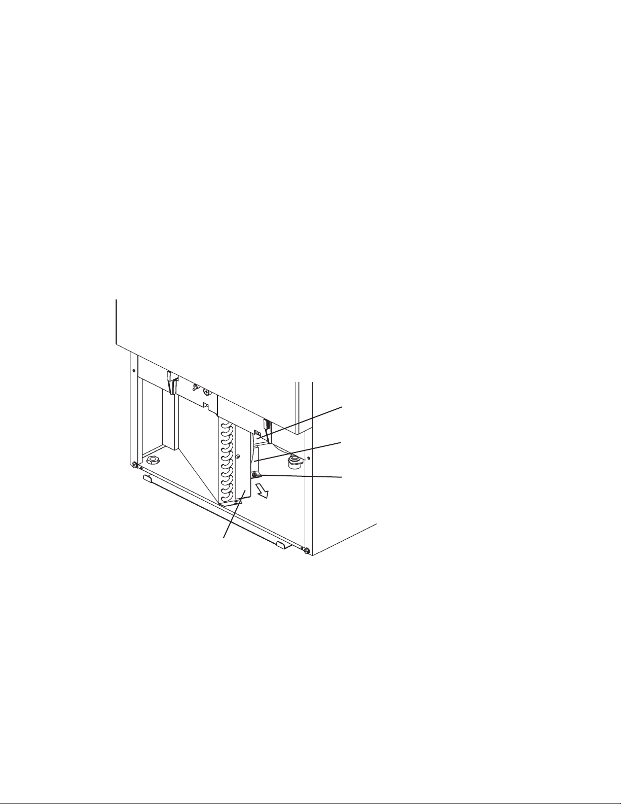
10. FAN MOTOR
1) Unplug the icemaker or disconnect the power source.
2) Remove the Louver.
3) Disconnect the Connector of the Fan Motor lead.
4) Remove the two screws securing the Fan Motor Bracket and pull out the Fan Motor
in the arrow direction. To prevent deformation, do not hit the Fan on the Condenser
or other parts.
5) Install the new Fan Motor in the reverse order of the removal procedure.
6) Refi t the Louver in its correct position.
7) Plug in the icemaker or connect the power source.
Condenser
Fan Motor
Fan Motor Bracket
Screw
Fig. 9
54
Page 60

11. PUMP MOTOR
1) Unplug the icemaker or disconnect the power source.
2) Remove the Top Panel and unscrew the Rear Panel.
3) Disconnect the Connector of the Pump Motor lead.
4) Remove the Water Tank (see “19. WATER TANK”).
5) Remove the ties connecting the Pump Motor discharge outlet and pull off the
Silicone Hose. Do not lose the Orifi ce coming off with the Hose.
Orifi ce
Silicone Hose
Tie
Fig. 10
6) Remove the screw securing the Pump Motor. Shift the Case to the center to release
it from the Stopper, and lift off the Pump Motor.
Lift off
Screw
Stopper
Slide to center
Fig. 11
7) Install the new motor in the reverse order of the removal procedure.
8) Plug in the icemaker or connect the power source, and check for leaks.
9) Refi t the panels in their correct positions.
55
Page 61

12. WATER VALVE
1) Unplug the icemaker or disconnect the power source.
2) Close the water supply tap.
3) Remove the Top Panel and unscrew the Rear Panel.
4) Disconnect the Tab Terminals.
5) Pinch and lower the Hose Clamp.
6) Disconnect the Rubber Hose from the Water Valve. Put a towel under the Water
Valve to receive water coming out.
7) Turn the Inlet Nut in the arrow direction to remove it from the Water Valve. Do not
lose the Gasket inside.
8) Remove the two mounting screws.
9) Install the new valve in the reverse order of the removal procedure.
10) Tighten the Inlet Nut to a torque of 70 in•lbs (±5%) to prevent water leaks.
11) Open the water supply tap.
12) Plug in the icemaker or connect the power source.
13) Check for leaks.
14) Refi t the panels in their correct positions.
Tab Terminal
Hose Clamp
Mounting Screw
Inlet Nut
Fig. 12
56
Rubber Hose
Page 62

13. CLEANING VALVE
1) Unplug the icemaker or disconnect the power source.
2) Remove the Top Panel and unscrew the Rear Panel.
3) Disconnect the Connectors (or Tab Terminals) of the Cleaning Valve lead.
4) Pinch and shift the two Hose Clamps.
5) Disconnect the Hoses from the Cleaning Valve. Put a towel under the Cleaning
Valve to receive any water coming out and prevent it from splashing out.
6) Remove the mounting screw.
7) Install the new valve in the reverse order of the removal procedure.
8) Plug in the icemaker or connect the power source.
9) Check for leaks.
10) Refi t the panels in their correct positions.
Mounting Screw
Hose
Hose Clamp
Fig. 13
Hose
57
Page 63

14. DRAIN VALVE
1) Unplug the icemaker or disconnect the power source.
2) Close the water supply tap.
3) Drain the Water Tank (see “19. WATER TANK”).
4) Disconnect any rigid (fi xed) pipe for water supply and drain connections.
5) Unscrew the Rear Cover. Pull out the unit for easy access to the Drain Valve.
6) Disconnect the Connectors (or Tab Terminals) of the Drain Valve lead.
7) Pinch and shift the two Hose Clamps.
8) Disconnect the Hoses from the Drain Valve. Put a towel under the Drain Valve to
receive any water coming out and prevent it from splashing out.
9) Remove the two mounting screws.
10) Install the new valve in the reverse order of the removal procedure.
11) Reconnect the water supply and drain connections, if disconnected in step 4).
12) Open the water supply tap.
13) Plug in the icemaker or connect the power source.
14) Check for leaks.
15) Refi t the panels in their correct positions.
Mounting Screw
Fig. 14
Hose Clamp
* Pinch and shift to left
58
Hose Clamp
* Pinch and lower
Page 64

15. FLOAT SWITCH
[a] KM-61BAH, KM-101BAH
1) Unplug the icemaker or disconnect the power source.
2) Remove the Top Panel and unscrew the Rear Panel.
3) Disconnect the Connector of the Float Switch lead and remove the lead wire from
the grommet opening.
4) Remove the Water Tank (see “19. WATER TANK”).
5) Remove the screw securing the Float Switch.
6) Install the new Float Switch in the reverse order of the removal procedure.
7) Refi t the panels in their correct positions.
8) Plug in the icemaker or connect the power source.
Grommet
Opening
Mounting Screw
Fig. 15
Float Switch
* Attach to three arrowed
surfaces when fi xing
with screw
59
Page 65

[b] KM-151BAH, KM-151BWH
1) Unplug the icemaker or disconnect the power source.
2) Remove the Top Panel and unscrew the Rear Panel.
3) Disconnect the Connector of the Float Switch lead (gray).
4) The Float Switch is located behind the Pump Motor. Pinch where indicated (1) and
pull it forward diagonally (2) to unhook the Float Switch.
Pull
Pinch
Pump Motor
Hook (B)
Float Switch
Screw
Hook (A)
Bracket
Float Switch
Fig. 16
5) Remove the screw securing the Float Switch to the Bracket.
6) Attach the new Float Switch to the Rail of the Bracket. Secure them with the screw
by fi tting the round end of the slot to the screw hole.
Rail
When fi tted properly, top ends
of Bracket and Float Switch
become fl ush with each other
Round end of slot
* Secure here with
screw
Screw
Fig. 17
60
Page 66

7) Put the Float Switch down into the mounting hole and hook it in position as shown.
To ensure proper operation, be sure to fi t the Hook (A) under the mounting hole.
8) Refi t the removed parts in the reverse order of the removal procedure.
9) Plug in the icemaker or connect the power source.
Mounting Hole
Fig. 18
16. BIN CONTROL SWITCH
1) Unplug the icemaker or disconnect the power source.
2) Remove the Top Panel and unscrew the Rear Panel.
3) Disconnect the Connector of the Bin Control Switch lead (black) covered with a
silicone hose and remove the lead wire from the Grommet.
4) Remove the Water Tank (see “19. WATER TANK”). The Bin Control Switch is located
as shown below when viewed from the front.
Separator Bin Control Switch
Fig. 19
5) Pull down and remove the lead wire from the retainer on the right side of the Bin
Control Switch.
6) Hold both sides of the Bin Control Switch and pull it toward you.
61
Page 67

Evaporator
Retainer
Pump Motor
Hold here and pull toward you
Slide Rail
[both sides]
Pull
Fig. 20
Stopper (A) [both sides]
7) The Bin Control Switch (KM-61BAH) pulled out of the Storage Bin has the internal
structure as shown below.
Reed Switch Lead Hook
Stopper (B) [both sides]
* Fit in Stopper (A)
Bin Switch Case Bin Switch Plate Reed Switch Cover
Fig. 21
62
Page 68

8) To remove the Bin Switch Plate, slightly fl ex both sides and pull the Shaft toward
you.
Slightly fl ex
Top View
Pull toward you
Fig. 22
9) Refi t the removed parts in the reverse order of the removal procedure. Be sure to
put the lead wire back in the Retainer on the Bracket.
10) Plug in the icemaker or connect the power source.
63
Page 69

17. THERMISTOR
1) Unplug the icemaker or disconnect the power source.
2) Remove the Top Panel and unscrew the Rear Panel.
3) Disconnect the Connector of the Thermistor lead (orange).
4) Remove the Ties, Insulation, Thermistor Holder, and Thermistor in this order.
5) Remove the old sealant from the Thermistor Holder and Suction Pipe.
6) Wipe off any moisture or condensation from the Suction Pipe surfaces.
7) Press a tube of the sealant KE4560RTV, manufactured by Shin-Etsu Silicones, to
the recess of the Thermistor Holder. Slowly squeeze the sealant out of the tube and
spread it smoothly in the recess. Do not use any sealant other than the above.
8) Attach the new Thermistor in position on the Suction Pipe and press down the
Thermistor Holder over the Thermistor. Be careful not to damage the Thermistor
lead. Cover the parts with the Insulation and secure them with the Ties. Keep the
Thermistor inside the Thermistor Holder. After the Thermistor Holder is fi tted, do not
pull the Thermistor lead to move the Thermistor.
9) Refi t the removed parts in the reverse order of the removal procedure.
10) Plug in the icemaker or connect the power source.
Thermistor Lead Tie
After Thermistor Holder is fi tted,
do not pull Thermistor lead
Insulation Thermistor Holder
Fill in shaded area
Fit right on top of pipe
Fill up to slightly above top of recess
Do not let in air and
make a hollow in recess
Fig. 23
64
Page 70

18. CONTROL BOX
1) Unplug the icemaker or disconnect the power source.
2) Remove the Louver.
3) Tilt the Tabs inward at the same time on both sides of the Control Box and pull the
Control Box toward you. Tilting only one Tab will not work.
4) To refi t the Control Box, push it in horizontally.
Note: After replacing the components inside the Control Box, connect and tie the wires
properly in their correct position. Especially make sure that the Harness does not
press the Push Buttons on the Control Board.
Control Box
Transformer
Capacitor
(KM-101/151 only)
Positioning Lug
Fig. 24
Ta b
Control Box
Power Relay
Fuse
Fuse Holder
Power Switch
Push Button
Control Board
Ta b
65
Page 71

[a] POWER SWITCH
1) Disconnect the Tab Terminals and remove the Nut securing the Power Switch.
2) Install the new Switch in the reverse order of the removal procedure.
3) To prevent miswiring, check the terminal numbers and lead wire colors with the
Wiring Label.
[b] FUSE
1) Use a phillips head screwdriver to remove the Fuse Holder Cap and take out the
Fuse.
2) Install the new Fuse in the reverse order of the removal procedure.
[c] FUSE HOLDER
1) Disconnect the Tab Terminal and remove the Nut securing the Fuse Holder.
2) Install the new Fuse Holder in the reverse order of the removal procedure.
[d] CONTROL BOARD
1) Disconnect all the Connectors.
2) Pull the Tab to release the Control Board.
3) Lift off the Control Board.
4) To refi t the Control Board, fi t its four corner holes on the positioning lugs inside the
Control Box and secure the Control Board with the Tab.
5) When reconnecting the Connectors, do not push them too hard. The Control Board
may be damaged.
[e] POWER RELAY
1) Disconnect the Tab Terminals, remove the mounting screw, and lift off the Power
Relay from the fi t at the bottom.
2) Install the new Relay in the reverse order of the removal procedure.
66
Page 72

3) To prevent miswiring, check the terminal numbers and lead wire colors with the
Wiring Label.
[f] COMPRESSOR CAPACITOR - EXCEPT KM-61BAH
1) Disconnect the Tab Terminals and cut the Tie.
2) Install the new Capacitor in the reverse order of the removal procedure. Use a cable
tie to secure the Capacitor tightly.
[g] CONTROL BOARD TRANSFORMER
1) Disconnect the Connectors and Closed End Connectors connecting the Control
Board. (The Tie securing the harness may be removed. But be careful not to break
the lead wires.)
2) Remove the mounting screw and lift off the Transformer from the fi t at the bottom.
3) Install the new Transformer in the reverse order of the removal procedure.
19. WATER TANK
1) Unplug the icemaker or disconnect the power source. Remove all ice from the
Storage Bin.
2) Drain out the Water Tank by pulling off the Overflow Pipe from the Water Tank
bottom and the Silicone Hose from the Storage Bin bottom.
Cube Guide
Silicone Hose
(Connect/disconnect
arrowed part)
Storage Bin
Water Tank
Overfl ow Pipe
(Disconnect from tank
bottom)
Fig. 25
67
Page 73

3) Pinch and push down the Snaps on
both sides of the Bracket to unhook
the Water Tank from the square holes,
and pull it about 1” toward you.
4) When the Snaps are unhooked from
the square holes, the rear part of the
Water Tank (dotted circle below) is also
unhooked. Hold the Water Tank with
both hands.
Pinch
Snap
Pull
Water Tank
Fig. 26
5) Tilt the right side of the Water Tank and
pull it toward you. Do not hit the Pump
Motor or Float Switch. Slightly twist the
left side of the Water Tank inward and
pull it toward you.
Pump Motor
Float Switch
Fig. 27
Left Side
Right Side
Fig. 28
68
Page 74

6) Slide the left side of the Water Tank to
release it from the Bracket Rail, lift down
the entire Water Tank, and pull it toward
you out of the Storage Bin. Do not hit the
other components.
7) Refi t the Water Tank in the reverse order
Bracket Rail
of the removal procedure (left, right, top,
rear).
8) Plug in the icemaker or connect the
power source.
Fig. 29
20. CUBE GUIDE
1) Remove the Water Tank (see “19. WATER TANK”).
2) Lift off the Cube Guide out of the Water Tank.
3) To refi t the Cube Guide, fi t the Notches on both sides to the Stoppers in the Water
Tank.
4) The unit is provided with two or three Cube Guides (quantity varies depending on
model). Be sure to locate the Vertical Flanges on the outside edges.
Vertical Flange Notch
Cube Guide
Stopper
Fig. 30
69
Page 75

21. SEPARATOR
1) Unplug the icemaker or disconnect the power source.
2) Remove the screws at the rear and take off the Top Panel.
3) Hold both sides of the Separator from the top. Bend the Front Separator into a
U-shape and remove it from the Shaft of the Evaporator Bracket. Bend the Rear
Separator into an inverted U-shape and lift it off the Shaft of the Evaporator Bracket.
4) Refi t the Separator in the reverse order of the removal procedure. Check that the
Separator is fi t correctly on the Shaft and can swing like a pendulum.
5) Plug in the icemaker or connect the power source.
Spray Tube
Spray Guide
Front Separator
Evaporator Bracket
Rear Separator
Water Supply Tube
Fig. 31
22. SPRAY TUBE, WATER SUPPLY PIPE, SPRAY GUIDE
1) Unplug the icemaker or disconnect the power source. Remove the Top Panel.
2) Push the Tabs on both sides to release the Spray Tube.
3) Remove the end of the Spray Tube from the Bracket.
4) Pinch and lower the Hose Clamp and disconnect the Hose. The Spray Tube is easily
cleanable by removing the black rubber cap on the end.
70
Page 76

5) The Water Supply Pipe is located right under the Spray Tube. Remove the Water
Supply Pipe from the Evaporator, pinch and shift the Hose Clamp, and disconnect
the Hose.
6) The Spray Guide is located under the Water Supply Pipe. Pull off the Spray Guide
from the Evaporator Plate.
7) Refi t the removed parts in the reverse order of the removal procedure. Check for
water leaks.
IMPORTANT
Fit the Spray Guide securely and tightly on the Evaporator fi n. Otherwise,
cloudy or irregular ice cubes or performance reduction may be caused.
8) Plug in the icemaker or connect the power source.
23. DOOR
1) Remove the Top Panel.
2) Move the Door to fi t the Door Shaft in the inlet of the Door Channel. Slide up the
Door to release it from the Door Channel.
3) Refi t the Door in the reverse order of the removal procedure. Do not forget to fi t the
Collar on the Door Shaft, or the Door will not open or close smoothly.
Door Channel
Fig. 32
71
Page 77

VI. CLEANING AND MAINTENANCE INSTRUCTIONS
IMPORTANT
Ensure all components, fasteners and screws are securely in place after
any maintenance or cleaning is done to the equipment.
1. CLEANING
WARNING
1. Hoshizaki recommends cleaning this unit at least once a year. More
frequent cleaning, however, may be required in some existing water
conditions.
2. To prevent injury to individuals and damage to the icemaker, do not use
ammonia type cleaners.
3. Always wear liquid-proof gloves to prevent the cleaning and sanitizing
solutions from coming into contact with skin.
4. For safety and maximum effectiveness, use cleaning and sanitizing
solutions immediately after dilution.
[a] CLEANING PROCEDURE
1) Dilute 5 fl . oz. (148 ml) of recommended cleaner Hoshizaki “Scale Away” or “LIME-
A-WAY” (Economics Laboratory, Inc.) with 1 gallon (3.8 lit.) of water.
2) Remove the Air Filter. Remove all ice from the Evaporator and the Storage Bin.
Note: To remove cubes on the Evaporator, move the Control Switch on the Control
Box to the “OFF” position and move it back to the “ICE” position after 3
minutes. The defrost cycle starts and the cubes will be removed from the
Evaporator.
3) Move the Control Switch to the “OFF” position. Open the Door.
4) Disconnect the Silicone Hose to drain the water. See Fig. 25. Reconnect the Silicone
Hose back in its correct position after all of the water has drained.
5) Pour the cleaning solution into the Water Tank. Move the Control Switch to the
“WASH” position. Close the Door.
72
Page 78
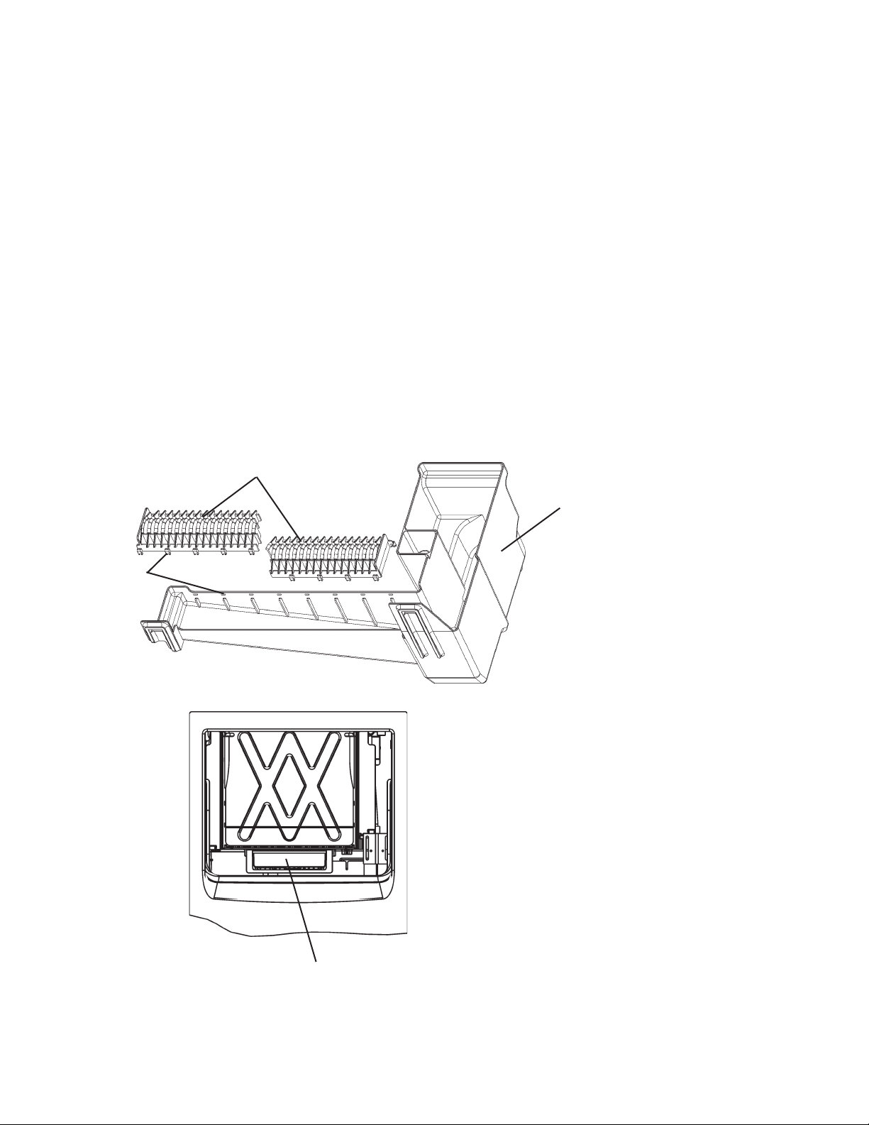
6) After 30 minutes, move the Control Switch to the “OFF” position.
7) Same as step 4.
8) Move the Control Switch to the “ICE” position to fi ll the Water Tank with water.
9) After 3 minutes, move the Control Switch to the “WASH” position.
10) After 5 minutes, move the Control Switch to the “OFF” position.
11) Same as step 4.
12) Repeat steps 8 through 11 three more times to rinse thoroughly.
13) Disconnect the Silicone Hose and Overfl ow Pipe. Remove the Water Tank. See “V.
19. WATER TANK” for details.
14) Pull the Cube Guides (quantity varies depending on model) upward to remove them
from the Water Tank. They are snapped in place. See Fig. 33. Refer to “V. 20. CUBE
GUIDE” for details.
Snap
Cube Guide
Water Tank
* This illustration shows KM-61BAH.
The following number of Cube
Guides are provided:
KM-61BAH 2 pcs
KM-101BAH 3 pcs
KM-151BAH 3 pcs
KM-151BWH 3 pcs
* The Bin Control Switch is accessible by
removing the Water Tank. Pull the switch
towards you for easy maintenance.
* This is the front view with the Door opened
and the Water Tank removed.
Bin Control Switch
Fig. 33
73
Page 79

15) Same as step 1.
16) Wash the Bin Control Switch, Water Tank, Float Switch, Cube Guide, Silicone Hose
and Overfl ow Pipe by using a nylon scouring pad, brushes and the cleaning solution.
In addition to the removed parts, also wash the bin liner and Bracket (L) (R) with the
solution.
17) Discard the cleaning solution and rinse the parts thoroughly with water.
[b] SANITIZING PROCEDURE - Following Cleaning Procedure
1) Dilute approximately 0.5 fl. oz. (15 ml or 1 tbs) of a 5.25% sodium hypochlorite
solution (chlorine bleach) with 1 gallon (3.8 lit.) of warm water. Using a chlorine test
strip or other method, confi rm that you have a concentration of about 200 ppm.
2) Soak the removed parts from step 16 above in a clean container containing the
sanitizing solution. After allowing the parts to soak for 10 minutes, wash them with
the solution. Also wash the bin liner, Bracket (L) (R) with the solution.
3) Discard the sanitizing solution and rinse the parts thoroughly with water.
4) Replace the removed parts in their correct positions in the reverse order of which
they were removed.
5) Same as step 1.
6) Pour the sanitizing solution into the Water Tank, and allow the sanitizer to sit for 10
minutes.
7) Move the Control Switch to the “WASH” position. Close the Door.
8) After 15 minutes, move the Control Switch to the “OFF” position. Open the Door.
9) Disconnect the Silicone Hose to drain the water. Reconnect the Silicone Hose back
in its correct position after all of the water has drained.
10) Repeat steps 5 through 9 one time. Repeat steps 8 through 11 in the Cleaning
Procedure three times to rinse thoroughly.
11) Flush the Storage Bin with water.
12) Move the Control Switch to the “ICE” position, and start the automatic icemaking
process.
13) Close the Door. Replace the Air Filter in its correct position.
74
Page 80

2. MAINTENANCE
[a] EXTERIOR PANELS
To prevent corrosion, wipe the exterior occasionally with a clean and soft cloth. Use a
damp cloth containing a neutral cleaner to wipe off all oil or dirt build up.
[b] STORAGE BIN AND SCOOP
* Wash your hands before removing ice. Use the plastic scoop provided (Accessory).
* The Storage Bin is for ice use only. Do not store anything else in the bin.
* Keep the scoop clean. Clean it by using a neutral cleaner and rinse thoroughly.
* Clean the bin liner by using a neutral cleaner. Rinse thoroughly after cleaning.
[c] AIR FILTER
The plastic mesh Air Filter removes dirt or dust from the air, and keeps the Condenser
from getting clogged. As the filter gets clogged, the icemaker’s performance will be
reduced. Check the fi lter at least twice a month. When it is clogged, use warm water
and a neutral cleaner to wash the fi lter.
[d] CONDENSER
Check the Condenser once a year, and clean if required by using a brush or vacuum
cleaner. More frequent cleaning may be required depending on the location of the
icemaker.
75
Page 81

3. PREPARING THE ICEMAKER FOR LONG STORAGE
IMPORTANT
When shutting off the icemaker for an extended time, drain out all water
from the water lines and remove the ice from the Storage Bin. The Storage
Bin should be cleaned and dried. Drain the icemaker using air or carbon
dioxide to prevent damage to the water supply lines at sub-freezing
temperatures. Shut off the icemaker until the proper ambient temperature is
resumed.
When the icemaker is not used for two or three days, it is sufficient to only move
the Control Switch to the “OFF” position, unless the icemaker will be at sub-freezing
temperatures.
[a] On KM-151BWH only, fi rst remove the water from the Water-cooled Condenser:
1) Remove the Air Filter if it has not already been removed.
2) Move the Control Switch on the Control Box to the “OFF” position.
3) Wait 3 minutes.
4) Move the Control Switch to the “ICE” position.
5) Allow 5 minutes for the icemaker to fill with water and the Water Pump to start
operating.
6) Close the Water-cooled Condenser water supply line Shut-off Valve.
7) Open the Drain Valve for the Water-cooled Condenser water supply line.
8) Allow the line to drain by gravity.
9) Attach compressed air or carbon dioxide supply to the Condenser water line Drain
Valve.
10) Blow the Water-cooled Condenser out, using compressed air or carbon dioxide until
water stops coming out.
[b] Remove the water from the potable water supply line:
1) Remove the Air Filter if it has not already been removed.
2) Move the Control Switch on the Control Box to the “OFF” position.
76
Page 82

3) Wait 3 minutes.
4) Close the potable water supply line Shut-off Valve and open the potable water
supply line Drain Valve. See Fig. 34.
5) Allow the line to drain by gravity.
6) Attach compressed air or carbon dioxide supply to the potable water supply line
Drain Valve.
7) Move the Control Switch to the “ICE” position.
8) Quickly blow the potable water supply line out using compressed air or carbon
dioxide.
[c] Drain the potable Water Tank:
1) Turn off the power supply at the breaker box.
2) Move the Control Switch on the Control Box to the “OFF” position.
3) Open the Door. Disconnect the Silicone Hose to drain the water. See Fig. 25.
4) Reconnect the Silicone Hose back in its correct position after all of the water has
drained.
5) Remove all ice from the Storage Bin and clean the Storage Bin.
6) Close the Door.
7) Place the Air Filter in its correct position.
8) Close the potable water supply line Drain Valve.
77
Page 83

KM-61BAH, KM-101BAH, KM-151BAH
Drain Outlet
3/4” FPT
Fig. 34
Water Supply Inlet
1/2” FPT
78
Page 84

KM-151BWH
Bin Drain Outlet
3/4” FPT
Separate piping to approved drain.
Leave a two-inch (5 cm) vertical air
gap between the end of each pipe
and the drain.
Two-inch (5 cm)
air gap
Floor
Drain
Condenser Water
Outlet 1/2” FPT
Drain Valve
Condenser Water
Inlet 1/2” FPT
Icemaking Water Supply
Inlet 1/2” FPT
Shut-off Valve
Drain Valve
Shut-off Valve
Fig. 35
79
 Loading...