

Page 1
Parts List
Modular Crescent Cuber
Models
KM-515MAJ, MWJ, MRJ
hoshizakiamerica.com
Number: 71390
Issued: 10-23-2017
Revised: 11-17-2017
Page 2

CONTENTS
Auxiliary Codes ...................................................................................................................... 3
Note About Ordering Parts .................................................................................................... 3
A. Main Assembly & Refrigeration Circuit ............................................................................. 4
KM-515MAJ ...................................................................................................................... 4
KM-515MWJ ...................................................................................................................... 6
KM-515MRJ ...................................................................................................................... 8
B. Water Circuit .................................................................................................................... 10
C. Control Box Assembly ..................................................................................................... 13
D. Accessories & Labels ...................................................................................................... 15
2
Page 3

Auxiliary Codes
KM-515MAJ
G-1 October 2017
KM-515MWJ
G-1 October 2017
KM-515MRJ
G-1 October 2017
Auxiliary Code Breakdown
The auxiliary code is the rst two characters in the serial number. The rst character
indicates the year. Years progress or regress in alphabetical order. The series runs from
"A" through "V" and the letters "I" and "O" are skipped. The second character indicates
signicant part changes within a year. Base is "0" and this number advances for each
change. In cases where there is a letter in parentheses, this designates the month. This is
the last character in the serial number. The series runs from "(A)" through "(M)" and the
letter "(I)" is skipped. This designation is only included when identifying a parts change
within an auxiliary code.
Note About Ordering Parts
Most assemblies cannot be ordered as complete units; parts in the assemblies generally
must be ordered separately.
3
Page 4
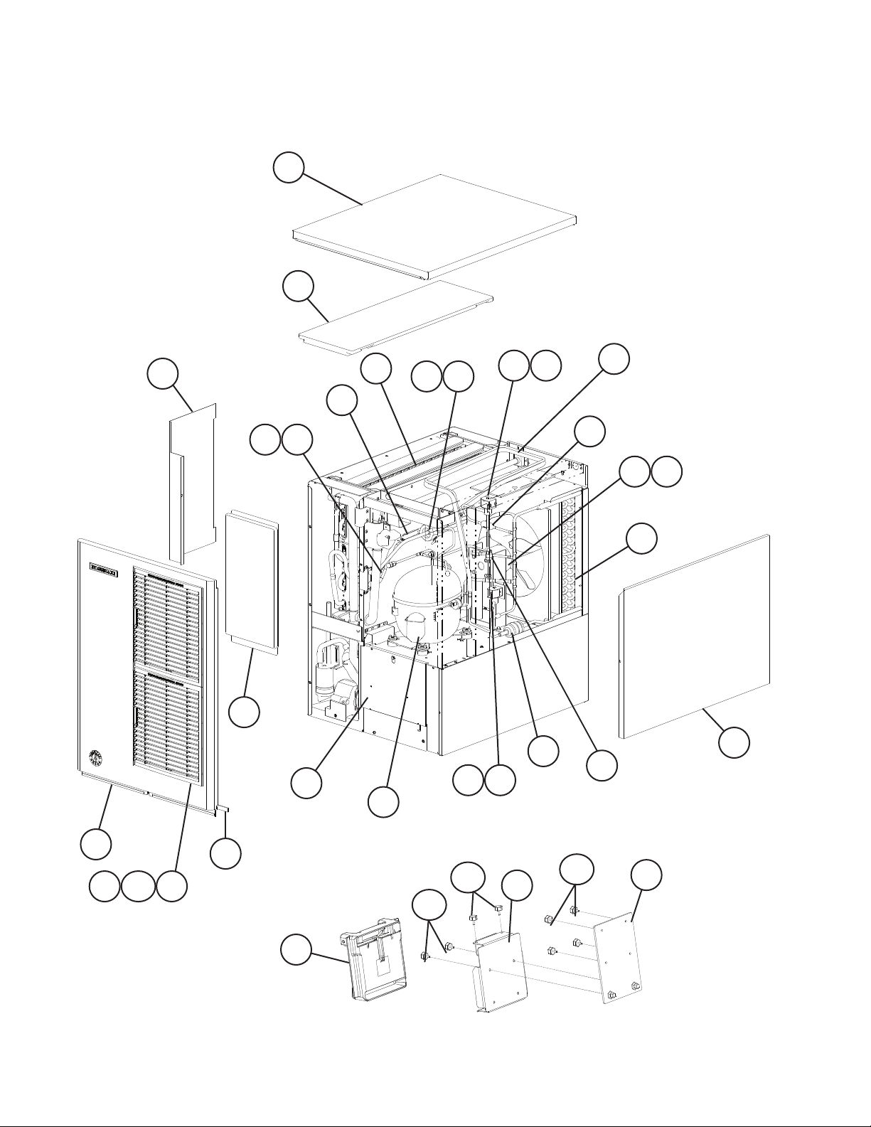
A. Main Assembly & Refrigeration Circuit
KM-515MAJ
G-1
6
7
10
24 25
3
16
19
9
14
17 18
21 22
20 22
29
30
28
26 27
15
8
23
1
4 4a
2
5
12
12a
11a
4
11
13a
13
Page 5
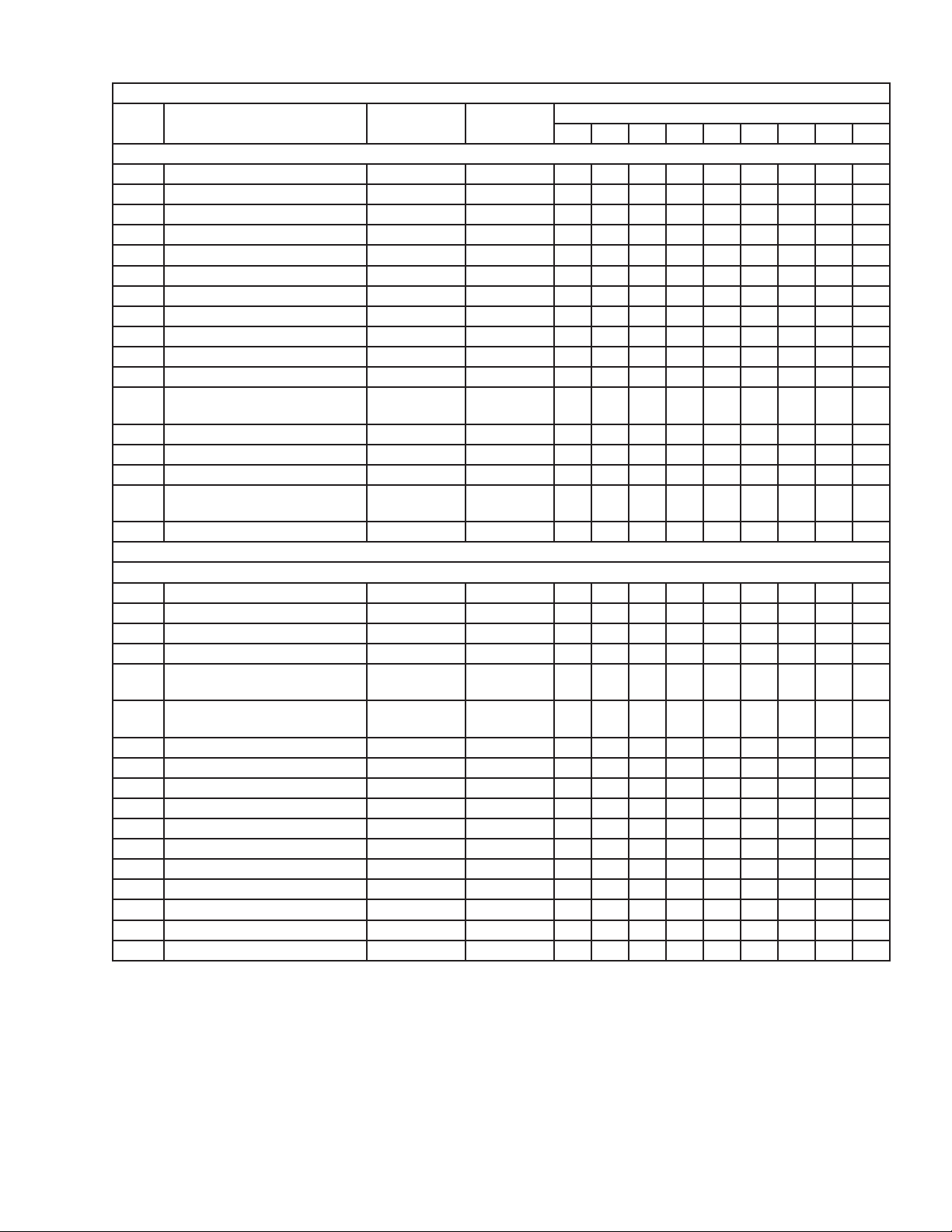
Title: A. Main Assembly & Refrigeration Circuit Model: KM-515MAJ
Index
No. Description
1 Front Panel 2A3767G01 1
2 Gasket L=554 mm 4A0808L02 1
3 Front Insulation 215731G01 1
4 Louver 1A0547-01 2
4a Push Retainer 4A2414-01 6
5 Air Filter 2A2062G01 2
6 Top Panel 3A3878A01 1
7 Top Insulation 215730G01 1
8 Right Side Panel 2A2117G01 1
9 Base Cover 321525G01 1
10 Control Box Cover 3A2476-01 1
11 Mechanical Bin Control Switch
Mount
11a Thumbscrew 415949G10 2
12 Mechanical Bin Control 2A4393G02 1
12a Thumbscrew 415949G10 2
13 Mechanical Bin Control
Extension Bracket
13a Thumbscrew 415949G10 4
Material or
Model Number Part Number
Main Assembly
3A6040-01 1
4A5046G01 1
G-1
Required Number
Refrigeration Circuit
14 Compressor 4A4479-01 1
15 Condenser 2A3756-01 1
16 Evaporator 1A4051G01 1
17 Thermostatic Expansion Valve 4A4008-01 1
18 Thermostatic Expansion Valve
Cover
19 Thermostatic Expansion Valve
Bulb Holder
20 Hot Gas Valve Body 4A3978-01 1
21 Liquid Line Valve Body 4A3276-01 1
22 Valve Coil 4A3277-01 2
23 High-Pressure Switch 463180-04 1
24 Thermistor 429006-03 1
25 Thermistor Holder 427430-01 1
26 Fan Motor 4A3158-01 1
27 Fan Blade 4A3959-01 1
28 Strainer 441569-01 1
29 Drier 4A1113-01 1
30 Heat Exchanger 2A4382G01 1
3A0944-01 1
3A0107-01 1
5
Page 6
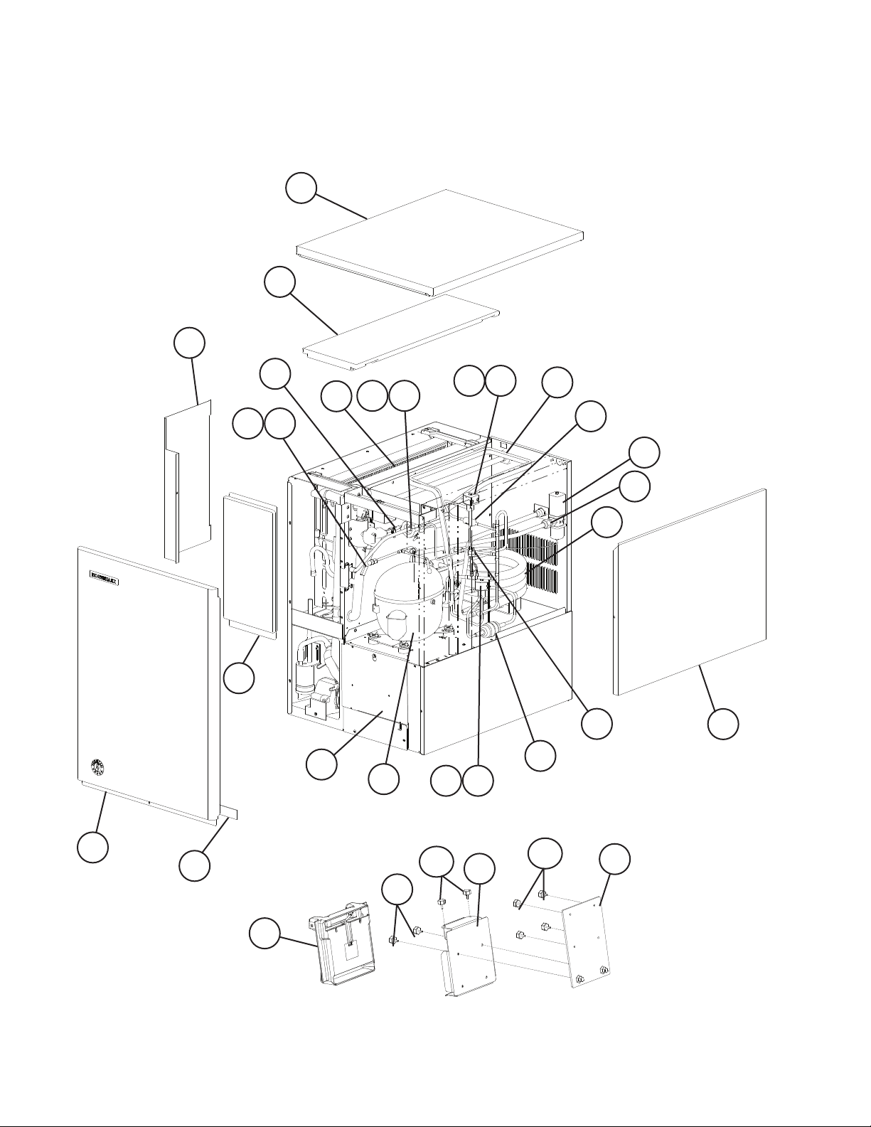
A. Main Assembly & Refrigeration Circuit
KM-515MWJ
G-1
4
5
8
19
24 25
3
20 22
17 18
16
7
12
21 22
27
28
26
23
14
15
13
6
1
2
10
9a
10a
6
9
11a
11
Page 7
Title: A. Main Assembly & Refrigeration Circuit Model: KM-515MWJ
Index
No. Description
1 Front Panel 2A2150G01 1
2 Gasket L=554 mm 4A0808L02 1
3 Front Insulation 215731G01 1
4 Top Panel 3A3878A01 1
5 Top Insulation 215730G01 1
6 Right Side Panel 2A2117G01 1
7 Base Cover 321525G01 1
8 Control Box Cover 3A2476-01 1
9 Mechanical Bin Control Switch
Mount
9a Thumbscrew 415949G10 2
10 Mechanical Bin Control 2A4393G02 1
10a Thumbscrew 415949G10 2
11 Mechanical Bin Control
Extension Bracket
11a Thumbscrew 415949G10 4
12 Compressor 4A4479-01 1
13 Condenser 3A7321-01 1
14 Water Regulating Valve 4A0911-06 1
15 Male Connector 4A1087-01 1
16 Evaporator 1A4051G01 1
17 Thermostatic Expansion Valve 4A4008-01 1
18 Thermostatic Expansion Valve
Cover
19 Thermostatic Expansion Valve
Bulb Holder
20 Hot Gas Valve Body 4A3978-01 1
21 Liquid Line Valve Body 4A3276-01 1
22 Valve Coil 4A3277-01 2
23 High-Pressure Switch 463180-05 1
24 Thermistor 429006-03 1
25 Thermistor Holder 427430-01 1
26 Strainer 441569-01 1
27 Drier 4A1113-01 1
28 Heat Exchanger 2A4382G01 1
Material or
Model Number Part Number
Main Assembly
3A6040-01 1
4A5046G01 1
Refrigeration Circuit
3A0944-01 1
3A0107-01 1
G-1
Required Number
7
Page 8

A. Main Assembly & Refrigeration Circuit
KM-515MRJ
G-1
4
5
8
19
24 25
3
16
17 18
7
20 22
23
30
26
9
28
29
15
27
6
13
1
2
11
14
10a
21 22
11a
8
10
12a
12
Page 9

Title: A. Main Assembly & Refrigeration Circuit Model: KM-515MRJ
Index
No. Description
1 Front Panel 2A2150G01 1
2 Gasket L=554 mm 4A0808L02 1
3 Front Insulation 215731G01 1
4 Top Panel 3A3878A01 1
5 Top Insulation 215730G01 1
6 Right Side Panel 2A2117G01 1
7 Base Cover 321525G01 1
8 Control Box Cover 3A2476-01 1
9 Junction Box Cover 433410-01 1
10 Mechanical Bin Control Switch
Mount
10a Thumbscrew 415949G10 2
11 Mechanical Bin Control 2A4393G02 1
11a Thumbscrew 415949G10 2
12 Mechanical Bin Control
Extension Bracket
12a Thumbscrew 415949G10 4
13 Compressor 4A4479-01 1
14 Crankcase Heater 4A5091-01 1
15 Receiver Tank 437596-01 1
16 Evaporator 1A4051G01 1
17 Thermostatic Expansion Valve 4A1414-01 1
18 Thermostatic Expansion Valve
Cover
19 Thermostatic Expansion Valve
Bulb Holder
20 Hot Gas Valve Body 4A3978-01 1
21 Liquid Line Valve Body 4A3276-01 1
22 Valve Coil 4A3277-01 2
23 High-Pressure Switch 463180-04 1
24 Thermistor 429006-03 1
25 Thermistor Holder 427430-01 1
26 Strainer 441569-01 1
27 Drier 4A1113-01 1
28 Liquid Line Coupling 426554-01 1
29 Discharge Line Coupling 434072-01 1
30 Heat Exchanger 2A4382G01 1
Material or
Model Number Part Number
Ice Cuber Assembly
3A6040-01 1
4A5046G01 1
Refrigeration Circuit
3A0944-01 1
3A0107-01 1
G-1
Required Number
9
Page 10

B. Water Circuit
KM-515M_J
G-1
12
17
14
13
24
23
21
22
44
39
38
27
16
40
28
25
26
42
37
35
11
41
15
29
30
31
9
10
33
18
32
34
19
19c
19a
19b
20
43
36
8
Pump Motor Assembly
3
1
2
10
5
4
6
7 7a
Page 11
Title: B. Water Circuit Model: KM-515M_J
Index
No. Description
1 Pump Motor Assembly
(includes pump motor and
items 2 through 7a)
2 Pump Flange 3A2988-01 1
3 Mechanical Seal 465627-01 1
4 Impeller 433522-01 1
5 Pin 4A0648-01 1
6 Pump Gasket 4A2974-01 1
7 Pump Housing 211409-01 1
7a Screw 4×20 4A3871-01 4
8 Pump Motor Bracket 211408-01 1
9 Water Supply Pipe 4A5216G04 1
10 Rubber Gasket 413854-03 1
11 Inlet Water Valve 3U0111-03 1
12 Spray Tube 1A0260-02 1
13 Spray Guide 2A4282-02 2
14 Water Supply Tube 2A0079-01 1
15 Distributor (Tee) 4A0177-01 1
16 Flange 439267-01 1
17 Spray Tube Plug 4A0176-01 2
18 Cube Guide 212088-01 1
19 Splash Curtain 3A9602-01 1
19a Thumbscrew 415949G10 1
19b Collar 435269-01 1
19c Screw 4×12 7C22-0412 1
20 Separator 4X7933-01 12
21 Float Switch 4A3624-01 1
22 Float Switch Connector 426799-01 1
23 Silicone Hose L=140 mm 7730I3896 1
24 Silicone Hose (vent) L=140 mm 7730I3812 1
25 Drain Valve Housing 321001-01 1
26 Drain Valve Seat 433705-01 1
27 Drain Valve Spring 322110-01 1
28 Drain Valve O-Ring 7611-G035 1
29 Overow Cap 321002-01 1
30 Overow Pipe 430722-11 1
31 Overow Pipe O-Ring 4A1234-01 1
32 Cleaning Valve Handle 215383-01 1
33 Cleaning Valve Microswitch 4A2546-01 1
34 Cleaning Valve Ball Valve 439293-01 1
35 Cleaning Valve Male Adaptor 325826-01 2
36 Suction Hose 433466-01 1
37 Drain Hose 433468-01 1
38 Rubber Hose C 4A1551-03 1
39 Distributor (Tee) 432426-01 1
40 Rubber Ring 439236-01 1
41 Rubber Hose D 4A1551-04 1
42 Vinyl Hose L=250 mm 7716-2025 1
43 Vinyl Hose (drain) L=110 mm 7716-2025 1
44 Reducing Pipe 4A5767-01 1
Material or
Model Number Part Number
PA0613 3A2638A03 1
Required Number
G-1
11
Page 12

Title: B. Water Circuit Model: KM-515M_J
Index
No. Description
Hose Clamp 25 mm 427443-03 8
Hose Clamp 26 - 30 mm 4A2017-02 1
Hose Clamp 17 - 21.5 mm 4A2017-05 1
Material or
Model Number Part Number
Required Number
G-1
Hose Clamps
12
Page 13

C. Control Box Assembly
KM-515M_J
G-1
3
12
X13
8
4
9 10
7
7a
5
12
11
X12
X11
X10
6
1
2
13
Page 14

Title: C. Control Box Assembly Model: KM-515M_J
Index
No. Description
1 Start Capacitor 243-292MFD,
2 Run Capacitor 35MFD,
3 Start Relay 4A1107-11 1
4 Compressor Relay 4A3140-01 1
5 Pump Motor Capacitor 5.5MFD,
6 Control Transformer 3A0172-01 1
7 Control Board 2A7664-02 1
7a Control Board Support 4A0336-03 4
8 Toggle Switch (control) 443119-01 1
9 Fuse Holder 4A5443-01 1
10 Fuse AGC-10A,
11 Fan Motor Capacitor KM-515MAJ
12 Relay
(X10 - Pump Direction Relay
X11 - X10 Control Relay
X12 - Slush Control Relay)
Relay
(X13 - Crankcase Heater Relay)
Material or
Model Number Part Number
3A0076-20 1
165VAC
3A2005-12 1
440VAC
443192-03 1
250VAC
4A0893-07 1
250VAC
443192-02 1
5MFD,
250VAC
All Models 406132-07 3
KM-515MRJ 1
Required Number
G-1
14
Page 15
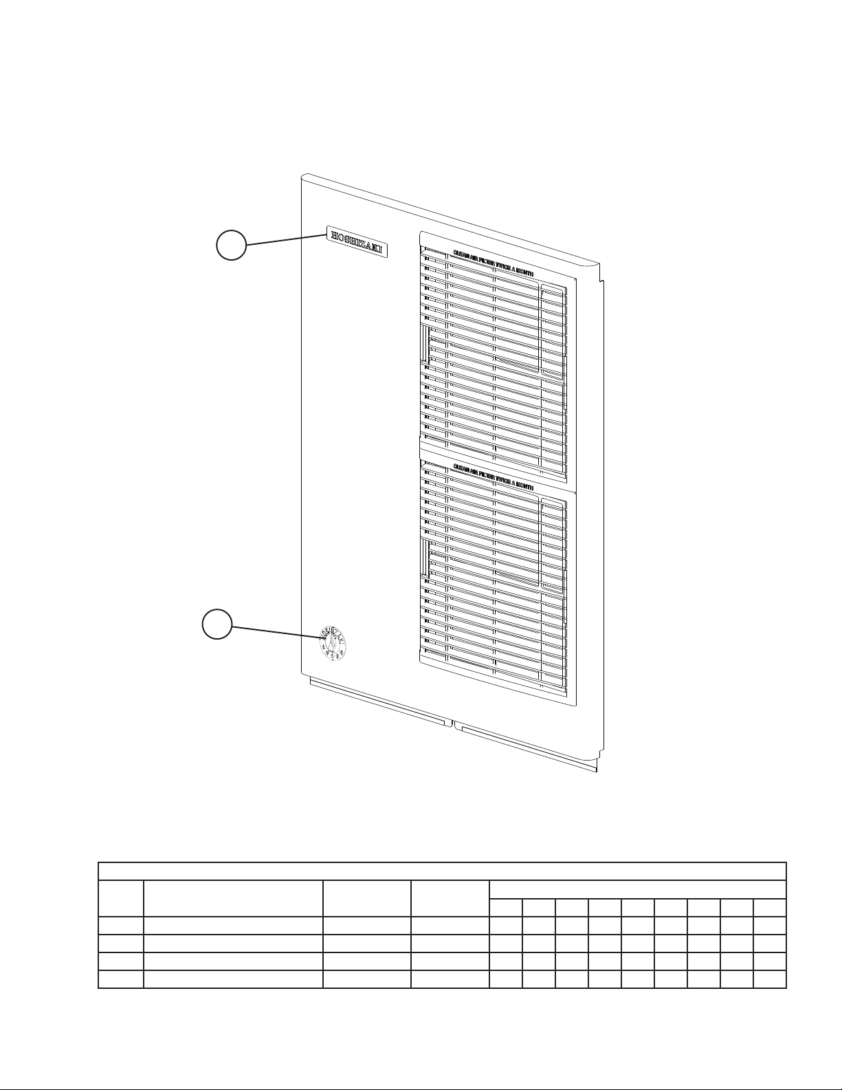
D. Accessories & Labels
KM-515M_J
G-1
1
2
Title: D. Accessories & Labels Model: KM-515M_J
Index
No. Description
1 Hoshizaki Emblem Label 4A0560-01 1
2 Penguin Label 475552L02 1
3 Universal Brace 4A0363-01 2
3a Hex Head Bolt 5×12, SS 7B02-0512 2
Material or
Model Number Part Number
Required Number
G-1
15
 Loading...