

Page 1

DISHWASHER
INSTALLATION MANUAL
JWE-620UA-6B
FOR QUALIFIED INSTALLER ONLY
9280VC10B (041111)
Page 2

IMPORTANT
Only qualified service technicians should install, service and maintain the
product. No installation, service or maintenance should be undertaken until
the technician has thoroughly read this Installation Manual. Likewise, the
owner/manager should not proceed to operate the product until the installer
has instructed them on its proper operation. Failure to install, operate, and
maintain the equipment in accordance with this manual may adversely affect
safety, performance, component life, and warranty coverage.
Hoshizaki provides this manual primarily to assist qualified service technicians in the
installation, maintenance, and service of the product.
Should the reader have any questions or concerns which have not been satisfactorily
addressed, please call, write, or send an e-mail message to the Hoshizaki Technical
Support Department for assistance.
HOSHIZAKI AMERICA, INC.
618 Highway 74 South
Peachtree City, GA 30269
Attn: Hoshizaki Technical Support Department
Phone: 1-800-233-1940 Technical Support
(770) 487-2331
Fax: 1-800-843-1056
(770) 487-3360
E-mail: techsupport@hoshizaki.com
Web Site: www.hoshizaki.com
NOTE: To expedite assistance, all correspondence/communication MUST include the
following information:
* Model Number
* Serial Number
* Complete and detailed explanation of the problem.
i
Page 3

IMPORTANT
This manual should be read carefully before the product is installed and
operated. Only qualified service technicians should install, service, and
maintain the product. Read the warnings contained in this booklet carefully as
they give important information regarding safety. Please retain this booklet for
any further reference that may be necessary.
CONTENTS
1. MOVING---------------------------------------------------------------------------------------------------1
2. INSTALLATION ------------------------------------------------------------------------------------------1
[a] SHIPPING TAPE ------------------------------------------------------------------------------------2
[b] CHECKS BEFORE INSTALLATION -----------------------------------------------------------3
[c] PROTECTIVE FILM --------------------------------------------------------------------------------3
[d] OPERATION PANEL -------------------------------------------------------------------------------3
[e] CONNECTION TO A DISHTABLE -------------------------------------------------------------4
[f] RACK GUIDE ----------------------------------------------------------------------------------------6
3. VENTILATION -------------------------------------------------------------------------------------------7
4. WATER SUPPLY AND DRAIN CONNECTIONS ------------------------------------------------7
[a] WATER HEATER CONNECTION --------------------------------------------------------------7
[b] PRESSURE REDUCING VALVE ---------------------------------------------------------------7
[c] WATER SOFTENER -------------------------------------------------------------------------------8
[d] STRAINER -------------------------------------------------------------------------------------------9
[e] HOT WATER SUPPLY CONNECTION -------------------------------------------------------9
[f] DRAIN CONNECTION (WASH TANK DRAIN)-------------------------------------------- 10
PAGE
5. ELECTRICAL CONNECTION --------------------------------------------------------------------- 10
6. PHASE REVERSAL CHECK ---------------------------------------------------------------------- 12
7. DETERGENT/RINSE AID FEEDER ------------------------------------------------------------- 13
8. TRIAL RUN --------------------------------------------------------------------------------------------- 14
[a] CHECKS BEFORE TRIAL RUN -------------------------------------------------------------- 14
[b] PREPARING HOT WATER SUPPLY -------------------------------------------------------- 15
[c] FINAL CHECKS ----------------------------------------------------------------------------------- 15
[d] AFTER TRIAL RUN ------------------------------------------------------------------------------ 16
[e] ADJUSTMENT ------------------------------------------------------------------------------------ 17
9. RELOCATION ----------------------------------------------------------------------------------------- 17
ii
Page 4

Important Safety Information
Throughout this manual, notices appear to bring your attention to situations which could
result in death, serious injury, or damage to the unit.
WARNING
CAUTION
Indicates a situation which could result in damage to the unit.
IMPORTANT
This product should be destined only to the use for which it has been
expressly conceived. Any other use should be considered improper and
therefore dangerous. The manufacturer cannot be held responsible for injury
or damage resulting from improper, incorrect, and unreasonable use.
To reduce the risk of death, electric shock, serious injury, or fi re, follow
basic precautions including the following:
• Electrical connection must be hard-wired and must meet national, state, and
local electrical code requirements. Failure to meet these code requirements
could result in death, electric shock, serious injury, fi re, or severe damage to
equipment.
• This unit requires independent power supplies for the dishwasher and for the
booster tank. See the nameplate for proper voltage and breaker/fuse sizes.
Failure to use proper breakers or fuses can result in tripped breakers, blown
fuses, or damage to existing wiring. This could lead to heat generation or
fi re.
• THIS UNIT MUST BE GROUNDED. Failure to properly ground this unit
could result in death or serious injury.
• This unit should be disassembled or repaired only by qualified service
personnel to reduce the risk of electric shock, injury, or fi re.
• Do not make any alterations to the unit. Alterations could result in electric
shock, injury, fi re, or damage to the unit.
Indicates a hazardous situation which could result in death or
serious injury.
Indicates important information about the use and care of the
unit.
WARNING
iii
Page 5

1. MOVING
WARNING
When handling the unit (unloading from pallet,
moving, installing), do not hold the door or handle, or
the door will open. Hold the parts indicated by arrows
only.
Do not remove the shipping band securing the door until the end of installation.
WARNING
1. Do not lay down the unit. The door may open and cause injury.
2. This is a heavy unit. Handle and move it with care to prevent injury.
3. When unpacking or moving the unit, be careful not to damage the parts on
the bottom.
2. INSTALLATION
WARNING
1. This product must be installed in accordance with applicable national, state,
and local regulations.
2. To prevent possible water leak, electric shock or fi re, the installation must be
carried out by qualifi ed personnel according to this manual. On completion
of the installation, start up the unit to check for any abnormalities, and
instruct the user on how to use and maintain the unit in accordance with the
instruction manual.
3. This unit is not intended for outdoor use. Exposure to rain may cause electric
leakage or shock.
4. To prevent fire, electric shock, injury or water leak, this unit should be
1
Page 6

disassembled, repaired or modifi ed only by qualifi ed service personnel.
5. The location should provide a fi rm and level foundation for the unit to avoid
the risk of water leaks or injury caused by overturn or fall.
6. Avoid a site where dripping is not allowed. The unit may drip water onto the
fl oor.
7. Ambient temperature should be within 41 to 95°F (5 to 35°C). Operation of
the unit for extended periods outside of this normal temperature range may
affect performance.
8. Do not install the unit where there is a risk of freezing. If there is a possibility
that the ambient temperature may fall below 32°F (0°C) and freeze the unit,
be sure to drain the unit. The water supply line could be damaged and leak
water, resulting in damage to the surrounding property.
9. Install the unit where high temperatures and steam are allowed. During
operation, the surface temperature will reach around 176°F (80°C), and
steam will come out from between the door and body.
[a] SHIPPING TAPE
1) Remove the shipping band from the door.
2) Remove the shipping tape from the exterior.
3) Remove the shipping band from the rack
and package of accessories.
4) Remove the shipping tape from the rack rail.
5) Remove the shipping tape from the upper
and lower spray arms.
6) Remove the shipping tape from the tank
filters and separator. Take out the tank
fi lters.
IMPORTANT
Do not remove the labels.
Upper Wash
Spray Arm
Upper Rinse
Spray Arm
Rack Rail
Lower Rinse
Spray Arm
Lower Wash
Spray Arm
Door
Accessories
in Rack
Separator
Tank Filter
Pump Filter
Front Panel
Adjustable Leg
2
Page 7

[b] CHECKS BEFORE INSTALLATION
1) Check the exterior including the front panel and door for damage.
2) Check the internal parts including the spray arms and fi lters for damage or clogging.
3) The accessories except the rack are provided in the package. Check that all the
accessories listed in the instruction manual (see “1. [c] ACCESSORIES”) are included
and not damaged.
IMPORTANT
1. Visually inspect the exterior of the shipping container and immediately report
any damage to the carrier. Upon opening the container, any concealed
damage should also be immediately reported to the carrier.
2. The instruction manual should be handed over to the user.
[c] PROTECTIVE FILM
Be sure to remove the protective plastic film from the door and other parts which may
become hot during operation. Otherwise the adhesive on the fi lm will make the stainless
steel exterior look unclean.
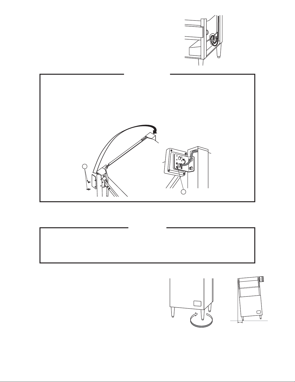
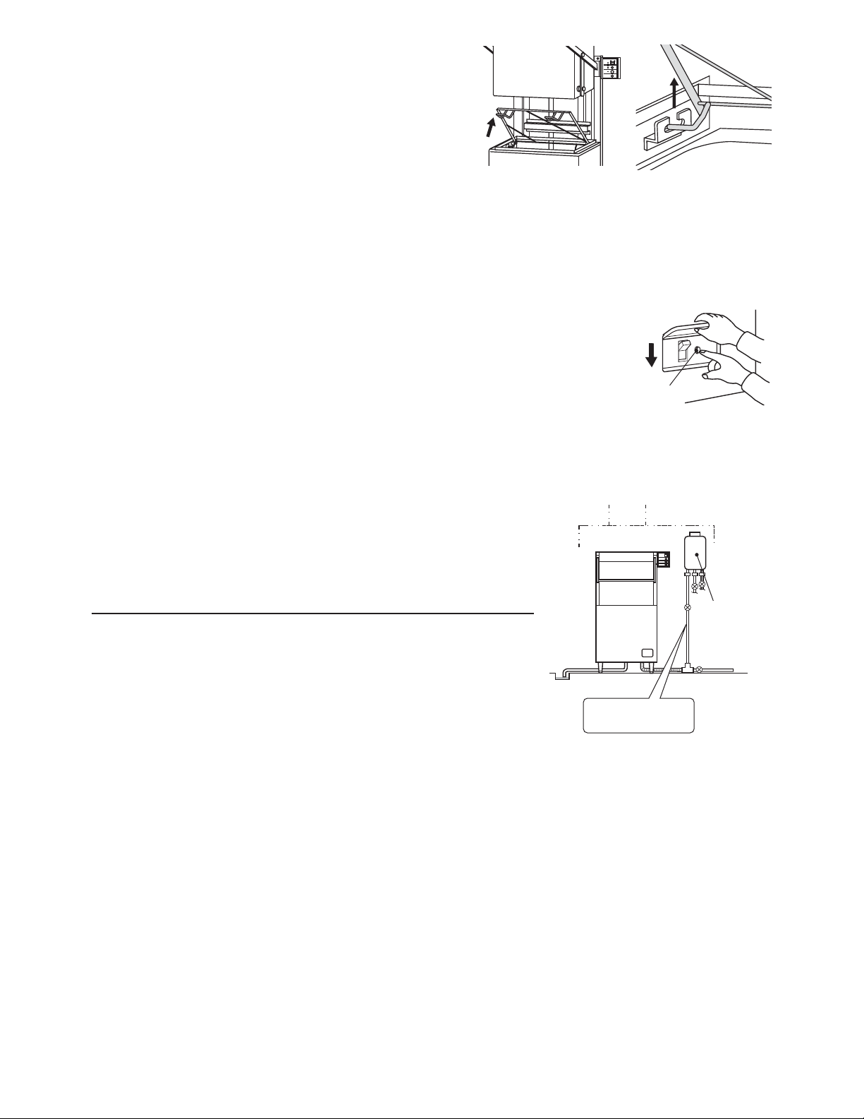
[d] OPERATION PANEL
Be sure to attach the operation panel before installing the unit. It is prepared at the factory
to be attached to the right side of the unit.
1) Loosen screws A on the pillar at the right side
Frame Cover
of the body (no need to remove). Then, remove
screw B at the front of the pillar to take off the
frame cover.
㪙
㪘
㪚
2) Insert the operation panel cable into the frame
(C), and route it into the machine compartment.
Then, attach the operation panel. Be careful not
to let the wiring touch the door opener.
3) Remove the front panel, and pull the cable from
the back of the machine compartment.
㪚
4) Remove the plastic bag from the operation
panel connection cable coming out of the
control box, and connect these cables.
3
Door Opener
Page 8
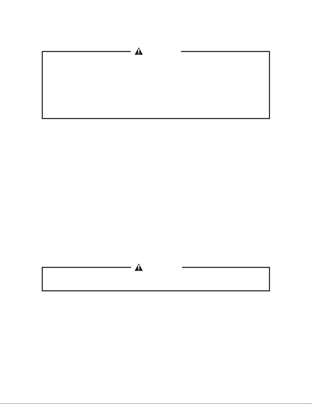
5) Cover the cable connection with the plastic
bag, and tie it upward as illustrated. Refi t the
front panel in its correct position.
IMPORTANT
To attach the operation panel to the left side, remove screws D from the
operation panel, turn the bracket upside down, and reattach it using the other
holes. Remove screws E and the cover, then attach them to the right side pillar.
Make sure that the wiring inside the machine compartment is clear of all moving
parts (i.e., fan motor).
㪜
㪛
[e] CONNECTION TO A DISHTABLE
CAUTION
When connecting a dishtable, apply silicone sealant to a thickness of at least
1/2” (12.7 mm) to the end of the mounting screw to prevent water leaks resulting
in electric leakage or shock.
A dishtable facilitates loading and unloading of the
rack.
1) Remove the side panel where the dishtable is
to be installed.
2) Use the adjustable legs of the dishtable and
dishwasher to level them in both the left-to-right
and the front-to-rear directions. The unit must
not tilt more than 1/2” (12.7 mm) as shown in
the illustration.
4
Adjustable
Leg
Turn clockwise
1/2" (12.7mm)
to adjust higher
Page 9
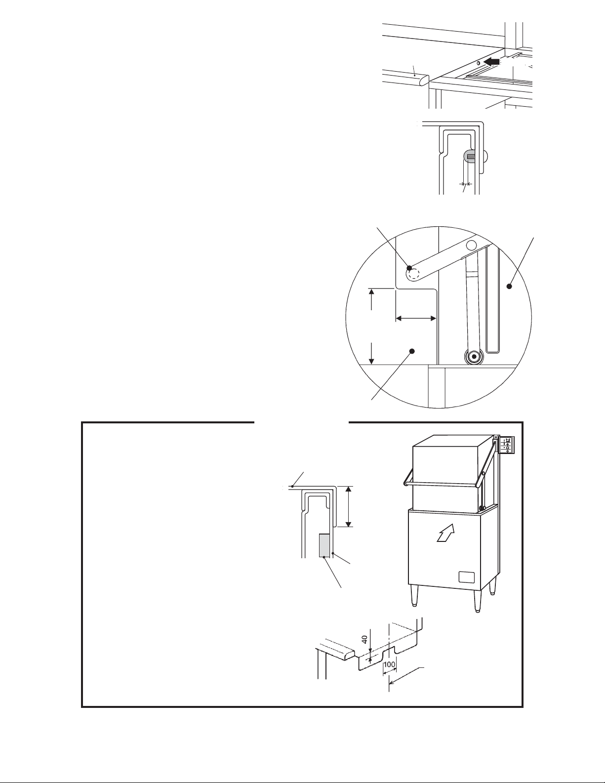
3) Hook the dishtable on the wash tank. Drill a hole in the
wash tank to match the mounting hole in the dishtable.
4) Secure the dishtable to the dishwasher with a screw.
Apply silicone sealant to the screw threads as shown
on the right and between the dishtable and the wash
tank.
Dishtable
Dishwasher
ⓣࠍߌࠆ
Drill a hole
5) Refi t the side panel in its correct position.
6) For corner installation, if the side of the
dishtable located at the front of the dishwasher
is 9” (229 mm) or higher, the door handle will
hit the dishtable. In this case, make a notch in
the dishtable as shown on the right.
Make additional adjustments to the dishtable,
if necessary, to improve the tightness between
the dishtable and the dishwasher or to facilitate
loading and unloading of the rack.
IMPORTANT
1. To prevent possible corrosion,
do not leave any shavings after
drilling the hole in the wash tank.
Dishtable
Min 1/2"
(12.7mm)
Door Handle
Door
5"
(127mm)
9"
(229mm)
Dishtable
2. To connect a dishtable to the
front of the dishwasher, keep the
hook on the wash tank within 1.6”
(40 mm) from the rim. Otherwise
the built-in door switch may not
operate properly.
If this is not practical, make a
notch as shown on the right.
3. See “DISHTABLE REFERENCE
DRAWINGS” D05003, D05004,
D05005, and D05006 at the end
of the service manual (80VC-782)
for details.
Max 1.6"
(40mm)
Front
Tank
Door Switch
Dishwasher front
center line
5
Page 10

[f] RACK GUIDE
The rack guide helps ease the load and unload the rack smoothly. It is provided in the
package of accessories together with the securing bolts.
The rack guide location depends on the installation conditions.
Straight Installation
Dishwasher
Rear
Dishtable
Front
Rack Guide
Dishtable
Corner Installation
Dishwasher
Dishtable
Rack Guide
Rear
Front
Secure the rack guide tightly with the two hexagon bolts.
Dishwasher
Dishtable
Front
Rack Guide
Rear
Rack Guide
6
Page 11

3. VENTILATION
WARNING
1. Installation must be in accordance with applicable national, state, and local
regulations.
2. If an exhaust hood is required to discharge steam from the dishwasher, it
should provide a minimum 450 CFM and be a listed and labeled factory-built
commercial exhaust hood tested in accordance with UL Standard 710 by a
nationally recognized testing laboratory.
It must be installed according to the terms of its listing and the manufacturer’s
installation instructions.
3. To use a gas water heater, thoroughly read its instruction manual. Ensure
adequate air intake and exhaust systems and exhaust hoods in accordance
with applicable national, state, and local regulations for the type and capacity
of the heater to prevent dangerous conditions due to lack of oxygen and toxic
gas generation.
Only qualifi ed service personnel should install the above systems.
4. WATER SUPPLY AND DRAIN CONNECTIONS
WARNING
Plumbing connections must comply with applicable sanitary, safety and
plumbing codes.
CAUTION
To prevent water leaks resulting in damage to the surrounding property, make
proper water supply and drain connections according to this manual.
[a] WATER HEATER CONNECTION
Make the water heater connection according to its instruction manual.
[b] PRESSURE REDUCING VALVE
Keep the water supply pressure within 10 to 70 PSIG.
If the water pressure is too high, a pressure reducing valve (not supplied) must be installed
in the water line just ahead of the dishwasher.
7
Page 12

CAUTION
The pressure reducing valve must have a relief by-pass. Failure to use the
proper type of pressure reducing valve may result in damage to the unit.
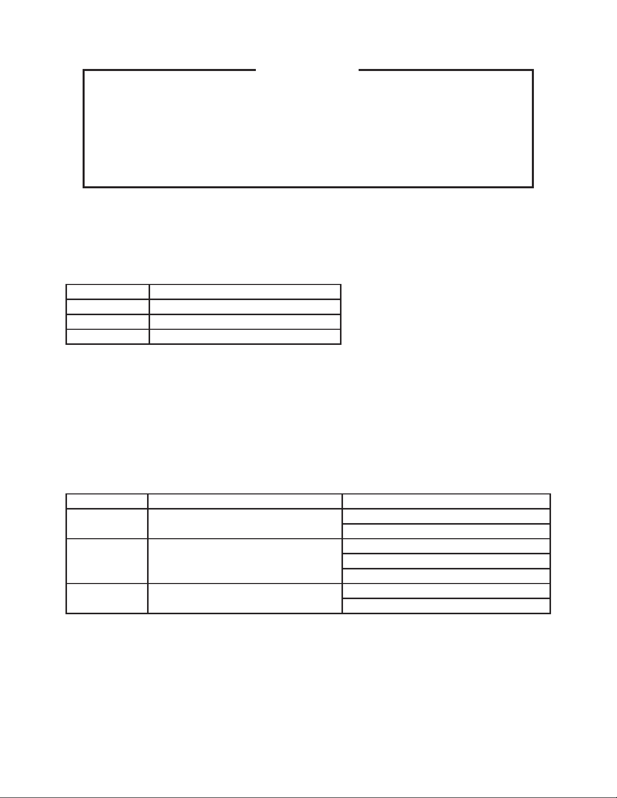
[c] WATER SOFTENER
If water hardness exceeds 4 grains per gallon, a water softener (not supplied) must be
installed in the primary circuit (water supply inlet) of the water heater.
IMPORTANT
The recommended water hardness of not more than 4 grains per gallon is for
the dishwasher. If the required water hardness for the water heater is lower,
meet that requirement.
* External fi lters and strainers may be required depending on water quality. Contact your
local Hoshizaki distributor for recommendations.
* Sediment, silica, chlorides or other dissolved solids may lead to a recommendation for
particulate fi ltration or reverse osmosis treatment.
* If an inspection of the dishwasher or booster heater reveals lime build-up after the
equipment has been in service, in-line water treatment should be considered, and, if
recommended, should be installed and used as directed.
Water
Heater
Water Softener
Water Supply Line
Shut-off Valve
Water
Strainer
(3/4" FPT)
Wash Tank
Drain Pipe
Dishwasher
Water Supply
Valve
Water
Hammer
Arrestor
Gas
Gas Supply Line
Shut-off Valve
Wash Tank Drain Hose
Fitting (1-1/2" MPT)
Drain Valve
Pressure Reducing
Valve with By-pass
8
Page 13

[d] STRAINER
Attach the strainer (accessory) to the water supply
pipe on the bottom front of the unit. To prevent water
leaks, be sure to insert the rubber gasket (accessory)
between the water supply pipe nut and the strainer.
Tighten Loosen
Gasket (accessory)
Water Supply Pipe
FPT
NPT
Strainer (accessory)
Bottom
[e] HOT WATER SUPPLY CONNECTION
WARNING
To reduce the risk of burns, the hot water supply line must be thermally
insulated. Hot water around 167°F (75°C) will fl ow inside.
* Where there is a risk of water hammer, it is recommended to install a water hammer
arrestor between the dishwasher and water heater.
* Required incoming water temperature:
Incoming Water Temperature
Minimum Recommended Maximum
110
°F (43°C)
140
°F (60°C)
If water is supplied at a temperature below 110°F (43°C), the dishwasher cannot maintain
the proper rinse water temperature and may require a longer wash cycle time than the 53
second cycle. In such case, consult with an authorized Hoshizaki service company.
167
°F (75°C)
Wash Temperature Rinse Temperature
Minimum Recommended Minimum Recommended
°F (66°C) 150°F (66°C) 180°F (82°C) 180°F (82°C)
150
* Optional connection for low temperature conditions:
Where there is a risk of freezing, install a drain valve (shut-off valve) between the water
supply valve and dishwasher.
IMPORTANT
When an instantaneous water heater is used, it must be an exclusive type for a
dishwasher and provided with an end stop system.
9
Page 14

[f] DRAIN CONNECTION (WASH TANK DRAIN)
CAUTION
To ensure proper draining, do not route the drain pipe where it can be stepped
on.
* Drain line should be pitched (1/4” per foot) to the floor
drain. An air gap of a minimum of 2 vertical inches (5 cm)
Drain Pipe
(pitched)
should be between the end of the drain pipe from the
dishwasher and the fl oor drain.
* If a grease trap is required in the drain line by regulations,
Floor Drain
check that it is present at the time of installation.
5. ELECTRICAL CONNECTION
WARNING
1. Electrical connection must be hard-wired and must meet national, state, and
local electrical code requirements. Failure to meet these code requirements
could result in death, electric shock, serious injury, fi re, or extensive damage
to equipment.
2. This unit requires an independent power supply. See the nameplate for
proper voltage and breaker/fuse size. Failure to use a proper breaker or fuse
can result in a tripped breaker, blown fuses, or damage to existing wiring.
This could lead to heat generation or fi re.
Min 2"
(5cm)
3. THIS UNIT MUST BE GROUNDED. Failure to properly ground this unit could
result in death or serious injury.
4. Make sure the power supply is off before making any electrical connections
to prevent possible electric shock. Lockout/Tagout to prevent the power from
being turned back on inadvertently.
Electrical Specifi cations
(Also Refer to the Dishwasher Nameplate)
AC Supply Voltage Maximum Breaker/Fuse Size Minimum Circuit Ampacity
208 - 230V / 60Hz / 3Ph 50A 50A
* Usually an electrical permit and services of a licensed electrician are required.
10
Page 15
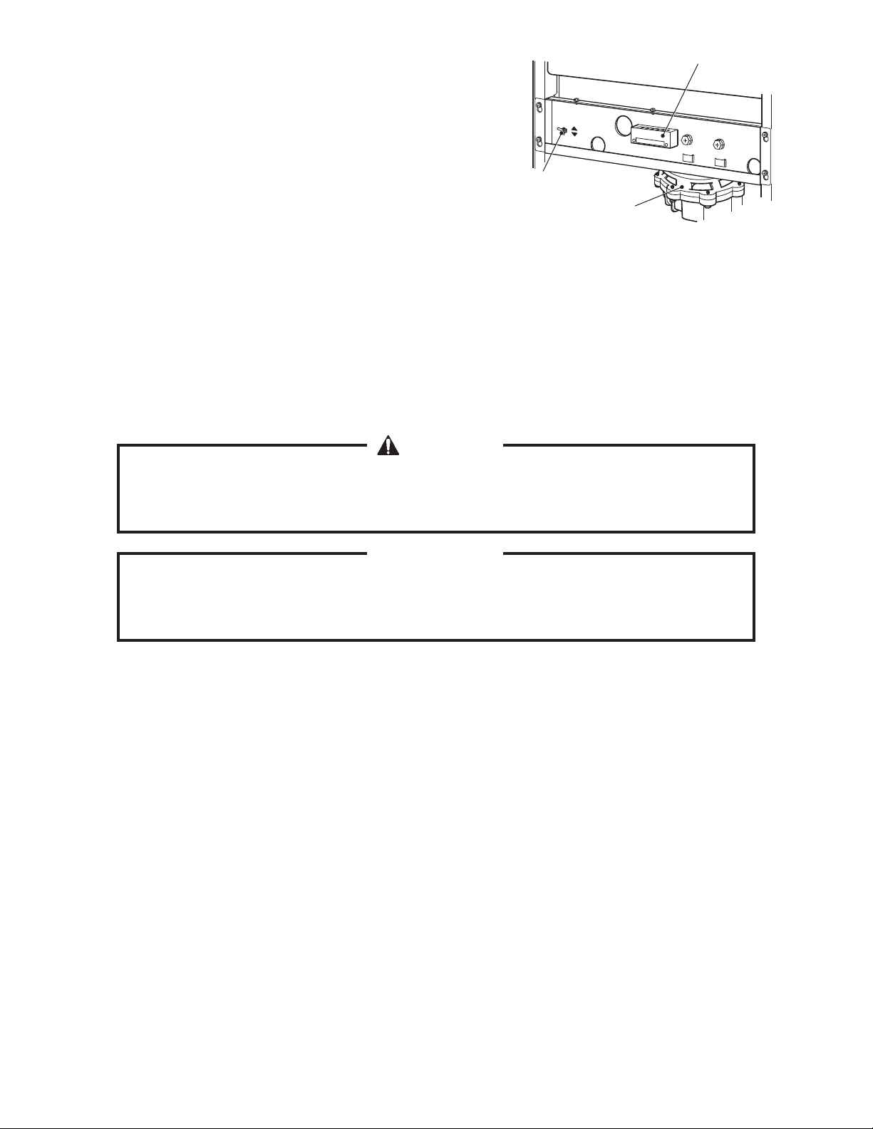
* The maximum allowable voltage variation is ±10
percent of the nameplate rating.
Terminal Block
* The voltage tap switch in the unit must be
positioned to match incoming voltage at startup
230V
208V
(factory default: 230V).
Voltage Tap Switch
* The opening for the power supply connection is
1.11” DIA to fi t a 3/4” trade size conduit.
Pump Motor
1) Remove the front panel.
2) Remove the 3 screws securing control box cover (A), then remove the cover.
3) Connect the ground wire to the ground screw in the base.
4) Route the 3 power wires through the 27.5” (700 mm) UL tube provided and then through
the strain relief in the control box next to the power switch (GFCI).
WARNING
The UL tube must slope downward from the strain relief to prevent entrance of
water through the strain relief into the control box.
IMPORTANT
Do not cut the UL tube. The extra length allows the control box to be pulled out
for service after installation.
5) Securely connect M8 ring terminals to the ends of the wires, then connect the ring
terminals to the terminals on the power switch (GFCI).
6) If the control box has been moved, carefully slide the control box into its correct position
while taking care not to catch the wires. Make sure the rear of the control box has
engaged the tab in the base.
7) Make sure the strain relief is in its proper position, then secure control box cover (A)
using the 3 screws.
8) Use the wire retainer in front of the rinse pump motor to secure the UL tube.
9) Reattach the front panel.
11
Page 16

Downgrade
Control Box Cover (A)
* Remove 3 screws
Wire
Retainer
UL T ube
Conduit
Grounding
Grommet
Cable Tie
6. PHASE REVERSAL CHECK
The unit is provided with a phase reversal relay to prevent operation in case of phase
reversal. To check for phase reversal, follow the steps below.
1) Make sure all wiring connections have been properly made. For details, see “5.
ELECTRICAL CONNECTION”.
2) Turn on the power supply, then move the power switch (GFCI) to the “ON” position.
3) If the display is blank, move the power switch (GFCI) to the “OFF” position, turn off the
power supply, then skip to the next section. If the display shows “H7”, move the power
switch (GFCI) to the “OFF” position, then proceed to step 4.
4) Turn off the power supply. Lockout/Tagout to prevent the power from being turned back
on inadvertently.
5) Swap 2 of the power wires attached to the power switch (GFCI).
6) Turn the power supply back on, then move the power switch (GFCI) to the “ON” position.
Confi rm that the display does not show “H7”.
7) Move the power switch (GFCI) to the “OFF” position, then turn off the power supply.
12
Page 17

7. DETERGENT/RINSE AID FEEDER
WARNING
1. Electrical connection must be hard-wired and must meet national, state, and
local electrical code requirements. Failure to meet these code requirements
could result in death, electric shock, serious injury, fi re, or extensive damage
to equipment.
2. THIS UNIT MUST BE GROUNDED. Failure to properly ground this unit could
result in death or serious injury.
This dishwasher must be operated with an automatic detergent feeder and an automatic
rinse aid feeder, including a visual means to verify that detergents/rinse aids are delivered
or to signal if detergents/rinse aids are not available for delivery.
Any feeders provided by a detergent supplier must be installed in the location shown
below. For electrical and plumbing connections, follow the instructions in this manual and
the manual supplied with the feeder. Consult with the detergent supplier or an authorized
Hoshizaki service company for further details.
The dishwasher uses 0.53 gallons of rinse water per rack. This information is use when
setting a detergent/rinse aid pump.
Concentration Sensor Detergent Inlet Terminal Block* Rinse Aid Inlet
(one on each side)
Tank
Interior
22mm
hole
Cap
Nut
O-ring
Tank
Wall
Nut
22mm
hole
Tank Wall
Tank
Exterior
O-ring
Tank
Interior
Cap
1/8-27 NPT
* Connect external detergent and rinse
aid feeders to this terminal block.
Terminal Block
Wash Pump
Use insulated terminals.
Power supply for the detergent and
rinse aid feeders is available with this
Rinse Pump
terminal block. For details, see the
wiring diagram below.
Plug
Booster Tank
Control Box
Rinse Aid Inlet
13
Page 18

IMPORTANT
1. Be sure to use detergent and rinse aid feeders with protective fuses.
2. Ensure the power supply capacity of 208 to 230VAC, 1A or less, and use
insulated terminals to connect the feeders to the terminal block.
* MC2 is synchronized with wash pump and X13 with rinse
External Detergent
and Rinse Aid Feeder
pump (except auto fi ll). See wiring label for details.
Dishwasher
6
5
4
3
2
1
Rinse Aid Solenoid
L3-230VAC
From X13 (#3)
L3-230VAC
From MC2 (#14)
Detergent Solenoid
Available If Needed
Available If Needed
Detergent and Rinse Aid
Terminal Block
If a hole is necessary in the side panel to allow the detergent
inlet to the wash tank, take off the side panel, and remove the
aluminum foil tape and hole cover.
8. TRIAL RUN
L2-230VAC (BR)
L3-230VAC (BK)
From X13 (#3) (W/R)
From MC2 (#14) (W/BK)
Hole Cover
Rinse Cycle
Wash Cycle
WARNING
To reduce the risk of electric shock, do not touch the attachment plug, power
switch (GFCI), or other electrical parts with damp hands.
[a] CHECKS BEFORE TRIAL RUN
1) Check that the door, upper and lower wash/
rinse spray arms, power switch cover, and
other moving parts move smoothly.
2) Fit the separator in the wash tank, and
install the tank fi lters.
Separator
14
Tank Filter
Page 19

3) Insert the drain pipe securely.
4) Lower the rack rail. With the rack rail lifted
Insert drain pipe
securely
up, the door cannot be closed and the unit
will not operate.
[b] PREPARING HOT WATER SUPPLY
1) If the optional drain valve for low temperature conditions is installed, close the drain
valve provided to prevent freezing.
2) Open the water supply valve.
3) Follow the instructions in the water heater’s instruction manual.
[c] FINAL CHECKS
1) Is an independent three-phase 208 to 230V disconnect used?
2) Is the voltage tap switch behind the front panel set to the proper voltage?
3) Is the power cord connected securely to the disconnect?
4) Has a proper ground connection been made?
5) Have all electrical, hot water, drain, and gas connections been made? Do electrical,
hot water, drain, and gas connections meet all national, state, and local code and
regulation requirements?
6) Are the gas and water supplies to the water heater turned on?
7) Turn on the water heater, move the power switch (GFCI) of the dishwasher to the “ON”
position, then press the “ON/OFF” button on the operation panel. Has the display lit
up?
* If yes, the auto fi ll cycle begins when the door is closed.
15
Page 20

8) Is the display showing “H7”? If yes, correct the reverse phase connection according to “6.
PHASE REVERSAL CHECK”.
9) Has the operation (auto fi ll, wash, rinse, mode selection) been checked against the
instruction manual?
10) Remove the front panel. Make sure there are no water leaks in the machine
compartment.
11) Does a sufficient amount of detergent and rinse aid remain in the tanks? Are they
properly supplied to the dishwasher?
12) Has the user been instructed on proper operation of the dishwasher?
13) Have the instruction and installation manuals been given to the user?
[d] AFTER TRIAL RUN
WARNING
When cleaning the strainer at the end of installation, wait until the surface
temperature falls below 104°F (40°C) to avoid the risk of burns.
CAUTION
Do not install the unit where there is a risk of freezing. If there is a possibility
that the ambient temperature may fall below 32°F (0°C) and freeze the unit, be
sure to drain the unit. The water supply line could be damaged and leak water,
resulting in damage to the surrounding property.
1) Press the “ON/OFF” button, and move the power switch (GFCI) to the “OFF” position.
2) Pull out the drain pipe to drain wash water from the wash tank.
3) Turn off the water heater according to its instruction manual.
4) Clean the strainer to remove any debris from the
water supply and drain connections. To remove
the strainer, turn the cap counterclockwise.
Strainer
Cap
Mesh
5) Use a dry soft cloth to wipe moisture off the
exterior and washing compartment.
16
Page 21

[e] ADJUSTMENT
If any adjustment is required to the wash or rinse cycle time or temperature setting, contact
an authorized Hoshizaki service company.
9. RELOCATION
WARNING
1. Make sure the power supply is off before making any electrical connections
to prevent possible electric shock. Lockout/Tagout to prevent the power from
being turned back on inadvertently.
2. When draining the booster tank and hot water supply line at the time of
relocation, wait until the surface temperature falls below 104°F (40°C) to
avoid the risk of burns.
1) Shut down and clean the unit according to the instruction manual.
2) Ask the detergent supplier to treat the detergent and rinse aid tanks and pipes.
3) To drain the booster tank, remove the front
panel, take out the end of the drain hose, and
remove the plug.
4) Disconnect the electrical, water supply and
drain connections.
Booster Tank
5) Move the unit with care not to damage it.
Drain Hose
6) Reinstall the unit properly according to this
installation manual.
Band
Plug
17
Page 22

DISHWASHER
INSTRUCTION MANUAL
JWE-620UA-6B
FOR END USER
9180VC10B (041111)
Page 23

IMPORTANT
Only qualified service technicians should install, service and maintain the
product. No installation, service or maintenance should be undertaken until
the technician has thoroughly read this Instruction Manual. Likewise, the
owner/manager should not proceed to operate the product until the installer
has instructed them on its proper operation. Failure to install, operate, and
maintain the equipment in accordance with this manual may adversely affect
safety, performance, component life, and warranty coverage.
Hoshizaki provides this manual primarily to assist qualified service technicians in the
installation, maintenance, and service of the product.
Should the reader have any questions or concerns which have not been satisfactorily
addressed, please call, write, or send an e-mail message to the Hoshizaki Technical
Support Department for assistance.
HOSHIZAKI AMERICA, INC.
618 Highway 74 South
Peachtree City, GA 30269
Attn: Hoshizaki Technical Support Department
Phone: 1-800-233-1940 Technical Support
(770) 487-2331
Fax: 1-800-843-1056
(770) 487-3360
E-mail: techsupport@hoshizaki.com
Web Site: www.hoshizaki.com
NOTE: To expedite assistance, all correspondence/communication MUST include the
following information:
* Model Number
* Serial Number
* Complete and detailed explanation of the problem.
i
Page 24

IMPORTANT
This manual should be read carefully before the product is installed and
operated. Only qualified service technicians should install, service, and
maintain the product. Read the warnings contained in this booklet carefully as
they give important information regarding safety. Please retain this booklet for
any further reference that may be necessary.
CONTENTS
1. CONSTRUCTION --------------------------------------------------------------------------------------1
[a] GENERAL --------------------------------------------------------------------------------------------1
[b] OPERATION PANEL -------------------------------------------------------------------------------3
[c] ACCESSORIES -------------------------------------------------------------------------------------4
2. CHECKS BEFORE OPERATION -------------------------------------------------------------------4
[a] CHECKS AFTER INSTALLATION --------------------------------------------------------------5
[b] WATER REQUIREMENTS -----------------------------------------------------------------------5
[c] CHECKS BEFORE OPERATION---------------------------------------------------------------5
3. CHECKING DETERGENT TANK AND RINSE AID TANK ------------------------------------6
4. PREPARING THE WASH COMPARTMENT -----------------------------------------------------6
[a] AUTO FILL -------------------------------------------------------------------------------------------8
5. LOADING -------------------------------------------------------------------------------------------------8
[a] PREWASH -------------------------------------------------------------------------------------------8
[b] LOADING DISHES ---------------------------------------------------------------------------------9
[c] LOADING RACK ------------------------------------------------------------------------------------9
PAGE
6. WASH AND RINSE ----------------------------------------------------------------------------------- 10
[a] OPERATING TEMPERATURES -------------------------------------------------------------- 10
[b] MODE SETTING --------------------------------------------------------------------------------- 10
7. UNLOADING --------------------------------------------------------------------------------------------11
8. INSUFFICIENT WASHING RESULTS------------------------------------------------------------11
9. SHUTDOWN ------------------------------------------------------------------------------------------- 12
10. INTERRUPTION -------------------------------------------------------------------------------------- 13
11. STANDBY/CLEANING BUTTON ----------------------------------------------------------------- 14
12. INTERNAL BOOSTER TANK ENERGY SAVING CONTROL ----------------------------- 14
ii
Page 25

13. LOW WATER TEMPERATURE LOCK FUNCTION ------------------------------------------ 14
14. ALERT FUNCTION ----------------------------------------------------------------------------------- 14
15. DAILY MAINTENANCE ----------------------------------------------------------------------------- 15
16. SELF-CLEANING ------------------------------------------------------------------------------------- 17
17. WEEKLY MAINTENANCE -------------------------------------------------------------------------- 18
[a] HEATER -------------------------------------------------------------------------------------------- 18
[b] EXTERIOR ----------------------------------------------------------------------------------------- 18
[c] WASH COMPARTMENT ------------------------------------------------------------------------ 19
18. MONTHLY INSPECTION --------------------------------------------------------------------------- 19
[a] POWER SWITCH (GROUND FAULT CIRCUIT INTERRUPTER) ------------------- 19
[b] WATER SUPPLY LINE -------------------------------------------------------------------------- 19
19. DESCALING (AS REQUIRED) -------------------------------------------------------------------- 20
20. TROUBLESHOOTING ------------------------------------------------------------------------------ 21
[a] TROUBLES REQUIRING IMMEDIATE SERVICE CALL -------------------------------- 21
[b] TROUBLES REQUIRING CHECK BY USER ---------------------------------------------- 21
[c] TROUBLES WITHOUT ERROR CODE INDICATION -----------------------------------22
21. LONG STORAGE, RELOCATION, DISPOSAL, TRANSFER ----------------------------- 23
iii
Page 26

Important Safety Information
Throughout this manual, notices appear to bring your attention to situations which could
result in death, serious injury, or damage to the unit.
WARNING
CAUTION
Indicates a situation which could result in damage to the unit.
IMPORTANT
This product should be destined only to the use for which it has been
expressly conceived. Any other use should be considered improper and
therefore dangerous. The manufacturer cannot be held responsible for injury
or damage resulting from improper, incorrect, and unreasonable use.
To reduce the risk of death, electric shock, serious injury, or fi re, follow
basic precautions including the following:
• Electrical connection must be hard-wired and must meet national, state, and
local electrical code requirements. Failure to meet these code requirements
could result in death, electric shock, serious injury, fi re, or severe damage to
equipment.
• This unit requires independent power supplies for the dishwasher and for the
booster tank. See the nameplate for proper voltage and breaker/fuse sizes.
Failure to use proper breakers or fuses can result in tripped breakers, blown
fuses, or damage to existing wiring. This could lead to heat generation or
fi re.
• THIS UNIT MUST BE GROUNDED. Failure to properly ground this unit
could result in death or serious injury.
• This unit should be disassembled or repaired only by qualified service
personnel to reduce the risk of electric shock, injury, or fi re.
• Do not make any alterations to the unit. Alterations could result in electric
shock, injury, fi re, or damage to the unit.
Indicates a hazardous situation which could result in death or
serious injury.
Indicates important information about the use and care of the
unit.
WARNING
iv
Page 27

1. CONSTRUCTION
[a] GENERAL
[5]
[6]
[1]
[4]
Rear View
[3]
[2]
[7]
[8]
[9]
[10]
[11]
[12]
[13]
[14]
1
Page 28

[1] Upper Rinse Spray Arm, Lower Rinse Spray Arm
Rotates and sprays rinse water onto dishes to rinse off detergent.
[2] Upper Wash Spray Arm, Lower Wash Spray Arm
Rotates and sprays wash water onto dishes to remove stains.
[3] Heater
Keeps wash water at a proper temperature.
[4] Water Level Sensor
Detects wash water level.
[5] Handle
[6] Door
[7] Operation Panel
See “[b] OPERATION PANEL”.
[8] Rack Rail
[9] Drain Pipe
Pull out to drain.
[10] Separator
[11] Tank Filter
Separates wash water and scraps.
[12] Pump Filter
Prevents scraps from being drawn into the pump.
[13] Power Switch (Ground Fault Circuit Interrupter)
Move the lever to start up or shut down the unit. Automatically turns off the power in
case of a ground fault.
[14] Vent
2
Page 29

[b] OPERATION PANEL
[1]
[2]
[3]
[5]
[6]
[7]
[8]
[4]
[9]
[1] “READY” Lamp
Lights up when the auto fi ll cycle completes and the dishwasher is ready to wash.
[2] “AUTO FILL” Lamp
Flashes during the auto fi ll cycle, and goes off at the end of the cycle.
[3] Mode Lamps
Light up to indicate the selected operation mode, and fl ash during operation.
[4] Standby Lamp
Lights up when the dishwasher is in the standby mode. The unit will not start even
when the door is closed with this lamp on. See “11. STANDBY/CLEANING BUTTON”.
3
Page 30

[5] Up Button, Down Button
Indicates the total number of operation in six digits by two digits each time.
Example: 123,456 times are indicated by
Press to indicate rinse water temperature instead of wash water temperature while
the dishwasher is on standby.
Serv
[6] Display
Indicates wash water temperature in wash cycle, rinse water temperature in rinse
[7] “MODE” Button
Press to change the selected operation mode. See “6. WASH AND RINSE”.
[8] “STANDBY/CLEANING” Button
Press to make the dishwasher inoperable even when the door is closed. See “11.
Press and hold to start self-cleaning with the “ON/OFF” button off. See “16. SELF-
[9] “ON/OFF” Button
Turns on/off the power for operation.
ice personnel also use these buttons to change the controller settings.
cycle, and error codes in case of trouble. See “20. TROUBLESHOOTING”.
STANDBY/CLEANING BUTTON”.
CLEANING”.
[c] ACCESSORIES
Instruction manual x 1 Installation manual x 1
Universal rack x 1 Maintenance sheet x 1
Required for installation:
Operation panel x 1 Plate - rack guide x 1
Screw - bolt (stainless steel 5x12) x 2 Inlet water strainer & gasket x 1
2. CHECKS BEFORE OPERATION
WARNING
1. To prevent possible water leak, electric shock or fi re, the installation must be
carried out by qualifi ed personnel.
2. To use a gas water heater, thoroughly read its instruction manual. Ensure
adequate air intake and exhaust systems and exhaust hoods in accordance
with applicable laws for the type and capacity of the heater to prevent
dangerous conditions due to lack of oxygen and toxic gas generation.
4
Page 31

[a] CHECKS AFTER INSTALLATION
* In the presence of the installer, check for proper installation according to the installation
manual provided.
* Receive the installation manual from the installer, and keep it for later reference.
[b] WATER REQUIREMENTS
* Proper water quality can improve warewashing performance by reducing spotting,
lowering chemical supply costs, improving productivity and extending equipment life.
Local water conditions vary. The recommended proper water treatment for effective and
effi cient use of this equipment will also vary depending on the local water conditions. Ask
your municipal water supplier for details about local water specifi cs prior to installation.
* Recommended water hardness is not more than 4 grains of hardness per gallon.
Chlorides must not exceed 50 parts per million. Water hardness above 4 grains per gallon
should be treated by a water softener or in-line treatment. Water treatment has been
shown to reduce costs associated with machine cleaning, reduce the need for deliming
the dishwasher, reduce detergent usage and reduce corrosion of metallic surfaces in the
internal booster tank and dishwasher.
* Sediment, silica, chlorides or other dissolved solids may lead to a recommendation for
particulate fi ltration or reverse osmosis treatment.
* If an inspection of the dishwasher or internal booster tank reveals lime build-up after
the equipment has been in service, in-line water treatment should be considered, and,
if recommended, should be installed and used as directed. Contact an authorized
Hoshizaki service company for specifi c recommendations.
[c] CHECKS BEFORE OPERATION
* Ambient temperature should be within 41 to 95°F (5 to 35°C). Operation of the unit for
extended periods outside of this normal temperature range may affect performance.
WARNING
To avoid the risk of corrosion, clogging and health problems, be sure to use
potable water.
* To prevent water leaks resulting in damage to the surrounding property, keep the water
supply pressure within 10 to 70 PSIG. If the water pressure is too high, a pressure
reducing valve (option) must be installed according to the water heater’s instruction
manual.
5
Page 32

* The power supply voltage and capacity must be as follows:
Power supply voltage: 208 - 230V / 60Hz / 3Ph
Operating limits: 187 - 253V
Maximum breaker/fuse size: 50A
Minimum circuit ampacity: 50A
* The wash compartment has been cleaned before shipping. But clean it again before
starting up the unit, and check for proper installation of each part. See “15. DAILY
MAINTENANCE”.
* Check the electrical, water, and drain connections before starting up the unit. See “18.
MONTHLY INSPECTION”.
* Always use a dishwasher detergent instead of a neutral detergent for kitchen use.
(Some dishwasher detergents are not suitable. Contact an authorized Hoshizaki service
company for further details.)
3. CHECKING DETERGENT TANK AND RINSE AID TANK
* Follow the instructions of the detergent and rinse aid suppliers to check the detergent
tank and rinse aid tank safely.
IMPORTANT
Be sure to read the warning and caution labels attached to the detergent tank
and rinse aid tank.
4. PREPARING THE WASH COMPARTMENT
* Check that the wash compartment has been cleaned with all the parts in place. If not,
clean the wash compartment according to “13. DAILY MAINTENANCE”, and install the
parts following the instructions below.
6
Page 33

Upper Wash Spray Arm
Upper Spray Arm Holder
Drain Pipe
Dishtable
Upper Rinse
Spray Arm
Lower Wash Spray Arm
Lower Rinse Spray Arm
Wash Compartment
Tank Filter
Dishtable
Pump Filter
Power Switch (GFCI)
1) Check that the tank fi lters and drain pipe are
in place.
Insert drain pipe
securely
Place left and right
tank fi lters in
position
2) Lower the rack rail. With the rack rail lifted
up, the door cannot be closed and the unit
will not operate.
3) Turn on the power supply to the water heater.
4) Open the cover in the front, and move the power switch (GFCI) to the “ON” position.
5) Press the “ON/OFF” button. The display lights up. (If the door is closed, the auto fi ll
cycle begins.)
7
Page 34

[a] AUTO FILL
The auto fi ll cycle refers to automatically repeated starts and stops of the unit to fi ll the
wash tank with enough hot water for washing. The unit starts and stops about 24 times
and the cycle takes around 11 minutes (supply voltage: 208V, hot water supply: 24 PSIG,
143°F). Then, the dishwasher is ready for washing.
1) Close the door. The “AUTO FILL” lamp fl ashes, and the auto fi ll cycle starts.
2) After the auto fi ll cycle completes, the unit stops, the “READY” lamp lights up (“AUTO
FILL” lamp goes off), and the buzzer sounds.
IMPORTANT
If the dishwasher has been drained
out to prevent freezing, close the
drain valve before opening the water
supply line shut-off valve. With the
drain valve left open, hot water will
be wasted.
Gas Supply Line
Shut-off Valve
Water Supply Line
Shut-off Valve
Water Supply Valve
Water Heater
Water
Gas
Drain Valve
Dishwasher
5. LOADING
[a] PREWASH
1) Remove any leftovers (ex. meat, fi sh, vegetables), chopsticks, toothpicks, straws, paper
products and plastics from the dishes. Never use steel wool on ware to be loaded into
the dishwasher.
CAUTION
Do not put these scraps in the dishwasher, as this may cause reduction in wash
performance or failure.
2) To remove heavy soils such as baked gratin and steamed egg or rice, soak the dishes in
hot water before loading them in the dishwasher.
IMPORTANT
1. Do not allow a large amount of neutral detergent in the dishwasher.
2. Use a suitable rack for dishes.
8
Page 35

[b] LOADING DISHES
1) Place the rack on the dishtable.
2) Keep the dishes within the rack, otherwise they
may be damaged.
3) Do not stack the dishes, otherwise they cannot be
washed properly.
Correct
Incorrect
Stacked Sticking out
Facing up
4) Load glasses upside down into the glassware
rack, otherwise they cannot be washed properly
Correct
Incorrect
Water remains
and rinsed thoroughly or they may touch each
other and be damaged.
Dishes or cups with a deep bottom rim cannot be
rinsed thoroughly with wash water left inside the
rim. Load them as shown below.
Correct
Incorrect
Water remains
If the above loading is not practical, the rinse cycle
time must be extended. Contact an authorized
Hoshizaki service company for further details.
5) The door opening is about 18” (457 mm) high. Keep the loaded rack lower than this
height. Do not force large items into the dishwasher, otherwise they may be damaged or
block the spray arms.
[c] LOADING RACK
1) Slowly open the door.
2) Push the rack into the center of the dishwasher until it touches the rack guide at the
back. Otherwise, the rack and dishes may get caught on the back of the door, resulting
in damaging the wash and rinse spray arms and dishes.
CAUTION
Do not stack racks. Otherwise, this will
cause reduction in wash performance
or failure.
9
Door
Rack
Page 36

6. WASH AND RINSE
[a] OPERATING TEMPERATURES
Operating temperatures are as follows:
Wash Temperature Rinse Temperature
Minimum Recommended Minimum Recommended
°F (66°C) 150°F (66°C) 180°F (82°C) 180°F (82°C)
150
[b] MODE SETTING
Standard mode: Normal soils (about 53 seconds)
Long mode: Heavy soils (about 122 seconds)
Rinse mode: Rinse only (6 seconds)
1) Press the “MODE” button until the desired mode is selected and its lamp lights up.
2) Slowly close the door. The selected mode lamp fl ashes (“READY” lamp goes off), and
washing operation (wash and rinse) starts.
3) When the washing operation completes, the “READY” lamp lights up (mode lamp goes
off), and the buzzer sounds.
IMPORTANT
1. To change the duration of each mode, contact an authorized Hoshizaki
service company.
2. If the display has changed from temperature indication to
circling indication, the dishwasher is waiting for water supply.
In a wash cycle, the unit will automatically extend the wash
cycle and start a rinse cycle after completion of water supply.
In the rinse mode, the unit will wait for the water supply cycle
to complete and start a rinse cycle.
3. In case washing operation is interrupted by power failure or other reasons,
restart the washing operation from the beginning or select the rinse mode to
rinse off any detergent remaining on the dishes.
10
Page 37

7. UNLOADING
1) Slowly open the door.
2) Slide the rack onto the dishtable.
WARNING
1. To prevent the risk of burns, do not touch the hot water [140 to 176°F (60 to
80°C)] inside the wash tank directly.
2. When opening the door, be careful not to burn yourself with dripping hot
water.
3. To prevent possible burns, handle the rack, dishes, and interior parts [around
176°F (80°C)] with care after washing.
IMPORTANT
When carrying a loaded rack, use both hands to keep it level.
8. INSUFFICIENT WASHING RESULTS
If washing results seem insuffi cient, check for the following possible causes:
* Small items such as chopsticks and spoons or part of the dishes stick out of the rack to
block the spray arms. Remove the projecting items.
* The dishes are packed and stacked in the rack. Reload the dishes. See “5. [b] LOADING
DISHES”.
* The tank fi lters or pump fi lter is clogged. Clean them. See “15. DAILY MAINTENANCE”.
* The spray arm nozzles are clogged. Clean them. See “15. DAILY MAINTENANCE”.
* The upper and lower headers (spray arm shafts) are clogged
with small objects such as toothpicks. Clean them.
* The detergent tank is out of detergent. Replace it with a new
tank. See “3. CHECKING DETERGENT TANK AND RINSE
AID TANK”.
* Wash water is not clean. Press the “ON/OFF” button, check that the display goes off, and
pull out the drain pipe to drain the wash water. Reinsert the drain pipe, then press the “ON/
OFF” button to supply fresh wash water.
11
Header
Page 38

* The wash water temperature is too low.
* The dishes are heavily soiled. Preclean before loading the dishes.
* Iron or tannin content in wash water turns the dishes yellowish or faintly black. Soak the
dishes in a plastic bucket containing hot water and commercial bleach.
* White spots left on clear glassware can be caused by different reasons. Consult with an
authorized Hoshizaki service company or the detergent supplier.
* Adjustments of the wash and rinse cycle times, hot water temperature, and detergent
concentration may be required depending on the water quality, dish types and materials,
and soil conditions.
9. SHUTDOWN
CAUTION
If there is a possibility that the ambient
temperature may fall below 32°F (0°
C) and freeze the unit, be sure to drain
the unit. The water supply line could be
damaged and leak water, resulting in
damage to the surrounding property.
To drain out the water heater, close the
water supply line shut-off valve, and
open the drain valve and water supply
valve.
Gas Supply Line
Shut-off Valve
Water Supply Line
Shut-off Valve
Water Supply Valve
Water Heater
Water
Gas
Drain Valve
Dishwasher
1) Press the “ON/OFF” button on the operation panel. The display and lamps go off.
2) Open the cover in the front panel, then move the power switch (GFCI) to the “OFF”
position.
3) Turn off the water heater.
4) Turn off the gas and water supplies.
IMPORTANT
To operate the water heater, follow its instruction manual.
12
Page 39

5) Tilt back the rack rail.
IMPORTANT
The rack rail may fall down if tilted more than 10°. Do not hang anything from it
or hit it hard.
6) Pull out the drain pipe to drain water from the
wash tank.
7) Remove the right tank fi lter and then the left
tank fi lter without spilling scraps inside.
WARNING
When pulling out the drain pipe, be careful not to touch the wash water. It may
cause burns or skin irritation. Turn the drain pipe if it is hard to pull out.
10. INTERRUPTION
WARNING
To prevent hot water from splashing and causing burns, do not open the door
while the unit is running. Wait until the buzzer sounds 1 second after the unit
stops.
To interrupt washing operation, press the “ON/OFF” button on the operation panel. The
display and lamps go off, and the unit stops.
To resume operation, press the “ON/OFF” button.
13
Page 40

11. STANDBY/CLEANING BUTTON
The “STANDBY/CLEANING” button is used to keep wash water hot. It will cool more
quickly if the door is left open.
1) Press the “STANDBY/CLEANING” button on the operation panel. The standby lamp
lights up (“READY” lamp goes off). The unit will not start even when the door is opened
or closed.
2) To resume operation, press the “STANDBY/CLEANING” button on the operation panel.
The “READY” lamp lights up (standby lamp goes off). Now the dishwasher is ready to
wash.
IMPORTANT
The “STANDBY/CLEANING” button function is not available during washing
operation. Press it while the “READY” lamp is on.
12. INTERNAL BOOSTER TANK ENERGY SAVING CONTROL
The internal booster tank water temperature in the standby mode can be set lower to save
energy. For further details, consult with an authorized Hoshizaki service company.
13. LOW WATER TEMPERATURE LOCK FUNCTION
To ensure the NSF specified minimum wash and rinse water temperatures, this unit is
provided with functions to lock the washing operation until wash water reaches 150°F and
to extend the washing operation until rinse water reaches 180°F (factory default: OFF). For
further details, consult with an authorized Hoshizaki service company.
14. ALERT FUNCTION
To keep water in the wash tank clean, this unit is provided with functions to beep and fl ash
“Ch” (= Change) in the display when wash water should be changed and to continue this
alert until the wash water tank is refi lled (factory default: OFF). For further details, consult
with an authorized Hoshizaki service company.
14
Page 41
15. DAILY MAINTENANCE
IMPORTANT
Be sure to clean the dishwasher after closing time every day. It is diffi cult to
remove heavy soils left overnight. In high temperature conditions, food scraps
will rot and affect sanitary operation.
1) Take out scraps from the removed tank fi lters, and wash them clean with a scourer.
IMPORTANT
To prevent damage, do not hit the fi lters on the sink to drop scraps or to drain
the fi lters.
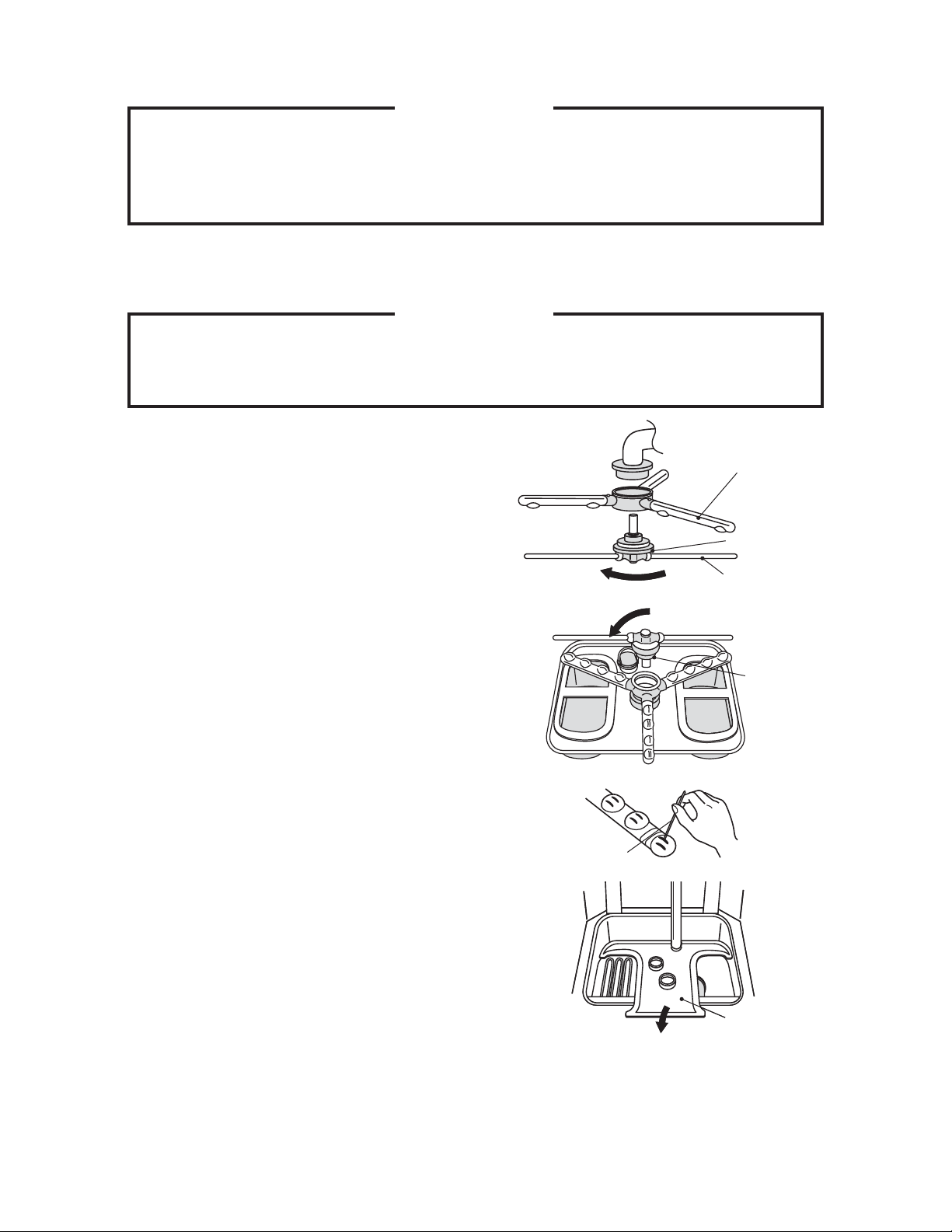
2) Turn and loosen the upper spray arm nut
in the direction of the arrow. Support the
upper rinse spray arm, and remove it
together with the upper wash spray arm.
3) Turn and loosen the lower spray arm nut in
the direction of the arrow. Lift off the lower
rinse spray arm, and remove the lower
wash spray arm.
4) If the wash spray arm and rinse spray arm
nozzles are clogged, use a wire or brush to
unclog and wash them clean.
5) Clean the wash compartment by lifting off
the separator toward you. Remove any
scraps from inside the wash compartment
and wash tank. Use a scourer to wash off
heavy soils.
Upper Wash Spray Arm
Spray Arm Nut
Upper Rinse Spray Arm
Spray Arm Nut
Wire
15
Separator
Page 42

IMPORTANT
To prevent damage, do not hit the separator on the sink to drop scraps or to
drain the separator.
6) Check the pump fi lter inside the wash tank.
If it is clogged, clean it with a scourer.
7) Check the water level sensor. If it is dirty,
clean it with a soft brush.
Water Level Sensor Location
Pump Filter
Water Level Sensor
Front
IMPORTANT
Do not use a metal brush to clean the water level sensor. The surfaces may be
damaged, or metal particles attached to the sensor may cause malfunction.
8) Replace the separator in its correct position.
Separator
9) Install the left and right tank fi lters.
16
Page 43

10) Use one hand to hold the upper wash spray
arm on the upper spray arm shaft, and use
the other hand to tighten the upper spray
arm nut in the direction of the arrow.
11) Place the lower wash spray arm on the
lower spray arm shaft, and tighten the lower
spray arm nut in the direction of the arrow.
12) Check that the wash spray arms and rinse
spray arms can be turned easily by hand.
13) Insert the drain pipe securely.
Insert Drain Pipe
securely
14) Lower the rack rail. With the rack rail lifted
up, the door cannot be closed and the unit
will not operate.
16. SELF-CLEANING
The self-cleaning function is to rinse the wash compartment with hot water. Use this
function after step 7) of “15. DAILY MAINTENANCE”.
CAUTION
If a portion control detergent feeder other than concentration sensitive type is
used, turn off the power to the detergent feeder. Otherwise the detergent may
be supplied during the self-cleaning cycle. After the cycle completes, turn the
detergent feeder back on. If this is not practical, consult with an authorized
Hoshizaki service company.
17
Page 44

1) Turn on the gas and water supplies and water heater.
2) Pull out the drain pipe.
3) Install the upper and lower rinse spray arms
only, and lower the rack rail. With the rack rail
lifted up, the door cannot be closed and the
Upper Rinse Spray Arm
unit will not operate.
4) With the door open, move the power switch
Rack Rail
(GFCI) to the “ON” position, then press and
hold the “STANDBY/CLEANING” button for 3
seconds. “SC” appears in the display.
Lower Rinse Spray Arm
5) Close the door. “SC” and the “AUTO FILL” lamp start fl ashing, and the self-cleaning
cycle begins. The buzzer sounds and the operation panel turns off when the cycle ends.
Move the power switch (GFCI) to the “OFF” position. Turn off the water heater, and the
gas and water supplies.
6) Open the door, an
d remove the upper and lower rinse spray arms. Go on to step 8) of “15.
DAILY MAINTENANCE”.
17. WEEKLY MAINTENANCE
[a] HEATER
WARNING
To prevent burns, wait for 10 minutes after draining the unit to clean the interior.
Soft Brush
Remove any scraps from the heater, and
use a soft brush to wash off residue.
Heater
Do not use a metal
brush which may
damage the surface.
[b] EXTERIOR
1) Wipe the exterior with a soft cloth.
2) Use a damp cloth containing a neutral cleaner to wipe off dirt. Then wipe away the
residue with a clean cloth.
18
Page 45
[c] WASH COMPARTMENT
1) Tilt back the rack rail, and lift it off the notch.
2) Remove any scraps from the wash tank.
18. MONTHLY INSPECTION
[a] POWER SWITCH (GROUND FAULT CIRCUIT INTERRUPTER)
1) Open the cover at the front, and move the power switch (GFCI)
to the “ON” position.
2) Press the test switch. The power switch (GFCI) should switch
from “ON” to “OFF”.
3) If not, move the power switch (GFCI) to the “OFF” position, and
contact an authorized Hoshizaki service company.
[b] WATER SUPPLY LINE
Check the water supply line for damage, deformation, or
water leak marks (stains). If any of these conditions are
found, contact an authorized Hoshizaki service company.
Recommendation of safety inspection by service personnel
Even if there is no problem with its use, a product out of
warranty may have a risk of electric shock, fi re, or water
leak due to insulation degradation or aging of the electrical
parts. Ask an authorized Hoshizaki service company for the
following inspections (charged):
ON
OFF
Test Switch
Water Heater
Damage, deformation
or water leaks
* Dust and dirt build-up or water leak inside the unit
* Aging conditions of the unit and its components
* Scale, silica, lime or other foreign matter in the water circuit
19
Page 46
19. DESCALING (AS REQUIRED)
* Use a descaler according to the supplier’s instructions.
WARNING
1. Carefully follow any instructions provided with the descaler.
2. Always wear liquid-proof gloves and goggles to prevent the descaler from
coming into contact with skin or eyes.
3. To prevent generation of toxic chlorine gas, do not mix a descaler with a
chlorinated cleaner.
1) Pull out the drain pipe to drain water from the wash tank. Start the auto fi ll cycle to fi ll
the wash tank with hot water.
2) Use the “ON/OFF” button to turn off the unit. Refer to the descaler's directions and add
the proper amount of descaler to the wash tank. The wash tank holds 14.3 gallons of
water.
3) Keep the door open. Press and hold the up and down buttons and the “MODE” button,
then press the “ON/OFF” button to select the “PC” (Preventative Cleaning) mode.
4) Close the door to start preventative cleaning.
5) Refer to the descaler's directions for the proper durationof cleaning. When the proper
amount of time has passed, press the “ON/OFF” button to stop cleaning.
6) Open the door, then check the wash tank interior. Repeat steps 1) through 5) if
necessary.
WARNING
Be careful not to burn yourself with the hot water or parts in the wash tank.
7) Drain the wash tank, then start the auto fi ll cycle. Run the dishwasher to rinse the wash
tank thoroughly. Drain the wash tank.
20
Page 47
20. TROUBLESHOOTING
IMPORTANT
If something seems wrong with the unit, check for possible causes according
to the following instructions. If the problem still exists, immediately contact an
authorized Hoshizaki service company.
When contacting a service company, let them know the model name, serial
number, date of installation (see warranty card) and type of trouble (ex. error
code).
[a] TROUBLES REQUIRING IMMEDIATE SERVICE CALL
When one of the following error codes fl ashes in the display, move the power switch (GFCI)
to the “OFF” position, and immediately contact an authorized Hoshizaki service company.
Error Code Problem
o1, o2 Booster tank water level switch
H1 - H4 Thermistors
H7 Reverse phase connection
[b] TROUBLES REQUIRING CHECK BY USER
When one of the following error codes fl ashes in the display, check for possible causes.
After the problem has been resolved, press the “ON/OFF” button on the operation panel to
resume operation. The error code disappears, and the buzzer stops.
If the error code appears again, move the power switch (GFCI) to the “OFF” position, and
immediately contact an authorized Hoshizaki service company.
Error Code Problem Possible Cause
A1 Auto fi ll
A2 Water supply from water heater
A3
Low wash water level in operation
or standby mode
Drain pipe disconnected
Dirty water level sensor
Water failure
Water supply valve closed
Water supply line shut-off valve closed
Drain pipe disconnected
Tank fi lter out of position
21
Page 48

[c] TROUBLES WITHOUT ERROR CODE INDICATION
Problem Possible Cause Remedy
Open the cover in the front panel, and move the power
Unit fails to
operate
Unit is not
operable by
opening/closing
door
Abnormal noise
(vapor lock)
Power switch
(GFCI) off
“ON/OFF”
button off
Power failure
Main power
supply off
Standby lamp
on
Bubbling
compartment
Pump fi lter
clogged
switch (GFCI) to the “ON” position. If it switches off again,
there is a risk of electric leakage. Immediately contact an
authorized Hoshizaki service company.
Check that the display on the operation panel is off and
the power switch (GFCI) is on. Press the “ON/OFF”
button. If the display and “READY” lamp light up, the unit
is ready. If the auto fi ll cycle is not complete, the unit will
start water supply and then enter the ready mode. In the
ready mode, operation can be started by opening and
closing the door.
If the power switch (GFCI) and “ON/OFF” button are on
but the display does not light up, check for power failure.
In case of power failure, move the power switch (GFCI)
to the “OFF” position and wait. When the power resumes,
start up the unit according to sections 3 - 6.
If the power does not resume on the same day, shut
down the unit according to section 9.
Turn on the main power supply. If it is already on or
switches off again, immediately contact an authorized
Hoshizaki service company.
The unit is not operable by opening/closing the door
while the standby lamp on the operation panel is on. To
cancel the standby mode and resume operation, follow
the instructions in section 11.
If the standby mode cannot be cancelled, or the unit is
still inoperable, move the power switch (GFCI) to the
“OFF” position, and immediately contact an authorized
Hoshizaki service company.
When a detergent other than dishwasher detergents is
used, or a large amount of neutral detergent for kitchen
use is mixed in from prewash, the wash compartment
bubbles heavily, resulting in insufficient washing due
to wash pump vapor lock. In this case, replace the
detergent with a dishwasher detergent, and refill the
wash tank.
Vapor lock also occurs when the pump fi lter at the pump
suction inlet is dirty or clogged. Clean the pump filter
according to step 6) of section 13.
22
Page 49

21. LONG STORAGE, RELOCATION, DISPOSAL, TRANSFER
When preparing the unit for long storage, shut down and clean the unit according to
sections 9 and 13 - 17. Move the power switch (GFCI) to the “OFF” position and turn off
the power supply.
If something seems wrong when restarting the unit after long storage, turn off the power
supply, and immediately contact an authorized Hoshizaki service company.
WARNING
1. When restarting the unit after long storage, contact an authorized Hoshizaki
service company. To prevent electric shock, do not restart the unit by yourself.
2. In case of relocation, contact an authorized Hoshizaki service company.
Improper installation may cause water leak, electric shock or fi re.
3. When disposing of the unit, contact an authorized Hoshizaki service company.
Leaving the unit may violate laws or cause an unexpected accident.
CAUTION
When selling or transferring this product, tape this instruction manual and the
installation manual to the exterior to provide the new owner with information on
safe and proper use of the product.
23
 Loading...