How it Works
Log In / Sign Up
Buy Points
How it Works
FAQ
Contact Us
Questions and Suggestions
Users
Hoshizaki
Loading...
I
IM-100
IM-100A
IM-100CNE
6
IM-100CNE-21
IM-100CNE-23
IM-100CNE-HC
3
IM-100CNE-HC-23
IM-100CNE-HC-32
IM-100LE
2
IM-100NE
6
IM-100NE-HC
2
IM-100WLE
2
IM-100WNE
5
IM-100WNE-HC
IM-122J
2
IM-130
IM-130A
IM-130ANE-HC
3
IM-130ANE-HC-23
IM-130BAB-21
2
IM-130ME
2
IM-130NE
6
IM-130NE-21
IM-130NE-28
IM-130NE-HC
3
IM-130NE-HC-23
IM-130WME
2
IM-130WNE
5
IM-130WNE-HC
IM-132U-21
2
IM-132U-25
IM-160
IM-200BAA
4
IM-200BAC
IM-201-DU
IM-201-DWU
IM-202J
IM-21
IM-210BAB-21
2
IM-212U-21
2
IM-21CLE
IM-21CNE
6
IM-21CNE-HC
3
IM-240
IM-240AME
2
IM-240ANE
9
IM-240ANE-23
2
IM-240ANE-28
IM-240ANE-HC
5
IM-240AWME
IM-240AWNE
9
IM-240DME
4
IM-240DNE
6
IM-240DNE-28
IM-240DNE-C
3
IM-240DSME
3
IM-240DSNE
5
IM-240DWME
4
IM-240DWNE
6
IM-240DWNE-C
5
IM-240M2E
2
IM-240NE
7
IM-240NE-21
IM-240NE-28
IM-240NE-HC
3
IM-240WM2E
2
IM-240WNE
6
IM-240WNE-HC
IM-240XME
4
IM-240XNE
6
IM-240XNE-C
IM-240XSME
3
IM-240XSNE
5
IM-240XWME
4
IM-240XWNE
5
IM-240XWNE-C
3
IM-25
IM-250MAA
2
IM-250MAA-21
IM-251DU
2
IM-251DU-21
IM-25CLE
2
IM-25WLE
2
IM-30
IM-30CA
IM-30CLE
2
IM-30CNE
7
IM-30CNE-HC
3
IM-30CWNE
6
IM-30CWNE-HC
IM-30M
IM-30WLE
2
IM-45
IM-45CA
IM-45CLE-25
2
IM-45CNE
7
IM-45CNE-25
3
IM-45CNE-HC
3
IM-45LE
2
IM-45M
Loading...
Loading...
Nothing found
IM-240AWNE
Datasheet
2 pgs
822.05 Kb
0
Datasheet
2 pgs
629.83 Kb
0
INSTALLATION MANUAL
50 pgs
2.79 Mb
0
INSTALLATION MANUAL
59 pgs
3.31 Mb
0
SERVICE MANUAL
83 pgs
5.02 Mb
0
SERVICE MANUAL
76 pgs
2.39 Mb
0
User guide
57 pgs
1.36 Mb
0
User guide
65 pgs
1.82 Mb
0
Installation Manual
50 pgs
2.98 Mb
0
Table of contents
Loading...
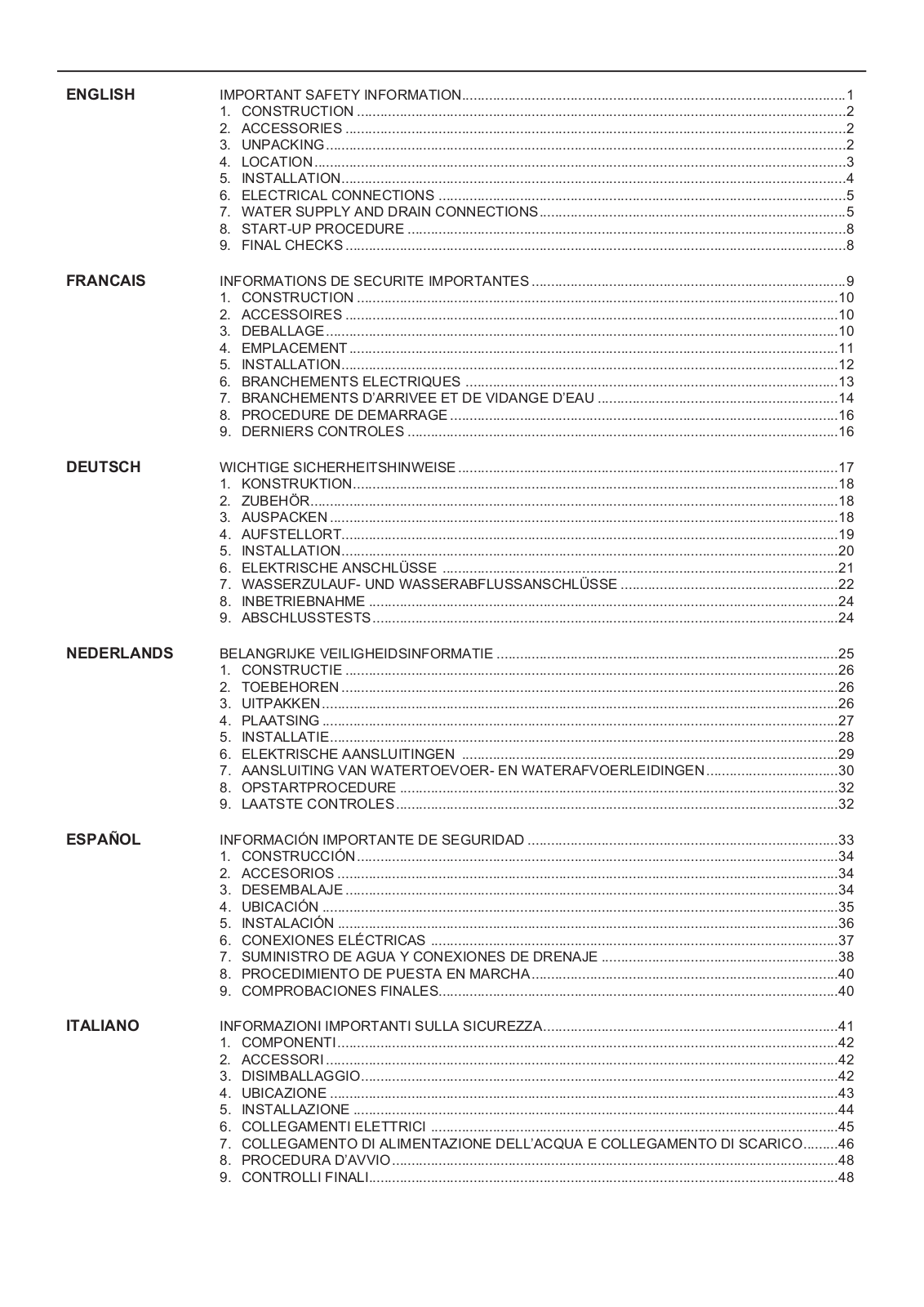
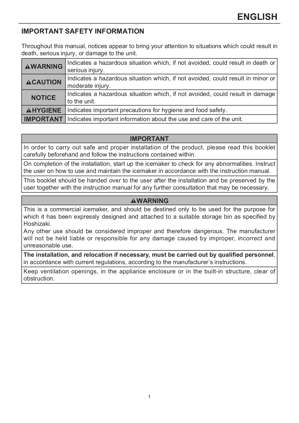
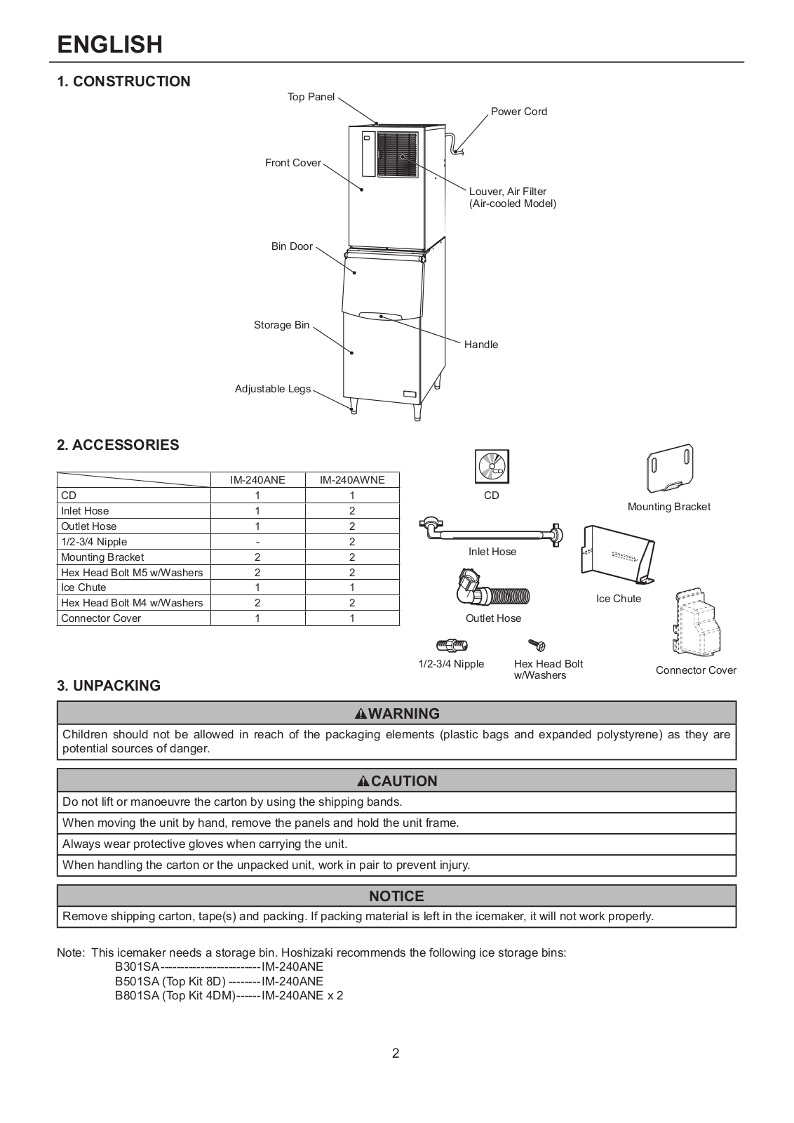
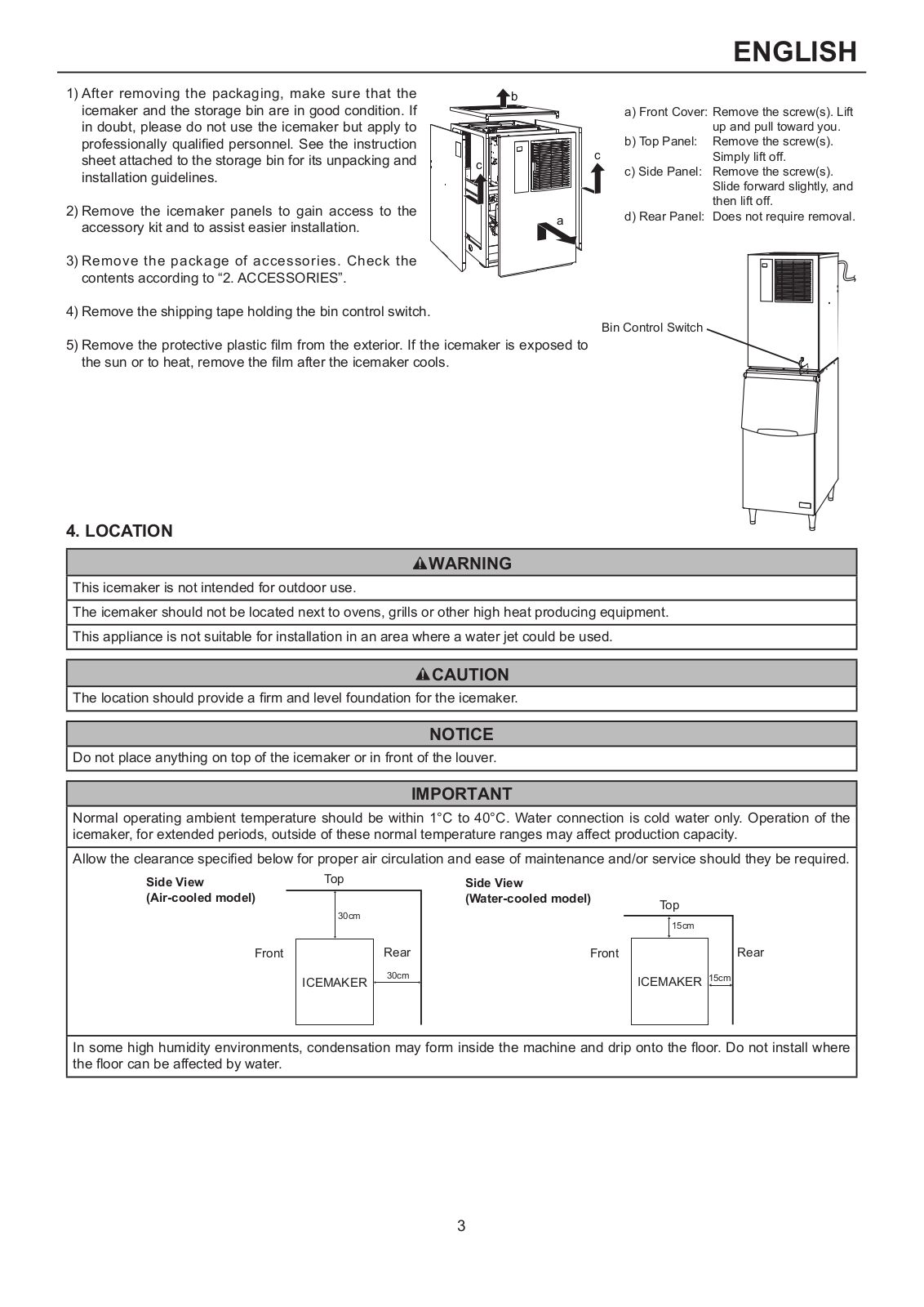
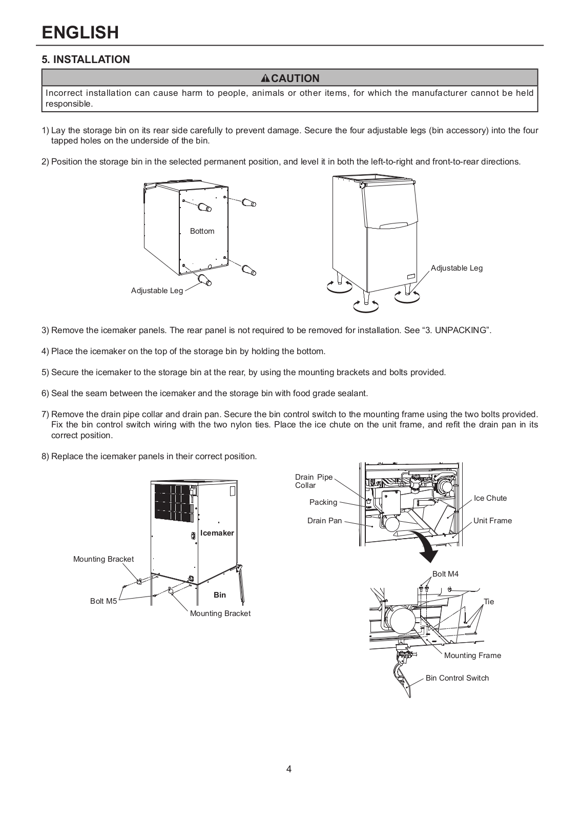
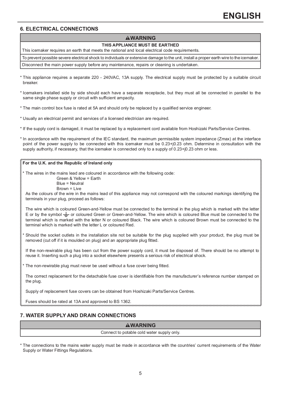
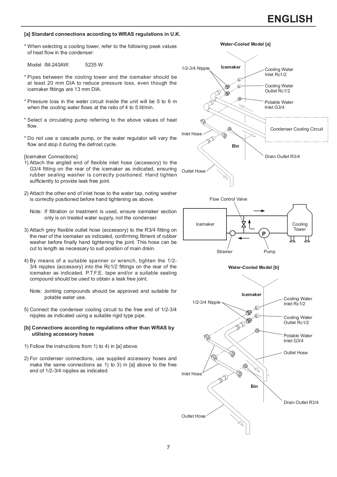
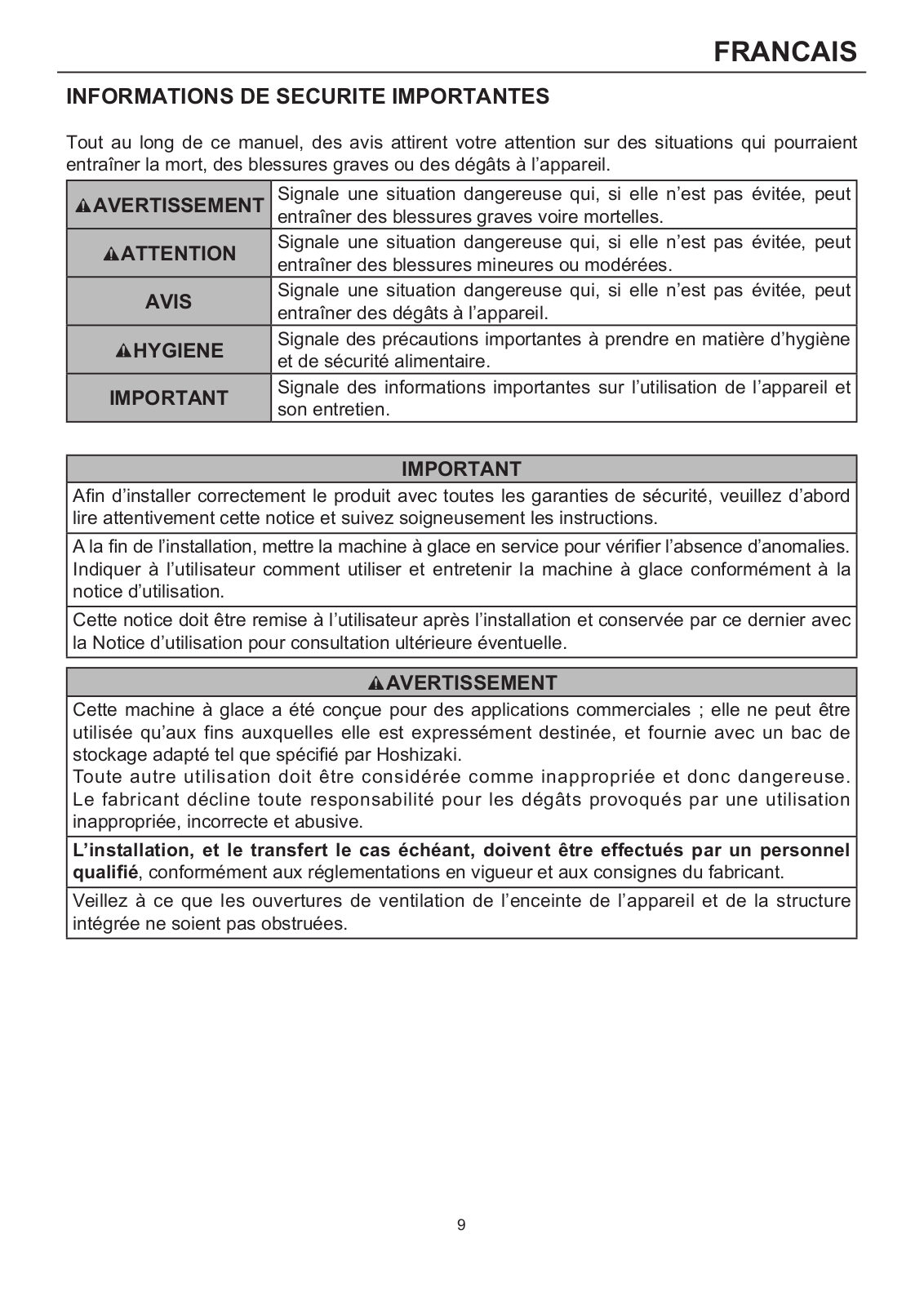
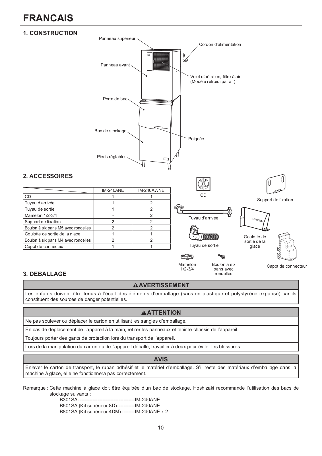
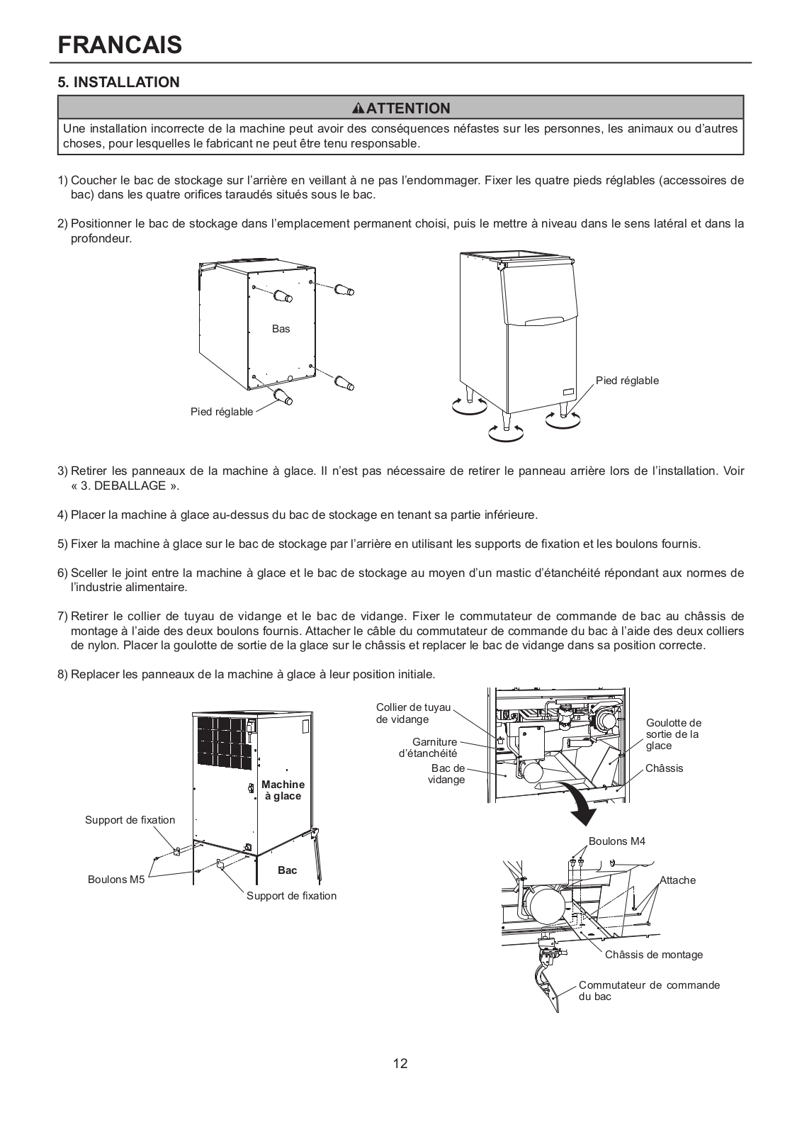
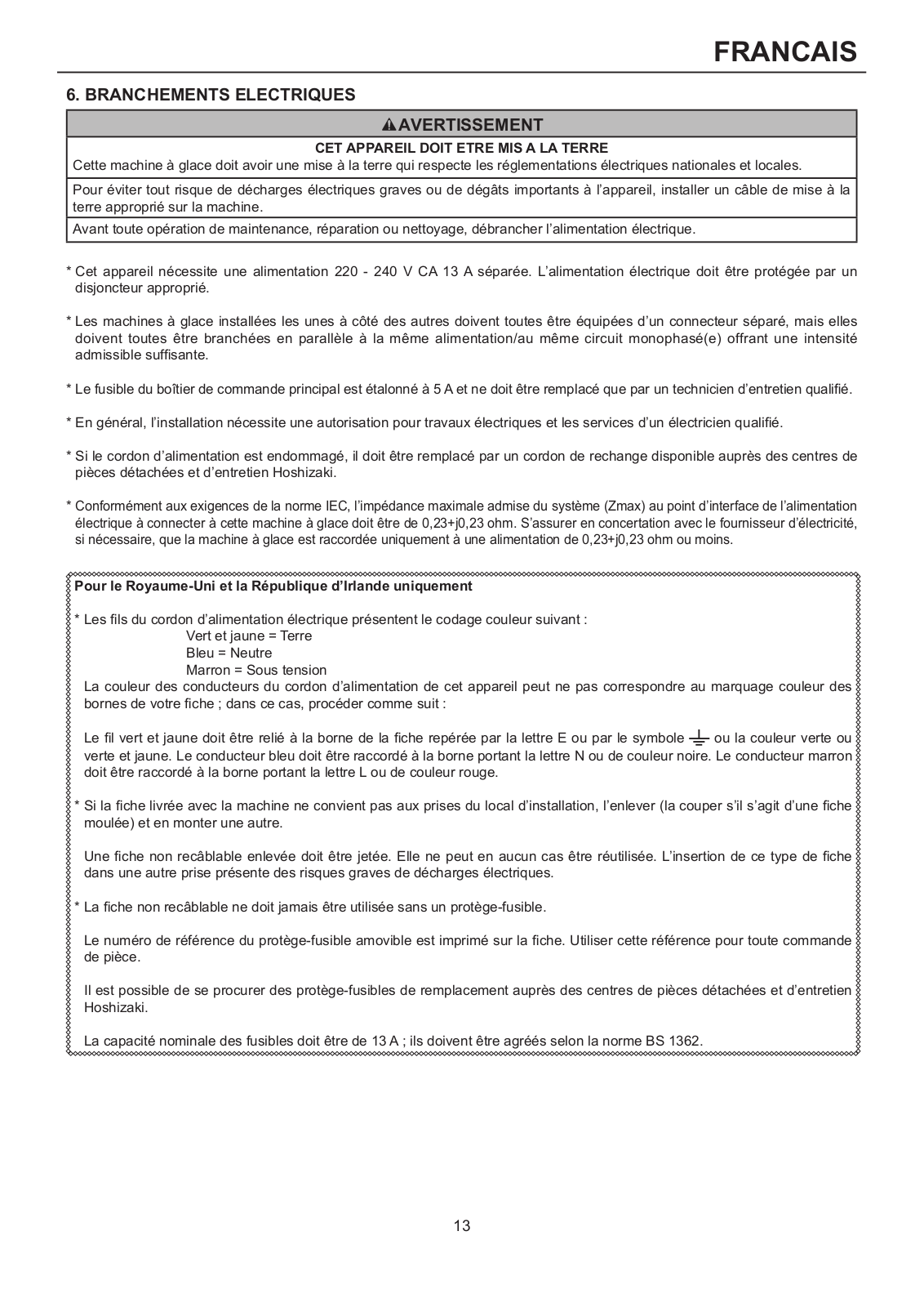
Hoshizaki IM-240AWNE, IM-240ANE INSTALLATION MANUAL
...
Hoshizaki INSTALLATION MANUAL
Download
Specifications and Main Features
Frequently Asked Questions
User Manual
Download
Loading...
+
35
hidden pages
Unhide
You need points to download manuals.
1 point = 1 manual.
You can buy points or you can get point for every manual you upload.
Buy points
Upload your manuals