

Hoshizaki IM-21CNE-HC, IM-30CNE-HC, IM-30CWNE-HC, IM-45CNE-HC, IM-45NE-HC INSTRUCTION MANUAL
...Page 1
SELF-CONTAINED CUBER
MACHINE A GLACONS AUTONOME
STECKERFERTIGER WÜRFELEISBEREITER
IJSBLOKJESMACHINE MET INGEBOUWDE OPSLAGBUNKER
MÁQUINA FABRICADORA DE HIELO INTEGRADA
FABBRICATORE DI GHIACCIO IN CUBETTI A RISERVA INCORPORATA
INSTRUCTION MANUAL
(original instructions)
NOTICE D’UTILISATION
(instructions traduites)
BEDIENUNGSANLEITUNG
(Übersetzung)
GEBRUIKSAANWIJZING
(vertaalde instructies)
MANUAL DE INSTRUCCIONES
(instrucciones traducidas)
IM-21CNE-HC
IM-30CNE-HC
IM-30CWNE-HC
IM-45CNE-HC
IM-45NE-HC
IM-45WNE-HC
IM-65NE-HC
IM-65WNE-HC
IM-100CNE-HC
IM-100NE-HC
IM-100WNE-HC
IM-130NE-HC
IM-130WNE-HC
IM-240NE-HC
IM-240WNE-HC
MANUALE D’ISTRUZIONI
(traduzione)
IM-100NE-HC
Telford 70 Staord Park 7, Telford, Shropshire TF3 3BQ UK
L1M036205 (101520)
Page 2

ENGLISH IMPORTANT SAFETY INFORMATION ...................................................................................................1
I. INSTALLATION INSTRUCTIONS ......................................................................................................3
1. CONSTRUCTION .........................................................................................................................3
2. ACCESSORIES ............................................................................................................................3
3. UNPACKING ................................................................................................................................4
4. LOCATION ...................................................................................................................................5
5. INSTALLATION ............................................................................................................................6
6. ELECTRICAL CONNECTIONS ...................................................................................................6
7. WATER SUPPLY AND DRAIN CONNECTIONS .........................................................................6
II. OPERATING INSTRUCTIONS ..........................................................................................................9
1. START UP ....................................................................................................................................9
2. PREPARING THE ICEMAKER FOR LONG STORAGE ..............................................................9
III. MAINTENANCE ...............................................................................................................................10
1. CLEANING .................................................................................................................................10
2. BEFORE CALLING FOR SERVICE ...........................................................................................11
3. DISPOSAL ..................................................................................................................................12
4. WARRANTY ...............................................................................................................................12
SPECIFICATIONS .................................................................................................................................13
FRANCAIS INFORMATIONS DE SECURITE IMPORTANTES ...............................................................................15
I. CONSIGNES D’INSTALLATION ......................................................................................................17
1. CONSTRUCTION .......................................................................................................................17
2. ACCESSOIRES ..........................................................................................................................17
3. DEBALLAGE ..............................................................................................................................18
4. EMPLACEMENT ........................................................................................................................19
5. INSTALLATION ..........................................................................................................................20
6. BRANCHEMENTS ELECTRIQUES ..........................................................................................20
7. BRANCHEMENTS D’ARRIVEE ET DE VIDANGE D’EAU .........................................................21
. II. CONSIGNES D’UTILISATION .........................................................................................................23
1. MISE EN MARCHE ....................................................................................................................24
2. PREPARATION DU DISTRIBUTEUR DE GLACE EN VUE D’UN ENTREPOSAGE
DE LONGUE DUREE .................................................................................................................24
III. ENTRETIEN .....................................................................................................................................24
1. NETTOYAGE ..............................................................................................................................24
2. AVANT D’APPELER UN REPARATEUR ...................................................................................25
3. MISE AU REBUT ........................................................................................................................26
4. GARANTIE .................................................................................................................................26
SPECIFICATIONS .................................................................................................................................27
DEUTSCH WICHTIGE SICHERHEITSHINWEISE ..................................................................................................30
I. INSTALLATIONSANLEITUNG .........................................................................................................32
1. KONSTRUKTION .......................................................................................................................32
2. ZUBEHÖR ..................................................................................................................................32
3. AUSPACKEN ..............................................................................................................................33
4. AUFSTELLORT ..........................................................................................................................34
5. INSTALLATION ..........................................................................................................................35
6. ELEKTRISCHE ANSCHLÜSSE ................................................................................................35
7. WASSERZUWASSERZULAUF- UND WASSERABFLUSSANSCHLÜSSE ..............................36
II. BEDIENUNGSANLEITUNG .............................................................................................................38
1. INBETRIEBNAHME ....................................................................................................................38
2. MASSNAHMEN FÜR DIE LANGFRISTIGE LAGERUNG DES EISBEREITERS ......................39
III. WARTUNG .......................................................................................................................................39
1. REINIGUNG ...............................................................................................................................39
2. VOR ANRUF DES KUNDENDIENSTES ....................................................................................40
3. ENTSORGUNG ..........................................................................................................................41
4. GEWÄHRLEISTUNG ..................................................................................................................41
TECHNISCHE DATEN ..........................................................................................................................42
Page 3

NEDERLANDS BELANGRIJKE VEILIGHEIDSINFORMATIE ........................................................................................44
I. INSTALLATIE-INSTRUCTIES ..........................................................................................................46
1. CONSTRUCTIE ..........................................................................................................................46
2. TOEBEHOREN ...........................................................................................................................46
3. UITPAKKEN ...............................................................................................................................47
4. PLAATSING ................................................................................................................................48
5. INSTALLATIE .............................................................................................................................49
6. ELEKTRISCHE AANSLUITINGEN ............................................................................................49
7. AANSLUITING VAN WATERTOEVOER- EN WATERAFVOERLEIDINGEN ............................50
II. BEDIENING ......................................................................................................................................52
1. OPSTARTEN ..............................................................................................................................52
2. DE IJSMAKER GEREEDMAKEN VOOR LANGDURIGE OPSLAG ...........................................53
III. ONDERHOUD ..................................................................................................................................53
1. REINIGEN ..................................................................................................................................53
2. VOORDAT U BELT VOOR SERVICE ........................................................................................54
3. VERWIJDERING ........................................................................................................................55
4. GARANTIE .................................................................................................................................55
SPECIFICATIES ....................................................................................................................................56
ESPAÑOL INFORMACIÓN IMPORTANTE DE SEGURIDAD ................................................................................58
I. INSTRUCCIONES DE INSTALACIÓN .............................................................................................60
1. CONSTRUCCIÓN ......................................................................................................................60
2. ACCESORIOS ............................................................................................................................60
3. DESEMBALAJE ..........................................................................................................................61
4. UBICACIÓN ................................................................................................................................62
5. INSTALACIÓN ............................................................................................................................63
6. CONEXIONES ELÉCTRICAS ...................................................................................................63
7. SUMINISTRO DE AGUA Y CONEXIONES DE DRENAJE ........................................................64
II. INSTRUCCIONES DE UTILIZACIÓN ..............................................................................................66
1. PUESTA EN MARCHA ...............................................................................................................66
2. PREPARACIÓN DE LA MÁQUINA DE HIELO PARA UN ALMACENAMIENTO
PROLONGADO ..........................................................................................................................67
III. MANTENIMIENTO ...........................................................................................................................67
1. LIMPIEZA ...................................................................................................................................67
2. ANTES DE LLAMAR AL SERVICIO TÉCNICO ..........................................................................68
3. ELIMINACIÓN ............................................................................................................................69
4. GARANTÍA .................................................................................................................................69
ESPECIFICACIONES ............................................................................................................................70
ITALIANO INFORMAZIONI IMPORTANTI SULLA SICUREZZA ............................................................................72
I. ISTRUZIONI PER L’INSTALLAZIONE .............................................................................................74
1. COMPONENTI ...........................................................................................................................74
2. ACCESSORI ...............................................................................................................................74
3. DISIMBALLAGGIO .....................................................................................................................75
4. UBICAZIONE ..............................................................................................................................76
5. INSTALLAZIONE ........................................................................................................................77
6. COLLEGAMENTI ELETTRICI ...................................................................................................77
7. COLLEGAMENTO DI ALIMENTAZIONE DELL’ACQUA E COLLEGAMENTO DI SCARICO ...78
II. ISTRUZIONI DI FUNZIONAMENTO ................................................................................................80
1. AVVIO .........................................................................................................................................80
2. PREPARATIVI PER IL’IMMAGAZZINAGGIOL DELLA MACCHINA A LUNGO TERMINE .......81
III. MANUTENZIONE .............................................................................................................................81
1. PULIZIA ......................................................................................................................................81
2. PRIMA DI RIVOLGERSI ALL’ASSISTENZA ..............................................................................82
3. SMALTIMENTO ..........................................................................................................................83
4. GARANZIA .................................................................................................................................83
SPECIFICHE .........................................................................................................................................84
Page 4
ENGLISH
IMPORTANT SAFETY INFORMATION
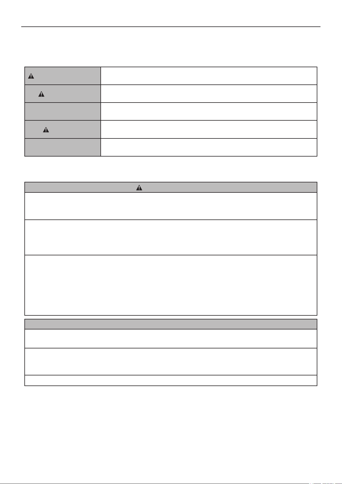
Throughout this manual, notices appear to bring your attention to situations which could result in
death, serious injury, or damage to the unit.
WARNING
CAUTION
NOTICE
HYGIENE
IMPORTANT
This icemaker uses HFC-free refrigerant (propane) that is a non-ozone-depleting and
environmentally sustainable material having very low global warming potential.
Indicates a hazardous situation which, if not avoided, could result in death or
serious injury.
Indicates a hazardous situation which, if not avoided, could result in minor or
moderate injury.
Indicates a hazardous situation which, if not avoided, could result in damage to
the unit.
Indicates important precautions for hygiene and food safety.
Indicates important information about the use and care of the unit.
WARNING
This icemaker contains ammable refrigerant in its cooling unit; installation, handling, servicing
and disposal must therefore only be carried out by authorized technicians.
The refrigerant contained in this icemaker is ammable and sealed in the refrigeration system.
Although the refrigerant does not leak out under normal usage, take utmost care when
handling this icemaker so as not to cause any damages to the system.
In the case of accidental damage to the refrigeration system causing refrigerant leak:
* Do not create a source of ignition in the area.
* Do not operate electrical switches or plugs in the area.
* Do not use naked ame.
* Immediately ventilate the area by opening doors and/or windows.
* Call service engineer.
IMPORTANT
This booklet is an integral and essential part of the product and should be kept and preserved
by the user.
Please read carefully the guidelines and warnings contained herein as they are intended to
provide the installer/user with essential information for the proper installation and the continued
safe use and maintenance of the product.
Please preserve this booklet for any further consultation that may be necessary.
1
Page 5
ENGLISH
WARNING
This is a commercial icemaker, and should be destined only to be used for the purpose for
which it has been expressly designed.
Any other use should be considered improper and therefore dangerous. The manufacturer
will not be held liable or responsible for any damage caused by improper, incorrect and
unreasonable use.
The installation, and relocation if necessary, must be carried out by qualied personnel,
in accordance with current regulations, according to the manufacturer’s instructions.
Keep ventilation openings, in the appliance enclosure or in the built-in structure, clear of
obstruction.
Do not use mechanical devices or other means to accelerate the defrosting process, other
than those recommended by the manufacturer.
The use of any electrical appliance involves the observance of some fundamental rules. In
particular:
* Instances of high humidity and moisture increase the risk of electrical short circuits and
potential electrical shocks. If in doubt, disconnect the icemaker.
* Do not damage the power cord or pull it in order to disconnect the icemaker from the
electrical supply network.
* If the supply cord is damaged, it must be replaced by a replacement cord available from
Hoshizaki Parts/Service Centres.
* Do not touch the electrical parts or operate the switches with damp hands.
* This appliance is not intended for use by persons (including children) with reduced physical,
sensory or mental capabilities, or lack of experience and knowledge, it can however be used
by children aged from 8 years and above and persons with reduced physical, sensory or
mental capabilities, or lack of experience and knowledge providing they have been given
supervision or instruction concerning use of the appliance by a person responsible for their
safety.
* Children shall not play with the appliance.
* Cleaning and user maintenance shall not be made by children without supervision.
* Do not attempt to modify the icemaker. Only qualied personnel may disassemble or repair
the appliance.
2
Page 6
I. INSTALLATION INSTRUCTIONS
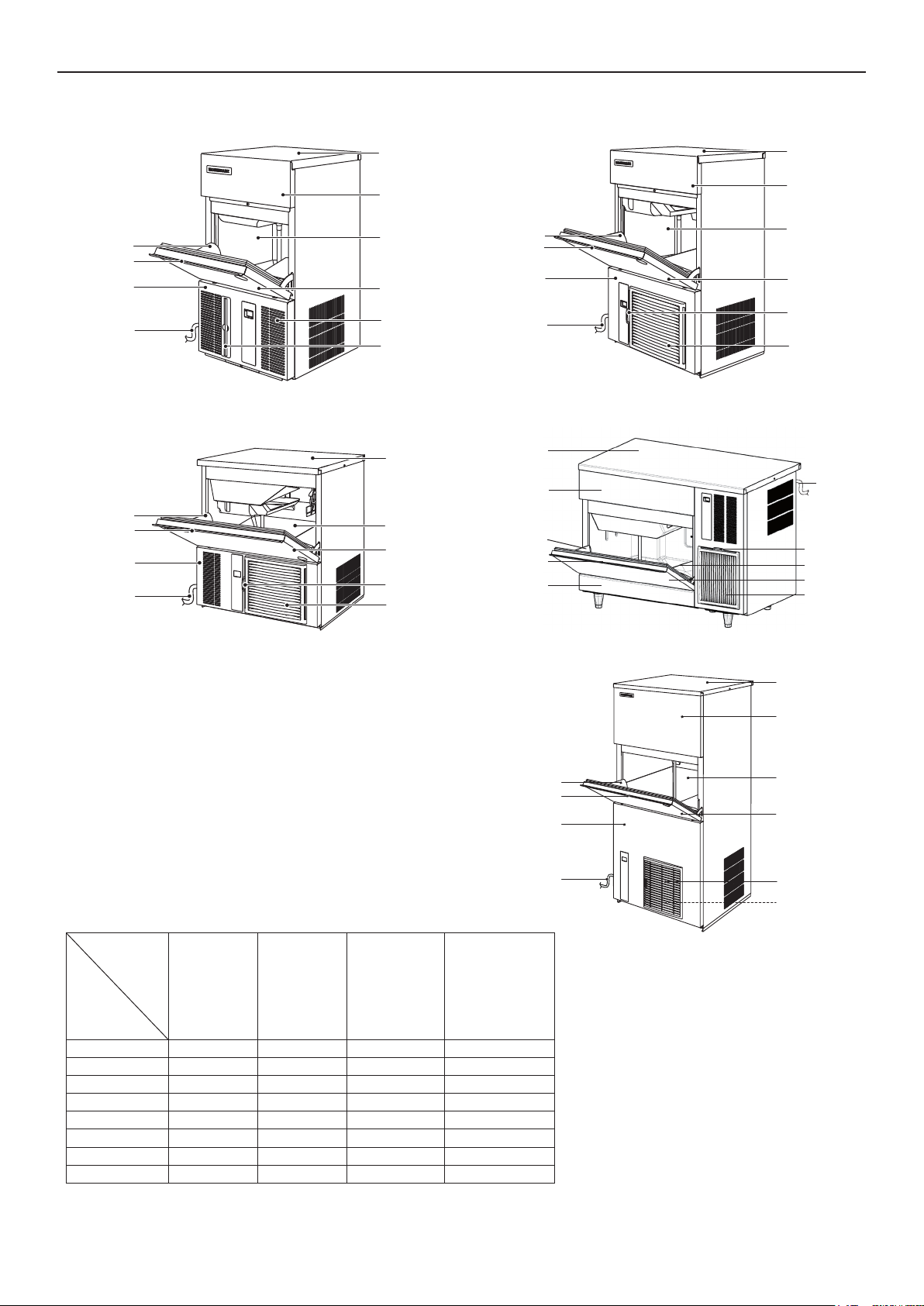
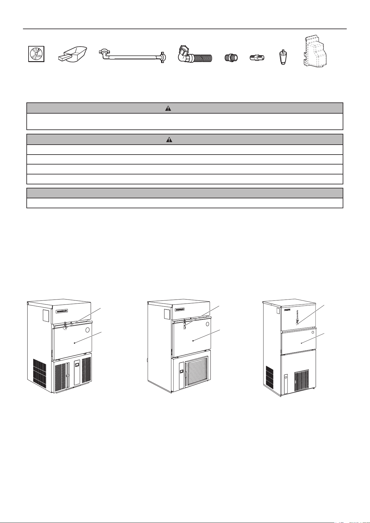
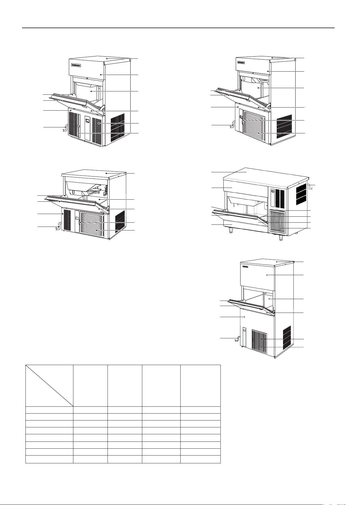
1. CONSTRUCTION
Top Panel
ENGLISH
Top Panel
Slope
Handle
Front Panel
(Lower)
Power Cord
Slope
Handle
Front Panel
(Lower)
Power Cord
[IM-21CNE-HC, 30CNE/CWNE-HC]
Front Panel
(Upper)
Storage Bin
Bin Door
Louver
Air Filter
Top Panel
Storage Bin
Bin Door
Air Filter
Louver
Front Panel
(Upper)
Slope
Handle
Front Panel
(Lower)
Power Cord
[IM-45NE/WNE-HC, 65NE/WNE-HC, 100NE/WNE-HC, 130NE/WNE-HC]
Top Panel
Front Panel
(Upper)
Slope
Handle
Front Panel
(Lower)
Storage Bin
Bin Door
Air Filter
Louver
Power Cord
Air Filter
Storage Bin
Bin Door
Louver
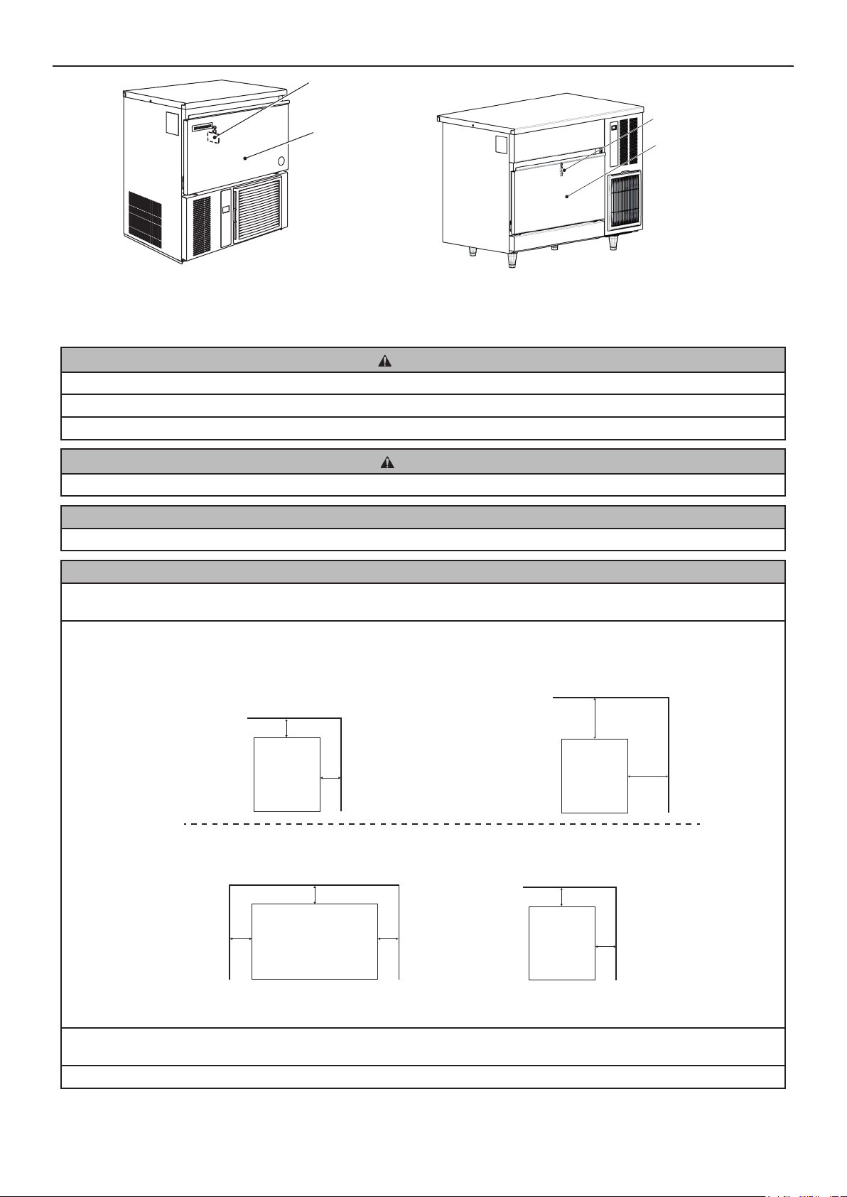
[IM-45CNE-HC]
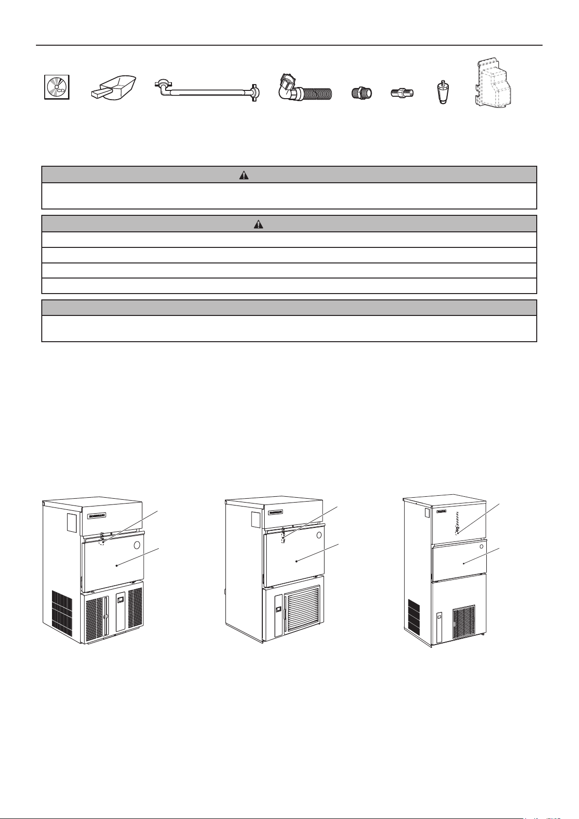
2. ACCESSORIES
IM-30CNE-HC
IM-45CNE-HC
IM-21CNE-HC
CD 1 1 1 1
Scoop 1 1 1 1
Inlet Hose 1 1 1 2
Outlet Hose 1 1 1 2
1/2-3/4 Nipple - - - 2
Leg
Connector Cover 1 1 1 1
3/4-3/4 Nipple - - 1 -
- 4 5 4
IM-45NE-HC
IM-65NE-HC
IM-100NE-HC
IM-130NE-HC
IM-240NE-HC
IM-100CNE-HC
IM-30CWNE-HC
IM-45WNE-HC
IM-65WNE-HC
IM-100WNE-HC
IM-130WNE-HC
IM-240WNE-HC
Slope
Handle
Front Panel
(Lower)
Power Cord
[IM-100CNE-HC]
Top Panel
Front Panel
(Upper)
Storage Bin
Bin Door
Louver
Air Filter
[IM-240NE/WNE-HC]
3
Page 7
ENGLISH
CD Inlet Hose Leg Connector CoverScoop 1/2-3/4
Outlet Hose
3/4-3/4
Nipple
Nipple
3. UNPACKING
WARNING
Children should not be allowed in reach of the packaging elements (plastic bags and expanded polystyrene) as they are
potential sources of danger.
CAUTION
Do not lift or manoeuvre the carton by using the shipping bands.
When moving the unit by hand, hold the unit bottom.
Always wear protective gloves when carrying the unit.
When handling the carton or the unpacked unit, work in pairs to prevent injury.
NOTICE
Remove shipping carton, tape(s) and packing. If packing material is left in the icemaker, it will not work properly.
1) After removing the packaging, make sure that the icemaker is in good condition. If in doubt, please do not use the icemaker
but apply to professionally qualied personnel.
2) Remove the shipping tape holding the door and front panel.
3) Remove the protective plastic lm from the exterior. If the icemaker is exposed to the sun or to heat, remove the lm after the
icemaker cools.
4) Remove the package of accessories. Check the contents according to “2. ACCESSORIES”.
5) Remove the shipping tape holding the bin control switch by opening the bin door and reaching in.
Bin Control
Switch
Bin Door
[IM-240NE/WNE-HC]
[IM-21CNE-HC, 30CNE/CWNE-HC]
Bin Control
Switch
Bin Door
[IM-45NE/WNE-HC, 65NE/WNE-HC,
100NE/WNE-HC, 130NE/WNE-HC]
Bin Control
Switch
Bin Door
4
Page 8
Bin Control
Switch
Bin Door
ENGLISH
Bin Control
Switch
Bin Door
[IM-45CNE-HC]
[IM-100CNE-HC]
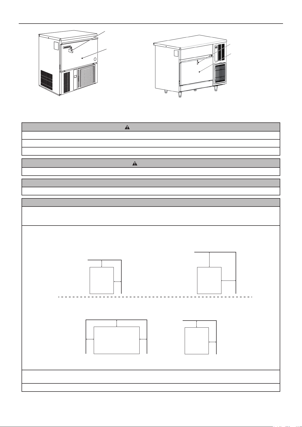
4. LOCATION
WARNING
This icemaker is not intended for outdoor use.
The icemaker should not be located next to ovens, grills or other high heat producing equipment.
This appliance is not suitable for installation in an area where a water jet could be used.
CAUTION
The location should provide a rm and level foundation for the icemaker.
NOTICE
Do not place anything on top of the icemaker or in front of the louver.
IMPORTANT
Normal operating ambient temperature should be within 1°C to 40°C. Water connection is cold water only. Operation of the
icemaker, for extended periods, outside of these normal temperature ranges may aect production capacity.
Allow the clearance specied below for proper air circulation and ease of maintenance and/or service should they be required.
[IM-21CNE-HC, 30CNE/CWNE-HC, 45CNE-HC, 240WNE-HC]
Side View
Front
* No clearance required on sides
Top
15cm
Rear
ICEMAKER
15cm
[IM-240NE-HC]
Side View
* No clearance required on sides
Top
30cm
Front
ICEMAKER
Rear
30cm
[IM-45NE/WNE-HC, 65NE/WNE-HC, 100CNE-HC, 100NE/WNE-HC, 130NE/WNE-HC]
Top View
Left
15cm
Rear
15cm
ICEMAKER
Front
Right
15cm
Side View
Front
Top
15cm
ICEMAKER
Rear
15cm
In some high humidity environments, condensation may form inside the machine and drip onto the oor. Do not install where
the oor can be aected by water.
Avoid prolonged exposure of the appliance to direct sunlight.
5
Page 9
ENGLISH
5. INSTALLATION
CAUTION
Incorrect installation can cause harm to people, animals or other items, for which the manufacturer cannot be held
responsible.
* Place the icemaker in the selected permanent site.
[Except IM-21CNE-HC]
* When attaching the adjustable legs (accessory), level the unit in both the left-to-right and front-to-rear directions.
6. ELECTRICAL CONNECTIONS
WARNING
THIS APPLIANCE MUST BE EARTHED
This icemaker requires an earth that meets the national and local electrical code requirements.
To prevent possible severe electrical shock to individuals or extensive damage to the unit, install a proper earth wire to the icemaker.
Disconnect the main power supply before any maintenance, repairs or cleaning is undertaken.
* This appliance requires a separate 220 - 240VAC, 10A [IM-21CNE-HC, 30CNE/CWNE-HC, 45CNE/NE/WNE-HC, 65NE/WNE-
HC, 100CNE/NE/WNE-HC, 130NE/WNE-HC] / 13A [IM-240NE/WNE-HC] supply. The electrical supply must be protected by a
suitable circuit breaker.
* The main control box fuse is rated at 5A and should only be replaced by a qualied service engineer.
* Usually an electrical permit and services of a licensed electrician are required.
For the U.K. and the Republic of Ireland only
* The wires in the mains lead are coloured in accordance with the following code:
Green & Yellow = Earth
Blue = Neutral
Brown = Live
As the colours of the wire in the mains lead of this appliance may not correspond with the coloured markings identifying the
terminals in your plug, proceed as follows:
The wire which is coloured Green-and-Yellow must be connected to the terminal in the plug which is marked with the letter
E or by the symbol
terminal which is marked with the letter N or coloured Black. The wire which is coloured Brown must be connected to the
terminal which is marked with the letter L or coloured Red.
* Should the socket outlets in the installation site not be suitable for the plug supplied with your product, the plug must be
removed (cut o if it is moulded on plug) and an appropriate plug tted.
If the non-rewirable plug has been cut from the power supply cord, it must be disposed of. There should be no attempt to
reuse it. Inserting such a plug into a socket elsewhere presents a serious risk of electrical shock.
* The non-rewirable plug must never be used without a fuse cover being tted.
or coloured Green or Green-and-Yellow. The wire which is coloured Blue must be connected to the
The correct replacement for the detachable fuse cover is identiable from the manufacturer’s reference number stamped on
the plug.
Supply of replacement fuse covers can be obtained from Hoshizaki Parts/Service Centres.
Fuses should be rated at 13A and approved to BS 1362.
7. WATER SUPPLY AND DRAIN CONNECTIONS
WARNING
Connect to potable cold water supply only.
6
Page 10
ENGLISH
* The connections to the mains water supply must be made in accordance with the countries’ current requirements of the Water
Supply or Water Fittings Regulations.
* Icemaking water must be potable water. Where scaling can be caused by water quality:
- Installation of an external lter or softener is recommended. Contact your local water treatment professional or Hoshizaki
service agent.
- Change to the “full drain ush” mode is recommended. Contact your local Hoshizaki service agent.
* Water supply pressure should be minimum 0.07 MPa (0.7 bar) and maximum 0.8 MPa (8 bar). If the pressure exceeds 0.8
MPa (8 bar), use a proper pressure reducing valve. Do NOT throttle back the supply tap.
* A plumbing permit and services of a licensed plumber may be required in some areas.
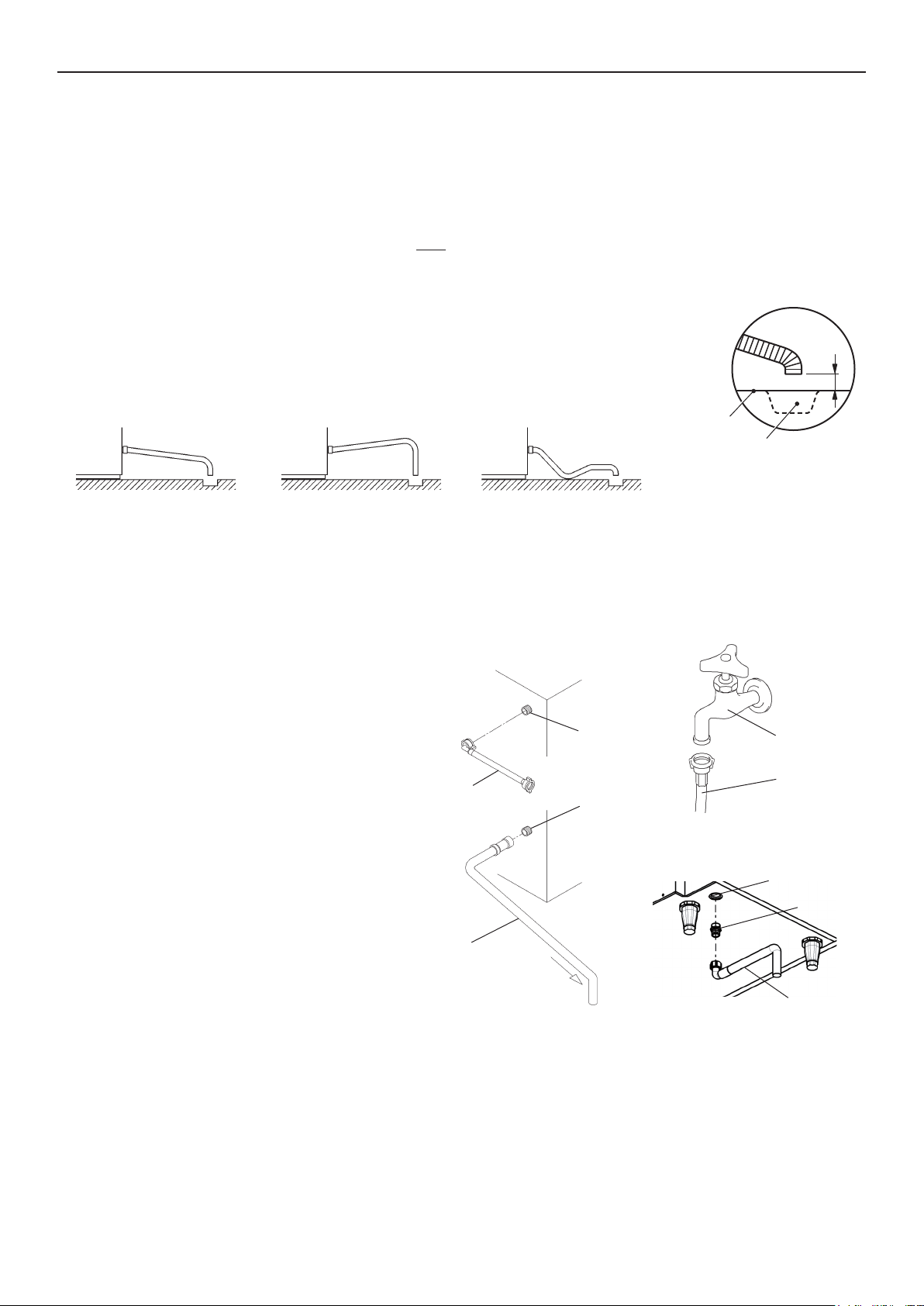
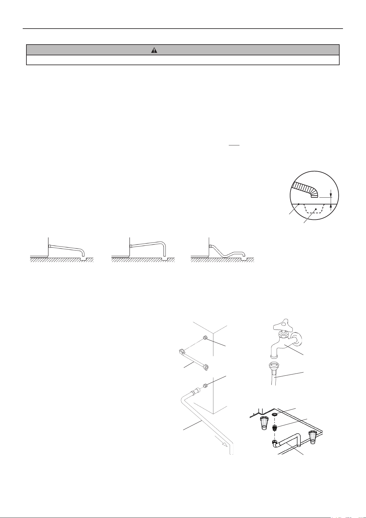
* The icemaker drain is gravity ow, so ensure drain hose has an adequate pitch or fall.
* Drain lines should not be installed directly to the sewer system. A vertical air gap of a minimum of 5
cm should be between the end of the drain hoses from the icemaker and the oor drain.
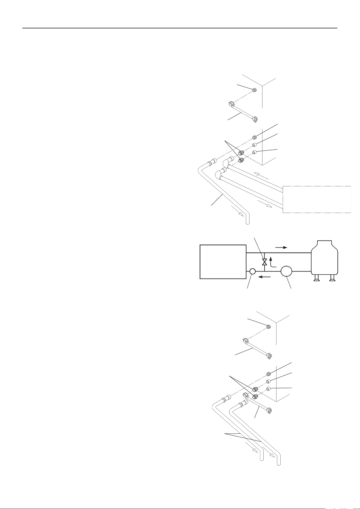
* To prevent a backow into the storage bin, the outlet hose must be laid as shown.
GOOD BAD
Downgrade
Upgrade
BAD
Floor
5cm air gap
Drain
* On water-cooled model, a back ow preventer may be required in the cooling water circuit.
* Be sure to use the new hose-sets supplied with the appliance. Do not reuse any old hose-sets.
[Air-Cooled Model]
1) Attach the angled end of flexible inlet hose
(accessory) to the G3/4 tting on the rear of the
Air-Cooled Model
icemaker as indicated, ensuring rubber sealing
washer is correctly positioned. Hand tighten
suciently to provide leak free joint.
2) Attach the other end of inlet hose to the water tap,
noting washer is correctly positioned before hand
Potable Water
Inlet G3/4
tightening as above. It is a wise precaution to
have a stop valve within easy reach.
3) [Except IM-100CNE-HC]
Inlet Hose
Drain Outlet R3/4
Hand tighten grey exible outlet hose (accessory)
onto the R3/4 tting on the rear of the icemaker
as indicated, ensuring rubber washer is correctly
positioned to obtain a leak free joint. The hose
can be cut to length as necessary to suit position
of main drain.
[IM-100CNE-HC]
Outlet Hose
By means of a suitable spanner or wrench, tighten
the 3/4-3/4 nipple (accessory) into the Rc3/4
tting on the bottom of the icemaker as indicated.
P.T.F.E. tape and/or a suitable sealing compound
should be used to obtain a leak free joint.
Water Supply Tap
Inlet Hose
IM-100CNE-HC
Drain Outlet Rc3/4
3/4-3/4 Nipple
Outlet Hose
Note: Jointing compounds should be approved and suitable for potable water use.
Hand tighten grey exible outlet hose (accessory) onto the 3/4-3/4 nipple as indicated, ensuring rubber washer is correctly
positioned to obtain a leak free joint. The hose can be cut to length as necessary to suit position of main drain.
7
Page 11
ENGLISH
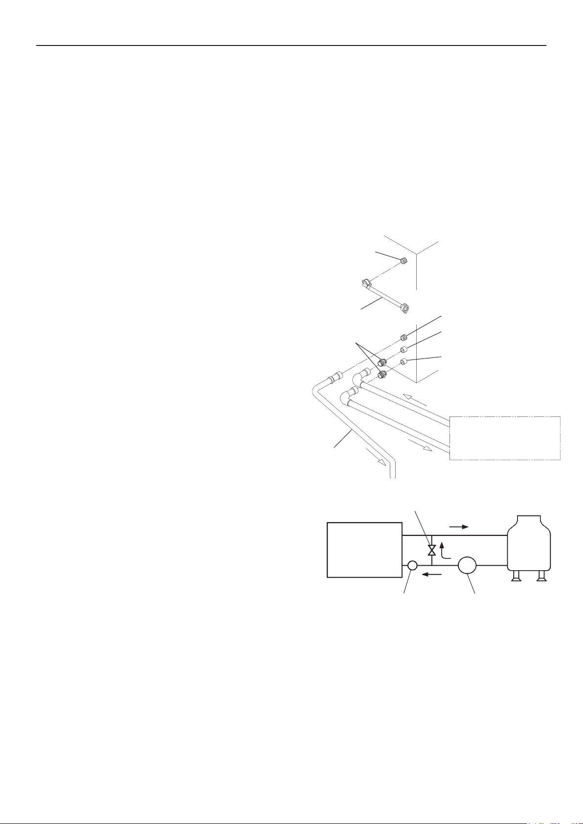
[Water-Cooled Model]
* Hoshizaki recommends that the water-cooled condenser should be connected to a closed circuit recirculating type cooling
system utilizing a tower, water chiller or similar. Water make up should be via a ball valve/break tank arrangement.
* Whilst connecting a water-cooled condenser to a mains water
(potable) supply will not aect the performance of the machine, it
will most certainly cause a high use/waste of a valuable resource
and is not recommended.
* The services of a licensed or coded plumber should be used to
ensure a correct installation.
* The connections should be made properly in compliance with the
applicable national or local regulations.
[a] Standard connections according to WRAS regulations in U.K.
* When selecting a cooling tower, refer to the following peak values of
heat ow in the condenser:
Model IM-30CW/45W: 295-760W
IM-65W: 875W
IM-100/130W: 1165W
IM-240W: 5235W
* Pipes between the cooling tower and the icemaker should be at
least 20 mm DIA to reduce pressure loss, even though the icemaker
ttings are 13 mm DIA.
* Pressure loss in the water circuit inside the unit will be 5 to 6 m
when the cooling water ows at the ratio of 4 to 5 lit/min.
Potable Water
Inlet G3/4
Inlet Hose
1/2-3/4 Nipple
Outlet Hose
Water-Cooled Model [a]
Drain Outlet R3/4
Cooling Water
Inlet Rc1/2
Cooling Water
Outlet Rc1/2
Condenser Cooling Circuit
Flow Control Valve
* Select a circulating pump referring to the above values of heat ow.
* Do not use a cascade pump, or the water regulator will vary the ow
and stop it during the defrost cycle.
[Icemaker Connections]
1) Attach the angled end of exible inlet hose (accessory) to the G3/4
fitting on the rear of the icemaker as indicated, ensuring rubber
sealing washer is correctly positioned. Hand tighten suciently to
provide leak free joint.
2) Attach the other end of inlet hose to the water tap, noting washer is
correctly positioned before hand tightening as above.
Note: If filtration or treatment is used, ensure icemaker section
only is on treated water supply, not the condenser.
3) Attach grey exible outlet hose (accessory) to the R3/4 tting on
the rear of the icemaker as indicated, conrming tment of rubber
washer before nally hand tightening the joint. The hose can be cut
to length as necessary to suit position of main drain.
4) By means of a suitable spanner or wrench, tighten the 1/2-
3/4 nipples (accessory) into the Rc1/2 fittings on the rear of the
icemaker as indicated. P.T.F.E. tape and/or a suitable sealing
compound should be used to obtain a leak free joint.
Note: Jointing compounds should be approved and suitable for
potable water use.
Icemaker Cooling
Tower
P
Strainer Pump
Water-Cooled Model [b]
Potable Water
Inlet G3/4
Inlet Hose
Drain Outlet R3/4
1/2-3/4 Nipple
Inlet Hose
Outlet Hose
Cooling Water
Inlet Rc1/2
Cooling Water
Outlet Rc1/2
5) Connect the condenser cooling circuit to the free end of 1/2-3/4
nipples as indicated using a suitable rigid type pipe.
8
Page 12
ENGLISH
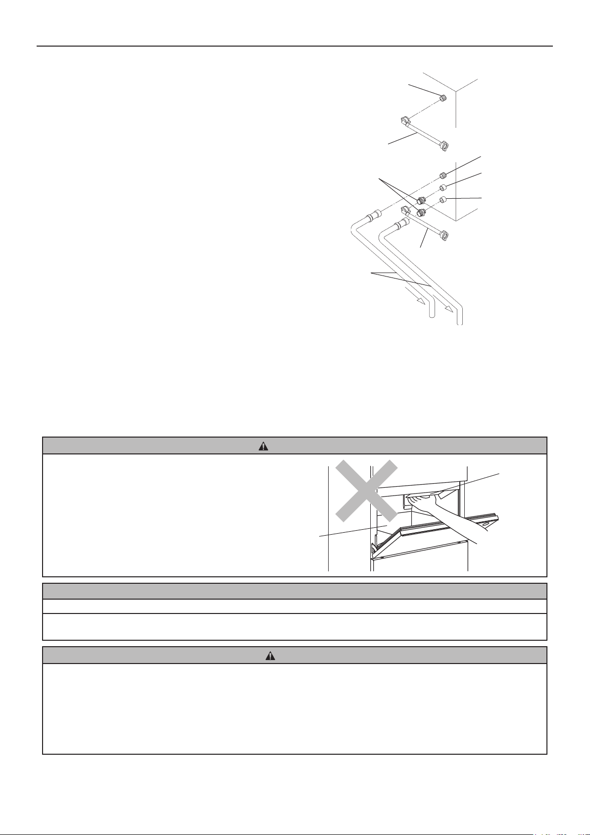
[b] Connections according to regulations other than WRAS by utilising accessory hoses
1) Follow the instructions from 1) to 4) in [a] above.
2) For condenser connections, use supplied accessory hoses and make the same connections as 1) to 3) in [a] above to the free
end of 1/2-3/4 nipples as indicated.
II. OPERATING INSTRUCTIONS
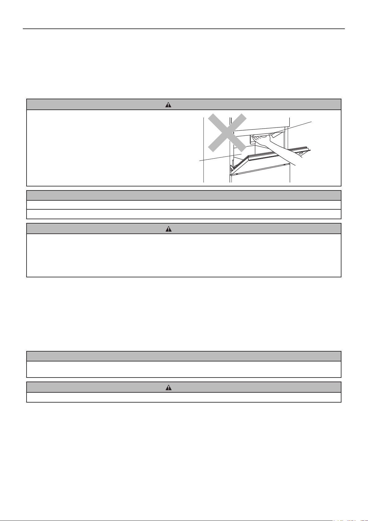
CAUTION
Do not put your hands into the back of the storage bin or the ice
chute on top of the storage bin. Ice may drop o the icemaker,
a hard block of ice may suddenly break down, or the icemaking
mechanism may suddenly move, resulting in injury.
Storage Bin
NOTICE
All parts are factory-adjusted. Improper adjustments may result in failure.
If the unit is turned o, wait for at least 3 minutes before restarting the icemaker to prevent damage to the compressor.
Ice Chute
HYGIENE
This icemaker is designed to produce edible ice. To keep the icemaker hygienic:
* Wash your hands before removing ice. Use the plastic scoop provided (accessory).
* The storage bin is for ice use only. Do not store anything else in the bin nor use other electrical appliances in the bin.
* Clean the storage bin before use (see “III. 1. CLEANING”).
* Keep the scoop clean. Clean it by using a neutral cleaner and rinse thoroughly.
* Close the door after removing ice to prevent entrance of dirt, dust or insects into the storage bin.
1. START UP
The installer will normally commission the icemaker to start the automatic icemaking process. To ensure continuous operation,
make sure that:
* The water supply tap is on, and
* The icemaker is connected to the power supply.
2. PREPARING THE ICEMAKER FOR LONG STORAGE
NOTICE
This icemaker will not work at subfreezing temperatures. To prevent damage to the water supply line, drain the icemaker when
air temperature is below zero.
HYGIENE
When shutting down the icemaker for two or more days, drain the icemaker to prevent contamination in the water circuit.
1) Unplug the icemaker or disconnect the power supply.
2) Close the water supply tap, and remove the inlet hose.
3) Remove all ice from the storage bin, and clean the bin.
4) Ask for draining of the icemaker by professional qualied personnel.
9
Page 13
ENGLISH
III. MAINTENANCE
1. CLEANING
WARNING
Before carrying out any cleaning or maintenance operations, unplug the icemaker from the electrical supply network.
This appliance must not be cleaned by use of a water jet.
CAUTION
When using a neutral cleaner or sodium hypochlorite, thoroughly read and understand the instructions provided to prevent
potential health problems.
NOTICE
Ask a trained service person to clean and sanitise the icemaker water system at least twice a year and to check and clean the
condenser at least once a year.
To prevent possible damage, do not clean the plastic parts with water above 40°C or in a dishwasher.
[a] Machine and Bin Exterior
Wipe the exterior at least once per week with a clean, soft cloth. Use a damp cloth containing a neutral cleaner to wipe o
grease or dirt.
[b] Scoop and Storage Bin Handle Cleaning/Sanitisation (Daily)
1) Either mix 1 litre of water with 4 ml of 5.25% sodium hypochlorite solution in a suitable container, or the recommended
Hoshizaki sanitiser as directed.
2) Soak the scoop in the solution for more than 3 minutes. Rinse thoroughly, and shake to remove surplus liquid.
Note: Using a cloth to dry may re-contaminate.
3) Use a neutral cleaner to wash the storage bin handle. Rinse thoroughly.
4) Soak a clean cloth with the sanitising solution, and wipe the handle. Use fresh water and a clean cloth to rinse/dry.
[c] Storage Bin Interior Cleaning/Sanitisation (Weekly)
1) Open the storage bin door, and remove all ice.
2) Wash the bin liner with a neutral non-abrasive cleaner. Rinse thoroughly.
3) Soak a clean cloth with the neutral cleaner, and wipe both sides of the slope and the door inner surface. Wipe o the cleaner
with a clean damp cloth.
4) Either mix 5 litres of water with 18 ml of 5.25% sodium hypochlorite solution in a suitable container, or the recommended
Hoshizaki sanitiser as directed.
5) Soak a clean sponge or cloth with the solution, and wipe the bin liner, bin door and slope.
6) The remaining solution can be used to sanitise utensils.
Note: Do not wipe dry or rinse after sanitising, but allow to air dry.
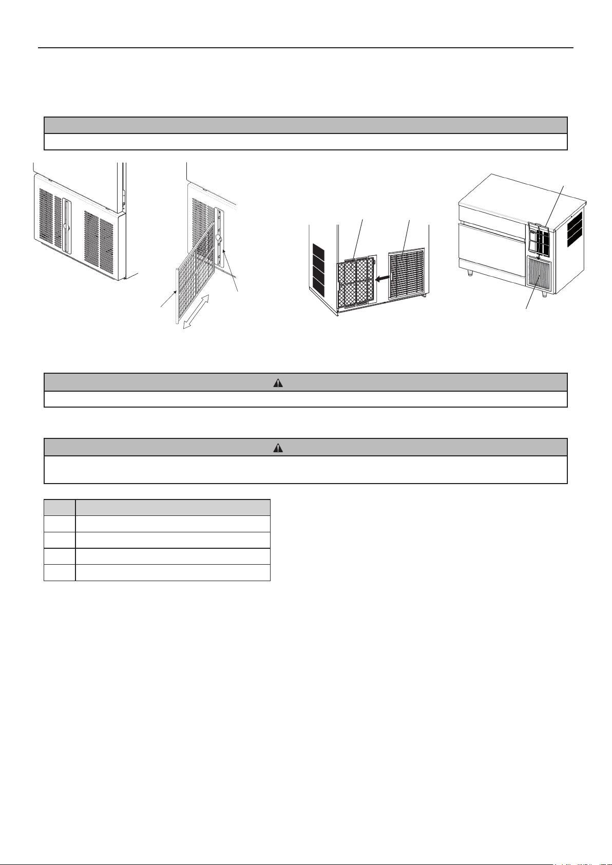
[d] Air Filter (Air-Cooled Model Only)
Plastic mesh air lters remove dirt or dust from the air, and keep the condenser from getting clogged. If the lters get clogged,
the icemaker’s performance will be reduced. Remove and clean the air lter(s) at least twice per month:
1) Slide the air lter o the lter guide [IM-21CNE/30CNE-HC] or the louver [IM-45CNE/45NE/65NE/100CNE/100NE/130NE/240
NE-HC].
10
Page 14
ENGLISH
2) Clean the air lter by using a vacuum cleaner. When severely clogged, use warm water and a neutral cleaner to wash the air
lter.
3) Rinse and dry the air lter thoroughly.
NOTICE
After cleaning, be sure to place the air lter back in position.
Air Filter
Air Filter
[IM-21CNE/30CNE-HC]
Air Filter
Filter Guide
Slide in/out
[IM-45CNE/45NE/65NE/100NE/130NE/240NE-HC]
Louver
Louver
[IM-100CNE-HC]
2. BEFORE CALLING FOR SERVICE
WARNING
Do not damage the refrigerant circuit.
[a] Error Code Indication
WARNING
If the error code “E” is indicated on the display, there is a possibility of gas leaks. Do not touch the unit. Ventilate the area and
immediately call for service.
Code Possible Cause
E1 Freeze error.
E2 Defrost error.
EE Other error.
EF Gas sensor (if provided) detects gas leaks.
[b] No Error Code Indication
If the icemaker does not work properly or does not work at all and no error code is indicated on the display, before calling for
service, check that:
* The power is supplied to the unit.
* The water is turned on.
* The air lter is clean (air-cooled model).
* The cooling water circuit has a proper ow (water-cooled model).
For further assistance or advice, contact your local Hoshizaki service agent.
[c] Alarm Code Indication
If the alarm code A1 or A2 appears, the gas sensor may be defective. Contact your local Hoshizaki service agent.
11
Page 15

ENGLISH
3. DISPOSAL
Comply with local regulations regarding disposal of this appliance and its refrigerant gas. Before you scrap the appliance, take
o the door to prevent children trapped.
Correct disposal of this product:
This marking indicates that this product should not be disposed with other household wastes throughout the EU. To
prevent possible harm to the environment or human health from uncontrolled waste disposal, recycle it responsibly
to promote the sustainable reuse of material resources. To return your used device, use the return and collection
systems or contact the retailer where the product was purchased. They can take this product for environmental safe
recycling.
4. WARRANTY
Hoshizaki warrants to the original owner/user that all Hoshizaki branded products shall be free of defects in material and/or
workmanship for the duration of the “warranty period”. The warranty shall be eective for two years from the date of installation.
Hoshizaki’s liability under the terms of the warranty are limited and shall exclude routine servicing, cleaning, essential
maintenance and/or repairs occasioned by misuse and installations not in accordance with Hoshizaki guidelines.
Warranty repairs should be completed by an approved Hoshizaki dealer or service agency using genuine Hoshizaki components.
To obtain full details of your warranty and approved service agency, please contact your dealer/supplier, or the nearest Hoshizaki
Service oce:
Europe, Middle East, Africa
Hoshizaki UK - UK, Ireland
TEL: +44 845 456 0585
FAX: +44 132 283 8331
uksales@hoshizaki.co.uk
Hoshizaki Deutschland - Germany, Switzerland, Austria
TEL: +49 2154 92810
FAX: +49 2154 928128
info@hoshizaki.de
Hoshizaki France - France
TEL: +33 1 48 63 93 80
FAX: +33 1 48 63 93 88
info@hoshizaki.fr
Hoshizaki Iberia - Spain, Portugal
TEL: +34 93 478 09 52
FAX: +34 93 478 08 00
info@hoshizaki.es
Asia, Oceania
Hoshizaki Singapore
TEL: +65 6225 2612
FAX: +65 6225 3219
Hoshizaki Middle East - Middle East
TEL: +971 48 876 612
FAX: +971 48 876 613
sales@hoshizaki.ae
Hoshizaki Benelux - Netherlands, Belgium, Luxembourg
TEL: +31 85 018 83 70
info@hoshizaki.nl
Hoshizaki Italia - Italy
TEL: +39 344 0616467
TEL: +39 348 3022156
info@hoshizaki.it
Hoshizaki Europe B.V. - all other countries within Europe
and Africa
TEL: +31 20 6918499
FAX: +31 20 6918768
sales@hoshizaki.nl
Hoshizaki Hong Kong
TEL: +852 2866-2108
FAX: +852 2866-2109
Hoshizaki Taiwan
TEL: +886 2 2706 8818
FAX: +886 2 2708 7999
Hoshizaki Lancer
TEL: +61 8 8268 1388
FAX: +61 8 8268 1978
12
Page 16
ENGLISH
SPECIFICATIONS
Model IM-21CNE-HC IM-30CNE-HC IM-45CNE-HC
Type Air-cooled, cube ice Air-cooled, cube ice Air-cooled, cube ice
Power Supply 1 phase 220 - 240V 50Hz 1 phase 220 - 240V 50Hz 1 phase 220 - 240V 50Hz
Electric Consumption 225W 230W 275W
Ice Production per 24h 23kg (5mm) / 25kg (15mm)
Dimensions 398mm(W) x 451mm(D) x
Refrigerant R290, 55g R290, 65g R290, 70g
Insulation Foam Blowing
Agent
Weight Net: 34kg (Gross: 39kg) Net: 34kg (Gross: 39kg) Net: 45kg (Gross: 55kg)
Ambient Temp 1 - 40°C 1 - 40°C 1 - 40°C
Water Supply Temp 5 - 35°C 5 - 35°C 5 - 35°C
Water Supply Pressure 0.07 - 0.8 MPa (0.7 - 8 bar) 0.07 - 0.8 MPa (0.7 - 8 bar) 0.07 - 0.8 MPa (0.7 - 8 bar)
Voltage Range Rated voltage ± 6% Rated voltage ± 6% Rated voltage ± 6%
Model IM-45NE-HC IM-65NE-HC IM-100CNE-HC
Type Air-cooled, cube ice Air-cooled, cube ice Air-cooled, cube ice
Power Supply 1 phase 220 - 240V 50Hz 1 phase 220 - 240V 50Hz 1 phase 220 - 240V 50Hz
Electric Consumption 275W 320W 500W
Ice Production per 24h 40kg (5mm) / 46kg (15mm)
Dimensions 503mm(W) x 456mm(D) x
Refrigerant R290, 70g R290, 110g R290, 125g
Insulation Foam Blowing
Agent
Weight Net: 44kg (Gross: 50kg) Net: 50kg (Gross: 60kg) Net: 77kg (Gross: 88kg)
Ambient Temp 1 - 40°C 1 - 40°C 1 - 40°C
Water Supply Temp 5 - 35°C 5 - 35°C 5 - 35°C
Water Supply Pressure 0.07 - 0.8 MPa (0.7 - 8 bar) 0.07 - 0.8 MPa (0.7 - 8 bar) 0.07 - 0.8 MPa (0.7 - 8 bar)
Voltage Range Rated voltage ± 6% Rated voltage ± 6% Rated voltage ± 6%
(ambient 10°C, water 10°C)
695mm(H)
HFC-free HFC-free HFC-free
(ambient 10°C, water 10°C)
840mm(H)
HFC-free HFC-free HFC-free
25kg (5mm) / 30kg (15mm)
(ambient 10°C, water 10°C)
398mm(W) x 451mm(D) x
695mm(H)
52kg (5mm) / 62kg (15mm)
(ambient 10°C, water 10°C)
633mm(W) x 506mm(D) x
840mm(H)
40kg (5mm) / 46kg (15mm)
(ambient 10°C, water 10°C)
633mm(W) x 511mm(D) x
690mm(H)
92kg (5mm) / 105kg (15mm)
(ambient 10°C, water 10°C)
1004mm(W) x 600mm(D) x
800mm(H)
Model IM-100NE-HC IM-130NE-HC IM-240NE-HC
Type Air-cooled, cube ice Air-cooled, cube ice Air-cooled, cube ice
Power Supply 1 phase 220 - 240V 50Hz 1 phase 220 - 240V 50Hz 1 phase 220 - 240V 50Hz
Electric Consumption 555W 615W 930W
Ice Production per 24h 92kg (5mm) / 105kg (15mm)
Dimensions 704mm(W) x 506mm(D) x
Refrigerant R290, 120g R290, 120g R290, 147g
Insulation Foam Blowing
Agent
Weight Net: 76kg (Gross: 84kg) Net: 76kg (Gross: 84kg) Net: 111kg (Gross: 122kg)
Ambient Temp 1 - 40°C 1 - 40°C 1 - 40°C
Water Supply Temp 5 - 35°C 5 - 35°C 5 - 35°C
Water Supply Pressure 0.07 - 0.8 MPa (0.7 - 8 bar) 0.07 - 0.8 MPa (0.7 - 8 bar) 0.07 - 0.8 MPa (0.7 - 8 bar)
Voltage Range Rated voltage ± 6% Rated voltage ± 6% Rated voltage ± 6%
(ambient 10°C, water 10°C)
1200mm(H)
HFC-free HFC-free HFC-free
110kg (5mm) / 120kg (15mm)
(ambient 10°C, water 10°C)
704mm(W) x 506mm(D) x
1200mm(H)
195kg (5mm) / 210kg (15mm)
(ambient 10°C, water 10°C)
704mm(W) x 665mm(D) x
1510mm(H)
13
Page 17
ENGLISH
Model IM-30CWNE-HC IM-45WNE-HC IM-65WNE-HC
Type Water-cooled, cube ice Water-cooled, cube ice Water-cooled, cube ice
Power Supply 1 phase 220 - 240V 50Hz 1 phase 220 - 240V 50Hz 1 phase 220 - 240V 50Hz
Electric Consumption 190W 240W 300W
Ice Production per 24h 27kg (5mm) / 30kg (15mm)
Dimensions 398mm(W) x 451mm(D) x
Refrigerant R290, 70g R290, 90g R290, 110g
Insulation Foam Blowing
Agent
Weight Net: 35kg (Gross: 41kg) Net: 45kg (Gross: 53kg) Net: 53kg (Gross: 63kg)
Ambient Temp 1 - 40°C 1 - 40°C 1 - 40°C
Water Supply Temp 5 - 35°C 5 - 35°C 5 - 35°C
Water Supply Pressure 0.07 - 0.8 MPa (0.7 - 8 bar) 0.07 - 0.8 MPa (0.7 - 8 bar) 0.07 - 0.8 MPa (0.7 - 8 bar)
Voltage Range Rated voltage ± 6% Rated voltage ± 6% Rated voltage ± 6%
Model IM-100WNE-HC IM-130WNE-HC IM-240WNE-HC
Type Water-cooled, cube ice Water-cooled, cube ice Water-cooled, cube ice
Power Supply 1 phase 220 - 240V 50Hz 1 phase 220 - 240V 50Hz 1 phase 220 - 240V 50Hz
Electric Consumption 465W 550W 810W
Ice Production per 24h 80kg (5mm) / 90kg (15mm)
Dimensions 704mm(W) x 506mm(D) x
Refrigerant R290, 147g R290, 147g R290, 147g
Insulation Foam Blowing
Agent
Weight Net: 74kg (Gross: 82kg) Net: 74kg (Gross: 82kg) Net: 120kg (Gross: 131kg)
Ambient Temp 1 - 40°C 1 - 40°C 1 - 40°C
Water Supply Temp 5 - 35°C 5 - 35°C 5 - 35°C
Water Supply Pressure 0.07 - 0.8 MPa (0.7 - 8 bar) 0.07 - 0.8 MPa (0.7 - 8 bar) 0.07 - 0.8 MPa (0.7 - 8 bar)
Voltage Range Rated voltage ± 6% Rated voltage ± 6% Rated voltage ± 6%
(ambient 10°C, water 10°C)
695mm(H)
HFC-free HFC-free HFC-free
(ambient 10°C, water 10°C)
1200mm(H)
HFC-free HFC-free HFC-free
42kg (5mm) / 45kg (15mm)
(ambient 10°C, water 10°C)
503mm(W) x 456mm(D) x
840mm(H)
100kg (5mm) / 110kg (15mm)
(ambient 10°C, water 10°C)
704mm(W) x 506mm(D) x
1200mm(H)
51kg (5mm) / 60kg (15mm)
(ambient 10°C, water 10°C)
633mm(W) x 506mm(D) x
840mm(H)
190kg (5mm) / 205kg (15mm)
(ambient 10°C, water 10°C)
704mm(W) x 665mm(D) x
1510mm(H)
Note: The above specications are for the representative models.
14
Page 18
FRANCAIS
INFORMATIONS DE SECURITE IMPORTANTES
Tout au long de ce manuel, des avis attirent votre attention sur des situations qui pourraient
entraîner la mort, des blessures graves ou des dégâts à l’appareil.
AVERTISSEMENT
ATTENTION
AVIS
HYGIENE
IMPORTANT
La machine à glace emploie du uide frigorigène exempt de HFC (propane), une substance non
nocive pour la couche d’ozone et durable qui a très peu d’impact sur le réchauement mondial.
Signale une situation dangereuse qui, si elle n’est pas évitée, peut
entraîner des blessures graves voire mortelles.
Signale une situation dangereuse qui, si elle n’est pas évitée, peut
entraîner des blessures mineures ou modérées.
Signale une situation dangereuse qui, si elle n’est pas évitée, peut
entraîner des dégâts à l’appareil.
Signale des précautions importantes à prendre en matière d’hygiène
et de sécurité alimentaire.
Signale des informations importantes sur l’utilisation de l’appareil et
son entretien.
AVERTISSEMENT
L’unité de refroidissement de la machine à glace contenant des fluides frigorigènes
inammables, son installation, sa manipulation, son entretien et sa mise au rebut ne doivent
être réalisés que par des techniciens agréés.
Le uide frigorigène de cette machine à glace est inammable et est enfermé dans le système
de réfrigération. Bien que le fluide frigorigène ne présente aucun risque de fuite dans des
conditions d’utilisation normales, manipulez la machine à glace avec la plus grande précaution
an d’éviter d’endommager le système.
En cas de fuite de fluide frigorigène résultant d’un dommage accidentel au système de
réfrigération :
* Interdire toute étincelle ou corps incandescent dans le voisinage.
* N’utiliser aucun interrupteur ni prise électrique dans le voisinage.
* Ne pas utiliser de amme nue.
* Ventiler immédiatement la pièce en ouvrant les portes et/ou fenêtres.
* Appeler un technicien de réparation.
IMPORTANT
Ce livret est un élément essentiel qui fait partie intégrante du produit et il doit être conservé
soigneusement par l’utilisateur.
Veuillez lire attentivement les conseils et les avertissements qui s’y trouvent, car ils ont pour
but de fournir à l’installateur et à l’utilisateur des informations essentielles pour une installation
correcte, une utilisation en toute sécurité et un entretien adéquat du produit.
Veuillez conserver précieusement ce livret pour toute référence ultérieure.
15
Page 19
FRANCAIS
AVERTISSEMENT
Cette machine à glace a été conçue pour des applications commerciales ; elle ne peut être
utilisée qu’aux ns auxquelles elle est expressément destinée.
Toute autre utilisation doit être considérée comme inappropriée et donc dangereuse.
Le fabricant décline toute responsabilité pour les dégâts provoqués par une utilisation
inappropriée, incorrecte et abusive.
L’installation, et le transfert le cas échéant, doivent être effectués par un personnel
qualié, conformément aux réglementations en vigueur et aux consignes du fabricant.
Veillez à ce que les ouvertures de ventilation de l’enceinte de l’appareil et de la structure
intégrée ne soient pas obstruées.
Pour accélérer le processus de décongélation, ne pas utiliser d’équipements mécaniques ni
des méthodes autres que celles recommandées par le fabricant.
L’utilisation de tout appareil électrique implique le respect de certaines règles fondamentales.
En particulier :
* En cas de forte humidité, les risques de court-circuit et d’électrocution augmentent. En cas
de doute, débrancher la machine à glace.
* Ne pas endommager le cordon d’alimentation et ne pas tirer sur le cordon d’alimentation pour
débrancher la machine à glace.
* Si le cordon d’alimentation est endommagé, il doit être remplacé par un cordon de rechange
disponible auprès des centres de pièces détachées et d’entretien Hoshizaki.
* Ne pas toucher les pièces électriques ou les commutateurs avec les mains humides.
* Cette machine n’est pas prévue pour une utilisation par des personnes (y compris des
enfants) aux capacités physiques, sensorielles ou mentales réduites, ou manquant
d’expérience ou de connaissances. Elle peut cependant être utilisée par des enfants d’au
moins 8 ans et des personnes aux capacités physiques, sensorielles ou mentales réduites,
ou manquant d’expérience ou de connaissances, si une personne responsable de leur
sécurité les surveille ou leur a indiqué les consignes d’utilisation de la machine.
* Les enfants ne doivent pas jouer avec la machine.
* Le nettoyage et l’entretien régulier ne doivent pas être effectués par des enfants sans
surveillance.
* Ne pas tenter de modier la machine à glace. Cet appareil ne peut être démonté ou réparé
que par du personnel qualié.
16
Page 20
I. CONSIGNES D’INSTALLATION
1. CONSTRUCTION
Panneau supérieur
FRANCAIS
Panneau supérieur
Pente
Poignée
Panneau avant
(inférieur)
Cordon
d’alimentation
Pente
Poignée
Panneau avant
(inférieur)
Cordon
d’alimentation
[IM-21CNE-HC, 30CNE/CWNE-HC]
Panneau avant
(supérieur)
Bac de stockage
Porte de bac
Volet d’aération
(Modèle refroidi
par air)
Filtre à air
(Modèle refroidi
par air)
Panneau supérieur
Bac de stockage
Porte de bac
Filtre à air
Volet d’aération
Panneau avant
(supérieur)
Pente
Poignée
Panneau avant
(inférieur)
Cordon
d’alimentation
[IM-45NE/WNE-HC, 65NE/WNE-HC, 100NE/WNE-HC, 130NE/WNE-HC]
Panneau
supérieur
Panneau avant
(supérieur)
Pente
Poignée
Panneau avant
(inférieur)
Bac de stockage
Porte de bac
Filtre à air (Modèle
refroidi par air)
Volet d’aération
(Modèle refroidi
par air)
Filtre à air
Bac de stockage
Porte de bac
Volet d’aération
Cordon
d’alimentation
[IM-45CNE-HC]
Panneau avant
d’alimentation
2. ACCESSOIRES
IM-30CNE-HC
IM-45CNE-HC
IM-21CNE-HC
CD 1 1 1 1
Pelle à glaçons 1 1 1 1
Tuyau d’arrivée 1 1 1 2
Tuyau de sortie 1 1 1 2
Mamelon 1/2-3/4
Pied
Capot de connecteur 1 1 1 1
Mamelon 3/4-3/4
- - - 2
- 4 5 4
- - 1 -
IM-45NE-HC
IM-65NE-HC
IM-100NE-HC
IM-130NE-HC
IM-240NE-HC
IM-100CNE-HC
IM-30CWNE-HC
IM-45WNE-HC
IM-65WNE-HC
IM-100WNE-HC
IM-130WNE-HC
IM-240WNE-HC
Pente
Poignée
(inférieur)
Cordon
[IM-100CNE-HC]
Panneau supérieur
Panneau avant
(supérieur)
Bac de stockage
Porte de bac
Volet d’aération
Filtre à air
[IM-240NE/WNE-HC]
17
Page 21
FRANCAIS
CD
Pelle à glaçons
Tuyau de sortieTuyau d’arrivée
Mamelon
3/4-3/4
Mamelon
1/2-3/4
Pied
Capot de
connecteur
3. DEBALLAGE
AVERTISSEMENT
Les enfants doivent être tenus à l’écart des éléments d’emballage (sacs en plastique et polystyrène expansé) car ils
constituent des sources de danger potentielles.
ATTENTION
Ne pas soulever ou déplacer le carton en utilisant les sangles d’emballage.
En cas de déplacement de l’appareil à la main, tenir le bas de l’appareil.
Toujours porter des gants de protection lors du transport de l’appareil.
Lors de la manipulation du carton ou de l’appareil déballé, travailler à deux pour éviter les blessures.
AVIS
Enlever le carton de transport, le ruban adhésif et le matériel d’emballage. S’il reste des matériaux d’emballage dans la
machine à glace, elle ne fonctionnera pas correctement.
1) Une fois les matériaux d’emballage enlevés, vérier que la machine à glace est en bon état. En cas de doute, ne pas utiliser
la machine à glace et faire appel à un technicien qualié.
2) Retirer le ruban d’expédition maintenant la porte et le panneau avant.
3) Retirer le lm protecteur en plastique recouvrant l’extérieur. Si la machine à glace a été exposée au soleil ou à la chaleur, la
laisser refroidir avant d’enlever le lm.
4) Retirer le paquet d’accessoires. Vérier le contenu conformément à « 2. ACCESSOIRES ».
5) Retirer le ruban d’expédition retenant le commutateur de commande de bac en ouvrant la porte du bac et en saisissant le
ruban.
Commutateur
de commande
du bac
Porte de bac
[IM-21CNE-HC, 30CNE/CWNE-HC]
Commutateur
de commande
du bac
Porte de bac
[IM-45NE/WNE-HC, 65NE/WNE-HC,
100NE/WNE-HC, 130NE/WNE-HC]
Commutateur
de commande
du bac
Porte de bac
[IM-240NE/WNE-HC]
18
Page 22
Commutateur
de commande
du bac
Porte de bac
FRANCAIS
Commutateur de
commande du bac
Porte de bac
[IM-45CNE-HC]
[IM-100CNE-HC]
4. EMPLACEMENT
AVERTISSEMENT
Cette machine à glace n’est pas conçue pour être utilisée à l’extérieur.
La machine à glace ne doit pas être placée à proximité de fours, de grills ou de toute autre source de chaleur importante.
Cet appareil n’est pas conçu pour être installé dans une zone où un jet d’eau peut être utilisé.
ATTENTION
La machine à glace doit avoir une assise solide et horizontale.
AVIS
Ne rien poser sur le dessus de la machine ni devant le volet d’aération.
IMPORTANT
La température ambiante normale de service doit être comprise entre 1 °C et 40 °C. Le raccordement à l’eau est uniquement
pour de l’eau froide. Le fonctionnement de la machine en dehors de ces plages de températures, pendant des durées
prolongées, risque d’aecter la capacité de production de glaçons.
Pour assurer une bonne circulation d’air et faciliter les opérations de maintenance ou d’entretien, prévoir le dégagement
indiqué ci-dessous.
[IM-21CNE-HC, 30CNE/CWNE-HC, 45CNE-HC, 240WNE-HC]
Vue latérale
Avant
* Aucun espace requis sur les côtés
Haut
15cm
Arrière
MACHINE A
GLACE
15cm
[IM-240NE-HC]
Vue latérale
* Aucun espace requis sur les côtés
Haut
30cm
Avant
MACHINE A
GLACE
30cm
Arrière
[IM-45NE/WNE-HC, 65NE/WNE-HC, 100CNE-HC, 100NE/WNE-HC, 130NE/WNE-HC]
Vue de dessus
Gauche
15cm
Arrière
15cm
MACHINE A
GLACE
Avant
Droite
15cm
Vue latérale
Avant
Haut
15cm
MACHINE A
GLACE
Arrière
15cm
Dans certains environnements très humides, de la condensation peut se former à l’intérieur de la machine et couler sur le sol.
Ne pas installer l’appareil sur un sol que l’eau pourrait endommager.
Eviter toute exposition prolongée de l’appareil à la lumière directe du soleil.
19
Page 23
FRANCAIS
5. INSTALLATION
ATTENTION
Une installation incorrecte de la machine peut avoir des conséquences néfastes sur les personnes, les animaux ou d’autres
choses, pour lesquelles le fabricant ne peut être tenu responsable.
* Placer la machine à glace à l’endroit choisi pour son installation.
[Sauf IM-21CNE-HC]
* Lors de la xation des pieds réglables (accessoire), mettre l’appareil de niveau dans les deux sens : à la fois de gauche à
droite et d’avant en arrière.
6. BRANCHEMENTS ELECTRIQUES
AVERTISSEMENT
CET APPAREIL DOIT ETRE MIS A LA TERRE
Cette machine à glace doit avoir une mise à la terre qui respecte les réglementations électriques nationales et locales.
Pour éviter tout risque de décharges électriques graves ou de dégâts importants à l’appareil, installer un câble de mise à la
terre approprié sur la machine.
Avant toute opération de maintenance, réparation ou nettoyage, débrancher l’alimentation électrique.
* Cet appareil nécessite une alimentation 220 - 240 V CA 10 A [IM-21CNE-HC, 30CNE/CWNE-HC, 45CNE/NE/WNE-HC, 65NE/
WNE-HC, 100CNE/NE/WNE-HC, 130NE/WNE-HC] / 13 A [IM-240NE/WNE-HC] séparée. L’alimentation électrique doit être
protégée par un disjoncteur approprié.
* Le fusible du boîtier de commande principal est étalonné à 5 A et ne doit être remplacé que par un technicien d’entretien
qualié.
* En général, l’installation nécessite une autorisation pour travaux électriques et les services d’un électricien qualié.
Pour le Royaume-Uni et la République d’Irlande uniquement
* Les ls du cordon d’alimentation électrique présentent le codage couleur suivant :
Vert et jaune = Terre
Bleu = Neutre
Marron = Sous tension
La couleur des conducteurs du cordon d’alimentation de cet appareil peut ne pas correspondre au marquage couleur des
bornes de votre che ; dans ce cas, procéder comme suit :
Le l vert et jaune doit être relié à la borne de la che repérée par la lettre E ou par le symbole
verte et jaune. Le conducteur bleu doit être raccordé à la borne portant la lettre N ou de couleur noire. Le conducteur marron
doit être raccordé à la borne portant la lettre L ou de couleur rouge.
* Si la che livrée avec la machine ne convient pas aux prises du local d’installation, l’enlever (la couper s’il s’agit d’une che
moulée) et en monter une autre.
Une che non recâblable enlevée doit être jetée. Elle ne peut en aucun cas être réutilisée. L’insertion de ce type de che
dans une autre prise présente des risques graves de décharges électriques.
* La che non recâblable ne doit jamais être utilisée sans un protège-fusible.
ou la couleur verte ou
Le numéro de référence du protège-fusible amovible est imprimé sur la che. Utiliser cette référence pour toute commande
de pièce.
Il est possible de se procurer des protège-fusibles de remplacement auprès des centres de pièces détachées et d’entretien
Hoshizaki.
La capacité nominale des fusibles doit être de 13 A ; ils doivent être agréés selon la norme BS 1362.
20
Page 24
FRANCAIS
7. BRANCHEMENTS D’ARRIVEE ET DE VIDANGE D’EAU
AVERTISSEMENT
Raccorder à l’arrivée d’eau potable froide uniquement.
* Les raccordements à l’alimentation en eau du réseau doivent être réalisés conformément aux exigences nationales en vigueur
des réglementations sur l’alimentation en eau ou les raccords.
* L’eau utilisée pour fabriquer la glace doit être de l’eau potable. Lorsque la qualité de l’eau peut entraîner la formation d’un
dépôt calcaire :
- L’installation d’un ltre externe ou d’un adoucisseur est recommandée. Contacter le spécialiste en traitement de l’eau ou le
réparateur Hoshizaki le plus proche.
- Le passage en mode « vidange complète » est recommandé. Contacter le réparateur Hoshizaki le plus proche.
* La pression de l’alimentation en eau doit être de 0,07 MPa (0,7 bar) au minimum et de 0,8 MPa (8 bar) au maximum. Si la
pression dépasse 0,8 MPa (8 bar), utiliser un réducteur de pression approprié. Ne PAS réduire le débit du robinet d’alimentation.
* Dans certaines régions, il est possible qu’il faille obtenir une autorisation pour eectuer les travaux de plomberie et avoir
recours aux services d’un plombier autorisé.
* La vidange d’eau de la machine à glace s’eectue par gravité : le tuyau de vidange doit donc avoir
une inclinaison ou une hauteur de chute susantes.
Espacement
de 5 cm
* Les tuyaux de vidange ne doivent pas être reliés directement à l’égout. L’extrémité des tuyaux
de vidange de la machine à glace doit être espacée d’au moins 5 cm à la verticale par rapport à
l’évacuation de sol.
Sol
* Pour éviter un refoulement à l’intérieur du bac de stockage, poser le tuyau de vidange comme
Vidange
illustré.
CORRECT
Vers le bas
INCORRECT
Vers le haut
INCORRECT
* Sur les modèles avec refroidissement par eau, la pose d’un clapet anti-refoulement peut être nécessaire dans le circuit d’eau
de refroidissement.
* Veiller à utiliser les jeux de tuyaux neufs fournis avec l’appareil. Ne pas réutiliser les anciens jeux de tuyaux.
[Modèle avec refroidissement par air]
1) Raccorder l’extrémité coudée du tuyau d’arrivée
Modèle avec refroidissement par air
d’eau (accessoire) au raccord G3/4 à l’arrière de
la machine à glace comme indiqué en veillant à
placer correctement la rondelle d’étanchéité en
caoutchouc. Serrer manuellement de manière à
obtenir un raccordement étanche.
Arrivée d’eau
potable G3/4
Robinet d’eau
2) Fixer l’autre extrémité du flexible d’arrivée au
robinet d’eau, en veillant à ce que la rondelle
soit correctement positionnée, avant de serrer
manuellement comme ci-dessus. Il est prudent
d’avoir un robinet d’arrêt à proximité.
3) [Sauf IM-100CNE-HC]
Serrer à la main le tuyau de vidange gris
(accessoire) au raccord R3/4 à l’arrière de la
machine à glace comme indiqué en veillant à
placer correctement la rondelle d’étanchéité en
caoutchouc pour obtenir un joint étanche. Le tuyau
peut être coupé à la longueur voulue en fonction
de la position de vidange principale.
Tuyau
d’arrivée
Tuyau de
sortie
21
Sortie de
vidange R3/4
Tuyau d’arrivée
IM-100CNE-HC
Sortie de vidange Rc3/4
Mamelon 3/4-3/4
Tuyau de sortie
Page 25
FRANCAIS
[IM-100CNE-HC]
A l’aide d’une clé adaptée, serrer le mamelon 3/4-3/4 (accessoire) sur le raccord Rc3/4 au bas de la machine à glace comme
indiqué. Utiliser du ruban PTFE et/ou du mastic d’étanchéité adéquat pour former un joint étanche.
Remarque : Les produits d’étanchéité pour joints doivent être approuvés et adaptés à une utilisation avec de l’eau potable.
Serrer à la main le tuyau de vidange gris (accessoire) sur le mamelon 3/4-3/4 comme indiqué en veillant à placer
correctement la rondelle d’étanchéité en caoutchouc pour obtenir un joint étanche. Le tuyau peut être coupé à la longueur
voulue en fonction de la position de vidange principale.
[Modèle avec refroidissement par eau]
* Hoshizaki recommande de raccorder le condenseur refroidi par eau à un système de refroidissement du type à circuit fermé
de recyclage comportant une tour, un refroidisseur d’eau ou élément assimilé. L’approvisionnement en eau doit se faire au
moyen d’une vanne à boulet/d’un réservoir de barrage.
* Le raccordement d’un condenseur refroidi par eau à une
alimentation en eau secteur (potable) n’aecte pas la performance
de la machine mais provoque une utilisation/un gaspillage d’eau
important que nous ne recommandons pas.
* Faire appel à un plombier agréé pour s’assurer que l’installation
est correcte.
* Les branchements doivent être effectués en respectant les
réglementations nationales ou locales en vigueur.
[a] Branchements standard conformes aux réglementations du
WRAS au Royaume-Uni.
* En cas de sélection d’une tour de refroidissement, la sélectionner
en tenant compte des valeurs crêtes suivantes relatives au ux
thermique du condenseur :
Modèle IM-30CW/45W: 295-760W
IM-65W: 875W
IM-100/130W: 1165W
IM-240W: 5235W
* Le diamètre minimal des tuyaux entre la tour de refroidissement
et la machine à glace doit être de 20 mm an de réduire la perte
de pression même si les raccords de la machine ont un diamètre de
13 mm.
Modèle avec refroidissement par eau [a]
Arrivée d’eau
potable G3/4
Tuyau
d’arrivée
Mamelon 1/2-3/4
Tuyau de
sortie
Sortie de vidange R3/4
Arrivée d’eau de
refroidissement Rc1/2
Sortie d’eau de
refroidissement Rc1/2
Circuit de refroidissement du
condenseur
Vanne de commande d’écoulement
* La perte de pression dans le circuit d’eau à l’intérieur de la machine
est de 5 à 6 m lorsque le débit de l’eau de refroidissement est de 4
à 5 l/min.
* Sélectionner une pompe de circulation selon les valeurs de flux
Machine à glace
P
Tour de
refroidisse-
ment
thermique indiquées ci-dessus.
* Ne pas utiliser de pompe en cascade car le régulateur d’eau
Filtre Pompe
modiera le ux et l’arrêtera lors du dégivrage.
[Branchements de la machine à glace]
1) Raccorder l’extrémité coudée du tuyau d’arrivée d’eau (accessoire) au raccord G3/4 à l’arrière de la machine à glace comme
indiqué en veillant à placer correctement la rondelle d’étanchéité en caoutchouc. Serrer manuellement de manière à obtenir
un raccordement étanche.
2) Fixer l’autre extrémité du exible d’arrivée au robinet d’eau, en veillant à ce que la rondelle soit correctement positionnée,
avant de serrer manuellement comme ci-dessus.
Remarque : En cas de filtrage ou de traitement de l’eau, veiller à ce que seule la section de fabrication de glace soit
raccordée à l’alimentation en eau traitée, et non le condenseur.
22
Page 26
FRANCAIS
3) Raccorder le tuyau gris de vidange (accessoire) au raccord R3/4
à l’arrière de la machine à glace comme indiqué, en contrôlant le
placement correct de la rondelle d’étanchéité en caoutchouc avant de
serrer le joint manuellement. Le tuyau peut être coupé à la longueur
voulue en fonction de la position de vidange principale.
4) A l’aide d’une clé adaptée, serrer les mamelons 1/2-3/4 (accessoire)
sur les raccords Rc1/2 à l’arrière de la machine à glace comme
indiqué. Utiliser du ruban PTFE et/ou du mastic d’étanchéité adéquat
pour former un joint étanche.
Remarque : Les produits d’étanchéité pour joints doivent être
approuvés et adaptés à une utilisation avec de l’eau
potable.
5) Raccorder le circuit de refroidissement du condenseur à l’extrémité
libre des mamelons 1/2-3/4 comme indiqué à l’aide d’un tuyau rigide
adapté.
[b] Branchements conformes à des réglementations autres que
celles du WRAS à l’aide des tuyaux accessoires.
Arrivée d’eau
potable G3/4
Tuyau
d’arrivée
Mamelon 1/2-3/4
Tuyau de
sortie
Modèle avec refroidissement par eau [b]
Sortie de vidange R3/4
Arrivée d’eau de
refroidissement Rc1/2
Sortie d’eau de
refroidissement Rc1/2
Tuyau d’arrivée
1) Suivre les consignes des paragraphes 1) à 4) gurant sous le point [a].
2) Pour les branchements du condenseur, utiliser les tuyaux accessoires livrés et eectuer les mêmes branchements qu’aux
paragraphes 1) à 3) du point [a] ci-dessus avec l’extrémité libre des mamelons 1/2-3/4 comme indiqué.
II. CONSIGNES D’UTILISATION
ATTENTION
Ne pas mettre les mains dans la partie arrière du bac de
stockage ni dans la goulotte de sortie de la glace sur le haut du
bac de stockage. De la glace risque de tomber de la machine,
un bloc dur de glace peut brusquement se rompre, ou le
mécanisme de fabrication de la glace peut brusquement bouger,
et entraîner des blessures.
Bac de stockage
AVIS
Toutes les pièces sont réglées en usine. Tout mauvais réglage risque de provoquer une panne.
Après avoir arrêté l’appareil, attendre au moins 3 minutes avant de le remettre sous tension pour éviter d’endommager le
compresseur.
Goulotte de
sortie de la
glace
HYGIENE
Cette machine à glace est conçue pour produire de la glace alimentaire. Pour la maintenir dans un parfait état d’hygiène :
* Se laver les mains avant d’extraire la glace. Utiliser la pelle en plastique (accessoire) prévue à cet eet.
* Le bac de stockage est destiné uniquement à la glace. Ne conserver rien d’autre dans ce bac, et ne pas y utiliser d’autres
équipements électriques.
* Avant d’utiliser la machine, nettoyer le bac de stockage (voir « III. 1. NETTOYAGE »).
* Veiller à la propreté de la pelle. La nettoyer en utilisant un produit nettoyant neutre et la rincer soigneusement.
* Une fois la glace retirée, fermer la porte pour éviter que des saletés, de la poussière ou des insectes ne s’introduisent dans
le bac de stockage.
23
Page 27
FRANCAIS
1. MISE EN MARCHE
L’installateur met généralement la machine à glace en service pour mettre en route la production automatique de glace. An de
garantir un fonctionnement en continu, s’assurer que :
* Le robinet d’arrivée d’eau est ouvert et
* La machine à glace est branchée sur l’alimentation électrique.
2. PREPARATION DU DISTRIBUTEUR DE GLACE EN VUE D’UN ENTREPOSAGE DE LONGUE DUREE
AVIS
La machine à glace ne fonctionnera pas aux températures au-dessous de zéro. Pour prévenir tout dommage au niveau de la
conduite d’alimentation en eau, vidanger la machine à glace lorsque la température de l’air est inférieure à zéro.
HYGIENE
En cas de mise hors tension de la machine à glace pendant au moins deux jours, la vidanger pour éviter une contamination
du circuit d’eau.
1) Débrancher la machine à glace ou couper l’alimentation.
2) Fermer le robinet d’eau et retirer le tuyau d’arrivée.
3) Retirer toute la glace se trouvant dans le bac de stockage et nettoyer le bac.
4) Faites eectuer la vidange de la machine à glace par un technicien qualié.
III. ENTRETIEN
1. NETTOYAGE
AVERTISSEMENT
Avant toute opération de nettoyage ou d’entretien, débrancher l’alimentation électrique de la machine à glace.
Cet appareil ne doit pas être nettoyé à l’aide d’un jet d’eau.
ATTENTION
En cas d’utilisation d’un produit neutre ou d’hypochlorite de sodium, bien lire et comprendre les consignes fournies pour éviter
des problèmes de santé potentiels.
AVIS
Faire nettoyer et désinfecter le système d’eau de la machine à glace par un technicien qualié au moins deux fois par an et faire
vérier et nettoyer le condenseur au moins une fois par an.
An d’éviter tout dommage possible, ne nettoyez pas les pièces en plastique avec de l’eau à plus de 40 °C ou dans un lave-
vaisselle.
[a] Extérieur de la machine et du bac
Essuyer l’extérieur au moins une fois par semaine à l’aide d’un chion doux et propre. Pour éliminer les traces de graisse ou les
salissures, utiliser un chion imbibé d’un produit de nettoyage neutre.
[b] Nettoyage/désinfection de la pelle et de la poignée du bac de stockage (quotidiennement)
1) Mélanger 1 litre d’eau avec 4 ml de solution d’hypochlorite de sodium à 5,25 % dans un récipient adapté ou utiliser le
désinfectant Hoshizaki en suivant les instructions d’utilisation du produit.
2) Plonger la pelle dans la solution pendant plus de 3 minutes. Rincer à fond et agiter pour éliminer l’excédent de liquide.
Remarque : le séchage à l’aide d’un chion risque de provoquer une nouvelle contamination.
3) Utiliser un produit neutre pour nettoyer la poignée du bac de stockage. Rincer soigneusement.
24
Page 28

FRANCAIS
4) Imbiber un chion propre de solution désinfectante et essuyer la poignée. Rincer avec de l’eau propre et sécher à l’aide d’un
chion propre.
[c] Nettoyage/désinfection de l’intérieur du bac de stockage (hebdomadairement)
1) Ouvrir la porte du bac de stockage et retirer toute la glace.
2) Laver le revêtement du bac à l’aide d’un produit nettoyant neutre et non abrasif. Rincer soigneusement.
3) Imbiber un chion propre de produit nettoyant neutre et essuyer les deux côtés de la pente et la surface intérieure de la porte.
Enlever le produit nettoyant avec un chion propre et humide.
4) Mélanger 5 litres d’eau avec 18 ml de solution d’hypochlorite de sodium à 5,25 % dans un récipient adapté ou utiliser le
désinfectant Hoshizaki en suivant les instructions d’utilisation du produit.
5) Imbiber une éponge ou un chion propre de solution et essuyer le revêtement du bac, la porte du bac et la pente.
6) Le reste de la solution peut être utilisé pour désinfecter les ustensiles.
Remarque : Après désinfection, ne pas sécher ni rincer. Laisser sécher à l’air.
[d] Filtre à air (Modèle avec refroidissement par air uniquement)
Des ltres à air en plastique permettent de ltrer les impuretés et la poussière de l’air, et empêchent l’obturation du condenseur.
En cas de colmatage des ltres, les performances de la machine à glace seront aectées. Déposer et nettoyer le(s) ltre(s) à air
au moins deux fois par mois :
1) Retirez le ltre à air du guide du ltre [IM-21CNE/30CNE-HC] ou du volet d’aération [IM-45CNE/45NE/65NE/100CNE/100NE/
130NE/240NE-HC] en le faisant coulisser.
2) Utiliser un aspirateur pour nettoyer le ltre à air. En cas de colmatage important, laver le ltre à air en utilisant une solution d’eau
chaude et de produit nettoyant neutre.
3) Rincer et sécher soigneusement le ltre à air.
AVIS
Après nettoyage, veiller à remettre en place le ltre à air.
Filtre à air
Filtre à air
[IM-21CNE/30CNE-HC]
Guide du ltre
Coulissement
int./ext.
Filtre à air
[IM-45CNE/45NE/65NE/100NE/130NE/240NE-HC]
Volet d’aération
Volet d’aération
[IM-100CNE-HC]
2. AVANT D’APPELER UN REPARATEUR
Veiller à ne pas endommager le circuit réfrigérant.
AVERTISSEMENT
25
Page 29

FRANCAIS
[a] Achage d’un code d’erreur
AVERTISSEMENT
Si le code d’erreur « E » s’ache à l’écran, cela peut indiquer une fuite de gaz. Ne pas toucher l’appareil. Ventiler la pièce et
appeler immédiatement un réparateur.
Code Cause possible
E1 Erreur de congélation.
E2 Erreur de dégivrage.
EE Autre erreur.
EF Le capteur de gaz (si équipé) détecte les fuites de gaz.
[b] Aucun achage de code d’erreur
Si la machine à glace ne fonctionne pas correctement ou pas du tout et qu’aucun code d’erreur ne s’ache à l’écran, eectuer
les contrôles suivants avant d’appeler un réparateur :
* L’appareil est sous tension.
* Le robinet d’eau est ouvert.
* Le ltre à air est propre (modèle refroidi par air).
* Le ux du circuit d’eau de refroidissement est correct (modèle refroidi par eau).
Pour tout autre conseil ou assistance, contacter le réparateur Hoshizaki le plus proche de chez vous.
[c] Aucun achage de code d’erreur
Si le code d’alarme A1 ou A2 s’ache, le capteur de gaz est peut-être défectueux. Contacter le réparateur Hoshizaki le plus
proche.
3. MISE AU REBUT
Respecter les réglementations locales relatives à la mise au rebut de cet appareil et de son uide frigorigène. Avant de mettre
l’appareil au rebut, enlever la porte pour éviter qu’un enfant ne reste emprisonné.
Mise au rebut correcte de ce produit :
Ce symbole indique que ce produit ne doit pas être mis au rebut avec d’autres déchets ménagers dans l’UE. Pour
empêcher que le dépôt non contrôlé de déchets ne nuise à l’environnement ou à la santé, recycler ce produit de
manière responsable de sorte que les ressources matérielles soient réutilisées durablement. Pour se débarrasser de
l’appareil usagé, s’adresser aux services de collecte de déchets ou contacter le détaillant où le produit a été acheté.
Ils peuvent prendre en charge ce produit et le recycler de manière respectueuse pour l’environnement.
4. GARANTIE
Hoshizaki garantit au propriétaire/à l’utilisateur d’origine que tous les produits portant la marque Hoshizaki seront exempts de
tout défaut et/ou vice de fabrication au cours de la « période de garantie ». La garantie est valable deux ans à compter de la
date d’installation.
La responsabilité de Hoshizaki aux termes de la garantie est limitée et exclut les interventions d’entretien de routine, de
nettoyage, de maintenance essentielle et/ou les réparations découlant d’une utilisation abusive et d’installations non conformes
aux directives de Hoshizaki.
Les réparations eectuées au titre de la garantie doivent être eectuées par un revendeur ou un réparateur agréé Hoshizaki
utilisant des composants Hoshizaki d’origine.
Pour tout renseignement sur votre garantie et les agents de service agréés, veuillez prendre contact avec votre distributeur/
fournisseur ou le centre de services Hoshizaki le plus proche :
26
Page 30

Europe, Moyen-Orient, Afrique
Hoshizaki UK - Royaume-Uni, Irlande
TEL. : +44 845 456 0585
FAX : +44 132 283 8331
uksales@hoshizaki.co.uk
FRANCAIS
Hoshizaki Middle East - Moyen-Orient
TEL. : +971 48 876 612
FAX : +971 48 876 613
sales@hoshizaki.ae
Hoshizaki Deutschland - Allemagne, Suisse, Autriche
TEL. : +49 2154 92810
FAX : +49 2154 928128
info@hoshizaki.de
Hoshizaki France - France
TEL. : +33 1 48 63 93 80
FAX : +33 1 48 63 93 88
info@hoshizaki.fr
Hoshizaki Iberia - Espagne, Portugal
TEL. : +34 93 478 09 52
FAX : +34 93 478 08 00
info@hoshizaki.es
Asie, Océanie
Hoshizaki Singapore
TEL. : +65 6225 2612
FAX : +65 6225 3219
Hoshizaki Taiwan
TEL. : +886 2 2706 8818
FAX : +886 2 2708 7999
Hoshizaki Benelux - Pays-Bas, Belgique, Luxembourg
TEL. : +31 85 018 83 70
info@hoshizaki.nl
Hoshizaki Italia - Italie
TEL : +39 344 0616467
TEL : +39 348 3022156
info@hoshizaki.it
Hoshizaki Europe B.V. - tous les autres pays au sein de
l’Europe et de l’Afrique
TEL. : +31 20 6918499
FAX : +31 20 6918768
sales@hoshizaki.nl
Hoshizaki Hong Kong
TEL. : +852 2866 2108
FAX : +852 2866 2109
Hoshizaki Lancer
TEL. : +61 8 8268 1388
FAX : +61 8 8268 1978
SPECIFICATIONS
Modèle IM-21CNE-HC IM-30CNE-HC IM-45CNE-HC
Type
Alimentation 1 phase 220 - 240 V 50 Hz 1 phase 220 - 240 V 50 Hz 1 phase 220 - 240 V 50 Hz
Consommation électrique 225 W 230 W 275 W
Production de glace par 24 h 23 kg (5 mm) / 25 kg (15 mm)
Dimensions 398 mm (L) x 451 mm (P) x
Fluide frigorigène R290, 55 g R290, 65 g R290, 70 g
Agent gonant pour mousse
d'isolation
Poids Net : 34 kg (Brut : 39 kg) Net : 34 kg (Brut : 39 kg) Net : 45 kg (Brut : 55 kg)
Température ambiante 1 à 40 °C 1 à 40 °C 1 à 40 °C
Température de l’alimentation
en eau
Pression de l’alimentation en eau
Plage de tension Tension nominale ± 6% Tension nominale ± 6% Tension nominale ± 6%
Refroidi par air, glace en cubes Refroidi par air, glace en cubes Refroidi par air, glace en cubes
(ambiante 10 °C, eau 10 °C)
695 mm (H)
sans HFC sans HFC sans HFC
5 à 35 °C 5 à 35 °C 5 à 35 °C
0,07 - 0,8 MPa (0,7 - 8 bar) 0,07 - 0,8 MPa (0,7 - 8 bar) 0,07 - 0,8 MPa (0,7 - 8 bar)
25 kg (5 mm) / 30 kg (15 mm)
(ambiante 10 °C, eau 10 °C)
398 mm (L) x 451 mm (P) x
695 mm (H)
40 kg (5 mm) / 46 kg (15 mm)
(ambiante 10 °C, eau 10 °C)
633 mm (L) x 511 mm (P) x
690 mm (H)
27
Page 31

FRANCAIS
Modèle IM-45NE-HC IM-65NE-HC IM-100CNE-HC
Type
Alimentation 1 phase 220 - 240 V 50 Hz 1 phase 220 - 240 V 50 Hz 1 phase 220 - 240 V 50 Hz
Consommation électrique 275 W 320 W 500W
Production de glace par 24 h 40 kg (5 mm) / 46 kg (15 mm)
Dimensions 503 mm (L) x 456 mm (P) x
Fluide frigorigène R290, 70 g R290, 110 g R290, 125 g
Agent gonant pour mousse
d'isolation
Poids Net : 44 kg (Brut : 50 kg) Net : 50 kg (Brut : 60 kg) Net : 77 kg (Brut : 88kg)
Température ambiante 1 à 40 °C 1 à 40 °C 1 à 40 °C
Température de l’alimentation
en eau
Pression de l’alimentation en eau
Plage de tension Tension nominale ± 6% Tension nominale ± 6% Tension nominale ± 6%
Modèle IM-100NE-HC IM-130NE-HC IM-240NE-HC
Type
Alimentation 1 phase 220 - 240 V 50 Hz 1 phase 220 - 240 V 50 Hz 1 phase 220 - 240 V 50 Hz
Consommation électrique 555 W 615 W 930 W
Production de glace par 24 h
Dimensions 704 mm (L) x 506 mm (P) x
Fluide frigorigène R290, 120 g R290, 120 g R290, 147 g
Agent gonant pour mousse
d'isolation
Poids Net : 76 kg (Brut : 84 kg) Net : 76 kg (Brut : 84 kg) Net : 111 kg (Brut : 122 kg)
Température ambiante 1 à 40 °C 1 à 40 °C 1 à 40 °C
Température de l’alimentation
en eau
Pression de l’alimentation en eau
Plage de tension Tension nominale ± 6% Tension nominale ± 6% Tension nominale ± 6%
Refroidi par air, glace en cubes Refroidi par air, glace en cubes Refroidi par air, glace en cubes
(ambiante 10 °C, eau 10 °C)
840 mm (H)
sans HFC sans HFC sans HFC
5 à 35 °C 5 à 35 °C 5 à 35 °C
0,07 - 0,8 MPa (0,7 - 8 bar) 0,07 - 0,8 MPa (0,7 - 8 bar) 0,07 - 0,8 MPa (0,7 - 8 bar)
Refroidi par air, glace en cubes Refroidi par air, glace en cubes Refroidi par air, glace en cubes
92 kg (5 mm) / 105 kg (15 mm)
(ambiante 10 °C, eau 10 °C)
1200 mm (H)
sans HFC sans HFC sans HFC
5 à 35 °C 5 à 35 °C 5 à 35 °C
0,07 - 0,8 MPa (0,7 - 8 bar) 0,07 - 0,8 MPa (0,7 - 8 bar) 0,07 - 0,8 MPa (0,7 - 8 bar)
52 kg (5 mm) / 62 kg (15 mm)
(ambiante 10 °C, eau 10 °C)
633 mm (L) x 506 mm (P) x
840 mm (H)
110 kg (5 mm) / 120 kg (15 mm)
(ambiante 10 °C, eau 10 °C)
704 mm (L) x 506 mm (P) x
1200 mm (H)
92 kg (5 mm) / 105 kg (15 mm)
(ambiante 10 °C, eau 10 °C)
1004 mm (L) x 600 mm (P) x
800 mm (H)
195 kg (5 mm) / 210 kg (15 mm)
(ambiante 10 °C, eau 10 °C)
704 mm (L) x 665 mm (P) x
1510 mm (H)
Modèle IM-30CWNE-HC IM-45WNE-HC IM-65WNE-HC
Type Refroidi par eau, glace en
Alimentation 1 phase 220 - 240 V 50 Hz 1 phase 220 - 240 V 50 Hz 1 phase 220 - 240 V 50 Hz
Consommation électrique 190 W 240 W 300 W
Production de glace par 24 h 27 kg (5 mm) / 30 kg (15 mm)
Dimensions 398 mm (L) x 451 mm (P) x
Fluide frigorigène R290, 70 g R290, 90 g R290, 110 g
Agent gonant pour mousse
d'isolation
Poids Net : 35 kg (Brut : 41 kg) Net : 45 kg (Brut : 53 kg) Net : 53 kg (Brut : 63 kg)
Température ambiante 1 à 40 °C 1 à 40 °C 1 à 40 °C
Température de l’alimentation
en eau
Pression de l’alimentation en eau
Plage de tension Tension nominale ± 6% Tension nominale ± 6% Tension nominale ± 6%
cubes
(ambiante 10 °C, eau 10 °C)
695 mm (H)
sans HFC sans HFC sans HFC
5 à 35 °C 5 à 35 °C 5 à 35 °C
0,07 - 0,8 MPa (0,7 - 8 bar) 0,07 - 0,8 MPa (0,7 - 8 bar) 0,07 - 0,8 MPa (0,7 - 8 bar)
Refroidi par eau, glace en
cubes
42 kg (5 mm) / 45 kg (15 mm)
(ambiante 10 °C, eau 10 °C)
503mm (L) x 456mm (P) x
840mm (H)
Refroidi par eau, glace en
cubes
51 kg (5 mm) / 60 kg (15 mm)
(ambiante 10 °C, eau 10 °C)
633 mm (L) x 506 mm (P) x
840 mm (H)
28
Page 32

FRANCAIS
Modèle IM-100WNE-HC IM-130WNE-HC IM-240WNE-HC
Type Refroidi par eau, glace en
Alimentation 1 phase 220 - 240 V 50 Hz 1 phase 220 - 240 V 50 Hz 1 phase 220 - 240 V 50 Hz
Consommation électrique 465 W 550 W 810 W
Production de glace par 24 h
Dimensions 704 mm (L) x 506 mm (P) x
Fluide frigorigène R290, 147 g R290, 147 g R290, 147 g
Agent gonant pour mousse
d'isolation
Poids Net : 74 kg (Brut : 82 kg) Net : 74 kg (Brut : 82 kg) Net : 120 kg (Brut : 131 kg)
Température ambiante 1 à 40 °C 1 à 40 °C 1 à 40 °C
Température de l’alimentation
en eau
Pression de l’alimentation en eau
Plage de tension Tension nominale ± 6% Tension nominale ± 6% Tension nominale ± 6%
Remarque : Les caractéristiques techniques ci-dessus concernent les modèles de représentation.
cubes
80 kg (5 mm) / 90 kg (15 mm)
(ambiante 10 °C, eau 10 °C)
1200 mm (H)
sans HFC sans HFC sans HFC
5 à 35 °C 5 à 35 °C 5 à 35 °C
0,07 - 0,8 MPa (0,7 - 8 bar) 0,07 - 0,8 MPa (0,7 - 8 bar) 0,07 - 0,8 MPa (0,7 - 8 bar)
Refroidi par eau, glace en
cubes
100 kg (5 mm) / 110 kg (15 mm)
(ambiante 10 °C, eau 10 °C)
704 mm (L) x 506 mm (P) x
1200 mm (H)
Refroidi par eau, glace en
cubes
190 kg (5 mm) / 205 kg (15 mm)
(ambiante 10 °C, eau 10 °C)
704 mm (L) x 665 mm (P) x
1510 mm (H)
29
Page 33

DEUTSCH
WICHTIGE SICHERHEITSHINWEISE
Dieses Handbuch enthält Hinweise, die Sie auf Situationen aufmerksam machen sollen, die Tod,
schwere Verletzungen oder Geräteschäden verursachen können.
WARNUNG
VORSICHT
HINWEIS
HYGIENE
WICHTIG
Das in diesem Eisbereiter verwendete HFC-freie Kältemittel (Propan) ist nicht ozonschädigend
und ökologisch nachhaltig, und wirkt sich nur wenig auf die globale Erwärmung aus.
Kennzeichnet eine gefährliche Situation, die, wenn sie nicht vermieden wird,
zum Tod oder zu schweren Verletzungen führen kann.
Kennzeichnet eine gefährliche Situation, die, wenn sie nicht vermieden wird,
zu leichten oder mittleren Verletzungen führen kann.
Kennzeichnet eine gefährliche Situation, die, wenn sie nicht vermieden wird,
zu Geräteschäden führen kann.
Kennzeichnet wichtige Maßnahmen für Hygiene und Lebensmittelsicherheit.
Kennzeichnet wichtige Informationen zu Gebrauch und Pege des Gerätes.
WARNUNG
Der Eisbereiter dieses Gerätes enthält entammbares Kältemittel; Installation, Handhabung,
Wartung und Entsorgung dürfen deshalb nur von autorisierten Technikern ausgeführt werden.
Das Kältemittel in diesem Eisbereiter ist entflammbar und im Kältesystem eingeschlossen.
Obwohl das Kältemittel bei normalem Gebrauch nicht austritt, muss der Eisbereiter mit
äußerster Sorgfalt gehandhabt werden, um das System in keiner Weise zu beschädigen.
Falls das Kältesystem versehentlich beschädigt und dadurch Kältemittel freigesetzt wird:
* in der Nähe keine Funkenquelle erzeugen
* in der Nähe keine elektrischen Schalter betätigen oder Stecker verwenden
* kein oenes Feuer verwenden
* den Bereich sofort durch Önen von Türen und/oder Fenstern lüften
* den Kundendiensttechniker rufen
WICHTIG
Diese Broschüre ist ein integraler und wesentlicher Bestandteil des Produkts und ist deshalb
vom Benutzer aufzubewahren.
Bitte lesen Sie die Hinweise und Warnungen sorgfältig durch, da sie wichtige Informationen für
die sachgemäße Installation, einen langen, sicheren Gebrauch und die Wartung des Produkts
enthalten.
Bitte heben Sie diese Bedienungsanleitung auf, damit Sie bei Bedarf darauf zurückgreifen
können.
30
Page 34

DEUTSCH
WARNUNG
Dies ist ein Eisbereiter für den gewerblichen Einsatz, der ausschließlich für den vorgesehenen
Zweck benutzt werden soll.
Jede andere Verwendung ist als Zweckentfremdung und somit als gefährlich anzusehen. Der
Hersteller übernimmt keine Haftung oder Verantwortung für Schäden, die durch missbräuchliche,
falsche oder unangemessene Verwendung verursacht werden.
Installation und erforderliche Standortverlegungen sind von qualiziertem Personal in
Übereinstimmung mit geltenden Vorschriften nach Angaben des Herstellers auszuführen.
Die Lüftungsönungen im Gerätegehäuse oder im Innern des Gerätes nicht blockieren.
Zum Beschleunigen des Abtauvorgangs ausschließlich die vom Hersteller empfohlenen
mechanischen Geräte oder anderen Mittel verwenden.
Wie bei allen Elektrogeräten sind stets einige grundsätzliche Vorsichtsmaßnahmen zu
beachten. Insbesondere:
* Bei hoher Feuchtigkeit oder Nässe besteht Kurzschlussgefahr, wodurch ein elektrischer
Schlag verursacht werden kann. Im Zweifelsfall ist der Netzstecker des Eisbereiters zu
ziehen.
* Das Stromkabel nicht beschädigen und nicht daran ziehen, um den Eisbereiter vom
Stromnetz zu trennen.
* Ist das Netzkabel beschädigt, muss es durch ein vom Hoshizaki-Ersatzteil-/Kundendienst
erhältliches Ersatzkabel ersetzt werden.
* Die elektrischen Komponenten und die Schalter nicht mit feuchten Händen berühren.
* Dieses Gerät darf nicht von Personen (einschl. Kindern) benutzt werden, deren physische,
sensorische oder mentale Fähigkeiten eingeschränkt sind oder über keine Erfahrung und kein
Wissen verfügen. Es kann jedoch benutzt werden von Kindern ab 8 Jahren und Personen,
deren physische, sensorische oder mentale Fähigkeiten eingeschränkt sind oder über keine
Erfahrung und kein Wissen verfügen, wenn sie von einer für ihre Sicherheit verantwortlichen
Person bei der Benutzung des Gerätes beaufsichtigt oder angeleitet werden.
* Kinder dürfen nicht mit dem Gerät spielen.
* Reinigungs- und Wartungsarbeiten dürfen von Kindern nicht unbeaufsichtigt durchgeführt
werden.
* Am Eisbereiter dürfen keine Änderungen vorgenommen werden. Das Gerät darf nur von
Fachpersonal zerlegt oder instand gesetzt werden.
31
Page 35

DEUTSCH
I. INSTALLATIONSANLEITUNG
1. KONSTRUKTION
Deckplatte
Deckplatte
Seitenteil
Gri
Untere
Frontplatte
Netzkabel
Seitenteil
Gri
Untere
Frontplatte
Netzkabel
[IM-21CNE-HC, 30CNE/CWNE-HC]
Obere
Frontplatte
Vorratsbehälter
Vorratsbehältertür
Luftgitter
(luftgekühltes Modell)
Luftlter
(luftgekühltes Modell)
Deckplatte
Vorratsbehälter
Vorratsbehältertür
Luftlter
Luftgitter
Obere
Frontplatte
Seitenteil
Gri
Untere
Frontplatte
Netzkabel
[IM-45NE/WNE-HC, 65NE/WNE-HC, 100NE/WNE-HC, 130NE/WNE-HC]
Deckplatte
Obere
Frontplatte
Seitenteil
Gri
Untere
Frontplatte
Vorratsbehälter
Vorratsbehältertür
Luftlter
(luftgekühltes Modell)
Luftgitter
(luftgekühltes Modell)
Netzkabe
Luftlter
Vorratsbehälter
Vorratsbehältertür
Luftgitter
[IM-45CNE-HC]
Seitenteil
Netzkabel
2. ZUBEHÖR
IM-30CNE-HC
IM-45CNE-HC
IM-21CNE-HC
CD 1 1 1 1
Schaufel 1 1 1 1
Zulaufschlauch 1 1 1 2
Ablaufschlauch 1 1 1 2
1/2-3/4-Stutzen
Gerätefuß
Steckerabdeckung 1 1 1 1
3/4-3/4-Stutzen - - 1 -
- - - 2
- 4 5 4
IM-45NE-HC
IM-65NE-HC
IM-100NE-HC
IM-130NE-HC
IM-240NE-HC
IM-100CNE-HC
IM-30CWNE-HC
IM-45WNE-HC
IM-65WNE-HC
IM-100WNE-HC
IM-130WNE-HC
IM-240WNE-HC
Gri
Untere
Frontplatte
[IM-100CNE-HC]
Deckplatte
Obere
Frontplatte
Vorratsbehälter
Vorratsbehältertür
Luftgitter
Luftlter
[IM-240NE/WNE-HC]
32
Page 36

DEUTSCH
CD Zulaufschlauch Gerätefuß SteckerabdeckungSchaufel 1/2-3/4-
Ablaufschlauch
3/4-3/4-
Stutzen
Stutzen
3. AUSPACKEN
WARNUNG
Kindern sollten keinen Zugang zum Verpackungsmaterial (Kunststobeutel und Polystyrol) haben, da dieses eine mögliche
Gefahrenquelle darstellt.
VORSICHT
Den Karton nicht an den Transportbändern anheben oder tragen.
Das Gerät beim manuellen Bewegen unten festhalten.
Beim Tragen des Gerätes stets Schutzhandschuhe tragen.
Um Verletzungen zu vermeiden, den Karton oder das ausgepackte Gerät immer zu zweit handhaben.
HINWEIS
Versandkarton, Bänder und anderes Verpackungsmaterial entfernen. Wenn Verpackungsmaterial in der Maschine gelassen
wird, arbeitet diese nicht richtig.
1) Nach Entfernen der Verpackung den Eisbereiter auf Transportschäden kontrollieren. Im Zweifelsfall den Eisbereiter nicht
verwenden, sondern qualiziertes Fachpersonal hinzuziehen.
2) Das Versandklebeband, mit dem die Tür und die Frontplatte xiert sind, entfernen.
3) Die Kunststo-Folie von der Außenseite entfernen. Wenn der Eisbereiter Sonne oder Wärme ausgesetzt ist, die Folie erst
abziehen, nachdem der Eisbereiter abgekühlt ist.
4) Die Packung mit den Zubehörteilen herausnehmen. Den Inhalt anhand von „2. ZUBEHÖR“ prüfen.
5) Die Behältertür önen und das Transportsicherungsband des Vorratsbehälter-Endschalters im Inneren entfernen.
Behälterendschalter
Vorratsbehältertür
[IM-21CNE-HC, 30CNE/CWNE-HC]
Behälterendschalter
Vorratsbehältertür
Behälterendschalter
Vorratsbehältertür
[IM-45NE/WNE-HC, 65NE/WNE-HC,
100NE/WNE-HC, 130NE/WNE-HC]
[IM-240NE/WNE-HC]
33
Page 37

DEUTSCH
Behälterendschalter
Vorratsbehältertür
Behälterendschalter
Vorratsbehältertür
[IM-45CNE-HC]
[IM-100CNE-HC]
4. AUFSTELLORT
WARNUNG
Dieser Eisbereiter eignet sich nicht für den Gebrauch im Freien.
Der Eiswürfelbereiter darf nicht neben Öfen, Grills oder anderen Geräten aufgestellt werden, die Hitze erzeugen.
Dieses Gerät eignet sich nicht für die Aufstellung in Räumen, in denen ggf. ein Wasserstrahl benutzt wird.
VORSICHT
Der Aufstellort für den Eisbereiter muss stabil und eben sein.
HINWEIS
Keine Gegenstände auf die Deckplatte oder vor das Luftgitter des Eisbereiters stellen.
WICHTIG
Für Normalbetrieb muss die Raumtemperatur zwischen 1 °C und 40 °C liegen. Der Wasseranschluss ist nur für kaltes
Wasser. Längerer Gebrauch des Eisbereiters bei Temperaturen außerhalb dieser normalen Temperaturgrenzwerte kann die
Produktionsleistung beeinträchtigen.
Die unten angegebenen Abstände einhalten, um eine optimale Luftzirkulation zu gewährleisten und die Wartung bzw. Pege
des Gerätes zu erleichtern.
[IM-21CNE-HC, 30CNE/CWNE-HC, 45CNE-HC, 240WNE-HC]
Seitenansicht
* Kein Abstand an den Seiten erforderlich
Oben
15cm
[IM-240NE-HC]
Seitenansicht
* Kein Abstand an den Seiten erforderlich
Oben
30cm
Vorderseite
EISBEREITER
[IM-45NE/WNE-HC, 65NE/WNE-HC, 100CNE-HC, 100NE/WNE-HC, 130NE/WNE-HC]
Ansicht von oben
Hinten
Links
15cm
EISBEREITER
Vorderseite
Hinten
15cm
15cm
Rechts
15cm
Vorderseite
EISBEREITER
Seitenansicht
Oben
15cm
Vorderseite
EISBEREITER
15cm
Hinten
30cm
Hinten
In Umgebungen mit hoher Feuchtigkeit kann sich Kondenswasser im Gerät bilden und auf den Boden tropfen. Das Gerät
nicht auf Böden aufstellen, die durch Wasser beschädigt werden können.
Das Gerät nicht über längere Zeit direktem Sonnenlicht aussetzen.
34
Page 38

DEUTSCH
5. INSTALLATION
VORSICHT
Eine falsche Installation kann zu Verletzungen von Menschen und Tieren oder zu Sachschäden führen, für die der Hersteller
nicht haftet.
* Platzieren Sie den Eisbereiter an einem ausgesuchten permanenten Aufstellungsort.
[Außer IM-21CNE-HC]
* Beim Anbringen der einstellbaren Gerätefüße (Zubehör) muss das Gerät von links nach rechts und von vorn nach hinten
ausgerichtet werden.
6. ELEKTRISCHE ANSCHLÜSSE
WARNUNG
DIESES GERÄT MUSS GEERDET WERDEN
Dieser Eisbereiter erfordert einen Schutzkontakt, der nationalen und lokalen Bestimmungen entspricht.
Um schwere Körperverletzungen und Gerätebeschädigungen infolge eines elektrischen Schlages zu vermeiden, ist ein
ordnungsgemäßer Erdleiter am Eisbereiter anzubringen.
Die Stromversorgung ausschalten, bevor Wartungs-, Reparatur- oder Reinigungsarbeiten vorgenommen werden.
* Dieses Gerät benötigt eine separate Stromversorgung mit 220-240 V~, 10 A [IM-21CNE-HC, 30CNE/CWNE-HC, 45CNE/NE/
WNE-HC, 65NE/WNE-HC, 100CNE/NE/WNE-HC, 130NE/WNE-HC] / 13 A [IM-240NE/WNE-HC]. Die Stromversorgung muss
mit einem geeigneten Leistungsschutzschalter gesichert werden.
* Die Hauptsicherung im Schaltkasten ist für eine Stromstärke von 5 A ausgelegt und darf nur von einer autorisierten Fachkraft
ausgewechselt werden.
* In der Regel wird hierzu ein Elektriker mit entsprechender Qualikation und Zulassung benötigt.
Nur für das Vereinigte Königreich und die Republik Irland
* Die Drähte im Netzkabel sind nach dem folgenden Farbcode gekennzeichnet:
Grün & Gelb = Erde
Blau = Nullleiter
Braun = spannungsführender Leiter
Die Farben der Adern im Netzkabel dieses Geräts stimmen möglicherweise nicht mit den Farbmarkierungen in Ihrem
Stecker überein, daher bitte immer wie folgt verfahren:
Der grün-gelbe Leiter ist an die Klemme anzuschließen, die mit dem Buchstaben E oder dem Symbol
gelb-grün markiert ist. Die blaue Ader ist an die Klemme anzuschließen, die mit dem Buchstaben N oder schwarz markiert
ist. Die braune Ader ist an die Klemme anzuschließen, die mit dem Buchstaben L oder rot markiert ist.
* Falls der mit dem Gerät gelieferte Stecker für die Netzsteckdose am Installationsort ungeeignet ist, muss er entfernt (bzw.
wenn er verkapselt ist, abgeschnitten) und durch einen passenden Stecker ersetzt werden.
Ein abgeschnittener, verkapselter (nicht zugänglicher Stecker) muss entsorgt werden. Versuchen Sie nicht, ihn
wiederzuverwenden. Durch die Verwendung eines solchen Steckers in einer anderen Steckdose besteht die Gefahr eines
elektrischen Schlags.
* Der verkapselte Stecker ist nie ohne angebrachte Sicherungsabdeckung zu verwenden.
bzw. grün oder
Der richtige Ersatz für die abnehmbare Sicherungsabdeckung lässt sich anhand der Hersteller-Referenznummer ermitteln,
die auf den Stecker gestanzt ist.
Ersatzabdeckungen für Sicherungen sind von Hoshizaki-Ersatzteil-/Service-Zentren erhältlich.
Es sind 13-A-Sicherungen zu verwenden, die die Norm BS 1362 erfüllen.
35
Page 39

DEUTSCH
7. WASSERZULAUF- UND WASSERABLAUFANSCHLÜSSE
WARNUNG
Nur an die kalte Trinkwasserversorgung anschließen.
* Die Anschlüsse an die Hauptwasserversorgung müssen entsprechend den Anforderungen der aktuellen Wasserversorgungs-
oder Wasseranschlussbestimmungen ausgeführt werden.
* Wasser für die Eisbereitung muss Trinkwasser sein. Wo Ablagerungen aufgrund der Wasserqualität entstehen können:
- Es wird die Installation eines externen Filters oder Weichmachers empfohlen. Wenden Sie sich an Ihren örtlichen
Wasseraufbereitungsspezialisten oder an den Hoshizaki-Kundendienst.
- Es wird der Wechsel zum Modus „volle Ablaufspülung“ empfohlen. Wenden Sie sich an Ihren Hoshizaki-Kundendienst.
* Der Druck in der Wasserzufuhrleitung muss mindestens 0,07 MPa (0,7 bar) und darf höchstens 0,8 MPa (8 bar) betragen. Bei
einem höheren Druck als 0,8 MPa (8 bar) ist ein geeignetes Druckreduzierventil zu verwenden. Der Wasserzulauf am Hahn
selbst darf NICHT gedrosselt werden.
* In bestimmten Gebieten sind eine Installationsgenehmigung und der Anschluss durch einen zugelassenen Installateur
erforderlich.
* Der Abfluss des Wassers aus dem Eisbereiter erfolgt durch Schwerkraft, daher ist auf ein ausreichendes Gefälle des
Ablaufschlauchs zu achten.
* Die Verrohrung von Ablaueitungen sollte nicht direkt in das Abwassersystem führen. Vom Ablaufschlauchende
des Eisbereiters sollte mindestens ein 5 cm hoher vertikaler Luftspalt zum Bodenablauf verbleiben.
5 cm Luftspalt
* Um einen Rücklauf in den Vorratsbehälter zu verhindern, muss die Ablaueitung wie gezeigt ausgelegt sein.
RICHTIG FALSCH
abfallend
ansteigend
FALSCH
Boden
Ablauf
* Bei wassergekühlten Modellen muss möglicherweise ein Rücklaufschutz im Kühlwasserkreislauf eingebaut werden.
* Immer die mit dem Gerät gelieferte neue Schlauchgarnitur verwenden. Keine alten Schlauchgarnituren wiederverwenden.
[Luftgekühltes Modell]
1) Abgewinkeltes Ende des flexiblen Zulaufschlauches
Luftgekühltes Modell
(Zubehör) auf den G3/4-Anschluss an der Rückseite
des Eisbereiters schrauben. Dabei darauf achten,
dass die Gummidichtung richtig liegt. Mit der Hand so
anziehen, dass die Verbindung dicht ist.
2) Das andere Ende des Zulaufschlauchs an den
Wasserhahn schrauben, dabei wie oben darauf achten,
dass die Gummidichtung richtig liegt und mit der Hand
festziehen. Vorsichtshalber sollte das Absperrventil in
Reichweite sein.
3) [Außer IM-100CNE-HC]
Den grauen, flexiblen Ablaufschlauch (Zubehör) mit
der Hand auf den R3/4-Anschluss auf der Rückseite
des Eisbereiters festschrauben (siehe Abbildung).
Zulaufschlauch
Trinkwasser
Zulauf G3/4
Wasserablauf
R3/4
Wasserhahn der
Wasserzuleitung
Zulaufschlauch
IM-100CNE-HC
Wasserablauf Rc3/4
3/4-3/4-Stutzen
Dabei darauf achten, dass die Gummidichtung richtig
liegt, damit die Verbindung dicht ist. Das Rohr lässt
sich auf die richtige Länge, d. h. der Position des
Ablaufschlauch
Hauptabusses entsprechend, zuschneiden.
[IM-100CNE-HC]
Mit einem geeigneten Schlüssel oder Schraubenschlüssel die 3/4-3/4-Stutzen (
Zubehör
) in die Rc3/4-Anschluss auf der
Ablaufschlauch
Unterseite des Eisbereiters einschrauben (siehe Abbildung). PTFE-Band und/oder ein geeignetes Dichtmittel verwenden, um
eine dichte Verbindung zu erhalten.
36
Page 40

Hinweis: Dichtmittel müssen für den Gebrauch mit Trinkwasser genehmigt und geeignet sein.
DEUTSCH
Den grauen, exiblen Ablaufschlauch (Zubehör) mit der Hand auf
die 3/4-3/4-Stutzen
festschrauben (siehe Abbildung). Dabei
darauf achten, dass die Gummidichtung richtig liegt, damit die Verbindung dicht ist. Das Rohr lässt sich auf die richtige Länge, d.
h. der Position des Hauptabusses entsprechend, zuschneiden.
[Wassergekühltes Modell]
* Hoshizaki empehlt, einen wassergekühlten Verüssiger an
ein Kühlsystem mit geschlossenem Kreislauf anzuschließen,
Trinkwasser
Zulauf G3/4
Wassergekühltes Modell [a]
das einen Kühlturm oder Wasserkühler o. ä. verwendet. Das
Auüllen mit Wasser sollte über ein Kugelventil-/Unterbrecher-
Tanksystem reguliert werden.
* Obgleich das Anschließen eines wassergekühlten Verüssi-
gers an eine Trinkwasser versorgungsleitung die Leistung des
Eisbereiters nicht beeinträchtigt, wird es auf alle Fälle eine(n)
hohe(n) Verbrauch/Verschwendung einer wertvollen Ressource bewirken und wird daher nicht empfohlen.
Zulaufschlauch
1/2-3/4-Stutzen
Wasserablauf R3/4
Kühlwasserzulauf
Rc1/2
Kühlwasserablauf
Rc1/2
* Um eine sachgerechte Installation zu gewährleisten, sollten
die Dienste eines zugelassenen Installateurs in Anspruch
genommen werden.
* Die Anschlüsse haben den geltenden nationalen oder lokalen
Vorschriften zu entsprechen.
[a] Standardanschlüsse entsprechend der WRAS-
Bestimmungen in Großbritannien.
Ablaufschlauch
Kühlkreis des Verüssigers
* Bei der Auswahl eines Kühlturms muss auf folgende
Spitzenwerte für den Wärmeuss im Verüssiger geachtet werden:
Modell IM-30CW/45W: 295-760W
IM-65W: 875W
IM-100/130W: 1165W
IM-240W: 5235W
* Rohre zwischen dem Kühlturm und dem Eisbereiter müssen
mindestens 20 mm Durchmesser haben, um Druckverlust zu
verringern, auch wenn die Anschlüsse des Eisbereiters nur 13 mm
im Durchmesser sind.
* Der Druckverlust im Wasserkreislauf im Innern der Einheit wird 5 bis
6 m betragen, wenn das Kühlwasser mit 4 bis 5 l/min umläuft.
* Eine Umwälzpumpe wählen, die zu den obigen Werten des
Wärmeusses passt.
* Keine Kaskadenpumpe verwenden, da der Wasserregler dann den
Fluss verändert und ihn während des Abtauzyklus stoppt.
[Anschlüsse des Eisbereiters]
1) Abgewinkeltes Ende des exiblen Zulaufschlauches (Zubehör) auf
den G3/4-Anschluss an der Rückseite des Eisbereiters schrauben.
Dabei darauf achten, dass die Gummidichtung richtig liegt. Mit der
Hand so anziehen, dass die Verbindung dicht ist.
2) Das andere Ende des Zulaufschlauchs an den Wasserhahn
schrauben, dabei wie oben darauf achten, dass die Gummidichtung
richtig liegt und mit der Hand festziehen.
Hinweis: Falls eine Filtrierung oder Aufbereitung benutzt
wird, müssen Sie sicherstellen, dass nur der
Eisbereiterabschnitt an die aufbereitete Wasserzufuhr
angeschlossen ist, nicht der Kondensator.
Durchussregelventil
Eisbereiter Kühlturm
P
Sieblter Pumpe
Wassergekühltes Modell [b]
Trinkwasser
Zulauf G3/4
Zulaufschlauch
1/2-3/4-Stutzen
Zulaufschlauch
Ablaufschlauch
Wasserablauf R3/4
Kühlwasserzulauf
Rc1/2
Kühlwasserablauf
Rc1/2
37
Page 41

DEUTSCH
3) Den grauen, flexiblen Ablaufschlauch (Zubehör) wie gezeigt an den R3/4-Anschluss auf der Rückseite des Eisbereiters
festschrauben. Dabei wieder darauf achten, dass die Gummidichtung richtig sitzt und dann die Verbindung von Hand
festschrauben. Das Rohr lässt sich auf die richtige Länge, d. h. der Position des Hauptabusses entsprechend, zuschneiden.
4)
Mit einem geeigneten Schlüssel oder Schraubenschlüssel die 1/2-3/4-Stutzen (Zubehör) in die Rc1/2-Anschlüsse auf der
Rückseite des Eisbereiters einschrauben (siehe Abbildung). PTFE-Band und/oder ein geeignetes Dichtmittel verwenden, um
eine dichte Verbindung zu erhalten.
Hinweis: Dichtmittel müssen für den Gebrauch mit Trinkwasser genehmigt und geeignet sein.
5) Mit einem geeigneten starren Rohr den Kühlkreislauf des Verüssigers mit dem freien Ende der 1/2-3/4-Stutzen verbinden.
[b] Anschlüsse entsprechend anderer als der WRAS-Bestimmungen unter Verwendung von Zubehörschläuchen
1) Den obigen Anweisungen 1) bis 4) unter [a] folgen.
2) Zum Anschluss des Verüssigers die mitgelieferten Zubehörschläuche verwenden. Die gleichen Verbindungen wie oben in 1)
bis 3) unter [a] an den freien Enden der 1/2-3/4-Stutzen herstellen.
II. BEDIENUNGSANLEITUNG
VORSICHT
Nicht mit den Händen nach hinten in den Vorratsbehälter oder in
den Eisschacht oben im Vorratsbehälter greifen. Eis könnte vom
Eisbereiter herunterfallen, ein harter Eisblock könnte plötzlich
herabfallen oder der Eisbereitermechanismus könnte sich
plötzlich bewegen und Verletzungen verursachen.
Eisschacht
Vorratsbehälter
HINWEIS
Alle Komponenten wurden werksseitig eingestellt. Unsachgemäße Einstellarbeiten können die ordnungsgemäße Funktion des
Eisspenders beeinträchtigen.
Um eine Beschädigung des Verdichters zu vermeiden, nach Ausschalten des Eisbereiters mindestens 3 Minuten lang warten,
bevor das Gerät wieder eingeschaltet wird.
HYGIENE
Dieser Eisbereiter ist für die Herstellung von Trinkwassereis konzipiert. Aus Gründen der Hygiene:
* Bitte immer die Hände waschen, bevor Eis entnommen wird. Zum Entnehmen von Eis immer die Kunststoschaufel (Zubehör)
verwenden.
* Der Vorratsbehälter ist ausschließlich für Eis zu verwenden. Nichts anderes im Vorratsbehälter aufbewahren und keine
anderen elektrischen Geräte im Vorratsbehälter verwenden.
* Vorratsbehälter vor der Verwendung reinigen (siehe „III. 1. REINIGUNG“).
* Die Eisschaufel sauberhalten. Stets ein neutrales Reinigungsmittel verwenden und gründlich abspülen.
* Nach der Entnahme von Eis immer die Tür schließen, um das Eindringen von Schmutz, Staub oder Ungeziefer in den
Vorratsbehälter zu verhindern.
1. INBETRIEBNAHME
Der Installateur nimmt den Eisbereiter normalerweise in Betrieb, so dass die automatische Eisherstellung beginnt. Für
Dauerbetrieb ist darauf zu achten:
* dass der Wasserhahn geönet ist und
* dass der Eisbereiter an das Netz angeschlossen ist.
38
Page 42

DEUTSCH
2. MASSNAHMEN FÜR DIE LANGFRISTIGE LAGERUNG DES EISBEREITERS
HINWEIS
Dieser Eisbereiter arbeitet nicht bei Temperaturen unter Null. Um Schaden an der Wasserzufuhrleitung zu vermeiden, ist das
Wasser aus dem System zu entfernen, sobald die Lufttemperatur unter 0 °C sinkt.
HYGIENE
Wird der Eisbereiter zwei Tage oder länger ausgeschaltet, das Wasser aus dem Eisbereiter ablassen, um eine Verunreinigung
des Wasserkreises zu vermeiden.
1) Netzstecker des Eisbereiters ausstecken oder die Stromversorgung trennen.
2) Wasserzulaufhahn zudrehen und Zulaufschlauch entfernen.
3) Alles Eis aus dem Vorratsbehälter entfernen und den Behälter reinigen.
4) Den Eisbereiter von professionellem, qualiziertem Personal entleeren lassen.
III. WARTUNG
1. REINIGUNG
WARNUNG
Vor Durchführung von Reinigungs- oder Wartungsarbeiten immer den Netzstecker des Eisbereiters ziehen.
Dieses Gerät darf nicht mit einem Wasserstrahl gereinigt werden.
VORSICHT
Bei der Verwendung eines Neutralreinigers oder von Natriumhypochlorit die Hinweise zur Vermeidung von
Gesundheitsschäden aufmerksam lesen und beachten.
HINWEIS
Den Eisbereiter mindestens zweimal im Jahr von qualiziertem Fachpersonal reinigen und desinzieren lassen; den Verüssiger
mindestens einmal im Jahr prüfen und reinigen lassen.
Um Beschädigungen zu vermeiden, Kunststoffteile nicht mit über 40 °C heißem Wasser oder in einem Geschirrspüler
reinigen.
[a] Gerät und Außenseite des Vorratsbehälters
Alle Außenächen mindestens einmal in der Woche mit einem sauberen, weichen Tuch abwischen. Fett- und Schmutzspuren
mit einem feuchten Tuch und neutralem Reinigungsmittel entfernen.
[b] Reinigung/Desinfektion von Eisschaufel und Gri des Vorratsbehälters (täglich)
1) In einem geeigneten Behälter entweder 1 l Wasser mit 4 ml einer 5,25%igen Natriumhypochloritlösung mischen oder den
empfohlenen Hoshizaki-Desinzierer wie beschrieben verwenden.
2) Die Eisschaufel länger als 3 Minuten in der Lösung baden. Gründlich spülen und zum Entfernen der Restflüssigkeit gut
schütteln.
Hinweis: Abtrocknen mit einem Tuch kann zu erneuter Verschmutzung führen.
3) Zum Abwaschen des Vorratsbehältergris einen Neutralreiniger benutzen. Gründlich spülen.
4) Ein sauberes Tuch mit der Desinfizierlösung tränken und den Griff abwischen. Benutzen Sie frisches Wasser und ein
sauberes Tuch zum Abspülen bzw. Abwischen.
[c] Reinigung/Desinfektion der Innenächen des Vorratsbehälters (wöchentlich)
1) Vorratsbehältertür önen und sämtliches Eis entfernen.
39
Page 43

DEUTSCH
2) Die Auskleidung des Vorratsbehälters mit einem neutralen, nicht scheuernden Reinigungsmittel waschen. Gründlich spülen.
3) Ein sauberes Tuch mit einem Neutralreiniger anfeuchten und beide Seiten der Seitenteile und die Innenseite der Tür
abwischen. Reinigerrückstände mit einem sauberen feuchten Tuch abwischen.
4) In einem geeigneten Behälter entweder 5 l Wasser mit 18 ml einer 5,25%igen Natriumhypochloritlösung mischen oder den
empfohlenen Hoshizaki-Desinzierer wie beschrieben verwenden.
5) Einen sauberen Schwamm oder ein Tuch mit der Lösung anfeuchten und die Auskleidung, Behältertür und Seitenteile
abwaschen.
6) Mit der restlichen Lösung kann Zubehör desinziert werden.
Hinweis: Nach dem Desinzieren weder trocken wischen noch spülen, sondern trocknen lassen.
[d] Luftlter (nur luftgekühlte Modelle)
Sieblter aus Kunststo entfernen Schmutz oder Staub aus der Luft und verhindern das Verstopfen des Verüssigers. Wenn
die Filter verstopfen, nimmt die Leistung des Eisbereiters ab. Die Luftlter mindestens zweimal monatlich herausnehmen und
reinigen:
1) Den Luftlter von der Filterführung [IM-21CNE/30CNE-HC] oder vom Luftgitter [IM-45CNE/45NE/65NE/100CNE/100NE/130N
E/240NE-HC] schieben.
2) Luftlter mit einem Staubsauger reinigen. Falls er sehr verstopft ist, Luftlter mit warmem Wasser und einem Neutralreiniger
auswaschen.
3) Den Luftlter gründlich abspülen und trocknen.
HINWEIS
Nach der Reinigung nicht vergessen, den Luftlter wieder einzusetzen.
Filterführung
Luftlter
[IM-21CNE/30CNE-HC]
Einschieben/
Herausziehen
[IM-45CNE/45NE/65NE/100NE/130NE/240NE-HC]
2. VOR ANRUF DES KUNDENDIENSTES
Luftlter
Luftlter
Luftgitter
Luftgitter
[IM-100CNE-HC]
WARNUNG
Den Kältekreislauf nicht beschädigen.
[a] Fehlercodeanzeige
WARNUNG
Wenn der Fehlercode „E“ auf der Anzeige aueuchtet, gibt es möglicherweise Gaslecks. Gerät nicht berühren. Raum lüften
und unverzüglich Kundendienst rufen.
40
Page 44

DEUTSCH
Code Mögliche Ursachen
E1 Gefrierfehler.
E2 Abtaufehler.
EE Sonstige Fehler.
EF Gassensor (falls vorhanden) erfasst Gaslecks.
[b] Keine Fehlercodeanzeige
Wenn der Eisbereiter nicht richtig oder gar nicht funktioniert und keine Fehlercodeanzeige aueuchtet, kontrollieren Sie das
Folgende, bevor Sie den Wartungsdienst anrufen:
* Das Gerät ist mit dem Stromnetz verbunden.
* Das Wasser ist eingeschaltet.
* Der Luftlter ist sauber (nur luftgekühltes Modell).
* Der Kühlwasserkreislauf ießt einwandfrei (wassergekühlte Ausführung).
Wenn Sie weitere Hilfe oder Rat benötigen, wenden Sie sich an Ihren Hoshizaki-Kundendienst.
[c] Anzeige von Alarmcodes
Wenn der Alarmcode A1 oder A2 angezeigt wird, ist möglicherweise der Gassensor defekt. Wenden Sie sich an Ihren HoshizakiKundendienst.
3. ENTSORGUNG
Die gesetzlichen Bestimmungen zur Entsorgung dieses Gerätes und des enthaltenen Kältemittelgases. Vor dem Verschrotten
des Gerätes die Tür abnehmen, um zu vermeiden, dass sich Kinder im Gerät versehentlich einschließen.
Richtige Entsorgung dieses Gerätes:
Dieses Kennzeichen bedeutet, dass dieses Gerät in der EU nicht mit dem normalen Haushaltsmüll entsorgt
werden darf. Um Schäden der Umwelt oder der menschlichen Gesundheit durch unkontrollierte Müllbeseitigung
zu vermeiden, recyceln Sie das Gerät und fördern Sie damit die nachhaltige Wiederverwertung von stofflichen
Ressourcen. Nutzen Sie die Rückgabe- und Sammelsysteme oder wenden Sie sich an den Händler, bei dem Sie
das Gerät gekauft haben, um das gebrauchte Gerät zurückzugeben. Dort wird das Gerät der umweltfreundlichen
Wiederverwertung zugeführt.
4. GEWÄHRLEISTUNG
Hoshizaki garantiert dem Originalbesitzer/-benutzer, dass alle Markenprodukte von Hoshizaki für die Dauer der „Garantiezeit“
frei von Material- und/oder Verarbeitungsfehlern sind. Die Garantie gilt für zwei Jahre ab Datum der Installation.
Die Haftung von Hoshizaki nach diesen Garantiebedingungen ist begrenzt. Sie schließt Routinewartung und Reinigung sowie
Wartungs- und/oder Reparaturarbeiten aus, die durch missbräuchliche Benutzung oder fehlerhafte Installation verursacht
worden sind.
Garantiereparaturen sind von einem zugelassenen Hoshizaki-Händler oder -Kundendienst mit Hoshizaki-Originalbauteilen
auszuführen.
Für vollständige Informationen zur Gewährleistung und zugelassene Kundendienste wenden Sie sich bitte an Ihren Händler/
Lieferanten oder den nächstgelegenen Hoshizaki-Kundendienst:
Europa, Naher Osten, Afrika
Hoshizaki UK - Vereinigtes Königreich, Irland
TEL: +44 845 456 0585
FAX: +44 132 283 8331
uksales@hoshizaki.co.uk
Hoshizaki Deutschland - Deutschland, Schweiz, Österreich
TEL: +49 2154 92810
FAX: +49 2154 928128
info@hoshizaki.de
Hoshizaki Middle East - Naher Osten
TEL: +971 48 876 612
FAX: +971 48 876 613
sales@hoshizaki.ae
Hoshizaki Benelux - Niederlande, Belgien, Luxemburg
TEL: +31 85 018 83 70
info@hoshizaki.nl
41
Page 45

DEUTSCH
Hoshizaki France - Frankreich
TEL: +33 1 48 63 93 80
FAX: +33 1 48 63 93 88
info@hoshizaki.fr
Hoshizaki Iberia - Spanien, Portugal
TEL: +34 93 478 09 52
FAX: +34 93 478 08 00
info@hoshizaki.es
Asien, Ozeanien
Hoshizaki Singapore
TEL: +65 6225 2612
FAX: +65 6225 3219
Hoshizaki Taiwan
TEL: +886 2 2706 8818
FAX: +886 2 2708 7999
Hoshizaki Italia - Italien
TEL: +39 344 0616467
TEL: +39 348 3022156
info@hoshizaki.it
Hoshizaki Europe B.V. - alle anderen Länder in Europa
und Afrika
TEL.: +31 20 6918499
FAX: +31 20 6918768
sales@hoshizaki.nl
Hoshizaki Hong Kong
TEL: +852 2866 2108
FAX: +852 2866 2109
Hoshizaki Lancer
TEL: +61 8 8268 1388
FAX: +61 8 8268 1978
TECHNISCHE DATEN
Modell IM-21CNE-HC IM-30CNE-HC IM-45CNE-HC
Typ Luftgekühlt, Würfeleis Luftgekühlt, Würfeleis Luftgekühlt, Würfeleis
Stromversorgung 1-phasig 220-240 V, 50 Hz 1-phasig 220-240 V, 50 Hz 1-phasig 220-240 V, 50 Hz
Anschlussleistung 225 W 230 W 275 W
Eisproduktion in 24 Std. 23 kg (5 mm) / 25 kg (15 mm)
Abmessungen 398 mm (B) x 451 mm (T) x
Kältemittel R290, 55 g R290, 65 g R290, 70 g
Isolierschaum-Treibmittel
Gewicht Netto: 34kg (Brutto: 39kg) Netto: 34kg (Brutto: 39kg) Netto: 45kg (Brutto: 55kg)
Umgebungstemp. 1 - 40 °C 1 - 40 °C 1 - 40 °C
Wasserzufuhrtemp. 5 - 35 °C 5 - 35 °C 5 - 35 °C
Wasserzufuhrdruck 0,07 - 0,8 MPa (0,7 - 8 bar) 0,07 - 0,8 MPa (0,7 - 8 bar) 0,07 - 0,8 MPa (0,7 - 8 bar)
Versorgungsspannungs-
bereich
(Umgebungs
695 mm (H)
FKW-frei FKW-frei FKW-frei
Nennspannung ± 6% Nennspannung ± 6% Nennspannung ± 6%
10 °C, water 10 °C)
25 kg (5 mm) / 30 kg (15 mm)
(
Umgebungs
398 mm (B) x 451 mm (T) x
695 mm (H)
10 °C, water 10 °C)
40 kg (5 mm) / 46 kg (15 mm)
(
Umgebungs
633 mm (B) x 511 mm (T) x
690 mm (H)
10 °C, water 10 °C)
Modell IM-45NE-HC IM-65NE-HC IM-100CNE-HC
Typ Luftgekühlt, Würfeleis Luftgekühlt, Würfeleis Luftgekühlt, Würfeleis
Stromversorgung 1-phasig 220-240 V, 50 Hz 1-phasig 220-240 V, 50 Hz 1-phasig 220-240 V, 50 Hz
Anschlussleistung 275 W 320 W 500 W
Eisproduktion in 24 Std. 40 kg (5 mm) / 46 kg (15 mm)
Abmessungen 503 mm (B) x 456 mm (T) x
Kältemittel R290, 70 g R290, 110 g R290, 125 g
Isolierschaum-Treibmittel
Gewicht Netto: 44kg (Brutto: 50kg) Netto: 50kg (Brutto: 60kg) Netto: 77 kg (Brutto: 88 kg)
Umgebungstemp. 1 - 40 °C 1 - 40 °C 1 - 40 °C
Wasserzufuhrtemp. 5 - 35 °C 5 - 35 °C 5 - 35 °C
Wasserzufuhrdruck 0,07 - 0,8 MPa (0,7 - 8 bar) 0,07 - 0,8 MPa (0,7 - 8 bar) 0,07 - 0,8 MPa (0,7 - 8 bar)
Versorgungsspannungs-
bereich
Umgebungs
(
840 mm (H)
FKW-frei FKW-frei FKW-frei
Nennspannung ± 6% Nennspannung ± 6% Nennspannung ± 6%
10 °C, water 10 °C)
52 kg (5 mm) / 62 kg (15 mm)
(
Umgebungs
633 mm (B) x 506 mm (T) x
840 mm (H)
10 °C, water 10 °C)
92 kg (5 mm) / 105 kg (15 mm)
(
Umgebungs
1004 mm (B) x 600 mm (T) x
800 mm (H)
10 °C, water 10 °C)
42
Page 46

DEUTSCH
Modell IM-100NE-HC IM-130NE-HC IM-240NE-HC
Typ Luftgekühlt, Würfeleis Luftgekühlt, Würfeleis Luftgekühlt, Würfeleis
Stromversorgung 1-phasig 220-240 V, 50 Hz 1-phasig 220-240 V, 50 Hz 1-phasig 220-240 V, 50 Hz
Anschlussleistung 555 W 615 W 930 W
Eisproduktion in 24 Std. 92 kg (5 mm) / 105 kg (15 mm)
Abmessungen 704 mm (B) x 506 mm (T) x
Kältemittel R290, 120 g R290, 120 g R290, 147 g
Isolierschaum-Treibmittel
Gewicht Netto: 76 kg (Brutto: 84 kg) Netto: 76kg (Brutto: 84kg) Netto: 111kg (Brutto: 122kg)
Umgebungstemp. 1 - 40 °C 1 - 40 °C 1 - 40 °C
Wasserzufuhrtemp. 5 - 35 °C 5 - 35 °C 5 - 35 °C
Wasserzufuhrdruck 0,07 - 0,8 MPa (0,7 - 8 bar) 0,07 - 0,8 MPa (0,7 - 8 bar) 0,07 - 0,8 MPa (0,7 - 8 bar)
Versorgungsspannungs-
bereich
Modell IM-30CWNE-HC IM-45WNE-HC IM-65WNE-HC
Typ Wassergekühlt, Würfeleis Wassergekühlt, Würfeleis Wassergekühlt, Würfeleis
Stromversorgung 1-phasig 220-240 V, 50 Hz 1-phasig 220-240 V, 50 Hz 1-phasig 220-240 V, 50 Hz
Anschlussleistung 190 W 240 W 300 W
Eisproduktion in 24 Std. 27 kg (5 mm) / 30 kg (15 mm)
Abmessungen 398 mm (B) x 451 mm (T) x
Kältemittel R290, 70 g R290, 90 g R290, 110 g
Isolierschaum-Treibmittel
Gewicht Netto: 35kg (Brutto: 41kg) Netto: 45kg (Brutto: 53kg) Netto: 53kg (Brutto: 63kg)
Umgebungstemp. 1 - 40 °C 1 - 40 °C 1 - 40 °C
Wasserzufuhrtemp. 5 - 35 °C 5 - 35 °C 5 - 35 °C
Wasserzufuhrdruck 0,07 - 0,8 MPa (0,7 - 8 bar) 0,07 - 0,8 MPa (0,7 - 8 bar) 0,07 - 0,8 MPa (0,7 - 8 bar)
Versorgungsspannungs-
bereich
Umgebungs
(
1200 mm (H)
FKW-frei FKW-frei FKW-frei
Nennspannung ± 6% Nennspannung ± 6% Nennspannung ± 6%
Umgebungs
(
695 mm (H)
FKW-frei FKW-frei FKW-frei
Nennspannung ± 6% Nennspannung ± 6% Nennspannung ± 6%
10 °C, water 10 °C)
10 °C, water 10 °C)
110 kg (5 mm) / 120 kg (15 mm)
(
Umgebungs
704 mm (B) x 506 mm (T) x
1200 mm (H)
42 kg (5 mm) / 45 kg (15 mm)
(
Umgebungs
503mm (B) x 456mm (T) x
840mm (H)
10 °C, water 10 °C)
10 °C, water 10 °C)
195 kg (5 mm) / 210 kg (15 mm)
(
Umgebungs
704 mm (B) x 665 mm (T) x
1510 mm (H)
51 kg (5 mm) / 60 kg (15 mm)
(
Umgebungs
633 mm (B) x 506 mm (T) x
840 mm (H)
10 °C, water 10 °C)
10 °C, water 10 °C)
Modell IM-100WNE-HC IM-130WNE-HC IM-240WNE-HC
Typ Wassergekühlt, Würfeleis Wassergekühlt, Würfeleis Wassergekühlt, Würfeleis
Stromversorgung 1-phasig 220-240 V, 50 Hz 1-phasig 220-240 V, 50 Hz 1-phasig 220-240 V, 50 Hz
Anschlussleistung 465 W 550 W 810 W
Eisproduktion in 24 Std. 80 kg (5 mm) / 90 kg (15 mm)
Abmessungen 704 mm (B) x 506 mm (T) x
Kältemittel R290, 147 g R290, 147 g R290, 147 g
Isolierschaum-Treibmittel
Gewicht Netto: 74 kg (Brutto: 82 kg) Netto: 74kg (Brutto: 82kg) Netto: 120kg (Brutto: 131kg)
Umgebungstemp. 1 - 40 °C 1 - 40 °C 1 - 40 °C
Wasserzufuhrtemp. 5 - 35 °C 5 - 35 °C 5 - 35 °C
Wasserzufuhrdruck 0,07 - 0,8 MPa (0,7 - 8 bar) 0,07 - 0,8 MPa (0,7 - 8 bar) 0,07 - 0,8 MPa (0,7 - 8 bar)
Versorgungsspannungs-
bereich
Hinweis: die oben stehenden Angaben gelten für die Standard-Modelle.
Umgebungs
(
1200 mm (H)
FKW-frei FKW-frei FKW-frei
Nennspannung ± 6% Nennspannung ± 6% Nennspannung ± 6%
10 °C, water 10 °C)
100 kg (5 mm) / 110 kg (15 mm)
(
Umgebungs
704 mm (B) x 506 mm (T) x
1200 mm (H)
10 °C, water 10 °C)
190 kg (5 mm) / 205 kg (15 mm)
(
Umgebungs
704 mm (B) x 665 mm (T) x
1510 mm (H)
10 °C, water 10 °C)
43
Page 47

NEDERLANDS
BELANGRIJKE VEILIGHEIDSINFORMATIE
Overal in deze handleiding treft u opmerkingen aan die uw aandacht willen vestigen op situaties
die zouden kunnen resulteren in overlijden, ernstig letsel of schade aan de machine.
WAARSCHUWING
VOORZICHTIG
LET OP
HYGIËNE
BELANGRIJK
Deze ijsmachine gebruikt een HFC-vrij koelmiddel (propaan) dat niet schadelijk is voor de
ozonlaag, duurzaam is en een zeer beperkt aardopwarmingsvermogen heeft.
Geeft een gevaarlijke situatie aan die, als deze niet wordt vermeden,
zou kunnen resulteren in overlijden of ernstig letsel.
Geeft een gevaarlijke situatie aan die, als deze niet wordt vermeden,
zou kunnen resulteren in licht of middelzwaar letsel.
Geeft een gevaarlijke situatie aan die, als deze niet wordt vermeden,
zou kunnen resulteren in schade aan de machine.
Geeft belangrijke voorzorgsmaatregelen aan met betrekking tot de
hygiëne en voedselveiligheid.
Geeft belangrijke informatie aan over het gebruik en de verzorging
van de machine.
WAARSCHUWING
Het koelsysteem van deze ijsmachine bevat ontvlambaar koelmiddel; installatie, gebruik,
onderhoud en verwijdering mogen daarom uitsluitend worden uitgevoerd door erkende technici.
Het koelmiddel in deze ijsmachine is ontvlambaar en verzegeld in het koelsysteem. Hoewel
het koelmiddel onder normale omstandigheden niet lekt, dient u de ijsmachine met de grootst
mogelijke zorg te behandelen om te voorkomen dat u het systeem beschadigt.
In het geval van onopzettelijke schade aan het koelsysteem waardoor koelmiddel weglekt:
* Creëer geen ontstekingsbron in de buurt.
* Bedien geen elektrische schakelaars of stopcontacten in de buurt.
* Gebruik geen naakte vlam.
* Ventileer de ruimte direct door het openen van deuren en/of ramen.
* Bel een servicetechnicus.
BELANGRIJK
Dit boekje vormt een integraal en essentieel onderdeel van het product en moet goed worden
bewaard door de gebruiker.
Lees de richtlijnen en waarschuwingen in dit boekje zorgvuldig door, aangezien deze zijn
bedoeld om de installateur/gebruiker te voorzien van essentiële informatie voor een correcte
installatie, alsmede voor een veilig gebruik en onderhoud van het product op de lange termijn.
Bewaar dit boekje zodat u het later, indien nodig, opnieuw kunt raadplegen.
44
Page 48

NEDERLANDS
WAARSCHUWING
Dit is een ijsmachine voor commerciële doeleinden en dit apparaat dient uitsluitend te worden
gebruikt voor de toepassingen waarvoor het is ontworpen en te worden bevestigd aan een
geschikte opslagbunker zoals dit door Hoshizaki is opgegeven.
Enige andere vorm van gebruik wordt als ongeschikt en dus gevaarlijk beschouwd. De
fabrikant kan niet aansprakelijk of verantwoordelijk worden gesteld voor enige schade die
ontstaat door ongeschikt, incorrect en onredelijk gebruik.
De installatie en eventuele verplaatsing van de ijsmachine mag uitsluitend door
gekwaliceerd personeel en overeenkomstig de plaatselijk geldende voorschriften worden
uitgevoerd, waarbij de instructies van de fabrikant dienen te worden gevolgd.
Houd ventilatieopeningen, zowel in de behuizing van de machine als in de inbouwstructuur,
vrij van obstakels.
Gebruik geen mechanische apparaten of andere methoden om het ontdooiproces te
versnellen dan de methoden die door de fabrikant worden aanbevolen.
Bij het gebruik van elektrische apparaten moeten bepaalde regels in acht worden genomen. In
het bijzonder:
* Vocht en hoge luchtvochtigheid verhogen de kans op kortsluiting en elektrische schokken.
Trek de stekker van de ijsmachine uit het stopcontact als u niet zeker bent van de condities
in de ruimte waar de ijsmachine is geplaatst.
* Voorkom beschadiging van de voedingskabel en trek uitsluitend aan de stekker en niet aan
de voedingskabel zelf als u de ijsmachine van de netvoeding wilt loskoppelen.
* Als de voedingskabel beschadigd is, moet deze worden vervangen door een vervangende
kabel die verkrijgbaar is via de onderdelen- en servicecentra van Hoshizaki.
* Raak de elektrische onderdelen of de schakelaars niet met vochtige handen aan.
* Dit apparaat is niet bedoeld om te worden gebruikt door personen (waaronder kinderen) met
een verminderde lichamelijke, zintuiglijke of mentale capaciteit of een gebrek aan ervaring en
kennis. Het kan echter wel worden gebruikt door kinderen vanaf 8 jaar en door personen met
een verminderde lichamelijke, zintuiglijke of mentale capaciteit of een gebrek aan ervaring
en kennis, mits zij onder toezicht staan van een persoon die verantwoordelijk is voor hun
veiligheid of deze persoon hen instrueert hoe het apparaat te gebruiken.
* Kinderen mogen niet met het apparaat spelen.
* Reiniging en gebruikersonderhoud mag niet zonder toezicht door kinderen worden
uitgevoerd.
* Probeer niet de ijsmachine aan te passen. Alleen bevoegd personeel mag het apparaat
demonteren of repareren.
45
Page 49

NEDERLANDS
I. INSTALLATIE-INSTRUCTIES
1. CONSTRUCTIE
Bovenpaneel
Bovenpaneel
Zijkleppen
Handgreep
Voorpaneel
(onder)
Voedingskabel
Zijkleppen
Handgreep
Voorpaneel
(onder)
Voedingskabel
[IM-21CNE-HC, 30CNE/CWNE-HC]
Voorpaneel
(boven)
Bunker
Bunkerklep
Ventilatierooster
(luchtgekoeld
model)
Luchtlter
(luchtgekoeld
model)
Bovenpaneel
Bunker
Bunkerklep
Luchtlter
Ventilatierooster
Voorpaneel
(boven)
Zijkleppen
Handgreep
Voorpaneel
(onder)
Voedingskabel
[IM-45NE/WNE-HC, 65NE/WNE-HC, 100NE/WNE-HC, 130NE/WNE-HC]
Bovenpaneel
Voorpaneel
(boven)
Zijkleppen
Handgreep
Voorpaneel
(onder)
Bunker
Bunkerklep
Luchtlter
(luchtgekoeld
model)
Ventilatierooster
(luchtgekoeld
model)
Voedingskabel
Luchtlter
Bunker
Bunkerklep
Ventilatierooster
[IM-45CNE-HC]
Voedingskabel
2. TOEBEHOREN
IM-30CNE-HC
IM-45CNE-HC
IM-21CNE-HC
CD 1 1 1 1
IJsschep 1 1 1 1
Toevoerslang 1 1 1 2
Afvoerslang 1 1 1 2
1/2-3/4-nippel - - - 2
Poot - 4 5 4
Connectorpaneel 1 1 1 1
3/4-3/4-nippel - - 1 -
IM-45NE-HC
IM-65NE-HC
IM-100NE-HC
IM-130NE-HC
IM-240NE-HC
IM-100CNE-HC
IM-30CWNE-HC
IM-45WNE-HC
IM-65WNE-HC
IM-100WNE-HC
IM-130WNE-HC
IM-240WNE-HC
Zijkleppen
Handgreep
Voorpaneel
(onder)
[IM-100CNE-HC]
Bovenpaneel
Voorpaneel
(boven)
Bunker
Bunkerklep
Ventilatierooster
Luchtlter
[IM-240NE/WNE-HC]
46
Page 50

NEDERLANDS
CD Toevoerslang Poot ConnectorpaneelIJsschep 1/2-3/4
Afvoerslang
3/4-3/4
-nippel
-nippel
3. UITPAKKEN
WAARSCHUWING
Kinderen moeten buiten het bereik van het verpakkingsmateriaal (plastic zakken en geëxpandeerd polystyreen) worden
gehouden aangezien dit mogelijke bronnen van gevaar zijn.
VOORZICHTIG
Til de doos niet op en verplaats deze niet met behulp van de transportbanden.
Wanneer u het apparaat handmatig verplaatst, dient u de onderkant van de ijsmachine vast te houden.
Draag altijd beschermende handschoenen bij het dragen van de machine.
Werk met zijn tweeën bij het verplaatsen van de doos of de uitgepakte machine om letsel te voorkomen.
LET OP
Verwijder kartonnen doos, tape en ander verpakkingsmateriaal. Als er verpakkingsmateriaal achterblijft in de ijsmachine, werkt
deze niet goed.
1) Verwijder alle verpakking en controleer of de ijsmachine in goede staat verkeert. Gebruik de ijsmachine niet in geval van
twijfel, maar raadpleeg bevoegd servicepersoneel.
2) Verwijder het transporttape waarmee de bunkerklep en het voorpaneel zijn vastgezet.
3) Verwijder de beschermfolie van de buitenkant. Als de ijsmachine is blootgesteld aan de zon of aan hitte, verwijdert u de folie
nadat de ijsmachine is afgekoeld.
4) Verwijder het pakket met de accessoires. Controleer de inhoud aan de hand van "2. ACCESSOIRES".
5) Verwijder het transporttape waarmee de bunkerschakelaar is vastgezet door de bunkerklep te openen en naar binnen te
reiken.
Bunkerschakelaar
Bunkerklep
[IM-21CNE-HC, 30CNE/CWNE-HC]
Bunkerschakelaar
Bunkerklep
Bunkerschakelaar
Bunkerklep
[IM-45NE/WNE-HC, 65NE/WNE-HC,
100NE/WNE-HC, 130NE/WNE-HC]
[IM-240NE/WNE-HC]
47
Page 51

NEDERLANDS
Bunkerschakelaar
Bunkerklep
Bunkerschakelaar
Bunkerklep
[IM-45CNE-HC]
[IM-100CNE-HC]
4. PLAATSING
WAARSCHUWING
Deze ijsmachine is niet bestemd voor gebruik buitenshuis.
De ijsmachine mag niet naast een oven, grill of andere apparatuur die veel warmte afgeeft worden geplaatst.
Deze machine is niet geschikt om in een ruimte te worden geïnstalleerd die met een waterstraal wordt schoongespoten.
VOORZICHTIG
De ijsmachine moet waterpas op een stevige ondergrond worden geplaatst.
LET OP
Plaats geen andere apparaten of voorwerpen bovenop de ijsmachine of voor de ventilatieopening.
BELANGRIJK
De normale omgevingstemperatuur bij bedrijf moet tussen 1°C en 40°C liggen. Er mag uitsluitend koud water worden
toegevoerd. Bediening van de ijsmachine gedurende langere perioden buiten dit normale temperatuurbereik kan de
productiecapaciteit beïnvloeden.
Houd aan de bovenkant de vrije ruimte aan die hieronder staat vermeld. Dit zorgt voor een optimale luchtcirculatie en
vergemakkelijkt onderhouds- en/of reparatiewerkzaamheden.
[IM-21CNE-HC, 30CNE/CWNE-HC, 45CNE-HC, 240WNE-HC]
Zijaanzicht
Voorzijde
* Geen vrije ruimte nodig aan de zijkanten
Bovenzijde
15cm
Achter-
zijde
IJSMACHINE
15cm
[IM-240NE-HC]
Zijaanzicht
* Geen vrije ruimte nodig aan de zijkanten
Bovenzijde
30cm
Voorzijde
IJSMACHINE
30cm
Achter-
zijde
[IM-45NE/WNE-HC, 65NE/WNE-HC, 100CNE-HC, 100NE/WNE-HC, 130NE/WNE-HC]
Bovenaanzicht
Links
15cm
Achterzijde
15cm
ICEMAKER
Voorzijde
Rechts
15cm
Zijaanzicht
Voorzijde
Bovenzijde
15cm
IJSMACHINE
15cm
Achter-
zijde
In sommige zeer vochtige omgevingen kan condensvorming optreden in de machine die vervolgens op de vloer druipt.
Installeer de ijsmachine niet in een ruimte waar de vloer kan worden aangetast door water.
Voorkom langdurige blootstelling van de machine aan direct zonlicht.
48
Page 52

NEDERLANDS
5. INSTALLATIE
VOORZICHTIG
Onjuiste installatie van de ijsmachine kan schade toebrengen aan mens, dier en omgeving. De fabrikant aanvaardt geen
aansprakelijkheid voor schade en/of letsel ten gevolge van het onjuist installeren van de machine.
* Plaats de ijsmachine op een permanente locatie.
[Behalve IM-21CNE-HC]
* Zet de ijsmachine waterpas, zowel van links naar rechts als van voor naar achter, bij het aanbrengen van de stelvoetjes
(accessoires).
6. ELEKTRISCHE AANSLUITINGEN
WAARSCHUWING
DEZE MACHINE MOET WORDEN GEAARD
Deze ijsmachine moet worden geaard volgens de geldende voorschriften.
Ter voorkoming van ernstig persoonlijk letsel en materiële schade als gevolg van elektrische schokken, dient deze ijsmachine
te worden voorzien van een correct aangebrachte aardleiding.
Verwijder de stekker uit het stopcontact voordat u onderhouds-, reparatie- of reinigingswerkzaamheden gaat uitvoeren.
* Deze machine vereist een aparte voeding van 220 - 240 V wisselstroom, 10 A [IM-21CNE-HC, 30CNE/CWNE-HC, 45CNE/
NE/WNE-HC, 65NE/WNE-HC, 100CNE/NE/WNE-HC, 130NE/WNE-HC] / 13 A [IM-240NE/WNE-HC]. Het stopcontact moet
worden beschermd door een geschikte stroomonderbreker.
* De hoofdzekering van de besturingskast heeft een nominale waarde van 5 A en mag alleen worden vervangen door een
erkende onderhoudsmonteur.
* Normaalgesproken dient men te beschikken over de juiste vergunningen en/of de hulp in te roepen van een erkend elektricien.
Alleen voor het Verenigd Koninkrijk en Ierland:
* De draden van de netvoeding hebben een kleurcode:
Groen/geel = aarde
Blauw = neutraal
Bruin = stroomvoerend
Als de gekleurde draden in de voedingskabel van deze machine zijn aangesloten op stekkerpolen met een afwijkende kleur,
dient u het volgende te doen:
Sluit de groen/gele draad in de stekker aan op de groen/gele of groene stekkerpool of anders op de stekkerpool die is
aangeduid met de letter E of het symbool
is aangeduid met de letter N. Sluit de bruine draad aan op de rode stekkerpool of op de stekkerpool die is aangeduid met de
letter L.
* Als het stopcontact waarop u de ijsmachine wilt aansluiten niet geschikt is voor de stekker die aan de voedingskabel van
de ijsmachine zit, dient de stekker te worden verwijderd (een gegoten stekker wordt afgesneden) en vervangen door een
geschikte stekker.
De gegoten stekker die van de voedingskabel is afgesneden, moet worden weggegooid. Hij mag niet opnieuw worden
gebruikt. Wanneer deze stekker elders in een stopcontact wordt gestoken, zorgt dit voor een groot risico van elektrische
schokken.
. Sluit de blauwe draad aan op de zwarte stekkerpool of op de stekkerpool die
* De gegoten stekker mag uitsluitend in combinatie met een zekeringhouder worden gebruikt.
Het referentienummer van de fabrikant is in de stekker ingeslagen. In geval u de zekeringhouder vervangt, dient een
vervangend exemplaar van hetzelfde type te worden gebruikt.
Zekeringhouders zijn te verkrijgen via de onderdelen- en servicecentra van Hoshizaki.
Gebruik zekeringen van 13 A die zijn goedgekeurd volgens BS 1362.
49
Page 53

NEDERLANDS
7. AANSLUITING VAN WATERTOEVOER- EN WATERAFVOERLEIDINGEN
WAARSCHUWING
Mag alleen worden aangesloten op een drinkwaterleiding voor koud water.
* De aansluitingen aan de drinkwaterleiding moeten worden uitgevoerd in overeenstemming met de huidige vereisten van het
land in de regelgeving met betrekking tot watertoevoer of -accessoires.
* Het water om ijs mee te maken moet drinkwater zijn. Waar vorming van ketelsteen kan optreden ten gevolge van de waterkwaliteit:
- Installatie van een extern lter of zachtmaker wordt aanbevolen. Neem contact op met uw plaatselijke waterbehandelingsspecialist
of Hoshizaki-servicebedrijf.
- Overschakelen naar de modus “volledig doorspoelen” wordt aanbevolen. Neem contact op met uw plaatselijke Hoshizakiservicebedrijf.
* De watertoevoerdruk moet tenminste 0,07 MPa (0,7 bar) bedragen en mag niet hoger dan 0,8 MPa (8 bar) zijn. Als de
waterdruk hoger is dan 0,8 MPa (8 bar), moet gebruik worden gemaakt van een reduceerventiel. De watertoevoerkraan mag
voor dit doel NIET gedeeltelijk worden dichtgedraaid.
In sommige gebieden kan een loodgietersvergunning of het inschakelen van een erkend loodgieter verplicht zijn.
*
* De waterafvoer van de ijsmachine stroomt onder natuurlijk verval; de afvoerslang moet dus voldoende verval hebben.
* Afvoerleidingen mogen niet rechtstreeks op de riolering worden aangesloten. Houd een verticale
luchtopening van minimaal 5 cm aan tussen het uiteinde van de afvoerslangen van ijsmachine en
de vloerafvoer.
* Om terugstromen van afvoerwater naar de bunker te voorkomen, moet de afvoerslang worden
geplaatst zoals afgebeeld.
CORRECT
Neerwaarts
INCORRECT
Opwaarts
INCORRECT
Vloer
Afvoer
* Bij het watergekoelde model kan het nodig zijn een terugslagklep in het koelwatercircuit te plaatsen.
* Gebruik de nieuwe slangensets die met het apparaat zijn meegeleverd. Gebruik oude slangensets niet opnieuw.
[Luchtgekoeld model]
1) Bevestig het gebogen uiteinde van de flexibele
Luchtgekoeld model
toevoerslang (accessoire) aan de G 3/4"-aansluiting
aan de achterzijde van de ijsmachine zoals
weergegeven. Let er daarbij op dat de rubber
afstandsring goed is aangebracht. Voorkom lekkage
door de aansluiting handvast aan te draaien.
Drinkwaterinlaat
G3/4"
2) Bevestig het andere uiteinde van de toevoerslang
aan de waterkraan. Zorg ervoor dat de afdichtring
goed is aangebracht voordat u de aansluiting
handvast aandraait. Het verdient aanbeveling een
Toevoerslang
Waterafvoer
R3/4"
afsluitkraan te monteren op een goed bereikbare
plek.
IM-100CNE-HC
3) [Behalve IM-100CNE-HC]
Bevestig de exibele grijze afvoerslang (accessoire)
aan de R3/4"-aansluiting aan de achterzijde van
de ijsmachine zoals weergegeven en draai deze
handvast aan. Let er daarbij op dat de rubberen
Afvoerslang
afstandsring goed is aangebracht om lekkage
te voorkomen. De slang kan zonodig op lengte
worden gesneden voor een passende aansluiting
op de hoofdafvoer.
Luchtopening
van 5 cm
Watertoevoerkraan
Toevoerslang
Waterafvoer Rc3/4”
3/4-3/4-nippel
Afvoerslang
50
Page 54

NEDERLANDS
[IM-100CNE-HC]
Draai de 3/4”-3/4”-nippel (accessoire) met behulp van een geschikte (schroef) sleutel in de Rc3/4”-aansluiting aan de
onderzijde van de ijsmachine zoals weergegeven. Voor een lekvrije verbinding moet PTFE-tape en/of een geschikte
afdichtingspasta worden gebruikt.
Opmerking: de koppelingselementen moeten zijn goedgekeurd en moeten geschikt zijn voor gebruik met drinkwater.
Bevestig de exibele grijze afvoerslang (accessoire) aan de 3/4”-3/4”-nippel zoals weergegeven en draai deze handvast
aan. Let er daarbij op dat de rubberen afstandsring goed is aangebracht om lekkage te voorkomen. De slang kan zonodig op
lengte worden gesneden voor een passende aansluiting op de hoofdafvoer.
[Watergekoeld model]
* Hoshizaki raadt aan om de watergekoelde condensor aan te sluiten op een hercirculerend koelsysteem met gesloten circuit,
voorzien van een toren, waterkoeler of gelijksoortige installatie. Het vullen met water moet via een kogelventiel/mengvat
plaatsvinden.
* Hoewel het aansluiten van een watergekoelde condensor op
een drinkwaterleiding geen invloed heeft op de prestaties van de
machine, wordt dit in verband met het hoge verbruik afgeraden.
* Voor een correcte installatie moet een bevoegde of erkende
loodgieter worden ingeschakeld.
Drinkwaterinlaat
G3/4"
Watergekoeld model [a]
* De aansluitingen moeten in overeenstemming zijn met de van
toepassing zijnde landelijke of plaatselijke voorschriften.
[a] Standaardaansluiting volgens de WRAS-voorschriften in
het Verenigd Koninkrijk.
* Bij het kiezen van een koeltoren moet u rekening houden met de
volgende piekwaarden van de warmtestroming in de condensor:
Model IM-30CW/45W: 295-760W
IM-65W: 875W
IM-100/130W: 1165W
IM-240W: 5235W
* Leidingen tussen de koeltoren en de ijsmachine moeten minstens
20 mm in doorsnee zijn om drukverlies op te vangen, ondanks
dat de aansluitingen van de ijsmachine zelf 13 mm in doorsnee
zijn.
* Drukverlies in het watercircuit binnen de ijsmachine zal 5 tot 6 m
bedragen als het koelwater een stroomsnelheid heeft van 4 tot 5 l/
min.
* Houd bij het selecteren van een circulatiepomp rekening met
bovenstaande warmtestromingswaarden.
* Gebruik geen cascadepomp omdat het waterregelventiel de
stroming zal variëren en deze tijdens de ontdooicyclus zal stoppen.
Toevoerslang
1/2-3/4-verloopnippel
Afvoerslang
Stroomregelklep
IJsmachine Koeltoren
Waterafvoer R3/4"
Koelwaterinlaat
Rc 1/2"
Koelwaterafvoer
Rc 1/2"
Condensorkoelcircuit
P
Filter Pomp
[IJsmachineaansluitingen]
1) Bevestig het gebogen uiteinde van de exibele toevoerslang (accessoire) aan de G3/4”-aansluiting aan de achterzijde van
de ijsmachine zoals weergegeven. Let er daarbij op dat de rubber afdichtring goed is aangebracht. Voorkom lekkage door de
aansluiting handvast aan te draaien.
2) Bevestig het andere uiteinde van de toevoerslang aan de waterkraan. Zorg ervoor dat de afdichtring goed is aangebracht
voordat u de aansluiting handvast aandraait.
Opmerking: Indien waterltering of -zuivering wordt gebruikt, dient u ervoor te zorgen dat alleen de ijsmachine is aangesloten
op de gezuiverde watertoevoer, niet de condensor.
3) Draai de exibele grijze afvoerslang (accessoire) handvast aan op de R3/4” aansluiting aan de achterzijde van de ijsmachine
zoals aangegeven. Zorg er daarbij voor dat de rubber afdichtring goed is aangebracht voor een lekvrije aansluiting. De slang
51
Page 55

NEDERLANDS
kan zonodig op lengte worden gesneden voor een passende aansluiting
op de hoofdafvoer.
4) Draai de 1/2”-3/4”-nippels (accessoire) met behulp van een geschikte
(schroef)sleutel in de Rc1/2”-aansluitingen aan de achterzijde van de
ijsmachine zoals weergegeven. Voor een lekvrije verbinding moet PTFEtape en/of een geschikte afdichtingspasta worden gebruikt.
Opmerking: de koppelingselementen moeten zijn goedgekeurd en
moeten geschikt zijn voor gebruik met drinkwater.
5) Sluit het condensorkoelcircuit door middel van een onbuigzame pijp aan
op de vrije uiteinden van de 1/2”-3/4”-verloopnippels zoals aangegeven.
[b] Aansluitingen volgens voorschriften die afwijken van de WRAS-
voorschriften, met gebruikmaking van meegeleverde slangen.
1) Volg stappen 1 t/m 4 zoals in [a] hierboven.
2) Voor condensoraansluitingen moet u de meegeleverde slangen gebruiken
en dezelfde aansluitingen maken als in stappen 1 t/m 3, zoals in [a]
boven op de vrije uiteinden van de 1/2”-3/4”-nippels zoals aangegeven.
II. BEDIENING
Drinkwaterinlaat
G3/4"
Toevoerslang
1/2-3/4-verloopnippel
Afvoerslang
Watergekoeld model [b]
Waterafvoer R3/4"
Koelwaterinlaat
Rc 1/2"
Koelwaterafvoer
Rc 1/2"
Toevoerslang
VOORZICHTIG
Steek uw handen nooit achter in de opslagbunker of de
uitvalschacht boven op de opslagbunker. Er kan ijs van de
ijsmachine vallen, er kan een hard blok ijs plotseling afbreken of
het mechanisme voor ijsproductie kan plotseling bewegen, met
letsel als gevolg.
Bunker
Uitvalschacht
LET OP
Alle onderdelen zijn in de fabriek afgesteld. Onjuiste aanpassingen kunnen leiden tot storingen.
Om schade aan de compressor te voorkomen, dient u minstens 3 minuten te wachten met het opnieuw inschakelen van de
ijsmachine nadat deze is uitgeschakeld.
HYGIËNE
Deze ijsmachine is bestemd voor de productie van consumptieijs. Neem de volgende punten in acht om de ijsmachine schoon
te houden:
* Was uw handen voordat u ijs uit het apparaat verwijdert. Gebruik de meegeleverde kunststof schep (toebehoren).
* De bunker is uitsluitend bestemd voor de opslag van ijs. Bewaar geen andere zaken in de bunker en gebruik geen
elektrische apparaten in de bunker.
* Maak voor ingebruikname van de ijsmachine eerst de bunker schoon (zie "III. 1. SCHOONMAKEN").
* Houd de schep schoon. Gebruik voor het reinigen een neutraal reinigingsmiddel en spoel grondig na.
* Sluit de bunkerdeur onmiddellijk nadat u ijs heeft geschept om te voorkomen dat stof, vuil of insecten in de bunker
terechtkomen.
1. OPSTARTEN
Gewoonlijk wordt de ijsmachine door de installateur in gebruik genomen, waarbij de automatische ijsproductie wordt gestart.
Controleer het volgende om een continue werking te waarborgen:
* De waterkraan moet openstaan en
* De ijsmachine moet zijn aangesloten op de voeding.
52
Page 56

NEDERLANDS
2. DE IJSMAKER GEREEDMAKEN VOOR LANGDURIGE OPSLAG
LET OP
Deze ijsmachine werkt niet bij temperaturen onder het vriespunt. Voorkom schade aan de watertoevoerleiding door het water
uit het systeem af te tappen zodra de luchttemperatuur onder 0°C daalt.
HYGIËNE
Als de ijsmachine twee dagen of langer wordt uitgeschakeld, tapt u het water af uit de ijsmachine om verontreiniging in het
watercircuit te voorkomen.
1) Haal de stekker van de ijsmachine uit het stopcontact of sluit de stroomtoevoer af.
2) Draai de watertoevoerkraan dicht en verwijder de toevoerslang.
3) Verwijder alle ijs uit de bunker en maak de bunker schoon.
4) Vraag een gekwaliceerde medewerker het water af te tappen uit de ijsmachine.
III. ONDERHOUD
1. REINIGEN
WAARSCHUWING
Haal de stekker van de ijsmachine uit het stopcontact voordat u met schoonmaak- of onderhoudswerkzaamheden begint.
Deze machine mag niet worden gereinigd met behulp van een waterstraal of hogedrukreiniger.
VOORZICHTIG
Bij gebruik van een neutraal schoonmaakmiddel of natriumhypochloriet leest u de meegeleverde instructies zorgvuldig door
totdat u deze begrijpt om mogelijke gezondheidsproblemen te voorkomen.
LET OP
Het watersysteem van de ijsmachine moet minstens tweemaal per jaar worden gereinigd en gezuiverd door een professioneel
onderhoudsmonteur. Daarnaast moet de condensor minstens eenmaal per jaar worden gecontroleerd en gereinigd.
Voorkom mogelijke schade door de kunststof onderdelen niet met water warmer dan 40°C of in een afwasmachine te reinigen.
[a] Machine en buitenkant bunker
Reinig de buitenkant van de ijsmachine minstens eenmaal per week met een schone, zachte doek. Gebruik een vochtige doek
met wat neutraal reinigingsmiddel voor het verwijderen van vet en vuil.
[b] Reiniging/ontsmetting van ijsschep en handgreep van ijsbunker (dagelijks)
1) Meng 1 liter water met 4 ml 5,25% natriumhypochlorietoplossing in een geschikte houder of gebruik een door Hoshizaki
aanbevolen ontsmettingsmiddel.
2) Week de schep gedurende meer dan 3 minuten in de oplossing. Spoel de schep zorgvuldig af met water en schud om
overtollig water te verwijderen.
Opmerking: door het gebruik van een doek kan de schep opnieuw vuil worden.
3) Gebruik een neutraal schoonmaakmiddel voor de handgreep van de ijsbunker. Spoel de onderdelen zorgvuldig af.
4) Dompel een schoonmaakdoek in de ontsmettingsoplossing en veeg de handgreep hiermee af. Gebruik schoon water om na
te spoelen en droog de handgreep met een schone doek.
[c] Reiniging/ontsmetting van binnenzijde bunker (wekelijks)
1) Open de bunkerklep en verwijder al het ijs uit de bunker.
53
Page 57

NEDERLANDS
2) Was de kuip van de bunker met een neutraal niet-schurend schoonmaakmiddel. Spoel de onderdelen zorgvuldig af.
3) Dompel een schoonmaakdoek in de neutrale schoonmaakoplossing en veeg beide kanten van de helling en de binnenkant
van de deur schoon. Verwijder het schoonmaakmiddel met een schone, vochtige doek.
4) Meng 5 liter water met 18 ml 5,25% natriumhypochlorietoplossing in een geschikte houder of gebruik een door Hoshizaki
aanbevolen ontsmettingsmiddel.
5) Dompel een schoonmaakspons of -doek in de ontsmettingsoplossing en veeg de kuip van de bunker, de bunkerklep en de
helling hiermee af.
6) De resterende oplossing kan worden gebruikt voor het ontsmetten van gebruiksvoorwerpen.
Opmerking: veeg of spoel voorwerpen niet af nadat u ze hebt ontsmet, maar laat ze drogen in de lucht.
[d] Luchtlter (alleen luchtgekoeld model)
Kunststof luchtfilters halen vuil en stof uit de lucht en voorkomen dat de condensor verstopt raakt. Als de filters verstopt
raken, gaat de ijsmachine minder goed werken. Het luchtlter of de luchtlters moeten minstens tweemaal per maand worden
verwijderd en gereinigd:
1) Schuif de luchtlter van de ltergeleider [IM-21CNE/30CNE-HC] of van het ventilatierooster [IM-45CNE/45NE/65NE/100CNE/
100NE/130NE/240NE-HC].
2) Reinig het luchtlter met behulp van een stofzuiger. Gebruik bij ernstige vervuiling warm water en een neutraal schoonmaakmiddel
om het luchtlter schoon te maken.
3) Spoel het luchtlter schoon en droog het zorgvuldig af.
LET OP
Plaats het luchtlter na reiniging terug in de oorspronkelijke positie.
Filtergeleider
Luchtlter
[IM-21CNE/30CNE-HC]
Naar binnen/
buiten schuiven
[IM-45CNE/45NE/65NE/100NE/130NE/240NE-HC]
2. VOORDAT U BELT VOOR SERVICE
WAARSCHUWING
Beschadig het koelmiddelcircuit niet.
Luchtlter
Luchtlter
Ventilatierooster
Ventilatierooster
[IM-100CNE-HC]
[a] Indicatie van foutcode
WAARSCHUWING
Als de foutcode “E” wordt aangegeven op het display, zijn er mogelijk gaslekken. Raak de machine niet aan. Ventileer de
ruimte en bel onmiddellijk voor service.
54
Page 58

NEDERLANDS
Code Mogelijke oorzaak
E1 Fout tijdens vriezen.
E2 Fout tijdens ontdooien.
EE Andere fout.
EF Gassensor (indien meegeleverd) detecteert gaslekken.
[b] Geen indicatie foutcode
Als de ijsmachine niet goed of helemaal niet werkt en er wordt geen foutcode aangegeven op het display, controleert u het
volgende voordat u contact opneemt met de serviceorganisatie:
* De machine heeft stroom.
* De watertoevoer is ingeschakeld.
* Het luchtlter is schoon (luchtgekoeld model).
* Het koelwatercircuit stroomt op de juiste manier (watergekoeld model).
Neem voor nadere assistentie of advies contact op met uw plaatselijke Hoshizaki-serviceagent.
[c] Indicatie van alarmcode
Als de alarmcode A1 of A2 wordt weergegeven, is mogelijk de gassensor defect. Neem contact op met uw plaatselijke
Hoshizaki-servicebedrijf.
3. VERWIJDERING
Houd u aan de lokale voorschriften met betrekking tot de verwijdering van het apparaat en zijn koelmiddelgas. Verwijder voordat
u het apparaat afvoert de klep, om te voorkomen dat kinderen beklemd kunnen raken.
Juiste verwijdering van dit product:
Deze markering geeft aan dat dit product binnen de EU niet samen met ander huishoudelijk afval mag worden
afgevoerd. Teneinde mogelijke milieuschade of schade aan de menselijke gezondheid ten gevolge van
ongecontroleerde afvoer van afvalstoen te vermijden, dient u het apparaat op verantwoorde wijze te recyclen om het
duurzame hergebruik van materialen mogelijk te maken. U kunt uw gebruikte apparaat terugsturen via de bestaande
systemen voor retournering en inzameling, of u kunt contact opnemen met de detailhandelaar waar het product is
aangeschaft. Zij kunnen dit product innemen voor milieuveilige recycling.
4. GARANTIE
Hoshizaki garandeert de oorspronkelijke eigenaar/gebruiker dat alle producten van het merk Hoshizaki vrij zijn van materiaalen/of productiefouten voor de duur van de "garantieperiode". De garantie is twee jaar geldig gerekend vanaf de installatiedatum.
De aansprakelijkheid van Hoshizaki in het kader van de garantie is beperkt en omvat geen routineonderhoud, reiniging,
essentieel onderhoud en/of reparaties ten gevolge van onjuist gebruik en installaties die niet volgens de richtlijnen van Hoshizaki
zijn uitgevoerd.
Reparaties in het kader van de garantie moeten worden uitgevoerd door een goedgekeurde Hoshizaki-dealer of
serviceorganisatie met behulp van authentieke Hoshizaki-onderdelen.
Voor volledige informatie over uw garantie en over goedgekeurde servicebedrijven, raadpleegt u uw dealer/leverancier of de
dichtstbijzijnde vestiging van Hoshizaki.
Europa, Midden-Oosten, Afrika
Hoshizaki UK - Verenigd Koninkrijk, Ierland
TEL: +44 845 456 0585
FAX: +44 132 283 8331
uksales@hoshizaki.co.uk
Hoshizaki Deutschland - Duitsland, Zwitserland, Oostenrijk
TEL: +49 2154 92810
FAX: +49 2154 928128
info@hoshizaki.de
Hoshizaki Middle East - Midden-Oosten
TEL: +971 48 876 612
FAX: +971 48 876 613
sales@hoshizaki.ae
Hoshizaki Benelux - Nederland, België, Luxemburg
TEL: +31 85 018 83 70
info@hoshizaki.nl
55
Page 59

NEDERLANDS
Hoshizaki France - Frankrijk
TEL: +33 1 48 63 93 80
FAX: +33 1 48 63 93 88
info@hoshizaki.fr
Hoshizaki Iberia - Spanje, Portugal
TEL: +34 93 478 09 52
FAX: +34 93 478 08 00
info@hoshizaki.es
Azië, Oceanië
Hoshizaki Singapore
TEL: +65 6225 2612
FAX: +65 6225 3219
Hoshizaki Taiwan
TEL: +886 2 2706 8818
FAX: +886 2 2708 7999
Hoshizaki Italia - Italië
TEL: +39 344 0616467
TEL: +39 348 3022156
info@hoshizaki.it
Hoshizaki Europe B.V. - alle andere landen in Europa
en Afrika
TEL: +31 20 6918499
FAX: +31 20 6918768
sales@hoshizaki.nl
Hoshizaki Hong Kong
TEL: +852 2866 2108
FAX: +852 2866 2109
Hoshizaki Lancer
TEL: +61 8 8268 1388
FAX: +61 8 8268 1978
SPECIFICATIES
Model IM-21CNE-HC IM-30CNE-HC IM-45CNE-HC
Type Luchtgekoeld, ijsblokjes Luchtgekoeld, ijsblokjes Luchtgekoeld, ijsblokjes
Stroomvoorziening 1 fase 220 - 240V 50Hz 1 fase 220 - 240V 50Hz 1 fase 220 - 240V 50Hz
Stroomverbruik 225 W 230 W 275 W
IJsproductie per 24 uur 23 kg (5 mm) / 25 kg (15 mm)
Afmetingen 398 mm (B) x 451 mm (D) x
Koelmiddel R290, 55 gram R290, 65 gram R290, 70 gram
Blaasmiddel voor
isolatieschuim
Gewicht Netto: 34 kg (bruto: 39 kg) Netto: 34 kg (bruto: 39 kg) Netto: 45 kg (bruto: 55 kg)
Omgevingstemp. 1 - 40°C 1 - 40°C 1 - 40°C
Watertemperatuur 5 - 35°C 5 - 35°C 5 - 35°C
Waterdruk 0,07 - 0,8 MPa (0,7 - 8 bar) 0,07 - 0,8 MPa (0,7 - 8 bar) 0,07 - 0,8 MPa (0,7 - 8 bar)
Spanningsbereik Nominale spanning ± 6% Nominale spanning ± 6% Nominale spanning ± 6%
(omgevings 10°C, water 10°C)
695 mm (H)
HFC-vrij HFC-vrij HFC-vrij
25 kg (5 mm) / 30 kg (15 mm)
(omgevings 10°C, water 10°C)
398 mm (B) x 451 mm (D) x
695 mm (H)
40 kg (5 mm) / 46 kg (15 mm)
(omgevings 10°C, water 10°C)
633 mm (B) x 511 mm (D) x
690 mm (H)
Model IM-45NE-HC IM-65NE-HC IM-100CNE-HC
Type Luchtgekoeld, ijsblokjes Luchtgekoeld, ijsblokjes Luchtgekoeld, ijsblokjes
Stroomvoorziening 1 fase 220 - 240V 50Hz 1 fase 220 - 240V 50Hz 1 fase 220 - 240V 50Hz
Stroomverbruik 275 W 320 W 500 W
IJsproductie per 24 uur 40 kg (5 mm) / 46 kg (15 mm)
Afmetingen 503 mm (B) x 456 mm (D) x
Koelmiddel R290, 70 gram R290, 110 gram R290, 125 gram
Blaasmiddel voor
isolatieschuim
Gewicht Netto: 44 kg (bruto: 50 kg) Netto: 50 kg (bruto: 60 kg) Netto: 77 kg (bruto: 88 kg)
Omgevingstemp. 1 - 40°C 1 - 40°C 1 - 40°C
Watertemperatuur 5 - 35°C 5 - 35°C 5 - 35°C
Waterdruk 0,07 - 0,8 MPa (0,7 - 8 bar) 0,07 - 0,8 MPa (0,7 - 8 bar) 0,07 - 0,8 MPa (0,7 - 8 bar)
Spanningsbereik Nominale spanning ± 6% Nominale spanning ± 6% Nominale spanning ± 6%
(omgevings 10°C, water 10°C)
840 mm (H)
HFC-vrij HFC-vrij HFC-vrij
52 kg (5 mm) / 62 kg (15 mm)
(omgevings 10°C, water 10°C)
633 mm (B) x 506 mm (D) x
840 mm (H)
92 kg (5 mm) / 105 kg (15 mm)
(omgevings 10°C, water 10°C)
1004mm (B) x 600 mm (D) x
800 mm (H)
56
Page 60

NEDERLANDS
Model IM-100NE-HC IM-130NE-HC IM-240NE-HC
Type Luchtgekoeld, ijsblokjes Luchtgekoeld, ijsblokjes Luchtgekoeld, ijsblokjes
Stroomvoorziening 1 fase 220 - 240V 50Hz 1 fase 220 - 240V 50Hz 1 fase 220 - 240V 50Hz
Stroomverbruik 555 W 615 W 930 W
IJsproductie per 24 uur 92 kg (5 mm) / 105 kg (15 mm)
Afmetingen 704mm (B) x 506 mm (D) x
Koelmiddel R290, 120 gram R290, 120 gram R290, 147 gram
Blaasmiddel voor
isolatieschuim
Gewicht Netto: 76 kg (bruto: 84 kg) Netto: 50 kg (bruto: 60 kg) Netto: 111 kg (bruto: 122 kg)
Omgevingstemp. 1 - 40°C 1 - 40°C 1 - 40°C
Watertemperatuur 5 - 35°C 5 - 35°C 5 - 35°C
Waterdruk 0,07 - 0,8 MPa (0,7 - 8 bar) 0,07 - 0,8 MPa (0,7 - 8 bar) 0,07 - 0,8 MPa (0,7 - 8 bar)
Spanningsbereik Nominale spanning ± 6% Nominale spanning ± 6% Nominale spanning ± 6%
Model IM-30CWNE-HC IM-45WNE-HC IM-65WNE-HC
Type Watergekoeld, ijsblokjes Watergekoeld, ijsblokjes Watergekoeld, ijsblokjes
Stroomvoorziening 1 fase 220 - 240V 50Hz 1 fase 220 - 240V 50Hz 1 fase 220 - 240V 50Hz
Stroomverbruik 190 W 240 W 300 W
IJsproductie per 24 uur 27 kg (5 mm) / 30 kg (15 mm)
Afmetingen 398 mm (B) x 451 mm (D) x
Koelmiddel R290, 70 gram R290, 90 gram R290, 110 gram
Blaasmiddel voor
isolatieschuim
Gewicht Netto: 35 kg (bruto: 41 kg) Netto: 45 kg (bruto: 53 kg) Netto: 53 kg (bruto: 63 kg)
Omgevingstemp. 1 - 40°C 1 - 40°C 1 - 40°C
Watertemperatuur 5 - 35°C 5 - 35°C 5 - 35°C
Waterdruk 0,07 - 0,8 MPa (0,7 - 8 bar) 0,07 - 0,8 MPa (0,7 - 8 bar) 0,07 - 0,8 MPa (0,7 - 8 bar)
Spanningsbereik Nominale spanning ± 6% Nominale spanning ± 6% Nominale spanning ± 6%
(omgevings 10°C, water 10°C)
1200 mm (H)
HFC-vrij HFC-vrij HFC-vrij
(omgevings 10°C, water 10°C)
695 mm (H)
HFC-vrij HFC-vrij HFC-vrij
110 kg (5 mm) / 120 kg (15 mm)
(omgevings 10°C, water 10°C)
704 mm (B) x 506 mm (D) x
1200mm (H)
42 kg (5 mm) / 45 kg (15 mm)
(omgevings 10°C, water 10°C)
503 mm (B) x 456 mm (D) x
840 mm (H)
195 kg (5 mm) / 210 kg (15 mm)
(omgevings 10°C, water 10°C)
704 mm (B) x 665 mm (D) x
1510mm (H)
51 kg (5 mm) / 60 kg (15 mm)
(omgevings 10°C, water 10°C)
633 mm (B) x 506 mm (D) x
840 mm (H)
Model IM-100WNE-HC IM-130WNE-HC IM-240WNE-HC
Type Watergekoeld, ijsblokjes Watergekoeld, ijsblokjes Watergekoeld, ijsblokjes
Stroomvoorziening 1 fase 220 - 240V 50Hz 1 fase 220 - 240V 50Hz 1 fase 220 - 240V 50Hz
Stroomverbruik 465 W 550 W 810 W
IJsproductie per 24 uur 80 kg (5 mm) / 90 kg (15 mm)
Afmetingen 704mm (B) x 506 mm (D) x
Koelmiddel R290, 147 gram R290, 147 gram R290, 147 gram
Blaasmiddel voor
isolatieschuim
Gewicht Netto: 74 kg (bruto: 82 kg) Netto: 74 kg (bruto: 82 kg) Netto: 120 kg (bruto: 131 kg)
Omgevingstemp. 1 - 40°C 1 - 40°C 1 - 40°C
Watertemperatuur 5 - 35°C 5 - 35°C 5 - 35°C
Waterdruk 0,07 - 0,8 MPa (0,7 - 8 bar) 0,07 - 0,8 MPa (0,7 - 8 bar) 0,07 - 0,8 MPa (0,7 - 8 bar)
Spanningsbereik Nominale spanning ± 6% Nominale spanning ± 6% Nominale spanning ± 6%
Opmerking: bovenstaande specicaties zijn voor de standaardmodellen.
(omgevings 10°C, water 10°C)
1200 mm (H)
HFC-vrij HFC-vrij HFC-vrij
100 kg (5 mm) / 110 kg (15 mm)
(omgevings 10°C, water 10°C)
704 mm (B) x 506 mm (D) x
1200mm (H)
190 kg (5 mm) / 205 kg (15 mm)
(omgevings 10°C, water 10°C)
704 mm (B) x 665 mm (D) x
1510mm (H)
57
Page 61

ESPAÑOL
INFORMACIÓN IMPORTANTE DE SEGURIDAD
A lo largo de este manual aparecerán avisos para llamar su atención sobre situaciones que
podrían tener como consecuencia la muerte, heridas graves o daños en la unidad.
ADVERTENCIA
ATENCIÓN
AVISO
HIGIENE
IMPORTANTE
Esta máquina de hielo utiliza refrigerante (propano) sin HFC, ecológicamente sostenible; lo que
signica que no contribuye de modo negativo a la reducción de la capa de ozono ni potencia el
calentamiento global.
Indica una situación peligrosa que, de no evitarse, podría tener como
resultado la muerte o heridas graves.
Indica una situación peligrosa que, de no evitarse, podría tener como
resultado heridas leves o moderadas.
Indica una situación peligrosa que, de no evitarse, podría tener como
resultado daños en la unidad.
Indica precauciones importantes para la higiene y la seguridad de la
comida.
Indica información importante acerca del uso y el cuidado de la unidad.
ADVERTENCIA
Esta máquina de hielo contiene refrigerante inflamable en la unidad de refrigeración; por
tanto, la instalación, la manipulación, el mantenimiento y la eliminación deben llevarse a cabo
únicamente por técnicos autorizados.
El refrigerante que contiene esta máquina de hielo es inamable y se halla aislado de modo
estanco en el sistema de refrigeración. A pesar de que el riesgo de fugas de refrigerante
durante el uso normal sea mínimo, extreme las precauciones al manipular la máquina de hielo
para evitar causar daños al sistema.
En caso de daños accidentales en el sistema de refrigeración que provoquen una fuga de
refrigerante:
* No cree una fuente de ignición en la zona.
* No utilice interruptores eléctricos o enchufes en la zona.
* No utilice una llama descubierta.
* Ventile el área de forma inmediata abriendo puertas y ventanas.
* Llame al ingeniero del servicio técnico.
IMPORTANTE
Este folleto es una parte integral y esencial del producto y el usuario debe guardarlo en
buenas condiciones.
Por favor, lea atentamente las indicaciones y observaciones de este folleto que tratan de
ofrecer al instalador/usuario toda la información esencial para la instalación correcta, el uso
seguro y el mantenimiento del producto.
Por favor, guarde este folleto para cualquier futura consulta que sea necesaria.
58
Page 62

ESPAÑOL
ADVERTENCIA
Esta máquina de hielo comercial solo debe utilizarse para los fines para los que ha sido
expresamente diseñada.
Cualquier otra utilización deberá considerarse inadecuada y, por lo tanto, potencialmente
peligrosa. El fabricante no será responsable de ningún daño causado por un uso incorrecto,
inadecuado o irracional.
La instalación y, si fuera necesario, la reubicación, deben ser realizadas únicamente
por personal cualicado, de acuerdo con la normativa vigente y con las instrucciones del
fabricante.
Mantenga los oricios de ventilación, de la carcasa de la máquina o de la estructura integrada,
libres de cualquier obstrucción.
No haga uso de dispositivos mecánicos ni de otros medios distintos de los recomendados por
el fabricante para acelerar el proceso de descongelación.
El uso de cualquier aparato eléctrico requiere tener presentes algunas normas fundamentales.
En particular:
* Un alto grado de humedad incrementa el riesgo potencial de cortocircuitos y de descargas
eléctricas. En caso de duda, desconecte la máquina de hielo.
* No dañe el cable de alimentación eléctrica ni tire de este para desconectar la máquina de
hielo de la red eléctrica.
* Si se daña el cable de alimentación, deberá sustituirse por un cable de repuesto disponible
en los centros de repuestos/servicio de Hoshizaki.
* No toque las partes eléctricas ni manipule los interruptores con las manos húmedas.
* Este aparato no está diseñado para ser utilizado por personas (incluidos niños) con
capacidades físicas, sensoriales o mentales reducidas, o sin experiencia y conocimientos;
no obstante, puede ser utilizado por niños de a partir de 8 años y por personas con las
minusvalías antes especificadas siempre que se encuentren bajo la supervisión de una
persona responsable de su seguridad.
* Los niños no deben jugar con el equipo.
* Los niños sin supervisión no deben realizar la limpieza ni el mantenimiento de usuario.
* No trate de modicar la máquina de hielo. El desmontaje o la reparación de la máquina solo
debe ser realizado por personal cualicado.
59
Page 63

ESPAÑOL
I. INSTRUCCIONES DE INSTALACIÓN
1. CONSTRUCCIÓN
Tapa superior
Tapa superior
Pendiente
Tirador
Tapa
delantera
(inferior)
Cable de
alimentación
eléctrica
Pendiente
Tirador
Tapa delantera
(inferior)
Cable de
alimentación
eléctrica
[IM-21CNE-HC, 30CNE/CWNE-HC]
[IM-45CNE-HC]
Tapa delantera
(superior)
Cuba de
almacenamiento
Puerta de la cuba
Rejilla (modelo
refrigerado por aire)
Filtro de aire (modelo
refrigerado por aire)
Tapa superior
Cuba de
almacenamiento
Puerta de la cuba
Filtro de aire
Rejilla
Tapa delantera
(superior)
Pendiente
Tirador
Tapa
delantera
(inferior)
Cable de
alimentación
eléctrica
[IM-45NE/WNE-HC, 65NE/WNE-HC, 100NE/WNE-HC, 130NE/WNE-HC]
Tapa superior
Tapa delantera
(superior)
Pendiente
Tirador
Tapa delantera
(inferior)
[IM-100CNE-HC]
Cuba de
almacenamiento
Puerta de la cuba
Filtro de aire (modelo
refrigerado por aire)
Rejilla (modelo
refrigerado por aire)
Cable de
alimentación
eléctrica
Filtro de aire
Cuba de
almacenamiento
Puerta de la cuba
Rejilla
Pendiente
Tirador
Cable de
alimentación
eléctrica
2. ACCESORIOS
IM-30CNE-HC
IM-45CNE-HC
IM-21CNE-HC
CD 1 1 1 1
Pala 1 1 1 1
Manguera de entrada 1 1 1 2
Manguera de salida 1 1 1 2
Boquilla 1/2-3/4 - - - 2
Pata
Tapa del conector 1 1 1 1
Boquilla 3/4-3/4 - - 1 -
- 4 5 4
IM-45NE-HC
IM-65NE-HC
IM-100NE-HC
M-130NE-HC
IM-240NE-HC
IM-100CNE-HC
IM-30CWNE-HC
IM-45WNE-HC
IM-65WNE-HC
IM-100WNE-HC
IM-130WNE-HC
IM-240WNE-HC
Tapa
delantera
(inferior)
Tapa superior
Tapa delantera
(superior)
Cuba de
almacenamiento
Puerta de la cuba
Rejilla
Filtro de aire
[IM-240NE/WNE-HC]
60
Page 64

ESPAÑOL
CD Manguera de entrada Pata Tapa del conectorPala Boquilla
Manguera de salida
Boquilla
3/4-3/4
1/2-3/4
3. DESEMBALAJE
ADVERTENCIA
No deje al alcance de los niños el material de embalaje (bolsas de plástico y poliestireno expandido), ya que son fuentes
potenciales de peligro.
ATENCIÓN
No levante ni manipule el cartón usando las cintas de embalaje.
Si se va a desplazar la unidad a mano, sostenga la parte inferior de la unidad.
Lleve siempre guantes protectores al transportar la unidad.
Cuando vaya a manipular el cartón o la unidad desembalada, hágalo con la ayuda de otra persona para evitar daños.
AVISO
Retire el cartón, la(s) cinta(s) y el embalaje de expedición. La máquina de hielo no funcionará correctamente si no se quita el
material de embalaje.
1) Una vez retirado el embalaje, verique que la máquina de hielo se encuentra en buen estado. En caso de duda, no use la
máquina de hielo y consulte a profesionales cualicados.
2) Retire la cinta de embalaje que sujeta la puerta y la tapa delantera.
3) Retire el plástico protector del exterior. Si la máquina de hielo está expuesta al sol o al calor, quítele la película una vez que
se haya enfriado.
4) Retire el embalaje de los accesorios. Verique el contenido de acuerdo con “2. ACCESSORIOS”.
5) Quite la cinta de embalaje que sujeta el interruptor de control de la cuba abriendo la puerta de la cuba y llegando a ella.
Interruptor de
control de la
cuba
Puerta de la
cuba
[IM-21CNE-HC, 30CNE/CWNE-HC]
Interruptor de
control de la
cuba
Puerta de la
cuba
Interruptor de
control de la
cuba
Puerta de la
cuba
[IM-45NE/WNE-HC, 65NE/WNE-HC,
100NE/WNE-HC, 130NE/WNE-HC]
[IM-240NE/WNE-HC]
61
Page 65

ESPAÑOL
Interruptor de
control de la
cuba
Puerta de la
cuba
Interruptor de
control de la cuba
Puerta de la cuba
[IM-45CNE-HC]
[IM-100CNE-HC]
4. UBICACIÓN
ADVERTENCIA
Esta máquina de hielo no está diseñada para uso en el exterior.
La máquina de hielo no debe colocarse cerca de hornos, parrillas u otras fuentes de calor.
Este aparato no es apropiado para su instalación en una zona en la que pueda haber un chorro de agua.
ATENCIÓN
La máquina de hielo debe ubicarse sobre una base rme y nivelada.
AVISO
No coloque nada encima de la máquina de hielo ni delante de la rejilla.
IMPORTANTE
La temperatura ambiente normal de funcionamiento deberá oscilar entre 1 °C y 40 °C. La conexión al suministro de agua
es únicamente para agua fría. La utilización de la máquina de hielo fuera de estos márgenes de temperatura normal por
periodos prolongados puede afectar su capacidad de producción.
Deje el espacio especicado a continuación para permitir la circulación de aire y facilitar las eventuales operaciones de
reparación o mantenimiento.
[IM-21CNE-HC, 30CNE/CWNE-HC, 45CNE-HC, 240WNE-HC]
Vista lateral
Parte
delantera
* No es necesario dejar espacio entre
los laterales de la máquina
Parte superior
15cm
Parte
MÁQUINA
DE HIELO
trasera
15cm
[IM-240NE-HC]
Vista lateral
* No es necesario dejar espacio entre
los laterales de la máquina
Parte superior
30cm
Parte
delantera
MÁQUINA
DE HIELO
30cm
Parte
trasera
[IM-45NE/WNE-HC, 65NE/WNE-HC, 100CNE-HC, 100NE/WNE-HC, 130NE/WNE-HC]
Vista superior
Parte trasera
15cm
Izquierda Derecha
15cm
MÁQUINA
DE HIELO
Parte delantera
15cm
Vista lateral
Parte
delantera
Parte superior
15cm
MÁQUINA
DE HIELO
15cm
Parte
trasera
Es posible que en algunos entornos con un nivel alto de humedad se forme condensación en el interior de la máquina y gotee
en el suelo. No la instale en suelos sensibles al agua.
Evite la exposición prolongada del equipo a la luz del sol directa.
62
Page 66

ESPAÑOL
5. INSTALACIÓN
ATENCIÓN
El fabricante no se hace responsable de los daños a personas, animales u otros elementos provocados por una instalación
incorrecta.
* Sitúe la máquina de hielo en la ubicación permanente escogida.
[Excepto IM-21CNE-HC]
* Al colocar las patas ajustables (accesorias), nivele la unidad tanto respecto del eje lateral como del anteroposterior.
6. CONEXIONES ELÉCTRICAS
ADVERTENCIA
ESTA MÁQUINA DEBE CONECTARSE A TIERRA
Esta máquina de hielo requiere una conexión a tierra conforme a la normativa eléctrica nacional y local.
Para evitar la posibilidad de fuertes descargas eléctricas a personas o graves averías de la unidad, conecte a la máquina un
cable de puesta a tierra adecuado.
Antes de realizar operaciones de mantenimiento, reparación o limpieza, desconecte la unidad de la red eléctrica.
* Este equipo necesita una alimentación de 220 – 240 VCA, 10 A [IM-21CNE-HC, 30CNE/CWNE-HC, 45CNE/NE/WNE-HC,
65NE/WNE-HC, 100CNE/NE/WNE-HC, 130NE/WNE-HC] / 13 A [IM-240NE/WNE-HC] aparte. El suministro eléctrico debe
protegerse con un disyuntor apropiado.
* El fusible principal de la caja de control es de 5 A y solo debe sustituirlo un técnico de mantenimiento cualicado.
* Normalmente son necesarios un permiso para obras eléctricas y los servicios de un electricista acreditado.
Únicamente en el Reino Unido y la República de Irlanda
* Los hilos del cable de red están coloreados de acuerdo con el código siguiente:
Verde y amarillo = Tierra
Azul = Neutro
Marrón = Activo
Es posible que los colores de los hilos del cable de red de este equipo no se correspondan con las marcas de color que
identican los terminales del enchufe que se utilice. En ese caso, proceda del modo siguiente:
El hilo verde y amarillo se debe conectar al terminal del enchufe marcado con la letra E o con el símbolo
verde o de color verde-amarillo. El hilo azul debe conectarse al terminal marcado con la letra N o de color negro. El hilo
marrón debe conectarse al terminal marcado con la letra L o de color rojo.
* En caso de que las tomas de corriente del lugar donde se va a instalar no sean adecuadas para el enchufe que se
suministra con el producto, debe sustituirse el enchufe (cortándolo si está moldeado) por uno adecuado.
Si la clavija no reutilizable se ha cortado del cable de alimentación, dicha clavija debe desecharse. No trate de reutilizarla.
La introducción de esta clavija en cualquier toma de corriente representa un grave riesgo de descarga eléctrica.
* La clavija no reutilizable no debe utilizarse nunca sin una tapa de fusibles montada.
El recambio correcto de la tapa de fusibles desmontable se identica por el número de referencia del fabricante grabado en
la propia clavija.
, o de color
Puede obtener tapas de fusibles de repuesto en los centros de repuestos/servicio de Hoshizaki.
Los fusibles deben ser de 13 A y estar homologados según BS 1362.
63
Page 67

ESPAÑOL
7. SUMINISTRO DE AGUA Y CONEXIONES DE DRENAJE
ADVERTENCIA
Conecte la máquina únicamente a un suministro de agua fría potable.
* La conexión a la red de suministro general de agua debe hacerse según la regulación vigente de cada país en materia de
suministro de agua o racores.
* El agua de la máquina de hielo debe ser potable. En los casos en los que la acumulación de sarro se deba a la calidad del agua:
- Se recomienda la instalación de un descalcificador o un filtro externo. Póngase en contacto con un profesional en el
tratamiento de aguas local o con un agente de servicio de Hoshizaki.
- Se recomienda el cambio al modo de “aclarado con drenaje completo”. Póngase en contacto con el servicio técnico de
Hoshizaki de su zona.
* La presión del suministro de agua debe ser de 0,07 MPa (0,7 bar) como mínimo y de 0,8 MPa (8 bar) como máximo. Si la
presión es superior a 0,8 MPa (8 bar), utilice una válvula reductora adecuada. NO trate de reducir la presión actuando sobre
la llave de paso.
* En algunas localidades pueden ser necesarios un permiso para obras de fontanería y los servicios de un fontanero acreditado.
* El drenaje de la máquina de hielo se realiza por gravedad, de modo que la manguera de drenaje debe disponer de la
pendiente y altura adecuadas.
* Las tuberías no deberían instalarse directamente al drenaje. Debe quedar un hueco de aire
vertical de al menos 5 cm entre el extremo de las mangueras de drenaje de la máquina de hielo y
Hueco de aire
de 5 cm
el drenaje del suelo.
* Para prevenir el retorno de flujo a la cuba de almacenamiento, la manguera de salida debe
disponerse como se muestra.
BIEN MAL
Descendente
MAL
Ascendente
Suelo
Drenaje
*Enlosmodelosrefrigeradosporagua,puedesernecesarioinstalarundispositivoqueimpidaelreujoenelcircuitodeagua
de refrigeración.
* Asegúrese de que utiliza los tubos nuevos que se suministran con el equipo. No reutilice ninguna manguera antigua.
[Modelo refrigerado por aire]
1) Una el extremo acodado de la manguera flexible
Modelo refrigerado por aire
de entrada (accesoria) al racor G3/4 en la parte
trasera de la máquina de hielo, tal como se
muestra, verificando que la junta de goma quede
correctamentecolocada.Aprieteamanolosuciente
para conseguir una junta estanca.
2) Acople el otro extremo de la manguera de entrada al
colector de agua, comprobando, antes de apretar a
mano, que la junta esté bien colocada. Como medida
de precaución, es conveniente tener a mano una
Manguera
de entrada
Entrada de agua
potable G3/4
Salida de
drenaje R3/4
Llave de paso de
agua
Manguera de
entrada
válvula de cierre.
IM-100CNE-HC
3) [Excepto IM-100CNE-HC]
Salida de drenaje Rc3/4
Aprietea manola mangueraexible grisde salida
(accesoria) en el racor R3/4 en la parte trasera de la
Boquilla 3/4-3/4
máquina de hielo tal como se muestra, verificando
que la arandela de goma quede correctamente
colocada para obtener una conexión estanca.
Manguera
de salida
Puede cortar la manguera a la longitud necesaria
ajustándolo a la posición del drenaje principal.
Manguera de salida
64
Page 68

ESPAÑOL
[IM-100CNE-HC]
Con unos alicates o una llave adecuada, apriete la boquilla 3/4-3/4 (accesoria) a el racor Rc3/4 de la parte inferior de la
máquina, tal como se muestra. Debe utilizarse cinta P.T.F.E. y/o un compuesto sellador adecuado para obtener una junta
estanca.
Nota: Los componentes de la junta deben ser adecuados y homologados para uso con agua potable.
Apriete a mano la manguera exible gris de salida (accesoria) en el racor R3/4 tal como se muestra, vericando que la
arandela de goma quede correctamente colocada para obtener una conexión estanca. Puede cortar la manguera a la
longitud necesaria ajustándolo a la posición del drenaje principal.
[Modelo refrigerado por agua]
* Hoshizaki recomienda conectar el condensador refrigerado por agua a un sistema de refrigeración de circuito cerrado que
utilice una torre, refrigerador de agua o similar. La admisión de agua debe efectuarse mediante una disposición con válvula de
bola/depósito de vaciado.
Modelo refrigerado por agua [a]
* Aunque conectar un condensador refrigerado por agua a la
red de suministro general de agua (potable) no afectará al
funcionamiento de la máquina, con toda probabilidad provocará
un alto consumo/desperdicio de un recurso valioso, por lo que no
se recomienda.
Entrada de agua
potable G3/4
* Para asegurar una correcta instalación debe recurrirse a los
servicios de un fontanero acreditado.
* Las conexiones deben efectuarse adecuadamente y conforme a
las normativas nacionales o locales vigentes.
[a] Conexiones estándar de acuerdo con las normativas WRAS
en el Reino Unido.
* Para seleccionar una torre de refrigeración, remítase a los valores
máximos siguientes de ujo de calor en el condensador:
Modelo IM-30CW/45W: 295-760W
IM-65W: 875W
IM-100/130W: 1165W
IM-240W: 5235W
* Los tubos entre la torre de refrigeración y la máquina de hielo
deben tener un diámetro mínimo de 20 mm a fin de reducir la
pérdida de presión, aun cuando los racores de la máquina tengan
un diámetro de 13 mm.
* La pérdida de presión en el circuito de agua en el interior de la
unidad será de 5-6 m cuando el agua de refrigeración circule a 4-5
l/min.
* Seleccione una bomba de circulación conforme a los valores
anteriormente indicados de ujo de calor.
Manguera
de entrada
Boquilla 1/2-3/4
Manguera de
salida
Válvula reguladora de caudal
Máquina de hielo Torre de re-
Salida de drenaje R3/4
Entrada de agua de
refrigeración Rc1/2
Salida de agua de
refrigeración Rc1/2
Circuito de refrigeración del
condensador
frigeración
R
Filtro Bomba
* No utilice una bomba en cascada, puesto que el regulador de agua
alterará el caudal y lo detendrá durante el ciclo de descongelación.
[Conexiones de la máquina de hielo]
1) Una el extremo acodado de la manguera exible de entrada (accesoria) al racor G3/4 en la parte posterior de la máquina
de hielo, tal como se muestra, vericando que la junta de goma quede correctamente colocada. Apriete a mano lo suciente
para conseguir una junta estanca.
2) Acople el otro extremo de la manguera de entrada al colector de agua, comprobando, antes de apretar a mano, que la junta
esté bien colocada.
Nota: Si se utiliza un ltro o tratamiento del agua, asegúrese de que solo se suministre agua tratada a la parte de fabricación
de hielo y no al condensador.
65
Page 69

ESPAÑOL
3) Una la manguera gris de salida (accesoria) en el racor R3/4 en
la parte posterior de la máquina de hielo, tal como se muestra,
vericando que la junta de goma quede correctamente colocada
antes de apretar a mano la unión. Puede cortar la manguera a la
longitud necesaria ajustándolo a la posición del drenaje principal.
4) Con unos alicates o una llave adecuada, apriete las boquillas 1/2-
3/4 (accesorias) a los racores Rc1/2 de la parte posterior de la
máquina, tal como se muestra. Debe utilizarse cinta P.T.F.E. y/o
un compuesto sellador adecuado para obtener una junta estanca.
Nota: Los componentes de la junta deben ser adecuados y
homologados para uso con agua potable.
5) Conecte el circuito de refrigeración del condensador al extremo
libre de las boquillas 1/2-3/4 como se muestra con un tubo rígido
de tipo adecuado.
[b] Conexiones conforme a normativas diferentes a WRAS con
mangueras accesorias
1) Siga los pasos 1) a 4) descritos anteriormente en [a].
2) Para las conexiones del condensador utilice los tubos accesorios
que se suministran y realice las mismas conexiones de la 1) a la 3)
del apartado [a] anterior en el extremo libre de las boquillas 1/2-3/4 como se muestra.
Manguera
de salida
Modelo refrigerado por agua [b]
Entrada de agua
potable G3/4
Manguera
de entrada
Boquilla 1/2-3/4
Salida de drenaje R3/4
Entrada de agua de
refrigeración Rc1/2
Salida de agua de
refrigeración Rc1/2
Manguera de entrada
II. INSTRUCCIONES DE UTILIZACIÓN
ATENCIÓN
No coloque las manos en la parte trasera de la cuba de
almacenamiento ni en el canal de descarga del hielo situado
en la parte superior de esta. Puede caerse hielo de la máquina
de hielo o un bloque de hielo se puede romper de repente, o
incluso el mecanismo de la máquina de hielo podría moverse,
causándole una lesión.
Cuba de
almacenamiento
AVISO
Todos los componentes están ajustados de fábrica. Un ajuste incorrecto puede provocar averías.
Si desconecta la unidad, espere al menos 3 minutos antes de ponerla de nuevo en marcha para evitar que el compresor se
averíe.
HIGIENE
Esta máquina de hielo ha sido diseñada para producir hielo comestible. Para mantener la higiene de la máquina:
* Lávese las manos antes de extraer hielo. Utilice la pala de plástico que se suministra (accesorio).
* La cuba de almacenamiento solo puede utilizarse para el hielo. No almacene en la cuba ninguna otra cosa ni utilice otros
aparatos eléctricos en ella.
* Limpie la cuba de almacenamiento antes de utilizarla (véase “III. 1. LIMPIEZA”).
* Mantenga la pala limpia. Límpiela con un detergente neutro y aclárela bien.
* Cierre la puerta después de extraer hielo para evitar que entren suciedad, polvo o insectos en la cuba de almacenamiento.
Vertedera del
hielo
1. PUESTA EN MARCHA
El instalador normalmente prepara la máquina de hielo para que arranque con el proceso automático de producción. Para
garantizar el funcionamiento en régimen continuo, asegúrese de que:
* La llave de paso de agua está abierta y que
* La máquina de hielo está enchufada en la red de alimentación eléctrica.
66
Page 70

ESPAÑOL
2. PREPARACIÓN DE LA MÁQUINA DE HIELO PARA UN ALMACENAMIENTO PROLONGADO
AVISO
Esta máquina de hielo no funciona a temperaturas inferiores al punto de congelación del agua. Para prevenir averías en la
tubería de suministro de agua, drene la máquina de hielo cuando la temperatura del aire sea inferior a cero.
HIGIENE
Si va a tener la máquina de hielo apagada durante dos o más días, drénela para evitar la contaminación del circuito de agua.
1) Desenchufe la máquina de fabricación de hielo o desconecte la alimentación eléctrica.
2) Cierre la llave de paso del agua y desmonte la manguera de entrada.
3) Extraiga todo el hielo de la cuba de almacenamiento y límpiela.
4) Solicite a personal cualicado que realice el drenaje de la máquina de hielo.
III. MANTENIMIENTO
1. LIMPIEZA
ADVERTENCIA
Antes de realizar cualquier operación de limpieza o mantenimiento, desenchufe la máquina de hielo de la red eléctrica.
Esta máquina no debe limpiarse con un chorro de agua.
ATENCIÓN
Si va a utilizar un detergente neutro o hipoclorito sódico, lea bien y asegúrese de entender las instrucciones proporcionadas
para evitar posibles problemas de salud.
AVISO
Solicite a personal capacitado de mantenimiento la limpieza y esterilización del sistema de agua de la máquina de hielo al menos
dos veces al año y la revisión y limpieza del condensador al menos una vez al año.
Para prevenir posibles averías, no limpie las piezas de plástico con agua a más de 40 °C ni en un lavavajillas.
[a] Exterior de la máquina y de la cuba
Limpie el exterior al menos una vez por semana con un trapo limpio y suave. Utilice un trapo humedecido con un detergente
neutro para eliminar la grasa o la suciedad.
[b] Limpieza/esterilización de la pala y el asa de la cuba de almacenamiento (cada día)
1) Mezcle 1 litro de agua con 4 mL de una solución de hipoclorito sódico al 5,25% en un recipiente adecuado, o bien utilice el
esterilizador de agua recomendado por Hoshizaki siguiendo las instrucciones.
2) Sumerja la pala en la solución durante más de 3 minutos. Aclárela con abundante agua y sacúdala para eliminar el exceso
de líquido.
Nota: el uso de un trapo para secarla podría contaminarla.
3) Utilice un detergente neutro para lavar el asa de la cuba de almacenamiento. Aclárelo con abundante agua.
4) Empape un trapo limpio con la solución esterilizante y limpie el tirador. Utilice agua potable y un trapo limpio para aclarar/
secar.
[c] Limpieza/esterilización del interior de la cuba de almacenamiento (cada semana)
1) Abra la puerta de la cuba de almacenamiento y extraiga todo el hielo.
2) Lave el revestimiento de la cuba con un detergente neutro no abrasivo. Aclárelo con abundante agua.
67
Page 71

ESPAÑOL
3) Empape un trapo limpio con detergente neutro y limpie ambos lados de la pendiente y la supercie interior de la puerta.
Elimine el exceso de detergente con un trapo limpio húmedo.
4) Mezcle 5 litros de agua con 18 mL de una solución de hipoclorito sódico al 5,25% en un recipiente adecuado, o bien utilice el
esterilizador de agua recomendado por Hoshizaki siguiendo las instrucciones.
5) Empape una esponja o un trapo limpio con la solución y limpie el revestimiento, la puerta y la pendiente de la cuba.
6) La solución restante puede utilizarse para esterilizar los utensilios.
Nota: No seque con un trapo ni aclare con agua después de la esterilización; deje que se seque al aire.
[d] Filtro de aire (solo los modelos refrigerados por aire)
Los ltros de aire con malla de plástico eliminan la suciedad o el polvo del aire y evitan que el condensador se obstruya. Si el
ltro se obstruye, el rendimiento de la máquina de hielo se reduce. Desmonte y limpie los ltros de aire al menos dos veces al
mes:
1) Deslice el ltro de aire para desmontarlo de la guía del ltro [IM-21CNE/30CNE-HC] o de la rejilla [IM-45CNE/45NE/65NE/100
CNE/100NE/130NE/240NE-HC].
2) Limpie el ltro de aire con un aspirador. Cuando el ltro de aire esté muy obstruido, utilice agua tibia y un detergente neutro
para lavarlo.
3) Aclare y seque el ltro de aire cuidadosamente.
AVISO
Tras la limpieza, asegúrese de volver a colocar el ltro de aire en su lugar.
Filtro de aire
Guía del ltro
Filtro de aire
[IM-21CNE/30CNE-HC]
Introducción/
Extracción
[IM-45CNE/45NE/65NE/100NE/130NE/240NE-HC]
2. ANTES DE LLAMAR AL SERVICIO TÉCNICO
ADVERTENCIA
No dañe el circuito del refrigerante.
Filtro de aire
Rejilla
Rejilla
[IM-100CNE-HC]
[a] Indicación del código de error
ADVERTENCIA
Si en la pantalla se muestra el código de error “E”, podrían producirse escapes de gas. No toque la unidad. Ventile el área y,
de forma inmediata, llame al servicio de reparaciones.
68
Page 72

ESPAÑOL
Código Posible causa
E1 Error de congelación.
E2 Error de descongelación.
EE Otro error.
EF El sensor de gas (si existe) detecta los escapes de gas.
[b] Sin indicación de código de error
Si la máquina de hielo no funciona correctamente o no funciona en absoluto y en la pantalla no aparece el código de error,
antes de llamar al servicio de reparaciones compruebe que:
* La unidad está conectada a la red eléctrica.
* El agua está conectada.
* El ltro de aire está limpio (modelo refrigerado por aire).
* El circuito del agua de refrigeración tiene un ujo adecuado (modelo refrigerado por agua).
Para asistencia o asesoramiento adicionales, póngase en contacto con el agente de reparaciones local de Hoshizaki.
[c] Sin indicación de código de error
Si aparece el código de alarma A1 o A2, puede que el sensor de gas esté defectuoso. Póngase en contacto con el servicio
técnico de Hoshizaki de su zona.
3. ELIMINACIÓN
Siga las normativas locales aplicables a la eliminación de este equipo y el gas refrigerante que contiene. Antes de desechar el
equipo, quite la puerta para evitar que niños queden atrapados dentro jugando.
Eliminación correcta de este producto:
Estas marcas indican que está prohibido eliminar este producto junto con otros desechos de uso doméstico en todo
el territorio de la UE. Para evitar el posible daño al medioambiente o a la salud pública, provocado por la eliminación
no controlada de desechos, recíclelos de forma responsable para fomentar la reutilización sostenible de los recursos
materiales. Para devolver el dispositivo usado, utilice los sistemas de devolución y recogida o póngase en contacto
con el punto de venta en el que adquirió el producto. El personal se encargará de que el producto se recicle
respetando el medioambiente.
4. GARANTÍA
Hoshizaki garantiza al usuario/propietario que ninguno de los productos de su marca presentarán defectos de material o
mano de obra durante la duración del “periodo de garantía”. La garantía será efectiva durante dos años a partir de la fecha de
instalación.
La responsabilidad de Hoshizaki según los términos de esta garantía es limitada y excluirá el servicio de rutina, la limpieza,
el mantenimiento esencial y/o las reparaciones ocasionadas por uso incorrecto y por instalaciones que no se ajusten a las
instrucciones de Hoshizaki.
Las reparaciones cubiertas por la garantía deberán ser realizadas por un distribuidor o centro de servicio homologado de
Hoshizaki empleando componentes originales de Hoshizaki.
Para más detalles sobre la garantía y los centros de servicio homologados, póngase en contacto con su distribuidor/proveedor,
o con la ocina de Servicio Técnico de Hoshizaki más próxima.
Europa, Oriente Medio, África
Hoshizaki UK - Reino Unido, Irlanda
TEL: +44 845 456 0585
FAX: +44 132 283 8331
uksales@hoshizaki.co.uk
Hoshizaki Deutschland - Alemania, Suiza, Austria
TEL: +49 2154 92810
FAX: +49 2154 928128
info@hoshizaki.de
Hoshizaki Middle East - Oriente Medio
TEL: +971 48 876 612
FAX: +971 48 876 613
sales@hoshizaki.ae
Hoshizaki Benelux - Holanda, Bélgica, Luxemburgo
TEL: +31 85 018 83 70
info@hoshizaki.nl
69
Page 73

ESPAÑOL
Hoshizaki France - Francia
TEL: +33 1 48 63 93 80
FAX: +33 1 48 63 93 88
info@hoshizaki.fr
Hoshizaki Iberia - España, Portugal
TEL: +34 93 478 09 52
FAX: +34 93 478 08 00
info@hoshizaki.es
Asia, Oceanía
Hoshizaki Singapore
TEL: +65 6225 2612
FAX: +65 6225 3219
Hoshizaki Taiwan
TEL: +886 2 2706 8818
FAX: +886 2 2708 7999
Hoshizaki Italia - Italia
TEL: +39 344 0616467
TEL: +39 348 3022156
info@hoshizaki.it
Hoshizaki Europe B.V. - Resto de países de Europa y África
TEL: +31 20 6918499
FAX: +31 20 6918768
sales@hoshizaki.nl
Hoshizaki Hong Kong
TEL: +852 2866 2108
FAX: +852 2866 2109
Hoshizaki Lancer
TEL: +61 8 8268 1388
FAX: +61 8 8268 1978
ESPECIFICACIONES
Modelo IM-21CNE-HC IM-30CNE-HC IM-45CNE-HC
Tipo
Alimentación 1 fase 220-240 V 50Hz 1 fase 220-240 V 50Hz 1 fase 220-240 V 50Hz
Consumo eléctrico 225 W 230 W 275 W
Producción de hielo
en 24 h
Dimensiones 398 mm (A) x 451 mm (F) x
Refrigerante R290, 55 g R290, 65 g R290, 70 g
Agente espumante
para aislamiento
Peso Neto: 34 kg (Total: 39 kg) Neto: 34 kg (Total: 39 kg) Neto: 45 kg (Total: 55 kg)
Termistor de 1 - 40 °C 1 - 40 °C 1 - 40 °C
Temperatura del agua
Presión del agua
Intervalo de voltaje Voltaje nominal ± 6% Voltaje nominal ± 6% Voltaje nominal ± 6%
Refrigerado por aire, cubitos de hielo Refrigerado por aire, cubitos de hielo Refrigerado por aire, cubitos de hielo
23 kg (5 mm) / 25 kg (15 mm)
(ambiente 10 °C, agua 10 °C)
695 mm (Alt.)
sin HFC sin HFC sin HFC
5 - 35 °C 5 - 35 °C 5 - 35 °C
De 0,07 a 0,8 MPa (de 0,7 a 8 bar) De 0,07 a 0,8 MPa (de 0,7 a 8 bar) De 0,07 a 0,8 MPa (de 0,7 a 8 bar)
25 kg (5 mm) / 30 kg (15 mm)
(ambiente 10 °C, agua 10 °C)
398 mm (A) x 451 mm (F) x
695 mm (Alt.)
40 kg (5 mm) / 46 kg (15 mm)
(ambiente 10 °C, agua 10 °C)
633 mm (A) x 511 mm (F) x
690 mm (Alt.)
Modelo IM-45NE-HC IM-65NE-HC IM-100CNE-HC
Tipo
Alimentación 1 fase 220-240 V 50Hz 1 fase 220-240 V 50Hz 1 fase 220-240 V 50Hz
Consumo eléctrico 275 W 320 W 500W
Producción de hielo
en 24 h
Dimensiones 503 mm (A) x 456 mm (F) x
Refrigerante R290, 70 g R290, 110 g R290, 125 g
Agente espumante
para aislamiento
Peso Neto: 44 kg (Total: 50 kg) Neto: 50 kg (Total: 60 kg) Neto: 77 kg (Total: 88 kg)
Termistor de 1 - 40 °C 1 - 40 °C 1 - 40 °C
Temperatura del agua
Presión del agua
Intervalo de voltaje Voltaje nominal ± 6% Voltaje nominal ± 6% Voltaje nominal ± 6%
Refrigerado por aire, cubitos de hielo Refrigerado por aire, cubitos de hielo Refrigerado por aire, cubitos de hielo
40 kg (5 mm) / 46 kg (15 mm)
(ambiente 10 °C, agua 10 °C)
840 mm (Alt.)
sin HFC sin HFC sin HFC
5 - 35 °C 5 - 35 °C 5 - 35 °C
De 0,07 a 0,8 MPa (de 0,7 a 8 bar) De 0,07 a 0,8 MPa (de 0,7 a 8 bar) De 0,07 a 0,8 MPa (de 0,7 a 8 bar)
52 kg (5 mm) / 62 kg (15 mm)
(ambiente 10 °C, agua 10 °C)
633 mm (A) x 506 mm (F) x
840 mm (Alt.)
92 kg (5 mm) / 105 kg (15 mm)
(ambiente 10 °C, agua 10 °C)
1004 mm (A) x 600 mm (F) x
800 mm (Alt.)
70
Page 74

ESPAÑOL
Modelo IM-100NE-HC IM-130NE-HC IM-240NE-HC
Tipo
Alimentación 1 fase 220-240 V 50Hz 1 fase 220-240 V 50Hz 1 fase 220-240 V 50Hz
Consumo eléctrico 555 W 615 W 930 W
Producción de hielo
en 24 h
Dimensiones 704 mm (A) x 506 mm (F) x 1200
Refrigerante R290, 120 g R290, 120 g R290, 147 g
Agente espumante
para aislamiento
Peso Neto: 76 kg (Total: 84 kg) Neto: 76 kg (Total: 84 kg) Neto: 111 kg (Total: 122 kg)
Termistor de 1 - 40 °C 1 - 40 °C 1 - 40 °C
Temperatura del agua
Presión del agua
Intervalo de voltaje Voltaje nominal ± 6% Voltaje nominal ± 6% Voltaje nominal ± 6%
Modelo IM-30CWNE-HC IM-45WNE-HC IM-65WNE-HC
Tipo Refrigerado por agua, cubitos de
Alimentación 1 fase 220-240 V 50Hz 1 fase 220-240 V 50Hz 1 fase 220-240 V 50Hz
Consumo eléctrico 190 W 240 W 300 W
Producción de hielo
en 24 h
Dimensiones 398 mm (A) x 451 mm (F) x
Refrigerante R290, 70 g R290, 90 g R290, 110 g
Agente espumante
para aislamiento
Peso Neto: 35 kg (Total: 41 kg) Neto: 45 kg (Total: 53 kg) Neto: 53 kg (Total: 63 kg)
Termistor de 1 - 40 °C 1 - 40 °C 1 - 40 °C
Temperatura del agua
Presión del agua
Intervalo de voltaje Voltaje nominal ± 6% Voltaje nominal ± 6% Voltaje nominal ± 6%
Refrigerado por aire, cubitos de hielo Refrigerado por aire, cubitos de hielo Refrigerado por aire, cubitos de hielo
92 kg (5 mm) / 105 kg (15 mm)
(ambiente 10 °C, agua 10 °C)
mm (Alt.)
sin HFC sin HFC sin HFC
5 - 35 °C 5 - 35 °C 5 - 35 °C
De 0,07 a 0,8 MPa (de 0,7 a 8 bar) De 0,07 a 0,8 MPa (de 0,7 a 8 bar) De 0,07 a 0,8 MPa (de 0,7 a 8 bar)
hielo
27 kg (5 mm) / 30 kg (15 mm)
(ambiente 10 °C, agua 10 °C)
695 mm (Alt.)
sin HFC sin HFC sin HFC
5 - 35 °C 5 - 35 °C 5 - 35 °C
De 0,07 a 0,8 MPa (de 0,7 a 8 bar) De 0,07 a 0,8 MPa (de 0,7 a 8 bar) De 0,07 a 0,8 MPa (de 0,7 a 8 bar)
110 kg (5 mm) / 120 kg (15 mm)
(ambiente 10 °C, agua 10 °C)
704 mm (A) x 506 mm (F) x 1200
mm (Alt.)
Refrigerado por agua, cubitos de
hielo
42 kg (5 mm) / 45 kg (15 mm)
(ambiente 10 °C, agua 10 °C)
503 mm (A) x 456 mm (F) x
840 mm (Alt.)
195 kg (5 mm) / 210 kg (15 mm)
(ambiente 10 °C, agua 10 °C)
704 mm (A) x 665 mm (F) x 1510
mm (Alt.)
Refrigerado por agua, cubitos de
hielo
51 kg (5 mm) / 60 kg (15 mm)
(ambiente 10 °C, agua 10 °C)
633 mm (A) x 506 mm (F) x
840 mm (Alt.)
Modelo IM-100WNE-HC IM-130WNE-HC IM-240WNE-HC
Tipo Refrigerado por agua, cubitos de
Alimentación 1 fase 220-240 V 50Hz 1 fase 220-240 V 50Hz 1 fase 220-240 V 50Hz
Consumo eléctrico 465 W 550 W 810 W
Producción de hielo
en 24 h
Dimensiones 704 mm (A) x 506 mm (F) x 1200
Refrigerante R290, 147 g R290, 147 g R290, 147 g
Agente espumante
para aislamiento
Peso Neto: 74 kg (Total: 82 kg) Neto: 74 kg (Total: 82 kg) Neto: 120 kg (Total: 131 kg)
Termistor de 1 - 40 °C 1 - 40 °C 1 - 40 °C
Temperatura del agua
Presión del agua
Intervalo de voltaje Voltaje nominal ± 6% Voltaje nominal ± 6% Voltaje nominal ± 6%
Nota: las especicaciones anteriores se reeren a los modelos representativos.
hielo
80 kg (5 mm) / 90 kg (15 mm)
(ambiente 10 °C, agua 10 °C)
mm (Alt.)
sin HFC sin HFC sin HFC
5 - 35 °C 5 - 35 °C 5 - 35 °C
De 0,07 a 0,8 MPa (de 0,7 a 8 bar) De 0,07 a 0,8 MPa (de 0,7 a 8 bar) De 0,07 a 0,8 MPa (de 0,7 a 8 bar)
Refrigerado por agua, cubitos de
hielo
100 kg (5 mm) / 110 kg (15 mm)
(ambiente 10 °C, agua 10 °C)
704 mm (A) x 506 mm (F) x 1200
mm (Alt.)
Refrigerado por agua, cubitos de
hielo
190 kg (5 mm) / 205 kg (15 mm)
(ambiente 10 °C, agua 10 °C)
704 mm (A) x 665 mm (F) x 1510
mm (Alt.)
71
Page 75

ITALIANO
INFORMAZIONI IMPORTANTI SULLA SICUREZZA
All’interno del manuale compaiono degli avvertimenti che intendono attirare l’attenzione
dell’operatore su situazioni che potrebbero causarne la morte, lesioni gravi o danneggiare
l’apparecchio.
AVVERTENZA
ATTENZIONE
AVVISO
IGIENE
IMPORTANTE
La macchina utilizza un refrigerante senza HFC (propano) che non danneggia l’ozono e
materiali ecosostenibili che hanno un potenziale di riscaldamento globale molto basso.
Indica una situazione pericolosa che, se non evitata, potrebbe causare la
morte o lesioni gravi.
Indica una situazione pericolosa che, se non evitata, potrebbe causare
lesioni di lieve o media entità.
Indica una situazione pericolosa che, se non evitata, potrebbe causare
danni all’unità.
Indica importanti precauzioni per l’igiene e la sicurezza alimentare.
Indica informazioni importanti in merito all’uso e alla manutenzione
dell’unità.
AVVERTENZA
L’unità di raffreddamento della macchina contiene un refrigerante infiammabile; pertanto
l’installazione, la movimentazione, la manutenzione e lo smaltimento possono essere eseguite
esclusivamente da tecnici autorizzati.
Il refrigerante contenuto in questa macchina è infiammabile e sigillato nell’impianto di
refrigerazione. Anche se non si verificano perdite di refrigerante con il normale utilizzo,
prestare particolare attenzione quando si utilizza la macchina per non provocare danni
all’impianto.
In caso di danno accidentale all’impianto di refrigerazione con conseguente perdita di
refrigerante:
* Evitare la creazione di fonti di innesco nell’area.
* Non azionare interruttori o utilizzare spine elettriche nell’area.
*Evitarel’usodiammelibere.
*Aprireimmediatamenteportee/onestreperventilarel’area.
* Contattare un tecnico dell’assistenza.
IMPORTANTE
Il presente manuale è parte integrante e fondamentale del prodotto e deve essere conservato
con cura dall’utente.
Si raccomanda di leggere con attenzione le indicazioni e le avvertenze ivi contenute, volte a
fornire all’installatore/utente le informazioni fondamentali per la corretta installazione, l’utilizzo
prolungato e la manutenzione del prodotto in condizioni di sicurezza.
Si raccomanda di conservare il presente manuale per eventuali necessità di consultazione
future.
72
Page 76

ITALIANO
AVVERTENZA
Questa è una macchina industriale e deve essere utilizzata esclusivamente per gli impieghi
per la quale è stata espressamente progettata.
Qualunque altro impiego è da considerarsi improprio e pertanto pericoloso. La casa
costruttrice declina ogni responsabilità per eventuali danni provocati da uso improprio, non
corretto o sconsiderato.
L’installazione e, se necessario, lo spostamento, devono essere eseguiti da personale
specializzato, in conformità alle norme vigenti e alle istruzioni della casa costruttrice.
Mantenere prive di ostruzioni le aperture di ventilazione della custodia della macchina o della
struttura incorporata.
Non utilizzare dispositivi meccanici o altri strumenti per accelerare il processo di
scongelamento, ad eccezione di quelli consigliati dal produttore.
L’utilizzo di qualsiasi apparecchio elettrico implica l’osservanza di alcune norme fondamentali.
In particolare:
* Ubicando la macchina in ambienti ad alta umidità, si aumenta il rischio di cortocircuiti e di
scosse elettriche. In caso di dubbi, disinserire la macchina.
* Non danneggiare il cavo dell’alimentazione elettrica né tirarlo per scollegare la spina della
macchina dalla rete di alimentazione.
* Se il cavo di alimentazione è danneggiato, sostituirlo con un cavo di ricambio reperibile
presso il centro assistenza/ricambi Hoshizaki.
* Non toccare parti elettriche né gli interruttori con le mani bagnate.
*Lamacchinanon deveessere utilizzatadapersone(inclusiibambini)concapacitàsiche,
sensoriali o mentali ridotte o con mancanza di competenze e conoscenze adeguate. È
tuttavia consentito l’uso da parte di bambini con età minima di 8 anni, nonché di persone con
capacitàsiche,sensorialiomentaliridotteoconmancanzadicompetenzeeconoscenze,
purché sotto la supervisione o in linea con le istruzioni sull’uso dell’apparecchio fornite da un
responsabile della sicurezza dei soggetti sopra indicati.
* I bambini non devono giocare con la macchina.
*Lapulizia elamanutenzione dapartedell’utente non devonoessereeettuate dabambini
senza che venga loro fornita la supervisione.
*Nonapportaremodicheallamacchina.Il disassemblaggioe lariparazione dellamacchina
devonoessereeettuatiesclusivamentedapersonalequalicato.
73
Page 77

ITALIANO
I. ISTRUZIONI PER L’INSTALLAZIONE
1. COMPONENTI
Pannello superiore
Pannello superiore
Cerniera
Maniglia
Pannello
anteriore (inferiore)
Cavo di
alimentazione
elettrica
Cerniera
Maniglia
Pannello
anteriore (inferiore)
Cavo di
alimentazione
elettrica
[IM-21CNE-HC, 30CNE/CWNE-HC]
[IM-45CNE-HC]
Pannello anteriore
(superiore)
Deposito di raccolta
cubetti
Portello del deposito
Snestratura
(modellorareddato
ad aria)
Filtro dell’aria
(modellorareddato
ad aria)
Pannello superiore
Deposito di raccolta
cubetti
Portello del
deposito
Filtro dell’aria
Snestratura
Pannello anteriore
(superiore)
Cerniera
Maniglia
Pannello
anteriore (inferiore)
Cavo di
alimentazione
elettrica
[IM-45NE/WNE-HC, 65NE/WNE-HC, 100NE/WNE-HC, 130NE/WNE-HC]
Pannello superiore
Pannello anteriore
(superiore)
Cerniera
Maniglia
Pannello
anteriore
(inferiore)
[IM-100CNE-HC]
Deposito di raccolta
cubetti
Portello del deposito
Filtro dell’aria
(modellorareddato
ad aria)
Snestratura
(modellorareddato
ad aria)
Cavo di
alimentazione
elettrica
Filtro dell’aria
Deposito di
raccolta cubetti
Portello del
deposito
Snestratura
Cerniera
Maniglia
Pannello
anteriore
(inferiore)
2. ACCESSORI
IM-30CNE-HC
IM-45CNE-HC
IM-21CNE-HC
CD 1 1 1 1
Cucchiaio di presa 1 1 1 1
Tuboessibiledientrata 1 1 1 2
Tuboessibiled’uscita 1 1 1 2
Attacco 1/2-3/4 - - - 2
Piedino
Copriconnettore 1 1 1 1
Attacco 3/4-3/4 - - 1 -
- 4 5 4
IM-45NE-HC
IM-65NE-HC
IM-100NE-HC
IM-130NE-HC
IM-240NE-HC
IM-100CNE-HC
IM-30CWNE-HC
IM-45WNE-HC
IM-65WNE-HC
IM-100WNE-HC
IM-130WNE-HC
IM-240WNE-HC
Cavo di
alimentazione
elettrica
Pannello superiore
Pannello anteriore
(superiore)
Deposito di
raccolta cubetti
Portello del
deposito
Snestratura
Filtro dell’aria
[IM-240NE/WNE-HC]
74
Page 78

ITALIANO
CD Tuboessibiledientrata Piedino CopriconnettoreCucchiaio di presa Attacco
Tuboessibiled’uscita
Attacco
3/4-3/4
1/2-3/4
3. DISIMBALLAGGIO
AVVERTENZA
Tenere gli elementi d’imballaggio (sacchetti in plastica e polistirolo espanso) lontano dalla portata dei bambini, perché
potenzialmente pericolosi.
ATTENZIONE
Non sollevare o maneggiare il cartone mediante il nastro d’imballaggio.
Quandosispostal’unitàmanualmente,aerrarladalbasso.
Indossare sempre guanti protettivi per trasportare l’unità.
Per evitare il rischio di lesioni, lavorare sempre in coppia quando si movimenta la scatola o l’unità disimballata.
AVVISO
Rimuovere il cartone d’imballaggio, il nastro/i e l’imballaggio. La macchina non funziona in modo corretto se non si rimuove
tutto il materiale d’imballaggio.
1)Dopoaver rimossol’imballaggio,vericare chelamacchina sia inbuone condizioni. Qualorasorgano dubbi inmerito,non
utilizzarelamacchinamarivolgersiapersonalequalicato.
2) Togliere il nastro d’imballaggio che avvolge il portello e il pannello anteriore.
3) Rimuovere dalla parte esterna la pellicola protettiva in plastica. In caso di esposizione al sole o a fonti di calore, rimuovere la
pellicoladopoaverlasciatorareddarelamacchina.
4)Rimuoverel’imballaggiocontenentegliaccessori.Vericarneilcontenutosecondoquantoriportatoalpunto“2.ACCESSORI”.
5) Togliere il nastro d’imballaggio che avvolge l’interruttore comando deposito di raccolta cubetti aprendo il portello del deposito
per raggiungerlo.
Interruttore
comando
deposito
di raccolta
cubetti
Portello del
deposito
[IM-21CNE-HC, 30CNE/CWNE-HC]
Interruttore
comando
deposito di
raccolta cubetti
Portello del
deposito
[IM-45NE/WNE-HC, 65NE/WNE-HC,
100NE/WNE-HC, 130NE/WNE-HC]
Interruttore
comando
deposito di
raccolta cubetti
Portello del
deposito
[IM-240NE/WNE-HC]
75
Page 79

ITALIANO
Interruttore
comando deposito
di raccolta cubetti
Portello del
deposito
Interruttore comando
deposito di raccolta cubetti
Portello del deposito
[IM-45CNE-HC]
[IM-100CNE-HC]
4. UBICAZIONE
AVVERTENZA
La macchina non è adatta per essere utilizzata all’aria aperta.
La macchina non deve essere ubicata in prossimità di forni, grill o altri apparecchi che producono calore.
La macchina non è adatta per l’installazione in un’area in cui è possibile utilizzare un getto d’acqua.
ATTENZIONE
Il pavimento su cui poggia deve garantire alla macchina una base solida e piana.
AVVISO
Nonposizionarealcunoggettosullasommitàdellamacchinaedavantiallasnestratura.
IMPORTANTE
La normale temperatura ambiente d’esercizio deve essere compresa tra 1°C e 40°C. Il collegamento all’approvvigionamento
dell’acqua è solo per acqua fredda. Il prolungato funzionamento della macchina con valori che non rientrano nelle gamme
previste può comprometterne la capacità di produzione.
Lasciareunospazioequivalenteaquellosottospecicatoinmododafavorirelacircolazionedell’ariaeleeventualioperazioni
di manutenzione o servizio.
[IM-21CNE-HC, 30CNE/CWNE-HC, 45CNE-HC, 240WNE-HC]
Vista laterale
Parte
anteriore
* Nessun spazio richiesto sul Lati
Alto
15cm
posteriore
MACCHINA
15cm
Parte
[IM-240NE-HC]
Vista laterale
* Nessun spazio richiesto sul Lati
Alto
30cm
Parte
anteriore
MACCHINA
30cm
Parte
posteriore
[IM-45NE/WNE-HC, 65NE/WNE-HC, 100CNE-HC, 100NE/WNE-HC, 130NE/WNE-HC]
Vista dall'alto
Sinistra
15cm
Parte posteriore
15cm
Destra
15cm
MACCHINA
Parte anteriore
Vista laterale
Parte
anteriore
Alto
15cm
MACCHINA
15cm
Parte
posteriore
In alcuni ambienti ad alta umidità, all’interno della macchina potrebbe formarsi della condensa che si riversa poi sul
pavimento. Non installare la macchina su un pavimento che potrebbe danneggiarsi a causa dell’acqua.
Evitare l’esposizione prolungata della macchina alla luce diretta del sole.
76
Page 80

ITALIANO
5. INSTALLAZIONE
ATTENZIONE
L’installazione non corretta può provocare lesioni alle persone, agli animali e danni materiali, per i quali la casa costruttrice
declina ogni responsabilità.
* Collocare la macchina nel luogo designato per l’installazione permanente.
[Eccetto IM-21CNE-HC]
* Durante il montaggio dei piedini regolabili (accessori), regolare l’unità nelle direzioni sinistra-destra e anteriore-posteriore.
6. COLLEGAMENTI ELETTRICI
AVVERTENZA
LA MACCHINA DEVE ESSERE COLLEGATA A MASSA
La macchina deve essere collegata a massa in modo da soddisfare le norme elettriche a livello locale e nazionale.
Per prevenire gravi lesioni da scosse elettriche alle persone e seri danni alla macchina, collegare alla medesima un idoneo
cavo di massa.
Scollegare l’alimentazione principale prima di eseguire qualsiasi intervento di manutenzione, riparazione o pulizia.
* Questa macchina richiede un’alimentazione separata a 220 - 240VCA, da 10A [IM-21CNE-HC, 30CNE/CWNE-HC, 45CNE/
NE/WNE-HC, 65NE/WNE-HC, 100CNE/NE/WNE-HC, 130NE/WNE-HC] / 13A [IM-240NE/WNE-HC]. L’alimentazione elettrica
deve essere protetta da un interruttore automatico adeguato.
* Il fusibile della scatola di comando principale è da 5 A e deve essere sostituito esclusivamente da un tecnico di servizio
specializzato.
* Per eseguire interventi elettrici sono solitamente necessari un permesso specifico nonché l’assistenza di un elettricista
qualicato.
Solo per il Regno Unito e la Repubblica d’Irlanda
*Ilidelcavodialimentazionesonocoloratiinbasealseguentecodice:
verde e giallo = massa
blu = neutro
marrone = sotto tensione
Datochei coloridei lidel cavo di alimentazione della macchina posso non corrispondere ai contrassegni colorati che
identicanoiterminalidellaspinadell’utente,procederecomesegue.
IlloverdeegiallodeveesserecollegatoalterminaledellaspinacontrassegnatodallaletteraEodalsimbolo
verdeo verde egiallo.Il lobludeve esserecollegatoal terminaledellaspina contrassegnato dallalettera N odicolore
nero.IllomarronedeveesserecollegatoalterminalecontrassegnatodallaletteraLodicolorerosso.
* Se le prese a muro, nel luogo dell’installazione, non sono adatte alla spina appartenente alla dotazione del prodotto, togliere
la spina (tagliandola se è del tipo pressofuso) e sostituirla con una spina adatta.
Se dal cavo di alimentazione elettrica è stata tagliata una spina di tipo non riciclabile, smaltirla. Non cercare di riutilizzarla.
Inserire una spina del genere in una qualsiasi altra presa comporta un forte rischio di scosse elettriche.
* La spina non riciclabile non va mai utilizzata senza aver montato un coprifusibile.
o di colore
Per individuare il corretto ricambio del coprifusibile smontabile, leggere il numero di riferimento della casa costruttrice
impresso sulla spina.
I coprifusibile possono essere reperiti presso il centro assistenza/ricambi Hoshizaki.
I fusibili devono essere di 13 A e con approvazione BS 1362.
77
Page 81

ITALIANO
7. COLLEGAMENTO DI ALIMENTAZIONE DELL’ACQUA E COLLEGAMENTO DI SCARICO
AVVERTENZA
Collegare solo all’approvvigionamento dell’acqua potabile fredda.
* I collegamenti all’approvvigionamento idrico di rete devono essere eseguiti in conformità ai requisiti vigenti delle norme relative
all’approvvigionamento dell’acqua e ai raccordi dell’acqua.
* L’acqua utilizzata per la fabbricazione del ghiaccio deve essere potabile. Laddove la qualità dell’acqua può causare
disincrostazione,
-èconsigliabilel’installazionediunltroesternoodiunaddolcitore.Contattarel’espertointrattamentiidricilocaleounagente
dell’assistenza Hoshizaki.
- È consigliabile impostare la modalità con scarico completo. Contattare il locale centro di assistenza Hoshizaki.
* La pressione dell’approvvigionamento dell’acqua deve essere di minimo 0,07 MPa (0,7 bar) e massimo 0,8 MPa (8 bar). Se la
pressione è superiore a 0,8 MPa (8 bar), utilizzare una valvola limitatrice di pressione appropriata. NON strozzare il rubinetto
dell’acqua.
* In alcune località, per eseguire lavori idraulici sono necessari un permesso specifico nonché l’assistenza di un idraulico
qualicato.
*Lamacchinaècaratterizzatadaunussodidrenaggioagravità:assicurarsicheiltubodiscaricoabbiaunapendenzaadatta.
* I circuiti di scarico non devono essere installati direttamente nella rete fognaria. È necessario
lasciare un traferro verticale di minimo 5 cm ttra l’estremità dei tubi di scarico dalla macchina e lo
Traferro di 5 cm
scarico a pavimento.
* Perovviarealriussoneldepositodiraccoltacubetti,disporreuntubodiuscitacomemostrato
nellagura.
CORRETTA
Inclinazione discendente
ERRATA
Inclinazione ascendente
ERRATA
Pavimento
Drenaggio
* Nei modelli con raffreddamento ad acqua può essere necessario applicare nell’impianto di raffreddamento un dispositivo
controilriusso.
* Assicurarsi di utilizzare i nuovi set di tubi forniti con l’apparecchio. Non riutilizzare i set di tubi vecchi.
[Modello rareddato ad aria]
1) Collegare l’estremità a gomito del tubo di entrata
Modello rareddato ad aria
(essibile,accessorio) alraccordo G3/4, situato
sul lato posteriore della macchina, come indicato,
facendo attenzione che la rondella di tenuta in
gomma sia posizionata in modo corretto. Serrare
a mano quanto basta a evitare perdite.
2) Collegare al rubinetto dell’acqua l’altra estremità
deltuboessibiledientrata, facendo attenzione
che la rondella sia posizionata correttamente
Tuboessibile
di entrata
Entrata
dell’acqua
potabileG3/4
Uscita di
scarico R3/4
Rubinetto di
alimentazione acqua
Tuboessibiledi
entrata
prima di serrare a mano come descritto in
precedenza. È consigliabile per precauzione
inserire una valvola di arresto in posizione
facilmente accessibile.
IM-100CNE-HC
Uscita di scarico Rc3/4
3) [Eccetto IM-100CNE-HC]
Serrare a mano il tubo di uscita (flessibile
grigio, accessorio) sul raccordo R3/4 sul lato
posteriore della macchina come indicato,
facendo attenzione che la rondella in gomma
sia posizionata in modo corretto, per garantire
Attacco 3/4-3/4
Tuboessibile
d’uscita
Tuboessibiled’uscita
78
Page 82

ITALIANO
un accoppiamento a tenuta stagna. Il tubo può essere tagliato alla lunghezza necessaria per adattarsi alla posizione dello
scarico principale.
[IM-100CNE-HC]
Per mezzo di una chiave adatta, serrare gli attacco 3/4-3/4 (accessorio) al condotto Rc3/4, situati sul retro della macchina,
come indicato. Per ottenere un accoppiamento a tenuta stagna, utilizzare le apposite guarnizioni e/o il nastro PTFE.
Nota: gli ermetici devono essere approvati e adatti all’uso con acqua potabile.
Serrarea manoiltubo diuscita (essibile grigio,accessorio) sulattacco3/4-3/4 comeindicato, facendo attenzioneche la
rondella in gomma sia posizionata in modo corretto, per garantire un accoppiamento a tenuta stagna. Il tubo può essere
tagliato alla lunghezza necessaria per adattarsi alla posizione dello scarico principale.
[Modello rareddato ad acqua]
* Hoshizaki consiglia di collegare il condensatore raffreddato ad acqua ad un sistema dell’acqua a circolazione chiusa per
mezzo di una torre, un refrigeratore dell’acqua o simile. L’alimentazione dell’acqua deve percorrere il gruppo valvola a sfera/
vaschetta dei cascami.
Modello rareddato ad acqua [a]
*Collegareuncondensatorerareddatoadacquaall’alimentazione
principale dell’acqua potabile non condiziona le prestazioni della
macchina, ma provoca nella maggior parte dei casi un elevato
consumo (spreco) di una risorsa preziosa e pertanto non è
consigliato.
* Per assicurarsi che l’installazione sia corretta, rivolgersi ai servizi
di un idraulico specializzato e autorizzato.
* I collegamenti devono essere realizzati in modo corretto, in
conformità alle norme in vigore a livello nazionale e locale.
[a] Collegamenti standard conformi alle norme WRAS nel
Regno Unito.
*Nelloscegliereunatorredirareddamento,considerareiseguenti
valoridipiccodelussodicalorenelcondensatore:
Modello IM-30CW/45W: 295-760W
IM-65W: 875W
IM-100/130W: 1165W
IM-240W: 5235W
*Icondotti trala torredi rareddamentoe lamacchina devono
avere un diametro minimo di 20 mm, in modo da ridurre la
perdita di pressione, anche se i raccordi della macchina hanno
un diametro di 13 mm.
Entrata dell’acqua
potabileG3/4
Tuboessibile
di entrata
Attacco 1/2-3/4
Tuboessibile
d’uscita
Valvolacomandousso
Uscita di scarico R3/4
Entrata dell’acqua
dirareddamentoRc1/2
Uscita dell’acqua
dirareddamentoRc1/2
Sistemadirareddamento
del condensatore
* La perdita di pressione nel sistema dell’acqua all’interno
dell’unità equivale a 5-6 m, quando l’acqua di raffreddamento
scorre alla portata di 4-5 l/min.
Macchina
P
Torre di
raredda-
mento
* Scegliere una pompa di circolazione in base ai suddetti valori del
ussodicalore.
Filtro Pompa
*Nonutilizzareunapompaincascata,altrimentiilregolatored’acquavariailusso,arrestandoloduranteilciclodisbrinamento.
[Connessioni macchina]
1)Collegarel’estremità a gomitodeltubodi entrata(essibile, accessorio)alraccordoG3/4, situatosulretrodella macchina,
come indicato, facendo attenzione che la rondella di tenuta in gomma sia posizionata in modo corretto. Serrare a mano
quanto basta a evitare perdite.
2) Collegare al rubinetto dell’acqua l’altra estremità del tubo flessibile di entrata, facendo attenzione che la rondella sia
posizionata correttamente prima di serrare a mano come descritto in precedenza.
Nota: qualora l’acqua venga filtrata o trattata, assicurarsi che solo la sezione macchina sia collegata all’alimentazione
dell’acqua trattata e non il condensatore.
79
Page 83

ITALIANO
3)Collegareiltubodiuscita(essibilegrigio,accessorio)alraccordo
R3/4,situato sulretro dellamacchina, comeindicato, vericando
che la rondella in gomma sia posizionata in modo corretto prima
di serrare a mano l’accoppiamento. Il tubo può essere tagliato alla
lunghezza necessaria per adattarsi alla posizione dello scarico
principale.
4) Per mezzo di una chiave adatta, serrare gli attacchi 1/2-3/4
(accessorio) ai condotti Rc1/2, situati sul retro della macchina,
come indicato. Per ottenere un accoppiamento a tenuta stagna,
utilizzare le apposite guarnizioni e/o il nastro PTFE.
Nota: gli ermetici devono essere approvati e adatti all’uso con
acqua potabile.
5)Collegareilcircuitodirareddamentodelcondensatoreall’estremità
disponibile degli attacchi 1/2-3/4, come mostrato, per mezzo di un
tubo rigido adatto.
[b] Collegamenti conformi a norme diverse da quelle WRAS
mediante tubi ausiliari
1) Procedere in base alle istruzioni da 1) a 4) della sezione [a].
2) Per i collegamenti del condensatore, utilizzare i tubi ausiliari in
dotazione e realizzare gli stessi collegamenti come da 1) a 3) della
sezione [a] con le parti disponibili degli attacchi 1/2-3/4, come
mostrato.
Entrata dell’acqua
potabileG3/4
Tuboessibile
di entrata
Attacco 1/2-3/4
Tuboessibile
d’uscita
Modello rareddato ad acqua [b]
Uscita di scarico R3/4
Entrata dell’acqua
dirareddamentoRc1/2
Uscita dell’acqua
dirareddamentoRc1/2
Tuboessibiledientrata
II. ISTRUZIONI DI FUNZIONAMENTO
ATTENZIONE
Non toccare la parte posteriore del deposito di raccolta cubetti
con le mani o lo scivolo per ghiaccio sulla parte superiore del
deposito di raccolta cubetti. Dalla macchina potrebbero cadere
cubetti di ghiaccio, un blocco di ghiaccio duro si potrebbe
rompere improvvisamente o il meccanismo di produzione cubetti
potrebbe muoversi improvvisamente, provocando lesioni.
Deposito di raccolta
cubetti
AVVISO
Tutti i componenti sono preimpostati dalla casa costruttrice. Regolazioni non corrette possono provocare guasti.
Se la macchina viene spenta, per non danneggiare il compressore, attendere almeno 3 minuti per avviarla di nuovo.
IGIENE
La macchina serve a produrre cubetti di ghiaccio commestibili. Per mantenere la macchina in buone condizioni igieniche,
osservare le regole che seguono.
* Lavarsi le mani prima di prelevare i cubetti. Utilizzare il cucchiaio di presa in materiale plastico (in dotazione).
* Il deposito di raccolta cubetti è solo per i cubetti. Non conservare nient’altro nel deposito di raccolta e non utilizzare
apparecchi elettrici nel deposito di raccolta.
*Pulireildepositodiraccoltacubettiprimadell’uso(vedi“III.1.PULIZIA”).
*Mantenerepulitoilcucchiaiodipresa.Atalne,utilizzareundetergenteneutroesciacquareabbondantemente.
* Chiudere il portello dopo aver prelevato i cubetti, per evitare che nel deposito di raccolta cubetti entrino impurità, polvere o
insetti.
Scivolo per
ghiaccio
1. AVVIO
L’installatore di regola imposta la macchina in modo da avviare il processo di produzione automatica di cubetti. Per garantire il
funzionamento continuo, accertare che:
80
Page 84

ITALIANO
* Il rubinetto di alimentazione acqua sia aperto e
* la macchina sia collegata all’alimentazione.
2. PREPARATIVI PER IL’IMMAGAZZINAGGIOL DELLA MACCHINA A LUNGO TERMINE
AVVISO
Questa macchina non funziona a temperature inferiori allo zero. Scaricare la macchina quando la temperatura dell’aria è al di
sottodellozero,alnediprevenireeventualidannialcircuitodialimentazionedell’acqua.
IGIENE
Se la macchina rimane spenta per due o più giorni, scaricarla per evitare la contaminazione del circuito dell’acqua.
1) Staccare la spina o disinserire l’alimentazione della macchina.
2)Chiudereilrubinettodell’alimentazionedell’acquaerimuovereiltuboessibiledientrata.
3) Togliere tutti i cubetti dal relativo deposito di raccolta cubetti, quindi pulirlo.
4)Richiederel’interventodipersonaletecnicoqualicatoperl’esecuzionedell’operazionediscarico.
III. MANUTENZIONE
1. PULIZIA
AVVERTENZA
Disinserire l’alimentazione elettrica della macchina, quindi eseguire operazioni di pulizia e di manutenzione.
La macchina non deve essere pulita mediante getto d’acqua.
ATTENZIONE
Sesi utilizzaun detergenteneutro oipoclorito disodio, leggereattentamente ecomprendere leistruzioni forniteal nedi
evitare possibili problemi di salute.
AVVISO
Almenodue voltel’anno farpulire edisinfettare ilsistema dell’acquadella macchinada personaledi servizioqualicato e
controllare e pulire il condensatore almeno una volta all’anno.
Per evitare danni, non pulire le parti in plastica con acqua ad una temperatura superiore a 40°C o in lavastoviglie.
[a] Esterno della macchina e del deposito di raccolta cubetti
Per mezzo di un panno morbido e pulito, pulire la parte esterna della macchina almeno una volta alla settimana. Per eliminare
grasso o impurità, utilizzare un panno inumidito con un detergente neutro.
[b] Pulizia e disinfezione giornaliera del cucchiaio di presa e della maniglia del deposito di raccolta cubetti.
1) Mescolare 1 litro d’acqua con 4 ml di soluzione di ipoclorito di sodio al 5,25% in un contenitore idoneo, oppure la soluzione
disinfettante Hoshizaki consigliata, come da istruzioni.
2) Immergere il cucchiaio di presa nella soluzione per più di 3 minuti. Risciacquare abbondantemente e agitare per rimuovere il
liquido in eccesso.
Nota: se si utilizza un panno per asciugare, si rischia una nuova contaminazione.
3) Utilizzare una soluzione detergente neutra per lavare la maniglia del deposito di raccolta. Sciacquare abbondantemente.
4) Inumidire un panno pulito con la soluzione disinfettante e pulire la maniglia. Per risciacquare e asciugare, utilizzare un panno
pulito.
81
Page 85

ITALIANO
[c] Pulizia e disinfezione dell’interno del deposito di raccolta cubetti (settimanale)
1) Aprire il portello del deposito di raccolta cubetti e togliere tutti i cubetti di ghiaccio.
2) Lavare la camera del deposito con una soluzione detergente neutra e non abrasiva. Sciacquare abbondantemente.
3)Inumidireunpannopulitoconlasoluzionedetergenteneutra,quindipulireentrambiilatidellacernieraelasupercieinterna
del portello. Eliminare la soluzione detergente con un panno pulito e umido.
4) Mescolare 5 litri d’acqua con 18 ml di soluzione di ipoclorito di sodio al 5,25% in un contenitore idoneo, oppure la soluzione
disinfettante Hoshizaki consigliata, come da istruzioni.
5) Inumidire una spugna pulita o un panno pulito con la soluzione e pulire la camera, il portello e la cerniera.
6) La soluzione rimanente può essere utilizzata per disinfettare gli utensili.
Nota:dopoladisinfezionenonstronarenérisciacquare,malasciareasciugareall’aria.
[d] Filtro aria (solo nei modelli rareddati ad aria)
Iltri dell’aria amaglia diplasticaservono altrarel’aria dalleimpuritàe dallapolvere,proteggendo cosìilcondensatore da
eventualiintasamenti.Conl’intasarsideiltri,leprestazionidellamacchinasiriducono.Smontareiltridell’ariaepulirlialmeno
due volte al mese:
1)Slareilltrodell’ariadallaguidadelltro[IM-21CNE/30CNE-HC]odallasnestratura[IM-45CNE/45NE/65NE/100CNE/100N
E/130NE/240NE-HC].
2)Pulireilltrodell’ariapermezzodiunaspirapolvere.Incasodiltrodell’aria particolarmente intasato, per lavarlo, utilizzare
acqua calda assieme ad una soluzione detergente neutra.
3)Risciacquareeasciugareconcurailltrodell’aria.
AVVISO
Alterminedellapulizia,assicurarsidirisistemareilltrodell’arianellagiustaposizione.
Filtro aria
[IM-21CNE/30CNE-HC]
Filtro aria
Guidadelltro
Slareverso
l’interno/esterno
Filtro aria
[IM-45CNE/45NE/65NE/100NE/130NE/240NE-HC]
Snestratura
Snestratura
[IM-100CNE-HC]
2. PRIMA DI RIVOLGERSI ALL’ASSISTENZA
AVVERTENZA
Non danneggiare il circuito di refrigerazione.
[a] Indicazione codice guasto
AVVERTENZA
Sesuldisplayvieneindicatoilcodiceerrore“E”,èpossibilechesiastatariscontrataunaperditadigas.Nontoccarel’unità.
Ventilare l’area e chiamare immediatamente l’assistenza.
82
Page 86

ITALIANO
Codice Possibile causa
E1 Guastocongelamento.
E2 Guastosbrinamento.
EE Altro guasto.
EF Il sensore di gas (se fornito) ha riscontrato una perdita di gas.
[b] Nessuna indicazione di codice guasto
Selamacchinanonfunzionacorrettamenteononfunziona aatto e suldisplay non compare nessuncodice guasto, primadi
rivolgersi all’assistenza controllare che:
* la macchina riceva l’energia elettrica.
* l’acqua sia aperta.
*illtrodell’ariasiapulito(modellorareddatoadaria).
*Ilcircuitodell’acquadirareddamentohaunussoadeguato(modellorareddatoadacqua).
Per ulteriori assistenza e consulenza, contattare il locale centro di assistenza Hoshizaki.
[c] Indicazione codice avviso
Se viene visualizzato il codice avviso A1 o A2, è probabile che il sensore del gas sia difettoso. Contattare il locale centro di
assistenza Hoshizaki.
3. SMALTIMENTO
Osservarelenormative localiinmateriadi smaltimentodellamacchinae delgasrefrigerante. Prima dismaltirela macchina,
rimuovere il portello per evitare che i bambini vi possano rimanere intrappolati.
Smaltimento corretto del prodotto:
Questosimboloindicacheilprodottonondeveesseresmaltitoconaltririutidomesticiall’internodell’UE.Perevitare
possibilidanniall’ambienteoallasalutederivantidallosmaltimentoincontrollatodeiriuti,riciclareilprodottoinmodo
responsabile per promuovere il riutilizzo sostenibile delle risorse materiali. Per restituire la macchina usata, utilizzare
i sistemi di restituzione e raccolta o contattare il rivenditore presso il quale è stato acquistato il prodotto. Il prodotto
sarà ritirato in vista di un riciclaggio sicuro per l’ambiente.
4. GARANZIA
Hoshizaki garantisce al proprietario o utente originario che tutti i prodotti con marchio Hoshizaki sono privi di difetti di costruzione
e/oinerentiaimaterialiperl’interaduratadel“periododigaranzia”.Lagaranziaèvalidaperdueannidalladatadiinstallazione.
La responsabilità di Hoshizaki secondo le condizioni della garanzia è limitata ed esclude la manutenzione di routine, la pulizia,
la manutenzione essenziale e/o le riparazioni che si rendano necessarie in conseguenza di uso scorretto e di installazione non
conforme alle indicazioni Hoshizaki.
Le riparazioni in garanzia devono essere eseguite da un rivenditore o da un centro di assistenza autorizzato Hoshizaki, che
utilizzino componenti originali Hoshizaki.
Per ottenere informazioni complete in merito alla garanzia e al centro di assistenza autorizzato, si prega di contattare il proprio
rivenditore/fornitorediducia,oppurel’ucioassistenzaHoshizakipiùvicino.
Europa,MedioOriente,Africa
Hoshizaki UK - Regno Unito, Irlanda
TEL: +44 845 456 0585
FAX: +44 132 283 8331
uksales@hoshizaki.co.uk
HoshizakiMiddleEast-MedioOriente
TEL: +971 48 876 612
FAX: +971 48 876 613
sales@hoshizaki.ae
HoshizakiDeutschland-Germania,Svizzera,Austria
TEL: +49 2154 92810
FAX: +49 2154 928128
info@hoshizaki.de
Hoshizaki Benelux - Paesi Bassi, Belgio, Lussemburgo
TEL: +31 85 018 83 70
info@hoshizaki.nl
83
Page 87

ITALIANO
Hoshizaki France - Francia
TEL: +33 1 48 63 93 80
FAX: +33 1 48 63 93 88
info@hoshizaki.fr
Hoshizaki Iberia - Spagna, Portogallo
TEL: +34 93 478 09 52
FAX: +34 93 478 08 00
info@hoshizaki.es
Asia,Oceania
Hoshizaki Singapore
TEL: +65 6225 2612
FAX: +65 6225 3219
Hoshizaki Taiwan
TEL: +886 2 2706 8818
FAX: +886 2 2708 7999
Hoshizaki Europe B.V. - tutti gli altri stati europei e africani
TEL: +31 20 6918499
FAX: +31 20 6918768
sales@hoshizaki.nl
Hoshizaki Italia - Italia
TEL: +39 344 0616467
TEL: +39 348 3022156
info@hoshizaki.it
Hoshizaki Hong Kong
TEL: +852 2866 2108
FAX: +852 2866 2109
Hoshizaki Lancer
TEL: +61 8 8268 1388
FAX: +61 8 8268 1978
SPECIFICHE
Modello IM-21CNE-HC IM-30CNE-HC IM-45CNE-HC
Tipo Rareddamentoadaria,cubetto
Alimentazione elettrica Monofase 220 - 240V 50Hz Monofase 220 - 240V 50Hz Monofase 220 - 240V 50Hz
Consumi elettrici 225 W 230 W 275 W
Produzione cubetti ogni 24
ore
Dimensioni 398 mm (largh.) x 451 mm
Refrigerante R290, 55 g R290, 65 g R290, 70 g
Agente espandente schiuma
isolante
Peso Netto: 34 kg (Lordo: 39 kg) Netto: 34 kg (Lordo: 39 kg) Netto: 45 kg (Lordo: 55 kg)
Temp. ambiente 1 - 40°C 1 - 40°C 1 - 40°C
Temp. alimentazione acqua 5 - 35°C 5 - 35°C 5 - 35°C
Pressione alimentazione acqua
Range di tensione Tensione nominale ± 6% Tensione nominale ± 6% Tensione nominale ± 6%
di ghiaccio
23 kg (5 mm) / 25 kg (15 mm)
(ambiente 10°C, acqua 10°C)
(prof.) x 695 mm (alt.)
privo di HFC privo di HFC privo di HFC
0,07 - 0,8 MPa (0,7 - 8 bar) 0,07 - 0,8 MPa (0,7 - 8 bar) 0,07 - 0,8 MPa (0,7 - 8 bar)
Rareddamentoadaria,cubetto
di ghiaccio
25 kg (5 mm) / 30 kg (15 mm)
(ambiente 10°C, acqua 10°C)
398 mm (largh.) x 451 mm
(prof.) x 695 mm (alt.)
Rareddamentoadaria,cubetto
di ghiaccio
40 kg (5 mm) / 46 kg (15 mm)
(ambiente 10°C, acqua 10°C)
633 mm (largh.) x 511 mm (prof.)
x 690 mm (alt.)
Modello IM-45NE-HC IM-65NE-HC IM-100CNE-HC
Tipo Rareddamentoadaria,cubetto
Alimentazione elettrica Monofase 220 - 240V 50Hz Monofase 220 - 240V 50Hz Monofase 220 - 240V 50Hz
Consumi elettrici 275 W 320 W 500 W
Produzione cubetti ogni 24
ore
Dimensioni 503 mm (largh.) x 456 mm (prof.)
Refrigerante R290, 70 g R290, 110 g R290, 125 g
Agente espandente
schiuma isolante
Peso Netto: 44 kg (Lordo: 50 kg) Netto: 50 kg (Lordo: 60 kg) Netto: 77 kg (Lordo: 88 kg)
Temp. ambiente 1 - 40°C 1 - 40°C 1 - 40°C
Temp. alimentazione acqua 5 - 35°C 5 - 35°C 5 - 35°C
Pressione alimentazione acqua
Range di tensione Tensione nominale ± 6% Tensione nominale ± 6% Tensione nominale ± 6%
di ghiaccio
40 kg (5 mm) / 46 kg (15 mm)
(ambiente 10°C, acqua 10°C)
x 840 mm (alt.)
privo di HFC privo di HFC privo di HFC
0,07 - 0,8 MPa (0,7 - 8 bar) 0,07 - 0,8 MPa (0,7 - 8 bar) 0,07 - 0,8 MPa (0,7 - 8 bar)
Rareddamentoadaria,cubetto
di ghiaccio
52 kg (5 mm) / 62 kg (15 mm)
(ambiente 10°C, acqua 10°C)
633 mm (largh.) x 506 mm (prof.)
x 840 mm (alt.)
Rareddamentoadaria,cubetto
di ghiaccio
92 kg (5 mm) / 105 kg (15 mm)
(ambiente 10°C, acqua 10°C)
1004 mm (largh.) x 600 mm
(prof.) x 800 mm (alt.)
84
Page 88

ITALIANO
Modello IM-100NE-HC IM-130NE-HC IM-240NE-HC
Tipo Rareddamentoadaria,cubetto
Alimentazione elettrica Monofase 220 - 240V 50Hz Monofase 220 - 240V 50Hz Monofase 220 - 240V 50Hz
Consumi elettrici 555 W 615 W 930 W
Produzione cubetti ogni 24
ore
Dimensioni 704 mm (largh.) x 506 mm (prof.)
Refrigerante R290, 120 g R290, 120 g R290, 147 g
Agente espandente
schiuma isolante
Peso Netto: 76 kg (Lordo: 84 kg) Netto: 76 kg (Lordo: 84 kg) Netto: 111 kg (Lordo: 122 kg)
Temp. ambiente 1 - 40°C 1 - 40°C 1 - 40°C
Temp. alimentazione acqua 5 - 35°C 5 - 35°C 5 - 35°C
Pressione alimentazione acqua
Range di tensione Tensione nominale ± 6% Tensione nominale ± 6% Tensione nominale ± 6%
Modello IM-30CWNE-HC IM-45WNE-HC IM-65WNE-HC
Tipo Rareddamentoadacqua,
Alimentazione elettrica Monofase 220 - 240V 50Hz Monofase 220 - 240V 50Hz Monofase 220 - 240V 50Hz
Consumi elettrici 190 W 240 W 300 W
Produzione cubetti ogni 24
ore
Dimensioni 398 mm (largh.) x 451 mm
Refrigerante R290, 70 g R290, 90 g R290, 110 g
Agente espandente
schiuma isolante
Peso Netto: 35 kg (Lordo: 41 kg) Netto: 45 kg (Lordo: 53 kg) Netto: 53 kg (Lordo: 63 kg)
Temp. ambiente 1 - 40°C 1 - 40°C 1 - 40°C
Temp. alimentazione acqua 5 - 35°C 5 - 35°C 5 - 35°C
Pressione alimentazione acqua
Range di tensione Tensione nominale ± 6% Tensione nominale ± 6% Tensione nominale ± 6%
di ghiaccio
92 kg (5 mm) / 105 kg (15 mm)
(ambiente 10°C, acqua 10°C)
x 1200 mm (alt.)
privo di HFC privo di HFC privo di HFC
0,07 - 0,8 MPa (0,7 - 8 bar) 0,07 - 0,8 MPa (0,7 - 8 bar) 0,07 - 0,8 MPa (0,7 - 8 bar)
cubetto di ghiaccio
27 kg (5 mm) / 30 kg (15 mm)
(ambiente 10°C, acqua 10°C)
(prof.) x 695 mm (alt.)
privo di HFC privo di HFC privo di HFC
0,07 - 0,8 MPa (0,7 - 8 bar) 0,07 - 0,8 MPa (0,7 - 8 bar) 0,07 - 0,8 MPa (0,7 - 8 bar)
Rareddamentoadaria,cubetto
di ghiaccio
110 kg (5 mm) / 120 kg (15 mm)
(ambiente 10°C, acqua 10°C)
704 mm (largh.) x 506 mm (prof.)
x 1200 mm (alt.)
Rareddamentoadacqua,
cubetto di ghiaccio
42 kg (5 mm) / 45 kg (15 mm)
(ambiente 10°C, acqua 10°C)
503 mm (largh.) x 456 mm
(prof.) x 840 mm (alt.)
Rareddamentoadaria,cubetto
di ghiaccio
195 kg (5 mm) / 210 kg (15 mm)
(ambiente 10°C, acqua 10°C)
704 mm (largh.) x 665 mm (prof.)
x 1510 mm (alt.)
Rareddamentoadacqua,
cubetto di ghiaccio
51 kg (5 mm) / 60 kg (15 mm)
(ambiente 10°C, acqua 10°C)
633 mm (largh.) x 506 mm
(prof.) x 840 mm (alt.)
Modello IM-100WNE-HC IM-130WNE-HC IM-240WNE-HC
Tipo Rareddamentoadacqua,
Alimentazione elettrica Monofase 220 - 240V 50Hz Monofase 220 - 240V 50Hz Monofase 220 - 240V 50Hz
Consumi elettrici 465 W 550 W 810 W
Produzione cubetti ogni 24
ore
Dimensioni 704 mm (largh.) x 506 mm
Refrigerante R290, 147 g R290, 147 g R290, 147 g
Agente espandente
schiuma isolante
Peso Netto: 74 kg (Lordo: 82 kg) Netto: 74 kg (Lordo: 82 kg) Netto: 120 kg (Lordo: 131 kg)
Temp. ambiente 1 - 40°C 1 - 40°C 1 - 40°C
Temp. alimentazione acqua 5 - 35°C 5 - 35°C 5 - 35°C
Pressione alimentazione acqua
Range di tensione Tensione nominale ± 6% Tensione nominale ± 6% Tensione nominale ± 6%
Nota:lespecicheriportatesoprasiriferisconoaimodellirappresentativi.
cubetto di ghiaccio
80 kg (5 mm) / 90 kg (15 mm)
(ambiente 10°C, acqua 10°C)
(prof.) x 1200 mm (alt.)
privo di HFC privo di HFC privo di HFC
0,07 - 0,8 MPa (0,7 - 8 bar) 0,07 - 0,8 MPa (0,7 - 8 bar) 0,07 - 0,8 MPa (0,7 - 8 bar)
Rareddamentoadacqua,
cubetto di ghiaccio
100 kg (5 mm) / 110 kg (15 mm)
(ambiente 10°C, acqua 10°C)
704 mm (largh.) x 506 mm
(prof.) x 1200 mm (alt.)
Rareddamentoadacqua,
cubetto di ghiaccio
190 kg (5 mm) / 205 kg (15 mm)
(ambiente 10°C, acqua 10°C)
704 mm (largh.) x 665 mm
(prof.) x 1510 mm (alt.)
85
 Loading...