

Hoshizaki FM-251AFE-N Service Manual

NO. E2BB-695
ISSUED: JAN.24,2006
REVISED: APR.18,2011
HOSHIZAKI
MODULAR ICE MAKER
MODEL
FM-251AFE(-N)
FM-251AWFE(-N)
FM-481AGE(-N)
FM-481AWGE(-N)
SERVICE MANUAL

CONTENTS
I.SPECIFICATIONS-------------------------------------------------------------------------------------1
1.FEATURES-----------------------------------------------------------------------------------------1
[a]LOWVOLTAGE-------------------------------------------------------------------------------1
[b]OVERLOADPROTECTION---------------------------------------------------------------1
[c]OVERLOADERROR------------------------------------------------------------------------1
[d]USERRESET---------------------------------------------------------------------------------1
[e]ERRORCODESANDRECORDS-------------------------------------------------------1
[f]OTHERINFORMATION---------------------------------------------------------------------2
[g]CHANGEOFICETYPE--------------------------------------------------------------------2
2.DIMENSIONS/SPECIFICATIONS------------------------------------------------------------3
[a]FM-251AFE------------------------------------------------------------------------------------3
[b]FM-251AFE-N---------------------------------------------------------------------------------4
[c]FM-251AWFE----------------------------------------------------------------------------------5
[d]FM-251AWFE-N------------------------------------------------------------------------------6
[e]FM-481AGE------------------------------------------------------------------------------------ 7
[f]FM-481AGE-N----------------------------------------------------------------------------------8
[g]FM-481AWGE---------------------------------------------------------------------------------9
[h]FM-481AWGE-N---------------------------------------------------------------------------- 10
[i]WITHSTORAGEBIN(B-300_F)-------------------------------------------------------- 11
3.CONSTRUCTION------------------------------------------------------------------------------- 12
[a]FM-251AFE/AWFE(-N)-------------------------------------------------------------------- 12
[b]FM-481AGE/AWGE(-N)------------------------------------------------------------------- 13
PAGE
II.MAINTENANCEANDCLEANINGINSTRUCTIONS--------------------------------------- 14
1.EXTRUDINGHEAD(UPPERBEARING),HOUSING(LOWERBEARING)----- 14
2.MECHANICALSEAL--------------------------------------------------------------------------- 14
3.GEARMOTOR---------------------------------------------------------------------------------- 15
4.CONDENSER------------------------------------------------------------------------------------ 15
5.AIRFILTER(AIR-COOLEDMODELONLY)--------------------------------------------- 15
6.WATERVALVE---------------------------------------------------------------------------------- 16
7.CLEANINGOFWATERSYSTEM---------------------------------------------------------- 17
8.PERIODICALCLEANING--------------------------------------------------------------------- 19
III.TECHNICALINFORMATION-------------------------------------------------------------------- 20
1.WATERCIRCUITANDREFRIGERANTCIRCUIT------------------------------------- 20
[a]FM-251AFE(-N)----------------------------------------------------------------------------- 20
[b]FM-251AWFE(-N)-------------------------------------------------------------------------- 21
[c]FM-481AGE(-N)----------------------------------------------------------------------------- 22
[d]FM-481AWGE(-N)-------------------------------------------------------------------------- 23
2.WIRINGDIAGRAM----------------------------------------------------------------------------- 24
[a]WIRINGDIAGRAM------------------------------------------------------------------------- 24
[b]CONTROLBOXLAYOUT---------------------------------------------------------------- 27
3.ICEMAKINGMECHANISM------------------------------------------------------------------- 30
[a]EVAPORATOR(CASING)---------------------------------------------------------------- 30
[b]AUGER---------------------------------------------------------------------------------------- 30
i

[c]EXTRUDINGHEAD(BEARING)-------------------------------------------------------- 31
[d]HOUSING------------------------------------------------------------------------------------- 31
[e]MECHANICALSEAL----------------------------------------------------------------------- 31
[f]COUPLING(SPLINEJOINT)------------------------------------------------------------- 31
[g]GEARMOTOR------------------------------------------------------------------------------ 31
[h]BELTHEATER------------------------------------------------------------------------------- 31
[i]REMOVABLEFLANGE-------------------------------------------------------------------- 31
[j]SEALINGBOLT------------------------------------------------------------------------------ 32
4.WATERCIRCUIT------------------------------------------------------------------------------- 32
[a]RESERVOIR(WATERTANK)----------------------------------------------------------- 32
[b]FLOATSWITCH---------------------------------------------------------------------------- 32
[c]CONTROLWATERVALVE--------------------------------------------------------------- 32
[d]FLUSHWATERVALVE------------------------------------------------------------------- 33
[e]WATERREGULATOR--------------------------------------------------------------------- 33
[f]DRAININGICEMAKERINSUBFREEZINGCONDITIONS---------------------- 33
5.REFRIGERATIONCIRCUIT------------------------------------------------------------------ 34
[a]APPLICABLEPARTS---------------------------------------------------------------------- 34
[b]SERVICEINSTRUCTIONS-------------------------------------------------------------- 34
[c]REFRIGERANT----------------------------------------------------------------------------- 35
[d]COMPRESSOR----------------------------------------------------------------------------- 35
[e]EVAPORATORCASING------------------------------------------------------------------ 35
[f]CONDENSER-------------------------------------------------------------------------------- 35
[g]CONDENSERCOOLINGFANMOTOR---------------------------------------------- 36
[h]WATERREGULATOR--------------------------------------------------------------------- 37
[i]DRIER------------------------------------------------------------------------------------------ 37
[j]THERMOSTATICEXPANSIONVALVE------------------------------------------------ 37
6.ELECTRICCIRCUIT--------------------------------------------------------------------------- 38
[a]BASICOPERATION----------------------------------------------------------------------- 38
[b]TIMINGCHART----------------------------------------------------------------------------- 38
[c]SEQUENCE---------------------------------------------------------------------------------- 40
[d]OPERATIONBOARD---------------------------------------------------------------------- 58
[e]CONTROLLERBOARD------------------------------------------------------------------- 58
[f]SURGEABSORBER----------------------------------------------------------------------- 59
[g]CAPACITOR-XYFILTER---------------------------------------------------------------- 59
[h]BINCONTROLSWITCH----------------------------------------------------------------- 59
[i]CHUTESWITCH----------------------------------------------------------------------------- 60
[j]DEICINGHEATER(BELTHEATER)--------------------------------------------------- 60
7.OPERATIONBOARD-------------------------------------------------------------------------- 61
[a]USEROPERATION------------------------------------------------------------------------ 61
[b]SERVICEOPERATION------------------------------------------------------------------- 61
8.PROTECTORS---------------------------------------------------------------------------------- 65
[a]INDICATION--------------------------------------------------------------------------------- 65
[b]PROTECTORS------------------------------------------------------------------------------ 65
9.ERRORCODES--------------------------------------------------------------------------------- 68
10.PERFORMANCEDATA----------------------------------------------------------------------- 70
[a]FM-251AFE---------------------------------------------------------------------------------- 70
[b]FM-251AFE-N------------------------------------------------------------------------------- 71
ii

[c]FM-251AWFE-------------------------------------------------------------------------------- 72
[d]FM-251AWFE-N---------------------------------------------------------------------------- 73
[e]FM-481AGE---------------------------------------------------------------------------------- 74
[f]FM-481AGE-N-------------------------------------------------------------------------------- 75
[g]FM-481AWGE------------------------------------------------------------------------------- 76
[h]FM-481AWGE-N---------------------------------------------------------------------------- 77
IV.SERVICEDIAGNOSIS---------------------------------------------------------------------------- 78
1.NOICEPRODUCTION------------------------------------------------------------------------ 78
2.LOWICEPRODUCTION--------------------------------------------------------------------- 80
3.OTHERS------------------------------------------------------------------------------------------ 80
V.REMOVALANDREPLACEMENTOFCOMPONENTS----------------------------------- 82
1.SERVICEFORREFRIGERANTLINES--------------------------------------------------- 82
[a]SERVICEINFORMATION---------------------------------------------------------------- 82
[b]REFRIGERANTRECOVERY------------------------------------------------------------ 83
[c]EVACUATIONANDRECHARGE------------------------------------------------------- 83
2.BRAZING------------------------------------------------------------------------------------------ 84
3.COMPRESSOR--------------------------------------------------------------------------------- 85
4.DRIER---------------------------------------------------------------------------------------------- 86
5.EXPANSIONVALVE---------------------------------------------------------------------------- 87
6.WATERREGULATINGVALVE-WATER-COOLEDMODELONLY--------------- 88
7.EVAPORATORASSEMBLY------------------------------------------------------------------ 89
8.CONTROLWATERVALVE------------------------------------------------------------------- 93
9.FLUSHWATERVALVE------------------------------------------------------------------------ 94
10.CONTROLLERBOARD----------------------------------------------------------------------- 95
[a]MODIFICATION----------------------------------------------------------------------------- 95
[b]REPLACEMENT---------------------------------------------------------------------------- 95
iii

I. SPECIFICATIONS
1. FEATURES
[a] LOW VOLTAGE
When the supply voltage is too low or surrounding high-current equipment starts up, the
voltage in the icemaker may drop temporarily. In this case, the Compressor will fail to start,
or the Gear Motor will lock during the icemaking operation. The locked Gear Motor may
apply the maximum torque to the icemaking mechanism and damage its parts. To avoid
this trouble, the icemaker will be shut down when the voltage drops. The icemaker will
restart automatically when the proper voltage is restored.
[b] OVERLOAD PROTECTION
The auger type icemaker employs the Gear Motor generating a large torque to scrape ice
forming inside the Evaporator. To produce nugget ice, the Extruding Head also requires
a large torque to compress ice. Some use conditions may overload the icemaking
mechanism. The icemaker will detect overload by reduction in Gear Motor rotation speed
and partly bypass the refrigerant ow in the refrigeration circuit. This will temporarily reduce
the ice production to avoid the overload condition.
[c] OVERLOAD ERROR
When the above protection fails to evade the overload condition and the Gear Motor has
a high current and a low rotation speed, the icemaker will shut down for protection. The
icemaking mechanism will have extensive damage, if this condition is repeated ten times.
In this case, the icemaker will display an error code to notify the user of the excessive load
on the icemaking mechanism and the need of its replacement.
[d] USER RESET
When a protector trips to shut down the icemaker, an error code will be displayed. If
it is a resettable error, the user can restart the icemaker by pressing the Reset Button
accessible from the Window Panel and continue the icemaking operation until a service
person arrives. Some errors are non-resettable or repetitive and require troubleshooting by
qualied personnel.
[e] ERROR CODES AND RECORDS
When the icemaker shuts down with an error, the Display Window will show an error code
“E_”. A maximum of eight most recent records are memorized and can be checked at the
time of service or inspection.
1

[f] OTHER INFORMATION
Other information is also available from the Controller Board. See “III. 7. OPERATION
BOARD” for details.
[g] CHANGE OF ICE TYPE
With the older models, changes between flake ice and nugget ice were available by
replacing the Extruding Head and Cutter. With the new models, not only the Extruding
Head and Cutter but also the refrigeration circuit is different between the ake ice model
and nugget ice model. To ensure the proper capacity and prevent a trouble with excessive
ice production, do not replace the Extruding Head and Cutter to change the ice type.
2

2. DIMENSIONS/SPECIFICATIONS
[a] FM-251AFE
3

[b] FM-251AFE-N
4

[c] FM-251AWFE
5

[d] FM-251AWFE-N
6
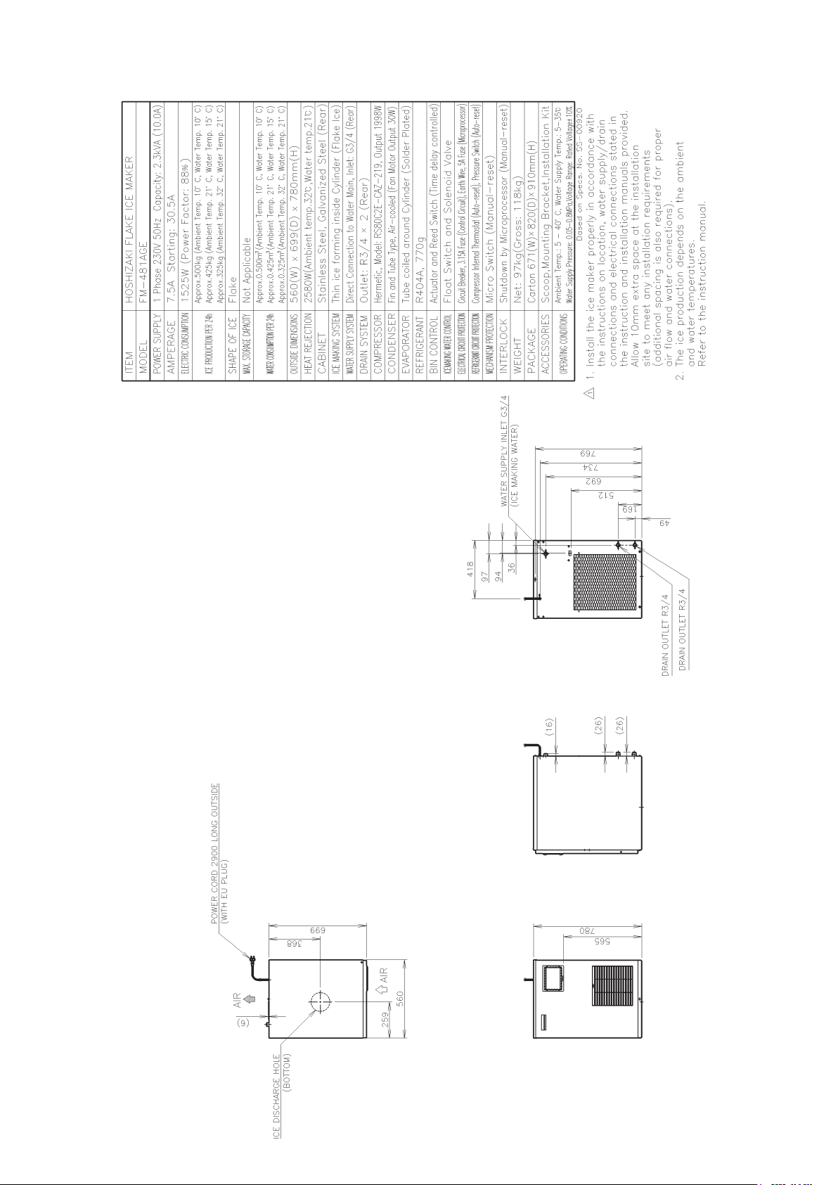
[e] FM-481AGE
7
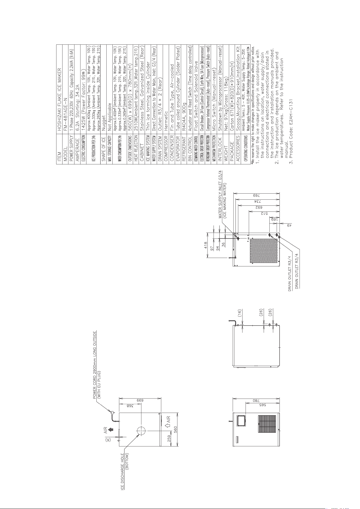
[f] FM-481AGE-N
8

[g] FM-481AWGE
9

[h] FM-481AWGE-N
10
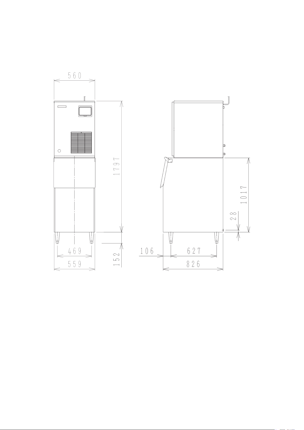
[i] WITH STORAGE BIN (B-300_F)
11

3. CONSTRUCTION
Modular aker models FM-251AFE/AWFE(-N) and FM-481AGE/AWGE(-N) include Water
Supply, Evaporator, Compressor, Condenser and Control Assemblies. As the unit is not
equipped with an Ice Storage Bin, this must be purchased separately as an optional extra.
[a] FM-251AFE/AWFE(-N)
Control Box
Evaporator
Gear Motor
Flush Water Valve
Control Water Valve
Ice Chute
Reservoir
Pressure Switch
Compressor Drier
12

[b] FM-481AGE/AWGE(-N)
Pressure Switch
Control Box
Evaporator
Gear Motor
Flush Water Valve
Ice Chute Control Water Valve
Reservoir
Compressor
Drier
13

II. MAINTENANCE AND CLEANING INSTRUCTIONS
IMPORTANT
1. This icemaker must be maintained individually, referring to the instruction
manual and labels provided with the icemaker.
2. To achieve optimum icemaker performance, the following parts need
periodic inspection and maintenance:
Extruding head (upper bearing)
Housing (lower bearing)
Mechanical seal
These parts should be inspected after two years from installation or 10,000
hours of operation, whichever comes rst, and once a year thereafter. Their
service life, however, depends on water quality and environment. More
frequent inspection and maintenance are recommended in bad or severe
water conditions.
1. EXTRUDING HEAD (UPPER BEARING), HOUSING (LOWER BEARING)
These parts should be replaced if a diametrical
gap of more than 0.5 mm is found when at least
0.5 mm Round Stock
or Pin Gauge
three spots are checked by changing the direction
of the auger on each bearing.
It depends on the water quality and conditions, but
normally the bearings should be checked for wear
Auger
Extruding
Head
after a total of 8,000 - 10,000 hour operation from
installation date.
Note: The clearance between the auger blades
and t he ev aporator i nter ior is 0.4 - 0.5
mm. If the bearings and rotating parts are
worn out to create a larger clearance, the
evaporator interior may be damaged. (The
For reference only
(May differ from actual design)
diameters differ by 0.8 - 1.0 mm.)
If the auger surfaces against which the bearings contact are no longer smooth or
show any burrs or abrasions during the above inspection, replace the auger.
2. MECHANICAL SEAL
The mechanical seal prevents water leaks from between the auger and the housing
bearing and gradually wears out to reduce its watertightness. Check the amount of water
leakage from the drain pipe located at the side of the gear case to determine the necessity
of replacement.
14

Total operation time Water leakage
3,000 hours 0.1 mL/h
10,000 hours 0.5 mL/h
Note: The water leakage will exceed the above amount with scale/dirt build up or damage
on the mating surface. Replace the mechanical seal when the water leakage
exceeds 0.5 mL/h.
3. GEAR MOTOR
After the following hours of operation, check the gear motor for excessive noise caused by
increased torque or deterioration of mechanical parts.
Bearing, gear and other mechanical parts: 10,000 hours
Oil seal: 5 years
Note: When the output shaft oil seal is exposed to a large amount of water at one time,
water may enter the gear case. Always drain the water circuit before removing the
auger for service.
4. CONDENSER
Check the condenser once a year, and clean if required by using a brush or vacuum
cleaner. More frequent cleaning may be required depending on the location of the
icemaker.
5. AIR FILTER (AIR-COOLED MODEL ONLY)
Plastic mesh Air Filters remove dirt or dust from the air and keep the Condenser from
getting clogged. If the Filters get clogged, the ice dispenser’s performance will be reduced.
Remove and clean the Air Filter at least twice per month:
1) Slide the Air Filter off the Louver.
2) Clean the Air Filter by using a vacuum cleaner.
When severely clogged, use warm water and a
neutral cleaner to wash the Air Filter.
3) Rinse and dry the Air Filter thoroughly, and place it
in position.
Air Filter
Louver
15

6. WATER VALVE
1) Disconnect the power source.
2) Close the water supply tap.
3) Disconnect the Inlet Hose from the Water Valve.
4) Remove the Mesh Filter from the Water Valve.
5) Clean the Mesh using a brush.
6) Replace the Mesh and Inlet Hose in their correct positions.
7) Open the water supply tap.
8) Connect the power source.
9) Check for leaks.
Coil
Do not remove
Filter
Packing
Inlet Hose
16

7. CLEANING OF WATER SYSTEM
WARNING
1. HOSHIZAKI recommends cleaning this unit at least twice a year. More
frequent cleaning, however, may be required in some existing water
conditions.
2. Do not touch the Operation Switch with damp hands.
3. Always wear rubber gloves, eye protectors, apron, etc. for safe handling of
the cleaner and sanitiser.
4. Use the cleaners and sanitisers recommended by Hoshizaki. Contact your
local Hoshizaki office for further details. (The instructions below give an
example of those recommended cleaners and sanitisers.)
5. Never mix cleaning and sanitising solutions in an attempt to shorten
cleaning time.
6. Wipe off any splashed or spilt cleaner/sanitiser immediately.
7. Do not use any ammonia type cleaners on any part of the icemaker.
<STEP 1>
Dilute the solutions with water as follows:
Cleaning solution: “Nickel-Safe Ice Machine Cleaner” by The Rectorseal Corporation
or similar. Prepare approximately 3 L of solution as directed on the
container.
Sanitising solution: 30 mL of 5 .2 5% sodium hypochlorite with 7.6 L of water or the
Hoshizaki recommended sanitiser as directed on the container.
IMPORTANT
For safety and maximum effectiveness, use the solutions immediately after
dilution.
<STEP 2>
Use the cleaning solution to remove lime deposits in the water system.
1) Open the Plastic Access Flap on the Front Panel.
17

2) Press the Stop Button to activate the ush cycle (approx. 10 minutes).
3) Remove all ice from the Storage Bin to avoid contamination by the cleaner.
4) Unplug the icemaker. Remove the Top and Front Panels.
5) Remove the Cover of the Reservoir. Remove any loose debris or scale.
6) Carefully ll the Reservoir with the solution to the overow point. If necessary, use a
small brush to clean the inside of the Reservoir.
7) Ret the Reservoir Cover.
8) Check that the Operation Switch is in the “RUN” position.
9) Loose t the Front and Top Panels.
10) Allow the icemaker to stand for about 10 minutes, then plug in the icemaker to make
ice with the solution.
11) With the water supply tap open, allow the machine to continue icemaking for a further
20 minutes. Open the Access Flap and press the Stop Button.
12) Allow time for the Gear Motor to stop and the water system to drain.
13) Unplug the icemaker.
14) Ret the Top and Front Panels. Plug in the icemaker.
15) Allow the icemaker to make ice for approximately 10 minutes.
16) Pour warm water into the Storage Bin to melt any ice down the drain.
Note: 1. If the machine has heavy deposits of scale, repeat the complete cleaning
procedure.
2. Do not increase the proportion of cleaning solution to shorten cleaning times, as
this may lock the Auger when completing item 10).
<STEP 3>
Note: Sanitising should always be completed after cleaning or alternately as an individual
procedure if conditions exist to make it necessary.
Use 2.8 lit. of the sanitising solution to sanitise the icemaker.
17) Follow items 1) to 16) to complete sanitisation of the water system.
18

8. PERIODICAL CLEANING
1) Machine and Bin Exterior
Wipe the exterior at least once per week with a clean, soft cloth. Use a damp cloth
containing a neutral cleaner to wipe off grease or dirt.
2) Storage Bin Interior Cleaning/Sanitisation (as required)
1) Open the Storage Bin Door, and remove all ice.
2) Wash the Bin Liner, Ice Deector and Door inner surface with a neutral non-abrasive
cleaner. Rinse thoroughly with a clean cloth and fresh water.
3) Mix 5 litres of water with 18 mL of 5.25% sodium hypochlorite solution in a suitable
container or the recommended Hoshizaki sanitiser as directed.
4) Soak a clean sponge or cloth with the solution and wipe all the surfaces of the Bin Liner,
Ice Deector and Door inner surface.
5) Rinse thoroughly with fresh water and a clean cloth to wipe off the solution. Close the
Bin Door.
Note: Some solutions may cause damage to the Bin liner surfaces or corrosion on the
metal parts. Always rinse the sanitiser unless directed otherwise by Hoshizaki
guidelines.
19

III. TECHNICAL INFORMATION
1. WATER CIRCUIT AND REFRIGERANT CIRCUIT
[a] FM-251AFE(-N)
Pressure Switch
Cut-out 28.5 ± 1.5/0 bar
Cut-in 23.0 ± 1.5 bar
20

[b] FM-251AWFE(-N)
Pressure Switch
Cut-out 28.0 ± 1.5/0 bar
Cut-in 23.0 ± 1.5 bar
21

[c] FM-481AGE(-N)
Pressure Switch
Cut-out 28.5 ± 1.5/0 bar
Cut-in 23.0 ± 1.5 bar
22

[d] FM-481AWGE(-N)
Pressure Switch
Cut-out 22.0 ± 1.5/0 bar
Cut-in 18.0 ± 1.5 bar
23

2. WIRING DIAGRAM
[a] WIRING DIAGRAM
FM-251AFE(-N), FM-251AWFE(-N)
24

FM-481AGE(-N)
25

FM-481AWGE(-N)
26
 Loading...