

Hoshizaki FM-150KE, FM-150KE-N, CM-140KE, FM-150KE-50, FM-150KE-50-N SERVICE MANUAL
...
NO. F080-869
ISSUED: APR. 25, 2012
REVISED: APR. 25, 2014
HOSHIZAKI
SELF-CONTAINED ICE MAKER
MODEL
FM-150KE(-N)
CM-140KE
FM-150KE-50(-N)
FM-120KE
CM-110KE-50
FM-80KE(-N)
SERVICE MANUAL

CONTENTS
I. SPECIFICATIONS-------------------------------------------------------------------------------------- 1
1. DIMENSIONS/SPECIFICATIONS ----------------------------------------------------------------- 1
[a] FM-150KE ------------------------------------------------------------------------------------------- 1
[b] FM-150KE-N ---------------------------------------------------------------------------------------- 2
[c] CM-140KE ------------------------------------------------------------------------------------------- 3
[d] FM-150KE-50 --------------------------------------------------------------------------------------- 4
[e] FM-150KE-50-N------------------------------------------------------------------------------------ 5
[f] FM-120KE -------------------------------------------------------------------------------------------- 6
[g] CM-110KE-50--------------------------------------------------------------------------------------- 7
[h] FM-80KE--------------------------------------------------------------------------------------------- 8
[i] FM-80KE-N------------------------------------------------------------------------------------------- 9
2. CONSTRUCTION-------------------------------------------------------------------------------------10
[a] FM-150KE(-N), CM-140KE, FM-150KE-50(-N), FM-120KE, CM-110KE-50 -------10
[b] FM-80KE(-N)---------------------------------------------------------------------------------------11
II. MAINTENANCE AND CLEANING INSTRUCTIONS-----------------------------------------12
1. EXTRUDING HEAD (UPPER BEARING), HOUSING (LOWER BEARING) -----------12
2. MECHANICAL SEAL---------------------------------------------------------------------------------12
3. GEAR MOTOR-----------------------------------------------------------------------------------------13
4. CONDENSER (AIR-COOLED MODEL ONLY) ------------------------------------------------13
5. AIR FILTER (AIR-COOLED MODEL ONLY) ---------------------------------------------------13
6. CONTROL WATER VALVE ------------------------------------------------------------------------14
7. CLEANING OF WATER SYSTEM----------------------------------------------------------------15
III. TECHNICAL INFORMATION----------------------------------------------------------------------18
1. WATER CIRCUIT AND REFRIGERANT CIRCUIT-------------------------------------------18
[a] FM-150KE(-N), CM-140KE, FM-150KE-50(-N), FM-120KE, CM-110KE-50 -------18
[b] FM-80KE(-N)---------------------------------------------------------------------------------------19
2. WIRING DIAGRAM -----------------------------------------------------------------------------------20
[a] WIRING DIAGRAM-------------------------------------------------------------------------------20
[b] CONTROL BOX LAYOUT ----------------------------------------------------------------------22
3. ICEMAKING MECHANISM -------------------------------------------------------------------------23
[a] EVAPORATOR (CASING)----------------------------------------------------------------------24
[b] AUGER----------------------------------------------------------------------------------------------24
[c] EXTRUDING HEAD (BEARING)--------------------------------------------------------------24
[d] HOUSING-------------------------------------------------------------------------------------------24
[e] MECHANICAL SEAL-----------------------------------------------------------------------------24
[f] COUPLING (SPLINE JOINT)-------------------------------------------------------------------24
[g] GEAR MOTOR ------------------------------------------------------------------------------------24
[h] BELT HEATER ------------------------------------------------------------------------------------25
[i] REMOVABLE FLANGE -------------------------------------------------------------------------- 25
[j] SEALING BOLT------------------------------------------------------------------------------------25
4. ELECTRIC CIRCUIT ---------------------------------------------------------------------------------26
[a] BASIC OPERATION -----------------------------------------------------------------------------26
[b] TIMING CHART -----------------------------------------------------------------------------------27
5. OPERATION BOARD--------------------------------------------------------------------------------28
[a] OPERATION BUTTONS------------------------------------------------------------------------28
i
PAGE

[b] SETTING MODEL NUMBER-------------------------------------------------------------------28
[c] DISPLAYING COMPRESSOR OPERATING HOURS, CYCLE TIME, MODEL
NUMBER AND SOFTWARE VERSION -----------------------------------------------------29
[d] DISPLAYING ERROR LOG--------------------------------------------------------------------31
[e] RESETTING ERROR LOG---------------------------------------------------------------------32
[f] RESETTING COMPRESSOR OPERATING HOURS------------------------------------32
[g] REDUCING COMPRESSOR STARTING TIME-------------------------------------------32
6. PROTECTORS ----------------------------------------------------------------------------------------33
[a] INDICATION ---------------------------------------------------------------------------------------33
7. ERROR CODES---------------------------------------------------------------------------------------34
8. PERFORMANCE DATA-----------------------------------------------------------------------------36
[a] FM-150KE, FM-150KE-50 ----------------------------------------------------------------------36
[b] FM-150KE-N, FM-150KE-50-N----------------------------------------------------------------37
[c] CM-140KE ------------------------------------------------------------------------------------------38
[d] FM-120KE ------------------------------------------------------------------------------------------39
[e] CM-110KE-50--------------------------------------------------------------------------------------40
[f] FM-80KE---------------------------------------------------------------------------------------------41
[g] FM-80KE-N-----------------------------------------------------------------------------------------42
IV. SERVICE DIAGNOSIS -----------------------------------------------------------------------------43
1. NO ICE PRODUCTION------------------------------------------------------------------------------43
2. LOW ICE PRODUCTION----------------------------------------------------------------------------45
3. OTHERS-------------------------------------------------------------------------------------------------45
V. REMOVAL AND REPLACEMENT OF COMPONENTS-------------------------------------47
1. SERVICE FOR REFRIGERANT LINES ---------------------------------------------------------47
[a] SERVICE INFORMATION----------------------------------------------------------------------47
[b] REFRIGERANT RECOVERY------------------------------------------------------------------48
[c] EVACUATION AND RECHARGE-------------------------------------------------------------48
2. BRAZING------------------------------------------------------------------------------------------------ 50
3. COMPRESSOR----------------------------------------------------------------------------------------50
4. DRIER----------------------------------------------------------------------------------------------------51
5. EXPANSION VALVE ---------------------------------------------------------------------------------52
6. WATER REGULATING VALVE - WATER-COOLED MODEL ONLY --------------------53
7. EVAPORATOR ASSEMBLY -----------------------------------------------------------------------54
8. CONTROL WATER VALVE ------------------------------------------------------------------------57
9. FLUSH WATER VALVE -----------------------------------------------------------------------------57
10. CONTROLLER BOARD -----------------------------------------------------------------------------58
[a] MODIFICATION-----------------------------------------------------------------------------------58
[b] REPLACEMENT ----------------------------------------------------------------------------------58
ii
I. SPECIFICATIONS
1. DIMENSIONS/SPECIFICATIONS
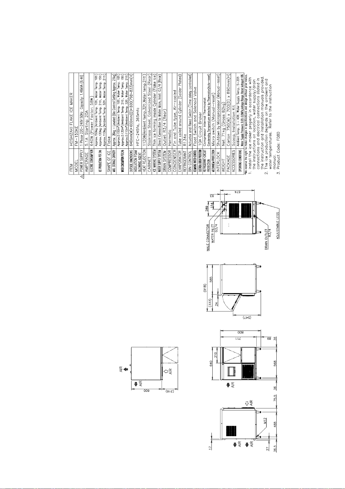
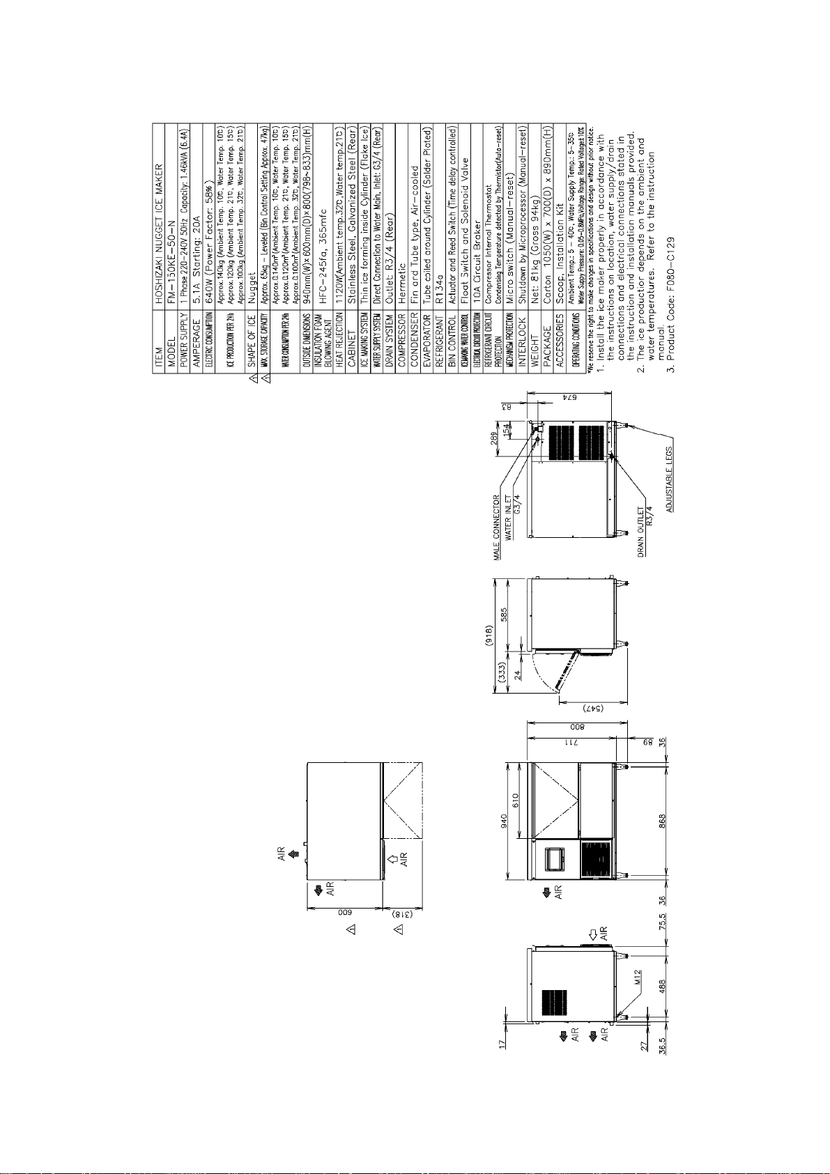
[a] FM-150KE
1
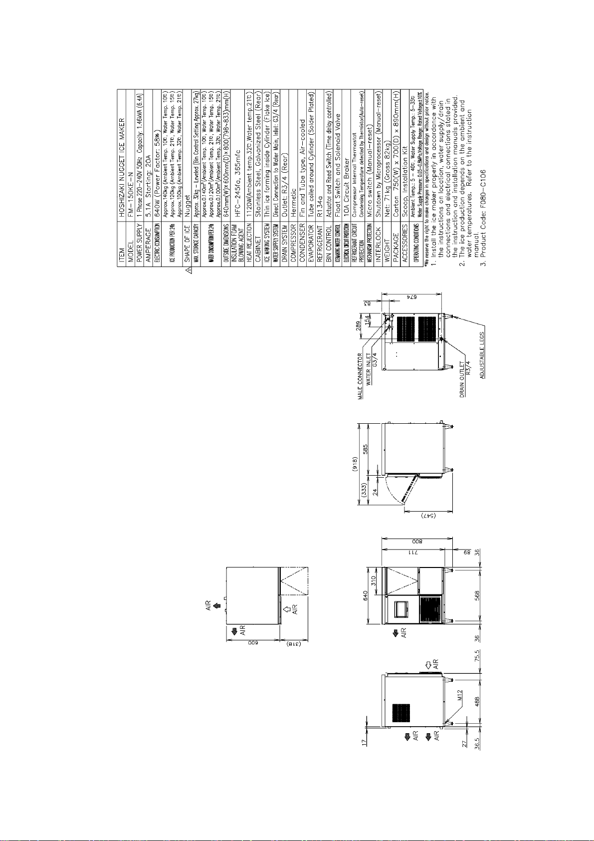
[b] FM-150KE-N
2
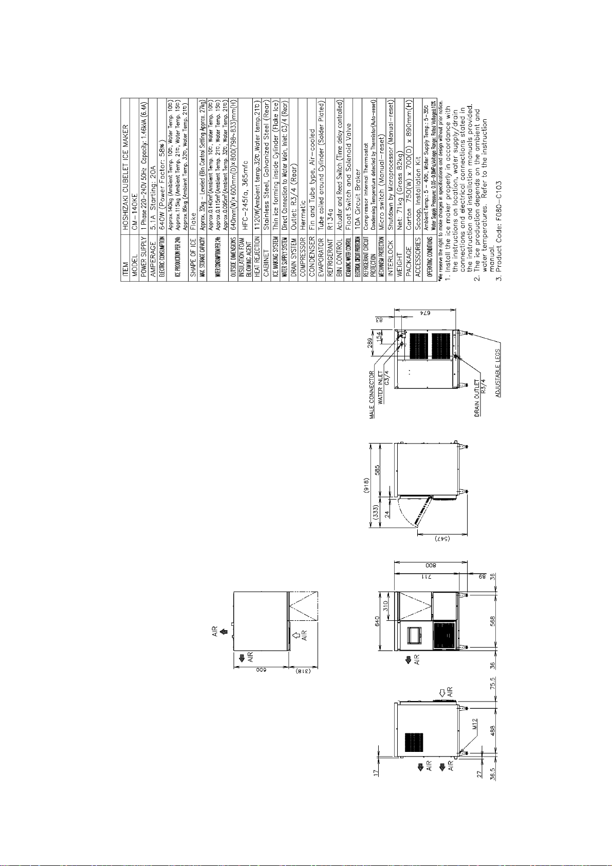
[c] CM-140KE
3
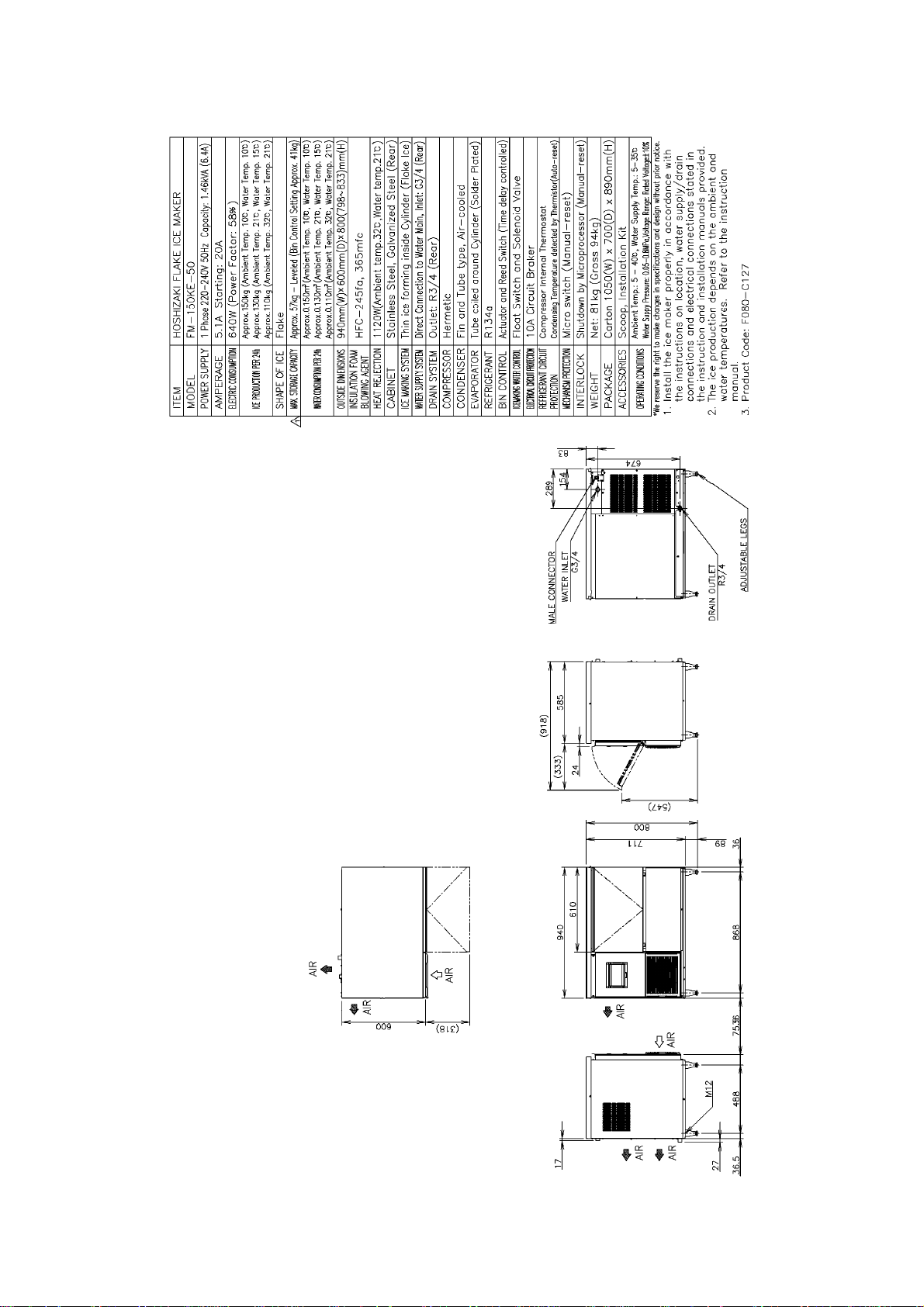
[d] FM-150KE-50
4
[e] FM-150KE-50-N
5
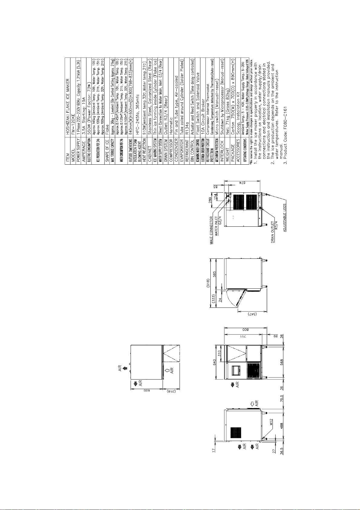
[f] FM-120KE
6
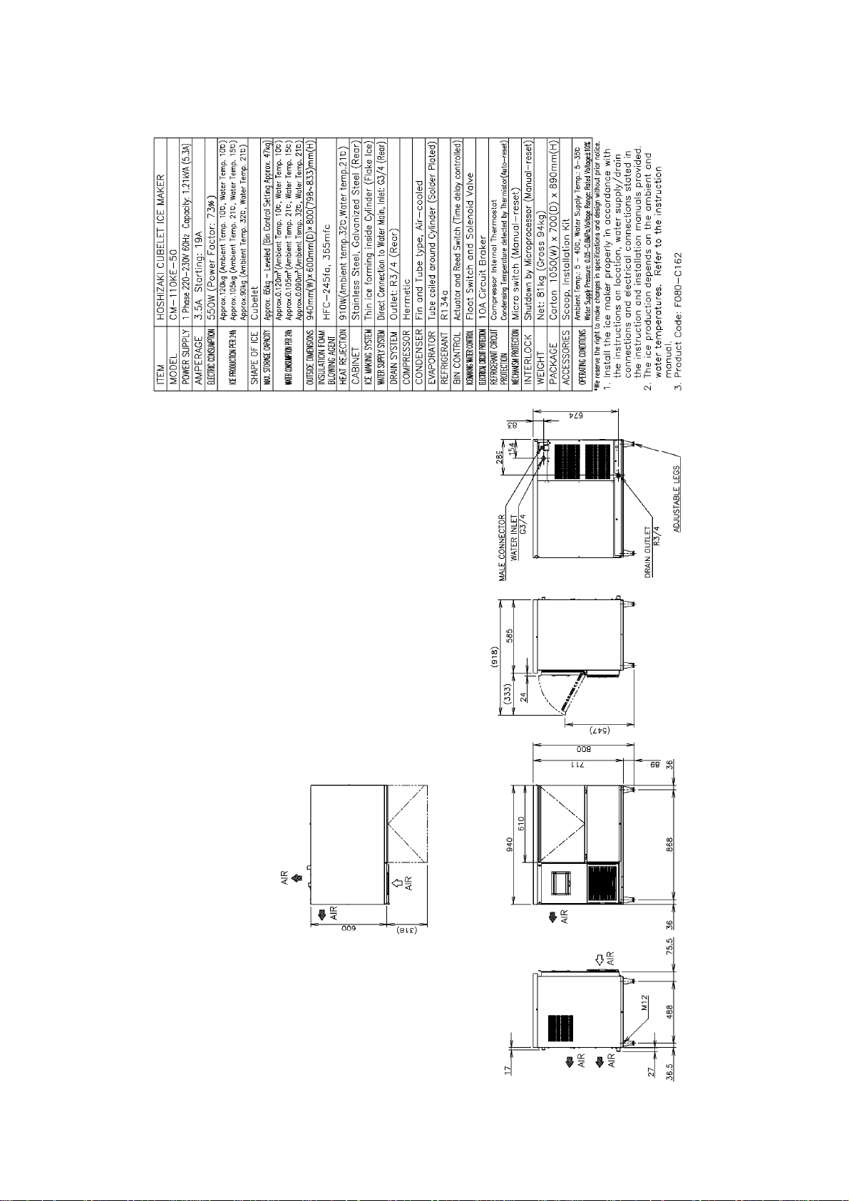
[g] CM-110KE-50
7
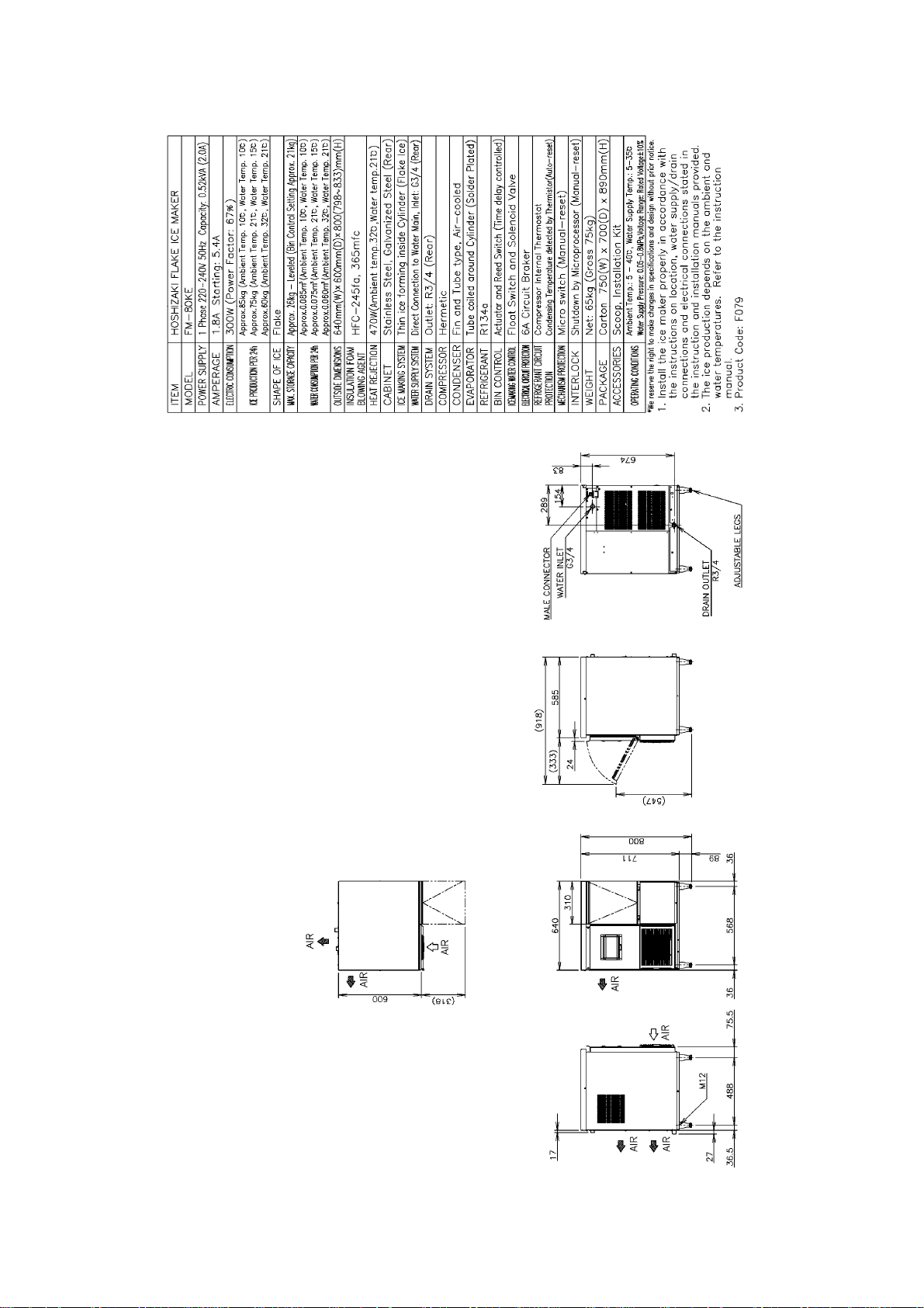
[h] FM-80KE
8
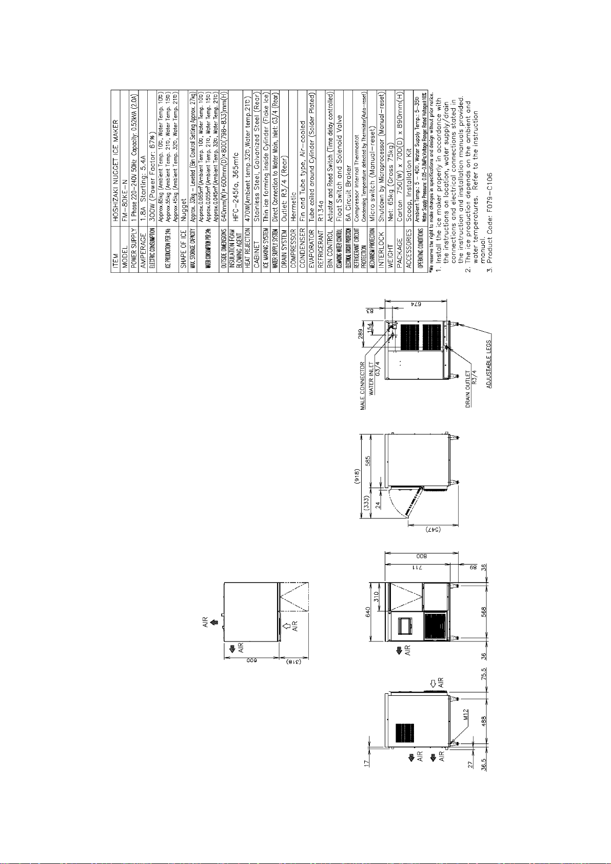
[i] FM-80KE-N
9
2. CONSTRUCTION
[a] FM-150KE(-N), CM-140KE, FM-150KE-50(-N), FM-120KE, CM-110KE-50
Bin Control Switch
Control W a te r Valve
Evaporator
Reservoir
Control Box
Compressor
Gear Motor
Air-Cooled CondenserFan MotorFlush Water Valve
10
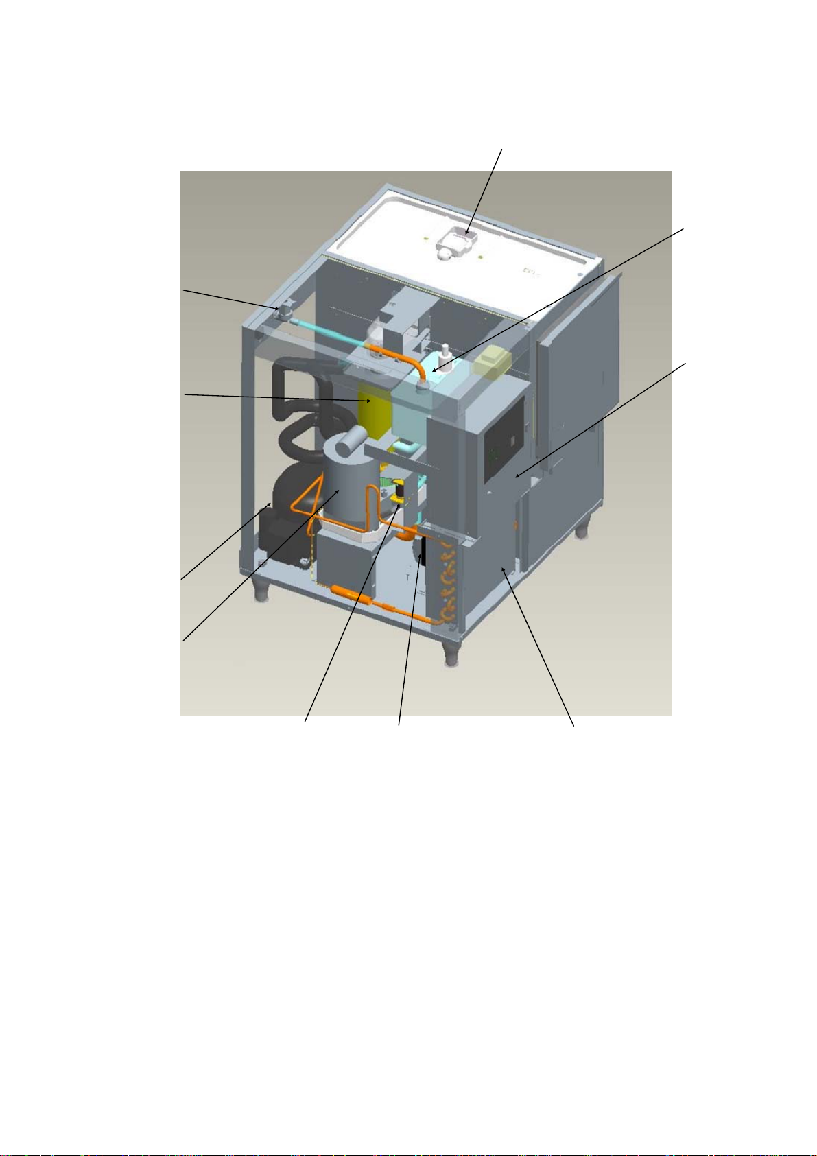
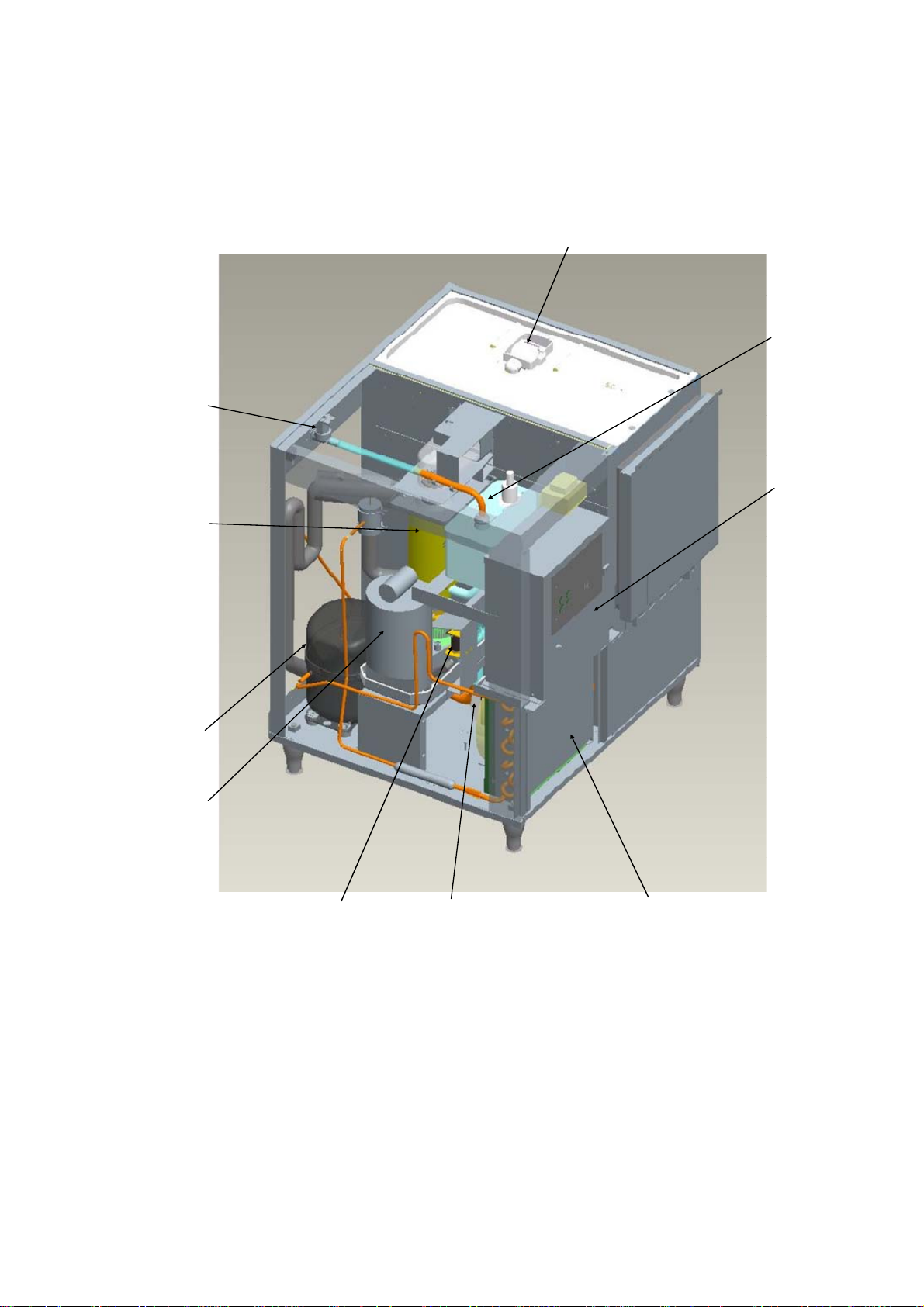
[b] FM-80KE(-N)
Control Water Valve
Evaporator
Bin Control Switch
Reservoir
Control Box
Compressor
Gea r Motor
Flush Wat er Valve
Air-Co oled CondenserFan Motor
11
II. MAINTENANCE AND CLEANING INSTRUCTIONS
IMPORTANT
1. This icemaker must be maintained individually, referring to the instruction manual
and labels provided with the icemaker.
2. To achieve optimum icemaker performance, the following parts need periodic
inspection and maintenance:
Extruding head (upper bearing)
Housing (lower bearing)
Mechanical seal
These parts should be inspected after two years from installation or 10,000 hours of
operation, whichever comes first, and once a year thereafter. Their service life,
however, depends on water quality and environment. More frequent inspection and
maintenance are recommended in bad or severe water conditions.
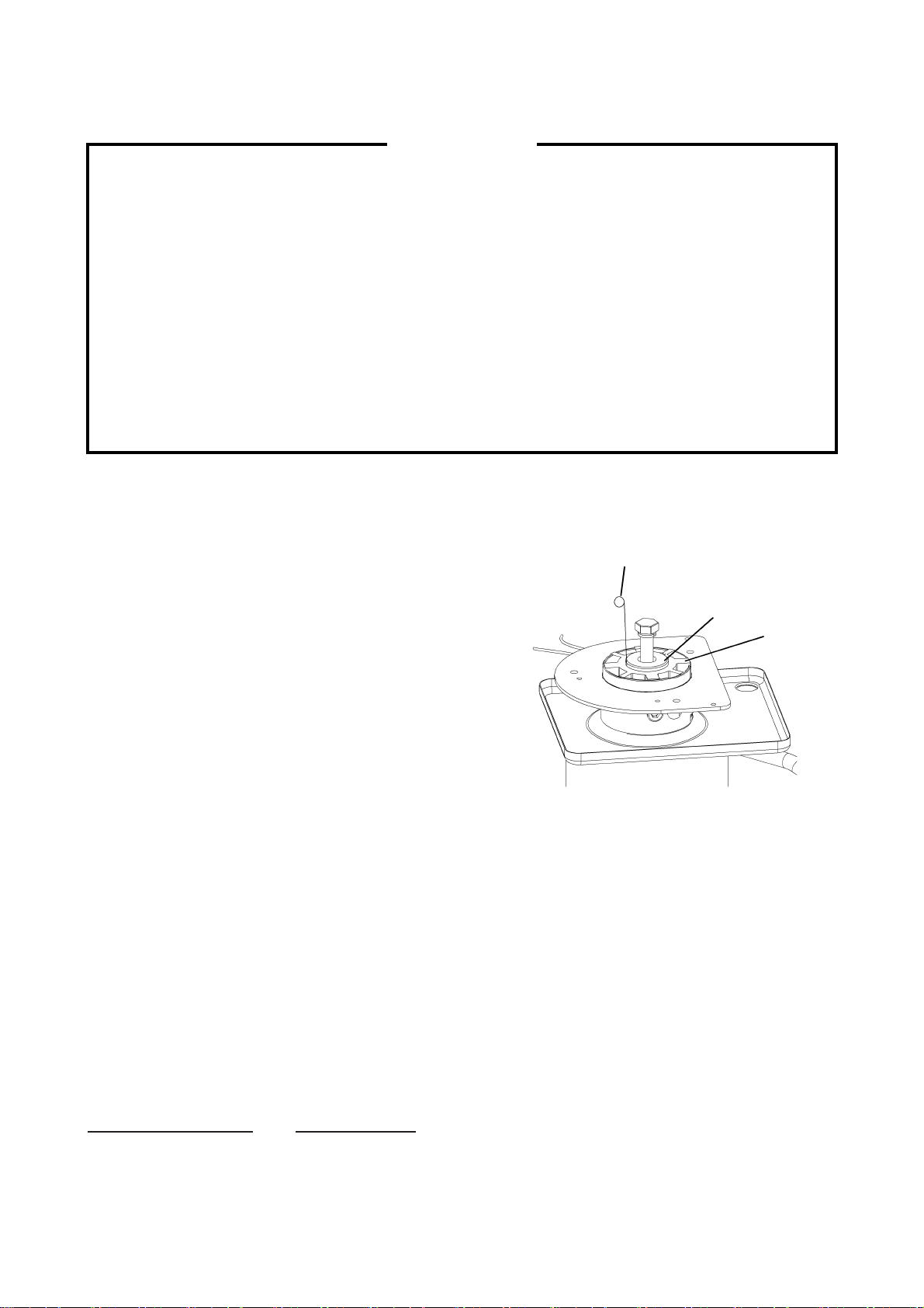
1. EXTRUDING HEAD (UPPER BEARING), HOUSING (LOWER BEARING)
These parts should be replaced if a diametrical gap
of more than 0.5 mm is found when at least three
spots are checked by changing the direction of the
auger on each bearing.
It depends on the water quality and conditions, but
normally the bearings should be checked for wear
after a total of 8,000 - 10,000 hour operation from
installation date.
Note: The clearance between the auger blades
and the evaporator interior is 0.4 - 0.5 mm. If
the bearings and rotating parts are worn out
to create a larger clearance, the evaporator
interior may be damaged. (The diameters
(May differ from actual design)
differ by 0.8 - 1.0 mm.)
If the auger surfaces against which the bearings contact are no longer smooth or
show any burrs or abrasions during the above inspection, replace the auger. The
sealing bolt must be tightened equally to torque of 784N·cm±10%.
0.5 mm Round Stock
or Pin Gauge
For reference only
Auger
Extruding
Head
2. MECHANICAL SEAL
The mechanical seal prevents water leaks from between the auger and the housing bearing
and gradually wears out to reduce its watertightness. Check the amount of water leakage
from the drain pipe located at the side of the gear case to determine the necessity of
replacement.
Total operation time Water leakage
3,000 hours 0.1 mL/h
10,000 hours 0.5 mL/h
12
Attach the mechanical seal with its floating sheet facing the housing. After replacement,
there should be no water leakage from the mating surface.
Note: The water leakage will exceed the above amount with scale/dirt build up or damage
on the mating surface. Replace the mechanical seal when the water leakage exceeds
0.5 mL/h.
3. GEAR MOTOR
After the following hours of operation, check the gear motor for excessive noise caused by
increased torque or deterioration of mechanical parts.
Bearing, gear and other mechanical parts: 10,000 hours
Oil seal: 5 years
Note: When the output shaft oil seal is exposed to a large amount of water at one time,
water may enter the gear case. Always drain the water circuit before removing the
auger for service.
4. CONDENSER (AIR-COOLED MODEL ONLY)
Check the condenser once a year, and clean if required by using a brush or vacuum cleaner.
More frequent cleaning may be required depending on the location of the icemaker.
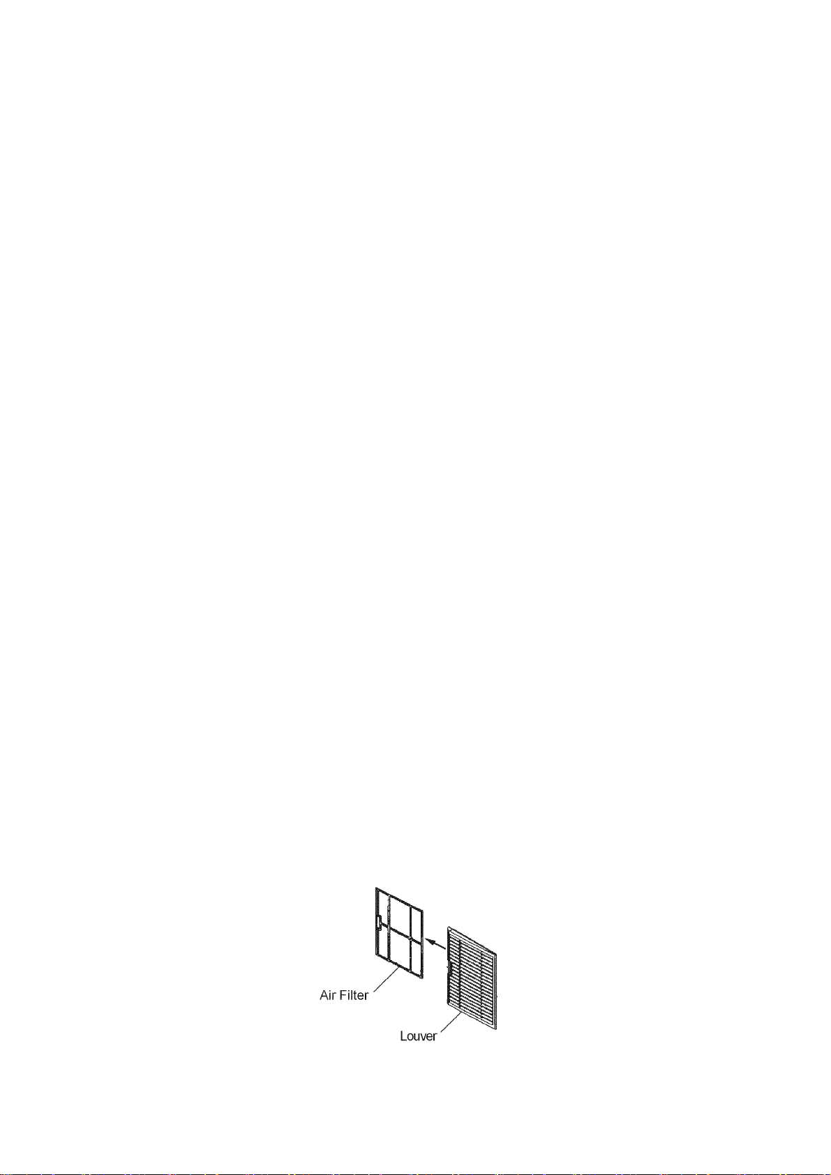
5. AIR FILTER (AIR-COOLED MODEL ONLY)
Plastic mesh air filters remove dirt or dust from the air, and keep the condenser from getting
clogged. If the filters get clogged, the icemaker’s performance will be reduced. Remove and
clean the air filters at least twice per month:
1) Slide the air filter off the louver.
2) Clean the air filter by using a vacuum cleaner. When severely clogged, use warm water
and a neutral cleaner to wash the air filter.
3) Rinse and dry the air filter thoroughly, and place it in position.
13
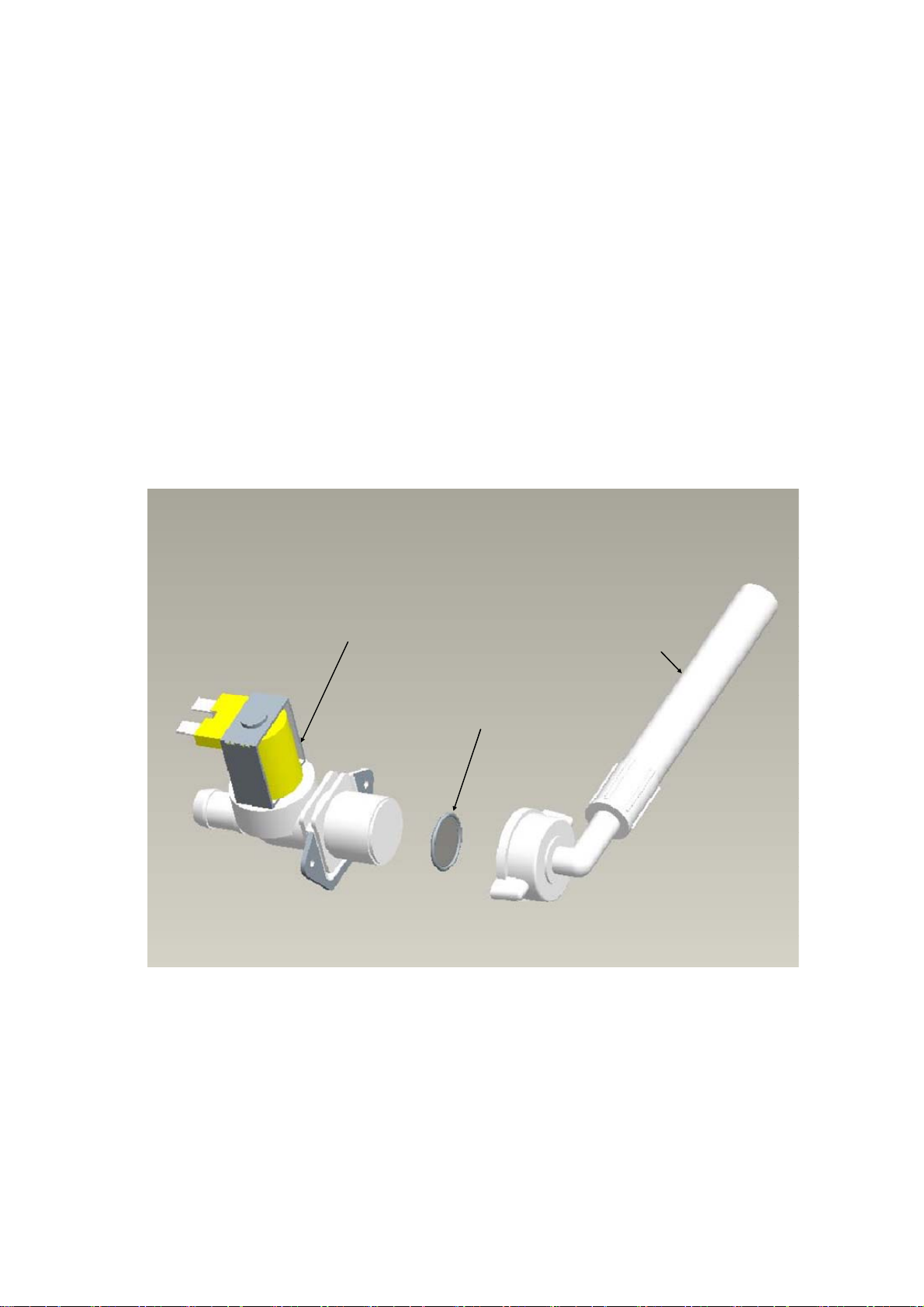
6. CONTROL WATER VALVE
1) Disconnect the power source.
2) Close the water supply tap.
3) Disconnect the inlet hose from the water valve.
4) Clean the filter packing using a brush.
5) Replace the filter packing and inlet hose in their correct positions.
6) Open the water supply tap.
7) Connect the power source.
8) Check for leaks.
Control Wat er Valve
Filter Packing
Inlet Hose
14
7. CLEANING OF WATER SYSTEM
WARNING
1. HOSHIZAKI recommends cleaning this unit at least twice a year. More frequent
cleaning, however, may be required in some existing water conditions.
2. Do not touch the operation switch with damp hands.
3. Always wear rubber gloves, eye protectors, apron, etc. for safe handling of the
cleaner and sanitiser.
4. Use the cleaners and sanitisers recommended by Hoshizaki. Contact your local
Hoshizaki office for further details. (The instructions below give an example of
those recommended cleaners and sanitisers.)
5. Never mix cleaning and sanitising solutions in an attempt to shorten cleaning time.
6. Wipe off any splashed or spilt cleaner/sanitiser immediately.
7. Do not use any ammonia type cleaners on any part of the icemaker.
CAUTION
Do not use ice produced with cleaning and sanitizing solutions. Be sure none remains
in the storage bin on completion of cleaning.
<STEP 1>
Dilute the solutions with water as follows:
Cleaning solution: “Nickel-Safe Ice Machine Cleaner” by The Rectorseal Corporation or
similar. Prepare approximately 3 L of solution as directed on the
container.
Sanitising solution: 30 mL of 5.25% sodium hypochlorite with 7.6 L of water or the
Hoshizaki recommended sanitiser as directed on the container.
IMPORTANT
For safety and maximum effectiveness, use the solutions immediately after dilution.
<STEP 2>
Use the cleaning solution to remove lime deposits in the water system.
1) Open the plastic access flap on the front panel.
2) Press the stop button to activate the flush cycle (approx. 10 minutes).
15

3) Remove all ice from the storage bin to avoid contamination by the cleaner.
4) Unplug the icemaker. Remove the top and front panels.
5) Remove the cover of the reservoir. Remove any loose debris or scale.
6) Carefully fill the reservoir with the solution to the overflow point. If necessary, use a small
brush to clean the inside of the reservoir.
7) Refit the reservoir cover.
8) Check that the operation switch is in the “ON” position.
9) Refit the front and top panels.
10) Allow the icemaker to stand for about 10 minutes, then plug in the icemaker to make ice
with the solution.
11) With the water supply tap open, allow the machine to continue icemaking for a further 20
minutes. Open the access flap and press the stop button.
12) Allow time for the gear motor to stop and the water system to drain.
13) Allow the icemaker to make ice for approxim ately 10 minutes.
14) Pour warm water into the storage bin to melt any ice down the drain.
Note: 1. If the machine has heavy deposits of scale, repeat the complete cleaning
procedure.
2. Do not increase the proportion of cleaning solution to shorten cleaning times, as
this may lock the auger when completing item 10).
<STEP 3>
Note: Sanitising should always be completed after cleaning or alternately as an individual
procedure if conditions exist to make it necessary.
Use 2.8 litres of the sanitising solution to sanitise the icemaker.
15) Follow items 1) to 14) to complete sanitisation of the water system.
<STEP 4>
Use the remaining sanitising solution to sanitise removable parts.
16) Open the door and remove the actuator assembly from the upper panel by pushing the
tabs on the actuator base inward.
17) Remove the reed switch and the actuator from the actuator base.
18) Remove the thumbscrews, the spout and the spout gasket.
16
 Loading...