

Page 1

Hoshizaki
Hoshizaki America, Inc.
Cubelet Icemaker / Dispenser
Models
DCM-751BAH
“A Superior Degree
of Reliability”
www.hoshizaki.com
DCM-751BAH-OS
DCM-751BWH
DCM-751BWH-OS
PARTS LIST
Number: 71321
Issued: 7-18-2011
Revised: 3-5-2015
Page 2

CONTENTS
Auxiliary Codes ...................................................................................................................... 3
Note About Ordering Parts .................................................................................................... 3
A. Ice Dispenser Assembly .................................................................................................... 4
B. Refrigeration Circuit ........................................................................................................... 7
DCM-751BAH(-OS) ........................................................................................................... 7
DCM-751BWH(-OS) .......................................................................................................... 9
C. Ice Making Unit ................................................................................................................11
D. Water Circuit .................................................................................................................... 13
E. Control Box Assembly...................................................................................................... 15
F. Shutter Assembly ............................................................................................................. 17
G. Dispensing & Agitating Gear Motor Assemblies .............................................................. 20
H. Bin Assembly ................................................................................................................... 22
J. Accessories & Labels ....................................................................................................... 24
2
Page 3

Auxiliary Codes
DCM-751BAH A-0 March 2011
B-0 January 2012
C-0 January 2013
D-0 January 2014
D-1 May 2014
E-0 January 2015
DCM-751BAH-OS A-0 August 2011
B-0 January 2012
C-0 January 2013
D-0 January 2014
D-1 May 2014
E-0 January 2015
DCM-751BWH A-0 March 2011
B-0 March 2012
C-1 March 2013
D-0 February 2014
D-1 May 2014
E-0 January 2015
DCM-751BWH-OS A-0 June 2011
B-0 March 2012
C-1 March 2013
D-0 February 2014
D-1 September 2014
E-0 January 2015
Auxiliary Code Breakdown
The auxiliary code is the rst two characters in the serial number. The rst character
indicates the year. Years progress or regress in alphabetical order. The series runs from
"A" through "V" and the letters "I" and "O" are skipped. The second character indicates
signicant part changes within a year. Base is "0" and this number advances for each
change. In cases where there is a letter in parentheses, this designates the month. This is
the last character in the serial number. The series runs from "(A)" through "(M)" and the
letter "(I)" is skipped. This designation is only included when identifying a parts change
within an auxiliary code.
Note About Ordering Parts
Most assemblies cannot be ordered as complete units; parts in the assemblies generally
must be ordered separately.
3
Page 4
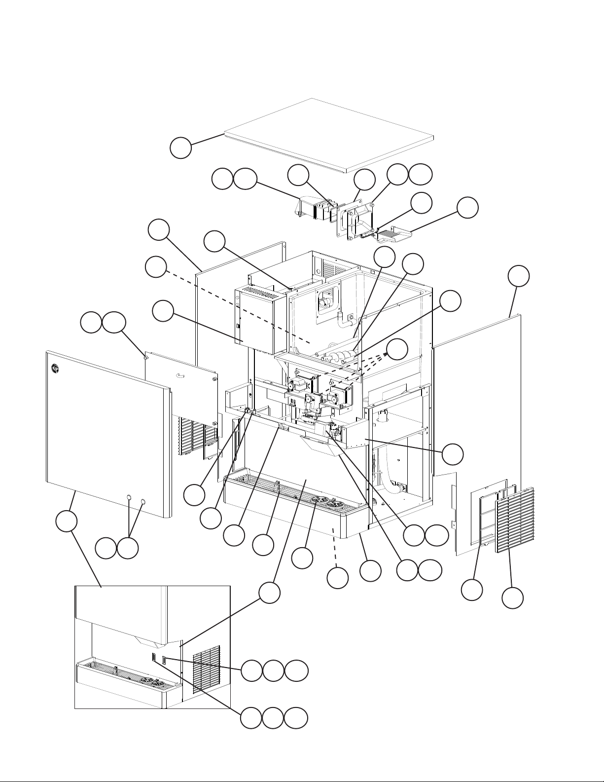
A. Ice Dispenser Assembly
DCM-751B_H(-OS)
A-0 to E-0
1
15
15a
16
17
14
14a
19
3
21
24
26
8
9a
9
23
22
18
2
25
27
31
33
32
DCM-751B_H-OS
28
29
30
12
6
3635
34 36
11
36a
36a
10a
10
20a
13
4
7
20
5
4
Page 5

Title: A. Ice Dispenser Assembly Model: DCM-751B_H(-OS)
Index
No. Description
1 Top Panel 3A2526G01 1
2 Right Side Panel DCM-751BAH(-OS) 2A6442-01 1
3 Left Side Panel DCM-751BAH(-OS) 2A6443-01 1
4 Louver DCM-751BAH(-OS) 103121-03 2
5 Air Filter DCM-751BAH(-OS) 208283G03 2
6 Apron Panel DCM-751B_H 2A6495-01 1
7 Panel (Lower) 228436G01 1
8 Control Box Panel 4A5054-01 1
9 Storage Bin Cover 228433A01 1
9a Thumbscrew 415949G12 4
10 Ice Chute 4A2204-01 1
10a Thumbscrew 415949G08 2
11 Cup Guide 326702-01 2
12 Grille 216100G01 1
13 Drip Tray 2A2591G02 1
14 Spout B 208807-01 1
14a Thumbscrew 415949G11 4
15 Spout 103329G01 1
15a Thumbscrew 415949G11 3
16 Spout Packing A 427195-01 1
17 Spout Packing B 427196-01 1
18 Guide 2111 71-01 1
19 Packing 320668-01 1
20 Spout Cover 215773-01 1
20a Thumbscrew 415949G08 2
21 Ground Screw 433304-02 1
22 Gasket 429758-01 3
23 Auger 3A6535G01 1
24 Left Agitator 319017G02 1
25 Right Agitator 321013G01 1
26 Drain Pan 323765G01 1
27 Middle Front Frame 2A4756G01 1
28 Control Switch (rocker) 4A1034-01 1
29 Dispense Switch (rocker) 4A0558-01 1
30 Safety Switch (plunger) 4A5034-01 1
Material or
Model Number Part Number
DCM-751BWH(-OS) 2A6442-02 1
DCM-751BWH(-OS) 2A6443-02 1
DCM-751B_H-OS 3A6512G01 1
Required Number
A-0
to
E-0
5
Page 6

Title: A. Ice Dispenser Assembly Model: DCM-751B_H(-OS)
Index
No. Description
31 Front Panel DCM-751B_H 3A6515G01 1
32 Push Switch Assembly
(includes item 33)
33 Push Switch DCM-751B_H 435745-02 2
34 Ice Sensor Assembly DCM-751B_H-OS 4A3753G01 1
35 Water Sensor Assembly DCM-751B_H-OS 4A3753G02 1
36 Sensor Latch DCM-751B_H-OS 4A3848-01 2
36a Thumbscrew DCM-751B_H-OS 415949G10 2
Material or
Model Number Part Number
DCM-751B_H-OS 2A6496-02 1
DCM-751B_H 3A4997A01 1
Required Number
A-0
to
E-0
6
Page 7

B. Refrigeration Circuit
DCM-751BAH(-OS)
A-0 to E-0
11
8
7
11
6
5a
5
3
9
4
2
12
1
7
Page 8

Title: B. Refrigeration Circuit Model: DCM-751BAH(-OS)
Index
No. Description
1 Compressor
2 Condenser 3A0821-01 1
3 Fan Motor Bracket 3A0650-01 1
4 Shroud 340990-01 1
5 Fan Motor 4A3158-01 1
5a Self-Locking Nut 8-32 7N21I0832 4
6 Fan Blade 444898-01 1
7 Thermostatic Expansion
Val ve
8 Thermostatic Expansion
Valve Cover
9 Drier 4A1113-01 1
10 Thermostatic Expansion
Valve Bulb Holder
11 Heat Exchanger 2A6126A01 1
12 High-Pressure Switch 463180-04 1
Material or Model
Number Part Number
RST61C1E-CFA-202
4A5158-01 1
4A1117-01 1
4A1168-01 1
3A0112-01 1
Required Number
A-0
to
E-0
8
Page 9

B. Refrigeration Circuit
DCM-751BWH(-OS)
A-0 to E-0
3
4
6
9
7
8
2
10
5
1
9
Page 10

Title: B. Refrigeration Circuit Model: DCM-751BWH(-OS)
A-0
Index
No. Description
1 Compressor
2 Condenser HS-5099 2A2359G03 1 -
3 Thermostatic Expansion
Valve
4 Thermostatic Expansion
Valve Cover
5 Drier 4A1113-01 1 1
6 Thermostatic Expansion
Valve Bulb Holder
7 Water Regulator 4A0911-04 1 1
8 Male Connector 4A1087-01 1 1
9 Heat Exchanger 2A6126A01 1 1
10 High-Pressure Switch 463180-05 1 1
Material or Model
Number Part Number
RST61C1E-CFA-202
4A5158-01 1 1
3A7323-01 1
4A1117-01 1 1
4A1168-01 1 1
3A0112-01 1 1
to
B-0
Required Number
C-1
to
E-0
10
Page 11

C. Ice Making Unit
DCM-751B_H(-OS)
A-0 to E-0
7a 7b
7
8
10
13
12
12a
3
11
9
11a
9a 9b
6
5
2a 2b
2
1a 1b
1
4
11
Page 12

Title: C. Ice Making Unit Model: DCM-751B_H(-OS)
Index
No. Description
1 Gear Motor 4A2007-01 1
1a Socket Head Cap Screw 8x110, SS 7S12-0811 3
1b Split Lock Washer M8, SS 7L22-0800 3
2 Gear Motor Barrier 3A1732-01 1
2a Truss Head Screw 4×8 7C31-0408 2
2b Rubber Washer 4A5268-01 2
3 Heater (includes spring) 4A2292-01 1
4 Spline Coupling 4A3204-01 1
5 O-ring 4A4755-02 1
6 Mechanical Seal 432492-01 1
7 Extruding Head 216530G04 1
7a Washer 427184-01 4
7b Seal Bolt M8 P01768-01 4
8 Cutter 427183G01 1
9 Evaporator 2A3314G01 1
9a Split Lock Washer M8, SS 7L22-0800 4
9b Socket Head Cap Screw 8×12, SS 7S12-0812 4
10 Auger 120863G02 1
11 Housing 2A1977G01 1
11a Hex Bolt 8×30, SS 7B02-0830 6
12 Evaporator Bracket 3A0360-01 1
12a Hex Head Bolt w/Washer 5×10, SS 7B0230510 2
13 Packing 427151-02 1
Material or
Model Number Part Number
Required Number
A-0
to
E-0
12
Page 13

D. Water Circuit
DCM-751B_H(-OS)
A-0 to E-0
5
9
26
3
4
2
14
18
22
7
20
6
25a
25
24
19
10 26
1
21
16
12
91226
15
23
13
13
11
8
17
27
Page 14

Title: D. Water Circuit Model: DCM-751B_H(-OS)
A-0
Index
No. Description
1 Water Supply Pipe 2A6154G01 1 1
2 Reservoir 2A0753-01 1 1
3 Reservoir Cover 214810-01 1 1
4 Reservoir Seperator 4A1255-01 1 1
5 Reservoir Inlet 4A0869-01 1 1
6 Float Switch 435490-01 1 1
7 Drain Valve Bracket 3A6111-01 1 1
8 Dispense Water Valve Bracket 4A0999-01 1 1
9 Water Valve (inlet and
dispense)
10 Drain Valve 4A2772-01 1 1
11 Fitting 4A0776G01 2 -
12 Washer 4A0867-01 2 -
13 Te e 4A0525-04 1 1
14 Reservoir Hose 4A1165-02 1 1
15 Vinyl Hose L=220 mm 4A0658L01 1 1
16 Vinyl Hose L=515 mm 4A0658L01 1 -
17 Vinyl Hose L=265 mm 7716-2025 1 -
18 Vinyl Hose L=350 mm 7716-2025 1 -
19 Vinyl Hose L=435 mm 7716-2025 1 -
20 Vinyl Hose L=550 mm 7725-1923 1 -
21 Vinyl Hose L=75 mm 7725-0912 1 -
Silicone Hose L= 100 mm 7730I3896 1
22 Vinyl Hose L=175 mm 7725-0912 1 -
Silicone Hose L=225 mm 7730I3896 1
23 Vinyl Hose L=70 mm 7725-0912 1 -
Reservoir Inlet 4A0869-01 1
24 Drain Pipe 320836-01 1 1
25 Bracket 432496-01 1 1
25a Thumbscrew 415949G08 1 -
26 R-C Capacitor (Noise Killer) 0.2MFD,
27 Elbow 4A1016-01 1
Hose Clamp 21-26 mm 4A2017-01 4 4
Hose Clamp 32-37 mm 4A2017-03 5 6
Hose Clamp 12-14 mm 4A2017-04 6 6
Hose Clamp 17-21 mm 4A2017-05 1 1
Material or
Model Number Part Number
4A0865-01 2 4A5309-01 2
4A5527-01 2
413854-03 2
L=425 mm 1
L=320 mm 1
7725-1923 1
7725-1923 1
L=585 mm 1
415949G10 1
4A1012-01 3 3
250VAC
Clamps
to
D-1 E-0
Required Number
14
Page 15

E. Control Box Assembly
DCM-751B_H(-OS)
A-0 to E-0
10211
12
13
14
8
4
9
6
7
5
15
3
1
15
Page 16

Title: E. Control Box Assembly Model: DCM-751B_H(-OS)
Required Number
A-0
Index
No. Description
1 Start Relay 4A1107-20 1 1
2 Run Capacitor 40MFD,
3 Start Capacitor 243-292MFD,
4 Gear Motor Capacitor 24MFD,
5 Control Transformer 4A0557-01 1 1
6 Control Board 2A4296-01 1 1
7 Board Support 4A0336-03 4 1
8 Gear Motor Protect Relay 406132-07 1 1
9 Power Protect Relay 418271-05 1 1
10 Fuse Holder 4A3449-02 Serial numbers below originally came with a different
11 Gear Motor Fuse GMD-3A,
12 Fuse Holder 4A3449-02 1 -
13 Control Board Fuse AGC-1A,
14 Power Switch 4A0558-01 1 1
15 Fan Motor Capacitor DCM-751BAH(-OS)
Material or
Model Number Part Number
3A2005-07 1 1
440VAC
3A0076-21 1 1
250VAC
4A2273-01 1 1
250VAC
4A0893-06
250VAC
(time delay)
4A5443-01 1
4A0893-01 1 1
250VAC
443192-02 1 1
5MFD,
250VAC
to
D-1
D-0
E-0
fuse holder and fuse than those listed at left;
replacement of both fuse holder and fuse with those
listed are recommended. Refer to Hoshizaki Service
Bulletin SB14-0009, available at
www.hoshizakiamerica.com.
DCM-751BAH: D00221B and earlier
DCM-751BAH-OS: D00104C and earlier
DCM-751BWH: C10028G and earlier
DCM-751BWH-OS: C10012H; B00010F and earlier
16
Page 17

F. Shutter Assembly
DCM-751B_H(-OS)
1/2
DCM-751BAH(-OS): C-0(L) and Earlier
DCM-751BWH(-OS): C-1(L) and Earlier
9
1
4a
6a
7
5
4a
5
10
11
12
1b
1a
3
2
6
13
4b
6b
13
4b
14
4
8
15
15a
17
Page 18

F. Shutter Assembly
DCM-751B_H(-OS)
2/2
DCM-751BAH(-OS): C-0(M) and Later
DCM-751BWH(-OS): C-1(M) and Later
4a
6a
13
7
9
1
5
4
8
15
4b
6b
13
6
1a
18
Page 19

Title: F. Shutter Assembly Model: DCM-751B_H(-OS)
A-0
to
C-0
(L)
Index
No. Description
1 Dispense Solenoid 3U0095-01 1 -
1a Truss Head Screw 4×12, SS 7C32-0412 4 -
1b Solenoid Nut 429723-01 2 -
2 Dispense Solenoid Packing 430380-01 1 3 Packing Cover 431623-01 1 -
4 Link 432232-01 1 1
4a Truss Head Screw 4×30, SS 7C32-0430 2 2
4b Self-Locking Nut 4, SS 7N22-0400 2 2
5 Collar D 432471-01 2 2
6 Lever 3A1653G01 1 -
6a Truss Head Screw 4×30, SS 7C32-0430 1 1
6b Self-Locking Nut 4, SS 7N22-0400 1 1
7 Collar E 432240-02 1 1
8 Spring 432878-01 1 1
9 R-C Capacitor (Noise Killer) 4A1012-01 1 1
10 Truss Head Screw (GND) 4×8, SS 7C32-0408 1 11 Tooth Washer (GND) 7R22-0400 1 12 Hex Nut (GND) 7N11-0400 1 13 Plastic Sleeve Insert 432235-01 2 -
14 Shutter Base 2A2030-02 1 15 Shutter Base B 341011-01 1 -
15a Truss Head Screw 4×8, SS 7C32-0408 2 -
Material or
Model Number Part Number
4A0856-01 1
4x6, SS 7C32-0406 4
3A6139-01 1
435533-01 2
3A6138-01 1
C-1
(L)
Required Number
C-0
(M)
C-1
(M)
to
E-0
19
Page 20

G. Dispensing & Agitating Gear Motor Assemblies
DCM-751BAH(-OS)
A-0 to E-0
6
6a
7
7a
5a
5
10a
9
9a
10
Left Agitator Gear Motor
1a
1
Right Agitator Gear Motor
8
3 3a
8a
2
Dispense Gear Motor
20
4
4a
Page 21

Title: G. Dispensing & Agitating Gear Motor Assemblies Model: DCM-751B_H(-OS)
A-0
Index
No. Description
1 Dispensing Gear Motor 3A6786-03 1
1a Flat Head Screw 4×6, SS 7C22-0406 4
2 Joint 429764-01 1
3 Center Gear Motor Bracket 340989-01 1
3a Thumbscrew 415949G11 3
4 Plastic Sleeve 429761-01 1
4a Flat Head Screw 4×8, SS 7C22-0408 3
5 Left Agitating Gear Motor 4A3122-01 1
5a Flat Head Screw 4×6, SS 7C22-0406 4
6 Left Gear Motor Bracket 4A3733-01 1
6a Thumbscrew 415949G11 4
7 Plastic Sleeve 429761-01 1
7a Flat Head Screw 4×8, SS 7C22-0408 3
8 Right Agitating Gear Motor 4A3122-01 1
8a Flat Head Screw 4×6, SS 7C22-0406 4
9 Right Gear Motor Bracket 4A3734-01 1
9a Thumbscrew 415949G11 3
10 Plastic Sleeve 429761-01 1
10a Flat Head Screw 4×8, SS 7C22-0408 3
Material or
Model Number Part Number
to
E-0
Required Number
21
Page 22

H. Bin Assembly
DCM-751B_H(-OS)
A-0 to E-0
7
7a
8
8a
5
11
10
9
6
1
43
1312
2
22
Page 23

Title: H. Bin Assembly Model: DCM-751B_H(-OS)
Index
No. Description
1 Barrier 228453G01 1
2 Sliding Bracket 340986-01 1
3 O-ring 7616-P032 3
4 Shaft Holder 429818-01 3
5 Motor Barrier 340984-01 1
6 Bin Top Cover 2A1713G01 1
7 Mechanical Bin Control
Proximity Switch
7a Thumbscrew 415949G08 2
8 Bin Control Bracket 3A0762-01 1
8a Thumbscrew 415949G08 2
9 Actuator 208795G01 1
10 Shaft 412337-03 1
11 Snap Pin 715S-0004 1
12 Drain Cap 418294-01 1
13 Rubber Packing (B) 413857-02 1
Material or
Model Number Part Number
4A2033-01 1
Required Number
A-0
to
E-0
23
Page 24

J. Accessories & Labels
DCM-751B_H(-OS)
A-0 to E-0
2
Title: J. Accessories & Labels Model: DCM-751B_H(-OS)
Index
No. Description
1 Air Filter Label DCM-751BAH(-OS) 426177-01 2
2 Penguin-HA-R Label 456246-01 1
3 Ice-Water Label 4A2954-01 1
Material or
Model Number Part Number
1
3
Required Number
A-0
to
E-0
24
 Loading...