

Page 1
Hoshizaki America, Inc.
Hoshizaki
Cubelet Icemaker / Dispenser
Models
DCM-500BAH
“A Superior Degree
of Reliability”
www.hoshizaki.com
DCM-500BAH-OS
DCM-500BWH
DCM-500BWH-OS
SERVICE MANUAL
®
Number: 73165
Issued: 7-30-2008
Page 2

IMPORTANT
Only qualied service technicians should attempt to install, service, or maintain
this icemaker. No service or maintenance should be undertaken until the
technician has thoroughly read this Service Manual. Failure to service and
maintain the equipment in accordance with this manual may adversely affect
safety, performance, and warranty coverage.
Hoshizaki provides this manual primarily to assist qualied service technicians in the
service and maintenance of the icemaker.
Should the reader have any questions or concerns which have not been satisfactorily
addressed, please call, write, or send an e-mail message to the Hoshizaki Technical
Support Department for assistance.
HOSHIZAKI AMERICA, INC.
618 Highway 74 South
Peachtree City, GA 30269
Attn: Hoshizaki Technical Support Department
Phone: 1-800-233-1940 Technical Service
(770) 487-2331
Fax: 1-800-843-1056
(770) 487-3360
E-mail: techsupport@hoshizaki.com
Web Site: www.hoshizaki.com
NOTE: To expedite assistance, all correspondence/communication MUST include the
following information:
•ModelNumber________________________
•SerialNumber________________________
•Completeanddetailedexplanationoftheproblem.
2
Page 3

IMPORTANT
This manual should be read carefully before the icemaker is serviced or
maintenance operations are performed. Only qualied service technicians
should install, service, and maintain the icemaker. Read the warnings
contained in this booklet carefully as they give important information regarding
safety. Please retain this booklet for any further reference that may be
necessary.
CONTENTS
I. Specications ...................................................................................................................... 5
A. Icemaker ....................................................................................................................... 5
1. DCM-500BAH .......................................................................................................... 5
2. DCM-500BAH-OS ................................................................................................... 6
3. DCM-500BWH ......................................................................................................... 7
4. DCM-500BWH-OS .................................................................................................. 8
II. General Information ........................................................................................................... 9
A. Construction .................................................................................................................. 9
B. Ice Making Unit ............................................................................................................11
C. Sequence of Operation ............................................................................................... 12
1. Fill Cycle ................................................................................................................. 12
2. Ice Purge Cycle (60 seconds) ................................................................................ 12
3. Freeze Cycle .......................................................................................................... 12
4. Drain Cycle ............................................................................................................ 12
5. Shutdown ............................................................................................................... 12
D. Control Board .............................................................................................................. 14
1. Control Board Layout ............................................................................................. 15
a) DCM-500BAH, DCM-500BWH ......................................................................... 15
b) DCM-500BAH-OS, DCM-500BWH-OS............................................................. 16
2. Features ................................................................................................................. 17
3. Controls and Adjustments ..................................................................................... 18
4. Control Board Check Procedure ............................................................................ 18
E. Float Switch ................................................................................................................. 20
III. Technical Information ...................................................................................................... 21
A. Water Circuit and Refrigeration Circuit ........................................................................ 21
B. Wiring Diagrams .......................................................................................................... 23
1. DCM-500BAH, DCM-500BWH .............................................................................. 23
2. DCM-500BAH-OS, DCM-500BWH-OS ................................................................ 24
C. Sequence of Electrical Circuit – Ice Making ................................................................ 25
1. Fill Cycle ................................................................................................................ 25
2. Ice Purge Cycle ..................................................................................................... 26
3. Freeze Cycle ......................................................................................................... 27
4. 12 Hour Drain Cycle / Drain Switch ....................................................................... 28
5. Shutdown ............................................................................................................... 29
6. Low Water Safety .................................................................................................. 30
7. High Pressure Switch ............................................................................................ 31
D. Sequence of Electrical Circuit – Dispensing .............................................................. 32
1. Continuous Dispense ............................................................................................. 32
2. Portion Dispense ................................................................................................... 33
3
Page 4

E. Performance Data ....................................................................................................... 34
1. DCM-500BAH(-OS) ................................................................................................ 34
2. DCM-500BWH(-OS) .............................................................................................. 35
IV. Service Diagnosis ........................................................................................................... 36
A. Diagnostic Procedure .................................................................................................. 36
B. Ice Production Check .................................................................................................. 37
C. Diagnostic Charts ....................................................................................................... 38
1. No Ice Production ................................................................................................... 38
2. Low Ice Production ................................................................................................ 41
3. Other ...................................................................................................................... 42
4. Dispensing ............................................................................................................. 43
5. Opti Serve (OS) Sensors ....................................................................................... 44
V. Removal and Replacement of Components .................................................................... 46
A. Service for Refrigerant Lines ....................................................................................... 46
1. Refrigerant Recovery ............................................................................................. 46
2. Brazing .................................................................................................................. 46
3. Evacuation and Recharge (R-404A) ...................................................................... 47
B. Removal and Replacement of Compressor ................................................................. 48
C. Removal and Replacement of Expansion Valve .......................................................... 49
D. Removal and Replacement of Evaporator Assembly Components ............................. 50
1. Upper Bearing Wear Check .................................................................................. 51
2. Removal and Replacement of Extruding Head ...................................................... 51
3. Removal and Replacement of Auger ..................................................................... 52
4. Removal and Replacement of Evaporator ............................................................. 52
5. Removal and Replacement of Mechanical Seal and Lower Housing ................... 54
6. Removal and Replacement of Gear Motor ............................................................ 55
E. Removal and Replacement of Self-Contained Air-Cooled Condenser ........................ 56
F. Removal and Replacement of Water-Cooled Condenser ............................................. 57
G. Removal and Replacement of Water Regulating Valve - Water-Cooled Model Only ... 58
H. Adjustment of Water Regulating Valve - Water-Cooled Model Only ............................. 59
I. Removal and Replacement of Fan Motor ..................................................................... 59
J. Removal and Replacement of Inlet or Dispensing Water Valve ................................... 60
K. Removal and Replacement of Drain Valve .................................................................. 60
L. Removal and Replacement of Dispensing System ...................................................... 61
1. Dispensing Auger and Agitator ............................................................................... 61
2. Dispensing or Agitating Motor ................................................................................ 61
VI. Cleaning and Maintenance ............................................................................................. 63
A. Cleaning and Sanitizing Instructions ........................................................................... 63
1. Water System ......................................................................................................... 64
a) Cleaning Solution ............................................................................................... 64
b) Cleaning Procedure ............................................................................................ 64
c) Sanitizing Solution .............................................................................................. 65
d) Sanitizing Procedure - Following Cleaning Procedure ....................................... 65
2. Dispensing Components ....................................................................................... 65
a) Cleaning Solution ............................................................................................... 65
b) Sanitizing Solution .............................................................................................. 65
c) Cleaning and Sanitizing Procedure ..................................................................... 65
B. Maintenance ................................................................................................................ 67
C. Preparing the Icemaker for Long Storage ................................................................... 68
4
Page 5
I. Specications
A. Icemaker
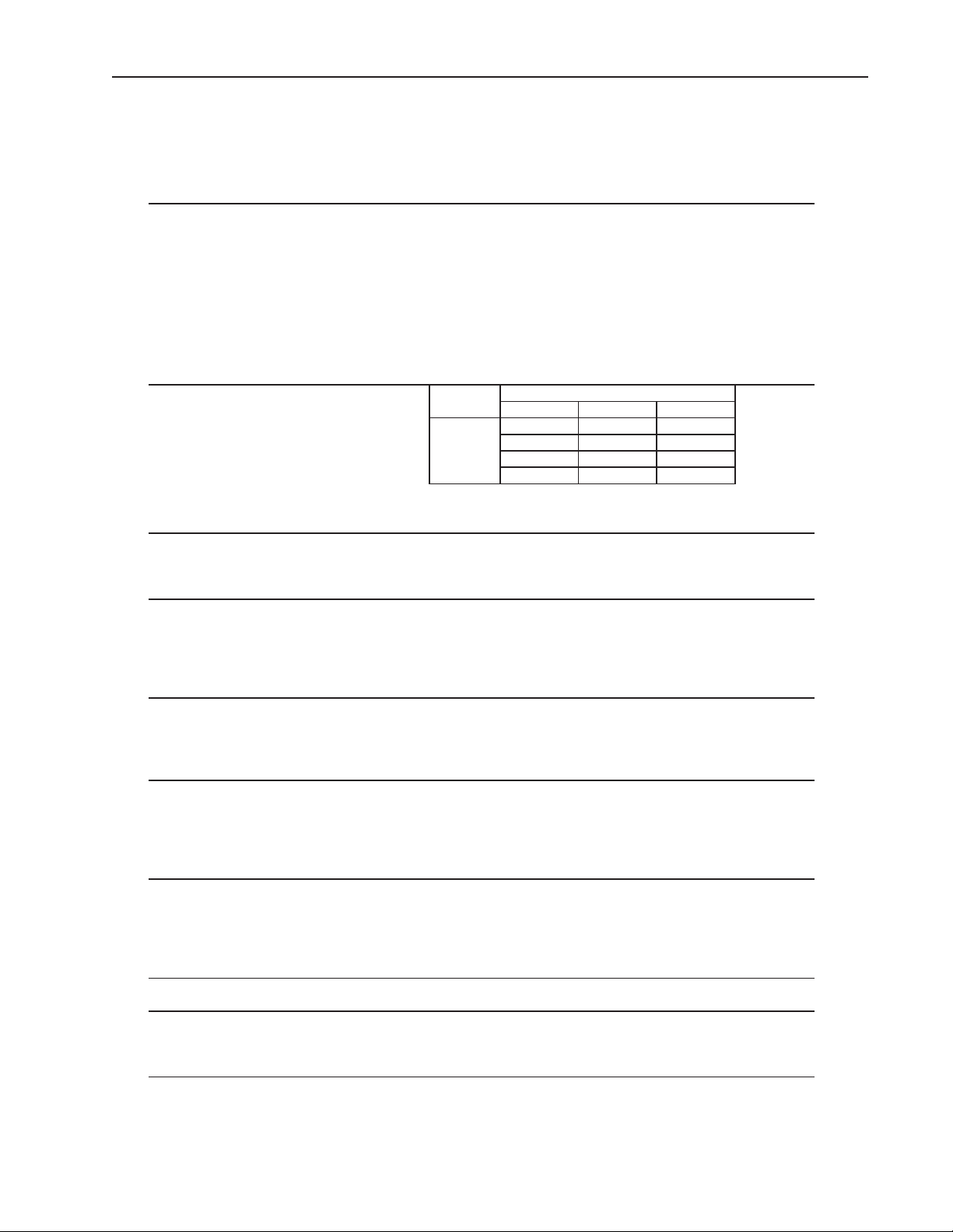
1. DCM-500BAH
AC SUPPLY VOLTAGE 115/60/1
COMPRESSOR 120 V 7.9 RLA 51 LRA
GEAR MOTOR 120 V 2.4 FLA 1/4 HP
FAN MOTOR 120 V 1.0 FLA 50 W
AGITATING MOTOR 120 V 0.9 FLA 55 W
DISPENSING MOTOR 120 V 0.9 FLA 55 W
OTHERS 120 V 0.2 A
MAXIMUM FUSE SIZE 20 A
MAX. HACR BREAKER (USA ONLY) 20 A
MAX. CIRC. BREAKER (CANADA ONLY) 20 A
MINIMUM CIRCUIT AMPACITY 20 A
APPROXIMATE ICE PRODUCTION Ambient WATER TEMP. (°F)
PER 24 HR. Temp. (°F) 50 70 90
lbs./day ( kg/day ) 70 *535 (243) 510 (231) 485 (220)
Reference without * marks 80 461 (209) 438 (199) 416 (189)
90 396 (179) *385 (175) 358 (162)
100 340 (154) 323 (147) *304 (138)
SHAPE OF ICE Cubelet (Compressed Flake Ice)
ICE QUALITY Apprx. 90% Ice (90/70° F, CONDUCTIVITY 200 µs/cm)
APPROXIMATE STORAGE CAPACITY 40 lbs.
ELECTRIC & WATER CONSUMPTION 90/70°F 70/50°F
ELECTRIC W (kWH/100 lbs.) 1055 (6.6) 985 (4.4)
POTABLE WATER 46 (11.9) 64 (11.9)
gal./24HR (gal./100 lbs.)
EXTERIOR DIMENSIONS (WxDxH) 26" x 22-1/2" x 40" ( 661 x 571 x 1016 mm)
EXTERIOR FINISH Stainless Steel, Galvanized Steel (Rear)
WEIGHT NET 251 lbs. (114 kg), Shipping 276 lbs. (125 kg)
CONNECTIONS - ELECTRIC Permanent Connection
- WATER SUPPLY Inlet 1/2" FPT
- DRAIN Outlet 3/4" FPT x2
ICE MAKING SYSTEM Auger type
HARVESTING SYSTEM Direct Driven Auger ( 1/4 HP Gear Motor )
ICE MAKING WATER CONTROL Float Switch
COOLING WATER CONTROL N/A
BIN CONTROL SYSTEM Mechanical Bin Control ( Proximity Sw. )
COMPRESSOR Hermetic, Model RS43C2E-CAA-219
CONDENSER Air-cooled, Fin and tube type
EVAPORATOR Copper Tube on Cylinder
REFRIGERANT CONTROL Thermostatic Expansion Valve
REFRIGERANT CHARGE R404A 1 lb 4.1 oz. (570g)
DESIGN PRESSURE High 460 PSIG Low 290 PSIG
P.C. BOARD CIRCUIT PROTECTION High Voltage Cut-out Relay
COMPRESSOR PROTECTION Auto-reset Overload Protector
GEAR MOTOR PROTECTION Auto-reset Thermal Protector
Fuse
REFRIGERANT CIRCUIT PROTECTION Auto-reset High Pressure Control Switch
LOW WATER PROTECTION Float Switch and Timer
ACCESSORIES - SUPPLIED Spare Fuse
- REQUIRED Legs
OPERATING CONDITIONS VOLTAGE RANGE 104-127 V
AMBIENT TEMP. 45-100 F
WATER SUPPLY TEMP. 45-90 F
WATER SUPPLY PRESSURE 10-113 PSIG
Note: We reserve the right to make changes in specications and design without prior
notice.
5
Page 6
2. DCM-500BAH-OS
AC SUPPLY VOLTAGE 115/60/1
COMPRESSOR 120 V 7.9 RLA 51 LRA
GEAR MOTOR 120 V 1.6 FLA 1/6 HP
FAN MOTOR 120 V 0.6 FLA 30 W
AGITATING MOTOR 120 V 0.9 FLA 55 W
DISPENSING MOTOR 120 V 0.9 FLA 55 W
OTHERS 120 V 0.2 A
MAXIMUM FUSE SIZE 20 A
MAX. HACR BREAKER (USA ONLY) 20 A
MAX. CIRC. BREAKER (CANADA ONLY) 20 A
MINIMUM CIRCUIT AMPACITY 20 A
APPROXIMATE ICE PRODUCTION Ambient WATER TEMP. (°F)
PER 24 HR. Temp. (°F) 50 70 90
lbs./day ( kg/day ) 70 *525 (238) 510 (231) 485 (220)
Reference without * marks 80 461 (209) 438 (199) 416 (189)
90 396 (179) *385 (175) 358 (162)
100 340 (154) 323 (147) *304 (138)
SHAPE OF ICE Cubelet (Compressed Flake Ice)
ICE QUALITY Apprx. 90% Ice (90/70° F, CONDUCTIVITY 200 µs/cm)
APPROXIMATE STORAGE CAPACITY 40 lbs.
ELECTRIC & WATER CONSUMPTION 90/70°F 70/50°F
ELECTRIC W (kWH/100 lbs.) 1055 (6.6) 985 (4.4)
POTABLE WATER 46 (11.9) 64 (11.9)
gal./24HR (gal./100 lbs.)
EXTERIOR DIMENSIONS (WxDxH) 26" x 22-1/2" x 40" ( 661 x 571 x 1016 mm)
EXTERIOR FINISH Stainless Steel, Galvanized Steel (Rear)
WEIGHT NET 251 lbs. (114 kg), Shipping 276 lbs. (125 kg)
CONNECTIONS - ELECTRIC Permanent Connection
- WATER SUPPLY Inlet 1/2" FPT
- DRAIN Outlet 3/4" FPT x2
ICE MAKING SYSTEM Auger type
HARVESTING SYSTEM Direct Driven Auger ( 1/6 HP Gear Motor )
ICE MAKING WATER CONTROL Float Switch
COOLING WATER CONTROL N/A
DISPENSER CONTROL SYSTEM Photoelectric Sensor (Infrared)
BIN CONTROL SYSTEM Mechanical Bin Control ( Proximity Sw. )
COMPRESSOR Hermetic, Model RS43C2E-CAA-219
CONDENSER Air-cooled, Fin and tube type
EVAPORATOR Copper Tube on Cylinder
REFRIGERANT CONTROL Thermostatic Expansion Valve
REFRIGERANT CHARGE R404A 1 lb 4.1 oz. (570g)
DESIGN PRESSURE High 460 PSIG Low 290 PSIG
P.C. BOARD CIRCUIT PROTECTION High Voltage Cut-out Relay
COMPRESSOR PROTECTION Auto-reset Overload Protector
GEAR MOTOR PROTECTION Auto-reset Thermal Protector
Fuse
REFRIGERANT CIRCUIT PROTECTION Auto-reset High Pressure Control Switch
LOW WATER PROTECTION Float Switch and Timer
ACCESSORIES - SUPPLIED Spare Fuse
- REQUIRED Legs
OPERATING CONDITIONS VOLTAGE RANGE 104-127 V
AMBIENT TEMP. 45-100 F
WATER SUPPLY TEMP. 45-90 F
WATER SUPPLY PRESSURE 10-113 PSIG
Note: We reserve the right to make changes in specications and design without prior
notice.
6
Page 7
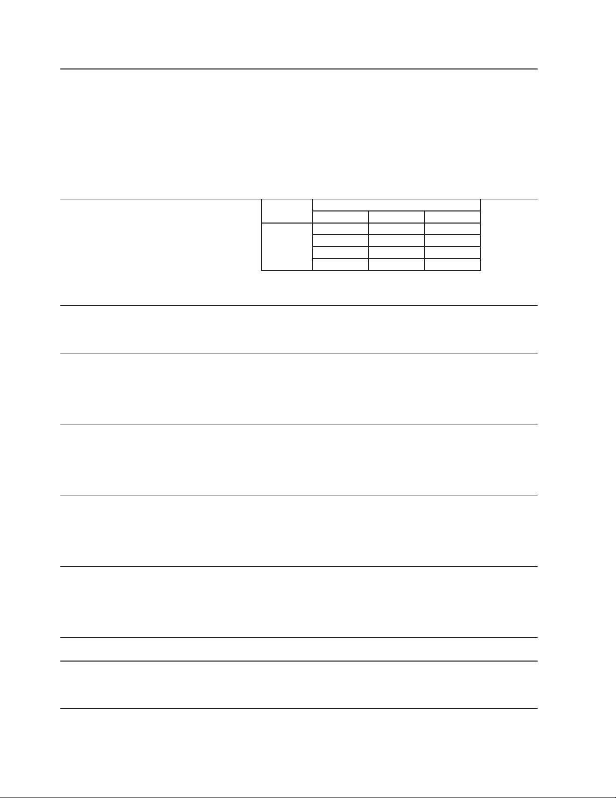
3. DCM-500BWH
)
AC SUPPLY VOLTAGE 115/60/1
COMPRESSOR 120 V 7.9 RLA 51 LRA
GEAR MOTOR 120 V 2.4 FLA 1/4 HP
AGITATING MOTOR 120 V 0.9 FLA 55 W
DISPENSING MOTOR 120 V 0.9 FLA 55 W
OTHERS 120 V 0.2 A
MAXIMUM FUSE SIZE 20 A
MAX. HACR BREAKER (USA ONLY) 20 A
MAX. CIRC. BREAKER (CANADA ONLY) 20 A
MINIMUM CIRCUIT AMPACITY 20 A
APPROXIMATE ICE PRODUCTION Ambient
PER 24 HR. Temp. (°F)
lbs./day ( kg/day ) 70 * 567 (257) 549 (249) 539 (244)
Reference without * marks 80 529 (240) 519 (2335
90 500 (227) * 495 (224) 481 (218)
100 472 (214) 464 (210) * 428 (194)
SHAPE OF ICE Cubelet (Compressed Flake Ice)
ICE QUALITY Approx. 90% Ice (90/70° F, Conductivity 200 µs/cm)
APPROXIMATE STORAGE CAPACITY 40 lbs.
ELECTRIC & WATER CONSUMPTION 90/70°F
ELECTRIC W (kWH/100 lbs.) 967 (4.7)
POTABLE WATER 60 (12)
WATER - COOLED CONDENSER 352 (71.2)
gal./24HR (gal./100 lbs.)
EXTERIOR DIMENSIONS (WxDxH) 26" x 22-1/2" x 40" (661 x 571 x 1016 mm)
EXTERIOR FINISH Stainless Steel, Galvanized Steel (Rear)
WEIGHT Net 245 lbs. (111 kg), Shipping 269 lbs. (122 kg)
CONNECTIONS - ELECTRIC Permanent Connection
- WATER SUPPLY Inlet 1/2" FPT Condenser Inlet 1/2"FPT
- DRAIN Outlet 3/4" FPT x2 Condenser Outlet 3/8" FPT
ICE MAKING SYSTEM Auger type
HARVESTING SYSTEM Direct Driven Auger ( 1/4 HP Gear Motor )
ICE MAKING WATER CONTROL Float Switch
COOLING WATER CONTROL Automatic Water Regulator
BIN CONTROL SYSTEM Mechanical Bin Control ( Proximity Sw. )
COMPRESSOR Hermetic, Model RS43C2E-CAA-219
CONDENSER Water Cooled, Double Tube Type
EVAPORATOR Copper Tube on Cylinder
REFRIGERANT CONTROL Thermostatic Expansion Valve
REFRIGERANT CHARGE R404A 14.1 oz. (400g)
DESIGN PRESSURE High 460 PSIG Low 290 PSIG
P.C. BOARD CIRCUIT PROTECTION High Voltage Cut-out Relay
COMPRESSOR PROTECTION Auto-reset Overload Protector
GEAR MOTOR PROTECTION Auto-reset Thermal Protector
Fuse
REFRIGERANT CIRCUIT PROTECTION Auto-reset High Pressure Control Switch
LOW WATER PROTECTION Float Switch and Timer
ACCESSORIES - SUPPLIED Spare Fuse
- REQUIRED Legs
OPERATING CONDITIONS VOLTAGE RANGE 104-127 V
AMBIENT TEMP. 45-100°F
WATER SUPPLY TEMP. 45-90°F
WATER SUPPLY PRESSURE 10-113 PSIG
991 (4.1)
251 (44.3)
WATER TEMP. (°F)
50 70 90
509 (231)
70/50°F
68 (12)
Note: We reserve the right to make changes in specications and design without prior
notice.
7
Page 8
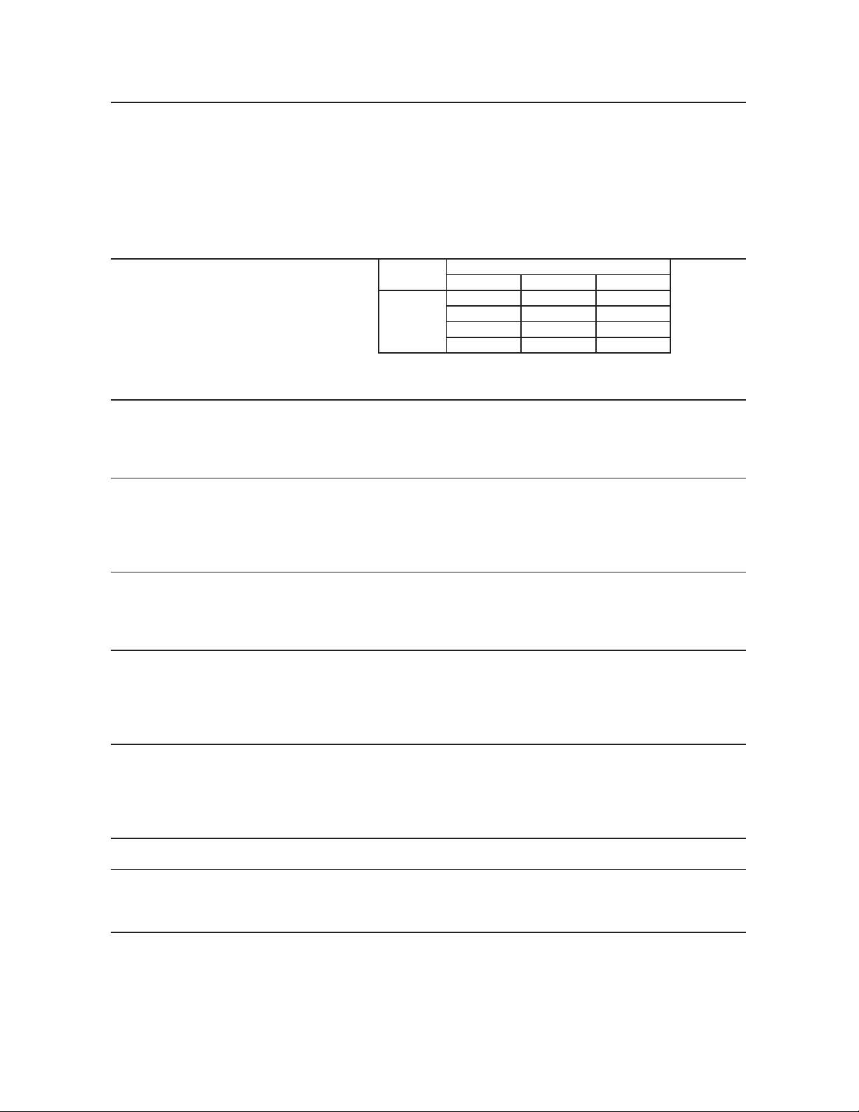
4. DCM-500BWH-OS
AC SUPPLY VOLTAGE 115/60/1
COMPRESSOR 120 V 7.9 RLA 51 LRA
GEAR MOTOR 120 V 1.6 FLA 1/6 HP
AGITATING MOTOR 120 V 0.9 FLA 55 W
DISPENSING MOTOR 120 V 0.9 FLA 55 W
OTHERS 120 V 0.2 A
MAXIMUM FUSE SIZE 20 A
MAX. HACR BREAKER (USA ONLY) 20 A
MAX. CIRC. BREAKER (CANADA ONLY) 20 A
MINIMUM CIRCUIT AMPACITY 20 A
APPROXIMATE ICE PRODUCTION Ambient
PER 24 HR. Temp. (°F)
lbs./day ( kg/day ) 70 * 567 257
Reference without * marks 80 529 240 519 235 509 231
90 500 227 * 495 224 481 218
100 472 214 464 210 * 428 194
SHAPE OF ICE Cubelet (Compressed Flake Ice)
ICE QUALITY Approx. 89% Ice (90/70° F, CONDUCTIVITY 200 µs/cm)
APPROXIMATE STORAGE CAPACITY 40 lbs.
ELECTRIC & WATER CONSUMPTION 90/70°F
ELECTRIC W (kWH/100 lbs.) 930 (4.8)
POTABLE WATER 56 (12)
WATER - COOLED CONDENSER 465 (100)
gal./24HR (gal./100 lbs.)
EXTERIOR DIMENSIONS (WxDxH) 26" x 22-1/2" x 40" (661 x 571 x 1016 mm)
EXTERIOR FINISH Stainless Steel, Galvanized Steel (Rear)
WEIGHT Net 245 lbs. (111 kg), Shipping 269 lbs. (122 kg)
CONNECTIONS - ELECTRIC Permanent Connection
- WATER SUPPLY Inlet 1/2" FPT Condenser Inlet 1/2"FPT
- DRAIN Outlet 3/4" FPT x2 Condenser Outlet 3/8" FPT
ICE MAKING SYSTEM Auger type
HARVESTING SYSTEM Direct Driven Auger ( 1/6 HP Gear Motor )
ICE MAKING WATER CONTROL Float Switch
COOLING WATER CONTROL Automatic Water Regulator
DISPENSE CONTROL SYSTEM Photoelectric Sensor (Infrared)
BIN CONTROL SYSTEM Mechanical Bin Control ( Proximity Sw. )
COMPRESSOR Hermetic, Model RS43C2E-CAA-219
CONDENSER Water Cooled, Double Tube Type
EVAPORATOR Copper Tube on Cylinder
REFRIGERANT CONTROL Thermostatic Expansion Valve
REFRIGERANT CHARGE R404A 14.1 oz. (400g)
DESIGN PRESSURE High 460 PSIG Low 290 PSIG
P.C. BOARD CIRCUIT PROTECTION High Voltage Cut-out Relay
COMPRESSOR PROTECTION Auto-reset Overload Protector
GEAR MOTOR PROTECTION Auto-reset Thermal Protector
Fuse
REFRIGERANT CIRCUIT PROTECTION Auto-reset High Pressure Control Switch
LOW WATER PROTECTION Float Switch and Timer
ACCESSORIES - SUPPLIED Spare Fuse
- REQUIRED Legs
OPERATING CONDITIONS VOLTAGE RANGE 104-127 V
AMBIENT TEMP. 45-100°F
WATER SUPPLY TEMP. 45-90°F
WATER SUPPLY PRESSURE 10-113 PSIG
70/50°F
985 (4.0)
285 (52)
WATER TEMP. (°F)
50 70 90
549 249 539 244
65 (12)
Note: We reserve the right to make changes in specications and design without prior
notice.
8
Page 9
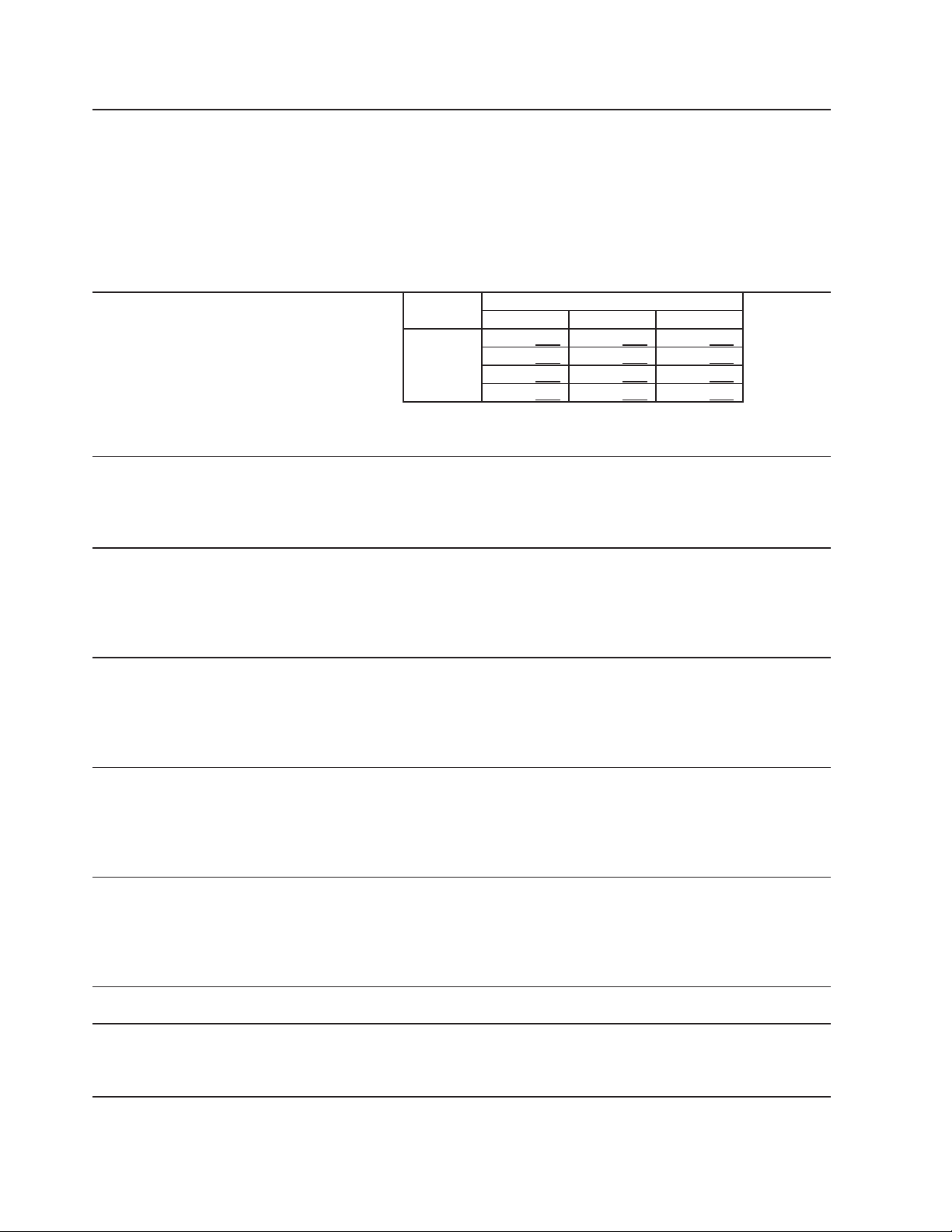
II. General Information
A. Construction
1. DCM-500BAH(-OS)
Expansion Valve
Evaporator Assembly
Inlet Water Valve
Float Switch
Reservoir
Control Box
Power Switch
Door Switch
Gear Motor
Spout A
Spout B
Drain Water Valve
Storage Bin
Agitator
Ice Dispensing
Auger
Control Switch
Dispense Mode Switch
Air-Cooled
Condenser
Shutter Assembly
Drier
Agitating Motor
Dispensing Motor
Compressor
Dispensing Water
Valve
Spout Cover
9
Page 10
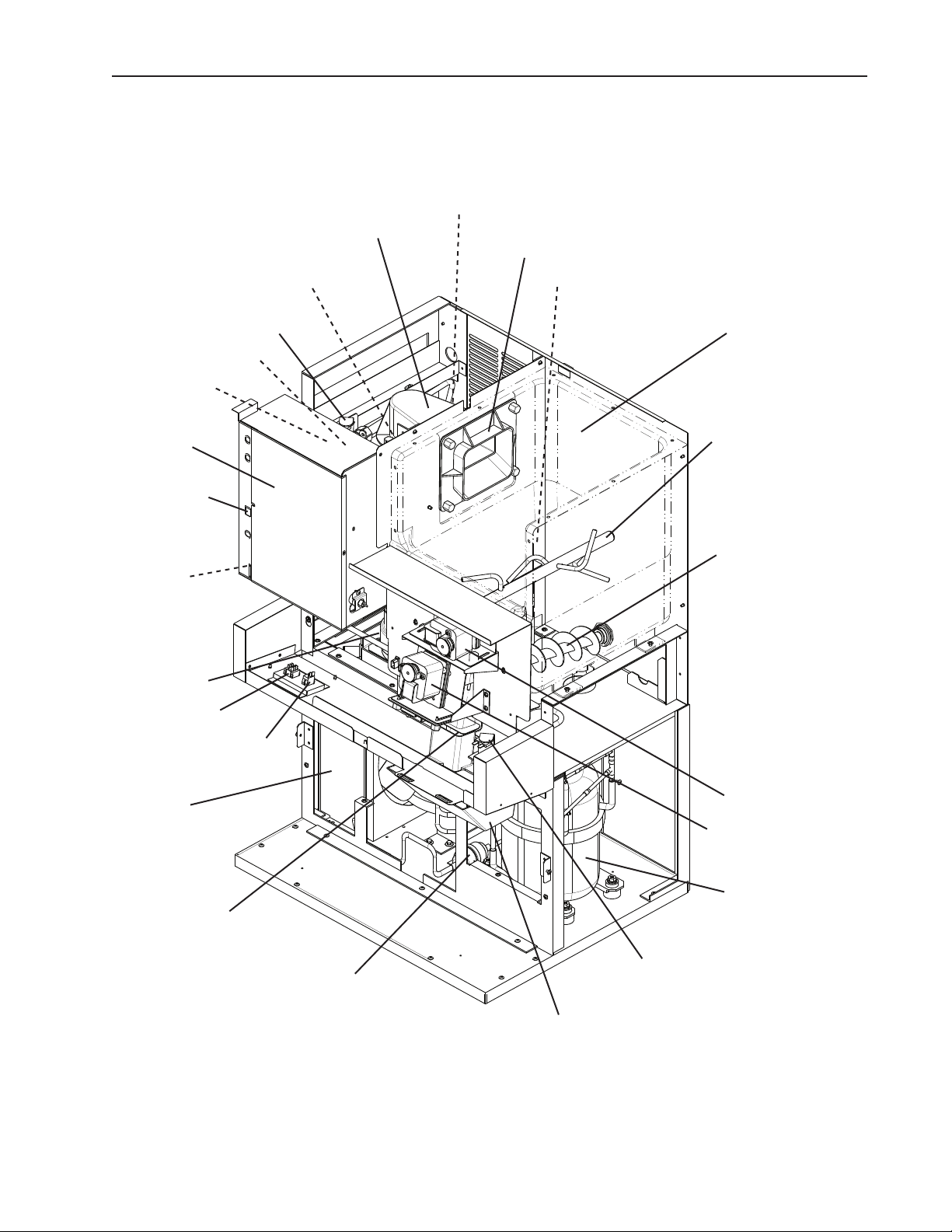
2. DCM-500BWH(-OS)
Inlet Water Valve
Reservoir
Control Box
Power Switch
Door Switch
Gear Motor
Spout A
Evaporator Assembly
Float Switch
Expansion Valve
Spout B
Drain Water Valve
Storage Bin
Agitator
Ice Dispensing
Auger
Control Switch
Dispense Mode Switch
Shutter Assembly
Water-Cooled
Condenser
Drier
Agitating Motor
Dispensing Motor
Compressor
Dispensing Water
Valve
Spout Cover
10
Page 11
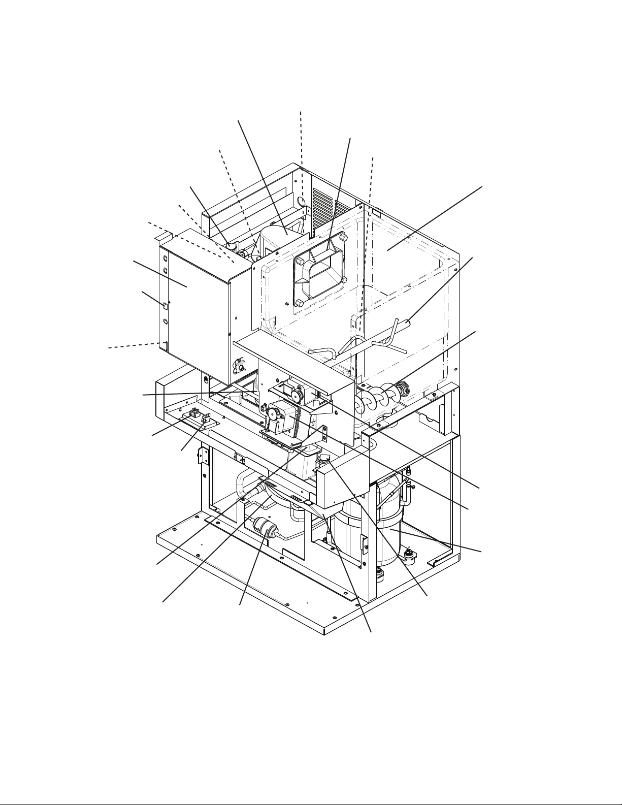
B. Ice Making Unit
1. DCM-500BAH(-OS), DCM-500BWH(-OS)
Extruding Head and
Upper Bearing
Auger
Cylinder
Evaporator
Insulation
Mechanical-Seal
Cubelet Cutter
Allen Head Cap Screw
Washer
Gear Motor
O-Ring
Spline Coupling
Allen Head Cap Screw
with Washer
Housing and
Lower Bearing
Hex Head Bolt
with Washer
11
Page 12

C. Sequence of Operation
The steps in the sequence are as outlined below. When power is supplied, the power
switch is in the "ON" position, the door switch is engaged, and the control switch is in the
"ICE" position, the "POWER" LED on the control board comes on.
1. Fill Cycle
WV opens and the reservoir lls with water until UF/S closes. Note: GM will not start
unless UF/S is closed. For details, see "IV. Service Diagnosis".
2. Ice Purge Cycle (60 seconds)
"GM" LED is on. WCR energizes, closing the low water safety circuit and de-energizing
the WV. GM and GMPR energize. GM runs for 60 seconds to clear any ice from the
evaporator.
3. Freeze Cycle
"COMP", "GM" LEDs are on. Comp and FMS energize. As the water in the evaporator
cools, ice starts forming within 4 to 6 minutes. This time frame depends on the inlet water
and ambient temperature conditions. UF/S and LF/S operate WV as needed to continue
the ice making process. This continues until BC shuts the icemaker down or power is
turned off to the icemaker.
4. Drain Cycle
12 hour DT activates, "FLUSH" LED is on after 150 second shutdown sequence. Comp
and FMS de-energize 90 seconds after the 12 hour DT activates, GMPR and GM
de-energize 60 seconds later. DV then energizes and remains energized for 20 minutes.
5. Shutdown
BC is activated and a 150 second shutdown sequence begins. After BC has been
open for 90 seconds, Comp and FMS de-energize, AM energizes for 0.6 seconds, and
60 seconds later GM de-energizes.
Legend: AM–agitating motor; BC–bin control; Comp–compressor; DT–drain timer;
FMS–self-contained fan motor; GM–gear motor; GMPR–gear motor protect
relay; LF/S–lower oat switch; UF/S–upper oat switch; WCR–water control
relay; WV–inlet water valve
12
Page 13

Low Water Safety
If rell > 90 sec. FT, 150 second
shutdown sequence begins
150 sec. Shutdown Sequence
Rell
(90 seconds)
3. Freeze Cycle
GM off
60 seconds
Comp off
90 seconds
UF/S open
LF/S closed
UF/S open
GMPR off
WV continues until
UF/S closes
FMS off
WV continues
GM continues
GMPR continues
FT exceeded
Comp continues
FMS continues
GM continues
GMPR continues
UF/S closed (WV off)
WCR on
FT off (90 sec.)
WV off
Comp continues
LF/S open (WV on)
WCR off
FT started (90 sec.)
WV on
Comp continues
WV continues
FMS continues
FMS continues
GM continues
GM continues
GMPR continues
GMPR continues
4. Ice Level Lowered
3. Icemaker is Off
See "1. Fill Cycle" above
Legend:
BC - bin control
Comp - compressor
DC - drain cycle
DT - drain timer
DV - drain valve
FMS - self-contained fan motor
4. 12 hour DC - Restart
See "1. Fill Cycle" above
3. Drain Cycle
DV on for 20 minutes
FT - ll timer (low water safety)
GM - gear motor
BC closedor20 Min. DT off (DC only)
GM off
GMPR off
GMPR - gear motor protect relay
DV on (DC only)
LF/S - lower oat switch
UF/S - upper oat switch
DV off (DC only)
12 hour DT reset (DC only)
WCR - water control relay
WV - inlet water valve
DCM-500BAH(-OS), DCM-500BWH(-OS) Sequence Flow Chart and Component Operation
60 seconds
Comp on
FMS on
WCR continues
GM continues
GMPR continues
4. 12 Hour Drain Cycle
DV opens for 20 minutes every 12 hours
See "3. 12 Hour Drain Cycle" below.
2. Ice Purge Cycle
1. Fill Cycle
60 seconds
WV on
LF/S closed
UF/S closed (WV off)
UF/S open
WCR on
WV off
GM on
GMPR on
2. Ice Purge Cycle
150 seconds
1. Bin Full
2. Ice Purge Cycle
90 seconds
1. Drain Cycle initiates
Comp off
FMS off
GM continues
GMPR continues
BC open or DC starts
Comp continues
FMS continues
GM continues
GMPR continues
Components Energized when the Control Switch is in the "DRAIN" Position
The "DRAIN" position on the control switch is used when cleaning and sanitizing the unit. This allows
cleaner and sanitizer to drain from the reservoir and evaporator assembly. When switching to the "DRAIN"
position during the freeze cycle, the drain valve does not energize until the 150 second shutdown sequence
terminates (2. Shutdown & Restart).
Note: To bypass the 150 second shutdown sequence, move the power switch to the "OFF" position, place the
control switch in the "DRAIN" position, then move the power switch back to the "ON" position.
Shutdown & Restart
1. Startup
Power switch "ON"
Control switch in "ICE"
2. Shutdown & Restart
3. 12 Hour Drain Cycle
13
Page 14

D. Control Board
• A Hoshizaki exclusive solid-state control board is employed in DCM-500BAH,
DCM-500BAH-OS, DCM-500BWH, and DCM-500BWH-OS Cubelet Icemaker /
Dispensers.
• All models are pretested and factory-adjusted.
CAUTION
1. Fragile, handle very carefully.
2. The control board contains integrated circuits, which are susceptible to
failure due to static discharge. It is especially important to touch the metal
part of the unit before handling or replacing the board.
3. Do not touch the electronic devices on the control board or the back of the
control board to prevent damage to the control board.
4. Do not change wiring and connections. Especially, never misconnect
terminals.
5. Always replace the whole control board if it goes bad.
6. Do not short out power supply to test for voltage.
14
Page 15
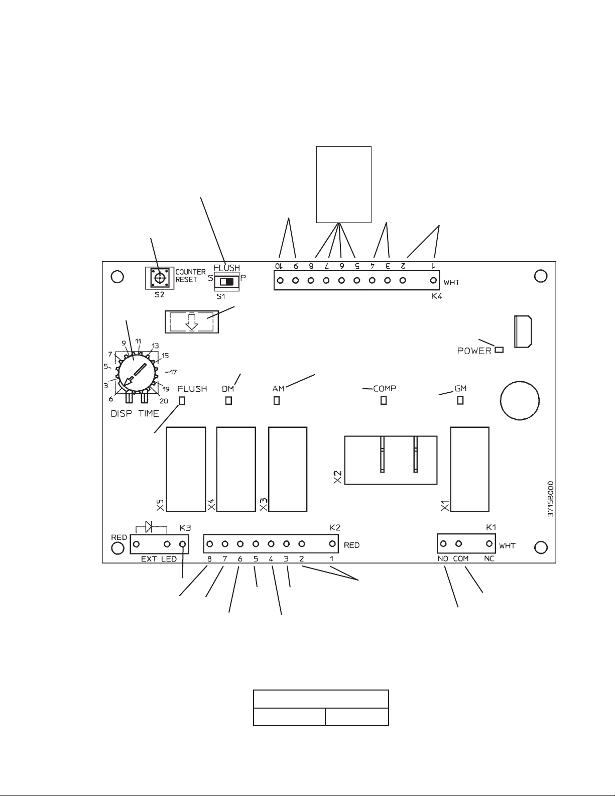
1. Control Board Layout
a) DCM-500BAH, DCM-500BWH
Flush Switch
Must be left in the "P" position,
otherwise the internal drain
timer will not operate.
Counter Reset Button (not
used in this application)
High
Pressure
Switch
Dispensing
Components
See "III.
B. Wiring
Diagrams"
for details.
Bin Control,
Control
Switch,
Low Water
Safety
10.5V
Transformer
Portion Control
Timer
"FLUSH" LED
(X5 Relay)
Drain Valve
24V Supply Out
Drain Valve
24V Out
Microprocessor (board revision level
indicated by last 2 digits on label)
"DM" LED
(X4 Relay)
Shutter Solenoid,
Dispensing Auger
Motor
115V In
24V In
Dispensing Motor
115V Out
"AM" LED
(X3 Relay)
Agitating Motor
"COMP" LED
(X2 Relay)
Compressor,
Fan Motor
115V In
Agitating Motor
115V Out
"GM" LED
(X1 Relay)
Gear Motor
Gear Motor
Protect Relay
Circuit
"POWER" LED
(lights when
power is supplied
to the board)
115V In
Gear Motor
115V Out
Control Board
Part Number 2A1592-01
15
Page 16
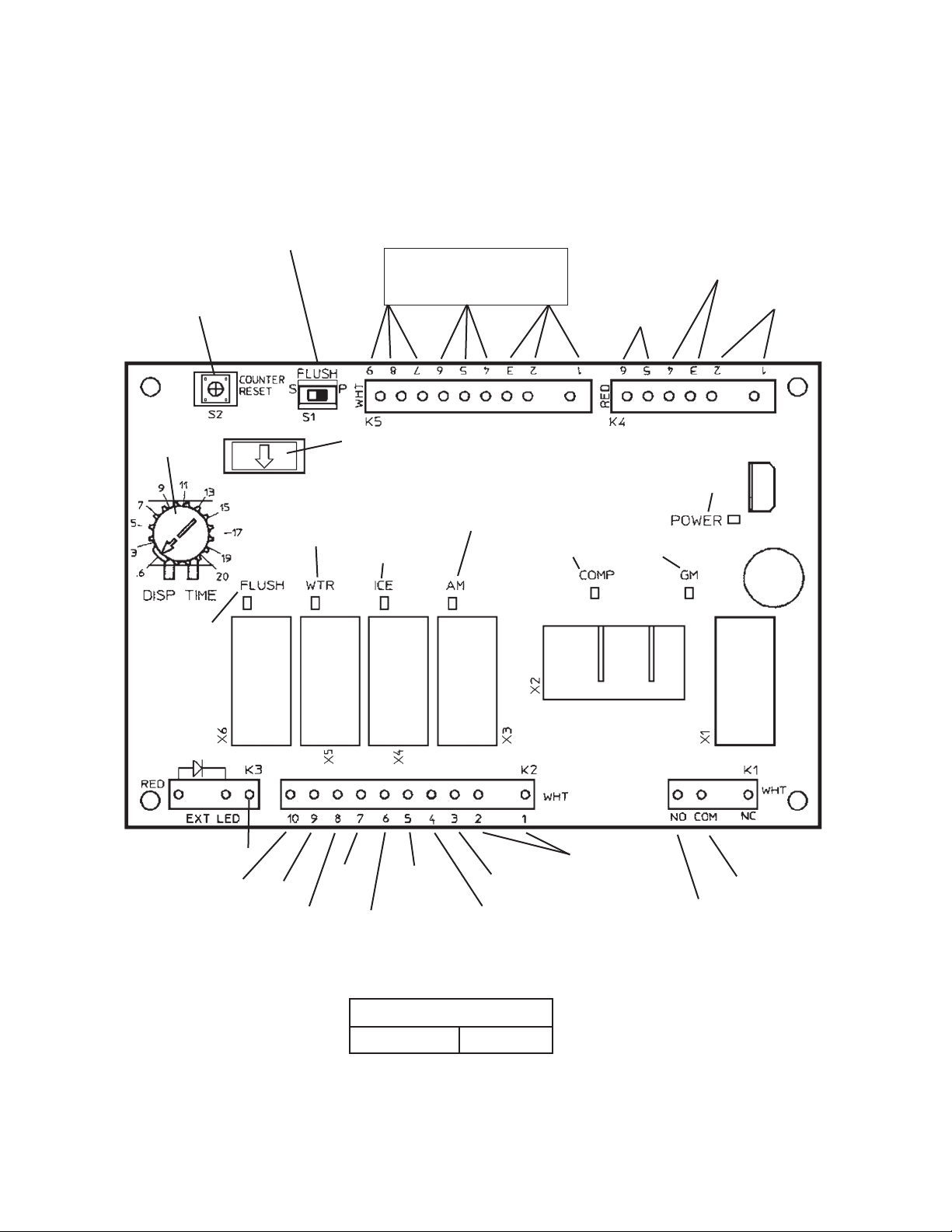
b) DCM-500BAH-OS, DCM-500BWH-OS
Flush Switch
Must be left in the "P" position,
otherwise the internal drain
timer will not operate.
Counter Reset Button (not
used in this application)
Dispensing Components
See "III.B. Wiring Diagrams"
for details.
Bin Control,
Control Switch,
Low Water Safety
High
Pressure
Switch
10.5V
Transformer
Portion Control
Timer
"FLUSH" LED
(X6 Relay)
Drain Valve
24V Supply Out
Drain Valve
24V Out
"WTR" LED
(X5 Relay)
Dispensing
Water Valve
24V In
Dispensing
Water Valve
24V Out
Microprocessor (board revision level
indicated by last 2 digits on label)
"ICE" LED
(X4 Relay)
Shutter Solenoid,
Dispensing Auger
Motor
24V In
Dispensing Motor
115V Out
115V In
"AM" LED
(X3 Relay)
Agitating Motor
"COMP" LED
(X2 Relay)
Compressor,
Fan Motor
115V In
Agitating Motor
115V Out
"POWER" LED
(lights when
power is supplied
to the board)
"GM" LED
(X1 Relay)
Gear Motor
Gear Motor
Protect Relay
Circuit
115V In
Gear Motor
115V Out
Control Board
Part Number 2A2649-01
16
Page 17
2. Features
The control board provides the following safeguards:
•Provides component protection during low water supply.
•Purges remaining ice in the evaporator at startup and shutdown.
•Providesshortcycleprotectionforthecompressor.
a) LED Lights
The "POWER" LED indicates control voltage and will remain on unless a control
voltage problem occurs. An LED illuminates for each relay as it is energized. For more
information, see "II.C. Sequence of Operation."
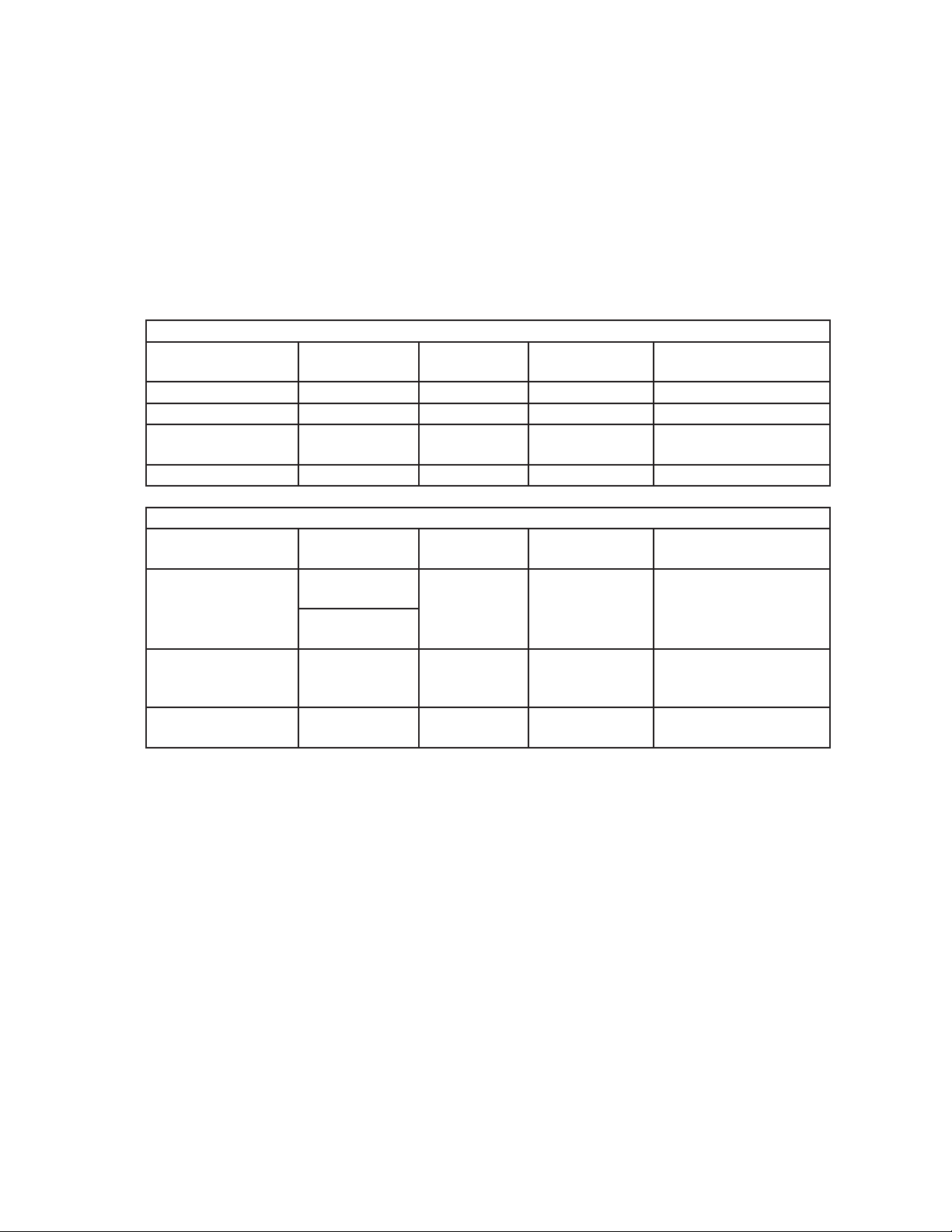
Icemaking
Cycle (Relay) LED
Fill POWER only WV N/A As Needed
Ice Purge (X1) GM GM 60 seconds N/A
Freeze (X1, X2) GM, COMP
Drain Valve (X6) FLUSH DV 20 Minutes Every 12 Hours
Relay LED
Push Button
Ice Dispense (X4)
Agitating Motor (X3) AM AM .6 seconds
Water Dispense (X5)
(Opti Serv Only)
DM
Opti Serv
ICE
WTR WTR N/A N/A
Energized
Components
GM, Comp,
FMS
Dispensing
Energized
Component
IDM
Time LEDs are OnFrequency LEDs are
On
N/A N/A
Time LEDs are OnFrequency LEDs are
On
60 seconds
maximum
N/A
Every 12 seconds of
accumulative dispense
time
Legend: AM–agitating motor, Comp–compressor; DV–drain valve; FMS–self-contained
fan motor; GM–gear motor; IDM–ice dispensing motor, shutter solenoid;
WTR–dispensing water valve; WV–inlet water valve
17
Page 18
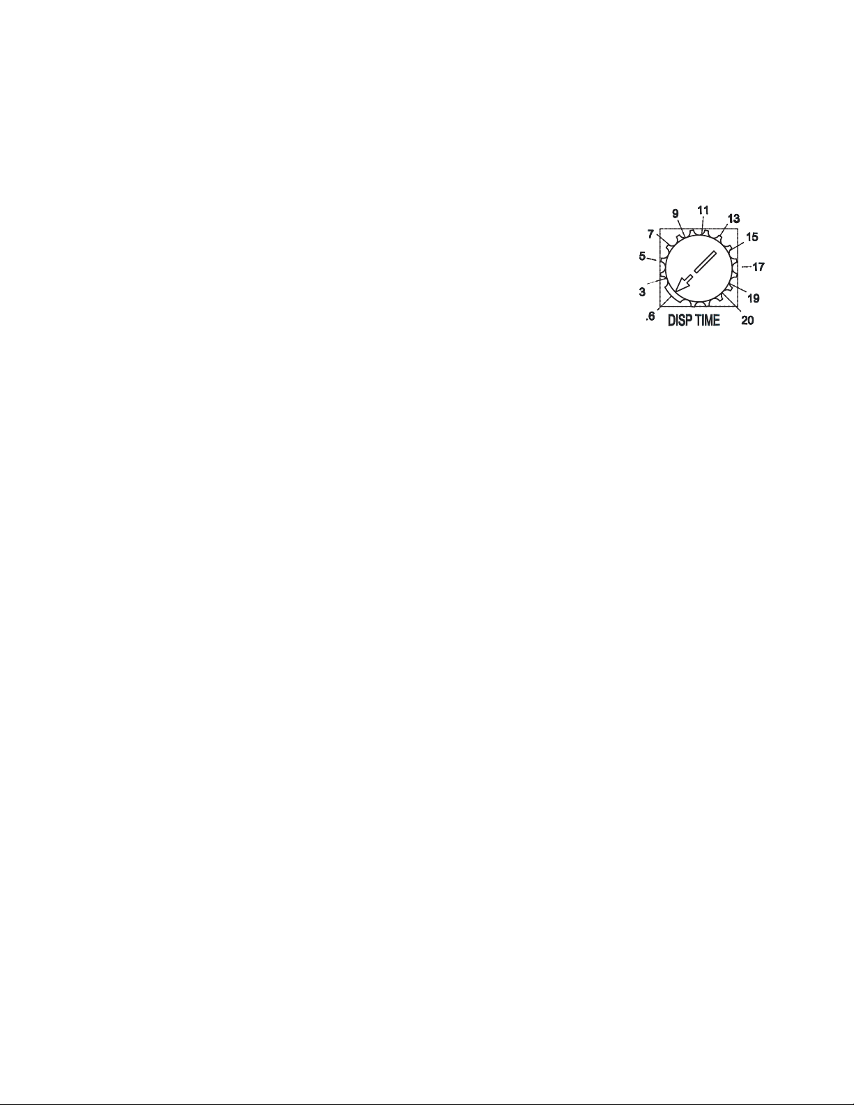
3. Controls and Adjustments
a) Portion Control
When the dispense mode switch is placed in the "PORTION" position, a variable resistor
(located on the control board) controls the ice dispense time.
The gures on the label indicate dispensing time (sec.). When shipped, the portion
control is set at the minimum dispensing time (0.6 sec.).
DCM-500BAH(-OS), DCM-500BWH(-OS). . . . . . .Approximately 0.72 oz.
Amount of ice dispensed per second.
DCM-500BAH(-OS), DCM-500BWH(-OS) . . . . . . Approximately 1.2 oz.
4. Control Board Check Procedure
Before replacing a control board that does not show a visible defect and that you suspect
is bad, always conduct the following check procedure. This procedure will help you verify
your diagnosis.
a) Power Supply
1. Move the control switch to the "ICE" position. The "POWER" LED should come on.
If the "POWER" LED is off, check that the power supply is on, the power switch is
in the "ON" position, the door switch is engaged, and the control switch is in the
"ICE" position. Check the transformer 10.5V secondary circuit and fuse. If the 10.5V
secondary circuit (K4 pins 1 and 2) has proper voltage and the "POWER" LED is off,
the control board is bad and should be replaced.
If the secondary circuit does not have proper voltage, see "IV.C.1.[1] The icemaker will
not start (Fill Cycle)" for further details.
b) Ice Making Components
1. Conrm the reservoir is full of water. If no water is in the reservoir, make sure that the
control switch is not in the "DRAIN" position and that the unit is not in the 12 hour drain
cycle. Also check the water supply line, water shutoff valve, and water lters. In the ll
cycle, the "POWER" LED is the only LED lit on the control board. If no water is lling
the reservoir, check for 24V at connector K2 terminal 7 to neutral and connector K3
(DBU) to neutral. If there is 24V at connector K2 terminal 7 to neutral and no voltage at
K3 (DBU) to neutral, the control board is bad and should be replaced. See "IV.C.1.[1]
The icemaker will not start (Fill Cycle)" for further details.
2. When the reservoir is full, the "GM" LED comes on and the gear motor starts. If
the "GM" LED does not come on or the gear motor does not start, check that the
following safety circuits are closed: a) high pressure switch (DCM-500BAH and DCM500BWH, connector K4 terminals 9 and 10, DCM-500BAH-OS and DCM-500BWH-OS,
connector K4 terminals 5 and 6), b) low water safety/bin control/ice making switch
circuit (connector K4 terminals 3 and 4). Next, check for 115/120V at connector K1
"COM" and K1 "NO" on the control board to neutral. If the "GM" LED is on and there is
voltage at K1 "COM" to neutral and no voltage at K1 "NO" to neutral, the control board
is bad and should be replaced. See wiring diagram "III.C.2. Ice Purge Cycle" for further
details.
18
Page 19

3. 60 seconds after the "GM" LED comes on, the "COMP" LED comes on, and the
compressor and fan motor start. If the "COMP" LED does not come on 60 seconds
after the gear motor starts, check that the gear motor protect relay contacts (connector
K2 terminals 1 and 2) have closed. If the "COMP" LED is on and the compressor and
fan motor did not start, check for 115/120V at X2 (LBU) and X2 (BR) on the control
board to neutral. If the "COMP" LED is on and there is voltage at X2 (BR) to neutral
and no voltage at X2 (LBU) to neutral, the control board is bad and should be replaced.
See wiring diagram "III.C.3. Freeze Cycle" for further details.
c) Dispensing Components DCM-500BAH, DCM-500BWH
1. Ice Dispense "Continuous": Pressing the ice dispense switch closes terminals 6 and 5
at the K4 connector. The "DM" LED comes on and the dispensing motor energizes. If
the "DM" LED does not turn on, check continuity through the ice dispense switch and
the dispense mode switch. If the LED is on and the dispensing motor does not start,
check for 115/120V at connector K2 terminals 3 and 6 to a neutral. With voltage at
terminal 3 and not at terminal 6, the control board is bad and should be replaced.
Note: The agitating motor will operate .6 seconds every 12 seconds of accumulative
dispense time. See "III.D.1. Continuous Dispense."
2. Ice Dispense "Portion": Pressing the ice dispense switch closes terminals 6 and 7 at
the K4 connector. The "DM" LED comes on and the dispinsing motor energizes. If the
"DM" LED does not turn on, check continuity through the ice dispense switch and the
dispense mode switch. If the LED is on and the dispensing motor does not start, check
for 115V at connector K2 terminals 3 and 6 to a neutral. With voltage at terminal 3 and
not at terminal 6, the control board is bad and should be replaced.
Note: The agitating motor will operate .6 seconds every 12 seconds of accumulative
dispense time. See "III.D.2. Portion Dipsense."
d) Dispensing Components DCM-500BAH-OS, DCM-500BWH-OS
See "IV.C.5. Opti Serve (OS) Sensors."
19
Page 20

E. Float Switch
Depending on local water conditions, scale may build up on the oat switch. Scale on the
switch can cause the oats to stick. In this case, the oat switch should be cleaned and
checked.
First, remove the switch from the water tank. Soak the switch assembly in ice machine
cleaner. While not necessary, the oats can be removed from the shaft during cleaning.
If you remove them, note that the blue oat is on top. The oats must be installed with
the magnets inside them towards the top of the switch. Installing the oats upside down
will affect the timing of the oat switch operation. Once clean, rinse and wipe the cleaner
off. Next, check the switch with an ohm meter. This oat switch has three wires (the
black wire is common) and two separate switches. Check the upper switch by ohming
out the black and red wires. When the oat is up, the switch should be closed. Check the
lower switch by ohming out the black and blue wires in the same manner. If either switch
fails, the assembly should be replaced.
Red (upper)
Black (common)
Blue (lower)
Magnet (towards top)
Upper Float (blue)
Spring Retainer Clip
Magnet (towards top)
Lower Float (white)
Plastic Retainer Clip
20
Page 21
III. Technical Information
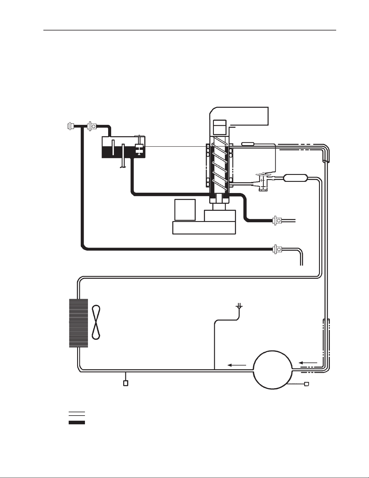
A. Water Circuit and Refrigeration Circuit
1. DCM-500BAH(-OS)
Water Supply
Inlet
Water
Val ve
Reservoir
Float Switch
Overow
Water Level
Evaporator
Gear Motor
Spout
Drier
Expansion
Val ve
To Drain
Drain
Val ve
Dispensing
Water Valve
Fan
Air-Cooled
Condenser
Access
Val ve
Refrigeration Circuit
Water Circuit
21
High
Pressure
Switch
Compressor
Access
Val ve
Page 22

2. DCM-500BWH(-OS)
Water Supply
Inlet
Water
Val ve
Reservoir
Overow
Float Switch
Water Level
Evaporator
Gear Motor
Spout
Drier
Expansion
Val ve
To Drain
Drain
Val ve
Dispensing
Water Valve
Water Supply In
Water Supply Out
Water Regulating
Val ve
Water-Cooled
Condenser
Refrigeration Circuit
Water Circuit
Access
Val ve
22
High
Pressure
Switch
Compressor
Access
Val ve
Page 23

B. Wiring Diagrams
1. DCM-500BAH, DCM-500BWH
WIRE COLOR CODE
BK BLACK
BR BROWN
BU BLUE
DBU DARK BLUE
GY GRAY
LBU LIGHT BLUE
O ORANGE
P PINK
R RED
V VIOLET
W WHITE
Y YELLOW
W/BK WHITE/BLACK
W/BR WHITE/BROWN
W/BU WHITE/BLUE
W/O WHITE/ORANGE
W/R WHITE/RED
(Control Board)
*
* High Pressure Switch
Air-Cooled Model Water-Cooled Model
21
Cut-out 412±
PSIG 384±21 PSIG
0
Cut-in 327±21 PSIG 284±21 PSIG
23
0
Page 24

2. DCM-500BAH-OS, DCM-500BWH-OS
WIRE COLOR CODE
BK BLACK
BR BROWN
BU BLUE
DBU DARK BLUE
GY GRAY
LBU LIGHT BLUE
O ORANGE
P PINK
R RED
V VIOLET
W WHITE
Y YELLOW
W/BK WHITE/BLACK
W/BR WHITE/BROWN
W/BU WHITE/BLUE
W/O WHITE/ORANGE
W/R WHITE/RED
(Control Board)
*
* High Pressure Switch
Air-Cooled Model Water-Cooled Model
21
Cut-out 412±
PSIG 384±21 PSIG
0
0
Cut-in 327±21 PSIG 284±21 PSIG
24
Page 25

C. Sequence of Electrical Circuit – Ice Making
1. Fill Cycle
With the power switch in the "ON" position and the control switch in the "ICE" position,
the inlet water valve energizes and the reservoir lls with water until the upper oat
switch closes.
DCM-500BAH
DCM-500BWH
DCM-500BAH-OS
DCM-500BWH-OS
(Control Board)
WIRE COLOR CODE
BK BLACK O ORANGE W/BK WHITE/BLACK
BR BROWN P PINK W/BR WHITE/BROWN
BU BLUE R RED W/BU WHITE/BLUE
DBU DARK BLUE V VIOLET W/O WHITE/ORANGE
GY GRAY W WHITE W/R WHITE/RED
LBU LIGHT BLUE Y YELLOW
25
(Control Board)
Page 26

2. Ice Purge Cycle
Upper oat switch closes, water control relay energizes, inlet water valve closes, gear
motor starts, gear motor protect relay energizes.
DCM-500BAH
DCM-500BWH
DCM-500BAH-OS
DCM-500BWH-OS
(Control Board)
WIRE COLOR CODE
BK BLACK O ORANGE W/BK WHITE/BLACK
BR BROWN P PINK W/BR WHITE/BROWN
BU BLUE R RED W/BU WHITE/BLUE
DBU DARK BLUE V VIOLET W/O WHITE/ORANGE
GY GRAY W WHITE W/R WHITE/RED
LBU LIGHT BLUE Y YELLOW
26
(Control Board)
Page 27

3. Freeze Cycle
Compressor and fan motor start 60 seconds after gear motor starts.
DCM-500BAH
DCM-500BWH
DCM-500BAH-OS
DCM-500BWH-OS
(Control Board)
WIRE COLOR CODE
BK BLACK O ORANGE W/BK WHITE/BLACK
BR BROWN P PINK W/BR WHITE/BROWN
BU BLUE R RED W/BU WHITE/BLUE
DBU DARK BLUE V VIOLET W/O WHITE/ORANGE
GY GRAY W WHITE W/R WHITE/RED
LBU LIGHT BLUE Y YELLOW
27
(Control Board)
Page 28

4. 12 Hour Drain Cycle / Drain Switch
12 hour timer initiates cycle or the control switch is moved to the "DRAIN" position.
90 seconds after initiation, the compressor and condenser fan motor stop, 60 seconds
later the gear motor stops. Once the gear motor protect relay de-energizes, the drain
water valve opens. In the 12 hour drain cycle, the drain water valve remains open for
20 minutes. When the drain cycle is initiated manually using the control switch, the drain
valve remains open until the control switch is moved to the "ICE" position.
DCM-500BAH
DCM-500BWH
DCM-500BAH-OS
DCM-500BWH-OS
12 Hour Drain Cycle
Manual Drain Cycle
(Control Board)
WIRE COLOR CODE
BK BLACK O ORANGE W/BK WHITE/BLACK
BR BROWN P PINK W/BR WHITE/BROWN
BU BLUE R RED W/BU WHITE/BLUE
DBU DARK BLUE V VIOLET W/O WHITE/ORANGE
GY GRAY W WHITE W/R WHITE/RED
LBU LIGHT BLUE Y YELLOW
28
12 Hour Drain Cycle
Manual Drain Cycle
(Control Board)
Page 29

5. Shutdown
The bin control switch is activated and a 150 second shutdown sequence begins. After
the bin control has been open for 90 seconds, the compressor and fan motor stop, the
agitating motor operates for 0.6 seconds, and 60 seconds later the gear motor stops.
DCM-500BAH
DCM-500BWH
DCM-500BAH-OS
DCM-500BWH-OS
(Control Board)
WIRE COLOR CODE
BK BLACK O ORANGE W/BK WHITE/BLACK
BR BROWN P PINK W/BR WHITE/BROWN
BU BLUE R RED W/BU WHITE/BLUE
DBU DARK BLUE V VIOLET W/O WHITE/ORANGE
GY GRAY W WHITE W/R WHITE/RED
LBU LIGHT BLUE Y YELLOW
29
(Control Board)
Page 30

6. Low Water Safety
Upper oat switch fails to close within 90 seconds after the lower oat switch opens, the
150 second shutdown sequence begins. The inlet water valve remains open until the
upper oat switch closes.
DCM-500BAH
DCM-500BWH
DCM-500BAH-OS
DCM-500BWH-OS
(Control Board)
WIRE COLOR CODE
BK BLACK O ORANGE W/BK WHITE/BLACK
BR BROWN P PINK W/BR WHITE/BROWN
BU BLUE R RED W/BU WHITE/BLUE
DBU DARK BLUE V VIOLET W/O WHITE/ORANGE
GY GRAY W WHITE W/R WHITE/RED
LBU LIGHT BLUE Y YELLOW
30
(Control Board)
Page 31

7. High Pressure Switch
When the high pressure switch opens, the compressor stops immediately, 60 seconds
later the gear motor stops. To restart, allow time for the high pressure switch to close,
then move the power switch to the "OFF" position and then back to the "ON" position.
DCM-500BAH
DCM-500BWH
DCM-500BAH-OS
DCM-500BWH-OS
(Control Board)
WIRE COLOR CODE
BK BLACK O ORANGE W/BK WHITE/BLACK
BR BROWN P PINK W/BR WHITE/BROWN
BU BLUE R RED W/BU WHITE/BLUE
DBU DARK BLUE V VIOLET W/O WHITE/ORANGE
GY GRAY W WHITE W/R WHITE/RED
LBU LIGHT BLUE Y YELLOW
31
(Control Board)
Page 32

D. Sequence of Electrical Circuit – Dispensing
1. Continuous Dispense
Agitating motor energizes for .6 seconds for every 12 seconds of accumulative dispense
time. Maximum dispense time per dispense switch activation is 60 seconds. After
60 seconds, the dispense switch must be disengaged and engaged again.
DCM-500BAH
DCM-500BWH
DCM-500BAH-OS
DCM-500BWH-OS
(Control Board)
WIRE COLOR CODE
BK BLACK O ORANGE W/BK WHITE/BLACK
BR BROWN P PINK W/BR WHITE/BROWN
BU BLUE R RED W/BU WHITE/BLUE
DBU DARK BLUE V VIOLET W/O WHITE/ORANGE
GY GRAY W WHITE W/R WHITE/RED
LBU LIGHT BLUE Y YELLOW
32
(Control Board)
Page 33

2. Portion Dispense
Agitating motor energizes for .6 seconds for every 12 seconds of accumulative dispense
time. A variable resistor which controls the amount of ice dispensed is located on
the control board. The gures on the label indicate dispensing time (sec.). See "II.
D.3.a) Portion Control." When shipped, the portion control is set at the minimum
dispensing time (0.6 sec.).
DCM-500BAH(-OS), DCM-500BWH(-OS) . . . . . . . . . . . . Approximately 0.72 oz.
Amount of ice dispensed per second.
DCM-500BAH(-OS), DCM-500BWH(-OS) . . . . . . . . . . . . Approximately 1.2 oz.
DCM-500BAH
DCM-500BWH
DCM-500BAH-OS
DCM-500BWH-OS
(Control Board)
WIRE COLOR CODE
BK BLACK O ORANGE W/BK WHITE/BLACK
BR BROWN P PINK W/BR WHITE/BROWN
BU BLUE R RED W/BU WHITE/BLUE
DBU DARK BLUE V VIOLET W/O WHITE/ORANGE
GY GRAY W WHITE W/R WHITE/RED
LBU LIGHT BLUE Y YELLOW
33
(Control Board)
Page 34

E. Performance Data
2
2
1. DCM-500BAH(-OS)
APPROXIMATE Ambient Water Temp. (°F)
ICE PRODUCTION Temp. (°F)
PER 24 HR. 70 *535 (243) 510 (231) 485 (220)
80 461 (209) 438 (199) 416 (189)
90 396 (179) *385 (175) 358 (162)
lbs./day ( kg/day) 100 340 (154) 323 (147) *304 (138)
APPROXIMATE ELECTRIC 70 *985 -- 995 -- 1005 -CONSUMPTION 80 1015 -- 1025 -- 1035 --
90 1045 -- *1055 -- 1056 --
watts 100 1058 -- 1059 -- *1060 -APPROXIMATE WATER 70 *64 (243) 61 (231) 58 (220)
CONSUMPTION PER 24 HR. 80 55 (209) 53 (199) 50 (189)
90 48 (179) *46 (175) 43 (162)
gal. / day (l/day) 100 41 (154) 39 (147) *37 (138)
EVAPORATOR OUTLET TEMP. 70 *23 (-5) 23 (-5) 23 (-5)
°F (°C) 80 23 (-5) 26 (-4) 26 (-4)
90 26 (-4) *26 (-4) 28 (-3)
100 28 (-3) 28 (-3) *28 (-3)
HEAD PRESSURE 70 *230 (16.2) 230 (16.2) 230 (16.2)
80 264 (18.5) 264 (18.5) 264 (18.5)
90 297 (20.9) *297 (20.9) 297 (20.9)
PSIG (kg/cm
SUCTION PRESSURE 70 *33 (2.3) 33 (2.3) 33 (2.3)
PSIG (kg/cm
TOTAL HEAT OF REJECTION 6300 BTU/h (AT 90°F /WT 70°F)
G) 100 335 (23.5) 335 (23.5) *335 (23.5)
G) 80 35 (2.5) 35 (2.5) 35 (2.5)
90 37 (2.6) *37 (2.6) 37 (2.6)
100 43 (3.0) 43 (3.0) *43 (3.0)
50 70 90
Note:
1. The data without *marks should be used for reference only.
2. We reserve the right to make changes in specications and design without prior
notice.
34
Page 35

2. DCM-500BWH(-OS)
APPROXIMATE Ambient Water Temp. (°F)
ICE PRODUCTION Temp. (°F)
PER 24 HR. 70 * 567 257
80 529 240 519 235 509 231
90 500 227 * 495 224 481 218
lbs./day ( l/day) 100 472 214 464 210 * 428 194
APPROXIMATE ELECTRIC 70 * 976 -- 967 -- 991 -CONSUMPTION 80 976 -- 967 -- 991 --
90 976 -- * 967 -- 991 --
watts 100 976 -- 967 -- * 991 -APPROXIMATE WATER 70 * 111 0.51
CONSUMPTION PER 24 HR. 80 111 0.50 130 0.59 198 0.90
(TOTAL) 90 110 0.50 * 130 0.59 203 0.92
gal. / day (kl/day) 100 110 0.50 132 0.60 * 214 0.97
EVAPORATOR OUTLET TEMP. 70 * 19 -7 19 -7 19 -7
°F (°C) 80 19 -7 19 -7 19 -7
90 19 -7 * 19 -7 19 -7
100 19 -7 19 -7 * 19 -7
HEAD PRESSURE 70 * 266 18.7 267 18.8 270 19.0
80 266 18.7 267 18.8 270 19.0
90 266 18.7 * 267 18.8 270 19.0
PSIG (kg/cm2G) 100 266 18.7 267 18.8 * 270 19.0
SUCTION PRESSURE 70 * 44 3.1 44 3.1 47 3.3
PSIG (kg/cm2G) 80 44 3.1 44 3.1 47 3.3
90 44 3.1 * 44 3.1 47 3.3
100 44 3.1 44 3.1 * 47 3.3
WATER FLOW FOR CONDENSER 21 gal/h (AT 90°F /WT 70°F)
PRESSURE DROP OF COOLING WATER LINE
HEAT OF REJECTION FROM CONDENSER
HEAT OF REJECTION FROM COMPRESSOR
Less than 7 PSIG
5438 BTU/h (AT 90°F /WT 70°F)
1104 BTU/h (AT 90°F /WT 70°F)
50 70 90
549 249 539 244
130 0.59 194 0.88
Note:
1. The data without *marks should be used for reference only.
2. We reserve the right to make changes in specications and design without prior
notice.
35
Page 36

IV. Service Diagnosis
A. Diagnostic Procedure
This diagnostic procedure is a sequence check that allows you to diagnose the electrical
system and components. Before proceeding, check for correct installation, adequate
water supply (minimum of 10 PSIG, maximum of 113 PSIG) and proper voltage per unit
nameplate. Always choose a white neutral wire to establish a good neutral connection
when checking voltages. LEDs on the control board correspond to the components as
they energize.
1) Move the control switch to the "OFF" position, then turn off the power supply. Remove
the upper and lower front panels. Conrm the power switch is in the "ON" position and
the door switch is engaged.
2) Turn on the power supply, then move the control switch to the "ICE" position. The
"POWER" LED is on. The "POWER" LED will not come on if the door switch is not
engaged.
3) Fill Cycle – The inlet water valve energizes. The reservoir lls. The lower oat switch
closes. Nothing occurs at this time. The reservoir continues to ll until the upper oat
switch closes, energizing the water control relay, which closes the low water safety
circuit and de-energizes the inlet water valve. Diagnosis: Check that the inlet water
valve lls the reservoir. If not, check for water supply line shut-off valve closed, clogged
water lters, clogged inlet water valve screen, power circuit to the inlet water valve
(power switch, door switch, power protect relay contacts, transformer, fuses, high
pressure switch, bin control, control switch, oat switch, water control relay contacts),
and the coil on the inlet water valve. Check that the inlet water valve shuts off when
the upper oat switch closes. If not, check the oat switch, water control relay, and inlet
water valve.
4) Ice Purge Cycle – "GM" LED is on (60 second short cycle protection). The 60 second
timer starts, the gear motor protect relay and gear motor energize. Diagnosis: Check
that the gear motor starts. If not, check that the water control relay is energized (inlet
water valve should be closed). Check the low water safety circuit on the water control
relay (terminals 4 and 6), check for 115/120V at the K1 connector "COM" terminal to
neutral and "NO" terminal to neutral on the control board (see wiring diagram), check
the gear motor fuse (overload protector), thermal protector, gear motor capacitor, and
motor windings. If the gear motor starts, but the auger does not turn, check the gear
motor coupling between the auger and the gear motor. If the compressor starts at the
same time the gear motor starts, check the X2 compressor relay on the control board.
5) Freeze Cycle – "GM", "COMP" LED are on. The compressor and fan motor energize,
the gear motor protect relay, gear motor, and water control relay remain energized. Ice
production begins 4 to 6 minutes after the compressor and fan motor start depending
on ambient and water temperature conditions. Diagnosis: Check that the compressor
and fan motor are running. If not, check for voltage on and to the compressor (X2 relay
on the control board). Check that the gear motor protect relay circuit terminals 3 and 5
are closed, check the compressor internal overload (thermal protector), the compressor
capacitors, fan capacitor, and voltage to the fan motor.
36
Page 37

6) Rell /Low Water Safety – As ice is produced, the water level in the reservoir drops.
As the water level drops, the upper and lower oat switches open. First, the upper
oat switch opens. Nothing occurs at this time. When the lower oat switch opens,
rell begins. The water control relay de-energizes, the 90 second low water safety
timer begins, and the inlet water valve energizes. The compressor, fan motor, and
gear motor continue to run. When the upper oat switch closes, the water control relay
energizes, the 90 second low water safety timer terminates, and the inlet water valve
de-energizes.
If the upper oat switch fails to close within 90 seconds after the inlet water valve
energizes, a 150 second shutdown sequence begins. 90 seconds after the 90 second
low water safety timer is complete, the compressor and fan motor de-energize,
60 seconds later the gear motor de-energizes. The inlet water valve continues until the
upper oat switch closes. Diagnosis – Check that the reservoir lls. If not, check the
water supply line, clogged water lters, dirty or sticking oat switches, inlet water valve
screen, water control relay contacts, voltage to the inlet water valve, and inlet water
valve solenoid or drain valve leaking.
7) Drain Cycle – "FLUSH" LED is on. 12 hour timer activates the ush cycle and a
150 second shutdown sequence begins. 90 seconds after the 12 hour timer activates,
the compressor and fan motor de-energize, 60 seconds later the gear motor
de-energizes. The drain valve then energizes and remains energized for 20 minutes.
Once the 20 minute drain timer is complete, the 12 hour drain cycle timer resets and
the ll cycle begins.
8) Shutdown – The bin lls and activates the bin control. A 150 second shutdown
sequence begins. After the bin control has been open for 90 seconds, the compressor
and fan motor stop, the agitating motor energizes for 0.6 seconds, and 60 seconds later
the gear motor stops. Diagnosis: Check that the bin control paddle is activated and
that the bin control switch opens. If the compressor and gear motor fail to stop, check
the bin control (proximity) switch and control board relays.
B. Ice Production Check
To check production, prepare a bucket or pan to catch the ice and a set of scales to
weigh the ice. After the icemaker has operated for 10 to 20 minutes, catch the ice
production for 10 minutes. Weigh the ice to establish the batch weight. Multiply the
batch weight by 144 for the total production in 24 hours. When conrming production or
diagnosing low production, see "III.E. Performance Data."
37
Page 38

C. Diagnostic Charts
1. No Ice Production
Problem Possible Cause Remedy
[1] The icemaker will not
start. (Fill Cycle)
a) Power Supply 1. Off, blown fuse, or
tripped breaker.
2. Loose connection. 2. Tighten.
3. Bad contacts. 3. Check for continuity and
4. Not within
specications.
b) Water Supply 1. Water supply off or
pressure too low.
c) Power Switch
(Control Box)
d) Door Switch 1. Door switch not
e) Power Protect Relay 1. Voltage not within
f) Transformer 1. Coil winding open. 1. Replace.
g) Fuses (2) 1. Blown. 1. Check for short circuit and
h) Control Switch 1. "OFF" or "DRAIN"
i) Water Control Relay 1. Bad contacts. 1. Check for continuity and
j) Inlet Water Valve 1. Mesh lter or orice
k) Float Switch 1. Bad contacts. 1. Check for continuity and
l) Bin Control 1. Open. 1. Bin full, check for
1. "OFF" position. 1. Move to "ON" position.
2. Bad contacts. 2. Check for continuity and
engaged.
2. Bad contacts. 2. Check for continuity and
specications.
2. Bad contacts. 2. Check for continuity and
position.
2. Bad contacts. 2. Check for continuity and
2. Coil winding open. 2. Replace.
clogged.
2. Coil winding open. 2. Replace.
3. Wiring to inlet water
valve.
2. Float does not move
freely.
2. Actuator sticking. 2. Adjust or replace.
3. Proximity switch open. 3. Replace.
1. Turn on, replace, or reset.
replace.
4. Refer to nameplate and
correct.
1. Check and get
recommended pressure.
replace.
1. Engage door switch.
replace.
1. Refer to nameplate and
correct.
replace.
replace.
1. Move to "ICE" position.
replace.
replace.
1. Clean.
3. Check for loose or open
connection. Repair or
replace.
replace.
2. Clean or replace.
continuity on proximity
switch.
38
Page 39

Problem Possible Cause Remedy
[1] The icemaker will
not start. (Fill Cycle)
(continued)
[2] Fill cycle will not
terminate.
m)High Pressure Switch 1. Bad contacts. 1. Check for continuity and
replace.
2. Dirty air lter or
condenser.
3. Ambient or condenser
water temperature too
warm.
4. Refrigerant
overcharged.
5. Fan not operating
(except water-cooled
model).
6. Refrigerant line or
components restricted.
7. Condenser water
pressure too low or off
(water-cooled model
only).
8. Water regulating
valve set too high
(water-cooled model
only).
n) Plug and Receptacle
(Control Box)
o) Control Board 1. Defective. 1. See "II.D.4. Control Board
a) Water Supply 1. Water supply off or
b) Float Switch 1. Connector
c) Water Control Relay 1. Contacts sticking. 1. Replace.
d) Drain Valve 1. Valve seat won't seal
e) Hoses 1. Disconnected or
f) Control Board 1. Defective. 1. See "II.D.4. Control Board
1. Disconnected. 1. Connect.
2. Loose terminal. 2. Repair terminal
pressure too low.
disconnected.
2. Float does not move
freely.
3. Defective switch. 3. Check and replace.
2. Coil winding open. 2. Replace.
and water leaking.
damaged.
2. Clean.
3. Reduce temperature.
4. Recover, evacuate, and
recharge.
5. See "3.[2]a) Fan Motor."
6. Remove the restriction or
component and replace
the drier.
7. Check and get
recommended pressure.
8. Adjust it lower.
connection.
Check Procedure."
1. Check and get
recommended pressure.
1. Reconnect.
2. Clean or replace.
1. Clean or replace.
1. Reconnect or replace.
Check Procedure."
39
Page 40

Problem Possible Cause Remedy
[3] Ice purge cycle will
not start.
[4] Freeze cycle will not
start (compressor).
[5] All components
run, but no ice is
produced.
a) Water Control Relay 1. Low water safety
circuit open
(bad contacts ).
b) Control Switch 1. Bad contacts. 1. Check for continuity and
c) Bin Control 1. Open. 1. Bin full, check for
d) Control Board 1. Fails to operate gear
motor relay.
e) Gear Motor Fuse 1. Blown. 1. Check gear motor
f) Gear Motor Thermal
Protector
g) Gear Motor 1. Open windings. 1. Replace.
a) Gear Motor Protect
Relay
b) Control Board 1. Defective. 1. See "II.D.4. Control Board
c) Starter (Start Relay) 1. Bad contacts. 1. Check for continuity and
d) Start Capacitor or Run
Capacitor
e) Compressor 1. Power supply not
a) Refrigerant 1. Low charge. 1. See "V.B. Service for
b) Expansion Valve 1. Bulb loose. 1. Secure bulb.
c) Compressor 1. Defective. 1. Replace.
1. Open. 1. Check gear motor
2. Auger coupling broke. 2. Replace.
3. Locked bearings. 3. Replace.
1. Open coil. 1. Replace.
2. Open contacts. 2. Replace.
2. Coil winding open. 2. Replace.
3. Loose connections. 3. Tighten.
1. Defective. 1. Replace.
within specications.
2. Wiring to compressor. 2. Check for loose or open
3. Defective. 3. Replace.
4. Compressor locked
and internal motor
protector tripped.
2. Refrigerant line or
component restricted.
3. Air or moisture
trapped.
2. Operating erratically. 2. Check and replace.
1. Replace.
replace.
continuity on proximity
switch.
1. See "II.D.4. Control Board
Check Procedure."
amperage, bearing
wear (see "V.F.1. Upper
Bearing Wear Check"),
and supply voltage.
bearings, supply voltage.
Check Procedure."
replace.
1. Refer to nameplate and
correct.
connection, repair or
replace.
4. Replace.
Refrigerant Lines."
2. Remove the restriction or
component and replace
the drier.
3. Recover refrigerant,
replace drier, evacuate,
and recharge.
40
Page 41

Problem Possible Cause Remedy
[5] All components
run, but no ice is
produced. (continued)
d) Evaporator 1. Defective. 1. Replace.
e) Water Supply Line
(water-cooled model
only)
f) Water Regulating Valve
(water-cooled model
only)
1. Condenser water
pressure too low or
off and high pressure
control opens and
closes frequently.
1. Water regulating
valve set too high or
clogged (water-cooled
model only).
1. Check and get
recommended pressure.
1. Clean, adjust, or replace.
2. Low Ice Production
Problem Possible Cause Remedy
[1] Low ice production. a) Evaporator 1. Dirty or defective. 1. Clean or replace.
b)Bin Control 1. Erratic, sticking,
defective.
c) Drain Valve 1. Leaking water. 1. Clean or replace.
d)Expansion Valve 1. Bulb loose. 1. Secure bulb.
2. Operating erratically. 2. Check and replace.
e)Refrigerant Charge 1. Low charge. 1. See "V.B. Service for
2. Overcharge. 2. See "V.B. Service for
f) Refrigerant Line 1. Refrigerant line or
component restricted.
g)High-Side Pressure
Too High
h)Compressor 1. Inefficient compressor. 1. Replace
1. Dirty air lter or
condenser.
2. Ambient (or
condenser) water
temperature too warm.
3. Fan motor slow rpm. 3. See "3. [2] a) Fan Motor."
4. Fan motor capacitor. 4. Check and replace.
5. Condenser water
pressure too low or off
(water-cooled model
only).
6. Water regulating
valve set too high or
clogged (water-cooled
model only).
2. Faulty thermal
protector (overload).
3. Faulty capacitor/
starter.
1. Clean or replace.
Refrigerant Lines."
Refrigerant Lines."
1. Repair/replace the
clogged line/component
and replace the drier.
1. Clean.
2. Reduce temperature.
5. Check and get
recommended pressure.
6. Clean, adjust, or replace.
2. Replace compressor.
3. Replace.
41
Page 42

3. Other
Problem Possible Cause Remedy
[1] Icemaker will not stop
when bin is lled with
ice.
[2] Abnormal noise. a)Fan Motor (except
[3] Overow from
reservoir (water does
not stop).
[4] Gear motor overload
protector operates
frequently or fuse
blows frequently.
a)Bin Control 1. Actuator sticking. 1. Adjust or replace.
2. Proximity switch
closed.
1. Bearing worn out. 1. Replace.
water-cooled model)
b)Compressor 1. Bearings worn out, or
c) Refrigerant Lines 1. Rub or touch other
d)Auger 1. Bearings or auger
e)Gear Motor 1. Bearing or gear worn
f) Evaporator 1. Scale on inside wall
a)Water Supply 1. Water pressure too
b)Inlet Water Valve 1. Diaphragm does not
c) Float Switch 1. Bad contacts. 1. Check for continuity and
d)Water Control Relay 1. Bad contacts. 1. Replace
a)Power Supply 1. Not within
b)Evaporator Assembly 1. Bearings or auger
c) Bin Control 1. Bad contacts. 1. Check for continuity and
d)Safety Switch and
Relay
e)Control Board 1. Erratic operation of
2. Fan blade deformed. 2. Replace fan blade.
3. Fan blade does not
move freely.
cylinder valve broken.
2. Mounting pad out of
position.
lines or surfaces.
worn out.
out / damaged.
of evaporator freezing
cylinder.
2. Evaporator defective. 2. Replace.
high.
close.
specications.
worn out.
2. Actuator does not
move freely.
1. Switch misaligned,
contacts bad.
gear motor relay.
2. Replace.
3. Replace.
1. Replace.
2. Reinstall.
1. Reposition.
1. Replace bearings or
auger. See "V.F. Removal
and Replacement of
Evaporator Assembly
Components."
1. Replace.
1. Use "SCALE AWAY"
solution to clean
periodically.
See "VI. A. Cleaning and
Sanitizing Instructions." If
the water is found hard by
testing, install a softener.
1. Install a pressure reducing
valve.
1. Clean or replace.
replace.
1. Refer to nameplate and
correct.
1. Replace bearings or
auger. See "V.F.1. Upper
Bearing Wear Check."
replace.
2. Clean actuator or replace
bin control assembly.
1. Check and correct or
replace.
1. See "II.D.4. Control Board
Check Procedure."
42
Page 43

4. Dispensing
Problem Possible Cause Remedy
[1] No ice dispensed. a) Power Supply 1. "OFF" position. 1. Move to "ON" position.
2. Loose connection. 2. Tighten.
3. Bad contacts. 3. Check for continuity and
replace.
4.
b) Ice Storage 1. No ice or little ice in
c) Ice Dispense Switch 1. Opti Serve sensor
d) Shutter Assembly 1. Broken part. 1. Check and replace.
e) Dispense Gear Motor 1. Thermal protector is
f) Auger Mechanism 1. Bad alignment of
g)
Control Board 1. Defective. 1. See "II.D.4. Control
[2] Abnormal noise. a) Gear Motor or Gear
Head
b) Auger Mechanism 1. Bad alignment of
c) Dispense Water
Solenoid
Not within
specications.
storage bin.
2. Ice bridge or ice block
formed.
3. Agitating motor
defective.
defective. (OS only)
2. Bad contacts. (push
button only)
2. Open windings on
solenoid.
tripped.
2. Gear motor winding
open.
3. Bearing worn out. 3. Replace.
4. Wiring to gear motor. 4. Check for loose
5. Defective capacitor. 5. Replace.
auger.
1. Bearing worn out. 1. Replace.
auger.
2. Foreign matter
interrupting agitator.
1. Vibration due to
loosening screws.
4. Refer to nameplate and
correct.
1. Make ice.
2. Melt ice, resupply with
new ice.
3. Check, replace.
1. See "5. Opti Serve (OS)
Sensors."
2. Check for continuity and
replace.
2. Check continuity and
replace.
1. Allow to cool.
2. Replace.
connection or open
circuit, and replace wiring
as needed.
1. Realign.
Board Check Procedure."
1. Realign.
2. Remove foreign matter.
1. Apply thread sealant to
the parts and tighten.
43
Page 44

Problem Possible Cause Remedy
[3] No water dispensed. a) Power Supply 1. "OFF" position. 1. Move to "ON" position.
b) Water Supply
c) Dispensing Water
Valve
d) Control Board
e) Water Dispense Switch 1. Opti Serve sensor
1. Water supply off or
pressure too low.
1.
Coil winding open. 1. Replace.
2.
Wiring to dispensing
water valve.
1. Defective. 1. See "II.D.4. Control
defective. (OS only)
2. Bad contacts. (push
button only)
1. Check and get
recommended pressure.
2. Check for loose or open
connection. Repair or
replace.
Board Check Procedure."
1. See "5. Opti Serve (OS)
Sensors."
2. Check for continuity and
replace.
5. Opti Serve (OS) Sensors
Be sure to check all items in section "IV.C.4. Dipsensing" prior to using this chart. Use
the following charts along with the wiring diagram to troubleshoot the OS sensors.
Problem Possible Cause Remedy
[1] No ice dispensed. a) OS Sensor 1. Dirty sensor. 1. Clean, using Scale Away
(6 . oz. (0.8 l) per 1 gal.
(3.8 l) of water) or other
non-abrasive cleaner.
2. Defective. 2. See chart 5a and 5b
below.
b) Dispense Mode Switch 1. Wrong setting. 1. Move to desired setting.
2.
Bad contacts. 2.Check for continuity and
replace.
3. Loose connection. 3. Tighten.
c) Control Board 1. Loose connection. 1. Tighten.
2. Defective. 2. See "II.D.4. Control
Board Check Procedure"
and chart 5a and 5b
below.
[2] No water dispensed. a) OS Sensor 1. Dirty sensor. 1. Clean.
2. Defective. 2. See chart 5c below.
b) Dispense Mode Switch 1. Wrong setting. 1. Move to desired setting.
2.
Bad contacts. 2.Check for continuity and
replace.
3. Loose connection. 3. Tighten.
c) Control Board 1. Loose connection. 1. Tighten.
2. Defective. 2. See "II.D.4. Control
Board Check Procedure"
and chart 5c below.
44
Page 45

5a. Ice Dispensing "Continuous" Mode
Component Control Board Sensor Control Board /Other Sensor On Off
Solenoid K2 Pin 6 LBU - To Neutral/GND - 120VAC 0 VAC
Sensor K5 Pin 4 W/0 R To
K5 Pin 5 Y WH 5VDC 0VDC
K5 Pin 6 W/BR BK 5VDC 5VDC
5b. Ice Dispensing "Portion" Mode
Component Control Board Sensor Control Board /Other Sensor On Off
Solenoid K2 Pin 6 LBU - To Neutral/GND - 120VAC 0 VAC
Sensor K5 Pin 1 W/R R To
K5 Pin 2 W/BU WH 5VDC 0VDC
K5 Pin 3 W/BK BK 5VDC 5VDC
5c. Water Dispensing
Component Control Board Control Board /Other On Off
Solenoid K2 Pin 8 DBU To K4 Pin 2 (LBU) 24VAC 0VAC
Sensor K5 Pin 7 R To
K5 Pin 8 WH 5VDC 0VDC
K5 Pin 9 BK 5VDC 5VDC
45
Page 46

V. Removal and Replacement of Components
IMPORTANT
1. Ensure all components, fasteners, and thumbscrews are securely in place
after the equipment is serviced.
2. The Polyol Ester (POE) oils used in R-404A units can absorb moisture
quickly. Therefore it is important to prevent moisture from entering the
system when replacing or servicing parts.
3. Always install a new drier every time the sealed refrigeration system is
opened. Do not replace the drier until after all other repair or replacement
has been made.
4. Do not leave the system open for longer than 15 minutes when replacing or
servicing parts.
A. Service for Refrigerant Lines
WARNING
Use an electronic leak detector or soap bubbles to check for leaks. Add a trace
of refrigerant to the system (if using an electronic leak detector), and then raise
the pressure using nitrogen gas (140 PSIG). DO NOT use R-404A as a mixture
with pressurized air for leak testing.
1. Refrigerant Recovery
The icemaker is provided with refrigerant access valves. Using proper refrigerant
practices, recover the refrigerant from the access valves and store it in an approved
container. Do not discharge the refrigerant into the atmosphere.
2. Brazing
WARNING
1. R-404A itself is not ammable at atmospheric pressure and temperatures up
to 176°F (80°C).
2. R-404A itself is not explosive or poisonous. However, when exposed to
high temperatures (open ames), R-404A can be decomposed to form
hydrouoric acid and carbonyl uoride both of which are hazardous.
3. Always recover the refrigerant and store it in an approved container. Do not
discharge the refrigerant into the atmosphere.
4. Do not use silver alloy or copper alloy containing arsenic.
5. Use an electronic leak detector or soap bubbles to check for leaks. Add a
trace of refrigerant to the system (if using an electronic leak detector), and
then raise the pressure using nitrogen gas (140 PSIG). DO NOT use R-404A
as a mixture with pressurized air for leak testing.
46
Page 47

1) Always install a new drier every time the sealed refrigeration system is opened. Do not
replace the drier until after all other repair or replacement has been made. Install the
new drier with the arrow on the drier in the direction of the refrigerant ow.
2) Braze all ttings while purging with nitrogen gas owing at a pressure of 3 to 4 PSIG.
3) Use an electronic leak detector or soap bubbles to check for leaks. Add a trace of
refrigerant to the system (if using an electronic leak detector), and then raise the
pressure using nitrogen gas (140 PSIG). DO NOT use R-404A as a mixture with
pressurized air for leak testing.
3. Evacuation and Recharge (R-404A)
1) Attach a vacuum pump to the system. Be sure to connect the charging hoses to both
high and low-side access valves.
IMPORTANT
The vacuum level and vacuum pump may be the same as those for current
refrigerants. However, the rubber hose and gauge manifold to be used for
evacuation and refrigerant charge should be exclusively for POE oils.
2) Turn on the vacuum pump. Open the service manifold valves. Never allow the oil in the
vacuum pump to ow backwards.
3) Allow the vacuum pump to pull down to a 29.9" Hg vacuum. Evacuating period depends
on pump capacity.
4) Close the low-side valve and high-side valve on the service manifold.
5) Disconnect the vacuum pump and attach a refrigerant service cylinder to the high-side
line. Remember to loosen the connection and purge the air from the hose. See the
nameplate for the required refrigerant charge. Hoshizaki recommends only virgin
refrigerant or reclaimed refrigerant which meets ARI Standard No. 700-88 be used.
6) A liquid charge is recommended for charging an R-404A system. Invert the service
cylinder and place it on scales. Open the high-side valve on the service manifold.
7) Allow the system to charge with liquid until the proper charge weight is met.
8) If necessary, add any remaining charge to the system through the low-side. Use a
throttling valve or liquid dispensing device to add the remaining liquid charge through
the low-side access port with the unit running.
9) Close the service manifold valves and disconnect the service manifold hoses.
10) Cap the access valves to prevent a possible leak.
47
Page 48

B. Removal and Replacement of Compressor
IMPORTANT
Always install a new drier every time the sealed refrigeration system is
opened. Do not replace the drier until after all other repair or replacement has
been made.
Note: When replacing a compressor with a defective winding, be sure to install the
new start capacitor and start relay supplied with the replacement compressor.
Due to the ability of the POE oil in the compressor to absorb moisture quickly,
the compressor must not be opened more than 15 minutes for replacement or
service. Do not mix lubricants of different compressors even if both are charged
with R-404A, except when they use the same lubricant.
1) Move the control switch to the "OFF" position, then turn off the power supply. Remove
the front and top panels, then move the power switch to the "OFF" position.
2) Remove the apron panel, then remove the right side panel.
3) Disconnect the drip tray hose from the tee. Remove the four screws securing the drip
tray, then remove the drip tray and hose.
4) Recover the refrigerant and store it in an approved container.
5) Remove the terminal cover on the compressor and disconnect the compressor wiring.
6) Remove the discharge, suction, and process pipes.
7) Remove the compressor hold-down bolts, washers, and rubber grommets.
8) Remove the compressor. Unpack the new compressor package.
9) Attach the rubber grommets of the prior compressor to the new compressor.
10) Place the compressor in position and secure it using the bolts and washers.
11) Remove the drier, then place the new drier in position.
12) Remove plugs from the suction, discharge, and process pipes.
13) Braze all ttings while purging with nitrogen gas owing at a pressure of 3 to 4 PSIG.
14) Use an electronic leak detector or soap bubbles to check for leaks. Add a trace of
refrigerant to the system (if using an electronic leak detector), and then raise the
pressure using nitrogen gas (140 PSIG). DO NOT use R-404A as a mixture with
pressurized air for leak testing.
15) Evacuate the system, and charge it with refrigerant. See the nameplate for the required
refrigerant charge.
16) Connect the terminals and replace the terminal cover in its correct position.
17) Replace the drip tray and drip tray hose in their correct positions. Secure the hose to
the tee. Pour water into the drip tray and check for leaks.
18) Move the power switch to the "ON" position, then replace the panels in their correct
positions.
19) Turn on the power supply, then move the control switch to the "ICE" position to start the
automatic icemaking process.
48
Page 49

C. Removal and Replacement of Expansion Valve
IMPORTANT
Sometimes moisture in the refrigeration circuit exceeds the drier capacity and
freezes up at the expansion valve. Always install a new drier every time the
sealed refrigeration system is opened. Do not replace the drier until after all
other repair or replacement has been made.
1) Move the control switch to the "OFF" position, then turn off the power supply. Remove
the front and top panels, then move the power switch to the "OFF" position.
2) Remove the apron panel, then remove the left side panel.
3) Recover the refrigerant and store it in an approved container.
4) Disconnect the drip tray hose from the tee. Remove the four screws securing the drip
tray, then remove the drip tray and hose.
5) Remove the insulation and the expansion valve bulb on the suction line.
6) Remove the expansion valve cover and disconnect the expansion valve.
7) Place the new expansion valve in position.
8) Remove the drier, then place the new drier in position.
9) Braze all ttings while purging with nitrogen gas owing at a pressure of 3 to 4 PSIG.
CAUTION
Always protect the valve body by using a damp cloth to prevent the valve from
overheating. Do not braze with the valve body exceeding 250°F (121°C).
10) Use an electronic leak detector or soap bubbles to check for leaks. Add a trace of
refrigerant to the system (if using an electronic leak detector), and then raise the
pressure using nitrogen gas (140 PSIG). DO NOT use R-404A as a mixture with
pressurized air for leak testing.
11) Evacuate the system, and charge it with refrigerant. See the nameplate for the required
refrigerant charge.
12) Attach the expansion valve bulb to the suction line in the same location as the previous
bulb. The bulb should be at the 12 o'clock position on the tube. Be sure to secure the
bulb with the clamp and holder and to insulate it.
13) Place the expansion valve cover in position.
14) Replace the drip tray and drip tray hose in their correct positions. Secure the hose to
the tee. Pour water into the drip tray and check for leaks.
15) Move the power switch to the "ON" position, then replace the panels in their correct
positions.
16) Turn on the power supply, then move the control switch to the "ICE" position to start the
automatic icemaking process.
49
Page 50

D. Removal and Replacement of Evaporator Assembly Components
CAUTION
Make sure the extruding head heater is installed and connected after service.
Evaporator Assembly
Power Switch
Control Switch
Dispense Mode Switch
Spout A
Spout B
Allen Head Cap Screw
Washer
Cutter
Extruding Head
Heater
Extruding Head and
Upper Bearing
Auger Pin
Auger
Evaporator
Bracket
Fig. 1
Allen Head Cap Screw
with Washer
Mechanical Seal
O-Ring
Hex Head Bolt
with Washer
Barrier
Gear Motor
Evaporator
Housing and
Lower Bearing
Spline Coupling
50
Page 51

1. Upper Bearing Wear Check
To ensure that the bearing inside the extruding head does not exceed the wear
tolerance of .02", follow the instructions below. See Fig. 2.
1) Move the control switch to the "OFF" position, then turn off the power supply. Remove
the front and top panels, then move the power switch to the "OFF" position.
2) Remove the front cover of the storage bin. Remove spout B,
then remove spout A and the cutter. See Fig. 1.
3) Grasp the top of the auger and move
the auger towards you and then try to
insert a .02" round stock or pin gauge in
between the back side of the auger shaft
and the bearing surface. Check several
locations around the auger shaft. If the
gauge goes between the shaft and the
bearing at any point or if the bearing is
scratched or cracked, both the top bearing
in the extruding head and the lower
bearing in the housing should be replaced.
Instructions for removing the extruding
head and housing are located later in this
procedure.
Note: Replacing the bearing requires a bearing press adaptor. If one is not available,
replace the whole extruding head and housing.
.02" Round Stock
or Pin Gauge
Auger
Extruding
Head
Fig. 2
4) Replace the cutter, spout A, spout B, and the front cover of the storage bin in their
correct positions.
5) Move the power switch to the "ON" position, then replace the panels in their correct
positions.
6) Turn on the power supply, then move the control switch to the "ICE" position to start the
automatic icemaking process.
2. Removal and Replacement of Extruding Head
1) Move the control switch to the "DRAIN" position and drain all of the water from the
evaporator.
2) After the water has stopped draining, move the control switch to the "OFF" position,
then turn off the power supply. Remove the front and top panels, then move the power
switch to the "OFF" position.
3) Remove the front cover of the storage bin. Remove spout B, then remove spout A and
the cutter. See Fig. 1.
4) Remove the apron panel, then remove the left side panel.
5) Remove the extruding head heater, then remove the allen head cap screws and lift off
the extruding head.
6) Place the new extruding head in place and tighten down the allen head cap screws.
7) Replace the extruding head heater and cutter in their correct positions.
51
Page 52

8) Replace spout A, spout B, and the front cover of the storage bin in their correct
positions.
9) Move the power switch to the "ON" position, then replace the panels in their correct
positions.
10) Turn on the power supply, then move the control switch to the "ICE" position to start the
automatic icemaking process.
3. Removal and Replacement of Auger
1) Move the control switch to the "DRAIN" position and drain all of the water from the
evaporator.
2) After the water has stopped draining, move the control switch to the "OFF" position,
then turn off the power supply. Remove the front and top panels, then move the power
switch to the "OFF" position.
3) Remove the front cover of the storage bin. Remove spout B, then remove spout A.
See Fig. 1.
4) Remove the apron panel, then remove the left side panel.
5) Remove the extruding head heater, then remove the allen head cap screws securing
the extruding head. Using the cutter, lift out the auger assembly.
6) Remove the cutter, extruding head, and upper part of the mechanical seal from the
auger and place them on the new auger.
7) Install the new auger assembly with the upper part of the mechanical seal attached and
tighten down the allen head cap screws.
8) Replace the extruding head heater in its correct position.
9) Replace spout A, spout B, and the front cover of the storage bin in their correct
positions.
10) Move the power switch to the "ON" position, then replace the panels in their correct
positions.
11) Turn on the power supply, then move the control switch to the "ICE" position to start the
automatic icemaking process.
4. Removal and Replacement of Evaporator
IMPORTANT
Always install a new drier every time the sealed refrigeration system is opened.
Do not replace the drier until after all other repair or replacement has been
made.
1) Move the control switch to the "DRAIN" position and drain all of the water from the
evaporator.
2) After the water has stopped draining, move the control switch to the "OFF" position,
then turn off the power supply. Remove the front and top panels, then move the power
switch to the "OFF" position.
52
Page 53

3) Remove the apron panel, then remove the left side panel.
4) Recover the refrigerant and store it in an approved container.
5) Disconnect the drip tray hose from the tee. Remove the four screws securing the drip
tray, then remove the drip tray and hose.
6) Remove the front cover of the storage bin. Remove spout B, then remove spout A.
See Fig. 1.
7) Remove the extruding head heater, then remove the allen head cap screws securing
the extruding head. Using the cutter, lift out the auger assembly.
8) Remove the evaporator bracket and disconnect the water hoses.
9) Disconnect the inlet and outlet tubing.
10) Remove the allen head cap screws securing the evaporator to the lower housing.
11) Lift off the evaporator.
12) Inspect the mechanical seal and O-ring prior to installing the new evaporator. The
mechanical seal consists of two parts. One moves along with the auger, and the other
is xed on the lower housing. If the contact surfaces of these two parts are worn,
cracked, or scratched, the mechanical seal may cause water leaks and should be
replaced. Instructions for removing the mechanical seal and lower housing are located
later in this procedure.
13) Make sure the lower mechanical seal is in place, then place the new evaporator in
position. Secure the evaporator to the lower housing using the allen head cap screws.
14) Remove the drier, then place the new drier in position.
15) Braze all ttings while purging with nitrogen gas owing at a pressure of 3 to 4 PSIG.
16) Use an electronic leak detector or soap bubbles to check for leaks. Add a trace of
refrigerant to the system (if using an electronic leak detector), and then raise the
pressure using nitrogen gas (140 PSIG). DO NOT use R-404A as a mixture with
pressurized air for leak testing.
17) Evacuate the system, and charge it with refrigerant. See the nameplate for the required
refrigerant charge.
18) Install the auger assembly with the upper part of the mechanical seal attached and
tighten down the allen head cap screws.
19) Replace the evaporator bracket and reconnect the water hoses.
20) Replace spout A, spout B, and the front cover of the storage bin in their correct
positions.
21) Replace the drip tray and drip tray hose in their correct positions. Secure the hose to
the tee. Pour water into the drip tray and check for leaks.
22) Move the power switch to the "ON" position, then replace the panels in their correct
positions.
23) Turn on the power supply, then move the control switch to the "ICE" position to start the
automatic icemaking process.
53
Page 54

5. Removal and Replacement of Mechanical Seal and Lower Housing
5a. Mechanical Seal
1) Move the control switch to the "DRAIN" position and drain all of the water from the
evaporator.
2) After the water has stopped draining, move the control switch to the "OFF" position,
then turn off the power supply. Remove the front and top panels, then move the power
switch to the "OFF" position.
3) Remove the front cover of the storage bin. Remove spout B, then remove spout A.
See Fig. 1.
4) Remove the apron panel, then remove the left side panel.
5) Remove the extruding head heater and the allen head cap screws securing the
extruding head.
6) Using the cutter, lift out the auger assembly, then remove the evaporator bracket.
7) The mechanical seal consists of two parts. One moves along with the auger, and the
other is xed on the lower housing. If the contact surfaces of these two parts are worn,
cracked, or scratched, the mechanical seal may cause water leaks and should be
replaced.
8) Remove the allen head cap screws securing the evaporator to the lower housing.
9) Raise the evaporator up to access the lower housing.
10) Remove the mechanical seal from the housing. If only replacing the mechanical seal,
proceed to step 13.
CAUTION
To help prevent water leaks, be careful not to damage the surfaces of the
O-ring or mechanical seal.
5b. Lower Housing
11) Remove the O-ring and the bolts securing the housing to the gear motor and remove
the housing from the gear motor. If inspection of the upper bearing inside the extruding
head (see "V.D.1. Upper Bearing Wear Check") indicates that it is out of tolerance,
replace both it and the bearing inside the lower housing.
Note: Replacing the bearing requires a bearing press adaptor. If one is not available,
replace the whole extruding head and housing.
12) Install the O-ring and mount the lower housing on the gear motor.
13) Install the lower part of the mechanical seal on the lower housing.
14) Lower the evaporator down and secure it to the lower housing.
15) Install the auger assembly with the upper part of the mechanical seal attached.
16) Replace the evaporator bracket in its correct position.
17) Replace spout A, spout B, and the front cover of the storage bin in their correct
positions.
54
Page 55

18) Move the power switch to the "ON" position, then replace the panels in their correct
positions.
19) Turn on the power supply, then move the control switch to the "ICE" position to start the
automatic icemaking process.
6. Removal and Replacement of Gear Motor
1) Move the control switch to the "DRAIN" position and drain all of the water from the
evaporator.
2) After the water has stopped draining, move the control switch to the "OFF" position,
then turn off the power supply. Remove the front and top panels, then move the power
switch to the "OFF" position.
3) Remove the front cover of the storage bin. Remove spout B, then remove spout A.
See Fig. 1.
4) Remove the apron panel, then remove the left side panel.
5) Remove the evaporator bracket.
6) Remove the bolts securing the lower housing to the gear motor. Lift the evaporator up
slightly.
7) Remove the gear motor/drain pan bolts. See Fig. 3.
8) Disconnect the wiring from the gear motor,
Gear Motor
Cover Screws
then remove the gear motor from the drain
pan.
9) Remove the gear motor bracket from the old
Gear Motor Cover
gear motor and attach to the new gear motor.
10) Remove the spline coupling and gear motor
cover from the old gear motor and attach to
the new gear motor. The narrow side of the
gear motor cover should be towards the
evaporator. After tightening the mounting
screws, apply silicone caulk to the heads to
seal them.
11) Place the new gear motor in the drain pan.
12) Using the gear motor/drain pan bolts and
washers, secure the gear motor and drain
pan to the drain pan bracket.
13) Connect the gear motor wires.
14) Lower the evaporator down and secure it to
the gear motor.
15) Replace the evaporator bracket in its
correct position.
16) Replace spout A, spout B, and the front
cover of the storage bin in their correct
positions.
Gear Motor
Gear Motor/Drain Pan
Bolts and Washers
Gear Motor Bracket
Gear Motor
Bracket Bolts
Drain Pan
Drain Pan
Bracket Bolts
Drain Pan Bracket
Fig. 3
55
Page 56

17) Move the power switch to the "ON" position, then replace the panels in their correct
positions.
18) Turn on the power supply, then move the control switch to the "ICE" position to start the
automatic icemaking process.
E. Removal and Replacement of Self-Contained Air-Cooled Condenser
IMPORTANT
Always install a new drier every time the sealed refrigeration system is opened.
Do not replace the drier until after all other repairs or replacement have been
made.
1) Move the control switch to the "OFF" position, then turn off the power supply. Remove
the front and top panels, then move the power switch to the "OFF" position.
2) Remove the apron panel, then remove the left side panel.
3) Recover the refrigerant and store it in an approved container.
4) Disconnect the drip tray hose from the tee. Remove the four screws securing the drip
tray, then remove the drip tray and hose.
5) Remove the four bolts securing the fan motor assembly to the oor of the machine,
then move the assembly to the side.
6) Disconnect the condenser inlet and outlet piping.
7) Remove the screws securing the condenser assembly, then remove the assembly.
8) Remove the shroud from the old condenser and attach it to the new condenser.
9) Install the new condenser.
10) Remove the drier, then place the new drier in position.
11) Braze all ttings while purging with nitrogen gas owing at a pressure of 3 to 4 PSIG.
12) Use an electronic leak detector or soap bubbles to check for leaks. Add a trace of
refrigerant to the system (if using an electronic leak detector), and then raise the
pressure using nitrogen gas (140 PSIG). DO NOT use R-404A as a mixture with
pressurized air for leak testing.
13) Evacuate the system, and charge it with refrigerant. See the nameplate for the required
refrigerant charge.
14) Replace the fan motor assembly in its correct position.
15) Replace the drip tray and drip tray hose in their correct positions. Secure the hose to
the tee. Pour water into the drip tray and check for leaks.
16) Move the power switch to the "ON" position, then replace the panels in their correct
positions.
17) Turn on the power supply, then move the control switch to the "ICE" position to start the
automatic icemaking process.
56
Page 57

F. Removal and Replacement of Water-Cooled Condenser
IMPORTANT
Always install a new drier every time the sealed refrigeration system is opened.
Do not replace the drier until after all other repair or replacement has been
made.
1) Move the control switch to the "OFF" position, then turn off the power supply. Remove
the front and top panels, then move the power switch to the "OFF" position.
2) Remove the apron panel, then remove the left side panel.
3) Recover the refrigerant and store it in an approved container.
4) Disconnect the drip tray hose from the tee. Remove the four screws securing the drip
tray, then remove the drip tray and hose.
5) Close the condenser water supply line shut-off valve, then open the condenser water
supply line drain valve.
6) Attach a compressed air or carbon dioxide supply to the condenser water supply line
drain valve.
7) Open the water regulating valve by using a screwdriver to pry up on the spring retainer
underneath the spring. While holding the valve open, blow out the condenser using the
compressed air or carbon dioxide supply until water stops coming out.
8) Disconnect the condenser water inlet and outlet piping and the refrigeration inlet and
outlet piping at the condenser.
9) Remove the old condenser and install the new condenser.
10) Remove the drier, then place the new drier in position.
11) Braze all ttings while purging with nitrogen gas owing at a pressure of 3 to 4 PSIG.
12) Use an electronic leak detector or soap bubbles to check for leaks. Add a trace of
refrigerant to the system (if using an electronic leak detector), and then raise the
pressure using nitrogen gas (140 PSIG). DO NOT use R-404A as a mixture with
pressurized air for leak testing.
13) Evacuate the system, and charge it with refrigerant. See the nameplate for the required
refrigerant charge.
14) Close the condenser water supply line drain valve, then open the condenser water
supply line shut-off valve.
15) Check for water leaks.
16) Replace the drip tray and drip tray hose in their correct positions. Secure the hose to
the tee. Pour water into the drip tray and check for leaks.
17) Move the power switch to the "ON" position, then replace the panels in their correct
positions.
18) Turn on the power supply, then move the control switch to the "ICE" position to start the
automatic icemaking process.
57
Page 58

G. Removal and Replacement of Water Regulating Valve -
Water-Cooled Model Only
IMPORTANT
Always install a new drier every time the sealed refrigeration system is opened.
Do not replace the drier until after all other repair or replacement has been
made.
1) Move the control switch to the "OFF" position, then turn off the power supply. Remove
the front and top panels, then move the power switch to the "OFF" position.
2) Remove the apron panel, then remove the left side panel.
3) Recover the refrigerant and store it in an approved container.
4) Disconnect the drip tray hose from the tee. Remove the four screws securing the drip
tray, then remove the drip tray and hose.
5) Close the condenser water supply line shut-off valve, then open the condenser water
supply line drain valve.
6) Attach a compressed air or carbon dioxide supply to the condenser water supply line
drain valve.
7) Open the water regulating valve by using a screwdriver to pry up on the spring retainer
underneath the spring. While holding the valve open, blow out the condenser using the
compressed air or carbon dioxide supply until water stops coming out.
8) Disconnect the capillary tube at the condenser outlet.
9) Disconnect the are-connections of the valve.
10) Remove the screws and the valve from the bracket.
11) Install the new valve.
12) Remove the drier, then place the new drier in position.
13) Braze all ttings while purging with nitrogen gas owing at a pressure of 3 to 4 PSIG.
14) Use an electronic leak detector or soap bubbles to check for leaks. Add a trace of
refrigerant to the system (if using an electronic leak detector), and then raise the
pressure using nitrogen gas (140 PSIG). DO NOT use R-404A as a mixture with
pressurized air for leak testing.
15) Evacuate the system, and charge it with refrigerant. See the nameplate for the required
refrigerant charge.
16) Connect the are-connections.
17) Close the condenser water supply line drain valve, then open the condenser water
supply line shut-off valve.
18) Check for water leaks.
19) Replace the drip tray and drip tray hose in their correct positions. Secure the hose to
the tee. Pour water into the drip tray and check for leaks.
58
Page 59

20) Move the power switch to the "ON" position, then replace the panels in their correct
positions.
21) Turn on the power supply, then move the control switch to the "ICE" position to start the
automatic icemaking process.
H. Adjustment of Water Regulating Valve - Water-Cooled Model Only
The water regulating valve (also called "water regulator") is factory-adjusted. No adjustment
is required under normal use. Adjust the water regulator, if necessary, using the following
procedures.
1) Prepare a thermometer to check the condenser drain temperature. Attach a pressure
gauge to the high-side line of the system.
2) Five minutes after a freeze cycle starts,
conrm that the thermometer reads 104°F
to 115°F (40°C to 46°C). If it does not,
rotate the adjustment screw by using a at
blade screwdriver until the temperature
is in the proper range. See Fig. 4. Next,
check that the reference pressure is in the
range indicated in the Head Pressure table
in the Performance Data section. If it is not
in the proper range, verify the refrigerant
charge.
Top View
Fig. 4
Adjustment Screw
CW – Higher
CCW – Lower
3) Check that the condenser drain temperature is stable.
I. Removal and Replacement of Fan Motor
1)Move the control switch to the "OFF" position, then turn off the power supply. Remove
the front and top panels, then move the power switch to the "OFF" position.
2) Remove the apron panel.
3) Disconnect the wire connectors from the fan motor leads.
4) Remove the fan motor bracket.
5) Remove the fan blade and install it onto the new fan motor.
6) Install the new fan motor onto the fan motor bracket.
7) Replace the fan motor bracket in its correct position and reconnect the wire connectors.
8) Move the power switch to the "ON" position, then replace the panels in their correct
positions.
9) Turn on the power supply, then move the control switch to the "ICE" position to start the
automatic icemaking process.
59
Page 60

J. Removal and Replacement of Inlet or Dispensing Water Valve
1) Close the water supply line shut-off valve.
2) Open the water supply line drain valve.
3) Move the control switch to the "OFF" position, then turn off the power supply. Remove
the front and top panels, then move the power switch to the "OFF" position.
4) Remove the apron panel. For the inlet water valve, remove the left side panel. For the
dispensing water valve, remove the right side panel.
5) Disconnect the wire terminals from the water valve.
6) Loosen the tting nut on the water valve. Do not lose the washer inside the tting nut.
7) Remove the water valve bracket (inlet water valve) or water valve (dispensing water
valve).
8) Remove the old water valve and install the new water valve. Remove the supply hose
from the old water valve and place on the new water valve.
9) Replace the water valve bracket (inlet water valve) or water valve (dispensing water
valve) in its correct position.
10) Reconnect the wire terminals.
11) Reconnect the tting nut on the water valve. Make sure the washer is in place in the
tting nut.
12) Close the water supply line drain valve and open the water supply line shut-off valve.
13) Check for water leaks.
14) Move the power switch to the "ON" position, then replace the panels in their correct
positions.
15) Turn on the power supply, then move the control switch to the "ICE" position to start the
automatic icemaking process.
K. Removal and Replacement of Drain Valve
1) Close the water supply line shut-off valve.
2) Move the control switch to the "OFF" position, then turn off the power supply. Remove
the front and top panels, then move the power switch to the "OFF" position.
3) Remove the apron panel, then the right and left side panels. Next, remove the rear
panel.
4) Prepare a container to catch water from the reservoir and evaporator, then disconnect
the hose from the drain valve and allow all of the water from the reservoir and
evaporator to drain into the container.
5) Disconnect the wire terminals from the drain valve.
6) Remove the drain valve bracket.
7) Remove the old drain valve and install the new drain valve.
8) Replace the drain valve bracket in its correct position.
9) Reconnect the wires and hoses.
60
Page 61

10) Open the water supply line shut-off valve.
11) Turn on the power supply, move the power switch to the "ON" position, then replace the
front panel in its correct position to engage the door switch. Move the control switch to
the "ICE" position.
12) Allow the icemaker to ll for two minutes.
13) Move the control switch to the "OFF" position.
14) Remove the front panel and check for water leaks.
15) Move the control switch to the "DRAIN" position. Engage the door switch and
make sure that water is draining and that there are no water leaks around the hose
connection.
16) Move the control switch to the "OFF" position and disengage the door switch.
17) Replace the panels in their correct positions.
18) Move the control switch to the "ICE" position to start the automatic ice making process.
L. Removal and Replacement of Dispensing System
1. Dispensing Auger and Agitator
1) Move the control switch to the "OFF" position, then turn off the power supply. Remove
the front and top panels, then move the power switch to the "OFF" position.
2) Remove the front cover of the storage bin.
3) Remove the thumbscrews from the vertical plane, then loosen the thumbscrews from
the horizontal plane of the motor bracket. Slide the motor back.
Note: Hold the dispensing auger/agitator to prevent it from dropping when sliding back
the motor. See Fig. 5.
4) Replace the dispensing auger/agitator with the new one.
5) Assemble the removed parts in the reverse order of which they were removed.
6) Move the power switch to the "ON" position, then replace the panels in their correct
positions.
7) Turn on the power supply, then move the control switch to the "ICE" position to start the
automatic icemaking process.
2. Dispensing or Agitating Motor
1) Move the control switch to the "OFF" position, then turn off the power supply. Remove
the front and top panels, then move the power switch to the "OFF" position.
2) Remove the storage bin front panel.
3) Remove the thumbscrews from the vertical plane, then loosen the thumbscrews from
the horizontal plane of the motor bracket. Slide the motor back.
Note: Hold the dispensing auger/agitator to prevent it from dropping when sliding back
the motor. See Fig. 5.
4) Remove the thumbscrews from the horizontal plane of the motor bracket.
5) Remove the motor from the bracket.
61
Page 62

6) Install the new motor.
7) Assemble the removed parts in the reverse order of which they were removed.
8) Move the power switch to the "ON" position, then replace the panels in their correct
positions.
9) Turn on the power supply, then move the control switch to the "ICE" position to start the
automatic icemaking process.
Agitator
Agitating Motor
Fig. 5
Dispensing Motor
Dispensing Auger
62
Page 63

VI. Cleaning and Maintenance
IMPORTANT
Ensure all components, fasteners, and thumbscrews are securely in place after
any cleaning or maintenance is done to the equipment.
A. Cleaning and Sanitizing Instructions
HOSHIZAKI recommends cleaning this unit at least twice a year. More frequent
cleaning, however, may be required in some existing water conditions.
WARNING
1. To prevent injury to individuals, do not use any ammonia type cleaners.
2. Carefully follow any instructions provided with the bottles of cleaning and
sanitizing solution.
3. Always wear liquid-proof gloves to prevent the cleaning and sanitizing
solutions from coming into contact with skin.
4. After cleaning, do not use ice made from the cleaning and sanitizing
solutions. Be careful not to leave any solution on the parts or in the storage
bin.
Evaporator Assembly
Reservoir
Power Switch
Control Switch
Dispense Mode Switch
Dispensing
Motor
Extruding Head
Spout A
Spout B
Agitator
Dispensing Auger
Agitating
Motor
Fig. 6
63
Page 64

1. Water System
a) Cleaning Solution
Dilute 9.6 . oz. (0.29 l) of Hoshizaki "Scale Away" with 1.6 gal. (6.0 l) of warm water.
b) Cleaning Procedure
1) Close the water supply line shut-off valve.
2) Move the dispense mode switch to the "CONTINUOUS" position, then dispense all of
the ice from the storage bin.
3) Move the control switch to the "DRAIN" position and allow the water system to drain for
5 minutes.
Note: If the unit is running, the drain valve will not open until 2.5 minutes after the
control switch is moved to the "DRAIN" position. This allows the components to
cycle down.
4) Move the control switch to the "OFF" position, then turn off the power supply. Remove
the front and top panels, then move the power switch to the "OFF" position.
5) Remove the front cover of the storage bin. Remove spout B, then remove spout A. See
Fig. 6.
6) Pour the cleaning solution over the extruding head until the evaporator assembly and
the reservoir are full and the solution starts to overow into the drain pan.
Note: If there is excess scale on the extruding head, ll the evaporator assembly and
reservoir as described above, then use a clamp on the reservoir hose between
the reservoir and evaporator assembly to block ow. Pour additional cleaning
uid over the extruding head until the evaporator assembly is completely full.
7) Replace spout A, spout B, and the front cover of the storage bin in their correct
positions.
8) Allow the icemaker to sit for about 10 minutes before operation. If you placed a clamp
on the reservoir hose in step 6, remove it before operation.
9) Move the power switch to the "ON" position and replace the panels in their correct
positions. Turn on the power supply, then move the control switch to the "ICE" position.
Make ice using the solution until the icemaker stops making ice.
Note: This unit will not run without the front panel in position.
10) Move the control switch to the "DRAIN" position and allow the solution to drain for
5 minutes.
11) Move the control switch to the "ICE" position. Open the water supply line shut-off valve
to supply water to the reservoir.
12) After the gear motor starts, move the control switch to the "DRAIN" position and allow
the water system to drain for 5 minutes.
Note: If you do not sanitize the unit, move the control switch to the "ICE" position after
the water system drains. Allow the icemaker to run for about 30 minutes, then
move the control switch to the "OFF" position. Turn off the power supply, then
remove the front panel and front cover of the storage bin. Go to step 12 in "IV.
A.2.c) Cleaning and Sanitizing Procedure."
64
Page 65

13) Move the control switch to the "OFF" position, then turn off the power supply.
14) Close the water supply line shut-off valve.
c) Sanitizing Solution
Dilute 0.82 . oz. (25 ml) of a 5.25% sodium hypochlorite solution (chlorine bleach) with
1.6 gal. (6.0 l) of warm water.
d) Sanitizing Procedure - Following Cleaning Procedure
1) Make sure the control switch is in the "OFF" position, the power supply is off, and the
water supply line shut-off valve is closed.
2) Remove the front and top panels, then move the power switch to the "OFF" position.
3) Remove the front cover of the storage bin. Remove spout B, then remove spout A.
4) Pour the sanitizing solution over the extruding head until the evaporator assembly and
the reservoir are full and the solution starts to overow into the drain pan.
5) Replace spout A, spout B, and the front cover of the storage bin in their correct
positions.
6) Allow the icemaker to sit for about 10 minutes before operation.
7) Move the power switch to the "ON" position and replace the panels in their correct
positions. Turn on the power supply, then move the control switch to the "ICE" position.
Make ice using the solution until the icemaker stops making ice.
8) Move the control switch to the "DRAIN" position and allow the solution to drain for
5 minutes.
9) Move the control switch to the "ICE" position. Open the water supply line shut-off valve
to supply water to the reservoir.
10) After the gear motor starts, move the control switch to the "DRAIN" position and allow
the water system to drain for 5 minutes.
11) Move the control switch to the "ICE" position to start the automatic icemaking process.
Allow the icemaker to run for about 30 minutes, then clean and sanitize the dispensing
components as outlined below.
2. Dispensing Components
Perform after cleaning and sanitizing the water system as outlined above.
a) Cleaning Solution
Dilute 9.6 . oz. (0.29 l) of recommended cleaner, Hoshizaki "Scale Away" with 1.6 gal.
(6.0 l) of warm water.
b) Sanitizing Solution
Dilute 0.82 . oz. (25 ml) of a 5.25% sodium hypochlorite solution (chlorine bleach) with
1.6 gal. (6.0 l) of warm water.
c) Cleaning and Sanitizing Procedure
1) Move the control switch to the "OFF" position, then turn off the power supply.
2) Remove the front and top panels, then move the power switch to the "OFF" position.
65
Page 66

3) Remove the front cover of the storage bin.
4) Remove the motor bracket thumbscrews, rst from the vertical plane and then from
the horizontal plane. While holding on to the corresponding agitator or auger, move
the agitating motor or the dispensing motor towards you. Remove the agitator and the
dispensing auger from the storage bin. See Fig. 6.
5) Remove the bin control assembly. See Fig. 7.
6) Remove the snap pin, shaft, and actuator.
7) Remove spout B, spout A, and their gaskets.
8) Remove the spout cover, ice dispensing spout, and water dispensing nozzle. See
Fig. 8.
9) Immerse the agitator, dispensing auger, and parts removed in steps 5 through 8 in the
cleaning solution and then in the sanitizing solution for about 15 minutes each. Rinse
the parts thoroughly with clean water.
10) Wipe the shutter located above the ice dispensing spout thoroughly with a clean cloth.
11) Reassemble the bin control assembly and replace all parts in the reverse order of which
they were removed.
12) Pour warm water into the storage bin and melt any remaining ice. Clean the storage bin
liner and the front cover of the storage bin using a neutral cleaner. Rinse thoroughly
after cleaning. Replace the front cover of the storage bin in its correct position.
13) Move the power switch to the "ON" position and replace the panels in their correct
positions. Turn on the power supply, then move the control switch to the "ICE" position
to start the automatic icemaking process.
Bin Control Bracket
Snap Pin
Water Dispensing Nozzle
Shaft
Ice Dispensing Spout
Actuator
Spout Cover
Fig. 7
66
Fig. 8
Page 67

B. Maintenance
This icemaker must be maintained individually, referring to the instruction manual and
labels provided with the icemaker. The schedule below is a guideline. More frequent
maintenance, however, may be required depending on water quality, the icemaker's
environment, and local sanitation regulations.
Consult with your local distributor about inspection and maintenance service. To obtain
the name and phone number of your local distributor, visit www.hoshizaki.com or call
Hoshizaki Technical Support at 1-800-233-1940 in the USA.
WARNING
1. Only qualied service technicians should attempt to service or maintain this
icemaker.
2. Disconnect power before performing maintenance.
Maintenance Schedule
Frequency Area Task
Every 2
Weeks
Monthly External Water
Every 6
Months
Yearly Inlet Water Valve
After
3 Years,
then Yearly
Air Filter Inspect. Wash with warm water and neutral cleaner if dirty.
Check for proper pressure and change if necessary.
Filters
Icemaker Exterior Wipe down with a clean, soft cloth. Use a damp cloth containing a neutral
cleaner to wipe off oil or dirt build up. Clean any chlorine staining (rust
colored spots) using a non-abrasive cleaner like Zud or Bon Ami.
Icemaker and
Storage Bin
Evaporator
Condensate Drain
Pan and Gear
Motor Drain Pan
Icemaker and Bin
Drains
and Drain Valve
Water Hoses Inspect the water hoses and clean/replace if necessary.
Condenser Inspect. Clean if necessary by using a brush or vacuum cleaner.
Icemaker Inspect for oil spots, loose components, fasteners, and wires.
Upper Bearing
(extruding head)
Upper Bearing
(extruding head);
Lower Bearing
and O-Ring
(lower housing);
Mechanical
Seal; Evaporator
Cylinder; Auger
Clean and sanitize per the cleaning and sanitizing instructions provided in
this manual.
Wipe down with a clean cloth and warm water. Slowly pour one cup of
sanitizing solution (prepare as outlined in the sanitizing instructions in
this manual) into the evaporator condensate drain pan. Be careful not to
overow the pan. This solution will ow down to the gear motor drain pan
and out the drain line to sanitize these areas. Repeat with a cup of clean
water to rinse.
Check to make sure they are clear.
Close the water supply line shut-off valve and drain the water system.
Clean the inlet water valve screen and clean and inspect the drain valve.
Check for wear using .02" round stock or pin gauge. Replace both upper
bearing and lower bearing if wear exceeds factory recommendations. See
the Service Manual for details.
Inspect. Replace both upper bearing and lower bearing if wear exceeds
factory recommendations. Replace the mechanical seal if the seal's contact
surfaces are worn, cracked, or scratched.
67
Page 68

C. Preparing the Icemaker for Long Storage
CAUTION
When the icemaker is not used for two or three days under normal conditions,
it is sufficient to only move the control switch to the "OFF" position. When
storing the icemaker for extended time or in sub-freezing temperatures, turn
the water off and drain out all water from the water lines and remove the ice
from the storage bin. The storage bin should be cleaned and dried. Drain
the icemaker water hoses using air or carbon dioxide to prevent damage at
sub-freezing temperatures.
1. Remove the ice from the storage bin, drain the water system, and remove the water
from the icemaker/water dispenser water supply line:
1) Close the icemaker/water dispenser water supply line shut-off valve and open the
icemaker/water dispenser water supply line drain valve.
2) Move the dispense mode switch to the "CONTINUOUS" position, then dispense all of
the ice from the storage bin.
3) Move the control switch to the "DRAIN" position and allow the water system to drain for
5 minutes.
Note: If the unit is running, the drain valve will not open until 2.5 minutes after the
control switch is moved to the "DRAIN" position. This allows the components to
cycle down.
4) Attach a compressed air or carbon dioxide supply to the icemaker/water dispenser
water supply line drain valve.
5) While engaging the water dispense switch, blow out the water dispense valve using the
compressed air or carbon dioxide supply. After blowing out the water dispense valve,
leave the compressed air or carbon dioxide supply owing. Move the control switch
to the "ICE" position to open the inlet water valve and briey blow out the valve. After
blowing out the inlet water valve, move the control switch to the "OFF" position.
6) Close the icemaker/water dispenser water supply line drain valve.
7) Turn off the power supply. then remove the front panel and move the power switch to
the "OFF" position.
8) Remove the front cover of the storage bin. Clean the storage bin liner and the front
cover of the storage bin using a neutral cleaner. Rinse thoroughly after cleaning.
Replace the front cover of the storage bin and the front panel in their correct positions.
Note: If your unit has a water-cooled condenser, leave the front panel off and go to the
next section.
68
Page 69

2. On water-cooled model only, remove the water from the water-cooled condenser:
1) Make sure the control switch and the power switch are in the "OFF" position and that
the power supply is off. Remove the top, apron, and left side panels.
2) Close the condenser water supply line shut-off valve and open the condenser water
supply line drain valve.
3) Attach a compressed air or carbon dioxide supply to the condenser water supply line
drain valve.
4) Open the water regulating valve by using a screwdriver to pry up on the spring retainer
underneath the spring. While holding the valve open, blow out the condenser using the
compressed air or carbon dioxide supply until water stops coming out.
5) Close the condenser water supply line drain valve.
6) Replace the panels in their correct positions.
69
 Loading...