

Page 1
Hoshizaki
Hoshizaki America, Inc.
Cubelet Icemaker/Dispenser
Model
DCM-270BAH-OS
“A Superior Degree
of Reliability”
www.hoshizaki.com
PARTS LIST
Number: 71231
Issued: 2-11-2004
Revised: 2-11-2016
Page 2

CONTENTS
Auxiliary Codes ...................................................................................................................... 3
Note About Ordering Parts .................................................................................................... 3
A. Main Assembly .................................................................................................................. 4
B. Refrigeration Circuit ........................................................................................................... 6
C. Icemaking Unit .................................................................................................................. 8
D. Water Circuit .....................................................................................................................11
E. Control Box A ................................................................................................................... 13
F. Control Box B ................................................................................................................... 15
G. Accessories & Labels ...................................................................................................... 16
2
Page 3

Auxiliary Codes
DCM-270BAH-OS
P-1 January 2004
P-2 February 2004
Q-0 December 2004
R-0 December 2005
S-0 January 2007
T-0 January 2008
T-1 December 2008
U-0 January 2009
U-1 July 2009
V-0 January 2010
V-1 April 2010
V-2 May 2010
V-3 September 2010
V-4 November 2010
A-0 January 2011
B-0 January 2012
B-1 March 2012
B-2 June 2012
C-0 January 2013
C-1 December 2013
D-0 January 2014
D-0 (F) (D08185F Last) June 2014
D-0 (F) (D08186F First) June 2014
D-1 June 2014
D-2 September 2014
E-0 January 2015
F-0 January 2016
Auxiliary Code Breakdown
The auxiliary code is the rst two characters in the serial number. The rst character
indicates the year. Years progress or regress in alphabetical order. The series runs from
"A" through "V" and the letters "I" and "O" are skipped. The second character indicates
signicant part changes within a year. Base is "0" and this number advances for each
change. In cases where there is a letter in parentheses, this designates the month. This is
the last character in the serial number. The series runs from "(A)" through "(M)" and the
letter "(I)" is skipped. This designation is only included when identifying a parts change
within an auxiliary code.
Note About Ordering Parts
Most assemblies cannot be ordered as complete units; parts in the assemblies generally
must be ordered separately.
3
Page 4
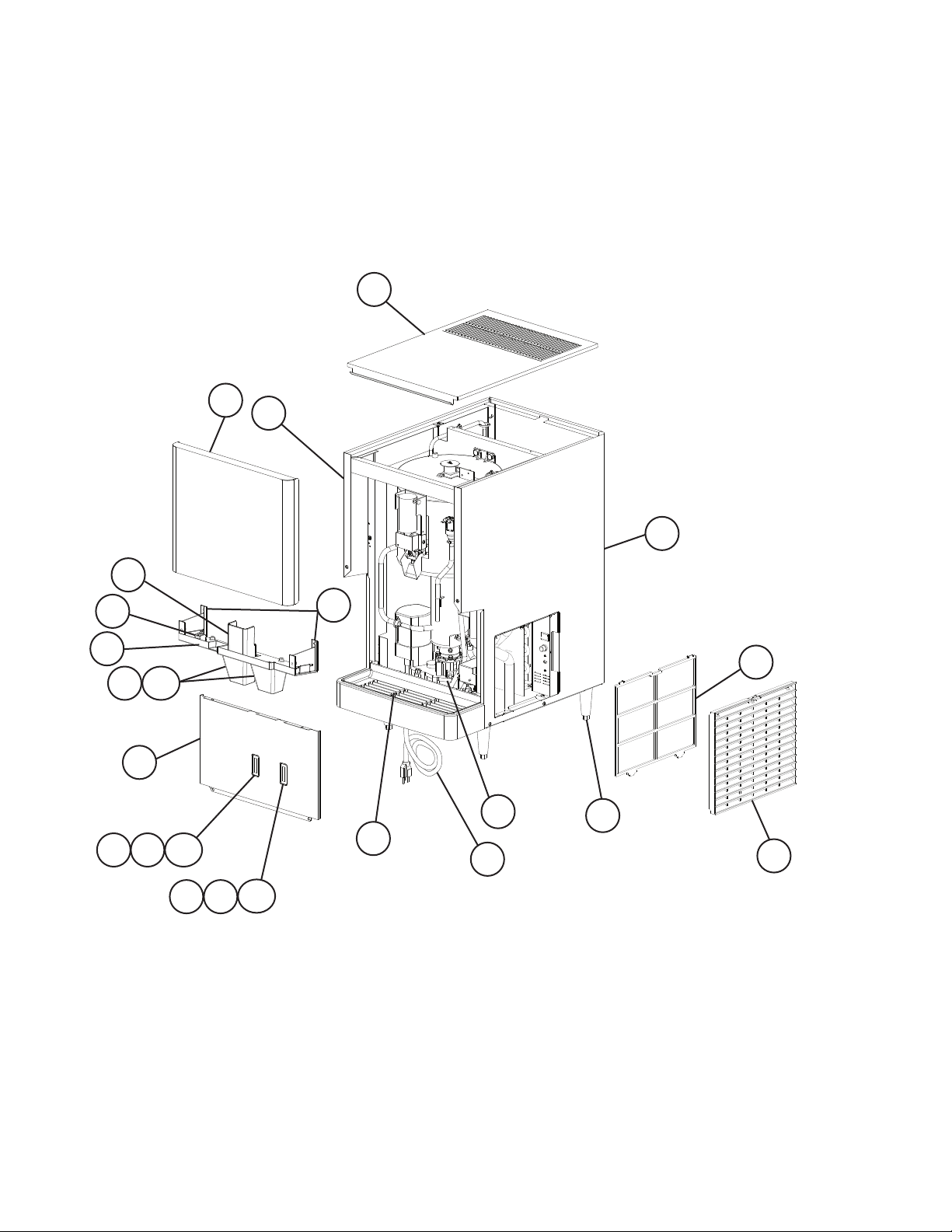
A. Main Assembly
DCM-270BAH-OS
P-1 to F-0
13
4
14
15
12
18
1
19
6
2a
2
8
5
11
11a
10
11
11a
9
3
16
17
7
4
Page 5
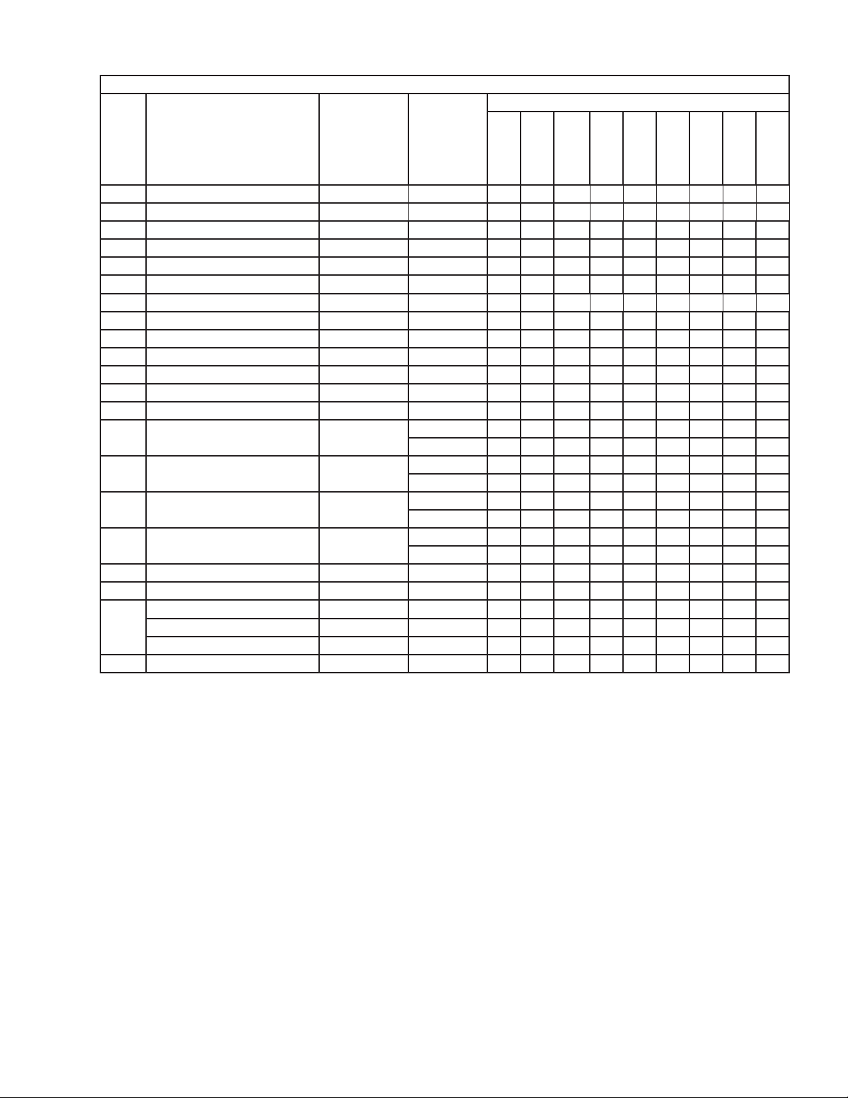
Title: A. Main Assembly Model: DCM-270BAH-OS
Q-0
P-1
(F)
to
S-0
(G)
S-0
(H)
to
U-0
Index
No. Description
1 Spout A 105409-01 1 1 1 1
2 Spout B 105410-01 2 2 2 2
2a Thumbscrew 415949G08 2 2 2 2
3 Grille 102936-04 1 1 1 1
4 Top Panel 2A2916-01 1 1 1 1
5 Gear Motor Drain Pan 3A0766G01 1 1 1 1
6 Air Filter 208840G03 1 1 1 1
7 Louver 103344-07 1 1 1 1
8 Apron Panel 3A3609G01 1 1 1 1
9 Ice Sensor 4A3753G03 1 1 1 1
10 Water Sensor 4A3753G04 1 1 1 1
11 Sensor Latch 4A3848-01 2 2 2
11a Thumbscrew 415949G10 2 2 2
12 Power Switch 421491-08 1 1 1 -
13 Front Panel 3A2902-01 1 1 1 -
14 Left Panel 2A2919-01 1 1 1 -
15 Right Panel 2A2918-01 1 1 1 -
16 Power Cord 4A1773-01 1 1 1 1
17 Adjustable Leg 4A2145-01 4 4 4 4
18 Middle Front Frame - Painted 2A2928G01 1 1 -
Middle Front Frame 2A4263G01 1 Middle Front Frame A 2A5140G02 1
19 Middle Front Frame B 3A5407G01 2
Material or
Model Number Part Number
421490-01 1
2A4714-01 1
2A5189-01 1
2A5190-01 1
to
Q-0
(E)
Required Number
U-1
to
F-0
5
Page 6

B. Refrigeration Circuit
DCM-270BAH-OS
P-1 to F-0
2
B-0 and Later
A-0 and Earlier
1
3
1110
8
9
12
6
5
4
7
6
Page 7

Title: B. Refrigeration Circuit Model: DCM-270BAH-OS
P-1
T-1
Index
No. Description
1 Compressor 4A2272-01 1 -
2 Protector 4A2272F03 1 -
3 Start Relay 4A2294-01 1 1 1
4 Condenser 2A0780-01 1 1 1
5 Fan Motor 4A0815-01 1 1 1
6 Fan Blade 3A0608-01 1 1 1
7 Drier 4A1113-01 1 1 1
8 Thermostatic Expansion Valve 4A1117-01 1 1 1
9 Thermostatic Expansion Valve
Cover
10 Thermostatic Expansion Valve
Bulb Holder
11 Clamp 443461-02 1 1 1
12 High-Pressure Switch 433441-05 1 1 -
Material or
Model Number Part Number
4A4614-01 1 1
4A4614F03 1 1
4A1168-01 1 1 1
3A0107-01 1 1 1
463180-05 1
T- 0
to
to
A-0
Required Number
B-0
to
F-0
7
Page 8

C. Icemaking Unit
DCM-270BAH-OS
1/2
P-1 to D-1
13
21
21a
19
21b
14
15
18
11
17
12
16
8
6
7
22
8a
5
5a
20
"Do not use with item 19 D-2"
10
9
4
3
3a
2
1a
1
8
Page 9

C. Icemaking Unit
DCM-270BAH-OS
2/2
D-2 to F-0
8
6
22
10
9
3a
3
2
16
7
8a
5
5a
4
14
12
17
20
13
11
21a
21
15
18
19
21b
"Do not use with item 20
P-1 to D-1"
1a
1
9
Page 10

Title: C. Icemaking Unit Model: DCM-270BAH-OS
P-1
V-2
Index
No. Description
1 Gear Motor 2U0147-01 1 1 1
1a Socket Head Cap Screw 6×10, SS 7S12-0890 3 3 3
2 Spline Coupling 418316-01 1 1 1
3 Housing 206013G03 1 1 1
3a Hex Bolt 6×20 458660-01 1 1 1
4 O-Ring 7616-G040 1 1 1
5 Evaporator 332576G01 1 1 1
5a Socket Head Cap Screw 6×10, SS 7S12-0610 4 -
6 Auger 361014G01 1 1 1
7 Upper Evaporator
Casing Cover
8 Extruding Head 327236G02 1 1 1
8a Seal Bolt P01768-01 3 3 3
9 Mechanical Seal 432491-01 1 1 1
10 Ring 432494-01 1 1 1
11 Small Balance Plate 465782-01 1 1 1
12 Shaft 465781-01 1 1 1
13 Snap Pin 715S-0004 1 1 1
14 E-Ring 721S-0005 1 1 1
15 Large Balance Plate 417473-02 1 1 1
16 Microswitch 461294-01 1 1 1
17 Agitator 348969G01 1 1 1
18 Drip Ring 207754-03 1 1 1
19 Storage Bin
(Do not use aux. code D-2
and later with item 20 aux.
code P-1 to D-1)
20 Shutter Assembly
(Do not use aux. code P-1 to
D-1 with item 19 aux. code
D-2 and later)
21 Storage Bin Top Cover 240921A01 1 1 1
21a Thumbscrew 430825G01 3 3 3
21b Thumbscrew 415949G08 2 2 2
22 O-Ring 7616-P048 1 1 1
Material or
Model Number Part Number
P01718-01 4 4
413446-01 1 1 471716P01 1
228516G07 1 1 253636G01 1
237274A02 1 1 121220A02 1
to
V-1
to
D-1
Required Number
D-2
to
F-0
10
Page 11

D. Water Circuit
DCM-270BAH-OS
P-1 to F-0
S-0 (F) and Earlier
17
16
12
18
10
15
14
2
16
6
5
7
8
4
9
13
1
3
11
S-0 (G) and Later
17
12
18
16
10
7
14
15
2
16
6
5
8
4
9
13
1
3
11
Page 12

Title: D. Water Circuit Model: DCM-270BAH-OS
Required Number
S-0
P-1
(G)
to
to
Index
No. Description
1 Water Supply Pipe 2A0787G01 1 -
2 Rubber Washer 4A0867-01 2 2 2 2 -
3 Drain Valve 4A2772-01 1 1 1 1 1
4 Reservoir 2A0753-01 1 1 1 1 1
5 Reservoir Cover 214810-01 1 1 1 1 1
6 Reservoir Inlet 4A0869-01 1 1 1 1 1
7 Float Switch 435490-01 1 1 1 1 1
8 Reservoir Separator 4A1255-01 1 1 1 1 1
9 Reservoir Hose 4A1165-03 1 1 1 1 1
10 Tee 4A1140-01 1 1 1 1 1
11 Vinyl Hose L=75 mm 7716-0913 1 1 1 -
12 Vinyl Hose L=215 mm 7725-0912 1 -
13 Vinyl Hose L=280 mm 7725-1923 1 1 1 -
14 Silicone Hose L=35 mm 7730-1114 1 1 1 1 1
15 Silicone Hose L=85 mm 7730I3896 1 1 -
16 Inlet Water Valve/Dispense
Water Valve
17 Drain Pan 318857G04 1 1 1 1 1
18 Water Supply Tube 4A3216G01 1 1 1 1 1
Hose Clamp 4A2017-04 6 6 6 5 5
Hose Clamp 4A2017-05 2 2 2 2 2
Hose Clamp 4A2017-06 1 1 1 1 1
Hose Clamp 4A2017-07 1 1 1 1 1
Material or
Model Number Part Number
2A4181G01 1 1 1 2A4181G02 1
413854-03 2
L=200 mm 1 1 1 1
L=310 mm 7716-2025 1 1
L=90 mm 1 -
L=145 mm 1 1
4A0865-01 2 2 2 2 -
4A5309-01 2
Hose Clamps
S-0
(F)
U-0
(C)
U-0
(D-F)
U-1
to
B-0
B-1
to
F-0
12
Page 13

E. Control Box A
DCM-270BAH-OS
P-1 to F-0
C-0 and Earlier
8
7
2 3
X10 X9
X7
1
8
4 5
10
x7 Gear Motor Protect Relay
(120VAC)
x8 Drain Control Relay (24VAC)
x9 Water Control Relay (24VAC)
x10 Ice Dispense Relay (24VAC)
C-1 and Later
9
11
7
2 3
X8
Compressor Control Relay (120VAC)
Dispense Relay (120VAC)
9
6a
6
1
10
x10 Compressor Control Relay
(120VAC)
x11 Dispense Relay (120VAC)
13
6a
6
Page 14

Title: E. Control Box A Model: DCM-270BAH-OS
Required Number
P-1
U-0
to
(D)
A-0
B-2
Index
No. Description
1 Control Transformer 2U0042-02 1 1 1 -
2 Fuse Holder 4A0892-01 1 1 -
3 Fuse AGC-1A,
4 Fuse Holder 4A0892-02 1 1 -
5 Fuse AGC-500mA,
6 Control Board Timer Board
6a Control Board Support 4A0336-03 4 4 4 4 4
7 Control Switch 4A1034-01 1 1 1 1 1
8 Relay (X8, X9, X10) 24VAC 406132-03 3 3 3 3 9 Relay (X7 P-1 to C-0)
(X10 C-1 and later)
10 Gear Motor External Protector GMD-1.6A,
11 Dispense Relay (X11) 120VAC 406132-07 1
Material or
Model Number Part Number
3A6652-01 1 4A0557-01 1
4A3449-01 1 1 4A5443-01 1
4A0893-01 1 1 1 1 1
250VAC
4A3449-02 1 4A5443-01 1 4A0893-02 1 1 1 1 -
250VAC
2A2867-01 1 1 1 1 -
-OS
"F-A" Control
Board
120VAC 418271-03 1 1 1 1 1
120VAC
Slow Blow
2A4296-01 1
427253-01 1 1 1 1 1
U-0
(C)
to
V-4
to
B-1
to
C-0
C-1
to
F-0
14
Page 15

F. Control Box B
DCM-270BAH-OS
P-1 to F-0
2
1
Title: F. Control Box B Model: DCM-270BAH-OS
Index
No. Description
1 Start Capacitor 145-174MFD,
2 Gear Motor Capacitor 10MFD,
Material or
Model Number Part Number
250VAC
280VAC
Required Number
P-1
to
F-0
3A0076-01 1
416921-05 1
15
Page 16

G. Accessories & Labels
DCM-270BAH-OS
P-1 to F-0
1
Title: G. Accessories & Labels Model: DCM-270BAH-OS
Index
No. Description
1 Penguin Label 456246-01 1
2 Ice/Water Label 4A2954-01 1
Material or
Model Number Part Number
16
2
Required Number
P-1
to
F-0
 Loading...