

Hoshizaki CR1S-FSL, CF1S-HSL Service Manual
Service Manual
Commercial Series
Refrigerated Kitchen Equipment
Models
Upright S-Series
hoshizakiamerica.com
Number: 73207
Issued: 8-3-2015
Revised: 6-24-2016
WARNING
Only qualied service technicians should install and service the appliance. To
obtain the name and phone number of your local Hoshizaki Certied Service
Representative, visit www.hoshizaki.com. No service should be undertaken until
the technician has thoroughly read this Service Manual. Failure to service and
maintain the appliance in accordance with this manual will adversely affect safety,
performance, component life, and warranty coverage. Proper installation is the
responsibility of the installer. Product failure or property damage due to improper
installation is not covered under warranty.
Hoshizaki provides this manual primarily to assist qualied service technicians in the
service and maintenance of the appliance.
Should the reader have any questions or concerns which have not been satisfactorily
addressed, please call, send an e-mail message, or write to the Hoshizaki Technical
Support Department for assistance.
Phone: 1-800-233-1940; (770) 487-2331
Fax: 1-800-843-1056; (770) 487-3360
E-mail: techsupport@hoshizaki.com
HOSHIZAKI AMERICA, INC.
618 Highway 74 South
Peachtree City, GA 30269
Attn: Hoshizaki Technical Support Department
Web Site: www.hoshizaki.com
NOTE: To expedite assistance, all correspondence/communication MUST include the
following information:
• Model Number
• Serial Number
• Complete and detailed explanation of the problem.
2

IMPORTANT
This manual should be read carefully before the appliance is serviced. Read
the warnings and guidelines contained in this manual carefully as they provide
essential information for the continued safe use, service, and maintenance of the
appliance. Retain this manual for any further reference that may be necessary.
CONTENTS
Important Safety Information ................................................................................................. 5
I. General Information ............................................................................................................ 8
A. Construction .................................................................................................................. 8
B. Refrigeration Flow Chart ............................................................................................. 10
II. Sequence of Operation and Service Diagnosis ................................................................11
A. Sequence of Operation Flow Charts ............................................................................ 11
1a. Refrigerator Auxiliary Code F-6 and Earlier ..........................................................11
1b. Refrigerator: Auxiliary Code F-7 and Later ........................................................... 12
2a. Freezer: Auxiliary Code F-7 and Earlier ............................................................... 13
2b. Freezer: Auxiliary Code F-8 and Later ................................................................. 14
B. Service Diagnosis ....................................................................................................... 15
1a. Refrigerator: Auxiliary Code F-6 and Earlier ........................................................ 16
1b. Refrigerator: Auxiliary Code F-7 and Later ........................................................... 19
2a. Freezer: Auxiliary Code F-7 and Earlier ............................................................... 22
2b. Freezer: Auxiliary Code F-8 and Later ................................................................. 27
C. Control Module Check ................................................................................................. 32
D. Thermistor Check ........................................................................................................ 34
E. Diagnostic Tables ........................................................................................................ 35
III. Controls and Adjustments ............................................................................................... 37
A. Control Module ............................................................................................................ 37
1. Display Icons ...................................................................................................... 37
2. Display Layout .................................................................................................... 37
3. Control Module Connections ............................................................................... 38
B. Temperature ............................................................................................................... 39
1. Default Settings ...................................................................................................... 39
2. Temperature Setpoint ............................................................................................ 39
3. Changing the Temperature Display Scale (°F or °C) ............................................. 39
C. Defrost ........................................................................................................................ 40
D. Alarm Safeties ............................................................................................................. 41
E. Safety Devices ............................................................................................................ 42
F. Mullion/Perimeter Heater ............................................................................................. 42
IV. Replacement of Components ......................................................................................... 43
A. Service for Refrigerant Lines ....................................................................................... 43
B. Important Notes for Component Replacement ............................................................ 46
C. Door Reversal ............................................................................................................. 46
V. Maintenance .................................................................................................................... 47
VI. Preparing the Appliance for Periods of Non-Use ............................................................ 48
VII. Disposal ......................................................................................................................... 49
3

VIII. Technical Information .................................................................................................... 50
A. Electrical and Refrigerant Data ................................................................................... 50
B. Wiring Diagrams .......................................................................................................... 51
1. CR1S-FS/FSL/HS/HSL Auxiliary Code E-5 and Earlier ......................................... 51
2. CR2S-FS/HS Auxiliary Code E-5 and Earlier ........................................................ 52
3. CR1S-FGY/FS/FSL/HS/HSL,
CR2S-FGY/FS/HS/FGY,
CR3S-FS/HS Auxiliary Code E-6 to F-6 ................................................................ 53
4. CR1S-FGE/FGECL/FGECR/FS/FSL/HS/HSL,
CR2S-FGE/FS/HS Auxiliary Code F-7 and Later .................................................. 54
5. CF1S-FS/FSL/HS/HSL Auxiliary Code E-5 and Earlier ......................................... 55
6. CF1S-FS/FSL/HS/HSL Auxiliary Code E-6 to F-7 ................................................. 56
7. CF1S-FGE/FGECL/FGECR/FS/HS F-8 and Later ................................................. 57
8. CF2S-FS/HS Auxiliary Code E-5 and Earlier ......................................................... 58
9. CF2S-FS/FSL/HS/HSL Auxiliary Code E-6 to F-7 ................................................. 59
10. CF2S-FGE/FGECL/FGECR/FS/FSL/HS/HSL Auxiliary Code F-8 and Later ....... 60
11. CR3S-FS/HS Receptacle Box Connection ........................................................... 61
4
Important Safety Information
Throughout this manual, notices appear to bring your attention to situations which could
result in death, serious injury, or damage to the appliance or damage to property.
WARNING Indicates a hazardous situation which could result in death or
serious injury.
NOTICE Indicates a situation which could result in damage to the
appliance or property.
IMPORTANT Indicates important information about the use and care of the
appliance.
WARNING
The appliance should be destined only to the use for which it has been expressly
conceived. Any other use should be considered improper and therefore dangerous.
The manufacturer cannot be held responsible for injury or damage resulting from
improper, incorrect, and unreasonable use. Failure to service and maintain the
appliance in accordance with this manual will adversely affect safety, performance,
component life, and warranty coverage.
To reduce the risk of death, electric shock, serious injury, or re, follow basic
precautions including the following:
• Only qualied service technicians should install and service the appliance.
• The appliance must be installed in accordance with applicable national, state, and
local codes and regulations.
• The appliance requires an independent power supply of proper capacity. Seethe
nameplate for electrical specications. Failure to use an independent power
supply of proper capacity can result in a tripped breaker, blown fuse, or damage
to existing wiring. This could lead to heat generation or re.
• To reduce the risk of electric shock, do not touch the plug or power switch with
damp hands.
• Make sure the power switch is in the "OFF" position before plugging in or
unplugging the appliance to reduce the risk of electric shock.
• Before servicing, move the power switch to the "OFF" position. Unplug the
appliance from the electrical outlet.
For 115VAC Models
• THE APPLIANCE MUST BE GROUNDED: The appliance is equipped with a
NEMA5-15 three-prong grounding plug
hazards. It must be plugged into a properly grounded, independent 3-prong wall
outlet. If the outlet is a 2-prong outlet, it is your personal responsibility to have a
qualied electrician replace it with a properly grounded, independent 3-prong wall
outlet. Do not remove the ground prong from the plug and do not use an adapter
plug. Failure to follow these instructions may result in death, electric shock, or re.
to reduce the risk of potential shock
5
WARNING, continued
For 208-230VAC Models
• THE APPLIANCE MUST BE GROUNDED: The appliance is equipped with a
NEMA L14-20 four-prong locking, grounding plug
shock hazards. It must be plugged into a properly grounded, independent 4-prong
wall outlet. If the outlet is a 3-prong outlet or a 4-prong non-locking outlet, it is your
personal responsibility to have a qualied electrician replace it with a properly
grounded, independent 4-prong locking wall outlet. Do not remove the ground
prong from the plug and do not use an adapter plug. After plugging in, twist the plug
clockwise to lock it into place. Failure to follow these instructions may result in death,
electric shock, or re.
For All Models
• The GREEN ground wire in the factory-installed power cord is connected to the
appliance. If it becomes necessary to remove or replace the power cord, be sure to
connect the power cord's ground wire.
• Do not use an extension cord.
• Do not use an appliance with a damaged power cord. The power cord should not
be altered, jerked, bundled, weighed down, pinched, or tangled. Such actions could
result in electric shock or re. To unplug the appliance, be sure to pull the plug, not
the cord, and do not jerk the cord. Before unplugging a 4-prong plug, rotate the plug
counter-clockwise to unlock it.
to reduce the risk of potential
• Do not splash, pour, or spray water directly onto or into the appliance. This might
cause short circuit, electric shock, corrosion, or failure.
• Do not make any alterations to the appliance. Alterations could result in electric
shock, injury, re, or damage to the appliance.
• The appliance is not intended for use by persons (including children) with reduced
physical, sensory, or mental capabilities, or lack of experience and knowledge,
unless they have been given supervision or instruction concerning use of the
appliance by a person responsible for their safety.
• Children should be properly supervised around the appliance.
• Do not climb, stand, or hang on the appliance or door or allow children or animals to
do so. Do not climb into the appliance or allow children or animals to do so. Death or
serious injury could occur or the appliance could be damaged.
• Be careful not to pinch ngers when opening and closing the door. Be careful when
opening and closing the door when children are in the area.
• Open and close the doors with care. Doors opened too quickly or forcefully may
cause injury or damage to the appliance or surrounding equipment.
• Do not use combustible spray or place volatile or ammable substances near the
appliance. They might catch re.
• Keep the area around the appliance clean. Dirt, dust, or insects in the appliance
could cause harm to individuals or damage to the appliance.
• Do not throw anything onto the shelves or load any single shelf with more than
120lb. (54.5 kg) of product. They might fall off and cause injury.
6
WARNING, continued
• Do not place anything on top of the appliance. Foreign objects or moisture could
enter the appliance and result in electric shock or re.
• The appliance is designed only for temporary storage of food. Employ sanitary
methods. Use for any other purposes (for example, storage of chemicals or medical
supplies such as vaccine and serum) could cause deterioration of stored items.
• Do not block air inlets or outlets, otherwise cooling performance may be reduced.
• Do not tightly pack the cabinet. Allow some space between items to ensure good air
ow. Also allow space between items and interior surfaces.
• Do not put warm or hot foods in the cabinet. Let them cool rst, or they will raise the
cabinet temperature and could deteriorate other foods in the cabinet or overload the
appliance.
• All foods should be wrapped in plastic lm or stored in sealed containers. Otherwise
foods may dry up, pass their smells onto other foods, cause frost to develop, result
in poor appliance performance, or increase the likelihood of cross-contamination.
Certain dressings and food ingredients, if not stored in sealed containers, may
accelerate corrosion of the evaporator, resulting in failure.
• Do not store items near the air outlet. They might freeze up and crack or break
causing a risk of injury or contamination of other food.
NOTICE
• Protect the oor when moving the appliance to prevent damage to the oor.
• Keep ventilation openings, in the appliance enclosure or in the built-in structure,
clear of obstruction. Do not place anything on top of the appliance. Blockage of
airow could negatively affect performance and damage the appliance.
• To prevent deformation or cracks, do not spray insecticide onto the plastic parts or
let them come into contact with oil.
• To avoid damage to the gasket, use only the door handle when opening and closing.
7
I. General Information
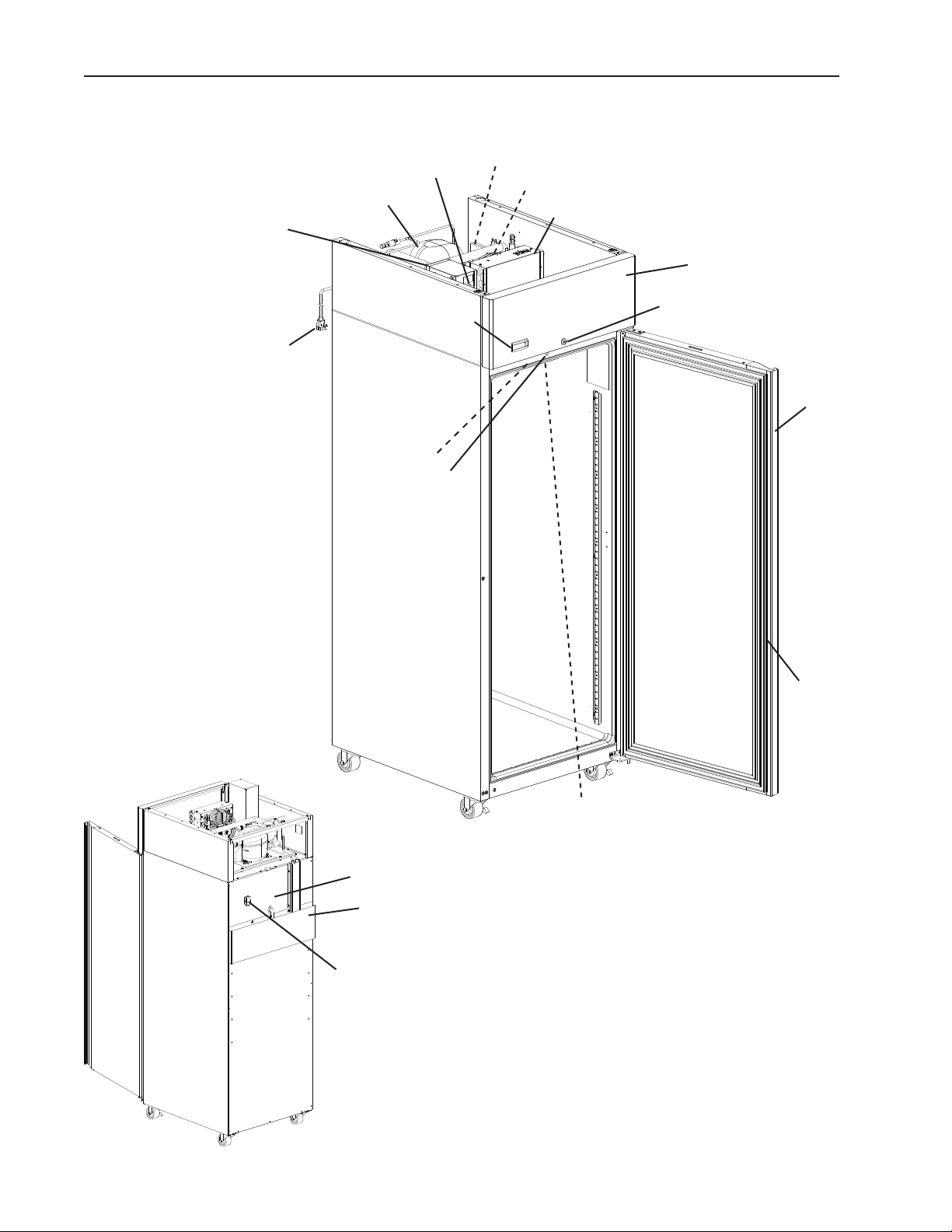
A. Construction
1. Solid Door Models
Control Box
Power Switch
Compressor
Thermostatic Expansion Valve
Condenser Fan Motor
Condenser
Front Panel
Power Cord
Control Module
Light
Door Switch
Door Lock
Door
Door
Gasket
Condensate Tube and Spring
Condensate Pan
Pressure Relief Valve
Model Shown: CR1S-FS
8
• Evaporator
• Cabinet Thermistor
• Defrost Thermistor
• Evaporator Fan Shroud
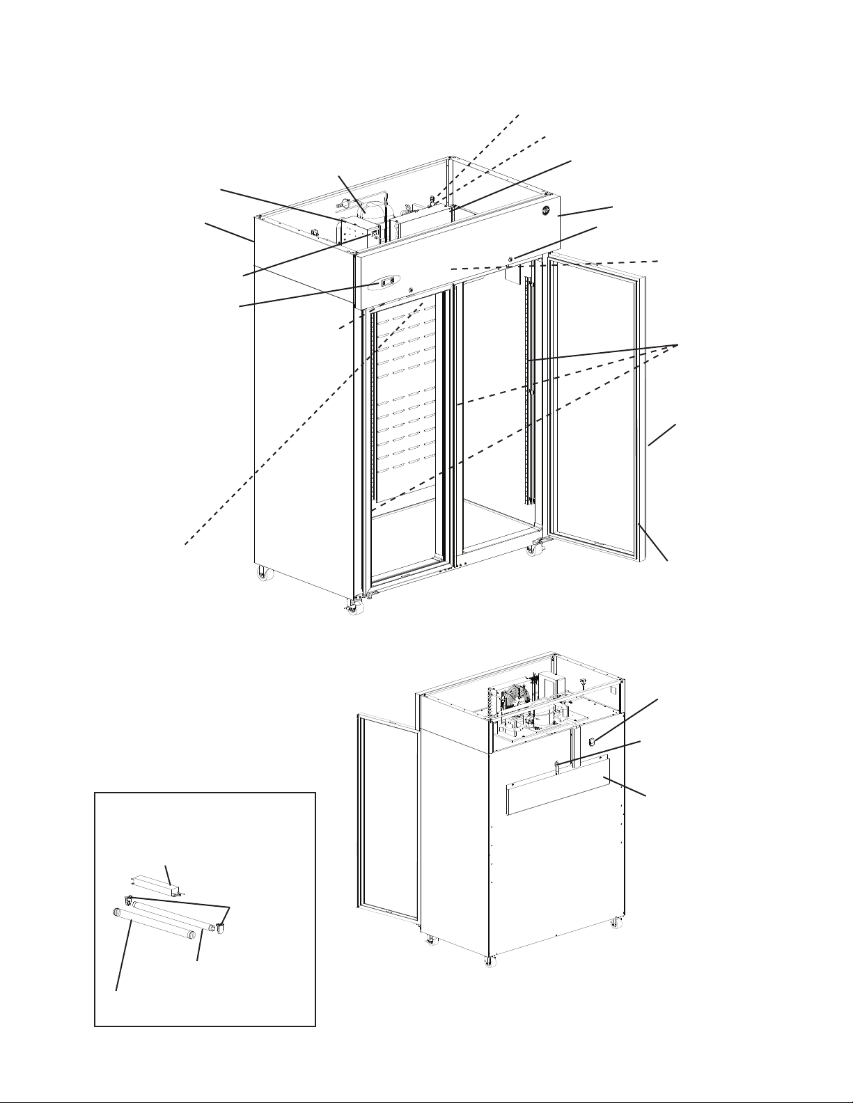
2. Glass Door Models
Thermostatic Expansion Valve
Condenser Fan Motor
Control Box
Power Cord
Power Switch
Control Module
• Evaporator
• Cabinet Thermistor
• Defrost Thermistor
• Evaporator Fan Shroud
Compressor
Light Switch
(glass door
models only)
Condenser
Front Panel
Door Lock
24VDC Driver
FGE Glass
Door Models
LED Lights
FGE Glass
Door Models
Door
Door
Gasket
Fluorescent Light Assembly:
FGY Glass Door Models
Fluorescent Light Ballast
Fluorescent
Light Mount
Fluorescent Light
Bulb
Fluorescent Light
Bulb Guard
Model Shown: CR2S-FGE
Pressure Relief
Valve
Condensate Tube
and Spring
Condensate Pan
Model Shown: CR2S-FGE
9
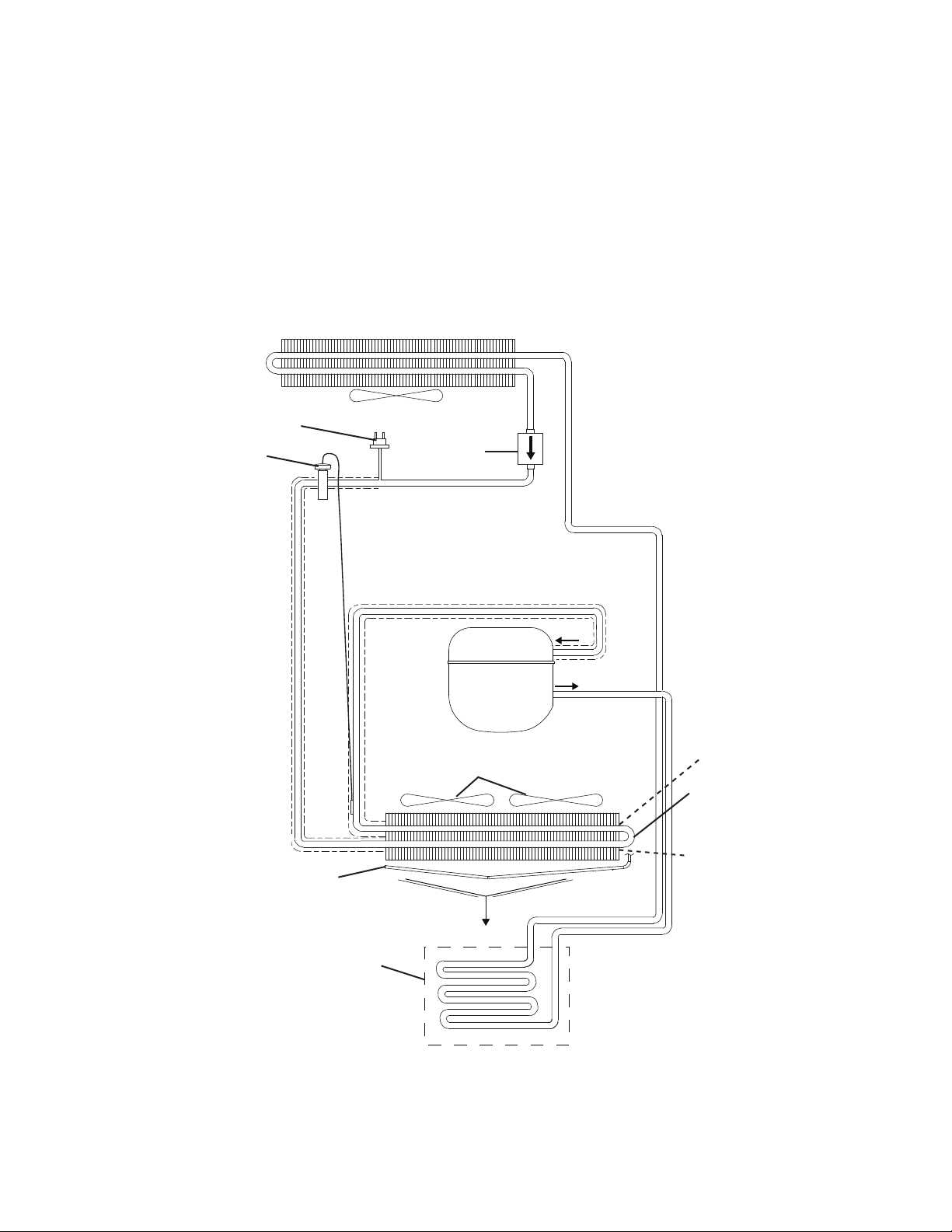
B. Refrigeration Flow Chart
Condenser
High-Pressure Switch
Thermostatic
Expansion Valve
Defrost Heater and
Defrost Thermostat
(freezer only)
Condenser Fan
Evaporator Fans
(quantity depends on model)
Drier
Compressor
Defrost
Thermistor
Evaporator
Cabinet Thermistor
Condensate Pan
10
II. Sequence of Operation and Service Diagnosis
A. Sequence of Operation Flow Charts
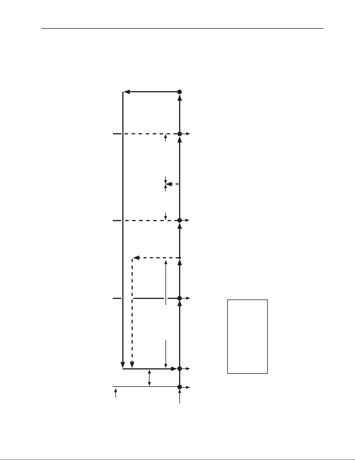
1a. Refrigerator Auxiliary Code F-6 and Earlier
DTh warms to
40°F (4.4°C) or
1-hr maximum
defrost timer
5. Defrost Termination
terminates
Comp energized
ConFM energized
EvapFM energized
DTh in control
20-min.
minimum
2-hr defrost timer
4. Defrost
2. Cool Down Achieved
terminates
CTh warms
to 3°F (1.7°C)
above
CTh cools
to 3°F (1.7°C)
below setpoint.
setpoint
Factory default
3. Cool Down Restart
Refrigerator Auxiliary Code F-6 and Earlier Sequence Flow Chart
defrost
36°F (2°C)
2-min. Comp off
timer starts
CTh in control
2-min. Comp on
timer starts
EvapFM energized
EvapFM energized
Comp energized
Comp de-energized
Comp de-energized
ConFM energized
ConFM de-energized
ConFM de-energized
EvapFM energized
Note:
Legend:
a) EvapFM de-energizes when door is opened on -FS models and
Comp-compressor
when upper door is opened on -HS models.
b) 2-min. minimum Comp on timer starts when Comp energizes.
c) 2-min. minimum Comp off timer starts when Comp de-energizes.
d) 20-min. minimum defrost time.
e) 1-hr. maximum defrost time.
f) Temperature displayed during defrost.
ConFM-condenser fan motor
CTh-cabinet thermistor
DTh-defrost thermistor
EvapFM-evaporator fan motor
1. Startup/Cool Down
Cycle Steps
Slight
Delay at
Startup
EvapFM energized
Power On
11
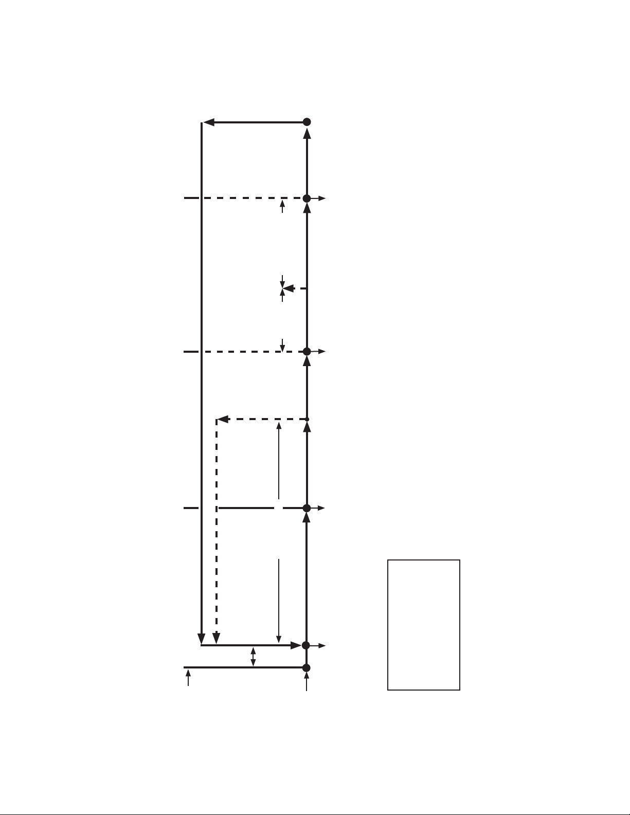
1b. Refrigerator: Auxiliary Code F-7 and Later
DTh warms to
44°F (6.6°C) or
1-hr maximum
defrost timer
terminates
terminates
DTh in control
20-min.
minimum
defrost
5. Defrost Termination
2-hr defrost timer
4. Defrost
Comp energized
ConFM energized
EvapFM energized
Comp de-energized
ConFM de-energized
EvapFM de-energized
CTh warms
to 3°F (1.7°C)
above setpoint
CTh cools to
3°F (1.7°C)
below setpoint.
Factory default
33°F (1°C)
2-min. Comp off
2. Cool Down Achieved
Refrigerator Auxiliary Code F-7 and Later Sequence Flow Chart
timer starts
a) EvapFM de-energizes when door is opened on -FS models and when upper door is opened on -HS models.
b) 2-min. minimum Comp on timer starts when Comp energizes.
c) 2-min. minimum Comp off timer starts when Comp de-energizes.
d) 20-min. minimum defrost time.
e) 1-hr. maximum defrost time.
Comp de-energized
ConFM de-energized
EvapFM de-energized
CTh in control
Note:
f) Temperature displayed during defrost.
3. Cool Down Restart
2-min. Comp on
timer starts
Comp energized
ConFM energized
EvapFM energized
1. Startup/Cool Down
Legend:
Comp-compressor
ConFM-condenser fan motor
CTh-cabinet thermistor
DTh-defrost thermistor
EvapFM-evaporator fan motor
Cycle Steps
Slight
Delay at
Startup
Power on
12

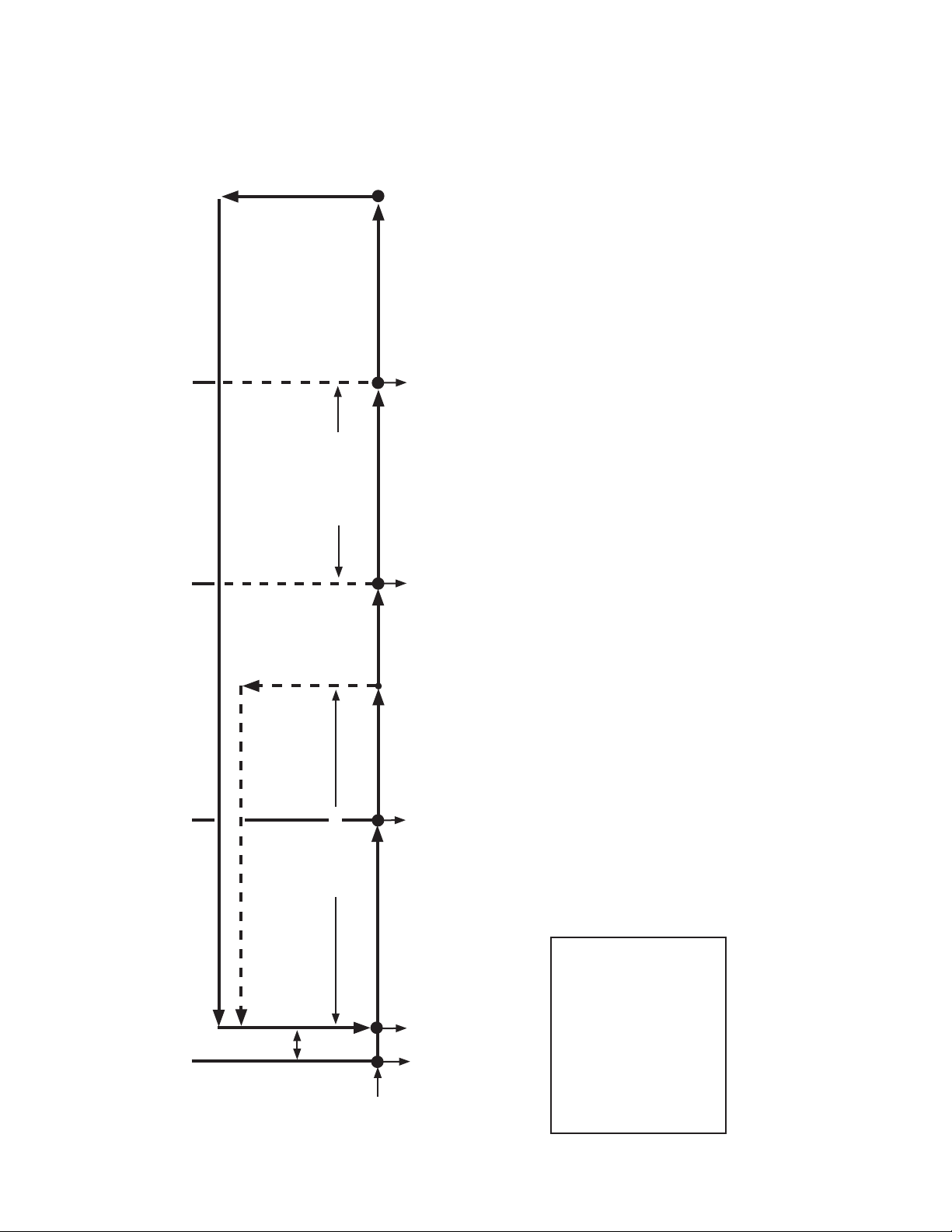
2a. Freezer: Auxiliary Code F-7 and Earlier
DTh warms to 59°F (15°C)
5. Defrost Termination
MH energized
DTh in control
PH energized
DH de-energized
DrH de-energized
After Delay:
Comp energized
ConFM energized
EvapFM energized
4-hr cumulative Comp run
4. Defrost
2. Cool Down Achieved
Freezer Auxiliary Code F-7 and Earlier Sequence Flow Chart
time defrost timer terminates
DH energized
DrH energized
MH energized
PH energized
Comp de-energized
ConFM de-energized
EvapFM de-energized
CTh warms
to 3°F (1.7°C)
above setpoint
CTh cools to
3°F (1.7°C)
below setpoint.
Factory default
-4°F (-20°C)
2-min. Comp off
timer starts
EvapFM energized
MH energized
PH energized
Comp de-energized
ConFM de-energized
a) EvapFM de-energizes when door is opened on -FS models and when upper door is opened on -HS models.
b) 2-min. minimum Comp on timer starts when Comp energizes.
c) 2-min. minimum Comp off timer starts when Comp de-energizes.
d) 5-min. minimum defrost time.
e) 1-hr. maximum defrost time.
f) 3-min. Comp/ConFM delay timer starts when defrost termination temperature is met.
g) 7-minute EvapFM delay timer starts when defrost termination temperature is met (3-minute delay timer when defrost initiated manually)
h) 18-minute temperature display delay timer starts when defrost termination temperature is met (15-minute delay timer when defrost
Note:
CTh in control
initiated manually).
3. Cool Down Restart
2-min. Comp on
4-hr. cumulative Comp run
time defrost timer starts
timer starts
Comp energized
ConFM energized
EvapFM energized
MH energized
PH energized
1. Startup/Cool Down
Slight
Delay at
Startup
Power on
MH energized
13
PH energized
Legend:
Comp-compressor
ConFM-condenser fan motor
CTh-cabinet thermistor
DH-defrost heater
DrH-drain heater
DTh-defrost thermistor
EvapFM-evaporator fan motor
MH-mullion heater
PH-perimeter heater
2b. Freezer: Auxiliary Code F-8 and Later
DTh warms to 45°F (7.2°C)
5. Defrost Termination
DH de-energized
DTh in control
DrH energized
After Delay:
Comp energized
ConFM energized
EvapFM energized
MH energized
PH energized
5-hr. cumulative Comp run
4. Defrost
2. Cool Down Achieved
time defrost timer terminates
CTh cools to
CTh warms
to 3°F (1.7°C)
3°F (1.7°C)
below setpoint.
above setpoint
Factory default
-4°F (-20°C)
2-min. Comp off
CTh in control
DH energized
DrH energized
Comp de-energized
ConFM de-energized
EvapFM de-energized
MH de-energized
PH de-energized
timer starts
Comp de-energized
ConFM de-energized
DrH energized
EvapFM de-energized
MH de-energized
PH de-energized
a) EvapFM de-energizes when door is opened on -FS models and when upper door is opened on -HS models.
b) 2-min. minimum Comp on timer starts when Comp energizes.
c) 2-min. minimum Comp off timer starts when Comp de-energizes.
d) 5-min. minimum defrost time.
e) 1-hr. maximum defrost time.
f) 3-min. Comp/ConFM/MH/PH delay timer starts when defrost termination temperature is met.
g) 7-minute EvapFM delay timer starts when defrost termination temperature is met (3-minute delay timer when defrost initiated manually)
h) 18-minute temperature display delay timer starts when defrost termination temperature is met (15-minute delay timer when defrost
Note:
initiated manually).
Freezer Auxiliary Code F-8 and Later Sequence Flow Chart
3. Cool Down Restart
2-min. Comp on
timer starts
Comp energized
ConFM energized
DrH energized
EvapFM energized
MH energized
PH energized
1. Startup/Cool Down
5-hr. cumulative Comp run
time defrost timer starts
Slight
Delay at
Startup
Power on
DrH energized
14
Legend:
Comp-compressor
ConFM-condenser fan motor
CTh-cabinet thermistor
DH-defrost heater
DrH-drain heater
DTh-defrost thermistor
EvapFM-evaporator fan motor
MH-mullion heater
PH-perimeter heater
B. Service Diagnosis
WARNING
• The appliance should be diagnosed and repaired only by qualied service
personnel to reduce the risk of death, electric shock, serious injury, or re.
• Risk of electric shock. Use extreme caution and exercise safe electrical practices.
• Moving parts (e.g., fan blade) can crush and cut. Keep hands clear.
• Make sure all food zones are clean after the appliance is serviced.
NOTICE
• This appliance is not intended for outdoor use.
• Normal operating ambient temperature:
– Refrigerators and Solid Door Freezers 45°F to 100°F (7.2°C to 38°C)
– Glass Door Freezers 45°F to 80°F (7.2°C to 27°C)
Operation of the appliance, for extended periods, outside of this normal
temperature range may affect appliance performance.
• The appliance must not be located next to ovens, grills, or other high heat
producing equipment.
• The appliance must not be located in a corrosive environment.
• Minimum Clearance:
Side Top Rear
3" (8 cm) 12" (31 cm) 1" (3 cm)
The diagnostic procedure is a sequence check that allows you to diagnose the electrical
system and components. Before proceeding, check for correct installation and proper
voltage per nameplate. Always choose a neutral (W) to establish a good neutral
connection when checking high voltages. If the display is in alarm, see "III.D. Alarm
Safeties."
IMPORTANT
The maximum allowable voltage variation is ±10 percent of the nameplate rating.
115VAC is used as a reference voltage when checking voltage to components.
Voltage may vary depending on power supply.
1. Factory Default Settings:
a) Temperature Setpoint:
Model Auxiliary Code Temperature Setpoint
Refrigerator F-6 and Earlier 36°F (2°C)
F-7 and Later 33°F (1°C)
Freezer All -4°F (-20°C)
b) Temperature Display Scale: °F.
For further details, see "II.C. Control Module Check" or "III. Controls and Adjustments."
• There is a minimum 2-min. Comp on time and 2-min. Comp off time.
15

1) Move the power switch to the "OFF" position.
2) Unplug the appliance from the electrical outlet.
3) Remove the control box cover.
4) Plug the appliance back into the electrical outlet.
5) Move the power switch to the "ON" position.
6) Conrm 115VAC at the power switch. On 3-section models, also conrm proper supply
voltage at the receptacle box (115VAC for refrigerator/208-230VAC for freezer).
1a. Refrigerator: Auxiliary Code F-6 and Earlier
7) Startup/Cool Down–There is a slight delay, cabinet temperature appears on display.
Comp, ConFM, EvapFM, and MH energize. 2-hr defrost timer starts.
a) EvapFMDiagnosis: Conrm EvapFM energizes. If not, conrm doors are closed
and DS engaged. Next, check for 115VAC at DSR #8 (LBU or GY) to DSR #7(W).
If115VAC is not present, check DS continuity. If DS is engaged and contacts are
open, replace DS. If 115VAC is present, check for 115VAC at DSR #4(DBU) to
neutral (W). If115VAC is not present, check for 115VAC at DSR #6(BK or W/BU) to
neutral(W). If 115VAC is present at DSR #6 (BK or W/BU) to neutral (W) and not at
DSR#4(DBU) to neutral (W), replace DSR. If 115VAC is present at DSR #4 (DBU) to
neutral (W), check EvapFM blades for binding and EvapFM continuity.
b) Cabinet Light FGY (FGYCR and FGYCL) Diagnosis: Open the door and conrm
CLS is in the ON position. If not, move CLS to the ON position. CLS turns on. If
CLS does not turn on, check for 115VAC at both CLS (BK) wires to neutral(W). If
115VAC is present at 1 CLS(BK) wire and not at the other, conrm power supply
and continuity of CLS switch. If power supply is ok, check CLS continuity. IfCLS
is engaged and CLS switch is open, replace CLS. If CLS is engaged, contacts are
closed, and 115VAC is present at CLS(BK) and CL is not energized, replace CL.
FS/HS CL Diagnosis: Open the door (upper on HS) and conrm CL is energized.
Ifnot, with the door open, check for 115VAC at DSR #5 (BK) to neutral(W) and DSR
#1 (V or Y) to neutral(W). If115VAC is not present at DSR #5 (BK), conrm power
supply and continuity of power switch. If 115VAC is present at DSR #5 (BK) and not
present at DSR #1 (V or Y), check DS continuity. IfDS is disengaged and contacts
are closed (DSR energized), replace DS. If DSR is de-energized and 115VAC is
present at DSR#5(BK) and not at DSR #1 (V or Y) to neutral (W), replace DSR.
If 115VAC is present at DSR #1 (V or Y) and CL is not energized, replace CL.
c) CM Diagnosis: Cabinet temperature appears on display. If not, check for 115VACat
CM L2 (BK) to CM N3 neutral (W). If 115VAC is not present, check power switch,
power cord connections, and breaker/fuse. Conrm wiring connections are secure for
both CM L2 (BK) (power supply) and CMN3(W) (neutral). If 115VAC is present and
display is off, replace CM.
16

d) Comp and ConFM Diagnosis: Conrm Comp and ConFM energize. Ifnot, check for
115VAC at CM C1 (R or V) to neutral(W). If 115VAC is not present, check CTh status.
See "II.D.Thermistor Check." IfCTh ohm reading is in proper range, replace CM.
If115VAC is present at CM C1 (R or V) to neutral (W), check for 115VAC at CR #0
(GY or P) to CR#1(W). If 115VAC is not present, check continuity of HPS. If open,
allow time for HPS to reset (cut out: 300±10 PSIG, cut in: 190±20 PSIG). If HPS does
not reset, see "e) HPS Activation" below. IfHPS is closed and 115VAC is present,
check for 115VAC at CR#4(BK) and CR #6(R) to neutral (W). If 115VAC is present
at CR #4 (BK) and not at CR#6(R), replace CR. If115VAC is present at CR #6 (R)
to neutral (W) and ConFM is energized but Comp is not, give time for Comp internal
protector to cool and reset. Next, check Comp start capacitor, start relay, and Comp
motor windings. If Comp does not start, replace Comp. If ConFM is not energized,
check ConFM fan blades for binding and motor winding continuity.
If Comp and ConFM are energized and the cabinet does not cool down, check for a
restriction in the refrigeration circuit, correct TXV operation, and correct refrigerant
charge.
e) HPS Activation (cut out: 300±10 PSIG, cut in: 190±20 PSIG): Conrm ConFM
is energized and fan blade turns freely. Conrmcondenser coil is not clogged or
restricted. Conrm there are no restrictions in the refrigeration circuit (TXV and drier).
Let refrigeration circuit pressures equalize. IfHPS does not reset and pressures
are equalized, replace HPS. Ifpressures are not equalized, reclaim refrigerant and
diagnose refrigeration circuit restriction.
8) Cool Down Achieved–CTh cools to 3°F (1.7°C) below setpoint. EvapFM continues.
Comp and ConFM de-energize. Diagnosis: Conrm Comp and ConFM de-energize.
If not, and Comp and ConFM were energized longer than 2 min., check CTh status.
See "II.D. Thermistor Check." If CTh ohm reading is in range and Comp and ConFM
continue longer than 2 min., check for 115VAC at CM C1 (R or V) to neutral(W).
If115VAC is present, replace CM. If 115VAC is not present and Comp and ConFM
continue, check for 115VAC at CR #1 (R or V). If 115VAC is present, replace CR.
9) Defrost–Cabinet temperature is displayed during defrost. There is a 20-min. minimum
defrost time, a 1-hr. maximum defrost time, and a 2-hr. minimum defrost interval.
1a) Time-Initiated: 2-hr. defrost timer terminates. EvapFM continues. Comp and ConFM
de-energize.
1b) Manually-Initiated: To initiate a manual defrost, press the manual defrost button
on display. Defrost icon turns on and, if energized, Comp and ConFM de-energize.
Cabinet temperature is displayed during defrost.
2) Defrost Termination: DTh warms to 40°F (4.4°C). EvapFM and MH continue. Comp
and ConFM energize.
17

Defrost Diagnosis:
1a) Time-Initiation: 2-hr. defrost timer terminates.
(1) CM Diagnosis: Conrm defrost icon turns on, "dEF" is displayed, and Comp
icon turns off. If not, replaceCM.
(2) Comp and ConFM Diagnosis: Conrm Comp and ConFM de-energize.
If not, check for 115VAC at CM C1 (R or V) to neutral (W). If 115VAC is present,
replace CM. If 115VAC is not present and Comp and ConFM continue, check
CR#6(R) to neutral (W). If 115VAC is present, replace CR.
1b) Manual-Initiation: After pressing the manual defrost button, check the following:
(1) CM Diagnosis: Conrm Comp icon turns off, defrost icon turns on, and "dEF" is
displayed. If not, replace CM.
(2) Comp and ConFM Diagnosis: Conrm Comp and ConFM de-energize.
If not, check for 115VAC at CM C1 (R or V) to neutral (W). If 115VAC is present,
replace CM. If 115VAC is not present and Comp and ConFM continue, check
CR#6(R) to neutral (W). If 115VAC is present, replace CR.
2) Defrost Temperature Termination: DTh warms to 40°F (4.4°C). If not, conrm
DTh status. See "II.D. Thermistor Check." If DTh is in proper range, have Comp and
ConFM energized? If not, see "7d) Comp and ConFM Diagnosis"above.
Legend: CL–cabinet light; CLS–cabinet light switch (FGY); CM–control module;
Comp–compressor; ConFM–condenser fan motor; CR–compressor relay;
CTh–cabinet thermistor; DS–door switch (FS/HS); DSR–door switch relay
(FS/HS); DTh–defrost thermistor; EvapFM–evaporator fan motors;
HPS–high-pressure switch; TXV–thermostatic expansion valve
18

1b. Refrigerator: Auxiliary Code F-7 and Later
7) Startup/Cool Down–There is a slight delay, cabinet temperature appears on display.
Comp, ConFM, EvapFM, and MH energize. 2-hr. defrost timer starts.
a) EvapFMDiagnosis: Conrm EvapFM energizes. If not, conrm doors are closed
and DS engaged. Next, check for 115VAC at DSR #8 (GY) to #7(W). If115VAC is not
present, check DS continuity. If DS is engaged and contacts are open, replace DS.
If 115VAC is present, check for 115VAC at DSR #4(DBU) to neutral (W). If115VAC
is not present, check for 115VAC at DSR #6(W/BU) to neutral(W). If 115VAC is not
present at DSR #6 (W/BU) to neutral (W) check for 115VAC at CM #5 (W/BU) to
neutral (W). If115VAC is not present at CM #5 (W/BU) to neutral (W), replace CM.
If 115VAC is present at CM #5 (W/BU) to neutral (W) and not at DSR#6(W/BU) to
neutral (W), check wiring connections from CM to DSR. If 115VAC is present at DSR
#6 (W/BU) to neutral (W) and not at DSR #4 (DBU) to neutral (W), replace DSR.
If115VAC is present at DSR #4 (DBU) to neutral (W) and EvapFM is not energized,
check EvapFM blades for binding and EvapFM continuity.
b) Cabinet Light FGE (FGECR & FGECL) Diagnosis: Open the door and conrm CLS
is in the ON position. If not, move CLS to the ON position. LEDs turn on. If LEDs do
not turn on, check for 115VAC at CLS yellow (Y) wire to neutral(W) and CLS black
(BK) wire to neutral (W). If 115VAC is present at CLSyellow (Y) wire and not at CLS
black (BK) wire, conrm continuity of CLS switch. IfCLS is engaged and CLS switch
is open, replace CLS. IfCLS is engaged, contacts are closed, and 115VAC is present
at CLSblack (BK) wire to neutral (W) and LEDs are not on, check for 24VDC at
DCD black (BK) 24VDC wire to DCD red (R) 24VDC wire. If 24VDC is not present,
check continuity of DCD driver. If open, replace DCD driver. If 24VDC is present and
LEDs are not on, check wiring harness and wiring connections from DCD to LED.
Ifconnections are good and LEDs are not on, replace LEDs.
FS/HS CL Diagnosis: Open the door (upper on HS), conrm CL energizes. If not,
check for 115VAC at DSR #5 (BK) to neutral(W) and DSR #1 (Y) to neutral(W).
If115VAC is not present at DSR #5 (BK), conrm power supply and continuity of
power switch. If 115VAC is present at DSR #5 (BK) to neutral (W) and not present at
DSR #1 (Y) to neutral (W), conrm DS is open (not engaged). IfDS is disengaged
and contacts are closed (DSR energized), replace DS. IfDSR is de-energized and
115VAC is present at DSR#5(BK) and not at DSR #1 (Y) to neutral (W), replace
DSR. If 115VAC is present at DSR #1 (Y) and CL is not energized, replace CL.
c) CM Diagnosis: Cabinet temperature appears on display. If not, check for 115VACat
CM L2 (BK) to CM N3 neutral (W). If 115VAC is not present, check power switch,
power cord connections, and breaker/fuse. Conrm wiring connections are secure for
both CM L2 (BK) (power supply) and CMN3(W) (neutral). If 115VAC is present and
display is off, replace CM.
19
 Loading...