

Page 1

ISSUED: JAN. 22, 2 003
REVISED: JUN. 20, 2005
HOSHIZAKI
SELF-CONTAINED CUBER
MODEL
AM-100BAE
AM-150BAF
AM-150BWF
INSTRUCTION MANUAL
Page 2

FOREWORD
IMPORTANT
Only qualified serv ice technicians should attempt to install, ser vice or maintain this
icemaker. No such installati on, service or maintenance shoul d be undertaken until
the technician has thoroughl y read this Instruction Manual . Likewise , the owner/
manager should not pr oceed to operate the icemaker unti l the installer has
instructed them on its proper operati on.
HOSHIZAKI provides this manual primarily to assist qualified service technicians in the
installation, maintenance and service of the icemaker.
Should the reader hav e any question s or concerns which have not been satisfactorily
addressed, please call or write to the H OSHIZAKI Technical Support Department for
assistance.
HOSHIZAKI AMERICA, INC.
618 Highway 74 South
Peachtre e Cit y, GA 30269
Attn: HOSHIZA KI Technical Support Department
Phone: 1-800-233-1940 Technical Service
(770) 487-2331
Fax: (770) 487-3360
NOTE:
To expedite assistance, all correspondence/communication MUST include the
following information:
• Model Number
• Serial Number
• Complete and detailed explanation of the problem
Page 3

IMPORTANT
1. This bookl et is an integral and essential part of the pr oduct and should be
handed over t o the user . Read the warning s contained in thi s booklet carefully
as they give important indications regarding the safety of the installation, use
and maintenance. Please preserv e this booklet for any further consultation
that may be necessar y .
2. This icemaker should be destined only to the use for which it has been
expressly conceived. Any other use should be considered improper and
therefore dangerous. The manufacturer cannot be held responsible for
eventual damage c aused by impr oper , incor rect and unreasonabl e use.
CONTENTS
I. GE NERAL INFORMA TI ON ----------------------------------------------------------------------------1
1. CO NSTRUCT ION------------------------------------------------------------------------------------1
[a] AM-100BAE --------------------------------------------------------------------------------------1
[b] AM-150BAF --------------------------------------------------------------------------------------2
[c] AM-150BWF --------------------------------------------------------------------------------------3
II. I NST ALLA TIO N A ND OPE RA TING IN STRUCT IONS -------------------------------------------4
1. CHECKS BEFORE INSTALLATION------------------------------------------------------------4
2. LOCA TI ON --------------------------------------------------------------------------------------------5
3. SET UP ------------------------------------------------------------------------------------------------6
4. ELECTRICAL CONNECTIONS ------------------------------------------------------------------6
5. WA TER SUPPLY AN D DR AIN CONN ECTIONS ---------------------------------------------7
6. FINAL CH ECK LIST---------------------------------------------------------------------------------9
7. ST ART UP---------------------------------------------------------------------------------------------9
8. PREP ARING THE ICEM AKER FOR LONG STOR AGE (more than 1 day)---------- 10
III. MAINTENANCE AND CLEANING INSTRUCTIONS -----------------------------------------12
1. CL EANING IN STRUCTI ONS--------------------------------------------------------------------12
[a] WA TER SYSTEM------------------------------------------------------------------------------12
[b] STORAGE BIN, SLOPE, SCOOP, ETC.-------------------------------------------------13
2. MAINTENAN CE------------------------------------------------------------------------------------ 16
PAGE
SERV ICE INSTRU CTIONS---------------------------------------------------------------------------- 17
Page 4
I. GENERAL INFORMATION
1. CONSTRUCTION
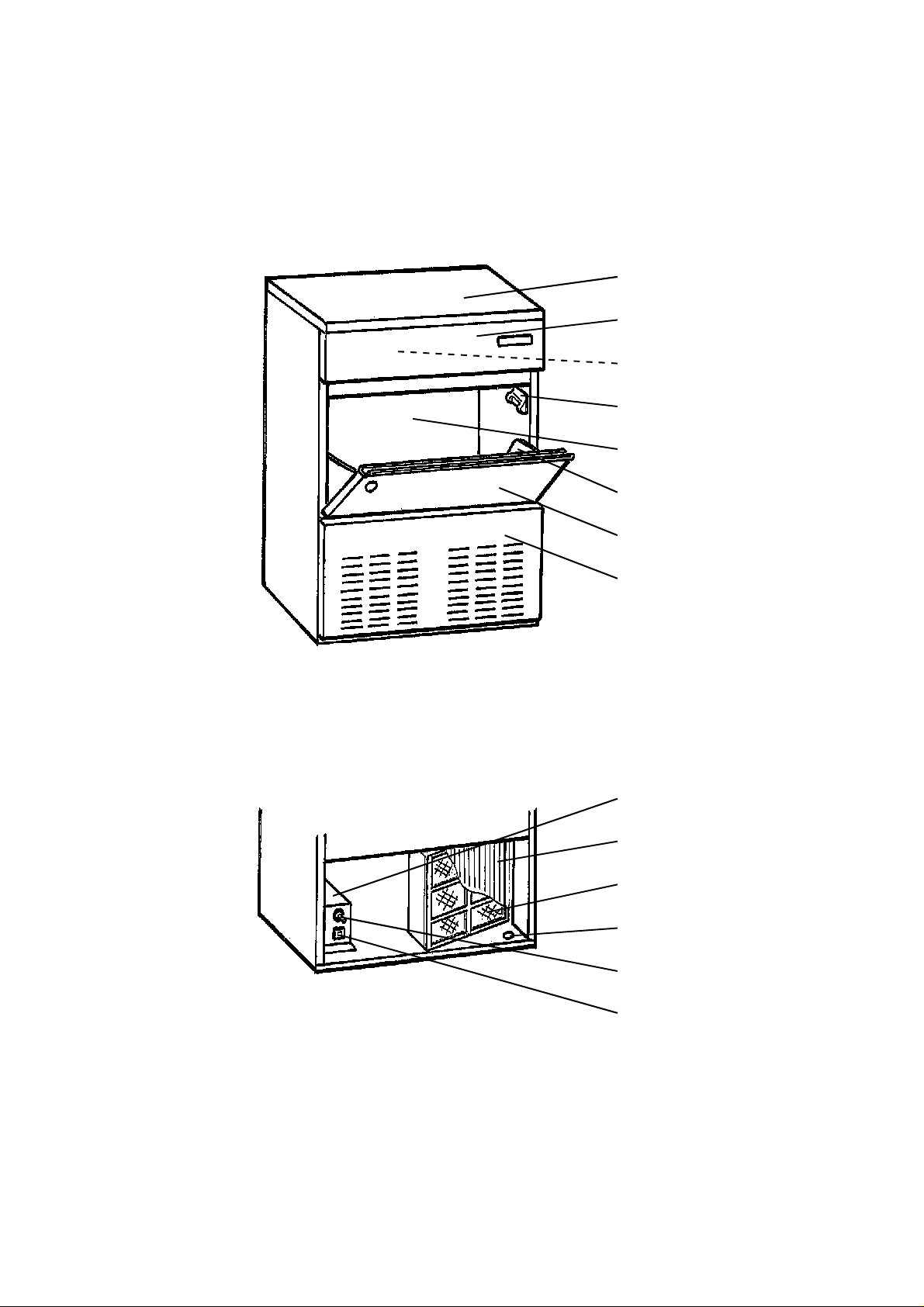
[a] AM-100BA E
Top Panel
Front Panel (Upper)
Ice Making Mechanism
Bin Control Thermostat
Storage Bin
Slope
Door
Front Panel (Lower)
Control Box
Condenser
Air Filter
Tapped Hole (Leg Moun ting)
Control Switch
Fuse
1
Page 5

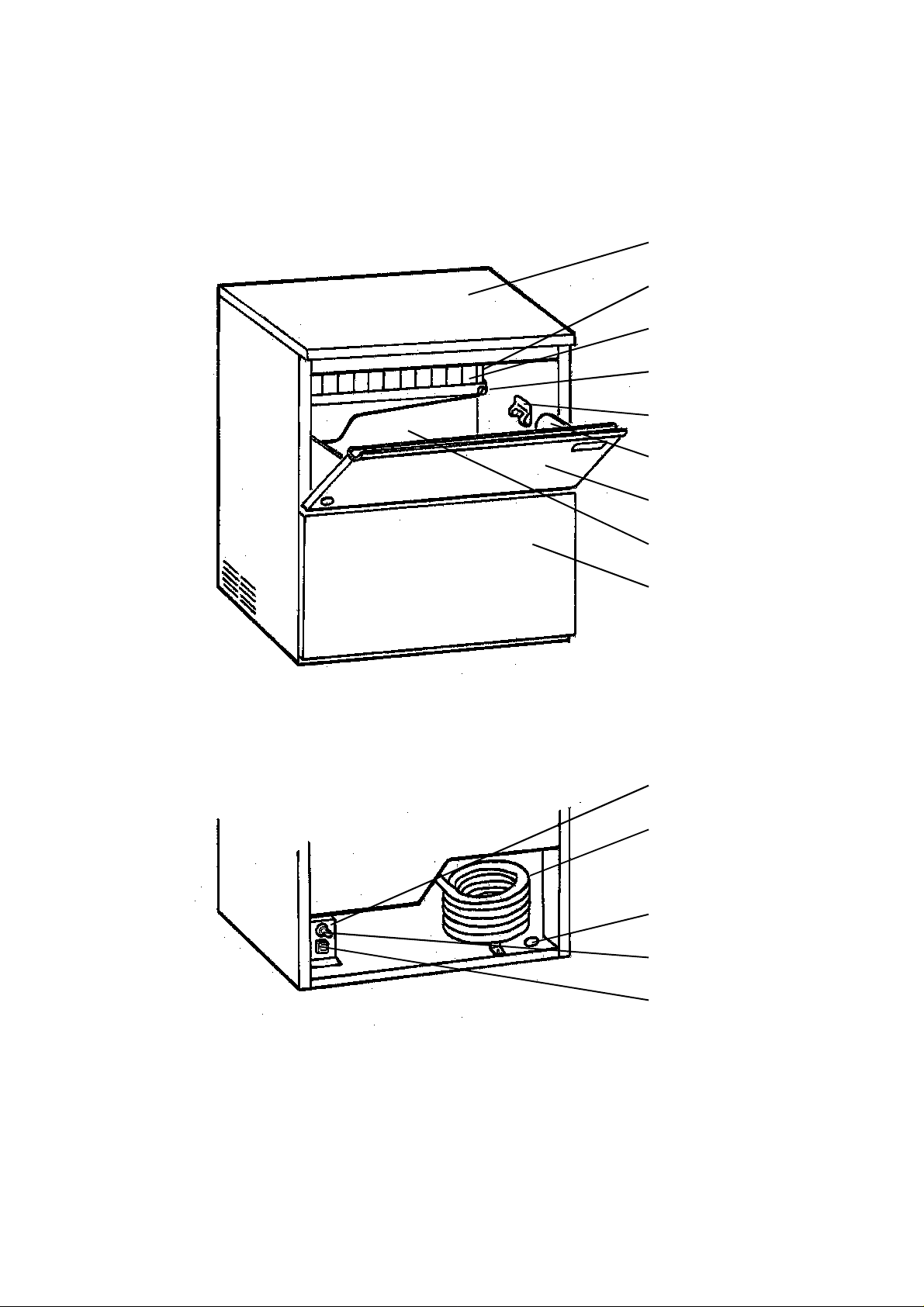
[b] AM-150BA F
Top Panel
Ice Making Mechanism
Separator
Water T ank
Bin Control Thermostat
Slope
Door
Storage Bin
Front Panel (Lower)
Control Box
Condenser
Air Filter
Tapped Hole (Leg Moun ting)
Control Switch
Fuse
2
Page 6
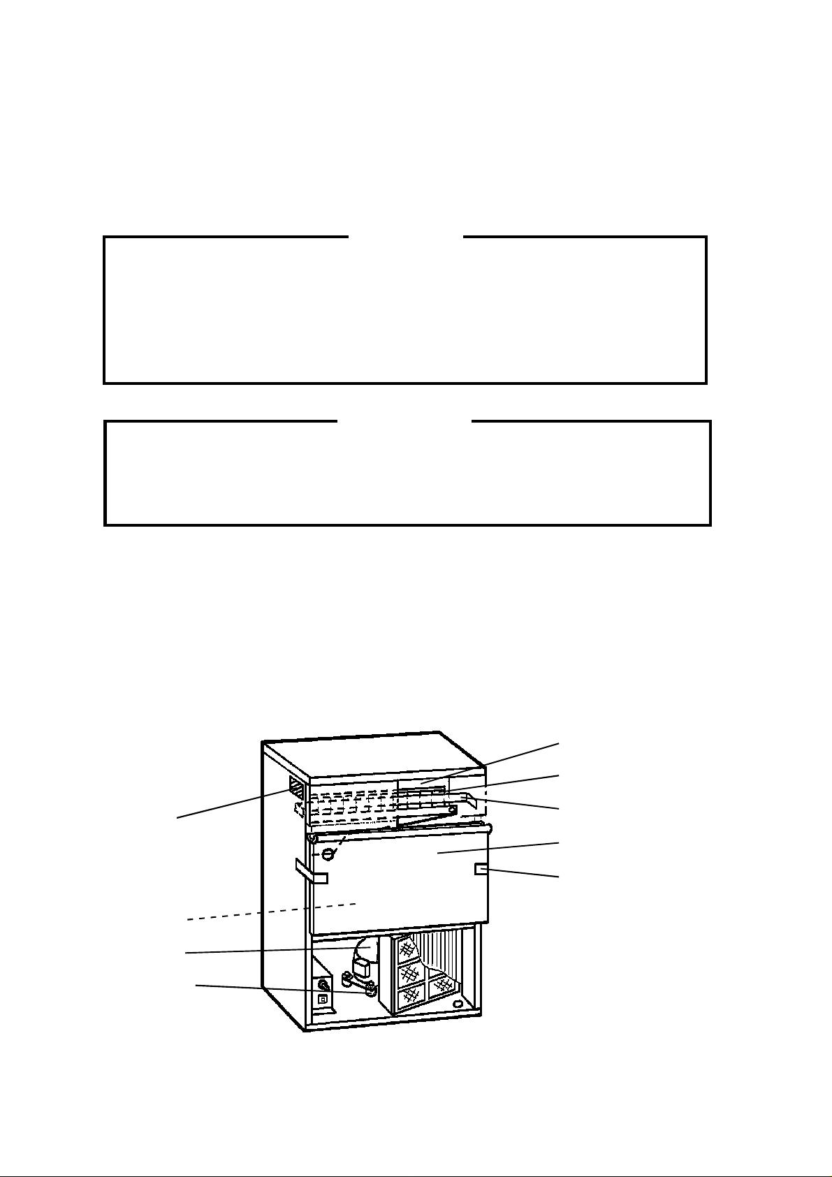
[c] AM-150BWF
Top Panel
Ice Making Mechanism
Separator
Water T ank
Bin Control Thermostat
Slope
Door
Storage Bin
Front Panel (Lower)
Control Box
Condenser
Tapped Hole (Leg Moun ting)
Control Switch
Fuse
3
Page 7
II. INSTALLATION AND OPERATING INSTRUCTIONS
1. CHECKS BEFORE INSTALLATION
* Visually inspect the exterior of the shipping container , and any severe damage noted should
be reported to the carrier.
W ARNING
1. Remove shipping t ape(s) and pack ing as fol lows . If any left i n the icem aker ,
it will not w ork proper ly .
2. Do not lift or carry t he unpacked ic emaker by us ing the bra ss fitting for water
supply at the r ear of the unit. The plasti c threads may be damaged.
IMPORTANT
1. Remove the shipping tapes holding the Door and Separator.
2. Ensure all components, fasteners an d thumbscr ews are securely in pl ace.
* Remove the package containing accessories.
* Check that refrig erant lines do n ot rub or touch li nes or other sur faces.
* Check that the Compr essor is snug on all mounting pads.
* See the Nameplate on the upper right part of the Left Side Panel, and check tha t your
voltage supplied cor responds with the voltage speci fied on the Nameplate.
Ice Making Mechanism
Separator
Nameplate
Shipping T ape
Door
Shipping T ape
Accessories
Compressor
Mounting Pad
Fig. 1
4
Page 8

2. LOCATION
W ARNING
This icemaker is not intended for outdoor use. Normal operating ambient
temperature should be within 50°F (10°C) to 100°F (38°C); Normal operating
water temp er a t ure should be within 41°F (5°C) to 90°F (32 °C). Operation of
the icemaker , for extended periods, outside of these normal temperature ranges
may affect production capaci ty .
For best operating results:
* The icemaker should not be located next to ovens, grills or other high heat producing
equipment.
* The location should provi de a firm foundation for the equipment. Lev el the i cemaker from
side to side and front to rear.
* Avoid a site w here drippi ng i s not allow ed.
* This icemaker will not work at subfreezing temperatures. To prevent damage to the water
supply line, drai n the icemaker when ai r temperature is below zero.
* The AM-100BAE icemaker requires no clearance at either side. But allow enough space
at rear for water supply and drain connections, at least 12” (approx. 30 cm) clearance at
front, and at least 0.6” (approx . 15 mm) cleara nce at top for main tenance.
* The AM-150BAF icemaker r equires 2” (approx . 5 cm) clearance at either side. Allow enoug h
space at rear for water supply and drain connections, at least 12” (approx. 30 cm) clearance
at front, and at least 0.6” (a pprox. 15 mm) cle arance at top for mai ntenance.
5
Page 9

3. SET UP
IMPORTANT
Do not place heavy objects exceeding 33 l bs (15 kg) on the Top Panel.
1) Unpack the icemaker, and remove all shipping cartons, tapes
and packing BEFORE operating the unit.
2) Position the i cemaker in a selected site. Clean the interior
with soap and w ater and rin se thoroughl y .
3) Level the ic emake r in bo th the l eft- to- r ig ht an d t he fr ont- t orear directions (when installed with or without legs). See Fig.
2.
4) When installing the unit without legs, the perimeter where the
machine touches the counter shoul d be sealed wi th silicone
to prevent wate r from leaking under the icemak er .
Max. 0.4” (1 c m)
Fig. 2
T apped Hole
(Leg Mounting)
5) When installin g the unit with legs on the botto m, use the four
accessory legs adjustable from 6” (15.2 cm) to 7” (17.8 cm).
Screw the legs tightly i nto the tapped holes in th e base (see
Fig. 3). Handle the icemaker carefully not to damage the
exterior.
Base
Adjustable Leg
Fig. 3
4. ELECTRICAL CONNECTIONS
W ARNING
THIS APPLIANCE MUST BE GROUNDED.
This icemaker requires a ground that meets the national and local electrical
code requirements. To prevent possib le severe electrical shock injury to
individuals or extensive damage to eq uipment, install a proper ground w ire to
this icemaker . Remove the plug from the mains socket before any maintenance,
repairs or cleaning is undertaken.
* This icemaker must be plug g ed i nto the separated power receptacle which has eno ugh
capacity. The maximum allow able vol tage v ariation should not exceed ± 10 percent of the
nameplate rating. See the Namepl ate.
* Usually an electrical permit and serv ices of a licensed electrician ar e required.
6
Page 10

5. WATE R SUPPLY AND DRAIN CONNECTIONS
W ARNING
To prevent damage to the freezer mechanism, do not operate this icemaker
when the w ater suppl y is OF F, or if the pr essure is below 10 PSIG (0. 7 bar), the
recommended water pressure. St op the icemaker until pr oper water pr essure
is resumed.
CAUTION
1. A brass fitting for the water supply line connection is attached to the 3/4” BSP
plastic threads to avoid cross-threading of the Water Valve possibly resulting
in leaks. The brass fitting allows connection of a 1/2” FPT that should be
connected to the potable w ater supply lin e.
2. While making the water supply line connection, use a wrench to hold the
brass fitting still to prevent overtightening and damage to the plastic threads.
* Water supply inlet for the i cemaker is 1/2” female pipe t hread (FPT).
Note: On water-cooled model, two water supply inlets are pro vided. One is for the i cemaker
(1/2” FPT), and the other is for the water -cooled condenser (1/2” FPT).
* The brass fitting is attached as shown in Fig. 4. The fitting size is a 1/2” FPT and must be
connected only to a pot able water supply.
* A water supply line shut-off valve and drain valve must be installed.
* Water supply pressure should be a mini mum of 10 PSIG (0.7 bar) and a maximum of 113
PSIG (7.5 bar). If the pressure exceeds 113 PSIG (7.5 bar), use a pressure reducing valve.
* Drain outlet for icemaker dump is 3/4” FPT.
Note: On water-cooled model, a 3/8” FPT is pr ovided for the con denser drain outlet. The
icemaker drain and the condenser drai n piping connecti ons must be made separate ly .
* Drain must be 1/4” fall per foot (2 cm fall per meter) on horiz ontal run s to get good flow.
* Keep a more than 2 vertical inch (5 vertical cm) air gap between the drain pipe end and the
sink.
* The drain pipe must be so laid as to prevent a backflow into the Storage Bin. Provide a trap
in the bin drain li ne to prev ent odor from flowi ng back into the S tor age Bin.
7
Page 11

* A plumbing permit and services of a licensed plumber may be required in some areas.
* This icemaker should be installed in accordance with applicable national, state and local
regulations.
AM-100BAE
AM-150BAF
Icemaker
Trap
1/4” fall per foot
Water Supply Inlet
3/4” BSP Threads
Brass fitting is attached
to Water Supply Inlet.
Fitting size is a 1/2” FPT.
Shut-off V alv e
Drain V alve
Bin Drain Outlet
3/4” FPT
AM-150BWF
Condenser Outlet
3/8” FPT
Water-cooled
Condenser Inlet
1/2” FPT
Drain V alve
T o approved floor drain
Icemaker
Water Supply Inlet
3/4” BSP Threads
Brass fitting is attached
to Water Supply Inlet.
Fitting size is a 1/2” FPT.
Shut-off V alve
Drain V alve
Bin Drain Outlet 3/4” FPT
1/4” fall per foot
T o approved floor drain
Shut-off V alv e
Trap
Fig. 4
8
Page 12

6. FINAL CHECK LIST
1) Is the icemaker lev el?
2) Is the icemaker in a site where the ambient temperature is within 50°F (10°C) to 100°F
(38°C) and the water temperature withi n 41°F (5°C) to 90°F ( 32°C) al l year ar ound?
3) Have all shipping tape(s), string and packing been removed from the icemaker?
4) Are all components, fastener s and thumbscrews se curely in place?
5) Have all electr ical and piping connections been made?
6) Has the power supply voltage been tested or checked against the nameplate rating?
Has a proper earth been installed to the icemaker?
7) Are the Water Supply Line Shut-off V alve and D rain V alve installed? Has the water supply
pressur e been che ck ed to en su re a mi ni mum o f 10 P SI G (0 .7 bar ) and a ma x i mum of
1 13 PSIG (7.5 bar)?
8) Have the Compressor hold-down bol ts and all refriger a nt l i ne s been check ed ag a i nst
vibration and possible failure?
9) Has the Bin Control Thermostat been checked for correct operation? When the icemaker
is running, cool the Detector of the Bin Control Thermostat. The icemaker should stop
within 10 seconds.
10)Has the user been given the Instr uction Manual and instructed on how to operate the
icemaker and the importance of periodic maintenance recommended?
11) Has the user been given the name and telephone number of the Autho rized Service
Agency?
7. START UP
* Check that shipping tape(s), str ing and packing are r emoved before starting the i cemaker .
1) Clean inside the Storage Bin and Door.
2) Open the Water Supply L ine Shut-of f V alv e and plug in the ice maker .
3) Remove the Fr ont Panel ( Lower) , and move the Control S witch on the Control Box t o the
“ICE” position.
* The freezing cycle w ill start automatically.
9
Page 13

8. PREPARI NG THE ICEM AKER FOR LONG STORAGE (more t han 1
day)
W ARNING
Drain the icemaker to prevent damage to the water supply line at subfreezing
temperatures, using air or carbon dioxide. Shut off the icemaker until proper air
temperature is resumed.
[1] On water- cooled model o nly, first remov e the wat er from the w ater-cool ed condenser:
1) Remove th e Front Panel (L ower).
Icemaker
2) Move the Control Switch, on the Control
Box, to the “OFF” position.
Potable Water
Supply Line
3) Wait 3 mi nutes.
Shut-off V alv e
4) Move the Control Switch to the “ICE”
position.
5) Allow 5 mi nutes for the icemaker to fill with
water and the Water Pump to start
operating.
6)Close the Water-cooled Condenser
Air or CO
Water-cooled Condenser
Water Supply Line
Drain V alve
2
Shut-off V alve
Water Supply Line Shut-off Valve.
7) Open the Drai n Val ve for the water- cooled
condenser w ater supply line.
8) Allow th e line to drai n by grav ity.
Air or CO
Fig. 5
Drain V alve
2
9) At tach co mpres sed air or carbon dioxide supply to the Co ndens er Wate r Line Drain
Valve.
10) Blow t he water- cooled condenser out usin g compres sed air or carbon diox ide until water
stops coming out.
[2] Remove t he wa ter from the potable water supply line and the Water Tank:
1) Close the Water Supply L ine Shut-of f V alv e, and open the D rain Valve.
2) Remove the Front Panel (Lower), and move the Control Sw itch, on the Control Box, to the
“OFF” position.
10
Page 14

3) Blow ou t the water sup ply lin e.
Note: This procedure i s necessary to protect the icemaker from freez ing up at subfreezing
temperature.
4) Unplug t he icemaker .
5) Remove all ice from the St orage Bin, and clean the Bin.
6) Drain an d clean the Water Tank . See “III. 1 . [b] STOR AGE BIN, SLO PE, SCOOP, ETC.”
7) Refit the Front Panel (Lower) in its correct posit ion.
8) Close the Drain Valve.
11
Page 15

III. MAINTENANCE AND CLEANING INSTRUCTIONS
IMPORTANT
Ensure all components, fastener s and thumbs crews ar e securely in place a fter
any maintenance or cleani ng is done t o the equi pment.
1. CLEANING INSTRUCTIONS
W ARNING
1. HOSHIZAKI recommends cleaning this unit at least once a year. More
frequent cleaning, however, may be required in some existing water conditions.
2. To prevent injury to individuals an d damage to th e icem aker, do not use
ammonia type cleaner s.
3. Always wear liquid-proof gloves for safe handling of the cleaning and sanitizing
solutions. This will prevent irritation in case the solution comes into contact
with skin.
[a] W ATER SYSTEM
1) Dilute approx imately 5 fl. oz . (148 ml) of recommended cl eaner Hoshiz aki “Scal e Away ”
or “LIME-A -WA Y ” (Economics Laborator y , Inc.) w ith 1 ga l. (3.8 li t.) of wat er .
2) Remove all i ce from the Evaporator and the Storage Bi n.
Note: To remove cubes on the Evaporator, remove the Front Panel (Lower), move the
Control Swi tch on the Cont rol Bo x to the “OF F” posi tion and mo v e it bac k to the
“ICE” position after 3 minutes. The defrost cycle starts and the cubes will be
removed from the Evap orator .
3) Move the Control Switch to the “OFF” po si t i on. Close the Water Supply Line Sh ut- o ff
Valve.
4) Remove the Water Tank to drain the water . Refit the Wa ter Tank in its correct positi on.
5) Slowly pour the cleaning solution into the Water Tank.
6) Move the Control Switch to the “WASH” position.
7) After circulating the cleaning solution for about 30 minutes, move the Control Swi tch to the
“OFF” position.
12
Page 16

8) Remove the Water T ank to drain the cleaning solution. Refit the Water T ank in it s correct
position.
9) Open the Shut-off Valve.
10) Move the Control Switch to the “WA SH” position to circulate clean water for a bout 5
minutes.
11) Move the Control Switch to the “OFF” position and immediately back to the “WASH”
position to rinse water .
12) Repeat the above ri nse procedure three more times to rin se thoroughly.
13) Dilute approximately 0.5 fl. oz. (14.8 ml) of 5.25% Sodium Hypochlorite (Chlorine Bleach)
with 1 gal. (3.8 lit.) of water.
14) Move th e Control Switch to the “ OFF” position. Close the Water Supply Line Shut-o f f
Valve.
15) Remove the Water Tank to drain the water . Refit the Water Tank in its correct positi on.
16) Slowly pour the san itizing solution in to the Water Tank.
17) Move the Control Switch to the “WASH” posi tion.
18) After circulating the sani tizing sol ution for about 15 minutes, move the Control Switch to
the “OFF” position.
19) Remove the Water T ank to drain the sanitizing solution. Refit the Water T ank in it s correct
position.
20) Open t he Shut-of f V alv e.
21) Move the Control Switch to the “WA SH” position to circulate clean water for a bout 5
minutes.
22) Move the Control Switch to the “OFF” position and immediately back to the “WASH”
position to rinse water .
23) Repeat the above rinse procedur e two more times to rinse thoro ughly.
24) Move the Control Switch to the “ICE” position, and start the automatic icemaking process.
Refit the Front Panel (Lower) in its correct position.
13
Page 17

[b] STORAGE BIN, SLOPE, SCOOP, ETC.
IMPORTANT
1. Wash your hands before removing ice. Use the Plastic Scoop provided to
remove ice.
2. Keep the Scoop clean. Clean i t by using a neutra l cleaner at least once a
day , and rinse thoroughly.
3. Close the Bin Door after removing ice to prevent entrance of dirt, dust or
insects into the Bin.
4. Clean the Bin Liner at least onc e a month by using a neutral cleaner. Rinse
thoroughly after cleaning.
5. The S torag e Bin is for ice use only. Do not store anything el se in the Bin.
6. Keep the area around the ic emaker clean. Dirt, dust or insects in the icemaker
could cause electrical damage to the equipment or harm to individual s.
1) Remove the Fr ont Panel (Low er), and move the Contr ol Swi tch on the Contr ol Box to the
“OFF” position.
2) Unplug the ic emaker .
3) Open the Bin Door , and remove ice from the S torage Bi n.
4) Remove the Slope by bending its center carefully and releasing it from th e two Slope
Shafts. Take out the Slope from the Sto rage Bin.
5) Thoroughly clean and sanitize the Storage Bin, Slope, Scoop and any parts normally
accessible from the Storage Bin.
6) Remove each Separator by lifting it to the
Separator
horizontal position and pushing it hard inwa rd.
Remove all the Separators in the same way,
and clean and san itize them.
7) Disconnect the Suction Tube from the Water
T ank to drain the T ank.
14
Water Tank
Suction Tube
Page 18

8) Remove the Thumbscrews on both sides of the
Water Tank, and pull it out toward you. Clean
and saniti ze the Wat er Tank.
Water Tank
Thumbscrew
9) Pull the Discharg e Tu be from the Water Plate.
Remove the Water Plate by pulling it toward you.
10) Remove the Caps to clean and sanitize the
Water Plat e. If the Noz zles are clogg ed, clean
them with a wir e or a suitable brush.
1 1) Refit the Caps on the C leaning Outlet s to seal
them off.
12) Slide in th e Water Plate al ong the M echanism
Base. Refit the Discharge Tube securely on
the Spray Outlet. A loose fitting may cause a
water leak.
Water Pla t e
Discharge Tube
Cap
Water Pla t e
Cap
Water Pla t e
Water Pla t e
13) Place th e rear of the Water Tank on the Water
Tank Rest at the bac k of the S torag e Bin. U se
the Thumbscrews to secure the f ront of the
Water Tank to the Mechanism Base.
14) Refit the Suction T ube on to the Water T ank Inlet.
A loose fitting may cause a water leak.
15
Water Tank
Mechan ism Ba se
Thumbscrew
Discharge Tube
Bin Rear
Tank Rest
Water Tank
Suction Tube
Page 19

15) Hook each Separator on to the Mechanism
Base, and pull it hard toward you until it locks in
place with a click. Refit all the Separators in
the same way.
16) Refit the Slope in its correct position.
17) Plug in the icemaker , and move the Contr ol Switch on the Control Box to the “ ICE” position
to start the automatic icemaking process.
18) Refit the Front Panel (Lower) in its correct position.
Separator
2. MAINTENANCE
IMPORTANT
This icemaker must be maintained indi vidually , referring to the instruction manual
and labels provided wi th the icemaker .
1) Exterior
To keep the exte rior cl ean, wi pe occasiona lly w ith a cl ean and soft cloth. U se a damp
cloth containing a neut ral cleaner t o wipe off all oil or dirt buil d-up.
2) Air F ilt er
A pla stic mesh air fil ter remov es di rt or dust from the air, and keeps the Condenser
from getting clogged. As the filter gets clogged, the icemaker’s performance will be
reduced. Check the filter at least twice a month. When clogged, use warm water and
a neutral cleaner to wash the filter.
3) Condenser
Check the Condenser once a year, and clean if required by us ing a brush or v acuum
cleaner. More frequent cleaning may be required dependi n g on the location of the
icemaker.
16
Page 20

(
)
A
Bin Control Thermostat Replacement Procedure
To ensure proper operation, follow the instructions below:
[AM-100BAE]
1) Make a 40 mm (1.6”) diameter loop.
2) Locate the loop below the Thermostat
Capillary (Bulb).
3) Manually bend the Capillary to keep it
15 mm (0.6”) forward from the through
hole position on the Holder.
4) Turn up the end of the Capillary.
Through Hole
Loop
40 mm (1.6”) DIA
Bin Control Thermostat Assembly Details
[NOTE]
1) Run Cord Heater along with Capillary of Thermostat and bind them tightly with
Aluminum Tape (Form end to end of Cord Heater).
2) Do not overheat Flexible Tube during shrinking process.
Capillary (Bulb)
Thermostat
Cord Heater
Flexible Tube
SERVICE INSTRUCTIONS
[AM-150BAF/BWF]
1) Make a 40 mm (1.6”) ID U-bend.
2) Locate the U-bend 60 mm (2.4”) below
the Thermostat Ca pillary (Bulb).
3) Manually bend the Capillary to keep it
15 mm (0.6”) forward from the through
hole position on the Holder.
4) Turn up the end of the Capillary.
Holder
Capillary (Bulb)
End
15 mm (0.6”)
Silicone Tube
DETAIL A
Through Hole
60 mm (2.4”)
40 mm (1.6”)
Silicone Tube
17
Seal
Capillary (Bulb)
150mm
210mm
Bracket - Holder
Holder
Capillary (Bulb)
End
15 mm (0.6”)
Capillary (Bulb)
(5.9”)
8.3”
Page 21

HOSHIZAKI AMERICA, INC.
618 HIGHWAY 74 SOUTH
PEACHTREE CITY , GA 30269
U.S.A.
PHONE: 770-487-2331
www.hoshizakiamerica.com
9117EA10H
 Loading...