

Page 1

Hoshizaki America, Inc.
Hoshizaki
Commercial Refrigerators & Freezers
®
TempGuard Dual Temp Series
“A Superior Degree
of Reliability”
Models
RFH2-SSB(-HD)
RFH3-SSB(-HD)
PARTS LIST
www.hoshizaki.com
Number: 71227
Issued: 3-8-1999
Revised: 8-30-2007
Page 2

CONTENTS
Auxiliary Codes ...................................................................................................................... 4
Note About Ordering Parts .................................................................................................... 4
Material Abbreviations ........................................................................................................... 5
A. Reach-In ............................................................................................................................ 6
RFH2-SSB(-HD) ............................................................................................................... 6
RFH3-SSB(-HD) ................................................................................................................ 9
B. Refrigeration Assembly ................................................................................................... 12
RFH2-SSB(-HD) Refrigerator 1 Section .......................................................................... 12
RFH3-SSB(-HD) Refrigerator 2 Section .......................................................................... 15
RFH2-SSB(-HD), RFH3-SSB(-HD) Freezer 1 Section .................................................... 18
C. Control Panel Assembly .................................................................................................. 21
RFH2-SSB(-HD) .............................................................................................................. 21
RFH3-SSB(-HD) .............................................................................................................. 23
D. Body-Final ....................................................................................................................... 25
RFH2-SSB ...................................................................................................................... 25
RFH2-SSB-HD ................................................................................................................ 27
RFH3-SSB ...................................................................................................................... 29
RFH3-SSB-HD ................................................................................................................ 31
E. Panel-Front Hinged Assembly ......................................................................................... 33
RFH2-SSB(-HD), RFH3-SSB(-HD) ................................................................................. 33
F. Label Location .................................................................................................................. 34
RFH2-SSB(-HD) .............................................................................................................. 34
RFH3-SSB(-HD) .............................................................................................................. 36
G. Breaker Box Assembly .................................................................................................... 38
RFH2-SSB(-HD), RFH3-SSB-(HD) ................................................................................. 38
H. Control Box Assembly ..................................................................................................... 39
RFH2-SSB(-HD) Refrigerator 1 Section .......................................................................... 39
RFH3-SSB(-HD) Refrigerator 2 Section .......................................................................... 40
RFH2-SSB(-HD), RFH3-SSB(-HD) Freezer 1 Section .................................................... 41
J. Evaporator Fan Shroud Assembly ................................................................................... 43
RFH2-SSB(-HD) Refrigerator 1 Section .......................................................................... 43
RFH3-SSB(-HD) Refrigerator 2 Section .......................................................................... 45
RFH2-SSB(-HD), RFH3-SSB(-HD) Freezer 1 Section ................................................... 46
K. Evaporator Assembly ...................................................................................................... 48
RFH2-SSB(-HD) Refrigerator 1 Section .......................................................................... 48
RFH3-SSB(-HD) Refrigerator 2 Section .......................................................................... 49
RFH2-SSB(-HD), RFH3-SSB(-HD) Freezer 1 Section .................................................... 50
L. Condenser Assembly ....................................................................................................... 52
RFH2-SSB(-HD) Refrigerator 1 Section .......................................................................... 52
RFH3-SSB(-HD) Refrigerator 2 Section .......................................................................... 54
RFH2-SSB(-HD), RFH3-SSB(-HD) Freezer 1 Section .................................................... 57
M. Body-Prefinal .................................................................................................................. 60
RFH2-SSB(-HD) .............................................................................................................. 60
RFH3-SSB(-HD) .............................................................................................................. 62
N. Door-Full (R) ................................................................................................................... 65
RFH2-SSB, RFH3-SSB ................................................................................................... 65
2
Page 3

P. Door-Full (L) ..................................................................................................................... 67
RFH2-SSB, RFH3-SSB ................................................................................................... 67
Q. Door-Half (UR) ................................................................................................................ 69
RFH2-SSB-HD, RFH3-SSB-HD ...................................................................................... 69
R. Door-Half (LR) ................................................................................................................. 71
RFH2-SSB-HD, RFH3-SSB-HD ...................................................................................... 71
S. Door-Half (UL) ................................................................................................................. 73
RFH2-SSB-HD, RFH3-SSB-HD ...................................................................................... 73
T. Door-Half (LL) .................................................................................................................. 75
RFH2-SSB-HD, RFH3-SSB-HD ...................................................................................... 75
U. Mullion-Horizontal............................................................................................................ 77
RFH2-SSB-HD, RFH3-SSB-HD ...................................................................................... 77
V. Mullion-Vertical ................................................................................................................ 78
RFH3-SSB ...................................................................................................................... 78
W. Mullion-Cross .................................................................................................................. 80
RFH3-SSB-HD ................................................................................................................ 80
X. Common Control Box ..................................................................................................... 82
Y. Distributor-Air Top Assembly ............................................................................................ 84
RFH2-SSB(-HD), RFH3-SSB(-HD) Freezer 1 Section .................................................... 84
Z. Literature & Packaging .................................................................................................... 85
3
Page 4

Auxiliary Codes
RFH2-SSB J-0 January 1999
J-1 September 1999
J-2 October 1999
K-0 January 2000
L-5 January 2001
M-5 January 2002
N-6 June 2003
P-6 March 2004
Q-5 January 2005
R-5 January 2006
S-5 January 2007
S-6 February 2007
RFH2-SSB-HD J-0 February 1999
J-1 September 1999
J-2 October 1999
K-0 January 2000
L-5 January 2001
M-5 January 2002
N-6 June 2003
P-6 March 2004
Q-5 January 2005
R-5 January 2006
S-6 April 2007
RFH3-SSB J-0 March 1999
J-1 September 1999
J-2 October 1999
K-0 January 2000
L-5 January 2001
M-5 January 2002
N-6 June 2003
P-6 March 2004
Q-5 January 2005
R-5 July 2006
S-6 March 2007
RFH3-SSB-HD J-0 March 1999
J-1 September 1999
J-2 October 1999
K-0 January 2000
L-5 January 2001
M-5 May 2002
N-6 June 2003
P-6 March 2004
Q-5 January 2005
S-6 April 2007
Auxiliary Code Breakdown
K-5
Designates the year. "K" indicates the year 2000. Years progress or regress in alphabetical order.
"J" is 1999, "L" is 2001, "M" is 2002, and so on. The letters "I" and "O" were skipped.
Designates significant part changes within the same year for this model. Base is 5 (0 for auxiliary
codes J and K) and this number advances for each change.
Example: P-6
"P" indicates 2004.
"6" indicates the first significant part change for 2004.
Note About Ordering Parts
Most assemblies cannot be ordered as complete units; parts in the assemblies generally must be ordered
separately.
4
Page 5

Material Abbreviations
ALUMINUM
AL = Aluminum
COPPER
CU = Copper
PLASTIC
ABS = Acrylonitrile -butadiene - styrene
AC = Polyacetal
EVA = Ethylene vinyl acetate
PA = Polyamide = Nylon
PC = Polycarbonate
PE = Polyethylene
PES = Polyester
PETP = Polyethylene terephthalate = Tetlon
PP = Polypropylene
PS = Polystyrene
PTFE = Polytetrafluoroethylene = Teflon
PUR = Polyurethane
PVC = Polyvinyl chloride
RUBBER
VN = Vinyl Nitrile
EPDM = EP rubber
NBR = Nitrile butadiene rubber
NR = Natural rubber
NP = Neoprene
SI.R = Silicone rubber
SY.R = Synthetic rubber
EPH = Epichlorohydrin
STEEL
GS = Galvanized steel
SS = Stainless steel
PS = Plated steel
PAS = Primed steel
5
Page 6
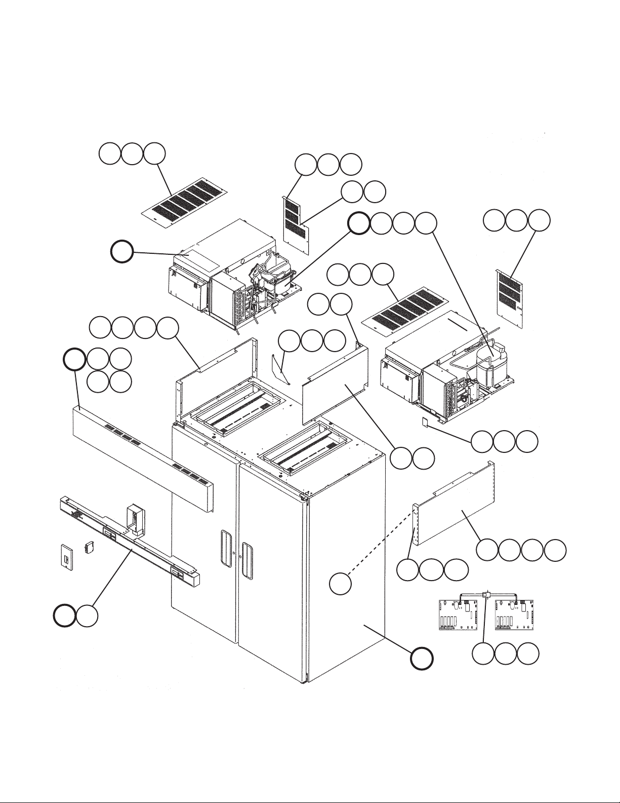
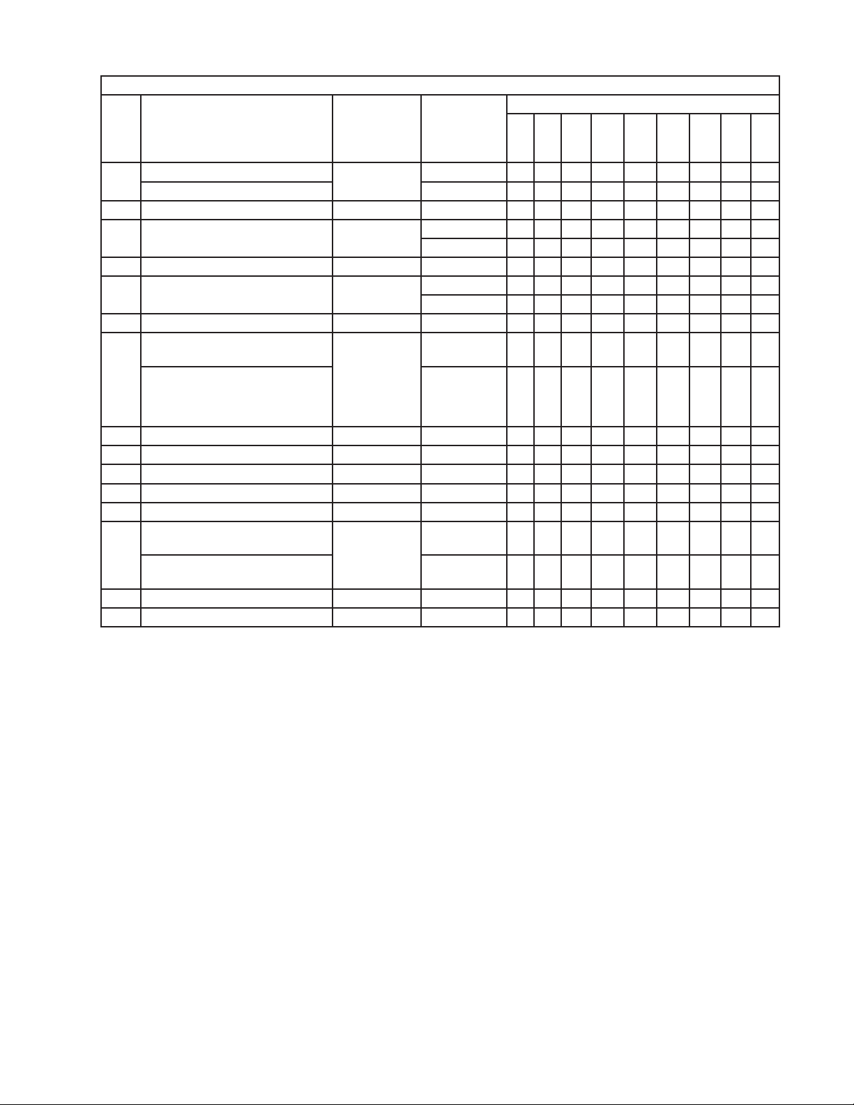
A. Reach-In
RFH2-SSB(-HD)
J-0, J-1, J-2, K-0, L-5, M-5, N-6, P-6, Q-5, R-5, S-5, S-6
3b
3a
3
4
F
Refrigerator 1 Section
11 12
2a 2b
2
2c
1
1a 1b
4a
4b
11 12
5
B
5a
B1
5b
B3B2
6
6b
6a
C
E
E1 E2
E3 E4
C1
10
Freezer 1 Section
7a 7b
7
8a
8
2a 2b
2
9a
9
9b
2c
D
6
13 14 15
Page 7

Title: A. Reach-In Model: RFH2-SSB(-HD)
Required Number
J-1
Index
No. Description
B Refrigeration Assembly Refrigerator -
B1 Bolt Assembly 8×60 437889-01 10 10 10 10 10 10
B2 Truss Head Screw 5×25, SS 7C32-0525 4 4 4 4 4 4
B3 Washer M8, SS 7W22-0800 4 4 4 4 4 4
C Control Panel Assembly - 2A1371A01 1 1 1 1 1 1
C1 T2 Screw 4×8, SS 7P32-0408 8 8 8 8 8 8
D Body-Final
E Panel-Front - 1A0040-01 1 1 -
Panel-Front Hinged Assembly - 2A2011A02 1 1 1 1
E1 Clevis Pin - 8907-0102 2 2 2 2
E2 Cotter Pin - 8907-0103 2 2 2 2
E3 Flat Washer SS 4A0655-03 2 2 2 2
E4 Spacer-Hinge PA 4A2473-01 2 2 2 2
F Label Location
Material or
Model Number Part Number
1A0297A01 1 1 1 1 1 1
1 section
Freezer1 section
RFH2-SSB
RFH2-SSB-HD
RFH2-SSB
RFH2-SSB-HD
1A0278A01 1 1 1 1 1 1
2A1362A01 1 1 1 1 1 1
2A1418A01 1 1 1 1 1 1
2A1381G01 1 1 1 1 1 1
2A1381G02 1 1 1 1 1 1
J-0
to
K-0
L-5
M-5
N-6
P-6
Q-5
R-5
S-5
S-6
1 Gusset-Side, Top GS 3A1006-01 1 1 -
Gusset-Frame 3A1520-01 1 -
4A2845-01 1 -
4A3856-01 1 1
1a T2 Screw 4×8, SS 7P32-0408 2 2 4 4 4 4
1b Truss Head Screw 5×10, SS 7C32-0510 2 2
2 Panel-Side, Top SS 2A0615-02 2 2 -
2A1800-01 2 2 2 2
2a Taper Collar - 4H0171-01 4 4 4 4 4 4
2b Countersunk Screw 5×20, SS 7C42-0520 4 4 4 4 4 4
2c Truss Head Screw 5×10, SS 7C32-0510 2 2 2 2
3 Top UL Cover Assembly Refrigerator, GS 2A1305G01 1 1 1 -
2A2757G01 1 1 1
3a Truss Head Screw 5×10, SS 7C32-0510 2 2
3b T2 Screw 4×8, SS 7P32-0408 2 2 5 5 5 5
4 Rear UL Cover Refrigerator, GS 2A1357G01 1 -
2A1633-01 1 1 -
2A2754-01 1 1 1
4a Truss Head Screw 5×10, SS 7C32-0510 2 3
4b T2 Screw 4×8, SS 7P32-0408 2 2 5 5 5 5
5 Top UL Cover Freezer, GS 2A0955-01 1 1 1 -
2A2751-01 1 1 -
2A2755-01 1
5a Truss Head Screw 5×10, SS 7C32-0510 3 3
5b T2 Screw 4×8, SS 7P32-0408 2 2 5 5 5 5
7
Page 8

Title: A. Reach-In Model: RFH2-SSB(-HD)
Required Number
J-1
Index
No. Description
6 Rear UL Cover Freezer, GS 2A0956-01 1 1 1 -
6a Truss Head Screw 5×10, SS 7C32-0510 2 2
6b T2 Screw 4×8, SS 7P32-0408 2 2 4 4 4 4
7 Junction Box Cover GS 433410-01 1 -
7a T2 Screw 4×8, SS 7P32-0408 1 1 1 1 1 1
7b Bushing - 420472-01 1 -
8 Panel-Division GS 3A1173-01 1 -
8a T2 Screw 4×8, SS 7P32-0408 3 3 3 3 3 3
9 Frame-Side Top GS 2A1803-01 2 2 2 2 2
9a Truss Head Screw 5×10, SS 7C32-0510 8 8 8 8 8
9b T2 Screw 4×8, SS 7P32-0408 4 4 4 4 4
10 Bracket-Hinge GS 4A2306-01 2 2 2 2 2
11 Grounding Screw M5 433304-02 1 1 1 1 1 1
12 Square Washer - 433537-02 1 1 1 1
13 Data Cable L=1030 4A1801L01 1 1 -
14 Receptacle Housing (2 pin) 3191-02R 412831-07 1 1 1 1
15 Plug Housing (2 pin) 3191-02P 412832-07 1 1 1 1
Material or
Model Number Part Number
2A2752-01 1 1 -
2A4261-01 1
4A1992-01 1 1 1 1 1
420472-05 1 1 1 1 1
3A1423G01 1 1 1 1 1
L=800 2 2 2 2
J-0
to
K-0
L-5
M-5
N-6
P-6
Q-5
R-5
S-5
S-6
8
Page 9
A. Reach-In
RFH3-SSB(-HD)
J-0, J-1, J-2, K-0, L-5, M-5, N-6, P-6, Q-5, R-5, S-6
2
E1 E2 E3 E4
E
2a 2b
11a
11
G
15
G1
2c
G2 G3
15a
Refrigerator - 2 Section
F
1a
1
1b
8a
8
3
12
13
3b3a
4a
4
B
5a
5
5b
4b
B3B1 B2
6a
6
6b
C
C1
16
17
18
14
D
10
Freezer - 1 Section
7a
7
11a
11
9
2a
2
19
7b
2b 2c
20
9
Page 10

Title: A. Reach-In Model: RFH3-SSB(-HD)
Index
No. Description
B Refrigeration Assembly Refrigerator-
B1 Bolt Assembly Refrigerator,
B2 Hex Bolt Refrigerator,
Truss Head Screw Freezer, 5×25, SS7C32-0525 2 2 2 2 2 2 2 2
Material or
Model Number Part Number
2 section
Freezer1 section
8×45
Freezer, 8×45 5 5 5 5 5 5 5 5
8×70
Required Number
J-1
J-0
J-2 K-0 L-5 M-5
1A0319A01 1 1 1 1 1 1 1 1
1A0278A01 1 1 1 1 1 1 1 1
437889-01 6 6 6 6 6 6 6 6
7B01-0870 2 2 2 2 2 2 2 2
N-6
P-6
Q-5
R-5 S-6
B3 Washer Refrigerator,
M8, SS
Freezer, M5, SS 7W22-0500 2 2 2 2 2 2 2 2
C Control Panel Assembly - 2A1408A01 1 1 1 1 1 1 1 1
C1 T2 Screw 4×8, SS 7P32-0408 12 12 12 12 12 12 12 12
D Body-Final
E Panel-Front - 1A0286-01 1 1 1 -
Panel-Front Hinged Assembly - 2A2011A03 1 1 1 1 1
E1 Clevis Pin 8907-0102 2 2 2 2 2
E2 Cotter Pin
E3 Flat Washer - 4A0655-03 2 2 2 2 2
E4 Spacer-Hinge - 4A2473-01 2 2 2 2 2
F Label Location
G Breaker Box Assembly - 3A1377A01 1 1 1 1 1 1 1 1
G1 Truss Head Screw 4×16, SS 7C32-0416 3 3 3 3 3 3 3 3
G2 T2 Screw 4×8, SS 7P32-0408 1 1 1 1 1 1 1 1
G3 Truss Head Screw 5×10, SS 7C32-0510 2 2 2 2 2 2 2 2
1 Gusset-Side, Top GS 3A1006-01 1 1 -
Gusset-Frame 3A1520-01 1 1 -
1a T2 Screw 4×8, SS 7P32-0408 8 8 4 4 4 4 4 4
1b Truss Head Screw 5×10, SS 7C32-0510 2 2 -
2 Panel-Side, Top SS 2A0615-02 2 2 -
2a Taper Collar SS 4H0171-01 4 4 4 4 4 4 4 4
2b Countersunk Screw 5×20, SS 7C42-0520 4 4 4 4 4 4 4 4
2c Truss Head Screw 5×10, SS 7C32-0510 2 2 2 2 2 2
3 Top UL Cover Refrigerator, GS 2A1118-01 1 -
3a Truss Head Screw 5×10, SS 7C32-0510 3 3 -
3b T2 Screw 4×8, SS 7P32-0408 3 3 6 6
RFH3-SSB
RFH3-SSB-HD
-
RFH3-SSB
RFH3-SSB-HD
7W22-0800 2 2 2 2 2 2 2 2
1A0393A01 1 1 1 1 1 1 1 1
2A1440A01 1 1 1 1 1 1 1 1
8907-0103 2 2 2 2 2
2A1415G01 1 1 1 1 1 1 1 1
2A1415G02 1 1 1 1 1 1 1 1
4A2845-01 1 1 -
4A3856-01 1 1
2A1800-01 2 2 2 2 2 2
2A1118-02 1 1 1 1 1 1 1
6 6 6 6
10
Page 11
Title: A. Reach-In Model: RFH3-SSB(-HD)
Required Number
Index
No. Description
4 Rear UL Cover Assembly Refrigerator, GS 2A1406G01 1 -
Rear UL Cover 2A1632-01 1 1 1 1 1 1 1
4a Truss Head Screw 5×10, SS 7C32-0510 2 3 -
4b T2 Screw 4×8, SS 7P32-0408 3 3 6 6 6 6 6 6
5 Top UL Cover Freezer, GS 2A0955-01 1 1 1 1 1 -
5a Truss Head Screw 5×10, SS 7C32-0510 6 3 -
5b T2 Screw 4×8, SS 7P32-0408 4 2 5 5 5 5 5 5
6 Rear UL Cover Freezer, GS 2A0956-01 1 1 1 1 1 -
6a Truss Head Screw 5×10, SS 7C32-0510 3 3
6b T2 Screw 4×8, SS 7P32-0408 2 2 4 4 4 4 4 4
7 Junction Box Cover GS 433410-01 1 -
Cover-Junction Box 4A1992-01 1 1 1 1 1 1 1
7a T2 Screw 4×8, SS 7P32-0408 1 1 1 1 1 1 1 1
7b Bushing - 420472-01 1 -
8 Panel-Division GS 3A1173-01 1 -
8a T2 Screw 4×8, SS 7P32-0408 3 3 3 3 3 3 3 3
9 Bracket-Hinge - 4A2306-01 2 2 2 2 2
10 Tee-Tubing - 4A1822-01 1 1 1 1 1 1 1 1
11 Frame-Side Top GS 2A1803-01 2 2 2 2
11a Truss Head Screw 5×10, SS 7C32-0510 8 8 8 8
12 Grounding Screw
13 Square Washer
14 Clamp - 427902-05 4 4 4 4 4 4 4
15 Distributor-Air Top - 1A0152-01 1 1 1 1 1 1 1
15a T2 Screw 4×8, SS 7P32-0408 7 7 7 7 7 7 7
16 Data Cable - 4A1801-01 1 1 -
17 Receptacle Housing Refrigerator
18 Plug Houshing Freezer (2 pin) 412832-07 1 1 1 1 1 1
19 Vinyl Hose L=280 7716-0913 1 1 -
20 Vinyl Hose L=680 7716-0913 1 1 -
Material or
Model Number Part Number
2A2751-01 1 1 -
2A2755-01 1
2A2752-01 1 1 -
2A4261-01 1
420472-05 1 1 1 1 1 1 1
3A1423G01 1 1 1 1 1 1 1
-
-
L=1150 4A1801L01 2 2 2 2 2 2
(2 pin)
433304-02 1 1 1 1 1 1
433537-02 1 1 1 1 1 1
412831-07 1 1 1 1 1 1
7730I3812 1 1 1 1 1 1
7730I3812 1 1 1 1 1 1
J-1
J-0
J-2 K-0 L-5 M-5
N-6
P-6
Q-5
R-5 S-6
11
Page 12

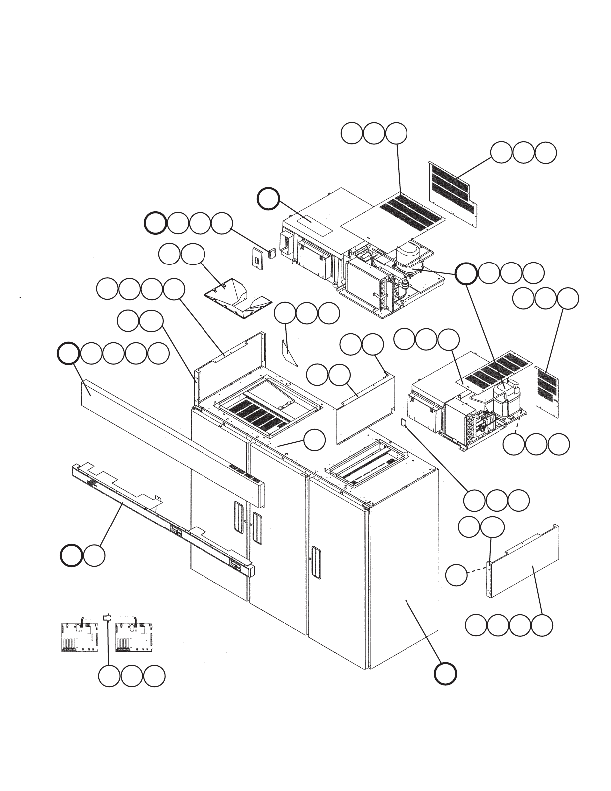
B. Refrigeration Assembly
RFH2-SSB(-HD) Refrigerator 1 Section
J-0, J-1, J-2, K-0, L-5, M-5, N-6, P-6, Q-5, R-5, S-5, S-6
1
1a 1b
J-0 to Q-5
6
1c
H
H1
K
J
J1
1d
1e
2a 2b
2
14
14a
8
2c 2d
2f 2g
2e
2h
7
22
16
22a 22b
16a
3
L
L1
13
18
13a
12
5 17
12
17a
11
19
20
9
21
4
21a
10
15
15a
Page 13

Title: B. Refrigeration Assembly Model: RFH2-SSB(-HD) Refrigerator 1 Section
Required Number
J-0
Index
No. Description
H Control Box Assembly - 2A1258A01 1 1 1 1 1
H1 Truss Head Screw 4×16, SS 7C32-0416 4 4 4 4 4
J Evaporator Fan Shroud
Assembly
J1 Truss Head Screw 4×12, SS 7C32-0412 4 4 4 4 4
K Evaporator Assembly - 2A1263A01 1 1 1 1 1
L Condenser Assembly - 3A1087A01 1 1 -
L1 T2 Screw 4×8, SS 7P32-0408 2 2 2 2 2
1 Cover-Evaporator Case - 2A0428G01 1 1 1 -
1a Draw Latch - 4A1710-01 4 4 4 4 -
1b Truss Head Screw 4×16, SS 7C32-0416 4 4 4 4 -
1c T2 Screw 4×8, SS 7P32-0408 8 8 8 8 8
1d Catch-Latch - 4A3987-01 4
1e Truss Head Screw 4×16, SS 7C32-0416 4
2 Compressor AEA9415ZXA 2A1260-01 1 1 1 1 1
2a Grommet-Compressor Mount EPDM 4A1305-01 4 4 4 4 4
2b Sleeve-Grommet 70459 4A0449-01 4 4 4 4 4
2c Hex Bolt 8×45 7B01-0845 4 4 4 4 4
2d Washer-Flat 8 7W21-0800 4 4 4 4 4
2e Split Lock Washer 8 7L21-0800 4 4 4 4 4
2f Start Capacitor
(Included in item 2: 2A1260-01)
2g Start Relay
(Included in item 2: 2A1260-01)
2h Protector
(Included in item 2: 2A1260-01)
3 Pressure Switch
(Included in 2A1257G01)
4 Drier (Included in 2A1257G01) - 4A0924-01 1 1 1 1 1
5 Thermistor-Cabinet - 4A1429-01 1 1 1 1 1
6 Filter-Condenser - 3A0277-01 1 1 1 1 1
7 Thermostat-Clean Filter 37TJ32 4A0484-01 1 1 1 1 1
Material or
Model Number Part Number
- 2A0980A01 1 1 1 1 1
3A2609A01 1 1 1
2A2726G01 1 1
4A3988-01 4
243-292MFD
110V
501-96175 3A4044-12 1 1 1 1 1
MRT22AHK-69
- 3A0335-02 1 1 -
3A4044-01 1 1 1 1 1
4A1875-02 1 1 1 1 1
4A2516-02 1 1 1
to
J-2
K-0
L-5 M-5
N-6
to
Q-5
R-5
to
S-6
8 Seal-Evaporator Tubing NP/EPDM 4A0642-01 2 2 2 2 -
4A3089-01 2
9 Fitting-Drain Overflow
(Included in 3A0381A05)
10 Washer-Drain Overflow
(Included in 3A0381A05)
Rubber Gasket
(Included in 3A0381A05)
11 Nut-Drain Fitting
(Included in 3A0381A05)
- 4A0664-01 1 -
4A2182-01 1 1 1 1
Rubber 4A0665-01 1 -
Rubber 413854-03 1 1 1 1
- 4A0666-01 1 -
13
Page 14

Title: B. Refrigeration Assembly Model: RFH2-SSB(-HD) Refrigerator 1 Section
Required Number
J-0
Index
No. Description
12 Evaporator Drain Pan
(Included in 3A0381A05)
13 Condensate Coil Strap
(Included in 3A0381A05)
13a Truss Head Screw
(Included in 3A0381A05)
14 Pressure Switch Bracket
(Included in 2A1257G01)
14a T2 Screw
(Included in 2A1257G01)
15 Drier Mount
(Included in 2A1257G01)
Drier Bracket
(Included in 2A1257G01)
15a T2 Screw
(Included in 2A1257G01)
16 Drier Bracket
(Included in 2A1257G01)
Nylon Tie
(Included in 2A1257G01)
16a T2 Screw
(Included in 2A1257G01)
17 Thermistor Bracket (A) ABS 433964-01 1 1 1 1 1
17a Truss Head Screw 4×16, SS 7C32-0416 2 2 2 2 2
18 Thermistor Bracket (B) ABS 433920-01 1 1 1 1 1
19 Coil-Condensate Coated - 4A1362G01 1 1 -
Coil-Condensate 3A1644-01 1 1 1
20 Evaporator Drain Pipe - 4A0831-01 1 1 1 1 1
21 Wire Clamp - 4A0809-01 1 1 1 1 1
21a T2 Screw 4×8, SS 7P32-0408 1 1 1 1 1
22 Compressor Base - 2A1029G02 1 -
22a Truss Head Screw 4×16, SS 7C32-0416 2 2 2 2 2
22b Truss Head Screw 5×10, SS 7C32-0510 1 1 1 1 1
Material or
Model Number Part Number
- 2A0616-01 1 -
2A0616-02 1 1 -
2A2760-01 1 1
- 3A0232-02 1 -
3A0232-03 1 1 1 1
4×12, SS 7C32-0412 1 1 1 1 1
- 4A0552-01 1 1 -
4×6 7P32-0406 1 1 -
- 4A1480-01 1 1 1 1 -
4A4282-01 1
4×8, SS 7P32-0408 2 2 2 2 2
- 4A0806-01 1 1 1 1 -
8911-0301 1
4×8, SS 7P32-0408 2 2 2 2 -
2A2756G01 1 1 1 1
to
J-2
K-0
L-5 M-5
N-6
to
Q-5
R-5
to
S-6
14
Page 15

B. Refrigeration Assembly
RFH3-SSB(-HD) Refrigerator 2 Section
J-0, J-1, J-2, K-0, L-5, M-5, N-6, P-6, Q-5, R-5, S-6
1
K
H
H1
1d
1a 1b
J1
J
1e
20
7
1c
11
19
J-0 to Q-5
4
17
2
2d
17a
2a 2b
2e
2f
18
2c
22
22a
13
13a
15
15a
6
3
10
12a
16
15
12
14
14a
8
21
9
L1
L
5
Page 16
Title: B. Refrigeration Assembly Model: RFH3-SSB(-HD) Refrigerator 2 Section
Required Number
J-0
Index
No. Description
H Control Box Assembly - 2A1300A01 1 1 1 1 1 1
H1 Truss Head Screw 4×16, SS 7C32-0416 4 4 4 4 4 4
J Evaporator Fan Shroud
Assembly
J1 Truss Head Screw 4×16 SS 7C32-0416 2 2 2 2 2 2
K Evaporator Assembly - 2A1297A01 1 1 1 1 1 1
L Condenser Assembly - 3A1138A01 1 1 1 1 1 1
L1 T2 Screw 4×8, SS 7P32-0408 4 4 4 4 4 -
Truss Head Screw 4×12 7C32-0412 2
1 Cover-Evaporator Case - 2A0245G01 1 1 1 1 1 -
1a Draw Latch - 4A1710-01 4 4 4 4 4 -
1b Truss Head Screw 4×16, SS 7C32-0416 8 4 4 4 4 -
1c T2 Screw 4×8, SS 7P32-0408 4 8 8 8 8 8
1d Catch-Latch GS 4A3987-01 4
1e Truss Head Screw 4×16, SS 7C32-0416 4
2 Compressor (For starting
components see "H. Control Box
Assembly")
2a Grommet EPDM 434403-01 4 4 4 4 4 4
2b Spacer 70459 434404-01 4 4 4 4 4 4
2c Hex Bolt 8×45 7B01-0845 4 4 4 4 4 4
2d Flat Washer 8 7W21-0800 4 4 4 4 4 4
2e Split Lock Washer 8 7L21-0800 4 4 4 4 4 4
2f Protector (Included in item 2) - 4A2069-01 1 1 1 1 1 1
3 Drier CW-052-S 4A0924-01 1 1 1 1 1 1
4 Thermistor-Cabinet 4A1429 4A1429-01 1 1 1 1 1 1
5 Filter-Condenser - 3A0277-02 1 1 1 1 1 1
Material or
Model Number Part Number
- 3A0263G01 1 1 1 1 1 1
2A2726G01 1
4A3988-01 4
AKA9427ZXA 2A1295-01 1 1 1 1 1 1
to
J-2
K-0
L-5 M-5
N-6
P-6 Q-5
R-5
S-6
6 Thermostat-Clean Filter 37TJ32 4A0484-01 1 1 1 1 1 1
7 Seal-Refrigeration Tubing NP/EPDM 4A0642-01 2 2 2 2 -
4A3089-01 2 2
8 Fitting-Drain Overflow
(Included in 4A0679A03)
9 Washer-Drain Sealing
(Included in 4A0679A03)
Rubber Gasket
(Included in 4A0679A03)
10 Evaporator Drain Pipe - 3A0143-01 1 1 1 1 1 1
11 Expansion Valve
(Included in 3A2863G01)
12 Drier Bracket - 4A0949-01 1 1 1 1 1 -
12a T2 Screw 4×8, SS 7P32-0408 2 2 2 2 2 2
PP 4A0664-01 1 1 -
4A2182-01 1 1 1 1
Rubber 4A0665-01 1 1 -
413854-03 1 1 1 1
Y1150-EFS1/8-C
4A1711-01 1 1 1 1 1 1
4A4281-01 1
16
Page 17
Title: B. Refrigeration Assembly Model: RFH3-SSB(-HD) Refrigerator 2 Section
Required Number
J-0
Index
No. Description
13 Drier Bracket - 4A0806-01 1 1 1 1 1 -
Nylon Tie 8911-0301 1
13a T2 Screw 4×8, SS 7P32-0408 2 2 2 2 2 -
14 Evaporator Drain Pan Assembly SS 4A0679A02 1 -
14a T2 Screw 4×8, SS 7P32-0408 6 6 6 6 6 5
15 Condensate Coil Strap
(Included in 4A0679A03)
15a Truss Head Screw 5×10, SS 7C32-0510 1 1 1 1 1 1
16 Pressure Switch
(Included in item L: 3A1138A01)
Pressure Switch
(Included in 4A3192G01)
17 Thermistor Bracket (A) ABS 433964-01 1 1 1 1 1 1
17a Truss Head Screw 4×16, SS 7C32-0416 2 2 2 2 2 2
18 Thermistor Bracket (B) ABS 433920-01 1 1 1 1 1 1
19 Expansion Valve Cover (A) PE 3A0372-01 1 1 1 1 1 1
20 Expansion Valve Cover (B) PE 3A0372-02 1 1 1 1 1 1
21 Coil-Condensate Coated
(Included in 3A1136G01)
Coil-Condensate
(Included in 3A1136G01)
22 Compressor Base - 2A1145G01 1 1 1 1 1 1
22a Truss Head Screw 5×10, SS 7C32-0510 2 2 2 2 2 -
Material or
Model Number Part Number
4A0679A03 1 1 1 1 1
SS 3A0413-01 1 -
3A0413-03 1 1 1 1 1
L-5 and
earlier see "L.
Condenser
Assembly"
for mounting
hardware
- 4A1421-01 1 1 1 1 -
3A0335-02 1 1
4A2516-02 1 1 1 1
2A1856-01 1 1
to
J-2
K-0
L-5 M-5
-
N-6
P-6 Q-5
R-5
S-6
17
Page 18

B. Refrigeration Assembly
RFH2-SSB(-HD), RFH3-SSB(-HD) Freezer 1 Section
J-0, J-1, J-2, K-0, L-5, M-5, N-6, P-6, Q-5, R-5, S-5, S-6
1a 1b 1c
1
J-0 to Q-5
6
12
14
13
H
14a
K
H1
J
11
1d
1e
J1
9
10
16
8
2a22b
2d 2e
7
3
15
15a
19
4
2c
2f
L
L1
21
17
18
20
20a
18
5
Page 19

Title: B. Refrigeration Assembly Model: RFH2-SSB(-HD), RFH3-SSB(-HD) Freezer 1 Section
Required Number
J-0
Index
No. Description
H Control Box Assembly
H1 Truss Head Screw 4×16,SS 7C32-0416 4 4 4 4 4 4 4
J Evaporator Fan Shroud
Assembly
J1 Truss Head Screw 4×12, SS 7C32-0412 4 4 4 4 4 4 4
K Evaporator Assembly
L Condenser Assembly
L1 T2 Screw 4×8, SS 7P32-0408 2 2 2 2 2 2 2
Material or Model
Number Part Number
-
HS-3545
(Includes
evaporator
brackets, section
"K," item 4).
-
-
-
2A1226A01 1 1 1 1 1 -
2A1226A03 1 1
2A0980A01 1 -
2A2260A01 1 -
2A2517A01 1 -
2A2517A02 1 1 1 1
2A0981A01 1 1 1 1 1 -
2A0981A06 1 1
3A0724A01 1 1 -
3A2610A01 1 1 1 -
3A2611A01 1 1
to
L-5 M-5 N-6
P-6
Q-5 R-5 S-5 S-6
1 Cover-Evaporator Case - 2A0428G01 1 1 -
2A2726G01 1 1 1 1 1
1a Draw Latch - 4A1710-01 4 4 4 4 -
4A3988-01 4 4 4
1b Truss Head Screw 4×16,SS 7C32-0416 4 4 4 4 -
1c T2 Screw 4×8, SS 7P32-0408 8 8 8 8 8 8 8
1d Catch-Latch - 4A3987-01 4 4 4
1e Truss Head Screw 4×16, SS 7C32-0416 4 4 4
2 Compressor (For starting
components see "H. Control
Box Assembly")
2a Grommet-Compressor Mount EPDM 4A1305-01 4 4 4 4 4 -
Rubber Grommet 4A1452-01 4 -
Grommet-Compressor 4A2593-01 4
2b Sleeve-Grommet - 4A0449-01 4 4 4 4 4 -
Sleeve 4A1451-01 4 -
Spacer-Compressor 4A2595-01 4
2c Hex Bolt 8×45 7B01-0845 4 4 4 4 4 -
Bolt - 4A1459-01 4 -
Hex Bolt 8×45 7B01-0845 4
2d Washer-Flat 8 7W21-0800 4 4 4 4 4 -
Washer - 4A1450-01 4 -
Flat Washer 8 7W21-0800 4
2e Split Lock Washer 8 7L21-0800 4 4 4 4 4 -
2f Protector
(Included in item 2: 4A3815-01)
3 Pressure Switch
(Included in 2A1257G01)
AJA2425ZXA 2A0937-01 1 1 1 1 1 -
SC15CLX.2 4A3815-01 1 1
- 4A1860-02 1 1 1 1 1 -
4A3679-01 1 1
- 3A0335-02 1 -
4A2516-02 1 1 1 1 1 1
19
Page 20

Title: B. Refrigeration Assembly Model: RFH2-SSB(-HD), RFH3-SSB(-HD) Freezer 1 Section
Required Number
J-0
Index
No. Description
4 Drier (Included in 2A1257G01) CW-052-S 4A0924-01 1 1 1 1 1 1 1
5 Thermistor-Cabinet Taiko 4A1429 4A1429-01 1 1 1 1 1 1 1
6 Filter-Condenser - 3A0277-01 1 1 1 1 1 1 1
7 Thermostat-Clean Filter 37TJ32 4A0484-01 1 1 1 1 1 1 1
8 Seal-Evaporator Tubing Neoprene/EPDM 4A0642-01 2 2 2 2 -
9 Fitting-Drain Overflow
(Included in 3A0381A05)
10 Washer-Drain Overflow
(Included in 3A0381A05)
Rubber Gasket
(Included in 3A0381A05)
11 Nut - Drain Fitting
(Included in item 9: 4A2182-01)
12 Gasket - Condenser Coil - 4A0455-03 1 1 1 1 1 1 1
13 Evaporator Drain Pan
(Included in 3A0381A05)
14 Condensate Coil Strap
(Included in 3A0381A05)
14a Truss Head Screw
(Included in 3A0381A05)
15 Drier Bracket
(Included in 2A1257G01)
Nylon Tie
(Included in 2A1257G01)
15a T2 Screw 4×8, SS 7P32-0408 2 2 2 2 2 2 2
16 Coil-Condensate Coated
(Included in 2A1256G02)
Coil-Condensate
(Included in 2A1256G02)
Material or Model
Number Part Number
4A3089-01 2 2 2
PP 4A0664-01 1 -
4A2182-01 1 1 1 1 1 1
- 4A0665-01 1 -
413854-03 1 1 1 1 1 1
Heyco 8463 4A0666-01 1 -
SS 2A0616-01 1 -
2A2760-01 1 1 1 1 1 1
- 3A0232-03 1 1 1 1 1 1 1
5×12, SS 7C32-0512 1 1 1 1 1 1 1
GS 4A0806-01 1 1 1 1 1 1 -
- 8911-0301 1
- 4A1362G01 1 -
- 3A1644-01 1 1 1 1 1 1
to
L-5 M-5 N-6
P-6
Q-5 R-5 S-5 S-6
17 Heater-Drain 10W 115V 4A2975-01 1 1 1 1
18 Nylon Tie CV-200 8911-0200 1 1 1 1
19 Drier Mount
(Included in 2A1257G01)
Drier Bracket
(Included in 2A1257G01)
20 Thermistor Bracket (A) ABS 433964-01 1 1 1 1 1 1 1
20a Truss Head Screw 4×16, SS 7C32-0416 2 2 2 2 2 2 2
21 Thermistor Bracket (B) ABS 433920-01 1 1 1 1 1 1 1
- 4A1480-01 1 1 1 1 1 1 -
GS 4A4282-01 1
20
Page 21

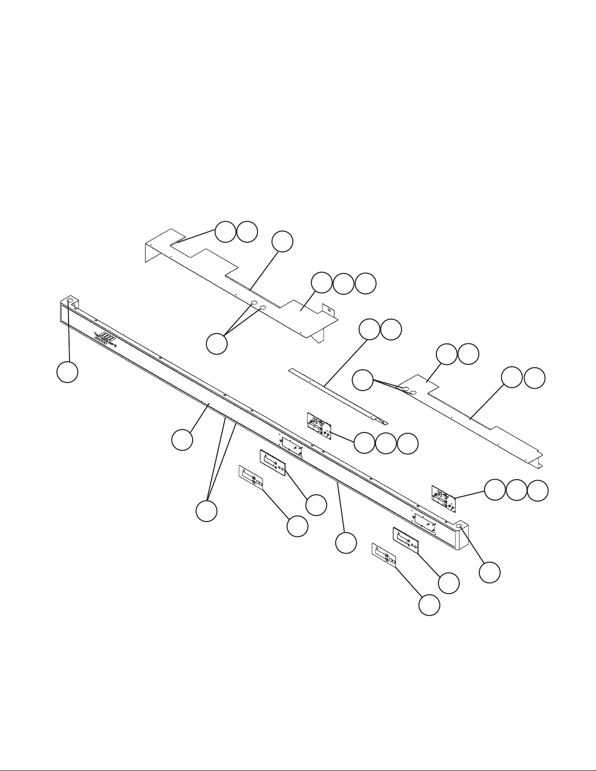
C. Control Panel Assembly
RFH2-SSB(-HD)
J-0, J-1, J-2, K-0, L-5, M-5, N-6, P-6, Q-5, R-5, S-5, S-6
14
12
6
6a
10
8a
8
2a
2
1
3
11
5
4
13
9
7a
7
2
2a
10
5
14
12
G
6
6a
21
Page 22
Title: C. Control Panel Assembly Model: RFH2-SSB(-HD)
Index
No. Description
Box-Breaker Assembly - 3A1377A01
G
Panel-Control (Painted) - 3A1198G01
1
Panel-Control 1A0835-03
Board-Display 3287A000 2A0883-01
2
Ribbon Cable
2a
Label-Display Refrigerator 4A1558-01
3
Label-Display Freezer 4A1558-02
4
Mount-Display Board PC 3A0823-01
5
Cover Wires GS 2A1033-01
6
T2 Screw 4×8, SS 7P32-0408
6a
Shield-Wire GS 4A1967-01
7
T2 Screw 4×8, SS 7P32-0408
7a
Cover-Wire Center - 4A1775-01
8
Bracket-Breaker Box GS 3A1376-01
T2 Screw 4×8, SS 7P32-0408
8a
Bushing OCB-875 428394-04
9
Locking Hole Plug - 4A0586-03
10
Locking Hole Plug - 4A0420-02
11
Grommet Strip L=30 4A1341L01
12
13
14
Material or
Model Number Part Number
1A0628G01
D-HA-104
L=48
L=340
4A1106-01
3A2850-01
3A2850-02
4A0586-02
Required Number
J-2
J-0 J-1
1 1 1 1 1 1 1
1 1 1 -
2 2 2 2 2 2 2
2 2 2 2 2 2 2
1 1 1 1 1 -
1 1 1 1 1 -
2 2 2 2 2 2 2
2 2 2 2 2 2 2
8 8 8 8 8 8 8
1 -
1 -
2 2 2 2 2 2 -
K-0 L-5 M-5
1 -
1 1 1 1 1 1
2 2 2 2 2 2
1 1 1 1 1 1
7 7 7 7 7 7
1 1 1 1 1 1
2 2 2 2 2
2 2 2 2 2 2
6 6 6 6 6 6
2 2 2 2 2 2
N-6
P-6
1 1 1
1 1
1 1
Q-5
to
S-6
2
22
Page 23
C. Control Panel Assembly
RFH3-SSB(-HD)
J-0, J-1, J-2, K-0, L-5, M-5, N-6, P-6, Q-5, R-5, S-6
15
14
10
13
6
6a
12
8a
8
7a
7
10
11
2a
12
16
10
1
9
5
3
9
2a
2
16
2
10
5
4
23
Page 24

Title: C. Control Panel Assembly Model: RFH3-SSB(-HD)
Index
No. Description
Panel-Control (Painted) - 2A1409G01
1
Panel-Control SS 1A0836-03
Board-Display 3287A000 2A0883-01
2
Nylon Screw - 4A1397-01
2a
Label-Display Refrigerator 4A1558-01
3
Label-Display Freezer 4A1558-02
4
Mount-Display Board PC 3A0823-01
5
Control Panel Cover GS 3A0599-01
6
T2 Screw 4×8, SS 7P32-0408
6a
Cover-Wires GS 2A1414-01
7
T2 Screw 4×8, SS 7P32-0408
7a
Board Cover GS 3A1046-01
8
T2 Screw 4×8, SS 7P32-0408
8a
Locking Plug Hole - 4A0420-02
9
Locking Plug Hole - 4A0586-03
10
Grommet Strip L=58 4A1341L01
11
12
13
14
15
Ribbon Cable D-HA-104 4A1106-02
16
Material or
Model Number Part Number
1A0629G01
3A2850-01
3A2850-02
2A1572-01
4A0586-02
L=329
L=68
L=104
L=79
Required Number
J-0
J-1 J-2 K-0 L-5
1 1 1 -
2 2 2 2 2 2
8 8 8 8 8 8
1 1 1 1 -
1 1 1 1 -
2 2 2 2 2 2
1 -
1 1 1 1 1
2 4 4 4 4 4
1 1 1 1 1 1
4 4 4 4 4 4
1 1 1 1 1 1
2 2 2 2 2 2
3 3 3 3 3 -
6 6 6 6
2 2 2 2 2 2
2 2 2 2 2 2
2 2 2 2 2 2
2 2 2 2 2 2
1 1 1 1 1 1
2 2 2 2 2 2
M-5
N-6
1 -
1 1
1 1
1 1
P-6
to
S-6
3
24
Page 25
D. Body-Final
RFH2-SSB
J-0, J-1, J-2, K-0, L-5, M-5, N-6, P-6, Q-5, R-5, S-5, S-6
M
15
13a
13
P
6
3
N
6
2
1
4
10a
10
8
25
8a
14
4
14a
1
9a
9
11a
11
12a
12
7
7a
5a5
Page 26
Title: D. Body-Final Model: RFH2-SSB
J-0
Index
No. Description
M Body-Prenal - 2A1359A01 1 1 1 1
N Door-Right SS 1A0318A01 1 1 -
P Door-Left SS 1A0318A02 1 1 -
1 Hinge-Stop Pin SS 4A0444-01 2 -
2 Hinge-Tension Screw SS 4A0446-01 2 2 2 2
3 Hinge-Bushing Cover SS 4A0445-01 2 2 2 2
4 Hinge-Lock Washer SS 4A0553-01 2 2 2 2
5 Hinge-Pivot Pin (BTM) SS 4A0443-01 2 -
5a Hinge-Lock Washer SS 4A0553-01 2 -
6 Hinge-Pivot Pin (Top) SS 4A0442-01 2 -
7 Bracket-Door Hinge (UL,LR) Use latest for
Bracket-Door Hinge (LR) 3A1626-01 1 1 1
7a Countersunk Screw (Included
in 2A0693G02)
8 Bracket-Door Hinge (LL,UR) Use latest for
Bracket-Door Hinge (UR) 3A1580-01 1 1 1
8a Countersunk Screw (Included
in 2A0693G02)
9 Hinge-Stop Plate (L) SS 4A0441-02 1 1 1 1
9a Screw-Stop Plate SS 4A0483-01 1 1 1 1
10 Bracket-Door Hinge (UL) SS 3A1581-01 1 1 1
10a Countersunk Screw (Included
in 2A0693G02)
11 Bracket-Door Hinge (LL) - 3A1627-01 1 1 1
11a Countersunk Screw (Included
in 2A0693G02)
12 Hinge-Stop Plate (R) SS 4A0441-01 1 1 1 1
12a Screw-Stop Plate SS 4A0483-01 1 1 1 1
13 Plate-Strike (Front) SS 4A0355-01 1 1 1 1
13a Truss Head Screw 4×6, SS 7P32-0408 1 1 -
14 Plate-Strike (Base) SS 4A0354-01 1 1 1 1
14a T2 Screw 4×8, SS 7P32-0408 2 2 2 2
15 T2 Screw 4×8, SS 7P32-0408 4 -
Canoe Clip SS 4A0629-01 4 4 T2 Screw 4×8 7P32-0408 4
Material or
Model Number Part Number
1A0318A03 1 1
1A0318A04 1 1
4A2180-01 2 2 2
4A2179-01 2 2 2
3A0209-01 2 -
all aux. codes
5×20, SS 7C42-0520 6 3 3 3
3A0215-01 2 -
all aux. codes
5×20, SS 7C42-0520 6 3 3 3
5×20, SS 7C42-0520 3 3 3
5×20, SS 7C42-0520 3 3 3
4×8, SS 7C32-0408 1 1
to
J-2
K-0
L-5
M-5
to
R-5
Required Number
S-5
S-6
26
Page 27

D. Body-Final
RFH2-SSB-HD
J-0, J-1, J-2, K-0, L-5, M-5, N-6, P-6, Q-5, R-5, S-6
M
S
Q
U
3
T
R
6
4
15
15a
1
10a
10
12
6
4
1
12a
8
5
9a
8a
5a
12a
9
7
11
7a
2
12
10
9a
10a
13
4
14
9
15
15a
13
4
14
27
Page 28

Title: D. Body-Final Model: RFH2-SSB-HD
J-0
Index
No. Description
M Body-Prefinal SS 2A1417A01 1 1 1
Q Door-Half (UR) SS 1A0326A01 1 1 -
R Door-Half (LR) SS 1A0324A01 1 1 -
S Door-Half (UL) SS 1A0324A02 1 1 -
T Door-Half (LL) SS 1A0326A02 1 1 -
U Mullion-Horizontal Non-Heated 2A1323A01 2 1 1
1 Hinge-Stop Pin SS 4A0444-01 2 -
2 Hinge-Tension Screw SS 4A0446-01 4 4 4
3 Hinge-Bushing Cover SS 4A0445-01 4 4 4
4 Hinge-Lock Washer SS 4A0553-01 4 4 4
5 Hinge-Pivot Pin (BTM) SS 4A0443-01 2 -
5a Hinge-Lock Washer SS 4A0553-01 2 -
6 Hinge-Pivot Pin (Top) SS 4A0442-01 2 -
7 Bracket-Door Hinge (UL,LR) Use latest for
Bracket-Door Hinge (LR) 3A1626-01 1 1
7a Countersunk Screw (Included
in 2A1345G02)
8 Bracket-Door Hinge (LL,UR) Use latest for
Bracket-Door Hinge (LL) 3A1627-01 1 1
8a Countersunk Screw (Included
in 2A1345G02)
9 Hinge-Stop Plate (R) SS 4A0441-01 2 2 2
9a Screw-Stop Plate SS 4A0483-01 2 2 2
10 Bracket-Door Hinge (UR) SS 3A1580-01 2 2
10a Countersunk Screw (Included
in 2A1345G02)
11 Cover-Corner ABS 3A0221-01 16 -
12 Hinge-Stop Plate (L) SS 4A0441-02 2 2 2
12a Screw-Stop Plate SS 4A0483-01 2 2 2
13 Stop Pin SS 4A1734-01 2 2 2
14 Pivot Pin SS 4A1735-01 2 2 2
15 Bracket-Door Hinge (UL) SS 3A1581-01 2 2
15a Countersunk Screw (Included
in 2A1345G02)
Material or
Model Number Part Number
1A0326A03 1
1A0324A03 1
1A0324A04 1
1A0326A04 1
Heated
(Freezer only)
all aux. codes
5×20, SS 7C42-0520 9 3 3
all aux. codes
5×20, SS 7C42-0520 9 3 3
5×20, SS 7C42-0520 6 6
5×20, SS 7C42-0520 6 6
2A1323A04 1 1
4A2180-01 2 2
4A2179-01 2 2
3A0209-01 3 -
3A0215-01 3 -
3A1751-01 8 8
to
J-2
K-0
L-5
Required Number
M-5
to
S-6
28
Page 29

D. Body-Final
RFH3-SSB
J-0, J-1, J-2, K-0, L-5, M-5, N-6, P-6, Q-5, R-5, S-6
M
11
V
P
N
13
14
13a
14a
3
16
11
12a
6
15
4
6
15a
4
1
10a
10
2
12
9
1
8
8a
5
5a
9a
7
7a
29
Page 30

Title: D. Body-Final Model: RFH3-SSB
J-0
Index
No. Description
M Body-Prefinal - 1A0390A01 1 1 1 1
N Door-Right SS 1A0318A01 2 2 - -
P Door-Left SS 1A0318A02 1 1 - -
V Mullion-Vertical SS 2A1289A01 1 1 1 1
1 Hinge-Stop Pin SS 4A0444-01 3 -
2 Hinge-Tension Screw SS 4A0446-01 3 3 3 3
3 Hinge-Bushing Cover SS 4A0445-01 3 3 3 3
4 Hinge-Lock Washer SS 4A0553-01 4 3 3 3
5 Hinge-Pivot Pin (BTM) SS 4A0443-01 3 -
5a Hinge-Lock Washer SS 4A0553-01 2 -
6 Hinge-Pivot Pin (Top) SS 4A0442-01 3 -
7 Bracket-Door Hinge (UL,LR) Use latest for
Bracket-Door Hinge (LR) 3A1626-01 2 2 2
7a Countersunk Screw (Included
in 2A1085G02)
8 Bracket-Door Hinge (LL,UR) Use latest for
Bracket-Door Hinge (LL) 3A1627-01 1 1 1
8a Countersunk Screw (Included
in 2A1085G02)
9 Hinge-Stop Plate (R) SS 4A0441-01 2 2 2 2
9a Screw-Stop Plate SS 4A0483-01 2 2 2 2
10 Bracket-Door Hinge (UR) SS 3A1580-01 2 2 2
10a Countersunk Screw (Included
in 2A1085G02)
11 Cover-Corner ABS 3A0221-01 12 -
12 Hinge-Stop Plate (L) SS 4A0441-02 1 1 1 1
12a Screw-Stop Plate SS 4A0483-01 1 1 1 1
13 Plate-Strike (Base) SS 4A0354-01 1 1 1 1
13a T2 Screw 4×8, SS 7P32-0408 2 2 2 2
14 Plate-Strike (Front) SS 4A0355-01 1 1 1 1
Truss Head Screw 4×8, SS 7C32-0408
14a
15 Bracket-Door Hinge (UL) SS 3A1581-01 1 1 1
15a Countersunk Screw (Included
in 2A1085G02)
16 T2 Screw 4×8, SS 7P32-0408 4 -
Canoe Clip SS 4A0629-01
T2 Screw 4×8, SS 7P32-0408
Material or
Model Number Part Number
1A0318A03 2 2
1A0318A04 1 1
4A2180-01 3 3 3
4A2179-01 3 3 3
3A0209-01 3 -
all aux. codes
5×20, SS 7C42-0520 9 6 6 6
3A0215-01 3 -
all aux. codes
5×20, SS 7C42-0520 9 3 3 3
5×20, SS 7C42-0520 6 6 6
3A1751-01 4 4 4
5×20, SS 7C42-0520 3 3 3
to
J-2
1 1 1 1
M-5
K-0
to
L-5
R-5
4 4 -
Required Number
S-5
S-6
4
30
Page 31

D. Body-Final
RFH3-SSB-HD
J-0, J-1, J-2, K-0, L-5, M-5, N-6, P-6, Q-5, S-6
W
M
S
Q
11
U
3
2
12a
9a
12a
9a
9
T
R
1
6
4
6
4
1
8
9
12
8a
12
13
10
10a
15
15a
13
15
15a
10
10a
31
4
14
7a
5
5a
7
14
Page 32

Title: D. Body-Final Model: RFH3-SSB-HD
Required Number
Index
No. Description
M Body-Prefinal - 2A1439A01 1 1 1 1 1
Q Door-Half (UR) - 1A0326A01 2 2 2 2 -
R Door-Half (LR) - 1A0324A01 2 2 2 2 -
S Door-Half (UL) - 1A0324A02 1 1 1 1 -
T Door-Half (LL) - 1A0326A02 1 1 1 1 -
U Mullion-Horizontal Non-Heated 2A1323A01 1 1 1 -
W Mullion-Cross - 2A1350A01 1 1 1 1 1
1 Hinge-Stop Pin SS 4A0444-01 3 3 -
2 Hinge-Tension Screw SS 4A0446-01 6 6 6 6 6
3 Hinge-Bushing Cover SS 4A0445-01 6 6 6 6 6
4 Hinge-Lock Washer SS 4A0553-01 6 6 6 6 6
5 Hinge-Pivot Pin (BTM) SS 4A0443-01 3 3 3 -
5a Hinge-Lock Washer SS 4A0553-01 6 6 6 -
6 Hinge-Pivot Pin (Top) SS 4A0442-01 3 3 3 -
7 Bracket-Door Hinge (UL, LR) Use latest for
Bracket-Door Hinge (LR) 3A1626-01 2 2
7a Countersunk Screw (Included
in 2A1397G02)
8 Bracket-Door Hinge (LL, UR) Use latest for
Bracket-Door Hinge (LL) 3A1627-01 1 1
8a Countersunk Screw (Included
in 2A1397G02)
9 Hinge-Stop Plate (R) SS 4A0441-01 4 4 4 4 4
9a Screw-Stop Plate SS 4A0483-01 4 4 4 4 4
10 Bracket-Door Hinge (UR) - 3A1580-01 3 3
10a Countersunk Screw (Included
in 2A1397G02)
11 Cover-Corner ABS 3A0221-01 24 24 24 -
12 Hinge-Stop Plate (L) SS 4A0441-02 2 2 2 2 2
12a Screw-Stop Plate SS 4A0483-01 2 2 2 2 2
13 Stop Pin SS 4A1734-01 3 3 3 3 3
14 Pivot Pin SS 4A1735-01 3 3 3 3 3
15 Bracket-Door Hinge (UL) - 3A1581-01 3 3
15a Countersunk Screw (Included
in 2A1397G02)
Material or
Model Number Part Number
1A0326A03 2
1A0324A03 2
1A0324A04 1
1A0326A04 1
Heated 2A1323A04 1 1
4A2180-01 3 3 3
4A2179-01 3 3
3A0209-01 5 5 5 -
all aux. codes
5×20, SS 7C42-0520 15 15 15 6 6
3A0215-01 4 4 4 -
all aux. codes
5×20, SS 7C42-0520 12 12 12 3 3
5×20, SS 7C42-0520 9 9
3A1751-01 16 16
5×20, SS 7C42-0520 9 9
J-1
J-0
J-2 K-0 L-5
M-5
to
S-6
32
Page 33

E. Panel-Front Hinged Assembly
RFH2-SSB(-HD), RFH3-SSB(-HD)
J-0, J-1, J-2, K-0, L-5, M-5, N-6, P-6, Q-5, R-5, S-5, S-6
2
3
1
3a
3
3a
4
Title: E. Panel-Front Hinged Assembly Model: RFH2-SSB(-HD), RFH3-SSB(-HD)
J-0
L-5
Index
No. Description
1 Hinge-Front Panel (L) GS 4A2153-01 1
2 Hinge-Front Panel (R) GS 4A2154-01 1
3 Channel-Hinge GS 4A2170-01 2
3a Truss Head Screw 5×8, SS 7C32-0508 4
4 Panel-Front
Material or
Model Number Part Number
RFH2-SSB(-HD)
SS
RFH3-SSB(-HD)
SS
1A0040-01 1 -
1A0624-02 1
1A0286-01 1 -
1A0624-03 1
to
K-0
to
S-6
Required Number
33
Page 34

F. Label Location
RFH2-SSB(-HD)
J-0, J-1, J-2, K-0, L-5, M-5, N-6, P-6, Q-5, R-5, S-5, S-6
3
12
2
1
11
9
7
8
13
6
8
3
9
10
5
4
34
Page 35

Title: F. Label Location Model: RFH2-SSB(-HD)
Required Number
J-1
Index
No. Description
1 Label-Penguin-HA (L) - 4A0526-02 1 1 1 1 1 1
2 Emblem-Hoshizaki - 4A0560-01 1 1 1 1 1 1
3 Condensate Heater Label - 4A1039-01 2 2 2 2 2 2
4 Caution Label PVC FILM 4A1931-01 1 1 1 1 1
5 Wiring Label Junction/
6 Wiring Label Refrigerator 2A1286-01 1 1 -
7 Wiring Label Freezer 2A1270-01 1 1 -
8 Label-R404A - 4A0960-01 2 2 2 2 2 2
9 Label-On/Off - 4A0522-01 2 2 2 2 2 2
10 Label-Display Info Label-
11 Cover-Nameplate - 4A3727-01 1 1 1 1
12 Tag-Warning: Electrical
Connection
13 Nameplate
Material or
Model Number Part Number
3A1210-01 1 1 -
Breaker Box
Refrigerator
Label-Freezer 3A0592-01 1 -
Label-Display 3A1413-01 1 1 1 1 1
- 4A1793-01 1 1 1 1 1 1
RFH2-SSB
RFH2-SSB-HD
3A2114-01 1 1 1 1
2A2346-01 1 1 1 1
2A2341-01 1 1 1 -
2A4241-01 1
3A1062-01 1 -
4A1798-01 1 -
3A1447-01 1 1 -
1A0764-01 1 1 1
4A1834-01 1 -
3A1448-01 1 1 -
1A0764-02 1 1 1
J-0
to
L-5 M-5
N-6
P-6
Q-5
to
S-5 S-6
35
Page 36

F. Label Location
RFH3-SSB(-HD)
J-0, J-1, J-2, K-0, L-5, M-5, N-6, P-6, Q-5, R-5, S-6
3
2
6
5
12
7
8
9
4
9
3
10
1
11
13
8
36
Page 37

Title: F. Label Location Model: RFH3-SSB(-HD)
Required Number
J-1
Index
No. Description
1 Label-Penguin-HA (L) - 4A0526-02 1 1 1 1 1 1
2 Emblem-Hoshizaki - 4A0560-01 1 1 1 1 1 1
3 Condensate Heater Label - 4A1039-01 2 2 2 2 2 2
4 Caution Label PVC FILM 4A1931-01 1 1 1 1 1 1
5 Wiring Label Junction/
6 Wiring Label Refrigerator 2A1999-01 1 1 -
7 Wiring Label Freezer 2A1270-01 1 1 -
8 Label-R404A - 4A0960-01 2 2 2 2 2 2
9 Label-On/Off - 4A0522-01 2 2 2 2 2 2
10 Label-Display Info Label-
11 Cover-Nameplate - 4A3727-01 1 1 1 1
12 Tag-Warning: Electrical
Connection
13 Nameplate
Material or
Model Number Part Number
3A1210-01 1 1 -
Breaker Box
Refrigerator
Label-Freezer 3A0592-01 1 -
Label-Display 3A1413-01 1 1 1 1 1
- 4A1793-01 1 1 1 1 1 1
RFH3-SSB
RFH3-SSB-HD
3A2114-01 1 1 1 1
2A2349-01 1 1 1 1
2A2341-01 1 1 1 -
2A4241-01 1
3A1062-01 1 -
4A1811-01 1 -
3A1449-01 1 1 -
1A0764-03 1 1 1
4A1837-01 1 -
3A1450-01 1 1 -
1A0764-04 1 1 1
J-0
to
L-5 M-5
N-6
P-6
Q-5
R-5 S-6
37
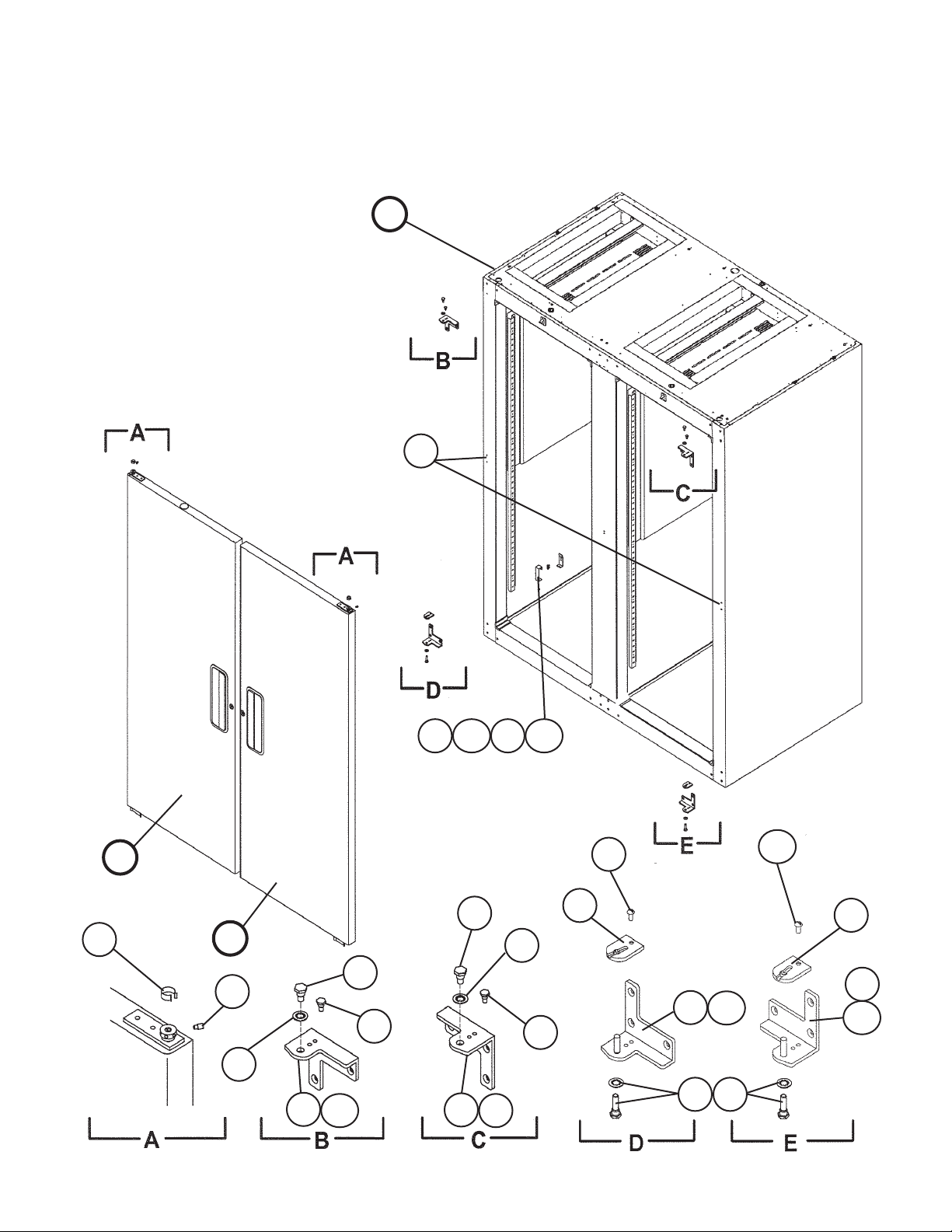
Page 38

G. Breaker Box Assembly
RFH2-SSB(-HD), RFH3-SSB-(HD)
J-0, J-1, J-2, K-0, L-5, M-5, N-6, P-6, Q-5, R-5, S-5, S-6
1
2
Title: G. Breaker Box Assembly Model: RFH2-SSB(-HD), RFH3-SSB(-HD)
J-0
Index
No. Description
1 Box-Breaker Q02l30S SQ-D 3A1375-01 1
2 Circuit-Breaker 30 AMP
3 Bushing OCB-875 428394-04 1
Material or
Model Number Part Number
4A1932-01
Q0130 SQ-SD
to
S-6
1
38
3
Required Number
Page 39

H. Control Box Assembly
RFH2-SSB(-HD) Refrigerator 1 Section
J-0, J-1, J-2, K-0, L-5, M-5, N-6, P-6, Q-5, R-5, S-5, S-6
X
4
3
Title: H. Control Box Assembly Model: RFH2-SSB(-HD) Refrigerator 1 Section
J-0
Index
No. Description
X Common Control Box HS-3500 2A1147A01 1
1 Plug Housing (3 Pin) 3191-03P 412832-06 1
2 Receptacle Housing (3 Pin) 3191-03R1 412831-06 1
3 Bushing SB-1500-21 420470-06 1
4 Grounding Screw M5 433304-02 1
Material or
Model Number Part Number
to
S-6
2
1
Required Number
39
Page 40

H. Control Box Assembly
RFH3-SSB(-HD) Refrigerator 2 Section
J-0, J-1, J-2, K-0, L-5, M-5, N-6, P-6, Q-5, R-5, S-6
4a
4
1
2a
2
X
3
Title: H. Control Box Assembly Model: RFH3-SSB(-HD) Refrigerator 2 Section
J-0
Index
No. Description
X Common Control Box - 2A1147A01 1
1 Capacitor-Start 161-193 MFD,
2 Relay-Start GE 3ARR2-
2a T2 Screw 4×8, SS 7P32-0408 1
3 Grounding Screw M5 433304-02 1
4 Strap GS 434580-01 1
4a T2 Screw 4×8, SS 7P32-0408 1
Material or
Model Number Part Number
3A1142-01 1
165V
4A1709-01 1
KCP181S
to
S-6
Required Number
40
Page 41

H. Control Box Assembly
RFH2-SSB(-HD), RFH3-SSB(-HD) Freezer 1 Section
J-0, J-1, J-2, K-0, L-5, M-5, N-6, P-6, Q-5, R-5, S-5, S-6
X
7
6
Item 1 not shown
1
2
4
5
5a
8
3
3a
11
41
10
9a
9
Page 42

Title: H. Control Box Assembly Model: RFH2-SSB(-HD), RFH3-SSB(-HD) Freezer1 Section
Required Number
J-0
M-5
Q-5
Index
No. Description
X Common Control Box - 2A1147A01 1 1 1 1
1 Capacitor-Run 15MFD, 370V 439943-04 1 -
2 Capacitor-Start 270-324MFD,
3 Starter - 4A1107-03 1 1 1 -
3a T2 Screw 4×8, SS 7P32-0408 1 1 1 2
4 Grounding Screw M5 433304-02 1 1 1 1
5 Strap GS 434580-14 1 1 1 -
5a T2 Screw 4×8, SS 7P32-0408 1 1 1 1
6 Plug Housing (3 Pin) 3191-03P 412832-06 1 1 1 1
7 Receptacle Housing (3 Pin) 3191-03R1 412831-06 1 1 1 1
8 Bushing SB-1500-21 420470-06 1 1 1 1
9 Mount Bracket GS 4A1876-01 1 1 1 -
9a T2 Screw 48, SS 7P32-0408 2 2
10 Fuse Holder HTB92I 4A0892-01 1 1
11 Fuse AGC-5 5A
Material or
Model Number Part Number
3A2005-08 1 1 -
3A0076-06 1 1 1 -
165V
410MFD, 150V 4A2134-02 1
4A3683-01 1
434580-15 1
4A3363-01 1
4A0893-09 1 1
250V
to
L-5
to
P-6
to
S-5 S-6
42
Page 43

J. Evaporator Fan Shroud Assembly
RFH2-SSB(-HD) Refrigerator 1 Section
J-0, J-1, J-2, K-0, L-5, M-5
2c
HS-3541
See next page for information about noninterchangeable part change.
1a
1
2a
4
3a
3
3b 3c
2
2b
5
J. Evaporator Fan Shroud Assembly
RFH2-SSB(-HD) Refrigerator 1 Section
N-6, P-6, Q-5, R-5, S-5, S-6
HS1
HS4
HS1a
HS1b
HS3
HS3a
HS2
HS3b
HS2a
HS3c
HS2b
HS5
1
4
3a
3
3b 3c
43
2a
2
5
2b
Page 44

Title: J. Evaporator Fan Shroud Assembly Model: RFH2-SSB(-HD) Refrigerator 1 Section
Required Number
J-0
Index
No. Description
1 Shroud-Evaporator - 2A0846-01
2 Bracket-Fan Motor - 3A2501-01 2
2a Truss Head Screw 5×12, SS 7C32-0512 2
2b Lock Washer - 4A0459-01
3 Fan Motor-Evaporator SHINKO 4A2563-01 1
3a Truss Head Screw 4×40, SS 7C32-0440 4
3b Split Lock Washer 4, SS 7L22-0400 4
3c Hex Nut 4, SS 7N12-0400 4
4 Blade-Evaporator Fan - 4A2378-01 1
5 Wire Tie (Twist) - 4A1223-01 1
Material or
Model Number Part Number
M-5
Note: Parts are not interchangeable. For
serial numbers M-5 and earlier, see the
to
information below. For serial numbers N-6
and later, order the appropriate parts from
this chart.
N-6
to
S-6
1
2
Note for Models Having Serial Number M5 and Earlier
If your model falls into this time frame and you need to replace parts in the assembly,
review the scenarios below and follow the appropriate solution.
a. Unit's evaporator shroud has only two holes or has four holes but only the lower two
holes are threaded.
Solution: Order HS-3541 that contains a motor (Shinko), brackets, blade,
and all fasteners required for mounting to the shroud using the
existing threaded holes.
b. Unit's evaporator shroud has four threaded holes and a Jakel motor.
Solution: Order a new motor (Shinko), brackets, fan blade, and all fasteners
listed in the parts list above. Attach the brackets to the upper two
holes on the shroud.
HS-3541-Shinko Fan Motor Conversion
Index
No. Description
HS1 Bracket-Fan Motor (L) - 3A2357-01 1
HS1a Truss Head Screw 5×12, SS 7C32-0512 1
HS1b Lock Washer - 4A0459-01 1
HS2 Bracket-Fan Motor (R) - 3A2358-01 1
HS2a Truss Head Screw 5×12, SS 7C32-0512 1
HS2b Lock Washer - 4A0459-01 1
HS3 Fan Motor-Evaporator Shinko 4A2563-01 1
HS3a Truss Head Screw 4×40, SS 7C32-0440 4
HS3b Split Lock Washer M4, SS 7L22-0400 4
HS3c Hex Nut M4, SS 7N12-0400 4
HS4 Blade-Evaporator Fan - 4A2378-01 4
HS5 Wire Tie (Twist) - 4A1223-01 2
Material or
Model Number Part Number
M-5 and earlier
Required Number
44
Page 45

J. Evaporator Fan Shroud Assembly
RFH3-SSB(-HD) Refrigerator 2 Section
J-0, J-1, J-2, K-0, L-5, M-5, N-6, P-6, Q-5, R-5, S-6
3
1a
1
4a
4
8
1b
2
7
5
6
Title: J. Evaporator Fan Shroud Assembly Model: RFH3-SSB(-HD) Refrigerator 2 Section
Required Number
J-0
L-5
Index
No. Description
1 Blade-Fan Pusher
1a Hex Nut - 4A1345-01 1 1 1 1
1b Lock Washer - 4A0459-01 3 3 3
2 Evaporator Fan Assembly
3 Motor-Evaporator Fan (Included
in item 2: 4A0411-01)
4 Orifice-Evaporator Fan
(Included in item 2: 4A0411-01)
4a T2 Screw 4×8, SS 7P32-0408 3 3 3 3
5 Gasket L=502 4A0414L01 1 -
6 Shroud-Evaporator SS 1A0100-01 1 1 1 -
7 Wire Tie (Twist) - 4A1223-01 2 2
8 Nylon Tie CV-100 8911-0100 2 2
Material or
Model Number Part Number
AD9CCW30UBA
-
PSC4BE9BEA1
SS 4A0412-01 1 1 1 1
3A0438-01 1 1 1 1
4A0411-01 1 1 1 1
4A0413-01 1 1 1 1
4A0414L03 1 1 1
1A1274-01 1
to
K-0
to
N-6
P-6
Q-5
R-5
S-6
45
Page 46

J. Evaporator Fan Shroud Assembly
RFH2-SSB(-HD), RFH3-SSB(-HD) Freezer 1 Section
J-0, J-1, J-2, K-0, L-5, M-5
3
2a 2b 2c
2
5
1
4
4a
4b
J. Evaporator Fan Shroud Assembly
RFH2-SSB(-HD), RFH3-SSB(-HD) Freezer 1 Section
N-6, P-6, Q-5, R-5, S-5, S-6
1
4
4a
4b
2a 2b 2c
2
6
5
3
46
Page 47

Title: J. Evaporator Fan Shroud Assembly Model: RFH2-SSB(-HD), RFH3-SSB(-HD) Freezer 1 Section
Required Number
J-0
Index
No. Description
1 Shroud-Evaporator Fan - 2A2565G01
2 Motor-Evaporator Fan
2a Hex Nut
2b Split Lock Washer
2c Truss Head Screw
3 Blade-Fan
4 Bracket-Fan Motor
4a Lock Washer - 4A0459-01 2 2
4b Truss Head Screw 5×12, SS 7C32-0512 2 2
5 Wire Tie (Twist) - 4A1223-01 2 2
6 Bushing SB-625-8 420470-01 1 1
Material or
Model Number Part Number
2A2565G02 1
PSC4BE9BEA1
M4, SS
M4, SS
4×40, SS 7C32-0440 4 4
-
-
4A2563-01 1 1
7N12-0400 4 4
7L22-0400 4 4
4A2802-01 1 1
3A2480-01 2 2
to
M-5 N-6
Note: Parts are not interchangeable. For serial numbers M-5
and earlier, see the information below. For serial numbers N-6
and later, order the appropriate parts from this chart.
P-6
to
S-6
1 -
Note for Models Having Serial Number M5 and Earlier
If your model falls into this time frame and you need to replace parts in the assembly,
use the information below.
Solution: Order HS-3545 which contains the current fan-evaporator
assembly (2A2517A02), evaporator brackets and all fasteners
required for mounting to the evaporator assembly.
HS-3545
Index
No. Description
HS1 Fan-Evaporator Assembly - 2A2517G02 1
HS2 Bracket-Evaporator - 4A2542-01 2
HS2a Truss Head Screw 4×12, SS 7C32-0412 4
HS2b T2 Screw 4×8, SS 7P32-0408 4
Material or
Model Number Part Number
M-5 and earlier
Required Number
47
Page 48

K. Evaporator Assembly
RFH2-SSB(-HD) Refrigerator 1 Section
J-0, J-1, J-2, K-0, L-5, M-5, N-6, P-6, Q-5, R-5, S-5, S-6
2a
2
2a
2
1
3
4
10
9
5
6
8
Title: K. Evaporator Assembly Model: RFH2-SSB(-HD) Refrigerator 1 Section
J-0
N-6
Index
No. Description
1 Evaporator 03EZ0603K-
2 Bracket-Evaporator SS 4A1588-01 2 -
2a T2 Screw 4×8, SS 7P32-0408 4 4
3 Thermistor Clip - 320418-01 1 1
4 Thermistor-Defrost 4A1428 4A1428-01 1 1
5 Expansion Valve Y1150-EFS-
6 Expansion Valve Cover (A) PE 3A0372-01 1 1
7 Expansion Valve Cover (B) PE 3A0372-02 1 1
8 Tube - Liquid - 4A1332-01 1 1
9 Tube - Evaporator Inlet - 4A1292-01 1 1
10 Insulation Tubing L=350 7762-1020 1 1
Material or
Model Number Part Number
2A1262-01 1 1
8×19
4A2542-01 2
4A1594-01 1 1
1/8-C
to
M-5
to
S-6
7
Required Number
48
Page 49

K. Evaporator Assembly
RFH3-SSB(-HD) Refrigerator 2 Section
J-0, J-1, J-2, K-0, L-5, M-5, N-6, P-6, Q-5, R-5, S-6
3
3a
1
2
2a
54
Title: K. Evaporator Assembly Model: RFH3-SSB(-HD) Refrigerator 2 Section
J-0
Index
No. Description
Evaporator 602899 2A1382-01
1
Bracket-Evaporator Shroud (R) SS 4A0545-01
2
T2 Screw 4×8, SS 7P32-0408
2a
Bracket-Evaporator Shroud (L) SS 4A0548-01
3
Material or
Model Number Part Number
to
S-6
1
1
2
1
Required Number
T2 Screw 4×8, SS 7P32-0408
3a
Thermistor Clip - 320418-01
4
Thermistor-Defrost 4A1428 4A1428-01
5
2
1
1
49
Page 50

K. Evaporator Assembly
RFH2-SSB(-HD), RFH3-SSB(-HD) Freezer 1 Section
J-0, J-1, J-2, K-0, L-5, M-5, N-6, P-6, Q-5, R-5, S-5, S-6
16
13
4
4a
1
7
9
11
5
6
12
14
17
8
3a
3
15
10
2
50
Page 51

Title: K. Evaporator Assembly Model: RFH2-SSB(-HD), RFH3-SSB(-HD) Freezer 1 Section
Required Number
J-0
L-5
P-6
Index
No. Description
1 Evaporator - 2A0781-01 1 1 1 1
2 Heater-Defrost - 3A0846-01 1 1 1 1
3 Thermostat-Defrost Therm-O-Disc 4A0954-01 1 -
3a T2 Screw 4×8,SS 7P32-0408 2 2 2 2
4 Bracket-Evaporator SS 4A1588-01 2 2 -
4a T2 Screw 4×8,SS 7P32-0408 4 4 4 4
5 Thermistor-Clip - 320418-01 1 1 1 1
6 Thermistor-Defrost Taiko 4A1428-01 1 1 1 1
7 Expansion Valve Y1150-EFS-
8 Expansion Valve Cover (A) PE 3A0372-01 1 1 1 1
9 Expansion Valve Cover (B) PE 3A0372-02 1 1 1 1
10 Bushing OCB-500 428394-02 1 1 1 1
11 Tube-Liquid - 4A1332-01 1 1 1 1
12 Tube-Evaporator Inlet - 4A1292-01 1 1 1 1
13 Insulation-Tubing L=655 7762-1030 1 1 1 1
14 Insulation-Tubing L=365 7762-1030 1 1 1 1
15 Support-Heater Defrost - 4A2506-01 3 3 3 3
16 Gasket-PVC L=206 4A0414L03 2 2 2 2
17 Cork Insulation Tape L=80 8216-BK20 1 1 1 1
Material or
Model Number Part Number
4A0954-02 1 1 1
4A2542-01 2 2
4A1594-01 1 1 1 -
1/8-Z
- 4A4196-01 1
to
K-0
to
N-6
to
R-5
S-5
S-6
51
Page 52

L. Condenser Assembly
RFH2-SSB(-HD) Refrigerator 1 Section
J-0
1a
1
5
5a
6
6a
9
3a
3
8
7
7a
2
4
L. Condenser Assembly
RFH2-SSB(-HD) Refrigerator 1 Section
J-1, J-2, K-0, L-5, M-5, N-6, P-6, Q-5, R-5, S-5, S-6
8
1a
1
4
5
5a
3a
3
7 7a
6
6a
9
52
2
Page 53

Title: L. Condenser Assembly Model: RFH2-SSB(-HD) Refrigerator 1 Section
J-1
Index
No. Description
1 Shroud-Condenser GS 2A1685-01 1 1 -
1a T2 Screw 4×8, SS 7P32-0408 4 4 4
2 Base-Condenser GS 2A1027G01 1 1 -
3 Condenser 2CZ1002N-2×9 2A0623-01 1 1 1
3a T2 Screw 4×8, SS 7P32-0408 4 4 4
4 Motor-16W SP-B16EM1 4A0815-01 1 1 1
5 Blade-Condenser Fan AD9CW30UBA 3A0436-01 1 1 1
5a Hex Nut - 4A1345-01 1 1 1
6 Bracket-Condenser Fan GS 3A0457-01 1 -
6a Hex Head Bolt 6×25 7B01-0625 2 -
Truss Head Screw 5×12, SS 7C32-0512 4 4
7 Retainer-Filter GS 4A0790-01 1 1 1
7a T2 Screw 4×8, SS 7P32-0408 2 2 2
8 Grommet Strip L=242 4A1341L01 1 1 1
9 Cable Tie CV-200 8911-0200 1 1 1
Material or
Model Number Part Number
2A2722-01 1
2A2724G01 1
3A1564-01 1 1
J-0
to
M-5
Required Number
N-6
to
S-6
53
Page 54

L. Condenser Assembly
RFH3-SSB(-HD) Refrigerator 2 Section
J-0
4
5
14
11
11a
2
2a
12
12a
6a
76
13
3
16
15
8
10
8a
9
54
1
Page 55

L. Condenser Assembly
RFH3-SSB(-HD) Refrigerator 2 Section
J-1, J-2, K-0, L-5, M-5, N-6, P-6, Q-5, R-5, S-6
4
5
14
11
11a
2
2a
12
12a
6a
76
13
3
16
8
15
8a
9
10
55
1
Page 56

Title: L. Condenser Assembly Model: RFH3-SSB(-HD) Refrigerator 2 Section
Required Number
J-1
Index
No. Description
1 Condenser 3CZ1002C-12×15 2A0261-01 1 1 1 1
2 Shroud-Condenser GS 2A0639-01 1 -
2a T2 Screw 4×8, SS 7P32-0408 8 8 8 8
3 Motor-Condenser Fan SPGE9HEM1 4A0815-01 1 1 -
4 Blade-Fan (Refrigerator) AD9CW30UBA38 3A0436-01 1 1 1 1
5 Hex Nut ¼"-20 4A1345-01 1 1 1 1
6 Bracket-Condenser Fan GS 3A0457-01 1 -
6a Hex Bolt 6×25 7B01-0625 2 -
6b Truss Head Screw 5×12, SS 7C32-0512 4 4 4
7 Well Nut D1420 4A0422-01 2 -
8 Retainer-Filter GS 4A1495-01 1 -
8a T2 Screw 4×8, SS 7P32-0408 2 2 2 2
9 Base-Condenser GS 2A1217-01 1 1 1 1
10 Pressure Switch - 3A0335-03 1 1 M-5 and Later (See
11 Bracket-Pressure Switch GS 4A0552-01 1 1 -
11a T2 Screw 4×8, SS 7P32-0408 1 1 -
12 Bracket-Pressure Switch (B) GS 4A1565-01 1 1 -
12a T2 Screw 4×8, SS 7P32-0408 2 2 -
13 Cable Tie CV-200 8911-0200 1 1 1 1
14 Grommet Strip L=380 4A1341L01 1 1 1 1
15 Grommet Strip L=70 1 1 1 1
16 Grommet Strip L=63.5 1 1 1 1
Material or Model
Number Part Number
2A1686-01 1 1 1
SPGE9HBE1 4A0408-01 1 1
3A1564-01 1 1 1
4A2138-01 1 1 1
J-0
to
L-5 M-5
N-6
to
S-6
"B. Refrigeration Assembly,"
item 16 4A2516-02)
56
Page 57

L. Condenser Assembly
RFH2-SSB(-HD), RFH3-SSB(-HD) Freezer 1 Section
J-0
1a
1
8
5
5a
6
6a
3a
3
7
7a
2
4
10
L. Condenser Assembly
RFH2-SSB(-HD), RFH3-SSB(-HD) Freezer 1 Section
J-1, J-2, K-0, L-5, M-5, N-6, P-6, Q-5, S-5
1
1a
5a
5
8
3a
3
7a
7
2
6a
6
10
4
57
Page 58

L. Condenser Assembly
RFH2-SSB(-HD), RFH3-SSB(-HD) Freezer 1 Section
S-6
8
1a
1
9
5
3a
3
6a
6
10
11
11a
7a
7
4a
4
2
58
Page 59

Title: L. Condenser Assembly Model: RFH2-SSB(-HD), RFH3-SSB(-HD) Freezer 1 Section
Required Number
J-1
Index
No. Description
1 Shroud-Condenser GS 2A0620-02 1 -
1a T2 Screw 4×8, SS 7P32-0408 4 4 4 4 4
2 Base-Condenser GS 2A2724G01 1 1 1 1 1
3 Condenser 02CZ1204 2A0782-01 1 1 1 1 1
3a T2 Screw 4×8, SS 7P32-0408 4 4 4 4 4
4 Fan Motor SP-B16EM1 4A0815-01 1 1 1 1 -
4a Self Locking Nut - 7N21l0832 4 4 4 4 4
5 Blade-Condenser Fan AL 3A0608-01 1 1 1 1 -
6 Bracket-Condenser Fan GS 3A0457-01 1 -
6a Hex Bolt 6×25 7B01-0625 2 -
Truss Head Screw 5×12, SS 7C32-0512 4 4 4 -
7 Retainer Filter SS 4A0790-01 1 1 1 1 1
7a T2 Screw 4×8, SS 7P32-0408 2 2 2 2 2
8 Grommet Strip L=242 4A1341L01 1 1 1 1 1
9 Clip-Condenser Shroud - 4A2987-01 2 2 2 2 2
10 Cable Tie CV-200 8911-0200 1 1 1 1 1
11 Capacitor - 443192-02 1 1 1 1 1
11a T2 Screw 48, SS 7P32-0408 1 1 1 1 1
Material or
Model Number Part Number
2A1685-02 1 1 -
2A2722-02 1 -
2A2723-01 1
- 4A3158-01 1
4A1865-01 1
3A1564-01 1 1 1 -
3A2352-01 1
5×10, SS 7C32-0510 4
J-0
to
L-5 M-5
N-6
to
S-5 S-6
59
Page 60

M. Body-Prefinal
RFH2-SSB(-HD)
J-0, J-1, J-2, K-0, L-5, M-5, N-6, P-6, Q-5, R-5, S-5, S-6
13
4a
4
7
14
9
1
1a
Y
1
Y1
1a
(Heater-Drain adhered to interior
top panel with aluminum tape)
10
10a
12
13
8
N-6 or later
11
5
6
3
3
4a
4
M-5 and earlier
The santoprene light socket was changed to
a porcelain lampholder at M-5. This change is
non-interchangeable. If the light socket is not
operating on a unit with a santoprene light socket,
Hoshizaki recommends replacement with HS-3554.
Note:
Parts 5, 6 and 6a are not included in HS-3554; they
are shown for reference only.
6a
2
7
HS2
HS2a
5
6 6a
HS1 HS1a
60
Page 61

Title: M. Body-Prefinal Model: RFH2-SSB(-HD)
Required Number
Index
No. Description
Y Distributor-Air Top Assembly Freezer
Y1 T2 Screw 4×8, SS 7P32-0408 7
1 Distributor-Air Top Assembly Refrigerator 2A0438G01 2 2 2 2 2 2 1
1a T2 Screw 4×8, SS 7P32-0408 14 14 14 14 14 14 7
2 Cabinet Prefoam
3 Distributor-Air (Bottom) SS 2A0425-01 2 2 2 2 2 2 2
4 Pilaster SS 3A0145-01 8 8 8 8 8 8 8
4a Truss Head Screw 5×10, SS 7C32-0510 24 24 24 24 24 24 24
5 Bulb-Light 40A15 4A0437-01 2 2 2 -
6 Shield-Light 2778-1010-3000 4A0465-01 2 2 2 2 2 2 2
6a Cheese Head Screw 5×12, SS 7C52-0512 4 4 4 4 4 4
7 Switch-Door
8 Vinyl Hose L=1700 7716-0913 1 -
9 Heater-Drain - 4A2975-03 1
10 Divider-Air - 2A0199-01 2 2 2 2 2 2 2
10a T2 Screw 4×8, SS 7P32-0408 8 8 8 8 8 8 8
11 Lampholder - 4A2862-01 Non-interchangeable part
12 Plate-ABS - 4A0758-01 1 1 1 1 1 1 1
13 Gasket-PVC L=400 4A014L03 4 4 4 4 4 4 4
14 Gasket-PVC L=577 4A014L03 6 6 6 6 6 6 6
Material or
Model Number Part Number
2A3086A01 1
(Includes glass
tube heaters)
RFH2-SSB
RFH2-SSB-HD
40 A-15 4A2420-01 2 2 2 2
RFH2-SSB
RFH2-SSB-HD
2A1358G01 1 1 1 1 1 1 1
2A1416G01 1 1 1 1 1 1 1
3A1386-01 2 2 2 -
3A1826-01 2 2 2 2
3A1386-01 4 4 4 -
3A1826-01 4 4 4 4
7730I3812 1 1 1 2 2 2
J-1
J-0
J-2 K-0 L-5 M-5 N-6
change. If light socket is not
operating for these codes,
Hoshizaki recommends
replacement with
HS-3554 (below).
2 2
P-6
to
S-6
HS-3554-Lampholder Conversion Kit
Index
No. Description
HS1 Plate-Lampholder Mount SS 4A2880-01 1
HS1a Cheese Head Screw SS 7C52-0512 2
HS2 Lampholder - 4A2862-01 1
HS2a Terminal-Flag DNFR18-
Material or
Model Number Part Number
8101-18FJ 2
250FIBK
61
Required Number
M-5 and earlier
Page 62

M. Body-Prefinal
RFH3-SSB(-HD)
J-0, J-1, J-2, K-0, L-5, M-5, N-6, P-6, Q-5, R-5, S-6
16
9a
9
10
10a
17
15
9
9a
6
14
5
1a
1
3
17
14
18
9
9a
17
18
N-6 and later
12
(Heater-Drain adhered to interior
top panel with aluminum tape)
13
11
7
5
8
8a
2
Y
4
4a
M-5 and earlier
The santoprene light socket was changed to
a porcelain lampholder at M-5. This change is
non-interchangeable. If the light socket is not
operating on a unit with a santoprene light socket,
Hoshizaki recommends replacement with HS-3554.
Note:
Parts 7, 8 and 8a are not included in HS-3554; they
are shown for reference only.
Y1
HS2
62
HS2a
7
HS1
HS1a
8a
8
Page 63

Title: M. Body-Prefinal Model: RFH3-SSB(-HD)
Required Number
Index
No. Description
Y Distributor-Air Top Assembly Freezer 2A0438G01
Y1 T2 Screw 4×8, SS 7P32-0408
1 Distributor-Air (Bottom) Refrigerator 1A0143-01 1 1 -
1a T2 Screw 4×10, SS 7P32-0410 4 4 2 2 2 2 2
2 Distributor-Air (Bottom) Freezer 2A0425-01 1 1 1 1 1 1
3 Cabinet-Prefoam
4 Pilaster SS 3A0145-01 10 10 10 10 10 10 10
4a Truss Head Screw 5×10, SS 7C32-0510 30 30 32 32 32 32 32
5 Switch-Door
6 Vinyl Hose L=1700 7716-0913 1 -
7 Bulb-Light 40A15 4A0437-01 1 1 -
8 Shield-Light 2778-1010-3000 4A0465-01 1 1 1 1 1 1 1
8a Truss Head Screw 5×10, SS 7C32-0510 2 -
Cheese Head Screw 5×12, SS 7C52-0512 2 2 2 2 2 2
9 Divider-Air - 2A0199-01 2 2 2 2 2 2 2
9a T2 Screw - 7P32-0408 8 8 8 8 8 8 8
10 Baffle-Air - 2A0625-01 1 1 1 1 1 1 1
10a Truss Head Screw 5×10, SS 7C32-0510 2 2 2 2 2 2 2
11 Lampholder Freezer
12 Heater-Drain - 4A2975-03 1
13 Plate-ABS - 4A0758-01 1 1 1 1 1 1 1
14 Bushing OCB-875 428394-04 5 5 5 5 5 5 5
15 Gasket-PVC L=500 4A0414L01 3 3 3 3 3 3 3
16 Gasket-PVC L=690 4A0414L03 2 2 2 2 2 2 2
17 Gasket-PVC L=577 6 6 6 6 6 6 6
18 Gasket-PVC L=400 2 2 2 2 2 2 2
Material or Model
Number Part Number
2A3086A01
1A0512-01 1 1 1 -
1A0985-01 1 1
RFH3-SSB
RFH3-SSB-HD
RFH3-SSB
RFH3-SSB-HD
40 A-15 4A2420-01 1 1 1 1 1
(For Refrigerator
Lampholder
see "V. Mullion
Vertical")
2A1365G01 1 1 1 1 1 1 1
2A1438G01 1 1 1 1 1 1 1
3A1386-01 3 3 -
3A1826-01 3 3 3 3 3
3A1386-01 6 6 -
3A1826-01 6 6 6 6 6
7730I3812 1 1 1 1 1 1
4A2862-01 Non-interchangeable
J-1
J-0
J-2 K-0 L-5 M-5 N-6
1 1 1 1 1 1 -
7 7 7 7 7 7 7
2 2 2
part change. If
light socket is not
operating for these
codes, Hoshizaki
recommends
replacement with
HS-3554 (below).
P-6
to
S-6
1
63
Page 64

Title: M. Body-Prefinal Model: RFH3-SSB(-HD)
HS-3554-Lampholder Conversion Kit
Index
No. Description
HS1 Plate-Lampholder Mount SS 4A2880-01 1
HS1a Cheese Head Screw SS 7C52-0512 2
HS2 Lampholder - 4A2862-01 1
HS2a Terminal-Flag DNFR18-
Material or
Model Number Part Number
8101-18FJ 2
250FIBK
Required Number
M-5 and earlier
64
Page 65

N. Door-Full (R)
RFH2-SSB, RFH3-SSB
J-0, J-1, J-2, K-0, L-5, M-5, N-6, P-6, Q-5, R-5, S-5, S-6
6
12a
1211
1
8
4
5
2
3
10
9
65
13
7a
7
Page 66

Title: N. Door-Full (R) Model: RFH2-SSB, RFH3-SSB
J-1
Index
No. Description
1 Door-Prefoam (R) - 1A0317G01 1 1 1 -
2 Lock-Tumbler M4-5813-001 4A0462-01 1 1 1 1
3 Lock-Stop Washer M5-8060-103 4A0458-01 1 1 1 1
4 Cam-Door Lock SS 4A0228-01 1 1 1 1
5 Lock-Screw SS 4A0461-01 1 1 1 1
6 Gasket-Door 2209 244A
7 Stop-Door SS 4A0351-01 1 1 1 -
7a Countersunk Screw (Included
in item 1: 1A0317G01)
8 Lock-Washer SS 4A0459-01 1 1 1 1
9 Lock-Key M5-0680-111 4A0460-01 1 1 1 1
10 Washer-Door Lock SS 4A0670-01 1 1 1 1
11 Hinge-Spring (R) (Included
in item 1: 1A0317G01,
1A0317G03)
12 Hinge-Spring Cart (R) (Included
in item 1: 1A0317G01,
1A0317G03)
12a Countersunk Screw (Included
in item 1: 1A0317G01,
1A0317G03)
13 Locking Hole Plug DP-1093 4A0586-02 1 -
Material or
Model Number Part Number
1A0317G03 1
3A0273-01 1 1 1 1
GRAY
5×20, SS 7C42-0520 2 2 2 -
- 4A3312-01 1 1 1 1
Black 4A0438-01 1 1 1 1
5×20, SS 7C42-0520 2 2 2 2
4A0586-03 1 -
4A0586-06 1 1
J-0
to
K-0 L-5
Required Number
M-5
to
S-6
66
Page 67

P. Door-Full (L)
RFH2-SSB, RFH3-SSB
J-0, J-1, J-2, K-0, L-5, M-5, N-6, P-6, Q-5, R-5, S-5, S-6
12
12a
11
6
1
4
5
2
9
10
7
7a
13
8
3
67
Page 68

Title: P. Door-Full (L) Model: RFH2-SSB, RFH3-SSB
Index
No. Description
1 Door-Prefoam (L) - 1A0317G02 1 1 -
2 Lock-Tumbler M4-5813-001 4A0462-01 1 1 1 1
3 Lock-Stop Washer M5-8060-103 4A0458-01 1 1 1 1
4 Cam-Door Lock P. S 4A0228-01 1 1 1 1
5 Lock-Screw SS 4A0461-01 1 1 1 1
6 Gasket-Door 2209 244A
7 Stop-Door SS 4A0351-01 1 1 -
7a Countersunk Screw (Included
in item 1: 1A0317G02)
8 Lock-Washer SS 4A0459-01 1 1 1 1
9 Lock-Key M5-0680-111 4A0460-01 1 1 1 1
10 Washer-Door Lock SS 4A0670-01 1 1 1 1
11 Hinge-Spring (L) (Included
in item 1: 1A0317G02,
1A0317G04)
12 Hinge-Spring Cart (L) (Included
in item 1: 1A0317G02,
1A0317G04)
12a Countersunk Screw (Included
in item 1: 1A0317G02,
1A0317G04)
13 Locking Hole Plug DP-1093 4A0586-02 1 -
Material or
Model Number Part Number
1A0317G04 1 1
3A0273-01 1 1 1 1
GRAY
5×20, SS 7C42-0520 2 2 -
- 4A3312-02 1 1 1 1
Blue 4A0438-02 1 1 1 1
5×20, SS 7C42-0520 2 2 2 2
4A0586-03 1 1 -
4A0586-06 1
J-0
J-1
J-2
K-0
L-5
Required Number
M-5
to
S-6
68
Page 69

Q. Door-Half (UR)
RFH2-SSB-HD, RFH3-SSB-HD
J-0, J-1, J-2, K-0, L-5, M-5, N-6, P-6, Q-5, R-5, S-6
13
1
6
5
8
4
7
3
10
2
9
11 12
7a
12a
69
Page 70

Title: Q. Door-Half (UR) Model: RFH2-SSB-HD, RFH3-SSB-HD
J-1
Index
No. Description
1 Door-Prefoam (UR) - 1A0325G01 1 1 1 -
2 Lock-Tumbler M4-5813-001 4A0462-01 1 1 1 1
3 Lock-Stop Washer M5-8060-103 4A0458-01 1 1 1 1
4 Cam-Door Lock P. S 4A0228-01 1 1 1 1
5 Lock-Screw SS 4A0461-01 1 1 1 1
6 Gasket-Door(Half) 2209 244A
7 Stop-Door SS 4A0351-01 1 1 1 -
7a Countersunk Screw (Included
in item 1: 1A0325G01)
8 Lock-Washer SS 4A0459-01 1 1 1 1
9 Lock-Key M5-0680-111 4A0460-01 1 1 1 1
10 Washer-Door Lock SS 4A0670-01 1 1 1 1
11 Hinge-Spring (R) (Included
in item 1: 1A0325G01,
1A0325G03)
12 Hinge-Spring Cart (R) (Included
in item 1: 1A0325G01,
1A0325G03)
12a Countersunk Screw (Included
in item 1: 1A0325G01,
1A0325G03)
13 Locking Hole Plug DP-1093 4A0586-02 1 -
Material or
Model Number Part Number
1A0325G03 1
3A0273-02 1 1 1 1
GRAY
5×20, SS 7C42-0520 2 2 2 -
- 4A3312-01 1 1 1 1
Black 4A0438-01 1 1 1 1
5×20, SS 7C42-0520 2 2 2 2
4A0586-03 1 -
4A0586-06 1 1
J-0
to
K-0 L-5
Required Number
M-5
to
S-6
70
Page 71

R. Door-Half (LR)
RFH2-SSB-HD, RFH3-SSB-HD
J-0, J-1, J-2, K-0, L-5, M-5, N-6, P-6, Q-5, R-5, S-6
4
10
13
12a
12
11
1
9
7
7a
3
6
5
8
2
71
13
Page 72

Title: R. Door-Half (LR) Model: RFH2-SSB-HD, RFH3-SSB-HD
J-1
Index
No. Description
1 Door-Prefoam (LR) - 1A0323G01 1 1 1 -
2 Lock-Tumbler M4-5813-001 4A0462-01 1 1 1 1
3 Lock-Stop Washer M5-8060-103 4A0458-01 1 1 1 1
4 Cam-Door Lock P. S 4A0228-01 1 1 1 1
5 Lock-Screw SS 4A0461-01 1 1 1 1
6 Gasket-Door (Half) 2209 244A
7 Stop-Door SS 4A0351-01 1 1 1 -
7a Countersunk Screw (Included
in item 1: 1A0323G01)
8 Lock-Washer SS 4A0459-01 1 1 1 1
9 Lock-Key M5-0680-111 4A0460-01 1 1 1 1
10 Washer-Door Lock SS 4A0670-01 1 1 1 1
11 Hinge-Spring (R) (Included
in item 1: 1A0323G01,
1A0323G03)
12 Hinge-Spring Cart (R) (Included
in item 1: 1A0323G01,
1A0323G03)
12a Countersunk Screw (Included
in item 1: 1A0323G01,
1A0323G03)
13 Locking Hole Plug DP-1093 4A0586-02 1 -
Material or
Model Number Part Number
1A0323G03 1
3A0273-02 1 1 1 1
GRAY
5×20, SS 7C42-0520 2 2 2 -
- 4A3312-01 1 1 1 1
Black 4A0438-01 1 1 1 1
5×20, SS 7C42-0520 2 2 2 2
4A0586-03 1 -
4A0586-06 1 1
J-0
to
K-0 L-5
Required Number
M-5
to
S-6
72
Page 73

S. Door-Half (UL)
RFH2-SSB-HD, RFH3-SSB-HD
J-0, J-1, J-2, K-0, L-5, M-5, N-6, P-6, Q-5, R-5, S-6
13
12
12a
11
6
8
1
10
7
7a
9
2
5
4
3
73
Page 74

Title: S. Door-Half (UL) Model: RFH2-SSB-HD, RFH3-SSB-HD
J-1
Index
No. Description
1 Door-Prefoam (UL) - 1A0323G02 1 1 1 -
2 Lock-Tumbler M4-5813-001 4A0462-01 1 1 1 1
3 Lock-Stop Washer M5-8060-103 4A0458-01 1 1 1 1
4 Cam-Door Lock P. S 4A0228-01 1 1 1 1
5 Lock-Screw SS 4A0461-01 1 1 1 1
6 Gasket-Door(Half) 2209 244A
7 Stop-Door SS 4A0351-01 1 1 1 -
7a Countersunk Screw (Included
in item 1: 1A0323G02)
8 Lock-Washer SS 4A0459-01 1 1 1 1
9 Lock-Key M5-0680-111 4A0460-01 1 1 1 1
10 Washer-Door Lock SS 4A0670-01 1 1 1 1
11 Hinge-Spring (L) (Included
in item 1: 1A0323G02,
1A0323G04)
12 Hinge-Spring Cart (L) (Included
in item 1: 1A0323G02,
1A0323G04)
12a Countersunk Screw (Included
in item 1: 1A0323G02,
1A0323G04)
13 Locking Hole Plug DP-1093 4A0586-02 1 -
Material or Model
Number Part Number
1A0323G04 1
3A0273-02 1 1 1 1
GRAY
5×20, SS 7C42-0520 2 2 2 -
- 4A3312-02 1 1 1 1
Blue 4A0438-02 1 1 1 1
5×20, SS 7C42-0520 2 2 2 2
4A0586-03 1 -
4A0586-06 1 1
J-0
to
K-0 L-5
Required Number
M-5
to
S-6
74
Page 75

T. Door-Half (LL)
RFH2-SSB-HD, RFH3-SSB-HD
J-0, J-1, J-2, K-0, L-5, M-5, N-6, P-6, Q-5, R-5, S-6
4
8
11
12
12a
3
5
6
10
2
9
1
7
7a
13
75
Page 76

Title: T. Door-Half (LL) Model: RFH2-SSB-HD, RFH3-SSB-HD
Index
No. Description
Material or
Model Number Part Number
J-0
J-1
J-2
K-0
L-5
1 Door-Prefoam (LL) - 1A0325G02 1 1 1 -
1A0325G04 1
2 Lock-Tumbler M4-5813-001 4A0462-01 1 1 1 1
3 Lock-Stop Washer M5-8060-103 4A0458-01 1 1 1 1
4 Cam-Door Lock P. S 4A0228-01 1 1 1 1
5 Lock-Screw SS 4A0461-01 1 1 1 1
6 Gasket-Door (Half)
JARROW #P-2209
244A GRAY
3A0273-02 1 1 1 1
7 Stop-Door SS 4A0351-01 1 1 1 -
7a Countersunk Screw (Included
5×20, SS 7C42-0520 2 2 2 -
in item 1: 1A0325G02)
8 Lock-Washer SS 4A0459-01 1 1 1 1
9 Lock-Key M5-0680-111 4A0460-01 1 1 1 1
10 Washer-Door Lock SS 4A0670-01 1 1 1 1
11 Hinge-Spring (L) (Included
- 4A3312-02 1 1 1 1
in item 1: 1A0325G02,
1A0325G04)
12 Hinge-Spring Cart (L) (Included
Blue 4A0438-02 1 1 1 1
in item 1: 1A0325G02,
1A0325G04)
12a Countersunk Screw (Included
5×20, SS 7C42-0520 2 2 2 2
in item 1: 1A0325G02,
1A0325G04)
13 Locking Hole Plug DP-1093 4A0586-02 1 -
4A0586-03 1 -
4A0586-06 1 1
Required Number
M-5
to
S-6
76
Page 77

U. Mullion-Horizontal
RFH2-SSB-HD, RFH3-SSB-HD
J-0, J-1, J-2, K-0, L-5, M-5, N-6, P-6, Q-5, R-5, S-6
1
3a
3
2a
2
Title: U. Mullion-Horizontal Model: RFH2-SSB-HD, RFH3-SSB-HD
J-0
Index
No. Description
1 Mullion-Prefoam(H) Non- Heated 2A1313G01 2 1 1
2 Plate-Strike (Front) SS 4A0355-01 1 1 1
2a Truss Head Screw 4×8, SS 7C32-0408 1 1 1
3 Plate-Strike (Base) SS 4A0354-01 1 1 1
3a T2 Screw 4×8, SS 7P32-0408 3 3 2
Material or
Model Number Part Number
Heated
(Freezer only)
2A1313G04 1 1
to
J-2
K-0
L-5
Required Number
M-5
to
S-6
77
Page 78

V. Mullion-Vertical
RFH3-SSB
J-0, J-1, J-2, K-0, L-5, M-5, N-6, P-6, Q-5, R-5, S-6
1
2a
2
N-6 and later
7
5
6a
6
4
4a
3
3a
M-5 and earlier
The santoprene light socket was changed to a porcelain
lampholder at M-5. This change is non-interchangeable.
If the light socket is not operating on a unit with a
santoprene light socket, Hoshizaki recommends
replacement with HS-3554.
Note:
Parts 5, 6 and 6a are not included in HS-3554; they are
shown for reference only.
HS1
HS1a
6a
5
6
78
HS2
HS2a
Page 79

Title: V. Mullion-Vertical Model: RFH3-SSB
Required Number
J-0
Index
No. Description
1 Mullion-Prefoam - 2A1288G01 1 1 1 1 1
2 Pilaster-Mullion SS 2A0205-01 2 -
2a Truss Head Screw 4×20 SS 7C32-0420 6 6 -
3 Plate-Strike (Front) SS 4A0355-01 1 1 1 1 1
3a Truss Head Screw 4×6, SS 7C32-0406 1 -
4 Plate-Strike (Base) SS 4A0354-01 1 1 1 1 1
4a T2 Screw 4×8, SS 7P32-0408 3 3 2 2 2
5 Bulb-Light GE, 40A15 4A0437-01 1 -
6 Shield-Light 2778-1010-
6a Truss Head Screw 5×10, SS 7C32-0510 2 -
Cheese Head Screw 5×12, SS 7C52-0512 2 2 2 2
7 Lampholder Refrigerator 4A2862-01 Non-
Material or
Model Number Part Number
2A0205-02 2 2 2 -
2A3246-01 2
5×10, SS 7C32-0510 6 6 6
4×8, SS 7C32-0408 1 1 1 1
40 A-15 4A2420-01 1 1 1 1
4A0465-01 1 1 1 1 1
3000
to
K-0 L-5 M-5 N-6
1 1
interchangeable
part change. If
light socket is
not operating
for these codes,
Hoshizaki
recommends
replacement with
HS-3554
(below).
P-6
to
S-6
HS-3554-Lampholder Conversion Kit
Index
No. Description
HS1 Plate-Lampholder Mount SS 4A2880-01 1
HS1a Cheese Head Screw SS 7C52-0512 2
HS2 Lampholder - 4A2862-01 1
HS2a Terminal-Flag DNFR18-
Material or
Model Number Part Number
8101-18FJ 2
250FIBK
79
Required Number
M-5 and earlier
Page 80

W. Mullion-Cross
RFH3-SSB-HD
J-0, J-1, J-2, K-0, L-5, M-5, N-6, P-6, Q-5, S-6
1
N-6 and later
2a
2
7
5
6a
6
4a
4
3a
3
3a
3
M-5 and earlier
The santoprene light socket was changed to
a porcelain lampholder at N-6. This change
is non-interchangeable. If the light socket is
not operating on a unit with a santoprene light
socket, Hoshizaki recommends replacement
with HS-3554.
Note:
Parts 5, 6 and 6a are not included in HS-3554;
they are shown for reference only.
HS2
HS2a
4
4a
6a
6
5
HS1
HS1a
80
Page 81

Title: W. Mullion-Cross Model: RFH3-SSB-HD
Required Number
K-0
Index
No. Description
1 Mullion-Prefoam - 2A1351G01 1 1 1 1 1
2 Pilaster-Mullion SS 2A0205-02 2 2 2 2 -
2a Trusshead Screw 4×20, SS 7C32-0420 6 6 6 6 6
3 Plate-Strike (Front) SS 4A0355-01 2 2 2 2 2
3a Trusshead Screw 4×6, SS 7C32-0406 2 -
4 Plate-Strike (Base) SS 4A0354-01 2 2 2 2 2
4a T2 Screw 4×8, SS 7P32-0408 4 4 4 4 4
5 Bulb-Light GE, 40A15 4A0437-01 1 1 -
6 Shield-Light 2778-1010-
6a Truss Head Screw 5×10, SS 7C32-0510 2 -
Cheese Head Screw 5×12, SS 7C52-0512 2 2 2 2
7 Lampholder - 4A2862-01 Non-
Material or
Model Number Part Number
2A3246-01 2
4×8, SS 7C32-0408 1 1 1 1
40 A-15 4A2420-01 1 1 1
4A0465-01 1 1 1 1 1
3000
J-1
to
J-0
J-2
M-5 N-6
interchangeable
part change. If
light socket is
not operating
for these codes,
Hoshizaki
recommends
replacement with
HS-3554 (below).
1 1
P-6
to
S-6
HS-3554-Lampholder Conversion Kit
Index
No. Description
HS1 Plate-Lampholder Mount SS 4A2880-01 1
HS1a Cheese Head Screw SS 7C52-0512 2
HS2 Lampholder - 4A2862-01 1
HS2a Terminal-Flag
Material or
Model Number Part Number
DNFR18250FIBK
8101-18FJ 2
81
Required Number
M-5 and earlier
Page 82

X. Common Control Box
RFH2-SSB(-HD), RFH3-SSB(-HD)
J-0, J-1, J-2, K-0, L-5, M-5, N-6, P-6, Q-5, R-5, S-5, S-6
4
4a
10
11
10a
18
13
19
8
26
24
24a
9
7
2120
6
25
5
12
2
25a
5a
1
3
1716
22
10
23
15
10a
82
14
Page 83

Title: X. Common Control Box Model: RFH2-SSB(-HD), RFH3-SSB(-HD)
Required Number
J-0
Index
No. Description
1 Board-Control Use latest for
2 Board Support NYLON 4A0336-03 6 6 6 6 6
3 Base-Control Box GS 2A1146-01 1 1 1 1 1
4 Cover-Control Box GS 2A1031-01 1 1 1 1 1
4a T2 Screw 4×8, SS 7P32-0408 2 2 2 2 2
5 Switch-Bracket GS 2A1032-01 1 1 -
5a T2 Screw 4×8, SS 7P32-0408 2 2 2 2 2
6 Bushing SB-1093-15 420470-03 1 1 1 1 1
7 Bushing SB-625-8 420470-01 1 1 1 1 1
8 Switch-Toggle 7802K21 4A0424-01 1 1 1 1 1
9 Switch-Rocker 1801 1102 4A0418-01 1 1 1 1 1
10 Terminal Block ESB1-6-8 4A1540-01 2 2 -
10a Tapping Screw 3×8 431415-01 1 1 2 2 2
11 Board Connector 5198-10 434003-05 1 1 1 1 1
12 Board Connector 5198-07 434003-07 1 1 1 1 1
13 Board Connector 5198-03 434003-11 1 1 1 1 1
14 Plug Housing (9 Pin) 3191-09P 412832-02 1 1 1 1 1
15 Receptacle Housing (9 Pin) 3191-09R1 412831-02 1 1 1 1 1
16 Plug Housing (6 Pin) 3191-06P 412832-03 1 1 1 1 1
17 Receptacle Housing (6 Pin) 3191-06R1 412831-03 1 1 1 1 1
18 Plug Housing 3/12/36 4A0425-01 1 1 1 1 1
19 Receptacle Housing 03-12-1035 4A0426-01 1 1 1 1 1
20 Receptacle Housing (4 Pin) 3191-04R1 412831-05 1 1 1 1 1
21 Plug Housing (4 Pin) 3191-04P 412832-05 1 1 1 1 1
22 Receptacle Housing (2 Pin) 3191-02R1 412831-07 1 1 1 1 1
23 Plug Housing (2 Pin) 3191-02P 412832-07 1 1 1 1 1
24 Transformer 26D285H 3A0172-01 1 -
24a Tapping Screw 3×8 431415-01 2 2 2 2 2
25 Compressor Relay HE1aN-
25a Tapping Screw 3×8 431415-01 2 2 2 2 2
26 Board Connector 5198-03 434003-09 1 1 1 1 1
Material or
Model Number Part Number
2A0882-01 1 1 -
all aux. codes
- 4A2619-01 1 1 1
- 3A1759-01 1 1 1 1
AC120V
2A1854-01 1 -
2A2862-21 1 -
2A2862-23 1
2A1032-02 1 1 1
4A1307-01 1 1 1 1 1
to
K-0 L-5
M-5
to
P-6
Q-5
R-5
S-5
S-6
83
Page 84

Y. Distributor-Air Top Assembly
RFH2-SSB(-HD), RFH3-SSB(-HD) Freezer 1 Section
J-0, J-1, J-2, K-0, L-5, M-5, N-6, P-6, Q-5, R-5, S-5, S-6
4
3a
3
4
3a
3
2a
2
1
5
Title: Y. Distributor-Air Top Assembly Model: RFH2-SSB(-HD), RFH3-SSB(-HD) Freezer 1 Section
Required Number
J-0
Index
No. Description
1 Distributor-Air (Top) ABS 2A0610-01 1 -
2 Shield-Duct SS 2A3085-01 1 -
2a Truss Head Screw 5×12, SS 7C32-0512 2 2
3 Bracket-Heater Supply - 3A3096G01 2 2
3a Truss Head Screw 5×12, SS 7C32-0512 4 4
4 Heater-Glass Tube - 3A2335-02 2 2
5 Gasket L=1200 4A0808L02 2 2 2
Material or
Model Number Part Number
2A0610-03 1 -
2A0610-04 1
2A3392-01 1
to
N-6 P-6
Q-5
to
S-6
84
Page 85

Z. Literature & Packaging
RFH2-SSB(-HD), RFH3-SSB(-HD)
J-0, J-1, J-2, K-0, L-5, M-5, N-6, P-6, Q-5, R-5, S-5, S-6
Title: Z. Literature & Packaging Model: RFH2-SSB(-HD)
Index
No. Description
1 Instruction Manual PAPER 91A34010N 1 1
Material or
Model Number Part Number
J-0
to
P-6
Required Number
Q-5
to
S-6
Packaging (available only for models
currently in production)
RFH2-SSB
RFH2-SSB-HD
RFH3-SSB
RFH3-SSB-HD
1A1102A15 1 1
1A0766A16 1 1
1A1102A28 1 1
1A0767A29 1 1
85
 Loading...